WO2024135104A1 - リング状部材の製造方法、軸受の製造方法、機械部品の製造方法、車両の製造方法、機械装置の製造方法、リング状部材、軸受要素、軸受、機械装置、及び車両 - Google Patents
リング状部材の製造方法、軸受の製造方法、機械部品の製造方法、車両の製造方法、機械装置の製造方法、リング状部材、軸受要素、軸受、機械装置、及び車両 Download PDFInfo
- Publication number
- WO2024135104A1 WO2024135104A1 PCT/JP2023/039111 JP2023039111W WO2024135104A1 WO 2024135104 A1 WO2024135104 A1 WO 2024135104A1 JP 2023039111 W JP2023039111 W JP 2023039111W WO 2024135104 A1 WO2024135104 A1 WO 2024135104A1
- Authority
- WO
- WIPO (PCT)
- Prior art keywords
- ring
- axial
- manufacturing
- shaped member
- workpiece
- Prior art date
- Legal status (The legal status is an assumption and is not a legal conclusion. Google has not performed a legal analysis and makes no representation as to the accuracy of the status listed.)
- Ceased
Links
Images








Classifications
-
- B—PERFORMING OPERATIONS; TRANSPORTING
- B21—MECHANICAL METAL-WORKING WITHOUT ESSENTIALLY REMOVING MATERIAL; PUNCHING METAL
- B21K—MAKING FORGED OR PRESSED METAL PRODUCTS, e.g. HORSE-SHOES, RIVETS, BOLTS OR WHEELS
- B21K1/00—Making machine elements
- B21K1/04—Making machine elements ball-races or sliding bearing races
-
- B—PERFORMING OPERATIONS; TRANSPORTING
- B21—MECHANICAL METAL-WORKING WITHOUT ESSENTIALLY REMOVING MATERIAL; PUNCHING METAL
- B21J—FORGING; HAMMERING; PRESSING METAL; RIVETING; FORGE FURNACES
- B21J1/00—Preparing metal stock or similar ancillary operations prior, during or post forging, e.g. heating or cooling
- B21J1/02—Preliminary treatment of metal stock without particular shaping, e.g. salvaging segregated zones, forging or pressing in the rough
- B21J1/025—Preliminary treatment of metal stock without particular shaping, e.g. salvaging segregated zones, forging or pressing in the rough affecting grain orientation
-
- B—PERFORMING OPERATIONS; TRANSPORTING
- B21—MECHANICAL METAL-WORKING WITHOUT ESSENTIALLY REMOVING MATERIAL; PUNCHING METAL
- B21J—FORGING; HAMMERING; PRESSING METAL; RIVETING; FORGE FURNACES
- B21J5/00—Methods for forging, hammering, or pressing; Special equipment or accessories therefor
- B21J5/02—Die forging; Trimming by making use of special dies ; Punching during forging
-
- B—PERFORMING OPERATIONS; TRANSPORTING
- B21—MECHANICAL METAL-WORKING WITHOUT ESSENTIALLY REMOVING MATERIAL; PUNCHING METAL
- B21J—FORGING; HAMMERING; PRESSING METAL; RIVETING; FORGE FURNACES
- B21J5/00—Methods for forging, hammering, or pressing; Special equipment or accessories therefor
- B21J5/02—Die forging; Trimming by making use of special dies ; Punching during forging
- B21J5/027—Trimming
-
- F—MECHANICAL ENGINEERING; LIGHTING; HEATING; WEAPONS; BLASTING
- F16—ENGINEERING ELEMENTS AND UNITS; GENERAL MEASURES FOR PRODUCING AND MAINTAINING EFFECTIVE FUNCTIONING OF MACHINES OR INSTALLATIONS; THERMAL INSULATION IN GENERAL
- F16C—SHAFTS; FLEXIBLE SHAFTS; ELEMENTS OR CRANKSHAFT MECHANISMS; ROTARY BODIES OTHER THAN GEARING ELEMENTS; BEARINGS
- F16C33/00—Parts of bearings; Special methods for making bearings or parts thereof
- F16C33/30—Parts of ball or roller bearings
- F16C33/58—Raceways; Race rings
- F16C33/64—Special methods of manufacture
-
- F—MECHANICAL ENGINEERING; LIGHTING; HEATING; WEAPONS; BLASTING
- F16—ENGINEERING ELEMENTS AND UNITS; GENERAL MEASURES FOR PRODUCING AND MAINTAINING EFFECTIVE FUNCTIONING OF MACHINES OR INSTALLATIONS; THERMAL INSULATION IN GENERAL
- F16C—SHAFTS; FLEXIBLE SHAFTS; ELEMENTS OR CRANKSHAFT MECHANISMS; ROTARY BODIES OTHER THAN GEARING ELEMENTS; BEARINGS
- F16C19/00—Bearings with rolling contact, for exclusively rotary movement
- F16C19/02—Bearings with rolling contact, for exclusively rotary movement with bearing balls essentially of the same size in one or more circular rows
- F16C19/04—Bearings with rolling contact, for exclusively rotary movement with bearing balls essentially of the same size in one or more circular rows for radial load mainly
- F16C19/06—Bearings with rolling contact, for exclusively rotary movement with bearing balls essentially of the same size in one or more circular rows for radial load mainly with a single row or balls
-
- F—MECHANICAL ENGINEERING; LIGHTING; HEATING; WEAPONS; BLASTING
- F16—ENGINEERING ELEMENTS AND UNITS; GENERAL MEASURES FOR PRODUCING AND MAINTAINING EFFECTIVE FUNCTIONING OF MACHINES OR INSTALLATIONS; THERMAL INSULATION IN GENERAL
- F16C—SHAFTS; FLEXIBLE SHAFTS; ELEMENTS OR CRANKSHAFT MECHANISMS; ROTARY BODIES OTHER THAN GEARING ELEMENTS; BEARINGS
- F16C2220/00—Shaping
- F16C2220/40—Shaping by deformation without removing material
-
- F—MECHANICAL ENGINEERING; LIGHTING; HEATING; WEAPONS; BLASTING
- F16—ENGINEERING ELEMENTS AND UNITS; GENERAL MEASURES FOR PRODUCING AND MAINTAINING EFFECTIVE FUNCTIONING OF MACHINES OR INSTALLATIONS; THERMAL INSULATION IN GENERAL
- F16C—SHAFTS; FLEXIBLE SHAFTS; ELEMENTS OR CRANKSHAFT MECHANISMS; ROTARY BODIES OTHER THAN GEARING ELEMENTS; BEARINGS
- F16C2220/00—Shaping
- F16C2220/80—Shaping by separating parts, e.g. by severing, cracking
- F16C2220/84—Shaping by separating parts, e.g. by severing, cracking by perforating; by punching; by stamping-out
Definitions
- the present disclosure relates to a method for manufacturing a ring-shaped member.
- This application claims priority based on Japanese Patent Application No. 2022-204298, filed on December 21, 2022, the contents of which are incorporated herein by reference.
- a method for manufacturing the raceways of rolling bearings includes a process in which a metal material is forged or otherwise processed to obtain a ring-shaped member (bearing element) having the general shape of the raceway, and a process in which the ring-shaped member is subjected to finishing processes such as cutting and grinding to obtain the raceway having the finished shape. Note that all of these processes are cold processes.
- the process for obtaining the ring-shaped member includes, for example, a process of performing a rearward extrusion process, which is a forging process, on a disk-shaped first material to obtain a bottomed cylindrical second material having a recess on the radially inner part that opens to one axial side and a bottom on the other axial side of the recess, and a process of punching out the bottom of the second material to obtain a ring-shaped member having an inner peripheral surface.
- the inner diameter of the ring-shaped member obtained in this manner is desirably close to the inner diameter of the raceway, from the viewpoint of keeping the amount of machining required for the finishing process to obtain the raceway to a minimum.
- the smaller the difference in diameter between the outer diameter and inner diameter of the raceway the greater the cross-sectional reduction rate of the workpiece (workpiece) when forming the recess.
- Japanese Patent No. 3422941 describes a method for manufacturing a ring-shaped member made of a material with high hardness and low ductility that cannot normally be cold worked, such as high hardness martensite or mold steel.
- the publication describes a method including the steps of: performing a backward extrusion process, which is a forging process, on a disk-shaped first material to obtain a bottomed cylindrical second material having a recess that opens to one axial side on the radially inner part and a bottom on the other axial side of the recess; expanding the inner diameter of the recess of the second material by extrusion to obtain a third material having a recess with an inner diameter larger than the inner diameter of the recess of the second material; and punching out the bottom of the third material together with the excess material formed by the extrusion process to obtain a ring-shaped member having an inner peripheral surface.
- JP 2009-297731 A describes a method for manufacturing a ring-shaped member, which includes a step of pushing a pair of punches into the radial inside of a cylindrical first material from both axial sides to expand the inner diameter of both axial sides of the first material, while simultaneously increasing the circumferential length and axial dimensions of the first material, thereby obtaining a ring-shaped member.
- Patent Publication No. 3422941 is intended for materials with high hardness and low ductility that cannot normally be cold worked, and the area reduction rate of the workpiece is set small. If this conventional method is applied to cold forging and, as mentioned above, it is intended to increase the area reduction rate of the workpiece, the forming load will increase accordingly. As a result, for example, there are inconveniences such as the need for a high-power press machine, a shortened durable life of the die, and the workpiece being more susceptible to damage such as cracks.
- the inner diameter of the recess is expanded by extrusion processing; specifically, a punch is pressed radially inward into the recess, moving the metal material present on the surface of the inner periphery of the recess to the bottom side of the recess, thereby expanding the inner diameter of the recess.
- the metal material flows only in the direction of the punch. All of the metal material that has moved to the bottom side of the recess becomes excess material, and is punched out together with the bottom of the recess to become scrap. This results in poor material yield. Furthermore, a large load is required to punch out the thick bottom part.
- An aspect of the present invention aims to provide a method for manufacturing a ring-shaped member that is advantageous in reducing manufacturing costs and/or improving product quality.
- a method for manufacturing a ring-shaped member includes the steps of: preparing a workpiece; pressing a first member against the workpiece to form a recess having an axial depth in the workpiece; punching out the bottom of the recess in the workpiece using a second member to form a peripheral wall surrounding an opening; and deforming the peripheral wall in association with relative movement between the workpiece and a third member, including expanding the axial length of the peripheral wall.
- the method for manufacturing a bearing includes a step of manufacturing a ring-shaped member using the above-described manufacturing method.
- a method for manufacturing a mechanical part includes a step of manufacturing a mechanical part by the above-described manufacturing method.
- a method for manufacturing a mechanical device includes a step of manufacturing a ring-shaped member by the above-described manufacturing method.
- the method for manufacturing a vehicle includes a step of manufacturing a ring-shaped member by the above-described manufacturing method.
- the ring-shaped member bears traces of having been manufactured by the above-mentioned manufacturing method.
- a bearing element includes a ring-shaped main body, the main body having a first axial surface which is one end surface in the axial direction, a second axial surface which is another end surface in the axial direction, an inner peripheral surface, an outer peripheral surface, a raceway surface provided on the inner peripheral surface, a first chamfered portion between the outer peripheral surface and the first axial surface, and a second chamfered portion between the outer peripheral surface and the second axial surface.
- the metal flow of the main body has a first pattern which is continuous along the first chamfered portion near the surface of the first chamfered portion, a second pattern which is continuous along the second chamfered portion near the surface of the second chamfered portion, a third pattern which is continuous along the outer peripheral surface near the outer peripheral surface, a fourth pattern which is continuous along the first axial surface near the first axial surface, a fifth pattern which is continuous along the second axial surface near the second axial surface, a sixth pattern near the inner peripheral surface close to the first axial surface, and a seventh pattern near the inner peripheral surface close to the second axial surface.
- the sixth pattern includes a plurality of line elements having a convex shape toward the first axial surface.
- the seventh pattern includes a plurality of line elements that are continuous along the inner circumferential surface. The spacing between the plurality of line elements in the seventh pattern is narrower than the spacing between the plurality of line elements in the sixth pattern.
- a bearing comprises the above-mentioned bearing element.
- a mechanical device is provided with the above-mentioned bearing.
- a vehicle is equipped with the above-mentioned bearing.
- This aspect of the present invention reduces manufacturing costs and/or improves product quality.
- FIG. 1 is a partially cutaway perspective view showing an example of a rolling bearing.
- 2A to 2C are cross-sectional views showing the manufacturing method of the ring-shaped member of the first embodiment in the order of steps.
- FIG. 3 is a view corresponding to part (c) of FIG. 1, showing a method for manufacturing a ring-shaped member according to the second embodiment.
- 4A to 4C are cross-sectional views sequentially showing three steps of a method for manufacturing a ring-shaped member according to the third embodiment.
- FIG. 5 is a cross-sectional view showing one step of a method for manufacturing the ring-shaped member of the fourth embodiment.
- FIG. 6 is a cross-sectional view showing one step of a method for manufacturing the ring-shaped member of the fifth embodiment.
- FIG. 7A to 7C are cross-sectional views showing the steps of a method for manufacturing the ring-shaped member of the sixth embodiment.
- 8A to 8C are cross-sectional views showing two steps of a method for manufacturing a ring-shaped member according to the seventh embodiment.
- FIG. 9 is a cross-sectional view showing one step of a method for manufacturing the ring-shaped member of the eighth embodiment.
- 10A to 10C are cross-sectional views showing the manufacturing method of the ring-shaped member of the ninth embodiment in the order of steps.
- FIG. 11 is a schematic diagram showing an example of a metal flow in an axial cross section of a bearing element.
- FIG. 12 is a schematic diagram showing an example of a metal flow in an axial cross section of a bearing element (outer ring).
- FIG. 13 is a schematic diagram of a motor to which the bearing is applied.
- the method for manufacturing the ring-shaped member includes a first step (initial preparation step), a second step (recess formation step), a third step (punching step), and a fourth step (circumferential wall deformation step). Additionally, the method for manufacturing the ring-shaped member can include other steps in addition to the above steps. According to this manufacturing method, the forming load is kept small and the material usage efficiency (material yield) is improved. Furthermore, the flow form of the material can be used to improve the quality of the product (e.g., to improve the strength of the product).
- the first step includes preparing a workpiece (Wp).
- a workpiece (Wp) having a predetermined shape is supplied, or a workpiece (Wp) having a predetermined shape is obtained by processing in the first step.
- the workpiece (Wp) prepared in the first step is used in the next step.
- the workpiece (Wp) prepared in the first step has a substantially cylindrical shape (substantially disc shape) including a first axial surface, a second axial surface, and an outer peripheral surface.
- the second axial surface is the surface opposite to the first axial surface.
- the outer diameter (radial width) is set to be larger than the axial length (thickness, height) between the first axial surface and the second axial surface.
- AL1/DM1 can be set to, for example, approximately 1/2, 1/3, 1/4, 1/5, 1/6, 1/7, 1/8, 1/9, or 1/10 or less.
- the above values are one example, and other values can be applied in another example.
- a workpiece having a deformed shape of the above shape or a shape other than the above can be prepared.
- the first step can include an initial stage of processing to obtain a workpiece (Wp) of a predetermined shape.
- the initial stage of processing can include a pressure treatment that reduces the axial length (height) and increases the outer diameter (radial width) of the material.
- a punching tool is used to form a workpiece (Wp) having a shape that is a deformation of an approximately cylindrical shape (approximately a disk shape) or a shape different from an approximately cylindrical shape.
- the workpiece (Wp) obtained in the first process can have a thickness change (volume change) provided in a predetermined region in the radial direction.
- the thickness change can include a groove having a predetermined depth and extending in the circumferential direction, and/or a protrusion having a predetermined height and extending in the circumferential direction.
- the punching tool (PT1, ) is designed based on, for example, the shape parameters of the final ring-shaped member and the processing parameters in other processes, and the initial shape of the workpiece (Wp) is set.
- shape control in the initial stage improves the efficiency of material use (material yield).
- quality of the product for example, the strength of the product is improved based on the flow form of the material.
- the second step includes pressing the first member (14a, 13b, 14n) against the workpiece (Wp) to form a recess (16, 16A, 16b) having an axial depth in the workpiece (Wp).
- the second step can include a backward extrusion process or a forward extrusion process using a punching tool (PT2) including the first member (14a, 13b, 14n).
- PT2 punching tool
- a modified or different method of the backward extrusion process and the forward extrusion process can be applied.
- the punching tool (PT2) has a punch unit and a die unit, and is configured to be able to move relatively in the axial direction between the punch and the die.
- One of the punch unit and the die unit is provided with a first member (14a, 13b, 14n), and the other is provided with a support member (13, 14g, 12n).
- the workpiece (Wp) is supported by the support member (13, 14g, 12n), and relative movement is performed between the workpiece (Wp) and the first member (14a, 13b, 14n).
- the tip portion of the first member (14a, 13b, 14n) is pressed against the workpiece (Wp), and a recess (16, 16A, 16B) is formed in the workpiece (Wp).
- the outer diameter of the tip portion of the first member (14a, 13b, 14n) is set to be smaller than the inner diameter of the final ring-shaped member.
- the workpiece (Wp) in which the recesses (16, 16A, 16B) are formed in the second step has bottoms (17, 17A, 17B) and peripheral portions (15b, 15A, 15B) of the recesses (16, 16A, 16B).
- the bottoms (17, 17A, 17B) of the recesses (16, 16A, 16B) are located relatively radially inward, and the peripheral portions (15b, 15A, 15B) are located relatively radially outward.
- the inner diameters of the recesses (16, 16A, 16B) are set smaller than the inner diameter of the final ring-shaped member.
- the axial length of the peripheral portion (15b, 15A, 15B) is set to be larger than the axial length of the bottom portion (17, 17A, 17B) (thickness of the bottom portion, axial distance between one surface and the other surface of the bottom portion).
- AL2/AL3 can be set to about 1.1, 1.2, 1.3, 1.4, 1.5, 1.6, 1.7, 1.8, 1.9, 2, 3, 4, 5, 6, 7, 8, 9, 10, 20, or 30 or more.
- the above values are one example, and other values can be applied in other examples.
- the third step includes punching out the bottom (17, 17A, 17B) of the recess (16, 16A, 16B) in the workpiece (Wp) using the second member (14b, 14p).
- a peripheral wall (Cw) is formed in the workpiece (Wp) surrounding the opening (18z).
- the third step can include a punching process using a punching tool (PT3) that includes the second member (14b, 14p).
- a modified or different punching process can be applied.
- the punching tool (PT3) has a punch unit and a die unit, and is configured to be able to move relatively in the axial direction between the punch and the die.
- One of the punch unit and the die unit is provided with a second member (14b, 14p), and the other is provided with a support member (19, 12p).
- the workpiece (Wp) is supported by the support member (19, 12p), and relative movement is performed between the workpiece (Wp) and the second member (14b, 14p).
- the bottom (17, 17A, 17B) of the depression in the workpiece (Wp) is punched out by the tip of the second member (14b, 14p).
- the outer diameter of the tip portion of the second member (14b, 14p) is set to be smaller than the inner diameter of the final ring-shaped member.
- the third step includes shaping the workpiece (Wp) by the second member (14p) in association with the punching operation using the second member (14p).
- the second member (14p) can have a shaping portion (73) provided at a position axially away from the tip.
- the shaping portion (73) can have an inclined surface, a stepped surface, and/or a curved surface provided on the second member (14p).
- the shaping portion (73) is provided to give the workpiece (Wp) a predetermined shape (contour) and/or to adjust the shape of the workpiece (Wp) in association with the operation of punching the bottom (17B) of the recess.
- the workpiece (Wp) after processing in the third step can have an inclined surface, a stepped surface, and/or a curved surface.
- the punching tool (PT3) is designed, and the shape of the workpiece (Wp) after punching is set. This shape control improves the efficiency of material usage (material yield).
- the quality of the product for example, improving the strength of the product is improved.
- the fourth step includes deforming the peripheral wall (Cw) of the workpiece (Wp) in association with the relative movement between the workpiece (Wp) and the third member (14c, 14s).
- the deformation of the peripheral wall (Cw) includes an expansion of the axial length of the peripheral wall (Cw).
- a punching tool (PT4) is used in the fourth step.
- a method that does not use a punching tool may be applied.
- the punching tool (PT4) has a punch unit and a die unit, and is configured to be able to move relatively in the axial direction between the punch and the die.
- One of the punch unit and the die unit is provided with a third member (14c, 14s), and the other is provided with a support member (19a, 12s).
- the workpiece (Wp) is supported by the support member (19a, 12s), and relative movement is performed between the workpiece (Wp) and the third member (14c, 14s).
- the third member (14c, 14s) has a processing portion (40x, 40y) that contacts the inner surface of the workpiece (Wp).
- the support member (19, 12s) has a support surface (19z, ) that supports the axial surface of the workpiece (Wp).
- the processing portion (40x, 40y) can have a large outer diameter portion (14x, 14y) that has a larger outer diameter than other portions, and a transition portion (21, 21y) whose outer diameter gradually expands toward the large outer diameter portion (14x, 14y).
- the radial gap between the processing portion (40x, 40y) of the third member (14c, 14s) and the inner peripheral surface (12x) of the die unit is set to be smaller than the thickness of the peripheral wall (Cw) before processing.
- the fourth step includes pressing the third member (14c, 14s) against the inner peripheral surface of the peripheral wall (Cw) to expand the inner diameter of the peripheral wall (Cw).
- the processed portions (40x, 40y) of the third member (14c, 14s) are pressed against the inner peripheral surface of the peripheral wall (Cw).
- the third member (14c, 14s) moves on the inner peripheral surface of the peripheral wall (Cw)
- the material of the peripheral wall (Cw) flows. Based on the flow of the material, the inner diameter of the peripheral wall (Cw) expands and the axial length of the peripheral wall (Cw) expands.
- the fourth step includes suppressing the expansion of the outer diameter of the peripheral wall (Cw) when the peripheral wall (Cw) is deformed. With the expansion of the outer diameter suppressed, the inner diameter of the peripheral wall (Cw) expands and the axial length of the peripheral wall (Cw) expands. In accordance with the flow of material due to the expansion of the opening (18z) of the peripheral wall (Cw), the thickness of the peripheral wall (Cw) is reduced and the peripheral wall (Cw) stretches in the axial direction.
- AL5/AL4 can be set to approximately 1.1, 1.2, 1.3, 1.4, 1.5, 1.6, 1.7, 1.8, 1.9, 2, 3, 4, 5, 6, 7, 8, 9, or 10 or more.
- the above values are only examples, and other values can be applied in other examples.
- the orientation of the workpiece (Wp) set in the die unit can be reversed prior to processing using the third member (14c, 14s) in the fourth step.
- the second axial surface (AX2) of the workpiece (Wp) is supported by the die unit, and the second member (14b, 14p) is inserted into the workpiece (Wp) from the side of the first axial surface (AX1).
- the fourth step the first axial surface (AX1) of the workpiece (Wp) is supported by the die unit, and the third member (14c, 14s) is inserted into the workpiece from the side of the second axial surface (AX2).
- the workpiece (Wp) before machining can have a thickness change (volume change) in a predetermined region in the axial direction.
- the third member (14s) is inserted into the workpiece (Wp) from the side of the first axial surface with a large volume.
- a flow occurs in which the material moves from the side of the second axial surface to the side of the first axial surface.
- a part of the material flows from the part with a large volume to the part with a small volume. Based on this flow of material, the volume (thickness) of the material is made uniform over the entire axial direction of the peripheral wall. The occurrence of burrs is suppressed, and the efficiency of material use (material yield) is improved.
- the quality of the product for example, the strength of the product
- a method for manufacturing a ring-shaped member includes a step of performing a rearward extrusion process or a forward extrusion process on a disk-shaped first material (11, 11A) to obtain a bottomed cylindrical second material (15, 15A) having a recess (16, 16A) that opens to one axial side on the radially inner portion and a bottom (17, 17A) on the other axial side of the recess (16, 16A); and a step of punching out the bottom (17, 17A) of the second material (15, 15A) to obtain a third material (18) having an inner peripheral surface.
- the cross-sectional area reduction rate when obtaining the second material (15, 15A) from the first material (11, 11A) is preferably 80% or less, more preferably 60% or less, and even more preferably 45% or less.
- cross-sectional area reduction rate (initial cross-sectional area - cross-sectional area after deformation) / (initial cross-sectional area).
- the main body portion (22, 22a, 22b, 22c, 22d, 22A, 22B, 22C)
- a burr 23, 23a, 23A
- a process for removing the burr can be included.
- the method for manufacturing the ring-shaped member can include a step of compressing the main body portion (22, 22a, 22b, 22c, 22d, 22A, 22B, 22C) in the axial direction.
- the method for manufacturing the ring-shaped member can include a step of pressing the connection between at least one of the axial side surfaces of the main body portions (22, 22a, 22b, 22c, 22d, 22A, 22B, 22C) and the outer or inner peripheral surface to form a chamfered portion (8, 9).
- the method for manufacturing the ring-shaped member can include a step of compressing the main body portion (22, 22a, 22b, 22c, 22d, 22A, 22B, 22C) in the axial direction while pressing the connection portion between one of the axial side surfaces of the main body portion (22, 22a, 22b, 22c, 22d, 22A, 22B, 22C) and the outer or inner circumferential surface to form a chamfered portion (8, 9).
- the method for manufacturing the ring-shaped member can include a step of shaving and removing the inner peripheral portion of the main body portion (22, 22a, 22b, 22c, 22d, 22A, 22B, 22C) in the axial direction.
- the method for manufacturing the ring-shaped member further includes a step of forming the main body portion (22, 22a, 22b, 22c, 22d, 22A, 22B, 22C) and, if a burr (23, 23a, 23A) is formed at the inner peripheral edge of the end of the main body portion (22, 22a, 22b, 22c, 22d, 22A, 22B, 22C) that is forward in relation to the direction of the ironing process, pressing the connection between the outer peripheral surface and at least one of the axial side surfaces of the main body portion to form a chamfered portion and at the same time, bending the burr (23, 23a, 23A) radially inward, and then removing the burr (23, 23a, 23A).
- the method for manufacturing the ring-shaped member can include a step of forming the main body portion (22, 22a, 22b, 22c, 22d, 22A, 22B, 22C) and, if a burr (23, 23a, 23A) is formed connected to the inner peripheral edge portion of the end portion of the main body portion (22, 22a, 22b, 22c, 22d, 22A, 22B, 22C) that is on the forward side in relation to the direction of the ironing process, shaving the inner peripheral portion of the main body portion (22, 22a, 22b, 22c, 22d, 22A, 22B, 22C) and the burr (23, 23a, 23A) in the axial direction to remove them.
- a method for manufacturing a ring-shaped member includes forming the main body portion (22, 22a, 22b, 22c, 22d, 22A, 22B, 22C) and, at the same time, compressing the main body portion (22, 22a, 22b, 22c, 22d, 22A, 22B, 22C) in the axial direction when a burr (23, 23a, 23A) connected to an inner peripheral edge portion of an end portion of the main body portion (22, 22a, 22b, 22c, 22d, 22A, 22B, 22C) that is on the forward side in relation to the direction of the ironing process is formed.
- a, 23A to form a chamfered portion (8, 9)
- a method for manufacturing a ring-shaped member includes forming the main body portion (22, 22a, 22b, 22c, 22d, 22A, 22B, 22C) and, at the same time, when a burr (23, 23a, 23A) is formed connected to the inner peripheral edge portion of the end portion of the main body portion (22, 22a, 22b, 22c, 22d, 22A, 22B, 22C) that is on the forward side in relation to the direction of the ironing process,
- the method may include a step of compressing the main body portion (22, 22a, 22b, 22c, 22d, 22A, 22B, 22C) in the axial direction, tilting the burrs (23, 23a, 23A) radially inward, and shaving the inner periphery of the main body portion (22, 22a, 22b, 22c, 22d, 22A, 22B, 22C) and the burrs (23, 23a, 23A) in the axial direction to remove them.
- a method for manufacturing a ring-shaped member includes forming the main body portion (22, 22a, 22b, 22c, 22d, 22A, 22B, 22C) and, when a burr (23, 23a, 23A) is formed connected to the inner peripheral edge portion of the end portion of the main body portion (22, 22a, 22b, 22c, 22d, 22A, 22B, 22C) that is on the forward side in relation to the direction of the ironing process, shaving the inner peripheral portion of the main body portion (22, 22a, 22b, 22c, 22d, 22A, 22B, 22C) and the burr (23, 23a, 23A) in the axial direction.
- the process may include a process of removing the inner peripheral surface of the main body portion (22, 22a, 22b, 22c, 22d, 22A, 22B, 22C) and compressing the main body portion (22, 22a, 22b, 22c, 22d, 22A, 22B, 22C) in the axial direction, and at the same time pressing the connection portions between the inner peripheral surface and the side surfaces on both axial sides of the main body portion (22, 22a, 22b, 22c, 22d, 22A, 22B, 22C) to form chamfered portions, forming excess material portions (31) that protrude radially inward at the axial middle portion of the main body portion (22, 22a, 22b, 22c, 22d, 22A, 22B, 22C), and shaving the excess material portions (31) in the axial direction to remove them.
- the method for manufacturing a bearing includes a step of manufacturing a ring-shaped member by the above-mentioned manufacturing method, which is advantageous for reducing manufacturing costs and/or improving product reliability.
- the method for manufacturing a bearing includes a bearing to be manufactured that includes an outer ring having an outer ring raceway on its inner circumferential surface, an inner ring having an inner ring raceway on its outer circumferential surface, and a plurality of rolling elements disposed between the outer ring raceway and the inner ring raceway, and includes a step of manufacturing the outer ring and/or the inner ring by performing a finishing process on the ring-shaped member manufactured by the above-mentioned manufacturing method for a ring-shaped member.
- the method for manufacturing a mechanical part includes a step of manufacturing a mechanical part by the above-mentioned manufacturing method, which is advantageous for reducing manufacturing costs and/or improving product reliability.
- the mechanical part is manufactured by performing a finishing process on a ring-shaped member manufactured by the above-mentioned method for manufacturing a ring-shaped member.
- the method for manufacturing a vehicle includes a step of manufacturing a ring-shaped member by the above-mentioned manufacturing method, which is advantageous for reducing manufacturing costs and/or improving product reliability.
- the method for manufacturing a vehicle includes a step of manufacturing a vehicle having a mechanical part by the above-mentioned manufacturing method for the mechanical part.
- the manufacturing method for a mechanical device includes a step of manufacturing a ring-shaped member by the above manufacturing method, which is advantageous for reducing manufacturing costs and/or improving product reliability.
- the manufacturing method includes a step of manufacturing a mechanical device having a mechanical component by the above manufacturing method, which is advantageous for reducing manufacturing costs and/or improving product reliability.
- the ring-shaped member bears traces of having been manufactured by the above-mentioned manufacturing method, which is advantageous for reducing manufacturing costs and/or improving product reliability.
- the ring-shaped member (bearing element) has traces of production by the above-mentioned method for producing the ring-shaped member (bearing element).
- the traces are metal flow (metal fiber flow, fibrous metal structure) observed in the cross section of the ring-shaped member (bearing element).
- Figures 11 and 12 show an example of metal flow in the axial cross section (axial cross section) of the bearing element.
- the bearing element includes a ring-shaped body (101, 102).
- the body (101, 102) has a first axial surface (AF1) which is one end surface in the axial direction, a second axial surface (AF2) which is another end surface in the axial direction, an inner circumferential surface (ICS), an outer circumferential surface (OCS), a first chamfered portion (CF1) between the outer circumferential surface (OCS) and the first axial surface (AF1), and a second chamfered portion (CF2) between the outer circumferential surface (OCS) and the second axial surface (AF2).
- AF1 first axial surface
- AF2 second axial surface
- ICS inner circumferential surface
- OCS outer circumferential surface
- CF1 first chamfered portion between the outer circumferential surface (OCS) and the first axial surface (AF1)
- CF2 second chamfered portion
- the metal flow patterns of the main body (101, 102) include a first pattern (MFP1) that is continuous along the first chamfered portion (CF1) in the vicinity of the surface of the first chamfered portion (CF1), a second pattern (MFP2) that is continuous along the second chamfered portion (CF2) in the vicinity of the surface of the second chamfered portion (CF2), a third pattern (MFP3) that is continuous along the outer circumferential surface (OCS) in the vicinity of the outer circumferential surface (OCS), and a second pattern (MFP4) that is continuous along the first axis (OCS).
- the bearing element has a fourth pattern (MFP4) that is continuous along the first axial surface (AF1) in the vicinity of the first axial surface (AF1), a fifth pattern (MFP5) that is continuous along the second axial surface (AF2) in the vicinity of the second axial surface (AF2), a sixth pattern (MFP6) in the vicinity of the inner circumferential surface (ICS) close to the first axial surface (AF1), and a seventh pattern (MFP7) in the vicinity of the inner circumferential surface (ICS) close to the second axial surface (AF2).
- the sixth pattern (MFP6) includes a plurality of line elements having a convex shape toward the first axial surface (AF1).
- the seventh pattern (MFP7) includes a plurality of line elements that are continuous along the inner circumferential surface (ICS).
- the interval between the plurality of line elements in the seventh pattern (MFP7) is narrower than the interval between the plurality of line elements in the sixth pattern (MFP6).
- Such bearing elements are advantageous for reducing manufacturing costs and/or improving quality.
- continuous metal flow line elements are advantageous for increasing the strength of the main body.
- the line elements in the sixth pattern (MFP6) in a region close to the first axial plane (AF1) have a relatively gentle bend
- the line elements in the sixth pattern (MFP6) in a region away from the first axial plane (AF1) have a relatively sharp bend.
- the sixth pattern (MFP6) has a curved pattern in which the curvature increases with increasing distance from the first axial plane (AF1).
- the sixth pattern (MFP6) has a curved pattern in which the radius of curvature decreases with increasing distance from the first axial plane (AF1).
- the average value (first average value) of the spacing between the multiple line elements in the sixth pattern (MFP6) is greater than the average value (second average value) of the spacing between the multiple line elements in the seventh pattern (MFP7).
- the first average value/the second average value can be 1.1, 1.2, 1.3, 1.4, 1.5, 1.6, 1.7, 1.8, 1.9, 2.0, 2.5, or 3.0 times or more.
- the sixth pattern (MFP6) is disposed between a first straight line (SL1) passing through the axial center of the main body (101, 102) and along the radial direction and the first axial surface (AF1), and between a second straight line (SL2) passing through the radial center between the inner circumferential surface (ICS) and the outer circumferential surface (OCS) in the cross section of the main body (101, 102) and along the axial direction and the inner circumferential surface (ICS).
- the sixth pattern (MFP6) is disposed in a region between a third straight line (SL3) passing through the axial center between the first straight line (SL1) and the first axial surface (AF1) and along the radial direction and the first axial surface (AF1), and between the second straight line (SL2) and the inner circumferential surface (ICS).
- each of the plurality of line elements having a convex shape toward the first axial surface (AF1) in the sixth pattern (MFP6) includes a first portion (CV1) closest to the first axial surface (AF1), a second portion (CV2) disposed between the first portion (CV1) and the inner circumferential surface (ICS) in the radial direction, and a third portion (CV3) disposed between the first portion (CV1) and the outer circumferential surface (OCS) in the radial direction.
- the second portion (CV2) includes a curvature extending from the first portion (CV1) toward the second axial surface (AF2).
- the third portion (CV3) includes a curvature extending from the first portion (CV1) toward the second axial surface (AF2).
- the first portion (CV1) has a sharper curvature than the second portion (CV2) and the third portion (CV3).
- the seventh pattern (MFP7) is disposed between a first straight line (SL1) passing through the axial center of the main body (101, 102) and along the radial direction and the second axial surface (AF2), and between a second straight line (SL2) passing through the radial center between the inner circumferential surface (ICS) and the outer circumferential surface (OCS) in the cross section of the main body (101, 102) and along the axial direction and the inner circumferential surface (ICS).
- the seventh pattern (MFP7) is disposed in a region between a fourth straight line (SL4) passing through the axial center between the first straight line (SL1) and the second axial surface (AF2) and along the radial direction and the second axial surface (AF2), and between the second straight line (SL2) and the inner circumferential surface (ICS).
- the spacing between the multiple line elements in the seventh pattern (MFP7) gradually narrows toward the virtual intersection of the inner circumferential surface (ICS) and the second axial surface (AF2).
- the seventh pattern includes a first line element closest to the inner circumferential surface (ICS) and extending along the inner circumferential surface (ICS), and a second line element closest to the outer circumferential surface (OCS).
- the angle (minor angle) between a straight line along the first line element and a straight line along the second line element is about 40, 30, 20, 10, or 5° or less.
- the angle (minor angle) between a straight line along the first line element and a straight line along the second line element is about 40, 50, 60, 70, 80, or 85° or more.
- the bearing element further includes a raceway surface (RWS) provided on the inner circumferential surface (ICS).
- RWS raceway surface
- ICS inner circumferential surface
- the number of line elements intersecting the raceway surface (RWS) between a straight line (SL1) passing through the center of the raceway surface (RWS) and extending in the radial direction and the second axial plane (AF2) is greater than the number of line elements intersecting the raceway surface (RWS) between the straight line (SL1) and the first axial plane (AF1).
- the bearing comprises the above-mentioned bearing elements, which is advantageous in reducing the cost of the bearing.
- the machine is equipped with the above-mentioned bearing, which is advantageous in reducing the cost of the bearing.
- the vehicle is equipped with the above-mentioned bearing, which is advantageous in reducing the cost of the bearing.
- bearing elements or bearings described above can be applied, for example, to bearings 900A and 900B that support the rotating shaft 963 of the motor 961 shown in FIG. 12.
- the motor 961 is a brushless motor and has a cylindrical center housing 965 and a generally disk-shaped front housing 967 that closes one open end of the center housing 965.
- a freely rotatable rotating shaft 963 is supported inside the center housing 965 along its axis via bearings 900A, 900B that are arranged in the front housing 967 and the bottom of the center housing 965.
- a rotor 969 for driving the motor is provided around the rotating shaft 963, and a stator 971 is fixed to the inner circumferential surface of the center housing 965.
- Motor 961 is generally mounted on a machine or vehicle and drives rotation of a rotating shaft 963 supported by bearings 900A and 900B.
- the bearing element or bearing can be applied to the rotation support parts of machines with rotating parts, various manufacturing equipment, for example, screw devices such as ball screw devices, and linear motion devices such as actuators (combinations of linear guide bearings and ball screws, XY tables, etc.).
- the bearing element or bearing can also be applied to steering devices such as wipers, power windows, electric doors, electric seats, steering columns (for example, electric tilt-telescopic steering columns), universal joints, intermediate gears, rack and pinions, electric power steering devices, and worm reduction gears.
- the bearing element or bearing can be applied to various vehicles such as automobiles, motorcycles, and trains.
- the bearing of this configuration can be suitably applied to any location where there is relative rotation, which can lead to improved product quality and reduced costs.
- bearings including rolling bearings and sliding bearings
- the bearing elements can be applied to the outer and inner rings of radial rolling bearings, the outer and inner rings of radial cylindrical roller bearings using cylindrical rollers (including needles), and the outer and inner rings of radial tapered roller bearings using tapered rollers.
- This example is an example of manufacturing a ring-shaped member to obtain the outer ring 2 of the rolling bearing 1 shown in Figure 1.
- the manufacturing method of the ring-shaped member of one embodiment can be used to manufacture any ring-shaped member.
- the manufacturing method of the ring-shaped member of one embodiment can be used to manufacture the inner ring 3 of the rolling bearing 1 shown in FIG. 1, or a ring-shaped member (bearing element) for obtaining an outer ring or inner ring of a rolling bearing having a structure different from the example shown in FIG. 1.
- the outer ring or inner ring can be manufactured by subjecting the ring-shaped member to finishing processes such as cutting and grinding.
- the manufacturing method of the ring-shaped member of one embodiment can also be used to manufacture ring-shaped members for obtaining various mechanical parts that constitute vehicles or mechanical devices. In this case, the mechanical parts can be manufactured by subjecting the ring-shaped member to finishing processes such as cutting and grinding.
- the rolling bearing 1 shown in Figure 1 is composed of a single-row deep groove ball bearing, and includes an outer ring (ring-shaped member, bearing element) 2, an inner ring (ring-shaped member, bearing element) 3, and multiple rolling elements 4.
- the outer ring 2 is made of hard metal such as bearing steel or hardened carbon steel, and has a deep-groove outer ring raceway 5 on its inner surface.
- the inner ring 3 is made of hard metal such as bearing steel or hardened carbon steel, and has a deep-groove inner ring raceway 6 on its outer surface.
- the multiple rolling elements 4 are made of balls, and are arranged between the outer ring raceway 5 and the inner ring raceway 6, held by a cage 7.
- Each rolling element 4 is made of hard metal such as bearing steel or hardened carbon steel, or ceramic.
- the outer ring 2 has chamfered portions 8 with an arc-shaped cross-section at the connection between the outer peripheral surface and both axial side surfaces.
- the chamfered portions 8 can be used, for example, as guide surfaces when fitting the outer ring 2 into the inner peripheral surface of a housing.
- the inner ring 3 has chamfered portions 9 with an arc-shaped cross-section at the connection between the inner peripheral surface and both axial side surfaces.
- the chamfered portions 9 can be used, for example, as guide surfaces when fitting the inner ring 3 into the outer peripheral surface of a rotating shaft.
- the manufacturing method for the outer ring 2 in this example includes a main process and an additional process for obtaining a ring-shaped member by one embodiment of the manufacturing method, and a finishing process for obtaining the final shape of the outer ring 2 by a subsequent finishing process. Note that all of the processing in these processes is cold processing.
- a disk-shaped first material 11 is prepared as shown in FIG. 2(b).
- the first material 11 has an axial dimension smaller than that of the outer ring 2 and an outer diameter equal to that of the outer ring 2.
- the up-down direction refers to the up-down direction in Figs. 2(a) to 2(h).
- the up-down direction in Figs. 2(a) to 2(h) does not necessarily match the up-down direction during processing.
- the axial direction of each illustrated member matches the up-down direction.
- a cylindrical metallic billet 10 is subjected to upsetting to obtain a first material 11.
- the billet 10 has an axial dimension larger than the axial dimension of the first material 11 and an outer diameter smaller than the outer diameter of the first material 11.
- the upsetting is performed using a die (punching tool, tool set) PT1 as shown in FIG. 2(b).
- the die (punching tool, tool set) shown in FIG. 2(b) includes a die 12, a die pin 13, and a punch 14.
- the die 12 has a cylindrical inner surface on which the die pin 13 and punch 14 are arranged.
- the inner diameter of the die 12 is the same as the outer diameter of the first material 11.
- the die pin 13 is configured in a cylindrical shape and has an outer diameter slightly smaller than the inner diameter of the die 12.
- the die pin 13 is arranged inside the lower part of the die 12 without any radial wobble.
- the punch 14 is configured in a cylindrical shape and has an outer diameter slightly smaller than the inner diameter of the die 12.
- the punch 14 is arranged inside the upper part of the die 12 without any radial wobble.
- the punch 14 When upsetting the billet 10 using the die shown in FIG. 2(b), the punch 14 is moved upward and the billet 10 is placed in the center of the upper surface of the die pin 13. In this state, the punch 14 is lowered and the billet 10 is crushed in the axial direction between the upper surface of the die pin 13 and the lower surface of the punch 14, reducing the axial dimension and enlarging the outer diameter. This results in a disk-shaped first material 11.
- the initial stage processing can include a press process (such as upsetting) using a punching tool PT1.
- a press process such as upsetting
- the material supported by the die pin 13 is crushed by a punch 14 to form a workpiece Wp of a predetermined shape.
- a modified method of the press process such as upsetting or a different method can be applied.
- the first material 11 can be obtained by other methods, such as by cutting a metal material, punching a metal plate, or cutting a metal bar into a disk shape.
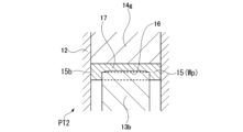
- a disk-shaped first material 11 is subjected to a rearward extrusion process to obtain a second material 15 as shown in FIG. 2(c), specifically, a bottomed cylindrical second material 15 having a recess 16 on the radially inner portion that opens to one axial side (upper side in FIG. 2(c)) and a bottom 17 on the other axial side of the recess 16 (lower side in FIG. 2(c)).
- the rearward extrusion process is performed using a die (punching tool, tool set) PT2 as shown in FIG. 2(c).
- the die shown in FIG. 2(c) includes a die 12 and die pin 13 similar to those in FIG. 2(b), and a cylindrical punch 14a with a smaller outer diameter than the punch 14 in FIG. 2(b).
- the punch 14a is coaxially positioned inside the upper part of the die 12.
- the punch 14a When performing rearward extrusion processing on the first material 11 using the die shown in FIG. 2(c), the punch 14a is retracted upward, and the first material 11 is fitted into the die 12 without any radial rattle, and placed on the upper surface of the die pin 13. In this state, the punch 14a is lowered to crush the radially inner portion of the first material 11 in the axial direction between the upper surface of the die pin 13 and the lower surface of the punch 14a.
- punch 14a (first member) moves relative to the workpiece (Wp) supported by the die pin 13.
- Punch 14a moves axially to approach the die pin 13.
- punch 14a With the relative axial movement between the workpiece Wp and punch 14a, punch 14a is pressed against the radially inner region of the workpiece Wp, and the tip portion of punch 14a is inserted into the workpiece Wp.
- a part of the material flows from the radially inner side of the workpiece Wp to the radially outer side.
- material flows in the opposite direction to the moving direction of punch 14a (backward flow).
- the thickness of the radially inner region decreases, while the thickness of the radially outer region increases.
- a recess (depression) 16 is formed in the radially inner region of the workpiece Wp, and a peripheral portion 15b surrounding the depression 16 is formed in the radially outer region. As the axial length of the peripheral portion 15b increases, the overall axial length of the workpiece Wp (the distance between the first axial end and the second axial end) increases.
- the recess 16 is a portion formed by pressing in the lower end of the punch 14a.
- the inner diameter of the recess 16 is smaller than the inner diameter of the cylindrical main body 22 (see FIG. 2(e)) constituting the ring-shaped member 20.
- the bottom 17 is a portion formed by axially crushing the radially inner portion of the first material 11. That is, the axial dimension of the bottom 17 is smaller than the axial dimension of the first material 11.
- the cylindrical radially outer portion of the second material 15 existing around the recess 16 and the bottom 17 is a portion whose axial dimension is expanded by causing the metal material of the radially inner portion of the first material 11 to flow radially outward.
- the axial dimension of the cylindrical radially outer portion is larger than the axial dimension of the first material 11.
- the second material 15 has an axial dimension smaller than the axial dimension of the outer ring 2 and an outer diameter the same as the outer diameter of the outer ring 2.
- a recess having an inner diameter equal to the inner diameter of the main body 22 of the ring-shaped member 20 is not formed in the workpiece by cold forging (backward extrusion), but rather a recess 16 having an inner diameter smaller than the inner diameter of the main body 22 is formed, thereby keeping the cross-sectional reduction rate of the workpiece small when forming the recess 16. This makes it possible to keep the forming load small when performing cold forging.
- the cross-sectional area reduction rate when obtaining the second material 15 from the first material 11 is preferably 80% or less, more preferably 60% or less, and even more preferably 45% or less.
- the bottom 17 of the second material 15 is punched out to obtain a third material 18 as shown in FIG. 2(d), specifically, a cylindrical third material 18 having an inner peripheral surface.
- the punching is performed using a die (punching tool, tool set) PT3 as shown in FIG. 2(d).
- the die shown in FIG. 2(d) comprises a die 12 similar to that in FIG. 2(b), a cylindrical punch 14b having the same outer diameter as the punch 14a in FIG. 2(c), and a sleeve 19.
- the sleeve 19 is cylindrical in shape and has an outer diameter slightly smaller than the inner diameter of the die 12 and an inner diameter the same as or slightly larger than the inner diameter of the recess 16 of the second material 15.
- the sleeve 19 is positioned inside the lower portion of the die 12 without any radial wobble.
- punch 14b (second member) moves relative to workpiece Wp supported by sleeve 19.
- Punch 14a moves axially to approach workpiece Wp, and the tip of punch 14a is pressed against bottom 17 of the recess in workpiece Wp. Furthermore, the tip of punch 14a moves to a position beyond workpiece Wp. That is, during the relative movement between workpiece Wp and punch 14b, with the axial surface of workpiece Wp supported by support surface 19y of sleeve 19, the tip of punch 14a and support surface 19y of sleeve 19 pass each other in the axial direction. Bottom 17 of the recess is punched out using punch 14a, and a peripheral wall Cw surrounding opening 18z is formed.
- the inner circumferential surface of the third material 18 is subjected to ironing to form an inner circumferential surface having an inner diameter larger than the inner diameter of the third material 18 and a cylindrical main body portion 22 having an axial dimension larger than the axial dimension of the third material 18, thereby obtaining a ring-shaped member 20 as shown in Figure 2(e).
- the ironing process is performed using a die (punching tool, tool set) PT4 as shown in Figure 2(e).
- the die shown in FIG. 2(e) includes a die 12 similar to that shown in FIG. 2(b), a cylindrical sleeve 19a, and a columnar punch 14c.
- the sleeve 19a has an outer diameter slightly smaller than the inner diameter of the die 12 and an inner diameter larger than the inner diameter of the third material 18, and is positioned inside the lower part of the die 12 without any radial wobble.
- the punch 14c has an ironing surface 21 on the outer peripheral surface of its lower end.
- the ironing surface 21 has a generally conical cylindrical shape with an outer diameter that decreases toward the bottom.
- the outer diameter of the lower end which is the minimum diameter portion of the ironing surface 21, is smaller than the inner diameter of the third material 18.
- the punch 14c is retracted upward and the third material 18 is fitted into the die 12 without any radial rattle, thereby constraining the outer peripheral surface of the third material 18 and preventing the outer peripheral surface from expanding in diameter, and the upper surface of the sleeve 19a supports the lower surface of the third material 18.
- the punch 14c is lowered and the ironing surface 21 is pressed from above downward into the inside of the third material 18, and then passed axially around the inside, thereby performing the ironing process on the inner peripheral surface of the third material 18.
- a large frictional force acts between the punch 14c and the main body 22, so when the punch 14c is returned upward, the punch 14c is returned upward against the main body 22 and the pressing sleeve while the upper surface of the main body 22 is pressed down by a pressing sleeve (not shown). This separates the punch 14c from the main body 22.
- the inner peripheral surface 12x of the die unit suppresses the expansion of the outer diameter of the peripheral wall Cw.
- the die unit has an inner peripheral surface 12x facing the outer peripheral surface of the workpiece Wp and a support surface 19z supporting the axial surface of the workpiece Wp.
- the inner diameter of the inner peripheral surface 12x of the die unit is set to be substantially equal or approximately the same as the outer diameter of the peripheral wall Cw before processing.
- the radial gap between the processing portion 40x of the punch 14c (third member) and the inner peripheral surface 12x of the die unit is set to be smaller than the thickness of the peripheral wall Cw before processing.
- the punch 14c In the relative movement between the workpiece Wp and the punch 14c, the punch 14c approaches the first axial end of the workpiece Wp from a state (40-i) separated from the workpiece Wp, and the punch 14c is inserted into the workpiece Wp in the axial direction from the first axial end side to the second axial end side of the workpiece Wp.
- the processed portion 40x pressed against the inner circumferential surface of the peripheral wall Cw moves from one axial side to the other axial side. The material of the workpiece Wp flows, and the workpiece Wp is deformed.
- the axial end of the punch 14c and the support surface 19z of the sleeve 19a approach each other relatively in the axial direction and reach substantially the same position (40-ii). Furthermore, in the relative movement between the workpiece Wp and the punch 14c, the tip of the punch 14c and the support surface 19z of the sleeve 19a pass each other in the axial direction (40-iii).
- the processed portion 40x of the punch 14c is pressed against the inner circumferential surface of the peripheral wall Cw throughout the entire axial direction of the workpiece Wp.
- the inner diameter of the peripheral wall Cw expands based on the flow of the material.
- the inner diameter of the peripheral wall Cw increases while the outer diameter is maintained throughout the entire axial and circumferential directions.
- the overall thickness of the peripheral wall Cw decreases, and the axial length of the peripheral wall Cw increases.
- the inner diameter of the workpiece used to manufacture the outer ring 2 is enlarged by cold forging (ironing), thereby keeping the cross-sectional area reduction rate of the workpiece low. This makes it possible to keep the forming load low when performing cold forging.
- the flow of the metal material occurs not only in the pushing direction of the punch 14c, but also in the opposite direction to the pushing direction of the punch 14c, which helps to enlarge the axial dimension of the workpiece. This makes it easier to improve the yield of the metal material.
- the process of enlarging the inner diameter of the workpiece by cold forging (ironing) is carried out while preventing the outer circumferential surface of the workpiece from expanding in diameter.
- the outer circumferential surface of the workpiece does not expand in diameter as a result of this process, and large circumferential tensile stress is not applied to the workpiece.
- damage such as cracks is less likely to occur in the workpiece.
- burr 23 is connected to the inner peripheral edge of the lower end of the main body 22, which is the forward side in terms of the direction of the ironing process, and has a cylindrical shape that extends in the axial direction. Therefore, in this example, an additional process is provided, as described below, of removing the burr 23.
- the inner diameter of the sleeve 19a is made the same as the outer diameter of the upper end, which is the maximum diameter part of the ironing surface 21, there is a possibility that burrs 23 will not be formed during the ironing process. If burrs 23 are not formed, processing to remove burrs 23 will not be necessary in the subsequent steps.
- the ring-shaped member 20a is obtained by compressing the main body 22 of the ring-shaped member 20 in the axial direction, specifically by compressing the axial dimension of the main body 22 to the same size as the axial dimension of the outer ring 2.
- this compression is performed using a die (punching tool, tool set) PT5 as shown in Figure 2(f).
- the die shown in FIG. 2(f) includes a die 12a, a cylindrical sleeve 19b, and a cylindrical punch 14d.
- the die 12a has a stepped cylindrical inner circumferential surface. That is, the inner circumferential surface of the die 12a is formed by connecting a lower small diameter cylindrical surface portion 24 and an upper large diameter cylindrical surface portion 25, which are arranged coaxially with each other, with a chamfered surface 26, which is a stepped surface.
- the small diameter cylindrical surface portion 24 has an inner diameter smaller than the outer diameter of the main body portion 22 of the ring-shaped member 20.
- the large diameter cylindrical surface portion 25 has an inner diameter the same as the inner diameter of the die 12 in FIG. 2(b) to FIG.
- the chamfered surface 26 has a cross-sectional shape of a concave arc that is curved and inclined in an upward direction as it moves radially outward.
- the sleeve 19b has an outer diameter slightly smaller than the inner diameter of the small diameter cylindrical surface portion 24, and an inner diameter the same as or slightly larger than the outer diameter of the burr 23 of the ring-shaped member 20.
- the sleeve 19b is positioned without any radial rattle inside the small diameter cylindrical surface portion 24.
- the punch 14d has an outer diameter slightly smaller than the inner diameter of the large diameter cylindrical surface portion 25, and is positioned without any radial rattle inside the large diameter cylindrical surface portion 25.
- the punch 14d is lowered, and the main body 22 is compressed in the axial direction between the chamfered surface 26 and the upper surface of the sleeve 19b and the lower surface of the punch 14d.
- the main body 22 is made into a cylindrical main body 22a having an axial dimension equal to the axial dimension of the outer ring 2, thereby obtaining a ring-shaped member 20a having the main body 22a and the burr 23.
- the main body 22a has an outer diameter equal to the outer diameter of the outer ring 2.
- the inner circumferential surface of the main body 22a has a convex arc-shaped cross section with the axial center portion projecting most radially inward, and at least the axial middle portion is located radially inward from the inner circumferential surface of the burr 23.
- the main body 22 in the process of forming the main body 22a described above, the main body 22 is compressed in the axial direction to form the main body 22a, and at the same time, the connection between the axial side surface of the main body 22 closest to the burr 23, which is the underside of the main body 22, and the outer circumferential surface is pressed strongly against the chamfered surface 26 to form a chamfered portion 8 at the connection.
- ring-shaped member 20a is processed to obtain ring-shaped member 20b.
- this processing is performed using a die (punching tool, tool set) PT6 as shown in FIG. 2(g).
- the inner diameter of the lower end portion which is the maximum diameter portion of the burr-removing surface 27, is the same as the outer diameter of the burr 23 of the ring-shaped member 20a or slightly larger than the inner diameter.
- the burr-removing surface 27 has an axial dimension larger than the burr 23.
- the punch 14e is positioned inside the large diameter cylindrical surface portion 25 without any radial wobble.
- the punch 14e is withdrawn upward, and the ring-shaped member 20a is turned upside down from the state shown in Fig. 2(f) with the burr 23 facing upward.
- the main body 22a of the ring-shaped member 20a is fitted into the large diameter cylindrical surface portion 25 of the die 12a without any radial wobble, thereby restraining the outer circumferential surface of the main body 22a and preventing the outer circumferential surface from expanding in diameter, and the lower surface of the main body 22a is supported by the chamfered processing surface 26 and the upper surface of the die pin 13a.
- the punch 14e is lowered and the burr-defeating surface 27 is pressed against the cylindrical burr 23 from above, thereby knocking the burr 23 radially inward.
- the burr 23 is deformed into a conical cylindrical shape along the burr-defeating surface 27 to form the burr 23a.
- the cylindrical burr 23 is deformed into a conical burr 23a to make it easier to remove the burr by shaving in the axial direction, which will be described later.
- the outside diameter of the base end of the burr 23a (the lower end in FIG. 2(g)) is the same as the outside diameter of the burr 23.
- a cylindrical main body 22b is formed having chamfered portions 8 at the connection portions between the outer circumferential surface and the side surfaces on both axial sides.
- ring-shaped member 20b is processed to obtain ring-shaped member 20c.
- this processing is performed using a die (punching tool, tool set) PT6 as shown in FIG. 2(h).
- the die shown in FIG. 2(h) comprises a die 12 similar to that in FIG. 2(b), a cylindrical sleeve 19c, and a columnar punch 14f.
- the sleeve 19c has an outer diameter slightly smaller than the inner diameter of the die 12, and an inner diameter the same as or slightly larger than the inner diameter of the outer ring 2.
- the sleeve 19c is positioned inside the lower part of the die 12 without any radial wobble.
- the punch 14f has an outer diameter the same as the inner diameter of the outer ring 2, and is positioned coaxially inside the die 12.
- the punch 14f When processing the ring-shaped member 20b using the die shown in FIG. 2(h), the punch 14f is withdrawn upward, and the body 22b of the ring-shaped member 20b is fitted into the die 12 without any radial wobble with the burr 23a of the ring-shaped member 20b facing up or down, and the lower surface of the body 22b is supported by the upper surface of the sleeve 19c. In this state, the punch 14f is lowered, and the inner peripheral portion of the body 22b and the burr 23a are shaved and removed in the axial direction by the punch 14f. This results in a cylindrical ring-shaped member 20c.
- the ring-shaped member 20c has an axial dimension the same as the axial dimension of the outer ring 2, an outer diameter the same as the outer diameter of the outer ring 2, and an inner diameter the same as the inner diameter of the outer ring 2.
- the ring-shaped member 20c is then subjected to a finishing process, such as cutting and grinding, to obtain the outer ring 2 having the finished shape.
- the forming load during cold forging in the main process can be kept small, so the press machine used to perform the forging can be made compact.
- the yield of the metal material that constitutes the outer ring 2 can be improved, so material costs can be reduced.
- damage such as cracks is less likely to occur in the workpiece, so the rate of defective products can be reduced.
- a finishing process of performing cutting, grinding, etc. on any of the ring-shaped members 20 in FIG. 2(e), 20a in FIG. 20(f), and 20b in FIG. 2(g) can be applied to obtain a ring-shaped member as a final product including an outer ring 2 having a finished shape.
- the processing for obtaining a bottomed cylindrical second material 15 from a disk-shaped first material 11 (see FIG. 2(b)) in this process for manufacturing the outer ring 2 (see FIG. 1) differs from that in the first example.
- forward extrusion processing is used as the processing.
- the forward extrusion processing is performed using a die (punching tool, tool set) as shown in FIG. 3.
- the mold shown in FIG. 3 includes a die 12 similar to that shown in FIG. 2(b), a cylindrical die pin 13b, and a cylindrical punch 14g.
- the die pin 13b has an outer diameter smaller than the inner diameter of the die 12, and is coaxially positioned inside the lower part of the die 12.
- the punch 14g has an outer diameter slightly smaller than the inner diameter of the die 12, and is positioned inside the upper part of the die 12 without any radial wobble.
- the punch 14g When performing forward extrusion processing on the first material 11 using the die shown in FIG. 3, the punch 14g is retracted upward, and the first material 11 is fitted into the die 12 without any radial rattle, and placed on the upper surface of the die pin 13b. In this state, the punch 14g is lowered to crush the radially inner portion of the first material 11 in the axial direction between the upper surface of the die pin 13b and the lower surface of the punch 14g. This causes the metal material of the radially inner portion to flow radially outward, thereby expanding the axial dimension of the radially outer portion, and forming a recess 16 that opens downward in the radially inner portion, thereby obtaining a bottomed cylindrical second material 15 having the recess 16 and a bottom 17.
- the workpiece Wp supported by the punch 14g moves relative to the die pin 13b (first member).
- the punch 14g and the workpiece Wp move axially to approach the die pin 13b.
- the die pin 13b With the relative axial movement between the workpiece Wp and the die pin 13b, the die pin 13b is pressed against the radial inner region of the workpiece Wp, and the tip portion of the die pin 13b is inserted into the workpiece Wp.
- a part of the material flows from the radial inner side of the workpiece Wp to the radial outer side.
- the material flows in the same direction as the movement direction of the punch 14g (forward flow).
- the thickness of the radial inner region decreases, while the thickness of the radial outer region increases.
- a recess (depression) 16 is formed in the radial inner region of the workpiece Wp, and a peripheral portion 15b surrounding the depression 16 is formed in the radial outer region. As the axial length of the peripheral portion 15b increases, the overall axial length of the workpiece Wp (the distance between the first axial end and the second axial end) increases.
- the method for obtaining a bottomed cylindrical second material 15 from a disk-shaped first material 11 is not limited to the backward extrusion process of the first embodiment, but may also employ the forward extrusion process of this embodiment.
- the other configurations and effects of this embodiment are the same as those of the first embodiment.
- the additional process for manufacturing the outer ring 2 (see FIG. 1) is different from the first example.
- the process shown in FIG. 3 can also be used instead of the process shown in FIG. 2(c).
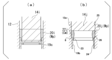
- the main body 22 of the ring-shaped member 20 (see FIG. 2(e)) is compressed in the axial direction to obtain the ring-shaped member 20d.
- the compression is performed using a die (punching tool, tool set) as shown in FIG. 4(a).
- the mold shown in FIG. 4(a) includes a die 12 and sleeve 19a similar to those in FIG. 2(e), and a punch 14d similar to those in FIG. 2(f).
- the punch 14d is withdrawn upward, and the main body 22 of the ring-shaped member 20 is fitted into the die 12 without any radial wobble with the burrs 23 of the ring-shaped member 20 facing downward, thereby constraining the outer peripheral surface of the main body 22 and preventing the outer peripheral surface from expanding in diameter, and the lower surface of the main body 22 is supported by the upper surface of the sleeve 19a.
- the punch 14d is lowered to compress the main body 22 in the axial direction between the upper surface of the sleeve 19a and the lower surface of the punch 14d.
- the main body 22 becomes a cylindrical main body 22c having an axial dimension equal to the axial dimension of the outer ring 2, thereby obtaining a ring-shaped member 20d having the main body 22c and the burrs 23.
- chamfered portion 8 (see FIG. 1) is not formed at the connection between the axial side surface, which is the lower surface of main body portion 22c, closest to burr 23, and the outer circumferential surface. This is different from the process of FIG. 2(f) in the first embodiment.
- ring-shaped member 20d is processed to obtain ring-shaped member 20e.
- the compression is performed using a die (punching tool, tool set) as shown in FIG. 4(b).
- the die shown in Fig. 4(b) includes a die 12 similar to that shown in Fig. 2(b), a punch 14e similar to that shown in Fig. 2(g), and a cylindrical die pin 13c.
- the die pin 13c has an outer diameter slightly smaller than the inner diameter of the die 12, and is positioned inside the lower part of the die 12 without any radial wobble.
- the punch 14e When processing the ring-shaped member 20d using the die shown in FIG. 4(b), the punch 14e is withdrawn upward, and the body portion 22c of the ring-shaped member 20d is fitted into the die 12 without any radial wobble with the burr 23 of the ring-shaped member 20d facing upward, thereby constraining the outer circumferential surface of the body portion 22c and preventing the outer circumferential surface from expanding, and the lower surface of the body portion 22c is supported by the upper surface of the die pin 13c.
- the chamfered portion 8 (see FIG. 1) is not formed at the connection between the axial side surface, which is the underside of the main body portion 22d, away from the burr 23, and the outer circumferential surface. This is different from the process of FIG. 2(g) in the first embodiment.
- ring-shaped member 20e is processed to obtain ring-shaped member 20f.
- the sleeve 19c and punch 14f are used to shave and remove the inner peripheral portion and burrs 23a of the main body 22d of the ring-shaped member 20e in the axial direction to obtain the cylindrical ring-shaped member 20f.
- the ring-shaped member 20f is then subjected to a finishing process in which cutting, grinding, and other processes are performed to obtain the outer ring 2 having a finished shape.
- the chamfered portion 8 of the outer ring 2 is formed in this finishing process.
- the chamfered portions 8 of the outer ring 2 are not formed in the additional process, so the shape of the inner peripheral surface of the die (punching tool, tool set) used in the additional process, specifically the die 12 in Figures 4(a) and 4(b), can be simplified.
- the other configurations and effects of this example are the same as those of the first embodiment.
- the outer ring 2 having a finished shape can be obtained by the finishing process in which cutting, grinding, or the like is performed on either the ring-shaped member 20d in FIG. 4(a) or the ring-shaped member 20e in FIG. 4(b).
- the additional process for manufacturing the outer ring 2 (see FIG. 1) is different from the first example.
- the process shown in FIG. 3 can also be used instead of the process shown in FIG. 2(c).
- ring-shaped member 20 (see FIG. 2(e)) is processed to obtain ring-shaped member 20g.
- this processing is performed using a die (punching tool, tool set) as shown in FIG. 5.
- the mold shown in FIG. 5 has a die 12, sleeve 19c, and punch 14f similar to those in FIG. 2(h).
- a finishing process is then applied to the ring-shaped member 20g, which involves machining, grinding, and the like, to obtain the outer ring 2 having a finished shape.
- the finishing of the axial dimension of the outer ring 2 and the formation of each chamfered portion 8 of the outer ring 2 are performed in this finishing process.
- the additional process does not include finishing the axial dimension of the outer ring 2, forming the chamfered portions 8 of the outer ring 2, or bending the cylindrical burrs 23 radially inward, so the number of steps in the additional process can be reduced.
- the other configurations and effects of this example are the same as those of the first embodiment.
- the additional process for manufacturing the outer ring 2 is different from that of the first example.
- the additional process of this example is the same as that of the first example up to Figure 2(f).
- the process shown in Figure 3 can also be used instead of the process shown in Figure 2(c).
- the ring-shaped member 20a obtained in the step shown in FIG. 2(f) is processed to obtain the ring-shaped member 20h.
- the processing is performed using a die (punching tool, tool set) as shown in FIG. 6.
- the mold shown in FIG. 6 includes a die 12a and die pin 13a similar to those in FIG. 2(g), and a punch 14h.
- the punch 14h is cylindrically configured and has an outer diameter slightly smaller than the inner diameter of the large diameter cylindrical surface portion 25 of the die 12a, and an inner diameter the same as or slightly larger than the outer diameter of the burr 23.
- the punch 14h is positioned inside the large diameter cylindrical surface portion 25 without any radial rattling.
- the punch 14h When processing the ring-shaped member 20a using the die shown in FIG. 6, the punch 14h is retracted upward, and the main body 22a of the ring-shaped member 20a is fitted into the large-diameter cylindrical surface 25 of the die 12a without any radial wobble, with the burr 23 of the ring-shaped member 20a facing upward. This restrains the outer circumferential surface of the main body 22a, preventing the outer circumferential surface from expanding, and supports the lower surface of the main body 22a by the chamfered surface 26 and the upper surface of the die pin 13a.
- the punch 14h is lowered and the lower surface of the punch 14h presses the upper surface of the main body 22a, so that the connection between the axial side surface farther from the burr 23, which is the lower surface of the main body 22a, and the outer circumferential surface is strongly pressed against the chamfered surface 26, forming a chamfered portion 8 at the connection.
- a main body 22b having a chamfered portion 8 at each connection between the side surfaces on both axial sides and the outer circumferential surface is formed.
- the cylindrical burr 23 is not machined at this time. This is different from the process in FIG. 2(g) of the first example.
- a finishing process is then applied to the ring-shaped member 20h, which involves machining, grinding, and the like, to obtain the outer ring 2 having a finished shape.
- the inner diameter of the outer ring 2 is finished and burrs 23 are removed in this finishing process.
- the number of steps in the additional process can be reduced because the finishing of the inner diameter of the outer ring 2 and the removal of burrs 23 are not performed in the additional process.
- the other configurations and effects of this example are the same as those of the first embodiment.
- This example is an example of manufacturing a ring-shaped member to obtain the inner ring 3 of the rolling bearing 1 shown in Figure 1 using one embodiment of the method for manufacturing a ring-shaped member.
- the manufacturing method of the inner ring 3 in this example includes a main process and additional processing to obtain a ring-shaped member by one embodiment of the manufacturing method, and a finishing process to obtain the final shape of the inner ring 3 by a finishing process thereafter. Note that all of the processing in these processes is cold processing.
- the main process is the same as the main process shown in Figures 2(a) to 2(e) of the first embodiment. That is, in this example, a cylindrical billet 10A as shown in Figure 7(a) is subjected to upsetting processing to crush it in the axial direction to obtain a disk-shaped first material 11A as shown in Figure 7(b), and the first material 11A is subjected to rearward extrusion processing to obtain a bottomed cylindrical second material 15A having a recess 16A and a bottom 17A as shown in Figure 7(c), and the bottom 17A of the second material 15A is punched out to obtain a cylindrical third material 18A as shown in Figure 7(d).
- the processing for obtaining the second material 15A can also be performed by forward extrusion processing instead of rearward extrusion processing.
- the inner circumferential surface of the third material 18A is subjected to ironing to form an inner circumferential surface having an inner diameter larger than the inner diameter of the third material 18A and a cylindrical main body portion 22A having an axial dimension larger than the axial dimension of the third material 18A, thereby obtaining a ring-shaped member 20A as shown in Figure 7 (e).
- the ring-shaped member 20A also further includes a cylindrical burr 23A connected to the inner circumferential edge portion of the lower end of the main body portion 22A.
- the inner peripheral portion and burrs 23A of the main body 22A of the ring-shaped member 20A are shaved in the axial direction and removed by a process similar to that of the fourth embodiment shown in FIG. 5, to obtain a ring-shaped member 20B consisting only of a cylindrical main body 22B as shown in FIG. 7(f).
- the ring-shaped member 20B is further processed to obtain a ring-shaped member 20C consisting only of a cylindrical main body 22C as shown in FIG. 7(g). In this example, this processing is performed using a mold (punching tool, tool set) as shown in FIG. 7(g).
- the mold shown in FIG. 7(g) includes a die 12A, a die pin 13A, and a punch 14A.
- the die 12A has a cylindrical inner surface on which the die pin 13A and punch 14A are arranged.
- the inner diameter of the die 12A is the same as the outer diameter of the ring-shaped member 20B.
- the die pin 13A is configured as a stepped cylinder, and includes a cylindrical main body 28A with an outer diameter slightly smaller than the inner diameter of the die 12A, and a cylindrical small diameter portion 29A with a smaller diameter than the main body 28A, protruding upward from the center of the upper surface of the main body 28A.
- the outer diameter of the small diameter portion 29A is the same as the inner diameter of the ring-shaped member 20B.
- the die pin 13A is provided with a chamfered surface 30A at the connection between the outer circumferential surface of the small diameter portion 29A and the upper surface of the main body 28A, which has a cross-sectional shape of a concave arc that is curved and inclined in a direction in which the outer diameter increases toward the bottom.
- the main body 28A of the die pin 13A is fitted inside the lower part of the die 12A without any radial rattle.
- the punch 14A is configured as a stepped cylinder, and includes a cylindrical body 28B with an outer diameter slightly smaller than the inner diameter of the die 12A, and a cylindrical small diameter portion 29B with a smaller diameter than the body 28B that protrudes downward from the center of the lower surface of the body 28B.
- the outer diameter of the small diameter portion 29B is the same as the inner diameter of the ring-shaped member 20B.
- the punch 14A includes a chamfered surface 30B having a concave arc-shaped cross-sectional shape that is curved in a direction in which the outer diameter increases toward the upper side.
- the body 28B of the punch 14A is fitted inside the upper part of the die 12A without any radial rattle.
- punch 14A is retracted upward and ring-shaped member 20B is fitted into die 12A without any radial rattle, thereby constraining the outer circumferential surface of ring-shaped member 20B and preventing the outer circumferential surface from expanding in diameter, and inserting small diameter portion 29A of die pin 13A into the inside of the lower part of ring-shaped member 20B without any radial rattle. Furthermore, punch 14A is lowered and inserting small diameter portion 29B of punch 14A into the inside of the upper part of ring-shaped member 20B without any radial rattle.
- the punch 14A is further lowered to strongly press the connection portion between the lower axial side surface and the inner peripheral surface of the ring-shaped member 20B against the chamfered surface 30A of the die pin 13A, and strongly press the connection portion between the upper axial side surface and the inner peripheral surface of the ring-shaped member 20B against the chamfered surface 30B of the punch 14A.
- a chamfered portion 9 is formed at each connection portion.
- the ring-shaped member 20B is compressed in the axial direction between the upper surface of the main body portion 28A of the die pin 13A and the lower surface of the main body portion 28B of the punch 14A.
- the axial dimension of the ring-shaped member 20B is reduced to the same size as the axial dimension of the inner ring 3.
- a part of the metal material that flows with the reduction enters between the upper surface of the small diameter portion 29A of the die pin 13A and the lower surface of the small diameter portion 29B of the punch 14A, forming an excess part 31 that protrudes radially inward at the axial middle part of the main body portion 22C. That is, in this example, the ring-shaped member 20C is obtained by the processing described above.
- the ring-shaped member 20C is processed to obtain a cylindrical ring-shaped member 20D as shown in FIG. 7(h).
- the processing is performed using a die (punching tool, tool set) as shown in FIG. 7(h).
- the die shown in FIG. 7(h) includes a die 12A similar to that shown in FIG. 7(g), a cylindrical sleeve 19A, and a punch 14B.
- the sleeve 19A has an outer diameter slightly smaller than the inner diameter of the die 12A, and an inner diameter the same as that of the inner ring 3.
- the sleeve 19A is positioned inside the lower part of the die 12A without any radial play.
- the punch 14B has an outer diameter the same as that of the inner ring 3, and is positioned coaxially inside the die 12.
- the punch 14B When processing the ring-shaped member 20C using the die shown in FIG. 7(h), the punch 14B is retracted upward, and the ring-shaped member 20C is fitted into the die 12 without any radial wobble, and the lower surface of the ring-shaped member 20C is supported by the upper surface of the sleeve 19A. In this state, the punch 14B is lowered and the excess material 31 is shaved and removed in the axial direction by the punch 14B to obtain the cylindrical ring-shaped member 20D.
- the ring-shaped member 20D has an axial dimension the same as the axial dimension of the inner ring 3, an outer diameter the same as the outer diameter of the inner ring 3, and an inner diameter the same as the inner diameter of the inner ring 3.
- the ring-shaped member 20D is then subjected to a finishing process, such as cutting and grinding, to obtain the inner ring 3 having a finished shape.
- a finishing process such as cutting and grinding
- At least some of the work of finishing the axial dimension, forming the chamfered portion, and removing burrs can also be performed in the finishing process for the inner ring 3.
- an inner ring 3 having a finished shape can be obtained by applying a finishing process to any of the ring-shaped members 20A in FIG. 7(e), 20B in FIG. 7(f), and 20C in FIG. 7(g) through cutting, grinding, and the like.
- the timing of the shaving process is different from that in the first embodiment.
- shaving is performed using a punch 14i as shown in FIG. 8(a).
- This shaving process is similar to the step in FIG. 2(h).
- the body portion 22j of the ring-shaped member 20j is compressed in the axial direction using a punch 14j as shown in FIG. 8(b).
- This compression process is similar to the step in FIG. 2(f).
- this example does not include a step of removing burrs, and a ring-shaped member 20j with burrs 23 is obtained. If necessary, the burrs 23 can be removed in a later step.
- the timing of the shaving process is different from that in the first example, but similar to that in the seventh example.
- the forward extrusion process shown in FIG. 3 is used as the process for obtaining a bottomed cylindrical second material 15 from a disk-shaped first material 11 (see FIG. 2(b)).
- a punch 14k is used to compress the main body 22k of the ring-shaped member 20k in the axial direction. This compression process is similar to the process in FIG. 6.
- no burr removal process is provided, and a ring-shaped member 20k with burrs 23 is obtained. If necessary, the burrs 23 can be removed in a subsequent process.
- a punching tool PT1 is used to form a workpiece Wp having a different shape from the example of FIG. 2(b).
- the workpiece Wp after processing in the first process has a generally cylindrical shape (generally disk shape) including a first axial surface, a second axial surface, and an outer peripheral surface, and further has a first portion 81 and a second portion 82 having different thicknesses in the radially outer region.
- the thickness (axial length) of the second portion 82 is larger than the thickness (axial length) of the first portion 81.
- the second portion 82 is located radially outward compared to the first portion 81.
- the workpiece Wp includes a second portion 82 including a convex portion 80 protruding in the axial direction in the radially outer region.
- a groove 85 is provided on one surface of the die unit.
- the punching tool PT1 is designed based on the shape parameters of the final ring-shaped member and the processing parameters of other processes, and the initial shape of the workpiece Wp is set. This shape control at the initial stage improves the efficiency of material use (material yield).
- the quality of the product for example, improving the strength of the product
- punch 14n (first member) moves relative to workpiece Wp supported on the support surface of die unit 12n.
- Punch 14n moves axially to approach the support surface of die unit 12n.
- punch 14n is pressed against the radial inner region of workpiece Wp, and the tip portion of punch 14n is inserted into workpiece Wp.
- a part of the material flows from the radial inner side to the radial outer side of workpiece Wp.
- material flows in the opposite direction to the moving direction of punch 14n (backward flow).
- a recess (recess) 16B is formed in the radial inner region of workpiece Wp, and a peripheral portion 15B surrounding recess 16B is formed in the radial outer region. As the axial length of the peripheral portion 15B increases, the overall axial length of the workpiece Wp (the distance between the first axial end and the second axial end) increases.
- the punch 14p has a tip portion 71, an intermediate portion 72, and a shaping portion 73 located between the tip portion 71 and the intermediate portion 72 in the axial direction.
- the tip portion 71 has a first outer diameter.
- the first outer diameter is set to be approximately the same size as the bottom portion 17 of the workpiece Wp before punching.
- the intermediate portion 72 has a second outer diameter.
- the second outer diameter is set to be larger than the size of the bottom portion 17.
- the shaping portion 73 has an inclined surface inclined with respect to the central axis of the punch 14p.
- the inclined surface of the shaping portion 73 gradually expands in diameter from the tip portion 71 side toward the intermediate portion 72 side.
- the shaping portion 73 can have a shape different from the above.
- the shaping portion 73 can have a stepped shape and/or a curved shape.
- the bottom 17B of the recess is punched out using the punch 14p, forming a ring-shaped member 18B (workpiece Wp).
- the workpiece Wp has a main body 18p (peripheral wall Cw) surrounding an opening 18z.
- the shaping portion 73 of the punch 14p is pressed against the workpiece Wp, changing the shape of the workpiece Wp.
- the material of the workpiece Wp flows in response to contact with the shaping portion 73.
- an inclined surface 18y is formed at the corner between the first axial surface AX1 and the inner peripheral surface of the peripheral wall Cw.
- the processing portion 40y of the punch 14s is pressed against the inner surface of the peripheral wall Cw while suppressing the expansion of the outer diameter of the peripheral wall Cw, and the inner diameter of the peripheral wall Cw expands.
- the inner diameter of the peripheral wall Cw expands while the outer diameter is maintained throughout the entire axial and circumferential directions.
- the overall thickness of the peripheral wall Cw decreases, and the axial length of the peripheral wall Cw expands.
- the orientation of the workpiece Wp set in the die unit is reversed. That is, in the process shown in FIG. 10(c), the second axial surface AX2 of the workpiece Wp is supported by the die unit, and punch 14 is inserted into the workpiece Wp from the side of the first axial surface AX1. On the other hand, in the process shown in FIG. 10(d), the first axial surface AX1 is supported by the die unit, and punch (third member) 14s is inserted into the workpiece from the side of the second axial surface AX2.
- the workpiece (Wp) before processing is thin and has a small volume in the portion close to the first axial surface. Also, the portion close to the second axial surface is thick and has a large volume.
- the punch (third member) 14s is inserted into the workpiece Wp from the side of the first axial surface AX1, which has a large volume.
- a flow occurs in which the material moves from the side of the second axial surface AX2 to the side of the first axial surface AX1.
- a part of the material flows from the part with a large volume to the part with a small volume.
- the volume (thickness) of the material is made uniform throughout the entire axial direction of the peripheral wall.
- a ring-shaped member 20s that is substantially free of burrs is obtained, as shown in FIG. 10(e).
- the generation of burrs is suppressed, and the efficiency of material use (material yield) is improved.
- the quality of the product is improved.
Landscapes
- Engineering & Computer Science (AREA)
- Mechanical Engineering (AREA)
- General Engineering & Computer Science (AREA)
- Manufacturing & Machinery (AREA)
- Rolling Contact Bearings (AREA)
- Forging (AREA)
Priority Applications (5)
| Application Number | Priority Date | Filing Date | Title |
|---|---|---|---|
| JP2024514483A JP7552957B1 (ja) | 2022-12-21 | 2023-10-30 | リング状部材の製造方法、軸受の製造方法、機械部品の製造方法、車両の製造方法、機械装置の製造方法、リング状部材、軸受要素、軸受、機械装置、及び車両 |
| CN202380084091.9A CN120322300A (zh) | 2022-12-21 | 2023-10-30 | 环状部件的制造方法、轴承的制造方法、机械构件的制造方法、车辆的制造方法、机械装置的制造方法、环状部件、轴承要素、轴承、机械装置及车辆 |
| EP23906476.9A EP4491298A4 (en) | 2022-12-21 | 2023-10-30 | METHOD FOR MANUFACTURING ANNULAR-SHAPED ELEMENT, METHOD FOR MANUFACTURING A BEARING, METHOD FOR MANUFACTURING A MECHANICAL COMPONENT, METHOD FOR MANUFACTURING A VEHICLE, METHOD FOR MANUFACTURING A MECHANICAL DEVICE, ANNULAR-SHAPED ELEMENT, BEARING ELEMENT, BEARING, MECHANICAL DEVICE, AND VEHICLE |
| JP2024149378A JP2024167349A (ja) | 2022-12-21 | 2024-08-30 | リング状部材の製造方法、軸受の製造方法、機械部品の製造方法、車両の製造方法、機械装置の製造方法、リング状部材、軸受要素、軸受、機械装置、及び車両 |
| US19/204,864 US20250269421A1 (en) | 2022-12-21 | 2025-05-12 | Method for manufacturing ring-shaped member, method for manufacturing bearing, method for manufacturing machine part, method for manufacturing vehicle, method for manufacturing mechanical device, ring-shaped member, bearing element, bearing, mechanical device, and vehicle |
Applications Claiming Priority (2)
| Application Number | Priority Date | Filing Date | Title |
|---|---|---|---|
| JP2022-204298 | 2022-12-21 | ||
| JP2022204298 | 2022-12-21 |
Related Child Applications (1)
| Application Number | Title | Priority Date | Filing Date |
|---|---|---|---|
| US19/204,864 Continuation US20250269421A1 (en) | 2022-12-21 | 2025-05-12 | Method for manufacturing ring-shaped member, method for manufacturing bearing, method for manufacturing machine part, method for manufacturing vehicle, method for manufacturing mechanical device, ring-shaped member, bearing element, bearing, mechanical device, and vehicle |
Publications (1)
| Publication Number | Publication Date |
|---|---|
| WO2024135104A1 true WO2024135104A1 (ja) | 2024-06-27 |
Family
ID=91588352
Family Applications (1)
| Application Number | Title | Priority Date | Filing Date |
|---|---|---|---|
| PCT/JP2023/039111 Ceased WO2024135104A1 (ja) | 2022-12-21 | 2023-10-30 | リング状部材の製造方法、軸受の製造方法、機械部品の製造方法、車両の製造方法、機械装置の製造方法、リング状部材、軸受要素、軸受、機械装置、及び車両 |
Country Status (5)
| Country | Link |
|---|---|
| US (1) | US20250269421A1 (https=) |
| EP (1) | EP4491298A4 (https=) |
| JP (2) | JP7552957B1 (https=) |
| CN (1) | CN120322300A (https=) |
| WO (1) | WO2024135104A1 (https=) |
Citations (8)
| Publication number | Priority date | Publication date | Assignee | Title |
|---|---|---|---|---|
| JPH05277614A (ja) * | 1992-03-31 | 1993-10-26 | Ntn Corp | リング状品の鍛造装置 |
| JPH079064A (ja) * | 1993-06-25 | 1995-01-13 | Nippon Seiko Kk | 玉軸受用外輪の製造方法 |
| JP3422941B2 (ja) | 1998-09-17 | 2003-07-07 | 日本高周波鋼業株式会社 | リング状部品の製造方法 |
| JP2009297731A (ja) | 2008-06-11 | 2009-12-24 | Sanyo Special Steel Co Ltd | ベアリング外輪素形材の製造方法 |
| JP2012045577A (ja) * | 2010-08-26 | 2012-03-08 | Nsk Ltd | 円錐ころ軸受の外輪の製造方法 |
| JP2012101264A (ja) * | 2010-11-12 | 2012-05-31 | Okita Tekkosho:Kk | ダブルボールベアリング用内・外輪の鍛造方法 |
| JP2018530432A (ja) * | 2015-10-14 | 2018-10-18 | ハテブル ウムフオルマシネン アクチエンゲゼルシャフト | リング状成形品の製造方法および製造設備 |
| CN114406604A (zh) * | 2021-11-18 | 2022-04-29 | 中国航发哈尔滨轴承有限公司 | 一种控制金属流线沿沟道分布的偏心球轴承外圈的成形方法 |
Family Cites Families (3)
| Publication number | Priority date | Publication date | Assignee | Title |
|---|---|---|---|---|
| JP3221639B2 (ja) * | 1994-01-14 | 2001-10-22 | ヒーハイスト精工株式会社 | フランジ付リニアボールベアリングの成型方法 |
| JP2006090407A (ja) * | 2004-09-22 | 2006-04-06 | Nsk Ltd | ラジアル玉軸受用軌道輪及びその製造方法 |
| EP4407202A3 (en) * | 2020-07-07 | 2024-10-23 | NSK Ltd. | Method for manufacturing bearing element, method for manufacturing bearing, method for manufacturing machine, method for manufacturing vehicle |
-
2023
- 2023-10-30 JP JP2024514483A patent/JP7552957B1/ja active Active
- 2023-10-30 WO PCT/JP2023/039111 patent/WO2024135104A1/ja not_active Ceased
- 2023-10-30 EP EP23906476.9A patent/EP4491298A4/en active Pending
- 2023-10-30 CN CN202380084091.9A patent/CN120322300A/zh active Pending
-
2024
- 2024-08-30 JP JP2024149378A patent/JP2024167349A/ja active Pending
-
2025
- 2025-05-12 US US19/204,864 patent/US20250269421A1/en active Pending
Patent Citations (8)
| Publication number | Priority date | Publication date | Assignee | Title |
|---|---|---|---|---|
| JPH05277614A (ja) * | 1992-03-31 | 1993-10-26 | Ntn Corp | リング状品の鍛造装置 |
| JPH079064A (ja) * | 1993-06-25 | 1995-01-13 | Nippon Seiko Kk | 玉軸受用外輪の製造方法 |
| JP3422941B2 (ja) | 1998-09-17 | 2003-07-07 | 日本高周波鋼業株式会社 | リング状部品の製造方法 |
| JP2009297731A (ja) | 2008-06-11 | 2009-12-24 | Sanyo Special Steel Co Ltd | ベアリング外輪素形材の製造方法 |
| JP2012045577A (ja) * | 2010-08-26 | 2012-03-08 | Nsk Ltd | 円錐ころ軸受の外輪の製造方法 |
| JP2012101264A (ja) * | 2010-11-12 | 2012-05-31 | Okita Tekkosho:Kk | ダブルボールベアリング用内・外輪の鍛造方法 |
| JP2018530432A (ja) * | 2015-10-14 | 2018-10-18 | ハテブル ウムフオルマシネン アクチエンゲゼルシャフト | リング状成形品の製造方法および製造設備 |
| CN114406604A (zh) * | 2021-11-18 | 2022-04-29 | 中国航发哈尔滨轴承有限公司 | 一种控制金属流线沿沟道分布的偏心球轴承外圈的成形方法 |
Non-Patent Citations (1)
| Title |
|---|
| See also references of EP4491298A4 |
Also Published As
| Publication number | Publication date |
|---|---|
| JPWO2024135104A1 (https=) | 2024-06-27 |
| EP4491298A4 (en) | 2025-10-01 |
| JP2024167349A (ja) | 2024-12-03 |
| CN120322300A (zh) | 2025-07-15 |
| US20250269421A1 (en) | 2025-08-28 |
| EP4491298A1 (en) | 2025-01-15 |
| JP7552957B1 (ja) | 2024-09-18 |
Similar Documents
| Publication | Publication Date | Title |
|---|---|---|
| US8950283B2 (en) | Method for manufacturing nut for ball screw and ball screw | |
| US20250092914A1 (en) | Bearing element manufacturing method, bearing manufacturing method, machine manufacturing method, vehicle manufacturing method, bearing element, bearing, machine, and vehicle | |
| JP2009279627A (ja) | 転がり軸受の内外輪の製造方法 | |
| JP3192979B2 (ja) | 基部外面上に円筒部が一体形成されてなる金属成形品の成形装置並びにかかる金属成形品の成形方法 | |
| JP6641903B2 (ja) | リング状部材の製造方法 | |
| JP7552957B1 (ja) | リング状部材の製造方法、軸受の製造方法、機械部品の製造方法、車両の製造方法、機械装置の製造方法、リング状部材、軸受要素、軸受、機械装置、及び車両 | |
| JP6365796B1 (ja) | 軌道溝の加工方法、ボールねじ装置、機械及び車両の製造方法 | |
| JP2013049094A (ja) | 金属製部品の塑性加工装置 | |
| JP7140306B1 (ja) | 転がり軸受、車両、機械、プレス成形品の製造方法、転がり軸受の製造方法、車両の製造方法及び機械の製造方法 | |
| JP5082867B2 (ja) | 自在継手用ヨークの製造方法 | |
| JP5239933B2 (ja) | 金属製リング状部品の製造方法 | |
| JP4978552B2 (ja) | リング状軌道輪素材の製造方法 | |
| US20030171198A1 (en) | Method for producing a deep rolling roller, and deep rolling roller | |
| JP2025072220A (ja) | ボルトの製造方法 | |
| KR20250052064A (ko) | 자율주행 전기 자동차 전자조향 시스템의 sfa 너트 냉간단조 방법 및 장치 | |
| JPS6390332A (ja) | 等速自在継手外輪の加工方法およびその装置 | |
| JP6723103B2 (ja) | 軸の製造方法 | |
| JP2005262298A (ja) | 鍛造品の穴あけ方法およびその穴あけ装置 | |
| JP2025126002A (ja) | ボールねじ用ナットの製造方法、及びボールねじ | |
| Wear | R&D Update: Blanking and edge fracture in flanging of AHSS, Part II | |
| JPH10137881A (ja) | 動圧溝付き軸受の加工方法 | |
| JP2005296974A (ja) | かさ歯車の製造方法 | |
| JPH11210763A (ja) | 軸受内輪及びその製造方法、並びにクラッチレリーズ軸受 | |
| JP2002301538A (ja) | ハスバ歯車素材加工方法 | |
| JPS61147941A (ja) | 自在継手外輪の製造方法及びその製造装置 |
Legal Events
| Date | Code | Title | Description |
|---|---|---|---|
| WWE | Wipo information: entry into national phase |
Ref document number: 2024514483 Country of ref document: JP |
|
| 121 | Ep: the epo has been informed by wipo that ep was designated in this application |
Ref document number: 23906476 Country of ref document: EP Kind code of ref document: A1 |
|
| WWE | Wipo information: entry into national phase |
Ref document number: 2023906476 Country of ref document: EP |
|
| ENP | Entry into the national phase |
Ref document number: 2023906476 Country of ref document: EP Effective date: 20241010 |
|
| WWE | Wipo information: entry into national phase |
Ref document number: 202380084091.9 Country of ref document: CN |
|
| WWP | Wipo information: published in national office |
Ref document number: 202380084091.9 Country of ref document: CN |
|
| NENP | Non-entry into the national phase |
Ref country code: DE |