WO2024100804A1 - 型締装置 - Google Patents
型締装置 Download PDFInfo
- Publication number
- WO2024100804A1 WO2024100804A1 PCT/JP2022/041720 JP2022041720W WO2024100804A1 WO 2024100804 A1 WO2024100804 A1 WO 2024100804A1 JP 2022041720 W JP2022041720 W JP 2022041720W WO 2024100804 A1 WO2024100804 A1 WO 2024100804A1
- Authority
- WO
- WIPO (PCT)
- Prior art keywords
- shielding member
- fixed
- opening
- mold
- clamping device
- Prior art date
- Legal status (The legal status is an assumption and is not a legal conclusion. Google has not performed a legal analysis and makes no representation as to the accuracy of the status listed.)
- Ceased
Links
Images





Classifications
-
- B—PERFORMING OPERATIONS; TRANSPORTING
- B29—WORKING OF PLASTICS; WORKING OF SUBSTANCES IN A PLASTIC STATE IN GENERAL
- B29C—SHAPING OR JOINING OF PLASTICS; SHAPING OF MATERIAL IN A PLASTIC STATE, NOT OTHERWISE PROVIDED FOR; AFTER-TREATMENT OF THE SHAPED PRODUCTS, e.g. REPAIRING
- B29C33/00—Moulds or cores; Details thereof or accessories therefor
- B29C33/20—Opening, closing or clamping
-
- B—PERFORMING OPERATIONS; TRANSPORTING
- B29—WORKING OF PLASTICS; WORKING OF SUBSTANCES IN A PLASTIC STATE IN GENERAL
- B29C—SHAPING OR JOINING OF PLASTICS; SHAPING OF MATERIAL IN A PLASTIC STATE, NOT OTHERWISE PROVIDED FOR; AFTER-TREATMENT OF THE SHAPED PRODUCTS, e.g. REPAIRING
- B29C45/00—Injection moulding, i.e. forcing the required volume of moulding material through a nozzle into a closed mould; Apparatus therefor
- B29C45/17—Component parts, details or accessories; Auxiliary operations
- B29C45/64—Mould opening, closing or clamping devices
-
- B—PERFORMING OPERATIONS; TRANSPORTING
- B29—WORKING OF PLASTICS; WORKING OF SUBSTANCES IN A PLASTIC STATE IN GENERAL
- B29C—SHAPING OR JOINING OF PLASTICS; SHAPING OF MATERIAL IN A PLASTIC STATE, NOT OTHERWISE PROVIDED FOR; AFTER-TREATMENT OF THE SHAPED PRODUCTS, e.g. REPAIRING
- B29C45/00—Injection moulding, i.e. forcing the required volume of moulding material through a nozzle into a closed mould; Apparatus therefor
- B29C45/17—Component parts, details or accessories; Auxiliary operations
- B29C45/84—Safety devices
Definitions
- This disclosure relates to a mold clamping device.
- JP 04-355109 A discloses an injection molding machine that has a bellows-shaped cover member that covers the mold.
- the disclosed embodiment is a mold clamping device that opens and closes a mold mounted between a fixed platen and a movable platen, and includes a linear guide member that guides the movement of the movable platen, and a shielding member that is fixed to the movable platen, extends from the movable platen toward the fixed platen, and shields a portion of the linear guide member, and the entire shielding member moves in conjunction with the movement of the movable platen.
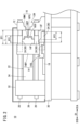
- FIG. 1 is an external view showing a mold clamping device in an open state.
- FIG. 2 is an external view showing the mold clamping device in a mold closed state.
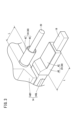
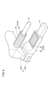
- FIG. 3 is a diagram showing the shielding member.
- FIG. 4 is a diagram showing a state in which a part of the linear guide member that is shielded by the shielding member is exposed.
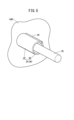
- FIG. 5 is a diagram showing a first shielding member of the first modified example.
- FIG. 6 is a diagram showing a state in which a part of the tie bar that is shielded by the first shielding member of the first modification is exposed.
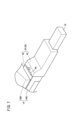
- FIG. 7 is a diagram showing a second shielding member according to the second modification.
- FIG. 1 is an external view showing a mold clamping device in an open state.
- FIG. 2 is an external view showing the mold clamping device in a mold closed state.
- FIG. 3 is a diagram showing the shielding member.
- FIG. 4 is a diagram showing a state in which a part of the
- FIG. 8 is a diagram showing a state in which a part of the guide rail that is shielded by the second shielding member of the second modification is exposed.
- FIG. 9 is a diagram showing a shielding member according to the third modification.
- FIG. 10 is a diagram showing a state in which a part of the linear motion guide member that is shielded by the shielding member of the third modification is exposed.
- FIG. 1 is an external view showing the clamping device 10 in the mold open state.
- FIG. 2 is an external view showing the clamping device 10 in the mold closed state.
- the clamping device 10 is a device that opens and closes the mold 16 mounted between a fixed platen 12 and a movable platen 14.
- the clamping device 10 has the fixed platen 12, the movable platen 14, the mold 16, a guide rail 18, tie bars 20, a clamping drive unit 22, a shielding member 24, and a protective cover 26.
- the fixed platen 12 is mounted on a stand 30.
- An injection device (not shown) is placed on the stand 30.
- the fixed platen 12 is located between the injection device and the movable platen 14.
- a through hole 12H is formed in the fixed platen 12. The through hole 12H penetrates the fixed platen 12 from the mold placement surface 12F of the fixed platen 12 to the surface opposite the mold placement surface 12F.
- the movable platen 14 is disposed between the fixed platen 12 and the end platen 32.
- the fixed platen 12 and the end platen 32 are provided on the frame 30 with a gap between them.
- the movable platen 14 has a movable platen body 14BY and a rail slide part 14SL.
- the rail slide part 14SL may be formed integrally with the movable platen body 14BY or may be joined to the movable platen body 14BY.
- the rail slide part 14SL is attached so as to be able to slide on a guide rail 18 extending along the opening/closing direction D1 of the mold 16. This allows the movable platen 14 to move in the opening/closing direction D1 of the mold 16.
- the closing direction D1A of the opening/closing direction D1 of the mold 16 is the direction in which the movable platen 14 approaches the fixed platen 12.
- the opening direction D1B of the opening/closing direction D1 of the mold 16 is the direction in which the movable platen 14 moves away from the fixed platen 12.
- the mold 16 is formed so that it can be opened and closed.
- the mold 16 has a fixed mold 16FX, a movable mold 16MA, and a cavity 16CV (see Figure 2).
- the fixed mold 16FX is attached to the mold mounting surface 12F of the fixed platen 12.
- the movable mold 16MA is attached to the mold mounting surface 14F of the movable platen 14.
- the cavity 16CV is formed inside the mold 16 in the closed state.
- the cavity 16CV communicates with an injection path 16EP formed in the fixed mold 16FX.
- the guide rails 18 are linear guide members that guide the movement of the movable platen 14.
- a plurality of guide rails 18 are provided on the stand 30.
- the plurality of guide rails 18 are arranged at intervals in the width direction of the stand 30, which is approximately perpendicular to the opening and closing direction D1 of the mold 16.
- a rail slide portion 14SL of the movable platen 14 is attached to each of the plurality of guide rails 18. As a result, the plurality of guide rails 18 guide the movement of the movable platen 14 in the opening and closing direction D1 of the mold 16.
- the tie bars 20 are linear guide members that guide the movement of the movable platen 14.
- a number of tie bars 20 are arranged between the fixed platen 12 and the movable platen 14. One end of each tie bar 20 is fixed to the fixed platen 12, and the other end of each tie bar 20 is fixed to the end platen 32.
- the tie bars 20 extend at intervals from one another along the opening/closing direction D1 of the mold 16. Each of the tie bars 20 penetrates the movable platen 14. As a result, the tie bars 20 guide the movement of the movable platen 14 in the opening/closing direction D1 of the mold 16.
- the mold clamping drive unit 22 moves the movable platen 14 forward and backward relative to the fixed platen 12 to open and close the mold 16.
- the mold clamping drive unit 22 has an extension mechanism 34.
- the extension mechanism 34 is, for example, a toggle mechanism.
- the extension mechanism 34 is attached to the end platen 32 and the movable platen 14.
- the extension mechanism 34 extends in the closing direction D1A and retracts in the opening direction D1B when driven by a motor (not shown).
- the movable mold 16MA attached to the movable platen 14 moves in the closing direction D1A.
- the movable mold 16MA comes into contact with the fixed mold 16FX, and the mold 16 enters a closed state.
- the mold 16 closes, a cavity 16CV is formed inside the mold 16.
- the mold clamping drive unit 22 applies a predetermined mold clamping force to the mold 16.
- the movable mold 16MA attached to the movable platen 14 moves in the opening direction D1B.
- the movable mold 16MA moves away from the fixed mold 16FX, and the mold 16 enters an open state.
- the contraction of the telescopic mechanism 34 stops.
- the shielding member 24 is a member that shields a portion of the linear guide member.
- the shielding member 24 has a first shielding member 36 and a second shielding member 38.
- the first shielding member 36 is a member that shields a portion of the tie bar 20.
- One first shielding member 36 is provided for each of the multiple tie bars 20.
- the second shielding member 38 is a member that shields a portion of the guide rail 18.
- One second shielding member 38 is provided for each of the multiple guide rails 18. Details of the shielding member 24 will be described later.
- the protective cover 26 is provided on the stand 30.
- the protective cover 26 covers the movable platen 14, the mold 16, the guide rails 18, the tie bars 20, the clamping drive unit 22, and the shielding member 24.
- the movable platen 14, the mold 16, the guide rails 18, the tie bars 20, the clamping drive unit 22, and the shielding member 24 are disposed in a space partitioned by the protective cover 26, the stand 30, and the fixed platen 12.
- FIG. 3 is a diagram showing the shielding member 24.
- FIG. 4 is a diagram showing a state in which a part of the linear guide member shielded by the shielding member 24 is exposed. The following describes the configuration of the shielding member 24 that is common to the first shielding member 36 and the second shielding member 38.
- the shielding member 24 is fixed to the movable platen 14.
- the shielding member 24 extends from the movable platen 14 toward the fixed platen 12 (see Figures 1 and 2).
- the shielding member 24 is not in contact with the linear guide member. That is, the first shielding member 36 is not in contact with the tie bar 20, and the second shielding member 38 is not in contact with the guide rail 18.
- Non-stretchable does not mean that it does not expand or contract due to heat, but rather that it does not expand or contract (stretch or bend) due to the force (kinetic energy) generated by the movement of the movable platen 14.
- the length L of the shielding member 24 along the opening/closing direction D1 of the mold 16 is shorter than the distance DT1 (FIG. 2) between the movable platen 14 and the fixed platen 12 when the mold 16 is in the closed state. Therefore, the shielding member 24 is prevented from coming into contact with the fixed platen 12 when the mold 16 is in the closed state.
- the length L of the shielding member 24 along the opening/closing direction D1 of the mold 16 is longer than the movable distance of the movable platen 14 relative to the linear guide member.
- the movable distance is equal to the distance DT2 (see Figures 1 and 2) between the tip position of the shielding member 24 when the movable platen 14 is closest to the fixed platen 12 and the tip position of the shielding member 24 when the movable platen 14 is farthest from the fixed platen 12.
- the movable distance is equal to the distance between the tip position of the shielding member 24 when the movable mold 16MA is in contact with the fixed mold 16FX and the tip position of the shielding member 24 when the movable mold 16MA is farthest from the fixed mold 16FX.
- the tip position of the shielding member 24 is the end of the shielding member 24 in the closing direction D1A. In other words, the tip position of the shielding member 24 is closest to the fixed platen 12.
- the shielding member 24 may have a fixed portion 40 and an opening/closing portion 42 (see Figures 3 and 4).
- the fixed portion 40 is fixed to the movable platen 14 and supports the opening/closing portion 42.
- the fixed portion 40 has an opening OP ( Figure 4) that exposes a portion of the shielding portion of the linear guide member.
- the opening/closing portion 42 is attached to the fixed portion 40 so as to be able to open and close the opening OP formed in the fixed portion 40.
- the opening/closing portion 42 is attached to the fixed portion 40 so as to be able to slide in the opening/closing direction D1 of the mold 16.
- the opening/closing unit 42 closes the opening OP of the fixed unit 40, the linear guide member shielded by the shielding member 24 is not exposed from the opening OP (see FIG. 3).
- the opening/closing unit 42 opens the opening OP of the fixed unit 40, the linear guide member shielded by the shielding member 24 is exposed from the opening OP (see FIG. 4). That is, when the opening/closing unit 42 of the first shielding member 36 is in the open state, the tie bar 20 is exposed. Also, when the opening/closing unit 42 of the second shielding member 38 is in the open state, the guide rail 18 is exposed.
- the opening/closing unit 42 is opened by an operator, for example, during maintenance. During maintenance, the drive of the movable platen 14 is stopped.
- the mold clamping device 10 of this embodiment includes a shielding member 24 that shields a portion of the linear guide member (guide rail 18 and tie bar 20).
- the entire shielding member 24 moves in conjunction with the movement of the movable platen 14 (see Figures 1 and 2). This makes it possible to suppress the generation of dust from the shielding member 24 due to the movement of the movable platen 14. As a result, it is possible to suppress the dust generated from the shielding member 24 from adhering to the molded product.
- the lubricant interposed between the movable platen 14 and the linear guide member remains on the surface of the linear guide member due to the movement of the movable platen 14, the lubricant remaining on the surface can be shielded. As a result, it is possible to reduce the scattering of the lubricant remaining on the surface of the linear guide member and its adhesion to the molded product.
- the entire shielding member 24 is non-stretchable while the movable platen 14 is moving (see Figures 1 and 2). This means that no dust is generated due to wear of the shielding member 24, compared to when the shielding member 24 itself is stretched or bent like a bellows. As a result, it is possible to prevent dust from scattering and adhering to the molded product during molding.
- the length L of the shielding member 24 along the opening/closing direction D1 of the mold 16 is longer than the movable distance.
- the movable distance is the distance DT2 between the tip position of the shielding member 24 when the movable platen 14 is closest to the fixed platen 12 and the tip position of the shielding member 24 when the movable platen 14 is farthest from the fixed platen 12 (see Figures 1 and 2). This makes it possible to further reduce adhesion of lubricant to the molded product, compared to when the length L of the shielding member 24 is equal to or shorter than the movable distance.
- the shielding member 24 does not contact the linear guide member. This makes it possible to significantly reduce the load applied to the shielding member 24 due to the movement of the movable platen 14. As a result, the durability of the shielding member 24 can be improved. In addition, compared to when the shielding member 24 contacts the linear guide member, it is possible to prevent the lubricant adhering to the surface of the linear guide member from being scattered by the movement of the movable platen 14.
- the shielding member 24 has a fixed portion 40 that is fixed to the movable platen 14, and an opening/closing portion 42 that is attached to the fixed portion 40 so as to be openable and closable relative to the fixed portion 40.
- the opening/closing portion 42 is in the open state, the linear guide member is exposed from the shielding member 24 (see FIG. 4). This allows maintenance of the linear guide member and the shielding member 24 to be performed when the opening and closing operation of the mold 16 is stopped.
- the opening/closing part 42 is attached to the fixed part 40 so as to be slidable in the opening/closing direction D1 of the mold 16. This makes it easy to ensure space for the opening/closing part 42 in the open state even when a water pipe for temperature control, a drive device for the core, etc. are arranged on the outer surface of the mold 16. This makes it easier to open and close the opening/closing part 42, and also makes maintenance work easier.
- FIG. 5 is a diagram showing a first shielding member 36 of Modification 1.
- Fig. 6 is a diagram showing a state in which a part of the tie bar 20 shielded by the first shielding member 36 of Modification 1 is exposed.
- the opening/closing portion 42 of the first shielding member 36 is rotatably attached to the fixed portion 40 by a hinge 44.
- the rotation axis of the hinge 44 is arranged along the opening/closing direction D1 of the mold 16.
- the opening/closing portion 42 of the first shielding member 36 rotates toward the fixed portion 40 via the hinge 44 to close the opening OP of the fixed portion 40.
- the tie bar 20 shielded by the first shielding member 36 is not exposed from the opening OP (see FIG. 5).
- the opening/closing portion 42 of the first shielding member 36 rotates via the hinge 44 in a direction away from the fixed portion 40 to open the opening OP of the fixed portion 40.
- the tie bar 20 shielded by the first shielding member 36 is exposed from the opening OP (see FIG. 6).
- the opening/closing portion 42 of the first shielding member 36 may be rotatably attached to the fixed portion 40 by the hinge 44. This allows the tie bar 20 to be exposed from the opening OP without separating the opening/closing portion 42 from the fixed portion 40.
- FIG. 7 is a diagram showing a second shielding member 38 of the modified example 2.
- Fig. 8 is a diagram showing a state in which a part of the guide rail 18 shielded by the second shielding member 38 of the modified example 2 is exposed.
- no opening OP (FIG. 4) is formed in the fixed portion 40 of the second shielding member 38.
- the opening/closing portion 42 of the second shielding member 38 is rotatably attached to the fixed portion 40 by a hinge 44.
- the rotation axis of the hinge 44 is arranged along a horizontal direction that intersects (preferably perpendicular to) the opening/closing direction D1 of the mold 16.
- the opening/closing portion 42 of the second shielding member 38 opens and closes the guide rail 18 via a hinge 44.
- the opening/closing portion 42 of the second shielding member 38 is in a closed state, the guide rail 18 is covered by the opening/closing portion 42 (see FIG. 7).
- the opening/closing portion 42 of the second shielding member 38 is in an open state, the guide rail 18 is not covered by the opening/closing portion 42 (see FIG. 8).
- the opening/closing portion 42 of the second shielding member 38 can expose the guide rail 18 even if an opening OP is not formed in the fixed portion 40.
- FIG. 9 is a diagram showing the shielding member 24 of the modified example 3.
- Fig. 10 is a diagram showing a state in which a part of the linear guide member shielded by the shielding member 24 of the modified example 3 is exposed.
- the opening/closing part 42 of the shielding member 24 is a bellows member.
- the opening/closing part 42 is attached to the fixed part 40 so as to be extendable or bendable.
- One end of the opening/closing part 42 is fixed to the opening edge part of the fixed part 40 in the opening direction D1B.
- the other end of the opening/closing part 42 is detachable from the opening edge part of the fixed part 40 in the closing direction D1A.
- the other end of the opening/closing part 42 may be detachable from the opening edge part by a magnet 46, for example.
- the opening/closing unit 42 closes the opening OP of the fixed unit 40 in response to the extension. In this case, the linear guide member shielded by the shielding member 24 is not exposed from the opening OP (see FIG. 9). On the other hand, the opening/closing unit 42 opens the opening OP of the fixed unit 40 in response to bending. In this case, the linear guide member shielded by the shielding member 24 is exposed from the opening OP (see FIG. 10).
- the present disclosure relates to a mold clamping device (10) that opens and closes a mold (16) mounted between a fixed platen (12) and a movable platen (14).
- the mold clamping device of the present disclosure includes a linear guide member (18, 20) that guides the movement of the movable platen, and a shielding member (24) that is fixed to the movable platen, extends from the movable platen toward the fixed platen, and shields a part of the linear guide member, and the entire shielding member moves in conjunction with the movement of the movable platen.
- the length (L) of the shielding member along the opening and closing direction (D1) of the mold may be longer than the distance (DT2) between the tip position of the shielding member when the movable platen is closest to the fixed platen and the tip position of the shielding member when the movable platen is farthest from the fixed platen.
- the shielding member may be in non-contact with the linear guide member.
- the shielding member has a fixed portion (40) fixed to the movable platen and an opening/closing portion (42) attached to the fixed portion so as to be openable and closable relative to the fixed portion, and the linear guide member may be exposed from the shielding member when the opening/closing portion is in an open state.
- the opening/closing part may be attached to the fixed part so as to be slidable in the opening/closing direction of the mold.
- the opening/closing part may be rotatably attached to the fixed part by a hinge (44).
- the opening and closing portion may be a bellows member.
- the linear guide member may be a guide rail (18) provided on a stand (30).
- the linear guide member may be a tie bar (20) fixed to the fixed platen and passing through the movable platen.
- mold clamping device 12 fixed platen 14 movable platen 16 mold 18 guide rail 20 tie bar 22 mold clamping drive section 24 shielding member 36 first shielding member 38 second shielding member 40 fixed section 42 opening/closing section 44 hinge
Landscapes
- Engineering & Computer Science (AREA)
- Mechanical Engineering (AREA)
- Manufacturing & Machinery (AREA)
- Moulds For Moulding Plastics Or The Like (AREA)
Abstract
本開示は、固定盤と可動盤との間に装着された金型を開閉する型締装置である。型締装置は、可動盤の移動を案内する直動案内部材と、可動盤に固定され、可動盤から固定盤に向かって延び、直動案内部材の一部を遮蔽する遮蔽部材と、を備える。遮蔽部材は、可動盤の移動に連動して遮蔽部材全体が移動する。
Description
本開示は、型締装置に関する。
射出成形機には、固定盤と可動盤との間に装着された金型を開閉する型締装置が備えられる。特開平04-355109号公報には、金型を覆う蛇腹形状のカバー部材を有する射出成形機が開示されている。
しかし、特開平04-355109号公報の蛇腹形状のカバー部材は、伸縮によって摩耗する。この摩耗により生じた塵芥が飛散して成形品に付着することが懸念される。
本開示の態様は、固定盤と可動盤との間に装着された金型を開閉する型締装置であって、前記可動盤の移動を案内する直動案内部材と、前記可動盤に固定され、前記可動盤から前記固定盤に向かって延び、前記直動案内部材の一部を遮蔽する遮蔽部材と、を備え、前記遮蔽部材は、前記可動盤の移動に連動して遮蔽部材全体が移動する。
図1は、型開状態の型締装置10を示す外観図である。図2は、型閉状態の型締装置10を示す外観図である。型締装置10は、固定盤12と可動盤14との間に装着された金型16を開閉する装置である。型締装置10は、固定盤12と、可動盤14と、金型16と、ガイドレール18と、タイバー20と、型締駆動部22と、遮蔽部材24と、保護カバー26とを有する。
固定盤12は、架台30に設けられる。架台30には図示しない射出装置が載置される。固定盤12は、射出装置と可動盤14との間に位置する。固定盤12には貫通孔12Hが形成される。貫通孔12Hは、固定盤12の金型配置面12Fから、金型配置面12Fとは反対の面まで固定盤12を貫通する。
可動盤14は、固定盤12と端盤32との間に配置される。固定盤12および端盤32は、互いに間隔をあけて架台30に設けられる。可動盤14は、可動盤本体14BYと、レールスライド部14SLを有する。レールスライド部14SLは、可動盤本体14BYと一体に形成されてもよいし、可動盤本体14BYに接合されてもよい。レールスライド部14SLは、金型16の開閉方向D1に沿って延びるガイドレール18をスライド可能に取り付けられる。これにより、可動盤14は、金型16の開閉方向D1に移動可能である。金型16の開閉方向D1のうちの閉方向D1Aは、可動盤14が固定盤12に近づく方向である。金型16の開閉方向D1のうちの開方向D1Bは、可動盤14が固定盤12から離れる方向である。
金型16は、開閉可能に形成される。金型16は、固定金型16FXと可動金型16MAと、キャビティ16CV(図2参照)とを有する。固定金型16FXは、固定盤12の金型配置面12Fに取り付けられる。可動金型16MAは、可動盤14の金型配置面14Fに取り付けられる。キャビティ16CVは、閉状態の金型16の内部に形成される。キャビティ16CVは、固定金型16FXに形成される射出路16EPと連通する。
ガイドレール18は、可動盤14の移動を案内する直動案内部材である。ガイドレール18は、架台30に複数設けられる。複数のガイドレール18は、金型16の開閉方向D1に略直交する架台30の幅方向に間隔をあけて配置される。複数のガイドレール18の各々には、可動盤14のレールスライド部14SLが取り付けられている。これにより、複数のガイドレール18は、金型16の開閉方向D1への可動盤14の移動を案内する。
タイバー20は、可動盤14の移動を案内する直動案内部材である。タイバー20は、固定盤12と可動盤14との間に複数配置される。各タイバー20の一端部は固定盤12に固定され、各タイバー20の他端部は端盤32に固定される。複数のタイバー20は、互いに間隔をあけて、金型16の開閉方向D1に沿って延びている。複数のタイバー20は、それぞれ、可動盤14を貫通している。これにより、複数のタイバー20は、金型16の開閉方向D1への可動盤14の移動を案内する。
型締駆動部22は、固定盤12に対して可動盤14を進退させて、金型16を開閉する。型締駆動部22は、伸縮機構34を有する。伸縮機構34は、例えば、トグル機構である。伸縮機構34は、端盤32および可動盤14に取り付けられる。伸縮機構34は、図示しないモータの駆動によって、閉方向D1Aに伸び、開方向D1Bに縮む。
伸縮機構34の伸長に応じて、可動盤14に取り付けられた可動金型16MAは、閉方向D1Aに移動する。この移動に応じて固定金型16FXに可動金型16MAが当接し、金型16が閉状態になる。金型16が閉じると、キャビティ16CVが金型16の内部に形成される。可動金型16MAが固定金型16FXに当接した以降、型締駆動部22は、所定の型締力を金型16に付与する。
伸縮機構34の短縮に応じて、可動盤14に取り付けられた可動金型16MAは、開方向D1Bに移動する。この移動に応じて可動金型16MAが固定金型16FXから離れ、金型16が開状態になる。可動盤14が固定盤12から所定の距離を隔てた位置まで離れると、伸縮機構34の短縮は停止される。
遮蔽部材24は、直動案内部材の一部を遮蔽する部材である。遮蔽部材24は、第1遮蔽部材36と、第2遮蔽部材38とを有する。第1遮蔽部材36は、タイバー20の一部を遮蔽する部材である。第1遮蔽部材36は、複数のタイバー20の各々に1つずつ設けられる。第2遮蔽部材38は、ガイドレール18の一部を遮蔽する部材である。第2遮蔽部材38は、複数のガイドレール18の各々に1つずつ設けられる。遮蔽部材24の詳細は、後述する。
保護カバー26は、架台30に設けられる。保護カバー26は、可動盤14、金型16、ガイドレール18、タイバー20、型締駆動部22および遮蔽部材24を覆う。可動盤14、金型16、ガイドレール18、タイバー20、型締駆動部22および遮蔽部材24は、保護カバー26と、架台30と、固定盤12とによって仕切られる空間に配置される。
図3は、遮蔽部材24を示す図である。図4は、遮蔽部材24によって遮蔽される直動案内部材の一部が露出する状態を示す図である。以下では、第1遮蔽部材36と第2遮蔽部材38とに共通する遮蔽部材24の構成に関して説明する。
遮蔽部材24は、可動盤14に固定される。遮蔽部材24は、可動盤14から固定盤12に向かって延びている(図1および図2参照)。遮蔽部材24は、直動案内部材に非接触である。すなわち、第1遮蔽部材36はタイバー20に非接触であり、第2遮蔽部材38はガイドレール18に非接触である。
遮蔽部材24は、可動盤14の移動に連動して遮蔽部材24全体が移動する。可動盤14が移動中の遮蔽部材24は、遮蔽部材24全体が非伸縮である。非伸縮とは、熱によって伸縮しないことを意味するものではなく、可動盤14の移動により生じる力(運動エネルギー)によって伸縮(伸長または屈曲)しないことを意味する。
金型16の開閉方向D1に沿った遮蔽部材24の長さLは、金型16が閉状態である場合の可動盤14と固定盤12との間の距離DT1(図2)よりも短い。そのため、金型16が閉状態である場合に遮蔽部材24が固定盤12に接触することが回避される。
また、金型16の開閉方向D1に沿った遮蔽部材24の長さLは、直動案内部材に対する可動盤14の可動距離よりも長い。可動距離は、可動盤14が固定盤12に最も近づいた場合の遮蔽部材24の先端位置と、可動盤14が固定盤12から最も離れた場合の遮蔽部材24の先端位置と間の距離DT2(図1、図2参照)に等しい。換言すると、可動距離は、可動金型16MAが固定金型16FXに接触している場合の遮蔽部材24の先端位置と、可動金型16MAが固定金型16FXから最も離れている場合の遮蔽部材24の先端位置との間の距離に等しい。なお、遮蔽部材24の先端位置は、閉方向D1Aの遮蔽部材24の端である。つまり、遮蔽部材24の先端位置は、最も固定盤12に近い。
遮蔽部材24は、固定部40と、開閉部42とを有してもよい(図3、図4参照)。固定部40は、可動盤14に固定され、開閉部42を支持する。固定部40には、直動案内部材における遮蔽部分の一部を露出させる開口OP(図4)が形成される。開閉部42は、固定部40に形成された開口OPを開閉可能に固定部40に取り付けられる。本実施形態では、開閉部42は、金型16の開閉方向D1にスライド可能に固定部40に取り付けられている。
開閉部42が固定部40の開口OPを閉じた状態の場合、遮蔽部材24に遮蔽されている直動案内部材は、開口OPから露出しない(図3参照)。一方、開閉部42が固定部40の開口OPを開けた状態の場合、遮蔽部材24に遮蔽されている直動案内部材は、開口OPから露出する(図4参照)。すなわち、第1遮蔽部材36の開閉部42が開状態の場合、タイバー20が露出する。また、第2遮蔽部材38の開閉部42が開状態の場合、ガイドレール18が露出する。開閉部42は、例えば、メンテナンス時にオペレータにより開状態にされる。メンテナンス時には、可動盤14の駆動は停止される。
以上のように、本実施形態の型締装置10は、直動案内部材(ガイドレール18およびタイバー20)の一部を遮蔽する遮蔽部材24を備える。遮蔽部材24は、可動盤14の移動に連動して遮蔽部材24全体が移動する(図1、図2参照)。これにより、可動盤14の移動によって遮蔽部材24からの塵芥の発生を抑制することができる。その結果、遮蔽部材24から発生する塵芥が成形品に付着することを抑制することができる。また、可動盤14と直動案内部材との間に介在する潤滑剤が、可動盤14の移動によって直動案内部材の表面に残った場合に、その表面に残る潤滑剤を遮蔽することができる。その結果、直動案内部材の表面に残る潤滑剤が飛散して成形品に付着することを低減することができる。
また、本実施形態では、可動盤14が移動中の遮蔽部材24は、遮蔽部材24全体が非伸縮である(図1、図2参照)。これにより、蛇腹のように遮蔽部材24自体を伸長または屈曲させる場合に比べて、遮蔽部材24の摩耗による塵芥の発生がない。その結果、成形品の成形時に塵芥が飛散して成形品に付着することを防止することができる。
また、本実施形態では、金型16の開閉方向D1に沿った遮蔽部材24の長さLは、可動距離よりも長い。具体的には、可動距離は、可動盤14が固定盤12に最も近づいた場合の遮蔽部材24の先端位置と、可動盤14が固定盤12から最も離れた場合の遮蔽部材24の先端位置と間の距離DT2である(図1、図2参照)。これにより、遮蔽部材24の長さLが可動距離以下である場合に比べて、成形品への潤滑剤の付着をより一段と低減することができる。
また、本実施形態では、遮蔽部材24は、直動案内部材に非接触である。これにより、可動盤14の移動により遮蔽部材24に加わる負荷を大幅に低減することができる。その結果、遮蔽部材24の耐久性を向上することができる。また、遮蔽部材24が直動案内部材に接触する場合に比べて、直動案内部材の表面に付着する潤滑剤を、可動盤14の移動により飛散させることを抑制することができる。
また、本実施形態では、遮蔽部材24は、可動盤14に固定される固定部40と、固定部40に対して開閉可能に固定部40に取り付けられる開閉部42とを有する。開閉部42の開状態では、直動案内部材は、遮蔽部材24から露出する(図4参照)。これにより、金型16の開閉動作の停止時において、直動案内部材および遮蔽部材24のメンテナンスを実施することができる。
また、本実施形態では、開閉部42は、金型16の開閉方向D1にスライド可能に固定部40に取り付けられている。これにより、金型16の外表面に温度調節のための水管、中子の駆動装置等が配置される場合でも開状態の開閉部42のスペースを確保し易い。そのため、開閉部42の開閉が容易になり、メンテナンス時の作業も容易になる。
上記の実施形態は、下記のように変形してもよい。下記の変形例では、実施形態と重複する説明は割愛する。また、下記の変形例に用いられる図は、実施形態において説明した構成と同等の構成に同一の符号を付す。
(変形例1)
図5は、変形例1の第1遮蔽部材36を示す図である。図6は、変形例1の第1遮蔽部材36によって遮蔽されるタイバー20の一部が露出する状態を示す図である。
図5は、変形例1の第1遮蔽部材36を示す図である。図6は、変形例1の第1遮蔽部材36によって遮蔽されるタイバー20の一部が露出する状態を示す図である。
本変形例では、第1遮蔽部材36の開閉部42は、ヒンジ44により回転可能に固定部40に取り付けられる。ヒンジ44の回転軸は、金型16の開閉方向D1に沿って配置される。
第1遮蔽部材36の開閉部42は、ヒンジ44を介して固定部40に近づく方向に回転して固定部40の開口OPを閉状態にする。この場合、第1遮蔽部材36に遮蔽されているタイバー20は、開口OPから露出しない(図5参照)。
一方、第1遮蔽部材36の開閉部42は、ヒンジ44を介して固定部40から遠ざかる方向に回転して固定部40の開口OPを開状態にする。この場合、第1遮蔽部材36に遮蔽されているタイバー20は、開口OPから露出する(図6参照)。
このように、第1遮蔽部材36の開閉部42は、ヒンジ44により回転可能に固定部40に取り付けられてもよい。これにより、固定部40から開閉部42を分離することなく、開口OPからタイバー20を露出することができる。
(変形例2)
図7は、変形例2の第2遮蔽部材38を示す図である。図8は、変形例2の第2遮蔽部材38によって遮蔽されるガイドレール18の一部が露出する状態を示す図である。
図7は、変形例2の第2遮蔽部材38を示す図である。図8は、変形例2の第2遮蔽部材38によって遮蔽されるガイドレール18の一部が露出する状態を示す図である。
本変形例では、第2遮蔽部材38の固定部40に開口OP(図4)が形成されていない。また、第2遮蔽部材38の開閉部42は、ヒンジ44により回転可能に固定部40に取り付けられる。ヒンジ44の回転軸は、金型16の開閉方向D1に交差(好ましくは直交)する水平方向に沿って配置される。
第2遮蔽部材38の開閉部42は、ヒンジ44を介してガイドレール18を開閉する。第2遮蔽部材38の開閉部42が閉状態である場合、ガイドレール18は、開閉部42によって覆われる(図7参照)。一方、第2遮蔽部材38の開閉部42が開状態である場合、ガイドレール18は、開閉部42によって覆われない(図8参照)。
このように、第2遮蔽部材38の開閉部42は、固定部40に開口OPが形成されなくても、ガイドレール18を露出させることができる。
(変形例3)
図9は、変形例3の遮蔽部材24を示す図である。図10は、変形例3の遮蔽部材24によって遮蔽される直動案内部材の一部が露出する状態を示す図である。
図9は、変形例3の遮蔽部材24を示す図である。図10は、変形例3の遮蔽部材24によって遮蔽される直動案内部材の一部が露出する状態を示す図である。
本変形例では、遮蔽部材24の開閉部42は、蛇腹部材である。開閉部42は、伸長または屈曲可能に固定部40に取り付けられる。開閉部42の一端部は、固定部40における開方向D1Bの開口縁部分に固定される。開閉部42の他端部は、固定部40における閉方向D1Aの開口縁部分に対して着脱可能である。開閉部42の他端部は、例えば、磁石46により開口縁部分に対して着脱可能であってもよい。
開閉部42は、伸長に応じて固定部40の開口OPを閉状態にする。この場合、遮蔽部材24に遮蔽されている直動案内部材は、開口OPから露出しない(図9参照)。一方、開閉部42は、屈曲に応じて固定部40の開口OPを開状態にする。この場合、遮蔽部材24に遮蔽されている直動案内部材は、開口OPから露出する(図10参照)。
このように、開閉部42が蛇腹部材であっても、実施形態と同様に、直動案内部材および遮蔽部材24のメンテナンスを実施することができる。
(変形例4)
前述された複数の変形例は、矛盾しない範囲内において適宜組み合わされてもよい。
前述された複数の変形例は、矛盾しない範囲内において適宜組み合わされてもよい。
上記実施形態に関し、さらに以下の付記を開示する。
(付記1)
本開示は、固定盤(12)と可動盤(14)との間に装着された金型(16)を開閉する型締装置(10)である。本開示の型締装置は、前記可動盤の移動を案内する直動案内部材(18、20)と、前記可動盤に固定され、前記可動盤から前記固定盤に向かって延び、前記直動案内部材の一部を遮蔽する遮蔽部材(24)と、を備え、前記遮蔽部材は、前記可動盤の移動に連動して遮蔽部材全体が移動する。
本開示は、固定盤(12)と可動盤(14)との間に装着された金型(16)を開閉する型締装置(10)である。本開示の型締装置は、前記可動盤の移動を案内する直動案内部材(18、20)と、前記可動盤に固定され、前記可動盤から前記固定盤に向かって延び、前記直動案内部材の一部を遮蔽する遮蔽部材(24)と、を備え、前記遮蔽部材は、前記可動盤の移動に連動して遮蔽部材全体が移動する。
(付記2)
付記1に記載の型締装置であって、前記可動盤が移動中の前記遮蔽部材は、前記遮蔽部材全体が非伸縮であってもよい。
付記1に記載の型締装置であって、前記可動盤が移動中の前記遮蔽部材は、前記遮蔽部材全体が非伸縮であってもよい。
(付記3)
付記1または2に記載の型締装置であって、前記金型の開閉方向(D1)に沿った前記遮蔽部材の長さ(L)は、前記可動盤が前記固定盤に最も近づく場合の前記遮蔽部材の先端位置と、前記可動盤が前記固定盤から最も離れる場合の前記遮蔽部材の前記先端位置との間の距離(DT2)よりも長くてもよい。
付記1または2に記載の型締装置であって、前記金型の開閉方向(D1)に沿った前記遮蔽部材の長さ(L)は、前記可動盤が前記固定盤に最も近づく場合の前記遮蔽部材の先端位置と、前記可動盤が前記固定盤から最も離れる場合の前記遮蔽部材の前記先端位置との間の距離(DT2)よりも長くてもよい。
(付記4)
付記1~3のいずれかに記載の型締装置であって、前記遮蔽部材は、前記直動案内部材に非接触であってもよい。
付記1~3のいずれかに記載の型締装置であって、前記遮蔽部材は、前記直動案内部材に非接触であってもよい。
(付記5)
付記1~4のいずれかに記載の型締装置であって、前記遮蔽部材は、前記可動盤に固定される固定部(40)と、前記固定部に対して開閉可能に前記固定部に取り付けられる開閉部(42)とを有し、前記直動案内部材は、前記開閉部の開状態で前記遮蔽部材から露出してもよい。
付記1~4のいずれかに記載の型締装置であって、前記遮蔽部材は、前記可動盤に固定される固定部(40)と、前記固定部に対して開閉可能に前記固定部に取り付けられる開閉部(42)とを有し、前記直動案内部材は、前記開閉部の開状態で前記遮蔽部材から露出してもよい。
(付記6)
付記5に記載の型締装置であって、前記開閉部は、前記金型の開閉方向にスライド可能に前記固定部に取り付けられてもよい。
付記5に記載の型締装置であって、前記開閉部は、前記金型の開閉方向にスライド可能に前記固定部に取り付けられてもよい。
(付記7)
付記5に記載の型締装置であって、前記開閉部は、ヒンジ(44)により回転可能に前記固定部に取り付けられてもよい。
付記5に記載の型締装置であって、前記開閉部は、ヒンジ(44)により回転可能に前記固定部に取り付けられてもよい。
(付記8)
付記6に記載の型締装置であって、前記開閉部は、蛇腹部材であってもよい。
付記6に記載の型締装置であって、前記開閉部は、蛇腹部材であってもよい。
(付記9)
付記1~8のいずれかに記載の型締装置であって、前記直動案内部材は、架台(30)に設けられたガイドレール(18)であってもよい。
付記1~8のいずれかに記載の型締装置であって、前記直動案内部材は、架台(30)に設けられたガイドレール(18)であってもよい。
付記1~8のいずれかに記載の型締装置であって、前記直動案内部材は、前記固定盤に固定され、前記可動盤を貫通するタイバー(20)であってもよい。
本開示について詳述したが、本開示は上述した個々の実施形態に限定されるものではない。これらの実施形態は、本開示の要旨を逸脱しない範囲で、または、請求の範囲に記載された内容とその均等物から導き出される本開示の趣旨を逸脱しない範囲で、種々の追加、置き換え、変更、部分的削除等が可能である。また、これらの実施形態は、組み合わせて実施することもできる。例えば、上述した実施形態において、各動作の順序や各処理の順序は、一例として示したものであり、これらに限定されるものではない。また、上述した実施形態の説明に数値または数式が用いられている場合も同様である。
10…型締装置 12…固定盤
14…可動盤 16…金型
18…ガイドレール 20…タイバー
22…型締駆動部 24…遮蔽部材
36…第1遮蔽部材 38…第2遮蔽部材
40…固定部 42…開閉部
44…ヒンジ
14…可動盤 16…金型
18…ガイドレール 20…タイバー
22…型締駆動部 24…遮蔽部材
36…第1遮蔽部材 38…第2遮蔽部材
40…固定部 42…開閉部
44…ヒンジ
Claims (10)
- 固定盤と可動盤との間に装着された金型を開閉する型締装置であって、
前記可動盤の移動を案内する直動案内部材と、
前記可動盤に固定され、前記可動盤から前記固定盤に向かって延び、前記直動案内部材の一部を遮蔽する遮蔽部材と、
を備え、
前記遮蔽部材は、前記可動盤の移動に連動して遮蔽部材全体が移動する、型締装置。 - 請求項1に記載の型締装置であって、
前記可動盤が移動中の前記遮蔽部材は、前記遮蔽部材全体が非伸縮である、型締装置。 - 請求項1または2に記載の型締装置であって、
前記金型の開閉方向に沿った前記遮蔽部材の長さは、前記可動盤が前記固定盤に最も近づく場合の前記遮蔽部材の先端位置と、前記可動盤が前記固定盤から最も離れる場合の前記遮蔽部材の前記先端位置との間の距離よりも長い、型締装置。 - 請求項1~3のいずれか1項に記載の型締装置であって、
前記遮蔽部材は、前記直動案内部材に非接触である、型締装置。 - 請求項1~4のいずれか1項に記載の型締装置であって、
前記遮蔽部材は、前記可動盤に固定される固定部と、前記固定部に対して開閉可能に前記固定部に取り付けられる開閉部とを有し、前記直動案内部材は、前記開閉部の開状態で前記遮蔽部材から露出する、型締装置。 - 請求項5に記載の型締装置であって、
前記開閉部は、前記金型の開閉方向にスライド可能に前記固定部に取り付けられる、型締装置。 - 請求項5に記載の型締装置であって、
前記開閉部は、ヒンジにより回転可能に前記固定部に取り付けられる、型締装置。 - 請求項6に記載の型締装置であって、
前記開閉部は、蛇腹部材である、型締装置。 - 請求項1~8のいずれか1項に記載の型締装置であって、
前記直動案内部材は、架台に設けられたガイドレールである、型締装置。 - 請求項1~8のいずれか1項に記載の型締装置であって、
前記直動案内部材は、前記固定盤に固定され、前記可動盤を貫通するタイバーである、型締装置。
Priority Applications (2)
| Application Number | Priority Date | Filing Date | Title |
|---|---|---|---|
| PCT/JP2022/041720 WO2024100804A1 (ja) | 2022-11-09 | 2022-11-09 | 型締装置 |
| JP2024556921A JPWO2024100804A1 (ja) | 2022-11-09 | 2022-11-09 |
Applications Claiming Priority (1)
| Application Number | Priority Date | Filing Date | Title |
|---|---|---|---|
| PCT/JP2022/041720 WO2024100804A1 (ja) | 2022-11-09 | 2022-11-09 | 型締装置 |
Publications (1)
| Publication Number | Publication Date |
|---|---|
| WO2024100804A1 true WO2024100804A1 (ja) | 2024-05-16 |
Family
ID=91032510
Family Applications (1)
| Application Number | Title | Priority Date | Filing Date |
|---|---|---|---|
| PCT/JP2022/041720 Ceased WO2024100804A1 (ja) | 2022-11-09 | 2022-11-09 | 型締装置 |
Country Status (2)
| Country | Link |
|---|---|
| JP (1) | JPWO2024100804A1 (ja) |
| WO (1) | WO2024100804A1 (ja) |
Citations (3)
| Publication number | Priority date | Publication date | Assignee | Title |
|---|---|---|---|---|
| JP2004351897A (ja) * | 2003-05-30 | 2004-12-16 | Toshiba Mach Co Ltd | 型締装置 |
| JP2012112445A (ja) * | 2010-11-24 | 2012-06-14 | Toshiba Mach Co Ltd | 保護部材、案内装置、駆動装置、型締装置、及び、射出装置 |
| JP2016010885A (ja) * | 2014-06-27 | 2016-01-21 | 東芝機械株式会社 | 保護カバー、開閉装置及び成形装置 |
-
2022
- 2022-11-09 WO PCT/JP2022/041720 patent/WO2024100804A1/ja not_active Ceased
- 2022-11-09 JP JP2024556921A patent/JPWO2024100804A1/ja active Pending
Patent Citations (3)
| Publication number | Priority date | Publication date | Assignee | Title |
|---|---|---|---|---|
| JP2004351897A (ja) * | 2003-05-30 | 2004-12-16 | Toshiba Mach Co Ltd | 型締装置 |
| JP2012112445A (ja) * | 2010-11-24 | 2012-06-14 | Toshiba Mach Co Ltd | 保護部材、案内装置、駆動装置、型締装置、及び、射出装置 |
| JP2016010885A (ja) * | 2014-06-27 | 2016-01-21 | 東芝機械株式会社 | 保護カバー、開閉装置及び成形装置 |
Also Published As
| Publication number | Publication date |
|---|---|
| JPWO2024100804A1 (ja) | 2024-05-16 |
Similar Documents
| Publication | Publication Date | Title |
|---|---|---|
| CA2814890C (en) | Injection moulding machine with at least two toggle mechanisms | |
| JP4902785B2 (ja) | 二材成形用射出成形機及びその制御方法 | |
| JP4942088B2 (ja) | 二材成形用射出成形機及び制御方法 | |
| JP2002225101A (ja) | 電動型開閉装置 | |
| WO2024100804A1 (ja) | 型締装置 | |
| JP2004001279A (ja) | 射出成形機 | |
| JP6926188B2 (ja) | 射出成形機 | |
| JP7294960B2 (ja) | 射出成形機 | |
| JP6072385B1 (ja) | 型開閉装置 | |
| JP5450113B2 (ja) | 二材成形用射出成形機 | |
| WO2012070486A1 (ja) | 保護部材、案内装置、駆動装置、型締装置、及び、射出装置 | |
| JP2002154146A (ja) | 電動型開閉装置 | |
| JP3265104B2 (ja) | 射出成形機における安全扉装置 | |
| KR20130019132A (ko) | 사출금형 제품의 언더컷 처리 장치 | |
| JPWO2020138213A1 (ja) | 射出装置 | |
| JP5829096B2 (ja) | 成形機の安全ドア装置 | |
| JP5457711B2 (ja) | 射出成形機 | |
| JP5845241B2 (ja) | 型開閉装置の位置検出器を有する射出成形機 | |
| JP6225022B2 (ja) | 成形機 | |
| JP5688446B2 (ja) | 射出成形機 | |
| JPWO2024100804A5 (ja) | ||
| JP6031357B2 (ja) | 開閉装置、型締装置、及び、重量算出方法 | |
| JP5380198B2 (ja) | 射出成形機 | |
| JP6466723B2 (ja) | 縦型射出成形機 | |
| JP7822250B2 (ja) | 型締装置、および射出成形機 |
Legal Events
| Date | Code | Title | Description |
|---|---|---|---|
| 121 | Ep: the epo has been informed by wipo that ep was designated in this application |
Ref document number: 22965129 Country of ref document: EP Kind code of ref document: A1 |
|
| WWE | Wipo information: entry into national phase |
Ref document number: 2024556921 Country of ref document: JP |
|
| NENP | Non-entry into the national phase |
Ref country code: DE |
|
| 122 | Ep: pct application non-entry in european phase |
Ref document number: 22965129 Country of ref document: EP Kind code of ref document: A1 |