WO2024048624A1 - 電子制御装置 - Google Patents
電子制御装置 Download PDFInfo
- Publication number
- WO2024048624A1 WO2024048624A1 PCT/JP2023/031388 JP2023031388W WO2024048624A1 WO 2024048624 A1 WO2024048624 A1 WO 2024048624A1 JP 2023031388 W JP2023031388 W JP 2023031388W WO 2024048624 A1 WO2024048624 A1 WO 2024048624A1
- Authority
- WO
- WIPO (PCT)
- Prior art keywords
- connecting portion
- seal groove
- casing
- electronic control
- control device
- Prior art date
- Legal status (The legal status is an assumption and is not a legal conclusion. Google has not performed a legal analysis and makes no representation as to the accuracy of the status listed.)
- Ceased
Links
Images




Classifications
-
- H—ELECTRICITY
- H05—ELECTRIC TECHNIQUES NOT OTHERWISE PROVIDED FOR
- H05K—PRINTED CIRCUITS; CASINGS OR CONSTRUCTIONAL DETAILS OF ELECTRIC APPARATUS; MANUFACTURE OF ASSEMBLAGES OF ELECTRICAL COMPONENTS
- H05K5/00—Casings, cabinets or drawers for electric apparatus
- H05K5/0026—Casings, cabinets or drawers for electric apparatus provided with connectors and printed circuit boards [PCB], e.g. automotive electronic control units
- H05K5/0047—Casings, cabinets or drawers for electric apparatus provided with connectors and printed circuit boards [PCB], e.g. automotive electronic control units having a two-part housing enclosing a PCB
- H05K5/0052—Casings, cabinets or drawers for electric apparatus provided with connectors and printed circuit boards [PCB], e.g. automotive electronic control units having a two-part housing enclosing a PCB characterized by joining features of the housing parts
-
- B—PERFORMING OPERATIONS; TRANSPORTING
- B60—VEHICLES IN GENERAL
- B60R—VEHICLES, VEHICLE FITTINGS, OR VEHICLE PARTS, NOT OTHERWISE PROVIDED FOR
- B60R16/00—Electric or fluid circuits specially adapted for vehicles and not otherwise provided for; Arrangement of elements of electric or fluid circuits specially adapted for vehicles and not otherwise provided for
- B60R16/02—Electric or fluid circuits specially adapted for vehicles and not otherwise provided for; Arrangement of elements of electric or fluid circuits specially adapted for vehicles and not otherwise provided for electric constitutive elements
- B60R16/023—Electric or fluid circuits specially adapted for vehicles and not otherwise provided for; Arrangement of elements of electric or fluid circuits specially adapted for vehicles and not otherwise provided for electric constitutive elements for transmission of signals between vehicle parts or subsystems
- B60R16/0239—Electronic boxes
Definitions
- the present invention relates to an electronic control device.
- Patent Document 1 discloses an electronic control device in which a circuit board is housed in a housing formed by joining a first case and a second case via a sealing material.
- Patent Document 1 a joint formed by bending the side wall of the case body of the second case is inserted into a groove provided at the peripheral edge of the first case via a sealing material. The case and the second case are joined.
- the first case and the second case are connected by snap-fitting by engaging the case fixing convex portion of the second case with the case engagement groove of the first case.
- the case engagement groove is provided in the bracket mounting portion adjacent to the groove on the peripheral edge of the first case.
- the case fixing convex part is made to protrude from the folded part by partially extending the folded part constituting the joint part of the second case.
- the folded portion of the second case is formed by folding back the lower end of the side wall of the second case to the outside of the second case.
- the case engaging protrusion protrudes from the side wall of the second case to the outside of the second case. Further, the case engagement groove that the case engagement convex portion engages with necessarily extends outward from the side wall of the second case.
- Patent Document 1 it is possible to fix the first case and the second case in a connected state using the case engagement groove and the case fixing protrusion, but the case engagement groove and the case fixing protrusion make it possible to fix the first case and the second case in a connected state. There is a problem in that the first case and the second case become larger as a result.
- the electronic control device of the present invention has a casing that houses a circuit board on which electronic components are mounted, and the casing includes a first casing that covers one side of the circuit board; and a second casing that covers one side of the circuit board from the opposite side.
- the first casing includes a seal groove that is located outside the housing position of the circuit board and is filled with a sealant, and a first connecting portion that is provided within the seal groove.
- the second casing has an outer circumferential wall whose tip is inserted into the seal groove, and a second connecting portion provided on the outer circumferential wall. The second connecting portion is connected to the first connecting portion within the seal groove so that the tip of the outer peripheral wall does not come out of the seal groove.
- the electronic control device may form a first connecting portion below the seal groove, and the second connecting portion may penetrate through a bottom wall through hole formed in a bottom wall of the seal groove to connect to the outer peripheral wall. may be connected to the first connecting portion so that the tip thereof does not slip out of the seal groove.
- the present invention it is possible to suppress the amount of expansion (amount of bulge, amount of protrusion) toward the outer circumferential side of the seal groove of the first casing and the second casing, and it is possible to downsize the casing as a whole.
- FIG. 1 is a perspective view of an electronic control device according to a first embodiment of the present invention.
- FIG. 1 is a front view of an electronic control device according to a first embodiment of the present invention.
- FIG. 3 is an enlarged view of main parts in a sectional view taken along line AA in FIG. 2;
- FIG. 2 is a plan view of a body member of an electronic control device according to a first embodiment of the present invention.
- FIG. 3 is an enlarged view of main parts in a sectional view taken along line CC in FIG. 2;
- FIG. 6 is an enlarged view of main parts of an electronic control device according to another embodiment of the present invention.
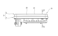
- FIG. 3 is a front view of an electronic control device according to a second embodiment of the present invention.
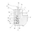
- FIG. 9 is an enlarged view of main parts in a sectional view taken along line DD in FIG. 8;
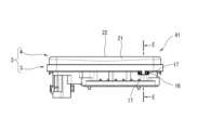
- FIG. 7 is a front view of an electronic control device according to a third embodiment of the present invention.
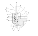
- FIG. 11 is an enlarged view of a main part in a cross-sectional view taken along line EE in FIG. 10;
- FIG. 2 is a cross-sectional view corresponding to the position taken along line FF in FIG. 1;
- FIG. 13 is an enlarged view of section G in FIG. 12.
- FIG. 4 is a front view of an electronic control device according to a fourth embodiment of the present invention.
- FIG. 15 is an enlarged view of main parts in a sectional view taken along line HH in FIG. 14;
- FIG. 1 is a perspective view of an electronic control device 1 according to a first embodiment of the present invention.
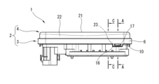
- FIG. 2 is a front view of the electronic control device 1 according to the first embodiment of the present invention.
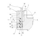
- FIG. 3 is an enlarged view of a main part in a sectional view taken along line AA in FIG.
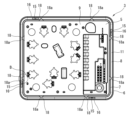
- FIG. 4 is a plan view of the body member 3 of the electronic control device 1 according to the first embodiment of the present invention.
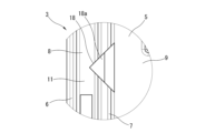
- FIG. 5 is an enlarged view of section B in FIG. 4.
- FIG. 6 is an enlarged view of a main part in a sectional view taken along line CC in FIG.
- the electronic control device 1 is used, for example, in an anti-lock brake system (ABS) for automobiles, a skid prevention system for vehicles, etc., and controls various hydraulic control devices such as hydraulic control solenoids. Specifically, for example, it is interposed between a master cylinder of a vehicle and a wheel cylinder of each wheel, and controls the brake fluid pressure supplied to the wheel cylinder of each wheel based on the wheel speed or the like.
- ABS anti-lock brake system
- the electronic control device 1 has a rectangular parallelepiped-shaped casing 2 in which a circuit board (not shown) on which a large number of electronic components are mounted is housed.
- the casing 2 includes a body member 3 as a first casing and a cover member 4 as a second casing.
- the body member 3 is a dish-shaped molded product made of, for example, a hard synthetic resin material.
- the body member 3 has a rectangular outer shape that is one size larger than the cover member 4 in plan view, and covers one side of the circuit board.
- the body member 3 includes a rectangular body bottom wall 5, a body first outer circumferential wall 6 and a body second outer circumferential wall 7 rising from the outer peripheral edge of the body bottom wall 5, and a body second outer circumferential wall 7.
- a seal groove 8 is formed between the first outer circumferential wall 6 and the second outer circumferential wall 7 of the body.
- the first body outer peripheral wall 6 and the second body outer peripheral wall 7 are located on the outer peripheral side of the circuit board accommodating portion 9 in which the circuit board is stored, and are continuous in an annular manner around the entire outer periphery of the body bottom wall 5. It is formed to do so.
- the body first outer peripheral wall 6 is the outer peripheral wall located on the outermost side of the body member 3, and is formed continuously around the entire outer peripheral edge of the body bottom wall 5.
- the body second outer peripheral wall 7 is an outer peripheral wall located on the inner peripheral side than the body first outer peripheral wall 6, and is formed continuously around the entire outer peripheral edge of the body bottom wall 5.
- the seal groove 8 is a groove having a substantially U-shaped cross section, and is located on the outer peripheral side of the second outer peripheral wall 7 of the body. In other words, the seal groove 8 is located outside the housing position of the circuit board, and is formed so as to continue annularly around the entire outer periphery of the body bottom wall 5. The seal groove 8 is formed outside the second outer peripheral wall 7 of the body and inside the first outer peripheral wall 6 of the body.
- the seal groove 8 is formed between an inner wall surface 8a that is continuous with the outer surface 7a of the second outer peripheral wall 7 of the body, an outer wall surface 8b that is continuous with the inner surface 6a of the first outer peripheral wall 6 of the body, and a wall surface 8b that is continuous with the inner surface 6a of the first outer peripheral wall 6 of the body. and a bottom surface 8c that is continuous to both.
- the seal groove 8 is filled with a thermosetting sealant 10, for example.
- a first connecting portion 15 is formed on the inner wall surface 8a of the seal groove 8. That is, the body member 3 has the first connecting portion 15.
- one first connecting portion 15 is formed on each side of the body member 3.
- each side of the body member 3 is an outline line that constitutes the outline of the body member 3 when viewed from above, and in this embodiment, there are four (four sides).
- the first connecting portion 15 in the first embodiment is a protrusion that protrudes toward the outer circumferential side of the wall surface 8a. Further, the first connecting portion 15 is located within the seal groove 8 .
- the body member 3 has a bag-shaped pocket portion 16 that can accommodate a second connecting portion 25, which will be described later.
- the pocket portion 16 is formed at a position where the first connecting portion 15 is formed, and is a portion where the seal groove 8 is formed deeper than at a position where the first connecting portion 15 is not formed. be. This is because the cover outer circumferential wall 22 (described later) is partially longer in the direction perpendicular to the cover bottom wall 21 (described later) at the position where the second connecting portion 25 (described later) is formed. be.
- the bottom surface of the pocket portion 16 is the bottom surface 8c of the seal groove 8.
- a through hole 17 is formed in the pocket portion 16 of the body member 3 and opens to the outer wall surface 8b of the seal groove 8.
- the body first outer peripheral wall 6 of the body member 3 has the through hole 17 formed at a position facing the first connecting portion 15 .
- This through hole 17 is used, for example, for cutting out a mold for forming the first connecting portion 15. That is, one through hole 17 is formed on each side (four sides) of the body member 3.
- the body member 3 includes a guide rib as a positioning protrusion that guides a cover outer peripheral wall 22 (described later) of the cover member 4 into the seal groove 8 when the cover member 4 is assembled to the body member 3. It has 18.
- the guide rib 18 is formed on the inner wall surface 8a of the seal groove 8 so as to be continuous along the depth direction of the seal groove 8, as shown in FIGS. 4 to 6.
- the guide ribs 18 are formed so as to protrude in the width direction of the seal groove 8 , and the tips protruding into the seal groove 8 form an acute angle continuously along the depth direction of the seal groove 8 .
- the upper surface of the guide rib 18 has, on the seal groove 8 side, an inclined surface 18a whose area increases while being inclined toward the bottom surface 8c of the seal groove 8.
- This inclined surface 18a has a triangular shape in plan view.
- Two guide ribs 18 are formed on each side (four sides) of the body member 3. Note that the guide ribs 18 may not be formed on all sides (four sides) of the body member 3, but may be provided on three different sides of the body member 3. That is, the guide ribs 18 may be provided on a plurality of sides of the body member 3 when the body member 3 is viewed from above.
- the cover member 4 is made of, for example, a press-molded metal plate, a dish-shaped cast product made of aluminum alloy, or the like.
- the cover member 4 has a rectangular outer shape that is slightly smaller than the body member 3 in plan view, and covers one side of the circuit board from the side opposite to the body member 3. As shown in FIGS. 1 to 3, the cover member 4 has a rectangular cover bottom wall 21 and a cover outer peripheral wall 22 as an outer peripheral wall rising from the outer peripheral edge of the cover bottom wall 21.
- the cover outer peripheral wall 22 has, for example, one tongue-shaped protruding wall 23 on each side of the cover member 4, corresponding to the first connecting portion 15.
- the protruding wall 23 corresponds to a leg that protrudes toward the seal groove bottom wall 11, and is formed to protrude from the tip of the cover outer peripheral wall 22 toward the bottom surface 8c of the seal groove 8, as shown in FIG. has been done. That is, the cover member 4 has a protruding wall 23 that protrudes toward the bottom surface 8c of the seal groove 8 (seal groove bottom wall 11) at a part of the tip of the cover outer peripheral wall 22.
- the upper surface of the seal groove bottom wall 11 is the bottom surface 8c.
- the protruding wall 23 is accommodated in the pocket portion 16 of the body member 3 when the cover member 4 is assembled to the body member 3.
- the cover outer peripheral wall 22 has a second connecting portion 25 formed at a position where the protruding wall 23 is formed in the circumferential direction. That is, the cover member 4 has the second connecting portion 25 provided with the cover outer peripheral wall 22.
- the second connecting portion 25 is formed so as to be located within the seal groove 8 when the cover member 4 is assembled to the body member 3.
- the second connecting portion 25 is formed at the tip portion of the cover outer peripheral wall 22 that will be located within the seal groove 8 when the cover member 4 is assembled to the body member 3.
- the second connecting portion 25 in the first embodiment is a through hole formed on the distal end side of the cover outer peripheral wall 22, into which the first connecting portion 15 can enter.
- the second connecting portion 25 in the first embodiment is a recess into which the first connecting portion 15 is caught.
- the first connecting portion 15 in the first embodiment is a protrusion on which the second connecting portion 25 is caught.
- the first connecting portion 15 and the second connecting portion 25 are connected by a snap fit so that the tip of the cover outer peripheral wall 22 does not slip out of the seal groove 8.
- the first connecting portion 15 and the second connecting portion 25 in the first embodiment are connected within the seal groove 8 such that they engage with each other along the direction in which the tip of the cover outer peripheral wall 22 exits the seal groove 8.
- the tip of the protruding wall 23 is in a non-contact state with the bottom surface 8c of the seal groove 8 when the first connecting portion 15 and the second connecting portion 25 are connected.
- FIG. 7 is an enlarged view of a main part of a sectional view corresponding to a position along line AA in FIG.
- the seal groove 8 of the body member 3 and the cover member 4 expands toward the outer circumferential side.
- the amount (bulging amount, protrusion amount) can be suppressed, and the housing 2 can be made smaller overall.
- the cover member 4 can be held on the body member 3 by the connection between the first connecting portion 15 and the second connecting portion 25 until the sealing material 10 is fixed. 10 can be ensured.
- the electronic control device 1 of the first embodiment thermally expands when the sealing material 10 is cured (thermally cured). Therefore, the tip of the cover outer circumferential wall 22 of the cover member 4 easily floats (separates) from the seal groove bottom wall 11 within the seal groove 8 .
- the reaction force of the sealing material 10 and the body member 3 and the cover member 4 increases. That is, in the electronic control device 1 of the first embodiment, the reaction force of the sealing material 10 and the deformation due to thermal expansion of the body member 3 and cover member 4 reduce the bonding force between the first connecting portion 15 and the second connecting portion 25. It acts in the direction of increasing.
- the electronic control device 1 of the first embodiment can reduce the connection strength when the first connecting part 15 and the second connecting part 25 are connected. can be secured.
- the extruded (flowed) sealing material 10 can be received by the pocket portion 16. Therefore, in the electronic control device 1 of the first embodiment, the space between the body member 3 and the cover member 4 is sealed even within the pocket portion 16, and the contact area (creepage Since the distance can be expanded, the seal strength can be improved. In other words, the shortest distance from the inside to the outside of the body member 3 at the contact surface between the body member 3 and the sealing material 10, and the shortest distance from the inside to the outside of the cover member 4 at the contact surface with the sealing material 10 of the cover member 4. It becomes possible to lengthen the distance and improve seal strength.
- FIG. 8 is a front view of an electronic control device 31 according to a second embodiment of the present invention.
- FIG. 9 is an enlarged view of a main part in a sectional view taken along line DD in FIG.
- the electronic control device 31 of the second embodiment has substantially the same configuration as the electronic control device 1 of the first embodiment described above, but a bottom wall through hole 32 is formed in the seal groove bottom wall 11 of the body member 3. , the protruding wall 23 and the second connecting portion 25 pass through the bottom wall through hole 32 .
- the second connecting portion 25 is connected to the first connecting portion 15 formed below the seal groove 8 .
- the first connecting portion 15 of the second embodiment is formed below the seal groove 8.
- the first connecting portion 15 of the second embodiment is formed directly below the seal groove 8. More specifically, the first connecting portion 15 of the second embodiment is formed at a position so as to overlap the seal groove 8 when the body member 3 is viewed from above.
- the second connecting portion 25 of the second embodiment penetrates through the bottom wall through hole 32 and is connected to the first connecting portion 15 so that the tip of the cover outer peripheral wall 22 does not come out of the seal groove 8.
- the first connecting portion 15 and the second connecting portion 25 in the second embodiment are snap-fitted directly below the seal groove 8 so that the tip of the cover outer circumferential wall 22 is caught on each other along the direction in which the cover outer peripheral wall 22 comes out of the seal groove 8. are connected by.
- the first connecting portion 15 of the second embodiment is a projection formed to protrude from the side surface of the body bottom wall 5 located below the seal groove 8 toward the outer peripheral side of the body member 3.
- the pocket portion 16 is not set in the body member 3, and the bottom surface 8c of the seal groove 8 is formed so as to be located on the same plane over the entire circumference. . That is, in the electronic control device 31 of the second embodiment, the seal groove 8 is formed to have the same depth over the entire circumference.
- the electronic control device 31 of the second embodiment has a more complicated shape than the first embodiment due to the bottom wall through hole 32 being formed in the seal groove bottom wall 11 of the body member 3, it has the same features as described above. It is possible to achieve substantially the same effects as the electronic control device 1 of the first embodiment.
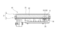
- FIG. 10 is a front view of an electronic control device 41 according to a third embodiment of the present invention.
- FIG. 11 is an enlarged view of a main part in a sectional view taken along line EE in FIG.
- FIG. 12 is a cross-sectional view corresponding to the position along line FF in FIG.
- FIG. 13 is an enlarged view of section G in FIG. 12.
- the electronic control device 41 of the third embodiment has substantially the same configuration as the electronic control device 1 of the first embodiment described above, but a bottom wall through hole 32 formed in the seal groove bottom wall 11 of the body member 3 serves as a first connecting portion 15, and a second connecting portion 25 is formed at the tip of the cover outer peripheral wall 22 of the cover member 4.
- the second connecting portion 25 of the third embodiment includes a pair of first protruding pieces 42 that protrude from the tip of the cover outer peripheral wall 22 toward the first connecting portion 15 (bottom wall through hole 32), and a pair of first protruding pieces A pair of second protruding pieces 43 protrude from the tip of the piece 42.
- the pair of second protruding pieces 43 are formed to protrude in opposite directions along the circumferential direction of the cover member 4.
- the second connecting portion 25 of the third embodiment is connected to the first connecting portion 15 by the pair of second protruding pieces 43 being caught on the opening edge of the first connecting portion 15 (bottom wall through hole 32).
- the first connecting portion 15 and the second connecting portion 25 in the third embodiment are connected by snap fit so that they are engaged with each other along the direction in which the tip of the cover outer peripheral wall 22 exits from the seal groove 8.
- the pocket portion 16 is set so as to cover the connecting portion between the first connecting portion 15 and the second connecting portion 25.
- the electronic control device 41 of the third embodiment can achieve substantially the same effects as the electronic control device 1 of the first embodiment described above.
- the electronic control device 41 of the third embodiment can structurally make the first connecting portion 15 (bottom wall through hole 32) smaller than the electronic control device 31 of the second embodiment described above. Become. Therefore, in the electronic control device 41 of the third embodiment, compared to the electronic control device 31 of the second embodiment, the sealing material 10 flowing out from the seal groove 8 through the first connecting portion 15 (bottom wall through hole 32) The outflow amount is relatively reduced, and the seal strength within the seal groove can be relatively improved.
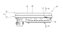
- FIG. 14 is a front view of an electronic control device 51 according to a fourth embodiment of the present invention.
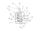
- FIG. 15 is an enlarged view of essential parts in a sectional view taken along line HH in FIG. 14.
- the electronic control device 51 of the fourth embodiment has substantially the same configuration as the electronic control device 1 of the first embodiment described above, except that the first connecting portion 15 is formed on the inner wall surface 8a of the seal groove 8.
- This is a concave portion
- the second connecting portion 25 is a protrusion formed by bending a part of the tip of the cover outer peripheral wall 22 inward (inner peripheral side) of the cover member 4 .
- the second connecting portion 25 of the fourth embodiment is formed by bending a part of the tip of the cover outer peripheral wall 22 toward the inner wall surface 8a of the seal groove 8 so as to be caught in the recessed portion that is the first connecting portion 15. Ru.
- the second connecting portion 25 of the fourth embodiment is formed by bending the protruding wall 23 toward the inner wall surface 8a of the seal groove 8.
- the second connecting portion 25 of the fourth embodiment is connected to the first connecting portion 15 by being caught on the first connecting portion 15. That is, the first connecting portion 15 and the second connecting portion 25 in the fourth embodiment are connected by snap fit so that they are engaged with each other along the direction in which the tip of the cover outer peripheral wall 22 comes out of the seal groove 8.
- the pocket portion 16 is not set in the body member 3, and the bottom surface 8c of the seal groove 8 is formed so as to be located on the same plane over the entire circumference. . That is, in the electronic control device 51 of the fourth embodiment, the seal groove 8 is formed to have the same depth over the entire circumference.
- the electronic control device 51 of the fourth embodiment can achieve substantially the same effects as the electronic control device 1 of the first embodiment described above.
- the electronic control device 51 of the fourth embodiment can simplify the shape of the second connecting portion 25 of the cover member 4.
- the length of the outer peripheral wall 22 of the cover is formed to be partially longer in the direction perpendicular to the cover bottom wall 21 at the position where the second connecting portion 25 is formed, and
- the pocket portion 16 may be formed at the position where the portion 15 is formed.
- the body member 3 may be provided with guide ribs 18 at the positions where the first connecting portions 15 are provided.
- the second connecting portion 25 may be a recess into which the first connecting portion 15 is caught, instead of being a through hole.
Landscapes
- Engineering & Computer Science (AREA)
- Microelectronics & Electronic Packaging (AREA)
- Casings For Electric Apparatus (AREA)
Abstract
Description
なお、電子制御装置は、上記シール溝よりも下方に第1連結部を形成し、上記第2連結部が上記シール溝のシール溝底壁に形成された底壁貫通孔を突き抜けて上記外周壁の先端が上記シール溝から抜け出さないように上記第1連結部と連結するようにしてもよい。
Claims (13)
- 電子部品が実装された回路基板を収容する筐体を有し、
上記筐体は、上記回路基板の片面を覆う第1筐体と、該第1筐体とは反対側から上記回路基板の片面を覆う第2筐体と、を有し、
上記第1筐体は、上記回路基板の収容位置よりも外側に位置してシール材が充填されるシール溝と、当該シール溝内に設けられた第1連結部と、を有し、
上記第2筐体は、先端が上記シール溝に挿入される外周壁と、当該外周壁に設けられた第2連結部と、を有し、
上記第2連結部は、上記シール溝内で上記外周壁の先端が上記シール溝から抜け出さないように上記第1連結部と連結していることを特徴とする電子制御装置。 - 電子部品が実装された回路基板を収容する筐体を有し、
上記筐体は、上記回路基板の片面を覆う第1筐体と、該第1筐体とは反対側から上記回路基板の片面を覆う第2筐体と、を有し、
上記第1筐体は、上記回路基板の収容位置よりも外側に位置してシール材が充填されるシール溝と、当該シール溝よりも下方に形成された第1連結部と、を有し、
上記第2筐体は、先端が上記シール溝に挿入される外周壁と、当該外周壁に設けられた第2連結部と、を有し、
上記第2連結部は、上記シール溝のシール溝底壁に形成された底壁貫通孔を突き抜け、上記外周壁の先端が上記シール溝から抜け出さないように上記第1連結部と連結していることを特徴とする電子制御装置。 - 上記第1筐体は、上記第2連結部を収容可能な袋状のポケット部を有することを特徴とする請求項1に記載の電子制御装置。
- 上記第1連結部は、上記第1筐体から当該第1筐体の外周側に向かって突出する突起であり、
上記第2連結部は、上記突起が引っかかる凹部であることを特徴とする請求項1または2に記載の電子制御装置。 - 上記第1連結部は、上記シール溝の側壁から当該第1筐体の外周側に向かって突出する突起であり、
上記第2連結部は、上記突起が引っかかる凹部であることを特徴とする請求項1に記載の電子制御装置。 - 上記第2筐体は、上記外周壁の先端の一部に上記シール溝のシール溝底壁に向かって突出する脚部を有し、上記脚部が上記シール溝底壁に接触することで、上記脚部が設けられていない上記外周壁の先端は、上記シール溝底壁と非接触状態になることを特徴とする請求項5に記載の電子制御装置。
- 上記第2連結部は、スナップフィットにより上記第1連結部と連結していることを特徴とする請求項1または2に記載の電子制御装置。
- 上記第1連結部は、上記シール溝底壁に形成された上記底壁貫通孔であり、
上記第2連結部は、上記第2筐体の上記外周壁の先端から上記底壁貫通孔に向かって突出する一対の第1突出片と、上記一対の第1突出片の先端から突出する一対の第2突出片と、を有し、
上記一対の第2突出片は、上記筐体の周方向に、互いに反対方向に突出するよう形成され、
上記第2連結部は、上記一対の第2突出片が上記底壁貫通孔の開口縁に引っかかることで上記第1連結部と連結していることを特徴とする請求項2に記載の電子制御装置。 - 上記第1連結部は、上記シール溝の側壁に形成された凹部であり、
上記第2連結部は、上記凹部に引っかかるように、上記第2筐体の上記外周壁の先端の一部を上記シール溝の上記凹部が形成された側の側壁側に折り曲げることで形成された突出部であることを特徴とする請求項1に記載の電子制御装置。 - 上記シール溝の側壁に、上記シール溝の深さ方向に沿って形成されるとともに、上記シール溝内に突出した先端が鋭角となった位置決め突起が形成されていることを特徴とする請求項1または2に記載の電子制御装置。
- 上記筐体は直方体形状を呈し、
上記位置決め突起は、上記第1筐体の平面視で当該第1筐体の異なる3辺にそれぞれ設けられていることを特徴とする請求項10に記載の電子制御装置。 - 上記位置決め突起の上面は、上記シール溝側に、上記シール溝の底壁側に向かって傾斜しつつ面積が拡大する傾斜面を有することを特徴とする請求項10に記載の電子制御装置。
- 上記第1連結部が設けられた位置には、上記位置決め突起が設けられていることを特徴とする請求項10に記載の電子制御装置。
Priority Applications (2)
| Application Number | Priority Date | Filing Date | Title |
|---|---|---|---|
| DE112023003613.6T DE112023003613T5 (de) | 2022-08-31 | 2023-08-30 | Elektronische Steuervorrichtung |
| JP2024544313A JP7898526B2 (ja) | 2022-08-31 | 2023-08-30 | 電子制御装置 |
Applications Claiming Priority (2)
| Application Number | Priority Date | Filing Date | Title |
|---|---|---|---|
| JP2022-137426 | 2022-08-31 | ||
| JP2022137426 | 2022-08-31 |
Publications (1)
| Publication Number | Publication Date |
|---|---|
| WO2024048624A1 true WO2024048624A1 (ja) | 2024-03-07 |
Family
ID=90099671
Family Applications (1)
| Application Number | Title | Priority Date | Filing Date |
|---|---|---|---|
| PCT/JP2023/031388 Ceased WO2024048624A1 (ja) | 2022-08-31 | 2023-08-30 | 電子制御装置 |
Country Status (3)
| Country | Link |
|---|---|
| JP (1) | JP7898526B2 (ja) |
| DE (1) | DE112023003613T5 (ja) |
| WO (1) | WO2024048624A1 (ja) |
Families Citing this family (1)
| Publication number | Priority date | Publication date | Assignee | Title |
|---|---|---|---|---|
| DE102024212118A1 (de) * | 2024-12-18 | 2026-06-18 | Robert Bosch Gesellschaft mit beschränkter Haftung | Deckelteil, Gehäuse, Bremsdruckerzeuger, Bremssystem und Fahrzeug |
Citations (8)
| Publication number | Priority date | Publication date | Assignee | Title |
|---|---|---|---|---|
| JP2002221209A (ja) * | 2001-01-26 | 2002-08-09 | Kojima Press Co Ltd | 固定ノブの固定構造 |
| JP2007043870A (ja) * | 2005-08-05 | 2007-02-15 | Yazaki Corp | アンダーケースおよびプロテクタ |
| JP2009117674A (ja) * | 2007-11-08 | 2009-05-28 | Mitsubishi Electric Corp | 筐体装置 |
| JP2011204974A (ja) * | 2010-03-26 | 2011-10-13 | Keihin Corp | 電子制御装置 |
| JP2013004551A (ja) * | 2011-06-13 | 2013-01-07 | Denso Corp | 電子制御装置 |
| JP2013193719A (ja) * | 2012-03-23 | 2013-09-30 | Hitachi Automotive Systems Ltd | 電子制御装置 |
| JP2013545173A (ja) * | 2010-10-12 | 2013-12-19 | ツリーフロッグ ディベロップメンツ インコーポレイテッド | 物品を収容する筐体 |
| CN113453476A (zh) * | 2021-06-29 | 2021-09-28 | 成都千嘉科技有限公司 | 一种局部灌封防水结构及方法 |
-
2023
- 2023-08-30 JP JP2024544313A patent/JP7898526B2/ja active Active
- 2023-08-30 WO PCT/JP2023/031388 patent/WO2024048624A1/ja not_active Ceased
- 2023-08-30 DE DE112023003613.6T patent/DE112023003613T5/de active Pending
Patent Citations (8)
| Publication number | Priority date | Publication date | Assignee | Title |
|---|---|---|---|---|
| JP2002221209A (ja) * | 2001-01-26 | 2002-08-09 | Kojima Press Co Ltd | 固定ノブの固定構造 |
| JP2007043870A (ja) * | 2005-08-05 | 2007-02-15 | Yazaki Corp | アンダーケースおよびプロテクタ |
| JP2009117674A (ja) * | 2007-11-08 | 2009-05-28 | Mitsubishi Electric Corp | 筐体装置 |
| JP2011204974A (ja) * | 2010-03-26 | 2011-10-13 | Keihin Corp | 電子制御装置 |
| JP2013545173A (ja) * | 2010-10-12 | 2013-12-19 | ツリーフロッグ ディベロップメンツ インコーポレイテッド | 物品を収容する筐体 |
| JP2013004551A (ja) * | 2011-06-13 | 2013-01-07 | Denso Corp | 電子制御装置 |
| JP2013193719A (ja) * | 2012-03-23 | 2013-09-30 | Hitachi Automotive Systems Ltd | 電子制御装置 |
| CN113453476A (zh) * | 2021-06-29 | 2021-09-28 | 成都千嘉科技有限公司 | 一种局部灌封防水结构及方法 |
Also Published As
| Publication number | Publication date |
|---|---|
| JPWO2024048624A1 (ja) | 2024-03-07 |
| JP7898526B2 (ja) | 2026-07-31 |
| DE112023003613T5 (de) | 2025-06-12 |
Similar Documents
| Publication | Publication Date | Title |
|---|---|---|
| CN113853837B (zh) | 电子控制装置 | |
| US9848501B2 (en) | Electronic control device | |
| JPH08222007A (ja) | 車両の前照灯 | |
| KR101575265B1 (ko) | 고정 부재를 이용한 차량의 전자 제어 장치 및 그 제조 방법 | |
| CN109690126B (zh) | 防振装置 | |
| JP6871284B2 (ja) | 樹脂成形体 | |
| JP5758645B2 (ja) | グロメット | |
| JP7114918B2 (ja) | 電子制御装置 | |
| JP6900246B2 (ja) | ガスケット | |
| JP2019220256A (ja) | コネクタ | |
| JP5609779B2 (ja) | 電子制御装置 | |
| JP4473644B2 (ja) | モータの防水構造 | |
| JP6652312B1 (ja) | 電子制御装置 | |
| JP5345871B2 (ja) | 電気接続箱 | |
| JP2012175718A (ja) | グロメット | |
| WO2014203683A1 (ja) | エアバッグ装置 | |
| JP2018154178A (ja) | 車両用ランプ取付構造 | |
| JP2018069864A (ja) | コラムホールカバー | |
| JP6874657B2 (ja) | 車両のブリーザプラグ | |
| JP7641369B2 (ja) | 自動車用制御装置 | |
| CN109204122B (zh) | 车身构造 | |
| JP2014204530A (ja) | グロメット及びワイヤーハーネス | |
| JP2019088155A (ja) | グロメットおよびグロメット取付構造 | |
| JP6054703B2 (ja) | 中空部品の組付構造 | |
| JP7241496B2 (ja) | 密封装置 |
Legal Events
| Date | Code | Title | Description |
|---|---|---|---|
| 121 | Ep: the epo has been informed by wipo that ep was designated in this application |
Ref document number: 23860386 Country of ref document: EP Kind code of ref document: A1 |
|
| WWE | Wipo information: entry into national phase |
Ref document number: 2024544313 Country of ref document: JP |
|
| WWE | Wipo information: entry into national phase |
Ref document number: 112023003613 Country of ref document: DE |
|
| WWP | Wipo information: published in national office |
Ref document number: 112023003613 Country of ref document: DE |
|
| 122 | Ep: pct application non-entry in european phase |
Ref document number: 23860386 Country of ref document: EP Kind code of ref document: A1 |