WO2024047941A1 - 建物壁の交差部構造 - Google Patents
建物壁の交差部構造 Download PDFInfo
- Publication number
- WO2024047941A1 WO2024047941A1 PCT/JP2023/016807 JP2023016807W WO2024047941A1 WO 2024047941 A1 WO2024047941 A1 WO 2024047941A1 JP 2023016807 W JP2023016807 W JP 2023016807W WO 2024047941 A1 WO2024047941 A1 WO 2024047941A1
- Authority
- WO
- WIPO (PCT)
- Prior art keywords
- wall
- stud
- studs
- intersection
- attached
- Prior art date
- Legal status (The legal status is an assumption and is not a legal conclusion. Google has not performed a legal analysis and makes no representation as to the accuracy of the status listed.)
- Ceased
Links
Images




Classifications
-
- E—FIXED CONSTRUCTIONS
- E04—BUILDING
- E04B—GENERAL BUILDING CONSTRUCTIONS; WALLS, e.g. PARTITIONS; ROOFS; FLOORS; CEILINGS; INSULATION OR OTHER PROTECTION OF BUILDINGS
- E04B2/00—Walls, e.g. partitions, for buildings; Wall construction with regard to insulation; Connections specially adapted to walls
- E04B2/74—Removable non-load-bearing partitions; Partitions with a free upper edge
-
- E—FIXED CONSTRUCTIONS
- E04—BUILDING
- E04B—GENERAL BUILDING CONSTRUCTIONS; WALLS, e.g. PARTITIONS; ROOFS; FLOORS; CEILINGS; INSULATION OR OTHER PROTECTION OF BUILDINGS
- E04B2/00—Walls, e.g. partitions, for buildings; Wall construction with regard to insulation; Connections specially adapted to walls
- E04B2/74—Removable non-load-bearing partitions; Partitions with a free upper edge
- E04B2/7407—Removable non-load-bearing partitions; Partitions with a free upper edge assembled using frames with infill panels or coverings only; made-up of panels and a support structure incorporating posts
- E04B2/7409—Removable non-load-bearing partitions; Partitions with a free upper edge assembled using frames with infill panels or coverings only; made-up of panels and a support structure incorporating posts special measures for sound or thermal insulation, including fire protection
-
- E—FIXED CONSTRUCTIONS
- E04—BUILDING
- E04B—GENERAL BUILDING CONSTRUCTIONS; WALLS, e.g. PARTITIONS; ROOFS; FLOORS; CEILINGS; INSULATION OR OTHER PROTECTION OF BUILDINGS
- E04B2/00—Walls, e.g. partitions, for buildings; Wall construction with regard to insulation; Connections specially adapted to walls
- E04B2/74—Removable non-load-bearing partitions; Partitions with a free upper edge
- E04B2/76—Removable non-load-bearing partitions; Partitions with a free upper edge with framework or posts of metal
Definitions
- the present disclosure relates to a building wall intersection structure.
- studs For dry partition walls, including parting walls, multiple studs (or studs) are erected at intervals in the longitudinal direction of a pair of upper and lower runners, and a facing material such as gypsum board is installed on both sides of each stud. It is formed by attaching.
- the partition wall separates two rooms.
- Patent Document 1 In a double-sided structure where panels are attached to both sides of each stud that makes up a dry partition wall, the formation of a so-called sound bridge makes it easier for sound to propagate (leak) from one living room to the other, resulting in poor sound insulation.
- a single-sided structure may be used in which adjacent studs are arranged in a staggered manner and a facing material is attached to one side of each stud.
- Patent Document 1 an example is proposed in Patent Document 1.
- the sound-insulating partition wall disclosed in Patent Document 1 is a partition wall formed by doubly fixing wall boards through studs and filling a hollow layer between the wall boards with a sound-insulating material.
- One side of the wall board is in contact with one side of the stud, a gap is provided between the other side of the stud and the other side of the wall board, the studs are arranged in a staggered manner between the wall boards, and the hollow layer and the stud and Sound insulating material is installed in the gap between the wall board and the wall board.
- FIG. 1 shows an example of the structure of a partition wall, such as the partition wall described in Patent Document 1, in which a facing material is attached to one side of the stud.
- FIG. 1 is a cross-sectional view of an example of a conventional partition wall.
- the illustrated example mainly shows an intersection 70 where the first wall 30, which is a partition wall, and the second wall 60, which is a partition wall or an outer wall, intersect in a T-shape in plan view.
- the first wall 30 has a staggered arrangement in which a plurality of first A studs 20A and a plurality of first B studs 20B are arranged at intervals with respect to the horizontal longitudinal direction and are alternately shifted in a direction perpendicular to the horizontal longitudinal direction.
- the first surface material 10A is attached to one side of the plurality of first A studs 20A
- the second surface material 10B is attached to one side of the plurality of first B studs 20B.
- the first panel 10A is a layered structure of an underlay 11A formed by a plurality of underlay panels and an upper panel 12A formed by a plurality of top panels, one of which is arranged horizontally and the other is arranged vertically. It is located.
- the second panel 10B is a layered structure of an underlay 11B formed by a plurality of lower panel materials and an upper panel 12B formed by a plurality of upper panel materials, one of which is arranged horizontally and the other. are arranged vertically.
- the underlays 11A and 11B are both fastened to the corresponding studs 20A and 20B with fasteners 25 such as screws, and the overlays 12A and 12B are fastened to the underlays 11A and 11B with adhesive, staples, etc. ing.
- this hollow 15 ensures sound insulation and heat insulation. Moreover, in order to further improve the sound insulation performance, there is also a form in which the hollow 15 is filled with a sound insulation material.
- the second wall 60 has a staggered arrangement in which a plurality of second A studs 50A and a plurality of second B studs 50B are arranged at intervals in the horizontal longitudinal direction and alternately shifted in a direction perpendicular to the horizontal longitudinal direction.
- the third surface material 40A is attached to one side of the plurality of second A studs 50A
- the fourth surface material 40B is attached to one side of the plurality of second B studs 50B.
- the third panel 40A is a layered structure of an underlay 41A formed by a plurality of lower panel materials and an upper panel 42A formed by a plurality of upper panel materials, one of which is arranged horizontally and the other is arranged vertically. It is located.
- the fourth panel 40B is a layered structure of an underlay 41B formed by a plurality of lower panel materials and an upper panel 42B formed by a plurality of upper panel materials, one of which is arranged horizontally and the other. are arranged vertically.
- the underlays 41A, 41B are both fastened to the corresponding studs 50A, 50B with fasteners 25 such as screws, and the overlays 42A, 42B are fastened to the underlays 41A, 41B with adhesive, staples, etc. ing.
- this hollow 45 ensures sound insulation and heat insulation. Further, in order to further improve the sound insulation performance, there is also a form in which the hollow 45 is filled with a sound insulation material.
- a building wall intersection structure 90 is formed at the intersection 70 where the first wall 30 and the second wall 60 intersect in a T-shape in plan view.
- the two corner portions 72 face the two living rooms R1 and R2, respectively.
- a vertical (vertical) slit 55 is provided at the intersection 70 in order to prevent sound from propagating through the underlay 41A of the third panel 40A constituting the second wall 60. ing.
- the present disclosure provides a building wall intersection structure that is excellent in both sound insulation and earthquake resistance.
- a building wall intersection structure includes: A building wall intersection structure having an intersection where a first wall and a second wall intersect in a T-shape in plan view,
- the first wall includes a plurality of first A studs and first B studs alternately spaced apart in the horizontal longitudinal direction, a first panel is attached to one side of the plurality of first A studs, It is formed by attaching the second surface material to one side of the 1B stud,
- the second wall includes a plurality of second A studs and second B studs alternately spaced apart in the horizontal longitudinal direction, a third panel is attached to one side of the plurality of second A studs, and a third wall member is attached to one side of the plurality of second A studs, It is formed by attaching the fourth side material to one side of the 2B stud, At one first corner of the two corners of the intersection, the first A stud to which the first face material is attached is arranged, and the second A stud to which the third face material is attached.
- the studs are placed At the other second corner of the two corners of the intersection, the first B stud to which the second surface material is attached is not arranged, and the third surface material is attached.
- the second A stud is arranged;
- a reinforcing plate spans both the inner surface of the second face material and the second A stud, and the reinforcing plate is fixed to both the second face material and the second A stud.
- a building wall intersection structure includes: A building wall intersection structure having an intersection where a first wall and a second wall intersect in a cross shape in plan view,
- the first wall includes a plurality of first A studs and first B studs alternately spaced apart in the horizontal longitudinal direction, a first panel is attached to one side of the plurality of first A studs, It is formed by attaching the second surface material to one side of the 1B stud,
- the second wall includes a plurality of second A studs and second B studs alternately spaced apart in the horizontal longitudinal direction, a third panel is attached to one side of the plurality of second A studs, and a third wall member is attached to one side of the plurality of second A studs, It is formed by attaching the fourth side material to one side of the 2B stud, At a first corner of the four corners of the intersection, the first A stud to which the first face material is attached is arranged, and the second A stud to which the third face material is attached is
- the first B stud to which the second surface material is attached is not arranged, and the first B stud to which the third surface material is attached is not located.
- 2A studs are placed, At the third corner of the four corners of the intersection, the second B stud to which the fourth surface material is attached is arranged, and the first A stud to which the first surface material is attached is arranged. not placed, At the fourth corner of the four corners of the intersection, the first B stud to which the second surface material is attached is arranged, and the second B stud to which the fourth surface material is attached is arranged.
- a reinforcing plate straddles both the inner surface of the third panel and the first A stud, and the reinforcing plate is fixed to both the third panel and the first A stud
- a reinforcing plate straddles both the inner surface of the second face material and the second A stud, and the reinforcing plate is fixed to both the second face material and the second A stud
- a reinforcing plate straddles both the inner surface of the first face material and the second B stud, and the reinforcing plate is fixed to both the first face material and the second B stud
- a reinforcing plate spans both the inner surface of the fourth panel and the first B stud, and the reinforcing plate is fixed to both the fourth panel and the first B stud.
- FIG. 2 is a cross-sectional view of an example of a conventional building wall intersection structure (Comparative Example 1).
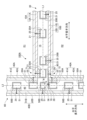
- FIG. 2 is a cross-sectional view of an example of the intersection structure of building walls according to the first embodiment.
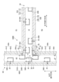
- FIG. 3 is a cross-sectional view of another example of the building wall intersection structure according to the first embodiment.
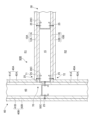
- FIG. 7 is a cross-sectional view of another example of the building wall intersection structure according to the second embodiment.
- FIG. 7 is a cross-sectional view of another example of the intersection structure of building walls according to the third embodiment.
- FIG. 7 is a cross-sectional view of a modification of the building wall intersection structure according to the third embodiment.
- It is a cross-sectional view of another example (comparative example 2) of the intersection structure of the conventional building wall.
- It is a cross-sectional view of still another example (comparative example 3) of the intersection part structure of the conventional building wall.
- FIG. 2 is a cross-sectional view of an example of the building wall intersection structure according to the first embodiment
- FIG. 3 is a cross-sectional view of another example of the building wall intersection structure according to the first embodiment. It is a front view.
- intersection structure of building walls in the illustrated example is a double-sided double-walled wall in which each wall has an overlapping layer consisting of two layers of underlayment and toplayer, but each wall has three or more layers on both sides.
- the wall may have a layered surface material, or it may have one surface material (one layer) attached to both sides.
- the building wall intersection structure 100 shown in FIG. 2 is applied to steel-frame buildings, RC (Reinforced Concrete) buildings, wooden buildings, etc. It also includes factories, warehouses, etc.
- intersection structure 100 is an intersection structure having an intersection 70 where the first wall 30 and the second wall 60 intersect in a T-shape in plan view.
- Both the first wall 30 and the second wall 60 have a lower runner (or floor runner) and an upper runner (or ceiling runner) (not shown) that extend in the lateral direction (horizontal direction), and are connected to the upper and lower runners.
- the upper and lower ends of studs 20A, 20B, 50A, and 50B extending in the longitudinal direction (vertical direction) are attached.
- Both the upper runner and the lower runner are formed of lightweight steel frames such as channel steel, and the upper runner is attached to the floor structure (not shown) above with the opening facing downward, and the lower runner is attached with the opening facing upward. It is attached to a floor structure (not shown) below in an orientation facing towards.
- the studs 20A, 20B, 50A, and 50B are formed of lipped channel steel of lightweight steel, but may also be formed of channel steel or square steel pipes.
- a plurality of horizontally extending steady rests may be provided at a predetermined pitch (eg, 1200 mm pitch) in the height direction of the studs 20A, 20B, 50A, and 50B.
- the upper runner, lower runner, and studs 20A, 20B, 50A, and 50B are, for example, lightweight steel frames with a thickness of 0.4 mm or more, and are made of steel specified in JIS A 6517 ("Steel base material for construction"). Steel runners and steel studs, or equivalent, compliant or compatible products are applicable.
- a plurality of studs 20A, 20B, 50A, 50B are arranged between the lower runner and the upper runner at intervals of 606 mm or less (for example, 606 mm, 455 mm) in the horizontal longitudinal direction of the wall. They are built at intervals.
- the studs 20A, 20B, 50A, and 50B in the illustrated example can be of type 65 (65 mm x 45 mm x 0.8 mm) or type 75 (75 mm x 45 mm x 0.8 mm), and may be of type 50 (50 mm x 0.8 mm).
- 45 mm x 0.8 mm), 90 type (90 mm x 45 mm x 0.8 mm), and 100 type (100 mm x 45 mm x 0.8 mm) may be applied.
- the first wall 30 has a staggered arrangement in which a plurality of first A studs 20A and a plurality of first B studs 20B are arranged at intervals with respect to the horizontal longitudinal direction and are alternately shifted in a direction perpendicular to the horizontal longitudinal direction.
- the first surface material 10A is attached to one side of the plurality of first A studs 20A
- the second surface material 10B is attached to one side of the plurality of first B studs 20B.
- the first panel 10A is a layered structure of an underlay 11A formed by a plurality of underlay panels and an upper panel 12A formed by a plurality of top panels, one of which is arranged horizontally and the other is arranged vertically. It is located.
- the second panel 10B is a layered structure of an underlay 11B formed by a plurality of lower panel materials and an upper panel 12B formed by a plurality of upper panel materials, one of which is arranged horizontally and the other. are arranged vertically.
- the underlays 11A and 11B are respectively fastened to studs 20A and 20B with fasteners 25 such as screws, and the top sheets 12A and 12B are fastened to the underlays 11A and 11B using adhesives, staples, and the like.
- the hollow 15 there is a hollow 15 inside the first wall 30, and this hollow 15 ensures sound insulation and heat insulation. Further, in order to further improve the sound insulation performance, the hollow space 15 may be filled with a sound insulation material (including a sound absorption material and a sound insulation material) such as glass wool or rock wool.
- a sound insulation material including a sound absorption material and a sound insulation material
- the second wall 60 has a staggered arrangement in which a plurality of second A studs 50A and a plurality of second B studs 50B are arranged at intervals in the horizontal longitudinal direction and alternately shifted in a direction orthogonal to the horizontal longitudinal direction.
- the third surface material 40A is attached to one side of the plurality of second A studs 50A
- the fourth surface material 40B is attached to one side of the plurality of second B studs 50B.
- the third panel 40A is a layered structure of an underlay 41A formed by a plurality of underlay panels and an upper panel 42A formed by a plurality of top panels, one of which is arranged horizontally and the other is arranged vertically. It is located.
- the fourth panel 40B is a layered structure of an underlay 41B formed by a plurality of lower panel materials and an upper panel 42B formed by a plurality of upper panel materials, one of which is arranged horizontally and the other. are arranged vertically.
- the underlays 41A, 41B are respectively attached to studs 50A, 50B with fasteners 25 such as screws, and the upper sheets 42A, 42B are fastened to the underlays 41A, 41B with adhesive, staples, etc.
- the hollow 45 there is a hollow 45 inside the second wall 60, and this hollow 45 ensures sound insulation and heat insulation. Further, in order to further improve the sound insulation performance, the hollow space 45 may be filled with a sound insulation material such as glass wool or rock wool.
- An intersection structure 100 is formed at an intersection 70 where the first wall 30 and the second wall 60 intersect in a T-shape in plan view, and a first corner 71 and a second corner of two inside corners of the intersection 70 are formed. 72 respectively face two living rooms R1 and R2.
- a wide slit is provided at the intersection 70 extending in the vertical direction. 56 are provided.
- Gypsum board, gypsum board, calcium silicate board, particle board, hardboard, plywood, structural plywood, etc. are used as the underlay surface material forming the underlayment 11A, 11B, 41A, and 41B. Among them, gypsum board and gypsum board is preferably used.
- a gypsum board, a gypsum board, a calcium silicate board, etc. are applied to the top facing material forming the top linings 12A, 12B, 42A, and 42B, and among them, a gypsum board and a gypsum board are preferably used.
- gypsum board includes reinforced gypsum board, ordinary rigid gypsum board, sheathing rigid gypsum board, moisture absorbing and desorbing reinforced gypsum board, moisture absorbing and desorbing ordinary gypsum board, moisture absorbing and desorbing sheathing rigid gypsum board, and glass fiber. Includes non-woven gypsum board, glass mat gypsum board, etc.
- the first wall 30 is a partition wall that partitions the living rooms R1 and R2.
- the second wall 60 may be a separate partition wall that forms living rooms R1 and R2 together with the first wall 30, or may be an outer wall.
- the flat reinforcing plate 80 (an example of a reinforcing plate) straddles both the inner surface of the second face material 10B and the second A stud 50A forming the second wall 60, and It is fixed to both sides by fasteners 28 such as screws.
- the flat reinforcing plate 80 has a length in the vertical direction of the second face material 10B and the second A stud 50A, and is a single long piece. and is fixed by a plurality of fasteners 28 at predetermined intervals in the vertical direction. In addition, a plurality of relatively short flat reinforcing plates 80 are applied, and a plurality of flat reinforcing plates 80 are intermittently arranged for each of the second face material 10B and the second A stud 50A. may be set and fixed.
- the fixing position of the flat reinforcing plate 80 to the second face material 10B and the second A stud 50A by the fasteners 28 is provided as close to the second corner 72 as possible. This is preferable because the distance to each fastener 28 when the second corner 72 is used as a fulcrum can be shortened, and the pulling force due to the bending moment that can act on each fastener 28 can be reduced. In order to be as close as possible to the second corner 72 and to ensure good fastening properties, the fixing position by the fastener 28 can be set at a position approximately 10 to 15 mm away from the second corner 72.
- the second corner 72 where the second panel 10B is not supported by the first B stud 20B is reinforced by the flat reinforcing plate 80, thereby improving sound insulation and earthquake resistance. This creates an intersection structure that is excellent for both sides.
- the flat reinforcing plate 80 may be fixed to both the second A stud 50A and the first B stud 20B with the fasteners 28. Further, stoppers may be attached to the upper and lower runners (not shown) so as to suppress movement of the flat reinforcing plate 80. Further, the flat reinforcing plate 80 may be sandwiched between upper and lower runners (not shown) and spacers installed on the upper and lower runners. Furthermore, by bringing the end face of the underlaying surface material 11B into contact with the second A stud 50A without intervening the underlayment surface material 41A, the fastening position of the fastener 28 for fastening the flat reinforcing plate 80 to the underlayment surface material 11B is changed to the second A stud 50A. It may be located even closer to the 2A stud 50A.
- the building wall intersection structure 100A shown in FIG. 3 differs from the intersection structure 100 in the following points. That is, in the first wall 30, both the first A stud 20A and the first B stud 20B are arranged at the wall core L1, and the first face material 10A and the second face material 10B are attached alternately through the paving boards 21. It is being In addition, in the second wall 60, both the second A stud 50A and the second B stud 50B are arranged at the wall core L2, and the third surface material 40A and the fourth surface material 40B are attached alternately through the sill board 51. It is being
- the second corner 72 where the second panel 10B is not supported by the first B stud 20B is reinforced by the flat reinforcing plate 80, which provides excellent sound insulation and earthquake resistance. It becomes an intersection structure.
- FIG. 4 is a cross-sectional view of another example of the building wall intersection structure according to the second embodiment.
- the building wall intersection structure 100B shown in FIG. 4 differs from the intersection structure 100 in that an L-shaped reinforcing plate 85 (another example of a reinforcing plate) is applied instead of the flat reinforcing plate 80. Note that the L-shaped reinforcing plate 85 may be applied to the configuration of the intersection structure 100A including the paving plates 21 and 51.
- This L-shaped reinforcing plate 85 is constructed by attaching one piece of the L-shaped reinforcing plate 85 to one side of the second A stud 50A in advance using double-sided tape, screws, etc., and attaching this piece to one side of the second A stud 50A and the third side. While sandwiching the face material 40A, the other piece of the L-shaped reinforcing plate 85 is brought into close contact with the inner surface of the second face material 10B, and both pieces are connected to the second A stud 50A and the second face material using fasteners 28 such as screws. It is fixed by attaching it to 10B.
- the L-shaped reinforcing plate 85 has a length in the vertical direction of the second face material 10B and the second A stud 50A. On the other hand, it is fixed by a plurality of fasteners 28 at predetermined intervals in the vertical direction. In addition, a plurality of relatively short L-shaped reinforcing plates 85 are applied, and a plurality of L-shaped reinforcing plates 85 are intermittently attached to each of the second face material 10B and the second A stud 50A. It may be arranged and fixed.
- the fixing position of the L-shaped reinforcing plate 85 to the second face member 10B and the second A stud 50A by the fastener 28 is provided as close to the second corner 72 as possible. This is preferable because the distance to each fastener 28 when the second corner 72 is used as a fulcrum can be shortened, and the pull-out force due to the bending moment that can act on each fastener 28 can be reduced. In order to be as close as possible to the second corner 72 and to ensure good fastening properties, the fixing position by the fastener 28 can be set at a position approximately 10 to 15 mm away from the second corner 72.
- the second corner 72 where the second panel 10B is not supported by the first B stud 20B is reinforced by the L-shaped reinforcing plate 85, thereby improving sound insulation and earthquake resistance. This creates an intersection structure that is excellent for both sides.
- the L-shaped reinforcing plate 85 may be fixed to both the second A stud 50A and the first B stud 20B with the fasteners 28. Further, stoppers may be attached to the upper and lower runners (not shown) so as to suppress movement of the L-shaped reinforcing plate 85. Further, the flat reinforcing plate 80 may be sandwiched between upper and lower runners (not shown) and spacers installed on the upper and lower runners. Furthermore, by bringing the end face of the underlaying surface material 11B into contact with the second A stud 50A without intervening the underlayment surface material 41A, the fastening position of the fastener 28 that fastens the L-shaped reinforcing plate 85 to the underlayment surface material 11B can be adjusted. It may be positioned even closer to the second A stud 50A.
- FIG. 5 is a cross-sectional view of another example of the building wall intersection structure according to the third embodiment
- FIG. 6 is a cross-sectional view of a modified example of the building wall intersection structure according to the third embodiment.
- a building wall intersection structure 100C shown in FIG. 5 is an intersection structure in which the first wall 30 and the second wall 60 have an intersection 70A that intersects in a cross shape in plan view. Since the intersection 70A has a cross shape, there are four corners (inside corners) including the third corner 73 and the fourth corner 74 in addition to the first corner 71 and the second corner 72. has. Further, at the intersection 70A, four wide slits 56 extending in the longitudinal direction (vertical direction) are provided.
- the first wall 30 and the second wall 60 are both partition walls, and the first wall 30 and the second wall 60 form four living rooms R1, R2, R3 and R4 are provided.
- the first A stud 20A to which the first face material 10A is attached is arranged, and the second A stud 50A to which the third face material 40A is attached is not arranged. . Therefore, a structurally weak portion is formed in the third surface material 40A at the first corner 71.
- the first B stud 20B to which the second face material 10B is attached is not arranged, but the second A stud 50A to which the third face material 40A is attached is arranged. Therefore, a structurally weak portion is formed in the second surface material 10B at the second corner 72.
- the second B stud 50B to which the fourth panel 40B is attached is arranged, and the first A stud 20A to which the first panel 10A is attached is not arranged. Therefore, a structurally weak portion is formed in the first surface material 10A at the third corner 73.
- the fourth corner 74 the first B stud 20B to which the second face material 10B is attached is arranged, and the second B stud 50B to which the fourth face material 40B is attached is not arranged. Therefore, a structurally weak portion is formed in the fourth surface material 40B at the fourth corner 74.
- an L-shaped reinforcing plate 85 is applied to each of the first corner 71 to the fourth corner 74, and the L-shaped reinforcing plate 85 is It is fixed to the inner surface of the stud and face material using fasteners 28 such as screws.
- intersection structure 100C even in the form including the cross-shaped intersection 70A in plan view, L-shaped reinforcement is applied at the four corners 71 to 74 where the face material is not supported by studs. By being reinforced by the plate 85, the intersection structure is excellent in both sound insulation and earthquake resistance.
- the building wall intersection structure 100D shown in FIG. This is a form in which a reinforcing plate 80 is applied.
- the flat reinforcing plate 80 supports the four corners 71 to 74 where the face material is not supported by the studs.
- the reinforcement provides an intersection structure with excellent sound insulation and earthquake resistance.
- the intersection structure 90 shown in FIG. 1 which is a conventional intersection structure, is taken as Comparative Example 1
- the intersection structure 90A shown in FIG. 7 is taken as Comparative Example 2
- the partial structure 90B is taken as Comparative Example 3.
- the intersection structure 100 shown in FIG. 2 is referred to as Example 1
- the intersection structure 100A shown in FIG. 3 is referred to as Example 2
- the intersection structure 100B shown in FIG. 4 is referred to as Example 3.
- the first face material 10A and the second face material 10B are fixed to both sides of a common stud 20C at the intersection 70. Therefore, in the intersection structure 90A, no structural weakness is formed at the intersection 70.
- the stud 20C can form a sound bridge between the rooms R1 and R2.
- intersection structure 90B of Comparative Example 3 shown in FIG. There is no slit 55, and the third surface material 40A and the fourth surface material 40B are also fixed with a common stud 50C. Therefore, in the intersection structure 90B, no structurally weak portion is formed at the intersection 70.
- the stud 20C and the underlay surface material 41A can form a sound bridge between the living rooms R1 and R2.
- Comparative Example 3 has a T-shaped intersection that is generally known from the past
- Comparative Example 2 has an improved structure that can reduce sound bridges compared to Comparative Example 3
- Comparative Example 1 has a T-shaped intersection that is a structure that is generally known from the past. This is an improved structure that can further reduce sound bridges compared to the previous model.
- Comparative Example 3 As described above, the sound insulation performance improves in the order of Comparative Example 3, Comparative Example 2, and Comparative Example 1, and while Comparative Example 1 has good sound insulation performance, it has a structural weakness at the intersection 70, so the earthquake resistance is improved. becomes lower.
- Examples 1 to 3 Compared to Comparative Examples 1 to 3, Examples 1 to 3 all have intersection structures that are excellent in both sound insulation performance and earthquake resistance performance.
Landscapes
- Engineering & Computer Science (AREA)
- Architecture (AREA)
- Physics & Mathematics (AREA)
- Electromagnetism (AREA)
- Civil Engineering (AREA)
- Structural Engineering (AREA)
- Building Environments (AREA)
- Buildings Adapted To Withstand Abnormal External Influences (AREA)
Priority Applications (7)
| Application Number | Priority Date | Filing Date | Title |
|---|---|---|---|
| KR1020257005181A KR20250036248A (ko) | 2022-08-31 | 2023-04-28 | 건물 벽의 교차부 구조 |
| EP23859712.4A EP4582643A1 (en) | 2022-08-31 | 2023-04-28 | Intersection-portion structure of building wall |
| AU2023332103A AU2023332103B2 (en) | 2022-08-31 | 2023-04-28 | Crossing structure of building wall |
| CA3259219A CA3259219A1 (en) | 2022-08-31 | 2023-04-28 | Crossing structure of building wall |
| JP2024543774A JP7817769B2 (ja) | 2022-08-31 | 2023-04-28 | 建物壁の交差部構造 |
| CN202380061088.5A CN119744319A (zh) | 2022-08-31 | 2023-04-28 | 建筑物墙壁的交叉部结构 |
| MX2025001460A MX2025001460A (es) | 2022-08-31 | 2025-02-05 | Estructura de cruce de pared del edificio |
Applications Claiming Priority (2)
| Application Number | Priority Date | Filing Date | Title |
|---|---|---|---|
| JP2022-138307 | 2022-08-31 | ||
| JP2022138307 | 2022-08-31 |
Publications (1)
| Publication Number | Publication Date |
|---|---|
| WO2024047941A1 true WO2024047941A1 (ja) | 2024-03-07 |
Family
ID=90099133
Family Applications (1)
| Application Number | Title | Priority Date | Filing Date |
|---|---|---|---|
| PCT/JP2023/016807 Ceased WO2024047941A1 (ja) | 2022-08-31 | 2023-04-28 | 建物壁の交差部構造 |
Country Status (9)
| Country | Link |
|---|---|
| EP (1) | EP4582643A1 (https=) |
| JP (1) | JP7817769B2 (https=) |
| KR (1) | KR20250036248A (https=) |
| CN (1) | CN119744319A (https=) |
| AU (1) | AU2023332103B2 (https=) |
| CA (1) | CA3259219A1 (https=) |
| MX (1) | MX2025001460A (https=) |
| TW (1) | TW202426737A (https=) |
| WO (1) | WO2024047941A1 (https=) |
Citations (8)
| Publication number | Priority date | Publication date | Assignee | Title |
|---|---|---|---|---|
| JPS62146807U (https=) * | 1986-03-11 | 1987-09-17 | ||
| JPH0547123U (ja) | 1990-12-27 | 1993-06-22 | 戸田建設株式会社 | 遮音性の間仕切壁 |
| JP2000144980A (ja) * | 1998-11-17 | 2000-05-26 | Okumura Corp | 間仕切構造 |
| JP2002348984A (ja) * | 2001-05-25 | 2002-12-04 | Daiwa House Ind Co Ltd | 遮音壁構造 |
| JP2012017644A (ja) * | 2010-06-10 | 2012-01-26 | Yoshino Gypsum Co Ltd | 間仕切壁の目透し目地構造及びその施工方法 |
| WO2019172040A1 (ja) * | 2018-03-04 | 2019-09-12 | 吉野石膏株式会社 | 間仕切壁構造及びその施工方法 |
| JP2021017712A (ja) * | 2019-07-18 | 2021-02-15 | 株式会社イトーキ | 間仕切り構造 |
| JP2022138307A (ja) | 2021-03-10 | 2022-09-26 | Necプラットフォームズ株式会社 | 排他制御装置、排他制御システム、制御方法及びプログラム |
Family Cites Families (3)
| Publication number | Priority date | Publication date | Assignee | Title |
|---|---|---|---|---|
| FR2622617A1 (fr) * | 1987-10-30 | 1989-05-05 | Maurice Lombardo | Panneau prefabrique a ossature bois pour mur de maison |
| JPH0547123A (ja) | 1991-08-16 | 1993-02-26 | Matsushita Electric Ind Co Ltd | トラツクゼロ調整装置 |
| KR20110113881A (ko) * | 2010-04-12 | 2011-10-19 | (주)엘지하우시스 | 흡차음 성능이 개선된 조립식 벽체 및 그 조립식 구조물 |
-
2023
- 2023-04-28 EP EP23859712.4A patent/EP4582643A1/en active Pending
- 2023-04-28 CN CN202380061088.5A patent/CN119744319A/zh active Pending
- 2023-04-28 KR KR1020257005181A patent/KR20250036248A/ko active Pending
- 2023-04-28 WO PCT/JP2023/016807 patent/WO2024047941A1/ja not_active Ceased
- 2023-04-28 CA CA3259219A patent/CA3259219A1/en active Pending
- 2023-04-28 JP JP2024543774A patent/JP7817769B2/ja active Active
- 2023-04-28 AU AU2023332103A patent/AU2023332103B2/en active Active
- 2023-08-28 TW TW112132270A patent/TW202426737A/zh unknown
-
2025
- 2025-02-05 MX MX2025001460A patent/MX2025001460A/es unknown
Patent Citations (8)
| Publication number | Priority date | Publication date | Assignee | Title |
|---|---|---|---|---|
| JPS62146807U (https=) * | 1986-03-11 | 1987-09-17 | ||
| JPH0547123U (ja) | 1990-12-27 | 1993-06-22 | 戸田建設株式会社 | 遮音性の間仕切壁 |
| JP2000144980A (ja) * | 1998-11-17 | 2000-05-26 | Okumura Corp | 間仕切構造 |
| JP2002348984A (ja) * | 2001-05-25 | 2002-12-04 | Daiwa House Ind Co Ltd | 遮音壁構造 |
| JP2012017644A (ja) * | 2010-06-10 | 2012-01-26 | Yoshino Gypsum Co Ltd | 間仕切壁の目透し目地構造及びその施工方法 |
| WO2019172040A1 (ja) * | 2018-03-04 | 2019-09-12 | 吉野石膏株式会社 | 間仕切壁構造及びその施工方法 |
| JP2021017712A (ja) * | 2019-07-18 | 2021-02-15 | 株式会社イトーキ | 間仕切り構造 |
| JP2022138307A (ja) | 2021-03-10 | 2022-09-26 | Necプラットフォームズ株式会社 | 排他制御装置、排他制御システム、制御方法及びプログラム |
Also Published As
| Publication number | Publication date |
|---|---|
| CN119744319A (zh) | 2025-04-01 |
| EP4582643A1 (en) | 2025-07-09 |
| KR20250036248A (ko) | 2025-03-13 |
| MX2025001460A (es) | 2025-03-07 |
| AU2023332103A1 (en) | 2025-01-02 |
| JP7817769B2 (ja) | 2026-02-19 |
| AU2023332103B2 (en) | 2025-12-11 |
| CA3259219A1 (en) | 2025-04-04 |
| TW202426737A (zh) | 2024-07-01 |
| JPWO2024047941A1 (https=) | 2024-03-07 |
Similar Documents
| Publication | Publication Date | Title |
|---|---|---|
| US20190010699A1 (en) | Panel and Method for Fabricating, Installing and Utilizing a Panel | |
| JP7246749B2 (ja) | 間仕切壁構造及びその施工方法 | |
| JP7819709B2 (ja) | 建物の遮音構造 | |
| US9725902B1 (en) | Panel and method for fabricating, installing and utilizing a panel | |
| JP7173942B2 (ja) | 制振天井構造 | |
| US20080053031A1 (en) | Assembling and Arrangement Flat Element Consisting of One or Several Elements | |
| JP2023177762A (ja) | 被支持物の支持構造、建築用木質パネル及び壁の施工方法 | |
| JP7572110B1 (ja) | 木鋼耐火柱とその施工方法 | |
| WO2024047941A1 (ja) | 建物壁の交差部構造 | |
| JP2019019504A (ja) | フラットスラブ構造 | |
| JP2019094681A (ja) | 床構造及び当該床構造に用いる床部材 | |
| JP7266385B2 (ja) | 間仕切壁構造、及びこの間仕切壁構造の施工方法 | |
| HK40118267A (zh) | 建筑物墙壁的交叉部结构 | |
| JP7732757B2 (ja) | 耐火建築物 | |
| JP7777415B2 (ja) | 耐火建築物 | |
| RU2841564C1 (ru) | Деревянная строительная панель | |
| JP7760474B2 (ja) | 構造体の耐火被覆構造 | |
| JP3236554U (ja) | 壁の遮音構造 | |
| JP7596819B2 (ja) | 間仕切壁の遮音構造及び間仕切壁の施工方法 | |
| JP7817766B2 (ja) | 建物壁 | |
| JPH088163Y2 (ja) | 耐火遮音間仕切壁 | |
| JP2024132479A (ja) | サンドイッチパネル、及び耐火間仕切壁とその施工方法 | |
| JP2026013574A (ja) | 合成床、及び合成床の接合構造と製作方法 | |
| JP2024080888A (ja) | 木製壁パネルと木製カーテンウォール | |
| JPH06220921A (ja) | ユニット式建物 |
Legal Events
| Date | Code | Title | Description |
|---|---|---|---|
| 121 | Ep: the epo has been informed by wipo that ep was designated in this application |
Ref document number: 23859712 Country of ref document: EP Kind code of ref document: A1 |
|
| WWE | Wipo information: entry into national phase |
Ref document number: 2024543774 Country of ref document: JP |
|
| WWE | Wipo information: entry into national phase |
Ref document number: AU2023332103 Country of ref document: AU |
|
| REG | Reference to national code |
Ref country code: BR Ref legal event code: B01A Ref document number: 112024024975 Country of ref document: BR |
|
| WWE | Wipo information: entry into national phase |
Ref document number: 202417103195 Country of ref document: IN |
|
| ENP | Entry into the national phase |
Ref document number: 2023332103 Country of ref document: AU Date of ref document: 20230428 Kind code of ref document: A |
|
| WWE | Wipo information: entry into national phase |
Ref document number: 11202409022W Country of ref document: SG |
|
| WWE | Wipo information: entry into national phase |
Ref document number: MX/A/2025/001460 Country of ref document: MX |
|
| ENP | Entry into the national phase |
Ref document number: 20257005181 Country of ref document: KR Kind code of ref document: A |
|
| WWE | Wipo information: entry into national phase |
Ref document number: 1020257005181 Country of ref document: KR |
|
| WWE | Wipo information: entry into national phase |
Ref document number: 202380061088.5 Country of ref document: CN |
|
| WWP | Wipo information: published in national office |
Ref document number: MX/A/2025/001460 Country of ref document: MX |
|
| WWP | Wipo information: published in national office |
Ref document number: 1020257005181 Country of ref document: KR |
|
| REG | Reference to national code |
Ref country code: BR Ref legal event code: B01E Ref document number: 112024024975 Country of ref document: BR Free format text: APRESENTE NOVAS FOLHAS DO RELATORIO DESCRITIVO E RESUMO ADAPTADAS AOS ARTS. 26 E 40 DA PORTARIA NO 14/2024, UMA VEZ QUE O CONTEUDO ENVIADO ENCONTRA-SE FORA DA NORMA: OS DOCUMENTOS DEVEM SER INICIADOS PELO TITULO CENTRALIZADO SEM O USO DE PALAVRAS ADICIONAIS (RELATORIO DESCRITIVO DE?, PATENTE DE INVENCAO...). A EXIGENCIA DEVE SER RESPONDIDA EM ATE 60 (SESSENTA) DIAS DE SUA PUBLICACAO E DEVE SER REALIZADA POR MEIO DA PETICAO GRU CODIGO DE SERVICO 207. |
|
| WWE | Wipo information: entry into national phase |
Ref document number: 2023859712 Country of ref document: EP |
|
| NENP | Non-entry into the national phase |
Ref country code: DE |
|
| WWP | Wipo information: published in national office |
Ref document number: 202380061088.5 Country of ref document: CN |
|
| ENP | Entry into the national phase |
Ref document number: 2023859712 Country of ref document: EP Effective date: 20250331 |
|
| ENP | Entry into the national phase |
Ref document number: 112024024975 Country of ref document: BR Kind code of ref document: A2 Effective date: 20241129 |
|
| WWP | Wipo information: published in national office |
Ref document number: 2023859712 Country of ref document: EP |