EP4582643A1 - Intersection-portion structure of building wall - Google Patents
Intersection-portion structure of building wall Download PDFInfo
- Publication number
- EP4582643A1 EP4582643A1 EP23859712.4A EP23859712A EP4582643A1 EP 4582643 A1 EP4582643 A1 EP 4582643A1 EP 23859712 A EP23859712 A EP 23859712A EP 4582643 A1 EP4582643 A1 EP 4582643A1
- Authority
- EP
- European Patent Office
- Prior art keywords
- face member
- wall
- stud
- studs
- face
- Prior art date
- Legal status (The legal status is an assumption and is not a legal conclusion. Google has not performed a legal analysis and makes no representation as to the accuracy of the status listed.)
- Pending
Links
Images




Classifications
-
- E—FIXED CONSTRUCTIONS
- E04—BUILDING
- E04B—GENERAL BUILDING CONSTRUCTIONS; WALLS, e.g. PARTITIONS; ROOFS; FLOORS; CEILINGS; INSULATION OR OTHER PROTECTION OF BUILDINGS
- E04B2/00—Walls, e.g. partitions, for buildings; Wall construction with regard to insulation; Connections specially adapted to walls
- E04B2/74—Removable non-load-bearing partitions; Partitions with a free upper edge
-
- E—FIXED CONSTRUCTIONS
- E04—BUILDING
- E04B—GENERAL BUILDING CONSTRUCTIONS; WALLS, e.g. PARTITIONS; ROOFS; FLOORS; CEILINGS; INSULATION OR OTHER PROTECTION OF BUILDINGS
- E04B2/00—Walls, e.g. partitions, for buildings; Wall construction with regard to insulation; Connections specially adapted to walls
- E04B2/74—Removable non-load-bearing partitions; Partitions with a free upper edge
- E04B2/7407—Removable non-load-bearing partitions; Partitions with a free upper edge assembled using frames with infill panels or coverings only; made-up of panels and a support structure incorporating posts
- E04B2/7409—Removable non-load-bearing partitions; Partitions with a free upper edge assembled using frames with infill panels or coverings only; made-up of panels and a support structure incorporating posts special measures for sound or thermal insulation, including fire protection
-
- E—FIXED CONSTRUCTIONS
- E04—BUILDING
- E04B—GENERAL BUILDING CONSTRUCTIONS; WALLS, e.g. PARTITIONS; ROOFS; FLOORS; CEILINGS; INSULATION OR OTHER PROTECTION OF BUILDINGS
- E04B2/00—Walls, e.g. partitions, for buildings; Wall construction with regard to insulation; Connections specially adapted to walls
- E04B2/74—Removable non-load-bearing partitions; Partitions with a free upper edge
- E04B2/76—Removable non-load-bearing partitions; Partitions with a free upper edge with framework or posts of metal
Definitions
- the present disclosure relates to a crossing structure of building wall.
- a dry partition wall including a parting wall is formed by erecting a plurality of studs (intermediate pillars) at intervals in a longitudinal direction with respect to a pair of upper and lower runners and then attaching face materials such as gypsum boards on both sides of each stud.
- the partition wall serves as the partition between two rooms.
- One wall board face abuts on one face of the studs, a gap is provided between the other face of the studs and the other wall board face, the studs are arranged in a staggered shape between the wall boards, and the gap between the hollow area layer, the studs, and the wall board is filled with soundproofing material.
- Patent document 1 Japanese Utility Model Application Publication H5-47123
- FIG. 1 illustrates an example of a partition wall described in patent document 1 featuring a structure in which face members are attached to only single faces of the studs.
- FIG. 1 is a cross-sectional diagram of an example of a conventional partition wall. The illustrated example prominently depicts a crossing 70 in which a first wall 30 that is a partition wall and a second wall 60 that is a partition wall or an outer wall intersect in a T-shape in a plan view.
- the first wall 30 has a staggered arrangement in which a plurality of first A studs 20A and a plurality of first B studs 20B are arranged at intervals with respect to a horizontal longitudinal direction and are alternately offset with respect to each other in a direction perpendicular to the horizontal longitudinal direction.
- a first face member 10A is attached to respective single faces of the plurality of first A studs 20A
- a second face member 10B is attached to respective single faces of the plurality of first B studs 20B.
- the first face member 10A is a multi-layer structure having both an underlay 11A formed by a plurality of underlay face members and an overlay 12A formed by a plurality of overlay face members. In one of these, the face members are arranged horizontally.
- the face members are arranged vertically.
- the second face member 10B is a multi-layer structure having both an underlay 11B formed by a plurality of underlay face members and an overlay 12B formed by a plurality of overlay face members. In one of these, the face members are arranged horizontally. In the other one of these, the face members are arranged vertically. Both of the underlays 11A and 11B are fastened to the corresponding studs 20A and 20B by fasteners 25 such as screws, and both of the overlays 12A and 12B are fastened to the underlays 11A and 11B by an adhesive or staples.
- the hollow area 15 Inside the first wall 30 is a hollow area 15, and sound insulation and heat insulation are ensured by the hollow area 15. There is also a form in which the hollow area 15 is filled with soundproofing material to further enhance sound insulation performance.
- the second wall 60 has a staggered arrangement in which a plurality of second A studs 50A and a plurality of second B studs 50B are arranged at intervals with respect to the horizontal longitudinal direction and are alternately offset with respect to each other in the direction perpendicular to the horizontal longitudinal direction.
- a third face member 40A is attached to respective single faces of the plurality of second A studs 50A
- a fourth face member 40B is attached to respective single faces of the plurality of second B studs 50B.
- the third face member 40A is a multi-layer structure having both an underlay 41A formed by a plurality of underlay face members and an overlay 42A formed by a plurality of overlay face members. In one of these, the face members are arranged horizontally.
- the face members are arranged vertically.
- the fourth face member 40B is a multi-layer structure having both an underlay 41B formed by a plurality of underlay face members and an overlay 42B formed by a plurality of overlay face members. In one of these, the face members are arranged horizontally. In the other one of these, the face members are arranged vertically. Both of the underlays 41A and 41B are fastened to the corresponding studs 50A and 50B by the fasteners 25 such as screws, and both of the overlays 42A and 42B are fastened to the underlays 41A and 41B by an adhesive or staples.
- a hollow area 45 Inside the second wall 60 is a hollow area 45, and sound insulation and heat insulation are ensured by the hollow area 45.
- the hollow area 45 is filled with soundproofing material to further enhance sound insulation performance.
- a crossing structure 90 of the building wall is formed at the crossing 70 in which the first wall 30 and the second wall 60 intersect in a T-shape in a plan view, and a first corner 71 and a second corner 72 at inset corners of the crossing 70 face the two rooms R1 and R2, respectively.
- a slit 55 is provided in the longitudinal direction (vertical direction) in order to prevent sound from propagating through the underlay 41A of the third face member 40A included in the second wall 60.
- the present disclosure provides a crossing structure of a building wall excellent in both sound insulation and seismic resistance.
- a crossing structure of a building wall includes a crossing in which a first wall and a second wall intersect in a T-shape in a plan view, wherein
- a crossing structure of a building wall includes a crossing in which a first wall and a second wall intersect in a cross-shape in a plan view, wherein,
- a crossing structure of a building wall excellent in both sound insulation and seismic resistance can be provided.
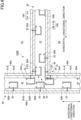
- FIG. 2 is a cross-sectional diagram of an example of the crossing structure of the building wall according to the first embodiment
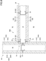
- FIG. 3 is a cross-sectional diagram of another example of the crossing structure of the building wall according to the first embodiment.
- each wall thereof may be a multi-layer structure having of three or more face members on both sides, or each wall may be a form having one (one layer) face member attached to both sides.
- a crossing structure of a building wall 100 illustrated in FIG. 2 is applied to a steel-framed building, an RC (Reinforced Concrete) building, a wooden building, or the like in addition to typical detached houses and multiple dwelling complexes, such as condominiums.
- RC Reinforced Concrete
- the upper runner, the lower runner, and the studs 20A, 20B, 50A, and 50B are, for example, lightweight steel frame members having a thickness of 0.4 mm or more, and steel runners and steel studs specified in JIS A 6517 ("building steel furrings"), or their equivalent, compliant, or compatible products, may be applied.
- the plurality of studs 20A, 20B, 50A, and 50B are built between the lower runner and the upper runner at intervals of 606 mm or less (for example, intervals of 606 mm, 455 mm) in the horizontal longitudinal direction of the wall.
- the second wall 60 has a staggered arrangement in which the plurality of second A studs 50A and the plurality of second B studs 50B that are arranged at intervals with respect to the horizontal longitudinal direction are alternately offset with respect to each other in the direction perpendicular to the horizontal longitudinal direction, the third face member 40A is attached to respective single faces of the plurality of second A studs 50A, and the fourth face member 40B is attached to respective single faces of the plurality of second B studs 50B.
- the third face member 40A is a multi-layer structure of the underlay 41A formed by a plurality of underlay face members and the overlay 42A formed by a plurality of overlay face member. In one of these, the face members are arranged horizontally.
- the hollow area 45 Inside the second wall 60 is a hollow area 45, and sound insulation and heat insulation are ensured by the hollow area 45.
- the hollow area 45 may be filled with a soundproofing material such as glass wool or rock wool.
- a crossing structure 100 is formed at the crossing 70 in which the first wall 30 and the second wall 60 intersect with each other in a T-shape in a plan view, and the first corner 71 and the second corner 72 at the two inset corners of the crossing 70 face the two rooms R1 and R2, respectively.
- a wide slit 56 extending in the longitudinal direction (vertical direction) is provided in order to prevent sound from propagating through the underlay 41A of the third face member 40A included in the second wall 60.
- a gypsum plate, a gypsum board, a calcium silicate board, a particle board, a hard board, plywood, structural plywood, and the like can be used, and among them, the gypsum plate and the gypsum board can be suitably used.
- a gypsum plate, a gypsum board, calcium silicate board, and the like can be used, and among them, the gypsum board and gypsum board can be suitably used.
- the gypsum board includes a reinforced gypsum board, an ordinary hard gypsum board, a sheathing hard gypsum board, a moisture absorptive and desorptive reinforced gypsum board, a moisture absorptive and desorptive ordinary gypsum board, a moisture absorptive and desorptive sheathing hard gypsum board, a gypsum plate with a glass fiber nonwoven fabric, a glass mat gypsum board, and the like.
- the dimensions of the short side, the long side, and the thickness thereof are 910 mm ⁇ 1,820 mm ⁇ 9.5 mm for quasi-non-combustible material or are 910 mm ⁇ 1,820 mm (2,420 mm or 2,730 mm) ⁇ 12.5 mm (15 mm, 21 mm or 25 mm) for non-combustible material or the like.
- the width of the gypsum board may be 606 mm, 1,000 mm, 1,220 mm, or the like, instead of 910 mm.
- the first wall 30 is a partition wall serves as a partition between rooms R1 and R2.
- the second wall 60 may be an additional partition wall that forms the rooms R1 and R2 together with the first wall 30, or may be an outer wall.
- the sound insulation performance of the partition wall 30 can be improved by having a configuration in which no face member is attached to both sides of the first A stud 20A and the first B stud 20B included in the first wall 30, and by having the underlay 41A of the third face member 40A included in the second wall 60 have a slit 56 in the longitudinal direction at the crossing 70.
- the flat-shaped reinforcement plate 80 For the flat-shaped reinforcement plate 80 a single, elongated form is used and the flat-shaped reinforcement plate 80 has a vertical length corresponding to that of the second face member 10B and the second A stud 50A, is applied in a single, elongated form.
- the flat-shaped reinforcement plate 80 is fixed with a plurality of fasteners 28 at predetermined intervals in the vertical direction to both the second face member 10B and the second A stud 50A.
- multiple relatively short sheets may be used as the flat-shaped reinforcement plate 80, and in this case, the multiple flat-shaped reinforcement plates 80 are intermittently arranged and fixed to both the second face member 10B and the second A stud 50A.
- the crossing structure of the building wall 100 since the second corner 72 where the second face member 10B is not supported by the first B stud 20B is reinforced by the flat-shaped reinforcement plate 80, the crossing structure is excellent in both sound insulation and seismic resistance.
- the flat-shaped reinforcement plate 80 may be fixed to both the second A stud 50A and the first B stud 20B by the fastener 28. Further, a stopper may be attached to upper and lower runners (not illustrated) so as to limit movement of the flat-shaped reinforcement plate 80. Further, the flat-shaped reinforcement plate 80 may be sandwiched between the upper and lower runners (not illustrated) and spacers provided on the upper and lower runners. Further, by bringing the end face of the underlay face member 11B into contact with the second A stud 50A without interposing the underlay face member 41A therebetween, the fastening position of the fastener 28 for fastening the flat-shaped reinforcement plate 80 to the underlay face member 11B may be set closer to the second A stud 50A.
- a crossing structure of a building wall 100A illustrated in FIG. 3 differs from the crossing structure 100 in the following points. That is, in the first wall 30, the first A studs 20A and the first B studs 20B are both on the wall centerline L1, and the first face member 10A and the second face member 10B are alternately attached via bedding plates 21. In the second wall 60, the second A studs 50A and the second B studs 50B are both arranged on the wall centerline L2, and the third face member 40A and the fourth face member 40B are alternately attached via bedding plates 51.
- the crossing structure 100A the second corner 72, at which the second face member 10B is not supported by the first B stud 20B, is reinforced by the flat-shaped reinforcement plate 80, so that the crossing structure is excellent in both sound insulation and seismic resistance.
- FIG. 4 is a cross-sectional diagram of another example of the crossing structure of the building wall according to the second embodiment.
- the crossing structure of the building wall 100B illustrated in FIG. 4 is different from the crossing structure 100 in that an L-shaped reinforcement plate 85 (another example of the reinforcement plate) is used instead of the flat-shaped reinforcement plate 80.
- the L-shaped reinforcement plate 85 may be used with the structure of the crossing structure 100A provided with the bedding plates 21 and 51.
- the L-shaped reinforcement plate 85 a single, elongated form is used and the flat-shaped reinforcement plate 80 has a vertical length corresponding to that of the second face member 10B and the second A stud 50A.
- the L-shaped reinforcement plate 85 is fixed with a plurality of fasteners 28 at predetermined intervals in the vertical direction to both the second face member 10B and the second A stud 50A.
- multiple relatively short sheets may be used as the flat-shaped reinforcement plate 80, and in this case, the multiple L-shaped reinforcement plates 85 are intermittently arranged and fixed to both the second face member 10B and the second A stud 50A.
- the fixing positions of the L-shaped reinforcement plate 85 to the second face member 10B and the second A stud 50A by the fasteners 28 are preferably provided as close as possible to the second corner 72 side. This shortens the distance from the second corner 72, acting as a fulcrum, to each fastener 28, thereby reducing the pulling force caused by bending moments that may act on each fastener 28. From the standpoint of ensuring a good fastenability while being as close as possible to the second corner 72, the fastening positions using the fasteners 28 can be set at locations approximately 10 mm to 15 mm away from the second corner 72.
- the crossing structure of the building wall 100B since the second corner 72 where the second face member 10B is not supported by the first B stud 20B is reinforced by the L-shaped reinforcement plate 85, the crossing structure is excellent in both sound insulation and seismic resistance.
- the L-shaped reinforcement plate 85 may be fixed to both the second A stud 50A and the first B stud 20B by the fastener 28. Also, stoppers may be attached to upper and lower runners (not illustrated) so as to limit movement of the L-shaped reinforcement plate 85.
- the flat-shaped reinforcement plate 80 may be sandwiched between upper and lower runners (not illustrated) and spacers provided on the upper and lower runners. Further, by bringing the end face of the underlay face member 11B into contact with the second A stud 50A without interposing the underlay face member 41A therebetween, the fastening position of the fastener 28 for fastening the L-shaped reinforcement plate 85 to the underlay face member 11B may be set closer to the second A stud 50A.
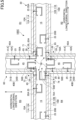
- FIG. 5 is a cross-sectional diagram of another example of the crossing structure of the building wall according to the third embodiment
- FIG. 6 is a cross-sectional diagram of a modification of the crossing structure of the building wall according to the third embodiment.
- a crossing structure of a building wall 100C illustrated in FIG. 5 is a crossing structure having a crossing 70A in which the first wall 30 and the second wall 60 intersect in a cross-shape in a plan view.
- the cross-shape of the crossing 70A has four corners including a third corner 73 and a fourth corner 74 in addition to the first corner 71 and the second corner 72.
- the crossing 70A is provided with four wide slits 56 that extend in the longitudinal direction (vertical direction).
- the first wall 30 and the second wall 60 are both partition walls, and the crossing structure is centered on the crossing 70A.
- the crossing structure 100C around the crossing structure 100C, four rooms R1, R2, R3, and R4 are provided by the first wall 30 and the second wall 60.
- the first A stud 20A to which the first face member 10A is attached is disposed at the first corner 71, and the second A stud 50A to which the third face member 40A is attached is disposed. Therefore, a structurally weak part is formed in the third face member 40A in the first corner 71.
- first B stud 20B to which second face member 10B is attached is not disposed, and second A stud 50A to which third face member 40A is attached is disposed. Consequently, a structurally weak part is formed in second face member 10B in second corner 72.
- third corner 73 second B stud 50B to which fourth face member 40B is attached is arranged, and first A stud 20A to which first face member 10A is attached is not arranged. Consequently, a structural weakness is formed in first face member 10A in third corner 73.
- fourth corner 74 first B stud 20B to which second face member 10B is attached is arranged, and second B stud 50B to which fourth face member 40B is attached is not arranged. Consequently, a structurally weak part is formed in fourth face member 40B in fourth corner 74.
- the L-shaped reinforcement plate 85 reinforces the points at the four corners 71 to 74 where the studs do not support the face members, resulting in a crossing structure excellent in both sound insulation and seismic resistance.
- a crossing structure of a building wall 100D illustrated in FIG. 6 is a form in which the flat-shaped reinforcement plate 80 is applied in the same manner as in the crossing structures 100 and 100A, in place of the L-shaped reinforcement plate 85, in the crossing structure provided with the cross-shaped crossing 70A in a plan view.
- the flat-shaped reinforcement plate 80 reinforces the points at 4 corners 71 to 74 where the studs do not support the face members, resulting in a crossing structure excellent in both sound insulation and seismic resistance.
- the crossing structure 90 illustrated in FIG. 1 that is a conventional crossing structure is Comparative Example 1
- the crossing structure 90A illustrated in FIG. 7 is Comparative Example 2
- a crossing structure 90B illustrated in FIG. 8 is Comparative Example 3.
- the crossing structure 100 illustrated in FIG. 2 is Example 1
- the crossing structure 100A illustrated in FIG. 3 is Example 2
- the crossing structure 100B illustrated in FIG. 4 is Example 3.
- the first face member 10A and the second face member 10B are fixed to both sides of a common stud 20C in the crossing 70. Therefore, in the crossing structure 90A, a structurally weak part is not formed in the crossing 70. On the other hand, although longitudinal slit 55 exists, the stud 20C can cause a sound bridge to form between the rooms R1 and R2.
Landscapes
- Engineering & Computer Science (AREA)
- Architecture (AREA)
- Physics & Mathematics (AREA)
- Electromagnetism (AREA)
- Civil Engineering (AREA)
- Structural Engineering (AREA)
- Building Environments (AREA)
- Buildings Adapted To Withstand Abnormal External Influences (AREA)
Applications Claiming Priority (2)
| Application Number | Priority Date | Filing Date | Title |
|---|---|---|---|
| JP2022138307 | 2022-08-31 | ||
| PCT/JP2023/016807 WO2024047941A1 (ja) | 2022-08-31 | 2023-04-28 | 建物壁の交差部構造 |
Publications (1)
| Publication Number | Publication Date |
|---|---|
| EP4582643A1 true EP4582643A1 (en) | 2025-07-09 |
Family
ID=90099133
Family Applications (1)
| Application Number | Title | Priority Date | Filing Date |
|---|---|---|---|
| EP23859712.4A Pending EP4582643A1 (en) | 2022-08-31 | 2023-04-28 | Intersection-portion structure of building wall |
Country Status (9)
| Country | Link |
|---|---|
| EP (1) | EP4582643A1 (https=) |
| JP (1) | JP7817769B2 (https=) |
| KR (1) | KR20250036248A (https=) |
| CN (1) | CN119744319A (https=) |
| AU (1) | AU2023332103B2 (https=) |
| CA (1) | CA3259219A1 (https=) |
| MX (1) | MX2025001460A (https=) |
| TW (1) | TW202426737A (https=) |
| WO (1) | WO2024047941A1 (https=) |
Family Cites Families (11)
| Publication number | Priority date | Publication date | Assignee | Title |
|---|---|---|---|---|
| JPS62146807U (https=) * | 1986-03-11 | 1987-09-17 | ||
| FR2622617A1 (fr) * | 1987-10-30 | 1989-05-05 | Maurice Lombardo | Panneau prefabrique a ossature bois pour mur de maison |
| JPH0547123U (ja) | 1990-12-27 | 1993-06-22 | 戸田建設株式会社 | 遮音性の間仕切壁 |
| JPH0547123A (ja) | 1991-08-16 | 1993-02-26 | Matsushita Electric Ind Co Ltd | トラツクゼロ調整装置 |
| JP3490311B2 (ja) * | 1998-11-17 | 2004-01-26 | 株式会社奥村組 | 間仕切構造 |
| JP4680418B2 (ja) * | 2001-05-25 | 2011-05-11 | 大和ハウス工業株式会社 | 遮音壁構造 |
| KR20110113881A (ko) * | 2010-04-12 | 2011-10-19 | (주)엘지하우시스 | 흡차음 성능이 개선된 조립식 벽체 및 그 조립식 구조물 |
| JP5663119B2 (ja) * | 2010-06-10 | 2015-02-04 | 吉野石膏株式会社 | 間仕切壁の目透し目地構造及びその施工方法 |
| TWI791780B (zh) * | 2018-03-04 | 2023-02-11 | 日商吉野石膏股份有限公司 | 隔間壁構造及其施工方法 |
| JP7372519B2 (ja) * | 2019-07-18 | 2023-11-01 | 株式会社イトーキ | 間仕切り構造 |
| JP7440170B2 (ja) | 2021-03-10 | 2024-02-28 | Necプラットフォームズ株式会社 | 排他制御装置、排他制御システム、制御方法及びプログラム |
-
2023
- 2023-04-28 EP EP23859712.4A patent/EP4582643A1/en active Pending
- 2023-04-28 CN CN202380061088.5A patent/CN119744319A/zh active Pending
- 2023-04-28 KR KR1020257005181A patent/KR20250036248A/ko active Pending
- 2023-04-28 WO PCT/JP2023/016807 patent/WO2024047941A1/ja not_active Ceased
- 2023-04-28 CA CA3259219A patent/CA3259219A1/en active Pending
- 2023-04-28 JP JP2024543774A patent/JP7817769B2/ja active Active
- 2023-04-28 AU AU2023332103A patent/AU2023332103B2/en active Active
- 2023-08-28 TW TW112132270A patent/TW202426737A/zh unknown
-
2025
- 2025-02-05 MX MX2025001460A patent/MX2025001460A/es unknown
Also Published As
| Publication number | Publication date |
|---|---|
| CN119744319A (zh) | 2025-04-01 |
| KR20250036248A (ko) | 2025-03-13 |
| MX2025001460A (es) | 2025-03-07 |
| AU2023332103A1 (en) | 2025-01-02 |
| JP7817769B2 (ja) | 2026-02-19 |
| AU2023332103B2 (en) | 2025-12-11 |
| CA3259219A1 (en) | 2025-04-04 |
| WO2024047941A1 (ja) | 2024-03-07 |
| TW202426737A (zh) | 2024-07-01 |
| JPWO2024047941A1 (https=) | 2024-03-07 |
Similar Documents
| Publication | Publication Date | Title |
|---|---|---|
| JP7489955B2 (ja) | モジュール式パーティションシステム | |
| JP7769172B2 (ja) | 建物の施工方法 | |
| EP4582643A1 (en) | Intersection-portion structure of building wall | |
| JP2019019504A (ja) | フラットスラブ構造 | |
| JP2025119838A (ja) | 木造家屋の耐力壁構造、耐力壁施工方法及び耐力壁パネル | |
| CN115162814A (zh) | 框架波纹钢板剪力墙建筑 | |
| JP5912465B2 (ja) | 建物及び建物の製造方法 | |
| CN218933588U (zh) | 一种防火的双层墙板 | |
| JP2999102B2 (ja) | 耐火構造の建物ユニット | |
| JP3145223B2 (ja) | ユニット式建物 | |
| CN116791815B (zh) | 一种贯通式的组合龙骨及装配式墙体 | |
| JP7777415B2 (ja) | 耐火建築物 | |
| JP7732757B2 (ja) | 耐火建築物 | |
| JP7401377B2 (ja) | 木造建物の床パネル | |
| HK40118267A (zh) | 建筑物墙壁的交叉部结构 | |
| JPH094088A (ja) | 建物用壁パネル | |
| JP2025134367A (ja) | 壁パネル | |
| JP2022114959A (ja) | 間仕切壁の遮音構造及び間仕切壁の施工方法 | |
| CN115341683A (zh) | 一种混凝土预制剪力墙夹芯保温墙板 | |
| CN115992560A (zh) | 一种基于双排c型钢龙骨的装配式复合墙 | |
| JPH10169246A (ja) | 集合住宅の構造 | |
| JPS60238546A (ja) | 壁式工法によるユニツト建造物 | |
| JPH0790940A (ja) | ユニット式建物の界壁構造 | |
| WO2003006761A1 (en) | Building panel | |
| JPS6187048A (ja) | 建築構造物 |
Legal Events
| Date | Code | Title | Description |
|---|---|---|---|
| STAA | Information on the status of an ep patent application or granted ep patent |
Free format text: STATUS: THE INTERNATIONAL PUBLICATION HAS BEEN MADE |
|
| PUAI | Public reference made under article 153(3) epc to a published international application that has entered the european phase |
Free format text: ORIGINAL CODE: 0009012 |
|
| STAA | Information on the status of an ep patent application or granted ep patent |
Free format text: STATUS: REQUEST FOR EXAMINATION WAS MADE |
|
| 17P | Request for examination filed |
Effective date: 20241230 |
|
| AK | Designated contracting states |
Kind code of ref document: A1 Designated state(s): AL AT BE BG CH CY CZ DE DK EE ES FI FR GB GR HR HU IE IS IT LI LT LU LV MC ME MK MT NL NO PL PT RO RS SE SI SK SM TR |
|
| DAV | Request for validation of the european patent (deleted) | ||
| DAX | Request for extension of the european patent (deleted) |