WO2024034163A1 - 電流センサおよび電流制御システム - Google Patents
電流センサおよび電流制御システム Download PDFInfo
- Publication number
- WO2024034163A1 WO2024034163A1 PCT/JP2023/006393 JP2023006393W WO2024034163A1 WO 2024034163 A1 WO2024034163 A1 WO 2024034163A1 JP 2023006393 W JP2023006393 W JP 2023006393W WO 2024034163 A1 WO2024034163 A1 WO 2024034163A1
- Authority
- WO
- WIPO (PCT)
- Prior art keywords
- bus bar
- current sensor
- unit
- current
- magnetic detection
- Prior art date
- Legal status (The legal status is an assumption and is not a legal conclusion. Google has not performed a legal analysis and makes no representation as to the accuracy of the status listed.)
- Ceased
Links
Images






Classifications
-
- G—PHYSICS
- G01—MEASURING; TESTING
- G01R—MEASURING ELECTRIC VARIABLES; MEASURING MAGNETIC VARIABLES
- G01R15/00—Details of measuring arrangements of the types provided for in groups G01R17/00 - G01R29/00, G01R33/00 - G01R33/26 or G01R35/00
- G01R15/14—Adaptations providing voltage or current isolation, e.g. for high-voltage or high-current networks
- G01R15/20—Adaptations providing voltage or current isolation, e.g. for high-voltage or high-current networks using galvano-magnetic devices, e.g. Hall-effect devices, i.e. measuring a magnetic field via the interaction between a current and a magnetic field, e.g. magneto resistive or Hall effect devices
- G01R15/207—Constructional details independent of the type of device used
-
- G—PHYSICS
- G01—MEASURING; TESTING
- G01R—MEASURING ELECTRIC VARIABLES; MEASURING MAGNETIC VARIABLES
- G01R1/00—Details of instruments or arrangements of the types included in groups G01R5/00 - G01R13/00 and G01R31/00
- G01R1/02—General constructional details
- G01R1/18—Screening arrangements against electric or magnetic fields, e.g. against earth's field
-
- G—PHYSICS
- G01—MEASURING; TESTING
- G01R—MEASURING ELECTRIC VARIABLES; MEASURING MAGNETIC VARIABLES
- G01R15/00—Details of measuring arrangements of the types provided for in groups G01R17/00 - G01R29/00, G01R33/00 - G01R33/26 or G01R35/00
- G01R15/14—Adaptations providing voltage or current isolation, e.g. for high-voltage or high-current networks
- G01R15/20—Adaptations providing voltage or current isolation, e.g. for high-voltage or high-current networks using galvano-magnetic devices, e.g. Hall-effect devices, i.e. measuring a magnetic field via the interaction between a current and a magnetic field, e.g. magneto resistive or Hall effect devices
-
- G—PHYSICS
- G01—MEASURING; TESTING
- G01R—MEASURING ELECTRIC VARIABLES; MEASURING MAGNETIC VARIABLES
- G01R15/00—Details of measuring arrangements of the types provided for in groups G01R17/00 - G01R29/00, G01R33/00 - G01R33/26 or G01R35/00
- G01R15/14—Adaptations providing voltage or current isolation, e.g. for high-voltage or high-current networks
- G01R15/20—Adaptations providing voltage or current isolation, e.g. for high-voltage or high-current networks using galvano-magnetic devices, e.g. Hall-effect devices, i.e. measuring a magnetic field via the interaction between a current and a magnetic field, e.g. magneto resistive or Hall effect devices
- G01R15/205—Adaptations providing voltage or current isolation, e.g. for high-voltage or high-current networks using galvano-magnetic devices, e.g. Hall-effect devices, i.e. measuring a magnetic field via the interaction between a current and a magnetic field, e.g. magneto resistive or Hall effect devices using magneto-resistance devices, e.g. field plates
-
- G—PHYSICS
- G01—MEASURING; TESTING
- G01R—MEASURING ELECTRIC VARIABLES; MEASURING MAGNETIC VARIABLES
- G01R31/00—Arrangements for testing electric properties; Arrangements for locating electric faults; Arrangements for electrical testing characterised by what is being tested not provided for elsewhere
- G01R31/34—Testing dynamo-electric machines
-
- G—PHYSICS
- G01—MEASURING; TESTING
- G01R—MEASURING ELECTRIC VARIABLES; MEASURING MAGNETIC VARIABLES
- G01R31/00—Arrangements for testing electric properties; Arrangements for locating electric faults; Arrangements for electrical testing characterised by what is being tested not provided for elsewhere
- G01R31/40—Testing power supplies
-
- G—PHYSICS
- G01—MEASURING; TESTING
- G01R—MEASURING ELECTRIC VARIABLES; MEASURING MAGNETIC VARIABLES
- G01R33/00—Arrangements or instruments for measuring magnetic variables
- G01R33/02—Measuring direction or magnitude of magnetic fields or magnetic flux
-
- H—ELECTRICITY
- H05—ELECTRIC TECHNIQUES NOT OTHERWISE PROVIDED FOR
- H05K—PRINTED CIRCUITS; CASINGS OR CONSTRUCTIONAL DETAILS OF ELECTRIC APPARATUS; MANUFACTURE OF ASSEMBLAGES OF ELECTRICAL COMPONENTS
- H05K7/00—Constructional details common to different types of electric apparatus
- H05K7/20—Modifications to facilitate cooling, ventilating, or heating
- H05K7/2089—Modifications to facilitate cooling, ventilating, or heating for power electronics, e.g. for inverters for controlling motor
- H05K7/20909—Forced ventilation, e.g. on heat dissipaters coupled to components
Definitions
- the present invention relates to a current sensor that detects a magnetic field generated by a current to be measured flowing through a bus bar and measures the current value of the current to be measured from the detected magnetic field.
- the bus bar which is the current path for the current to be measured, generates heat in an amount proportional to the square of the magnitude of the current. For this reason, as the continuously applied current to be measured increases, the amount of heat generated from the bus bar increases, causing the problem that electronic components such as magnetic sensing parts placed near the bus bar become hot. be.
- the current sensor described in Patent Document 1 includes a board having electronic components within a storage space closed by a case member, it is difficult to release heat generated from the bus bar to the outside of the storage space. Therefore, the amount of heat generated by the bus bar increases, and the temperature in the storage space becomes high enough to exceed the heat resistance temperature of the magnetic detection section, which may cause problems such as a decrease in measurement accuracy of the current sensor and a shortened product life. Therefore, in order to prevent the temperature around electronic components such as the magnetic detection unit from increasing, the present invention has been developed to be able to discharge air warmed by the heat of the bus bar to the outside of the storage space, and to measure large currents. The purpose is to provide a suitable current sensor.
- the present invention has the following configuration as a means for solving the above-mentioned problems.
- a bus bar through which a current to be measured flows, a magnetic detection section capable of detecting a magnetic field generated when the current to be measured flows through the bus bar, and a storage space for storing the magnetic detection section, and a part of the bus bar is integrated.
- a current sensor capable of measuring the current value of the current to be measured from the magnetic field detected by the magnetic detection unit, wherein the bus bar is connected to an external first housing having a cooling device at one end. unit, and the other end is connected to an external second unit having a higher temperature than the first unit, and the housing penetrates from the inside to the outside of the storage space on the side facing the first unit.
- a current sensor characterized by having a first vent hole.
- the bus bar By providing the first vent in the area of the casing that faces the first unit, when the bus bar generates heat, air flow is formed due to the temperature difference between the bus bar and the first unit, and the bus bar generates heat.
- the warmed air inside the housing can be exhausted to the outside of the storage space, thereby suppressing the temperature rise inside the housing.
- the casing may have a second vent that penetrates from the inside to the outside of the storage space on the side facing the second unit. Since the temperature of the second unit is higher than that of the first unit, air flow occurs between the first unit and the second unit. Therefore, by providing a second vent facing the second unit in addition to the first vent facing the first unit, the air flowing between the first unit and the second unit can be It becomes easier to pass through the storage space. Therefore, by using the airflow caused by the temperature difference between the first unit and the second unit, the air inside the storage space that has been warmed by the heat of the bus bar can be discharged (exhaust heat) to the outside of the storage space. .
- the magnetic detection section may be arranged between the first vent hole and the second vent hole.
- the air around the magnetic detection unit heated by the heat of the bus bar can be efficiently discharged outside the housing by using the air flow between the first vent and the second vent. Can be done. Therefore, it is possible to suppress a rise in temperature of the magnetic sensing section, and prevent deterioration of measurement accuracy of the magnetic sensing section.
- the magnetic detection section may be arranged at a position facing the bus bar.
- the magnetic sensing section is viewed so as to face the bus bar, that is, when viewed along the perpendicular direction of the plate surface of the bus bar facing the magnetic sensing section, at least a portion of the magnetic sensing section may be arranged to overlap the bus bar. Thereby, the magnetic field of the bus bar can be efficiently detected by the magnetic detection section.
- the current sensor includes a flat shield member capable of suppressing disturbance noise applied to the magnetic detection section, and the shield member is located on a side opposite to the side where the bus bar is arranged with respect to the magnetic detection section. and a second shield member that is paired with the first shield member and is located on the side opposite to the side where the magnetic detection section is arranged with respect to the bus bar as a reference. It may also have the following. Since the shield member can suppress disturbance noise applied to the magnetic detection section, the detection accuracy of the current sensor is improved.
- the current sensor includes a shield member capable of suppressing disturbance noise applied to the magnetic detection section, and the shield member has a cross-sectional shape when cut along a plane perpendicular to the direction in which the bus bar is extended. It has a U-shape, and when viewed along the direction in which the bus bar extends, the bus bar and the magnetic sensing section are arranged on both sides of the bus bar in a direction perpendicular to the direction in which the bus bar and the magnetic sensing section overlap, and on the bus bar and the magnetic sensing section.
- the magnetic sensor may be arranged so as to surround a side of the bus bar opposite to the side on which the magnetic sensing part is arranged in the direction in which the magnetic sensing part overlaps with the magnetic sensing part.
- the current sensor may include an electronic component different from the magnetic detection section, and the electronic component may be disposed within the storage space. With this configuration, it is possible to suppress the influence of heat generated by the bus bar on electronic components in addition to the magnetic detection section.
- a current control system comprising the current sensor of the present invention, the first unit, and the second unit.
- the first unit may be an inverter including the cooling device, and the second unit may be a motor.
- the air inside the storage space that has been warmed by the heat of the bus bar can be discharged outside the storage space by utilizing the air flow caused by the temperature difference in the vicinity of the current sensor. Therefore, it is possible to suppress an increase in the temperature of the magnetic detection section due to heat generation of the bus bar, and to provide a current sensor with good measurement accuracy.
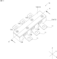
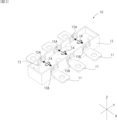
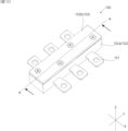
- FIG. 1 is a perspective view of a current sensor according to an embodiment of the present invention. It is a perspective view showing a state where a cover member and a board are removed from a current sensor concerning an embodiment of the present invention.
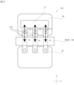
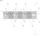
- FIG. 2 is a cross-sectional view of the current sensor of FIG. 1; 2 is a block diagram of a current control system including the current sensor of FIG. 1.
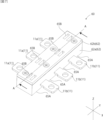
- FIG. 7 is a perspective view showing a state in which a cover member and a substrate are removed from a current sensor according to another modification.
- FIG. 7 is a perspective view of a current sensor according to another modification.
- 8 is a cross-sectional view of the current sensor of FIG. 7.
- FIG. 7 is a perspective view of a current sensor according to another modification.
- FIG. 7 is a cross-sectional view of a current sensor according to another modification.
- FIG. 7 is a cross-sectional view of a current sensor according to another modification.
- FIG. 2 is a perspective view of a conventional current sensor.
- 13 is a cross-sectional view of the current sensor of FIG. 12.
- FIG. 12 is a perspective view of a conventional current sensor 100
- FIG. 13 is a cross-sectional view of the current sensor 100 of FIG. 12 taken along the line AA along the YZ plane.
- the conventional current sensor 100 has three magnetic fields in a storage space 103 in a housing 102 formed by a case member 102a and a cover member 102b, in which a part of a bus bar 101 is integrally formed.
- a substrate 109 having a detection unit 104 is arranged.
- the storage space 103 is surrounded by the casing 102, and since there is usually no gap large enough for air convection to occur, the heat generated in the bus bar 101 is trapped inside. Therefore, when the current to be measured that is continuously applied to the bus bar 101 becomes large, the temperature inside the storage space 103 increases due to the heat generated by the bus bar 101, and exceeds the heat resistance temperature of the magnetic detection section 104, causing the current sensor 100 to detect the current. Accuracy may decrease.
- one end of the bus bar 101 is connected to the inverter and the other end is connected to the motor.
- the inverter is equipped with a cooling device that cools the insulated gate bipolar transistor (IGBT). Therefore, when the current to be measured flows through the bus bar 101, for example, the temperature of the motor is about 170° C. to 180° C., and the temperature of the inverter is 100° C. or less, so that the temperature of the inverter is relatively lower than the temperature of the motor. Therefore, an air flow (convection) is formed near the current sensor 100 due to the temperature difference between the motor and the inverter.
- IGBT insulated gate bipolar transistor
- the present invention makes use of the air flow caused by the temperature difference around the current sensor to discharge the air inside the storage space 103 heated by the heat of the bus bar to the outside of the storage space 103, so that the magnetic sensing part 104 is heated to a high temperature. This prevents the detection accuracy of the current sensor 100 from deteriorating.
- FIG. 1 is a perspective view of a current sensor 10 according to an embodiment of the present invention
- FIG. 2 is a perspective view showing the current sensor 10 with the cover member 12b and the substrate 19 (see FIG. 3) removed.
- FIG. 3 is a cross-sectional view of the current sensor 10 of FIG. 1 taken along the line AA along the YZ plane.
- the current sensor 10 includes three bus bars 11 arranged side by side along the Y-axis direction, a case member 12a, and a cover member 12b.
- a storage space 13 is provided inside.
- the storage space 13 is provided with a magnetic detection section 14 capable of detecting a magnetic field generated when a current to be measured flows through the bus bar 11 .
- the bus bar 11 is a conductive material formed in a plate shape extending in a band shape along the width direction (X-axis direction) of the housing 12, and a part thereof is formed integrally with the case member 12a by insert molding or the like. .
- the bus bar 11 is through which a current to be detected and measured flows, and is made of, for example, copper, brass, aluminum, or the like.
- the bus bar 11 is provided so that two opposing plate surfaces correspond to the upper and lower sides of the housing 12 (both sides in the Z-axis direction), respectively.
- Both end portions of the bus bar 11 in the X-axis direction which are connection portions with the outside, do not necessarily have a shape that is line symmetrical with respect to the Y-axis.
- the bus bar 11 does not need to have a flat plate shape in a portion other than the portion facing the magnetic sensing portion 14, and may be subjected to a bending process, for example.
- the magnetic detection unit 14 detects the magnetic field (induced magnetic field) generated when the current to be measured flows through the bus bar 11, and measures the current value of the current to be measured.
- a magnetoresistive element such as a GMR (giant magnetoresistive) element or a TMR (tunnel magnetic effect) element, which utilizes a magnetoresistive effect in which electrical resistance changes depending on an external magnetic field, is used.
- the board 19 has a plate surface parallel to the XY plane, and the magnetic detection units 14 are arranged at positions facing each bus bar 11 on the board surface of the board 19 arranged in the storage space 13. At least a portion of the sensor section in the magnetic detection section 14 faces the corresponding bus bar 11 and overlaps the opposing bus bar 11 when viewed along the Z-axis. It is preferable that the three magnetic sensing sections 14 are provided on the same side of the substrate 19.
- the current sensor 10 includes a flat shield member including a first shield member 16A and a second shield member 16B for each of three sets of bus bars 11 and magnetic sensing portion 14. 16 are provided.
- the first shield member 16A and the second shield member 16B are, for example, configured by stacking a plurality of metal plate-like bodies having the same shape. Note that the shield member 16 may be configured to include only one of the first shield member 16A and the second shield member 16B.
- the first shield member 16A is formed integrally with the cover member 12b, and is arranged on the side opposite to the side where the bus bar 11 is arranged with respect to the magnetic detection section 14.
- the second shield member 16B is formed integrally with the case member 12a, and is arranged on the side opposite to the side on which the magnetic detection section 14 is arranged with the bus bar 11 as a reference.
- the first shield member 16A and the second shield member 16B suppress the influence of disturbance noise applied to the magnetic detection section 14, thereby improving the detection accuracy of the current sensor 10.
- FIG. 4 is a block diagram of a current control system 110 including the current sensor 10 of FIG.
- the present invention can be implemented as a current control system 110 that includes a current sensor 10, a first unit 20, and a second unit 30 whose temperature is higher than that of the first unit.
- the first unit 20 is an inverter equipped with a cooling device 21, and the second unit 30 is a motor.
- the temperature of the motor is 170 to 180° C.
- the temperature of the inverter is 100° C. or less, so air moves near the current sensor 10 due to the temperature difference.
- One end 11a of the bus bar 11 of the current sensor 10 is connected to an external first unit 20 equipped with a cooling device 21, and the other end 11b is connected to a second unit 30. Since the temperature of the second unit 30 is higher than that of the first unit 20, an air flow (convection) is formed due to the temperature difference in the direction (X-axis direction) indicated by double-sided arrows in FIG. .
- the housing 12 has a first ventilation hole 15A that penetrates from the inside to the outside of the storage space 13 on the side facing the first unit 20. Further, on the side facing the second unit 30, a second ventilation hole 15B is provided that penetrates from the inside to the outside of the storage space 13. A part of the air flow along the X-axis direction due to the temperature difference passes through the storage space 13 of the housing 12 through the first vent hole 15A and the second vent hole 15B. Therefore, even if the air in the storage space 13 becomes high temperature due to the heat generated by the bus bar 11, the high temperature air can be discharged outside the storage space 13 by using the air flow caused by the temperature difference. The detection accuracy of the current sensor 10 can be maintained by preventing the detection unit 14 from becoming high temperature.
- the magnetic detection section 14 In order to prevent high-temperature air from remaining in the storage space 13 by taking in air from outside the storage space 13 into the vicinity of the magnetic detection unit 14, there is a gap between the first ventilation port 15A and the second ventilation port 15B. It is preferable to arrange the magnetic detection section 14 at. With this configuration, when a large current is continuously applied as the current to be measured, the heat generated by the bus bar 11 can be suppressed from affecting the magnetic detection section 14, and the measurement accuracy of the current sensor 10 can be maintained at a high level. .
- the magnetic detection unit 14 is arranged between the first vent 15A and the second vent 15B on the line segment connecting the first vent 15A and the second vent 15B. This means that at least a portion of the magnetic detection section 14 is located.
- a line segment connecting the first vent port 15A and the second vent port 15B is a line segment whose points on both sides are located in arbitrary areas of the first vent port 15A and the second vent port 15B, respectively. means.
- both the first vent hole 15A and the second vent hole 15B have a grid shape in which three elongated rectangular holes are formed with the Z-axis direction as the longitudinal direction.
- the inside of the storage space 13 is cooled by utilizing the air flow caused by the temperature difference. , foreign matter can be prevented from entering the storage space 13.
- first vent holes 15A and three second vent holes 15B are provided, which is the same as the number of bus bars 11 and magnetic sensing sections 14.
- the number of the first vent holes 15A and the second vent holes 15B is not limited to three, and may be different from the bus bar 11 and the magnetic sensing section 14.
- FIG. 5 is a block diagram of a current control system 120 including a current sensor 40 according to a modification.
- the casing 12 of the current sensor 10 described above includes a first vent 15A and a second vent 15B. 20 and the second unit 30, the air flow caused by the temperature difference is utilized.
- the current sensor 40 includes only the first vent 15A that faces the first unit 20, which has a relatively lower temperature, of the first unit 20 and the second unit 30 to which the bus bar 11 is connected. It is different from the current sensor 10 in this point.
- the heat generated by the bus bar 11 inside the casing 42 causes the inside of the storage space 13 to
- a temperature difference occurs between the bus bar 11 and the first unit 20. Therefore, air flows due to the temperature difference in the direction of the arrows on both sides of the X-axis shown in FIG. 5 . Therefore, like the current sensor 10, by utilizing the air flow caused by the temperature difference between the first unit 20 and the bus bar 11, the air heated by the heat in the storage space 43 is discharged to the outside, and the magnetic detection unit 14 It is possible to suppress the measurement accuracy of the current sensor 40 from decreasing due to the temperature becoming high.
- FIG. 6 is a perspective view of a current sensor 50 according to a modification.
- the figure shows a state in which the cover member 12b and the substrate 19 are removed, but the current sensor 50, like the current sensor 10, includes the cover member 12b, and the magnetic detection section 14 is attached to the substrate 19. It is set in.
- the current sensor 50 differs from the current sensor 10 in that it includes a bus bar 51 having a different shape from the bus bar 11, and a second vent 55B is provided at a position corresponding to the shape of the bus bar 51.
- the configuration of the current sensor 40 other than these is the same as the current sensor 10.
- the bus bar 51 is bent.
- the second ventilation hole 55B should be formed at a position that overlaps with the first ventilation hole 15A when viewed along the X-axis direction and overlaps with the bus bar 51 when viewed along the Z-axis direction. I can't. Therefore, in the current sensor 50, a first vent hole 15A is formed at a position overlapping each bus bar 51 when viewed along the Z-axis direction, and second vent holes are formed on both sides of each bus bar 51 in the Y-axis direction. 55B. Thereby, an air flow is formed in the storage space 53 in an oblique direction with respect to the width direction (X-axis direction) of the case member 52a (casing 52).
- the first ventilation holes 15A and the second vent hole 55B are configured in this way, similar to the current sensor 50, air flows from inside the storage space 53 to outside the storage space 53 by utilizing the air flow due to the difference in external temperature. By discharging the high-temperature air, it is possible to suppress a decrease in measurement accuracy of the current sensor 50 due to the magnetic detection unit 14 becoming hot.
- the first ventilation holes 15A may be formed on both sides of each bus bar 51 in the Y-axis direction.
- FIG. 7 is a perspective view of a current sensor 60 according to another modification
- FIG. 8 is a cross-sectional view of the current sensor 60 taken along the line AA in FIG. 7 along the YZ plane.
- the current sensor 60 differs from the current sensor 10 in the positions in the housing 62 where the first vent hole 65A and the second vent hole 65B are provided.
- the configuration of the current sensor 60 other than this is the same as that of the current sensor 10.
- the first unit 20 to which one end 11a of the bus bar 11 is connected and the second unit 30 to which the other end 11b is connected are arranged at various positions depending on the design of the product. Therefore, the positions where the first unit 20 and the second unit 30 are arranged are not limited to the X-axis direction of the current sensor 10 shown in FIG. 4.
- a first unit 20 including a cooling device 21 is arranged on the case member 62a side in the Z-axis direction
- a second unit 30 is arranged on the case member 62a side in the Z-axis direction.
- a first vent hole 65A is provided on the bottom surface of the case member 62a (the surface where the perpendicular line is parallel to the Z-axis)
- a first vent hole 65A is provided on the top surface of the cover member 62b (the surface where the perpendicular line is parallel to the Z-axis).
- a second vent hole 65B is provided on the parallel surface.
- the air warmed by the heat generated in the bus bar 11 is discharged to the outside of the storage space 63 by utilizing the air flow in the Z-axis direction shown by the arrows on both sides in FIG. It can suppress high temperatures.
- a hole may be provided in a part of the substrate 19 that penetrates the substrate 19 in the Z-axis direction.
- the board 19 is provided within the storage space 13 with a gap between it and the case member 62a around its periphery. Therefore, even without providing holes, the warmed air in the storage space 63 can be discharged to the outside by utilizing the movement of air in the Z-axis direction.
- first vent holes 65A and the second vent holes 65B may be set as appropriate depending on the first unit 20 and the second unit 30. Further, like the current sensor 40 shown in FIG. 5, the first vent hole 65A may be provided only on the surface facing the first unit.
- FIG. 9 is a perspective view of a current sensor 70 according to another modification, in which a first vent hole 75A and a second vent hole are provided on both sides of the case member 72a in the Y-axis direction perpendicular to the extending direction of the bus bar 11.
- a vent hole 75B is provided. Therefore, when the first unit 20 and the second unit 30 (see FIGS. 4 and 5) are provided on both sides in the longitudinal direction (Y-axis direction) of the casing 72 consisting of the case member 72a and the cover member 72b, By utilizing the movement of air caused by the temperature difference, the warmed air in the storage space 13 can be discharged to the outside.
- the first unit and the second unit are provided at various positions depending on the design.
- a vent is provided.
- FIG. 10 is a cross-sectional view of a current sensor 80 according to another modification, showing the structure of a portion corresponding to the portion indicated by line AA of the current sensor 10 in FIG.
- the current sensor 80 does not include a flat plate-shaped first shield member 16A, and is replaced with a flat plate-shaped second shield member 16B, which is perpendicular to the direction in which the bus bar 11 extends (X-axis direction).
- the current sensor 10 is different from the current sensor 10 in that it includes a second shield member 86B whose cross-sectional shape is U-shaped when cut along the direction, and the other configurations are the same as the current sensor 10.
- the second shield member 86B is arranged so as to surround three sides of the bus bar 11 except for the side where the magnetic detection section 14 is arranged, when viewed along the direction in which the bus bar 11 extends (X-axis direction). There is. That is, both sides of the bus bar 11 in the Y-axis direction and the opposite side of the Z-axis direction from the side on which the magnetic detection section 14 is arranged are surrounded by the second shield member 86B. Therefore, the second shield member 86B can suppress the influence from adjacent bus bars 11 other than the bus bar 11 that the magnetic detection unit 14 faces. Therefore, the influence of the external magnetic field on the magnetic detection unit 14 can be suppressed, and the detection accuracy of the current sensor 80 can be improved.
- FIG. 11 is a cross-sectional view of a current sensor 90 according to another modification.
- the current sensor 90 is different from the current sensor 10 in that an electronic component 98 different from the magnetic sensing portion 14 is arranged in the storage space 13 together with the magnetic sensing portion 14, and the other configurations are similar to the current sensor 10.
- the electronic components 98 include components constituting an IC chip, such as a capacitor and a resistor.
- the current sensor 90 has the housing 12 equipped with the first ventilation port 15A and the second ventilation port 15B. Air warmed by heat generation can be discharged to the outside of the storage space 13. Therefore, it is possible to prevent the magnetic detection unit 14 and the electronic component 98 from becoming hot in the storage space 13 due to the heat generated by the bus bar 11, thereby preventing the detection accuracy of the current sensor 90 from decreasing.
- the present invention suppresses the temperature rise of the magnetic detection unit by discharging air warmed by the heat generated by the large current flowing through the bus bar to the outside of the storage space, thereby suppressing the decrease in measurement accuracy of the current sensor. It is useful as a current sensor that measures the current between a motor and an inverter.
Landscapes
- Physics & Mathematics (AREA)
- General Physics & Mathematics (AREA)
- Engineering & Computer Science (AREA)
- Microelectronics & Electronic Packaging (AREA)
- Thermal Sciences (AREA)
- Condensed Matter Physics & Semiconductors (AREA)
- Measuring Instrument Details And Bridges, And Automatic Balancing Devices (AREA)
Priority Applications (5)
| Application Number | Priority Date | Filing Date | Title |
|---|---|---|---|
| DE112023003399.4T DE112023003399T5 (de) | 2022-08-08 | 2023-02-22 | Stromsensor und stromsteuersystem |
| KR1020257004095A KR102865924B1 (ko) | 2022-08-08 | 2023-02-22 | 전류 센서 및 전류 제어 시스템 |
| JP2024540245A JP7709619B2 (ja) | 2022-08-08 | 2023-02-22 | 電流センサおよび電流制御システム |
| CN202380054252.XA CN119585626A (zh) | 2022-08-08 | 2023-02-22 | 电流传感器以及电流控制系统 |
| US19/013,020 US20250147076A1 (en) | 2022-08-08 | 2025-01-08 | Current Sensor And Current Control System |
Applications Claiming Priority (2)
| Application Number | Priority Date | Filing Date | Title |
|---|---|---|---|
| JP2022126454 | 2022-08-08 | ||
| JP2022-126454 | 2022-08-08 |
Related Child Applications (1)
| Application Number | Title | Priority Date | Filing Date |
|---|---|---|---|
| US19/013,020 Continuation US20250147076A1 (en) | 2022-08-08 | 2025-01-08 | Current Sensor And Current Control System |
Publications (1)
| Publication Number | Publication Date |
|---|---|
| WO2024034163A1 true WO2024034163A1 (ja) | 2024-02-15 |
Family
ID=89851307
Family Applications (1)
| Application Number | Title | Priority Date | Filing Date |
|---|---|---|---|
| PCT/JP2023/006393 Ceased WO2024034163A1 (ja) | 2022-08-08 | 2023-02-22 | 電流センサおよび電流制御システム |
Country Status (6)
| Country | Link |
|---|---|
| US (1) | US20250147076A1 (https=) |
| JP (1) | JP7709619B2 (https=) |
| KR (1) | KR102865924B1 (https=) |
| CN (1) | CN119585626A (https=) |
| DE (1) | DE112023003399T5 (https=) |
| WO (1) | WO2024034163A1 (https=) |
Families Citing this family (1)
| Publication number | Priority date | Publication date | Assignee | Title |
|---|---|---|---|---|
| US12474414B2 (en) * | 2024-01-04 | 2025-11-18 | Allegro Microsystems, Llc | System and method to monitor power source connections |
Citations (9)
| Publication number | Priority date | Publication date | Assignee | Title |
|---|---|---|---|---|
| JP2012242176A (ja) * | 2011-05-17 | 2012-12-10 | Tdk Corp | 電流センサ |
| JP2013074670A (ja) * | 2011-09-27 | 2013-04-22 | Keihin Corp | 電力変換装置 |
| JP2014085278A (ja) * | 2012-10-25 | 2014-05-12 | Sumitomo Wiring Syst Ltd | 電流センサ |
| JP2017044486A (ja) * | 2015-08-24 | 2017-03-02 | アイシン精機株式会社 | 電流センサ |
| JP2019207251A (ja) * | 2014-03-24 | 2019-12-05 | レム・インテレクチュアル・プロパティ・エスエイLem Intellectual Property Sa | 電流変換器 |
| JP2020115104A (ja) * | 2019-01-18 | 2020-07-30 | 株式会社デンソー | 電流センサ |
| WO2021090603A1 (ja) * | 2019-11-05 | 2021-05-14 | 株式会社デンソー | センサユニット |
| JP2021182821A (ja) * | 2020-05-19 | 2021-11-25 | 株式会社デンソー | 電力変換装置 |
| JP2021197831A (ja) * | 2020-06-15 | 2021-12-27 | 株式会社デンソー | 電気ユニット |
Family Cites Families (11)
| Publication number | Priority date | Publication date | Assignee | Title |
|---|---|---|---|---|
| KR20100137977A (ko) * | 2009-06-24 | 2010-12-31 | 오석환 | 냉각장치를 구비한 배전반 |
| JP2014106156A (ja) * | 2012-11-28 | 2014-06-09 | Nidec Sankyo Corp | 磁気センサ装置 |
| KR101413484B1 (ko) | 2013-01-30 | 2014-07-14 | 태성전장주식회사 | 차량용 비접촉식 2채널 전류센서 |
| JP6477089B2 (ja) | 2014-05-23 | 2019-03-06 | 株式会社デンソー | 電流センサ付バスバーモジュール |
| WO2016148022A1 (ja) | 2015-03-17 | 2016-09-22 | アルプス・グリーンデバイス株式会社 | 電流センサ |
| CN105007000B (zh) | 2015-06-25 | 2018-08-03 | 简式国际汽车设计(北京)有限公司 | 一种电动汽车双电机控制器 |
| CN109155592B (zh) | 2016-04-28 | 2021-01-01 | 日产自动车株式会社 | 车载用电力变换装置 |
| KR101847011B1 (ko) * | 2016-05-02 | 2018-05-04 | 주식회사 동양센서 | 전류 센서 |
| KR101871214B1 (ko) * | 2016-08-19 | 2018-06-27 | 부산대학교 산학협력단 | 실드 구조물 및 전류 센서 |
| JP7398943B2 (ja) | 2019-12-10 | 2023-12-15 | 三菱電機株式会社 | 加熱調理器 |
| JP7375652B2 (ja) | 2020-03-30 | 2023-11-08 | 株式会社アイシン | 車両用駆動装置及びバスバーモジュール |
-
2023
- 2023-02-22 WO PCT/JP2023/006393 patent/WO2024034163A1/ja not_active Ceased
- 2023-02-22 JP JP2024540245A patent/JP7709619B2/ja active Active
- 2023-02-22 KR KR1020257004095A patent/KR102865924B1/ko active Active
- 2023-02-22 DE DE112023003399.4T patent/DE112023003399T5/de active Pending
- 2023-02-22 CN CN202380054252.XA patent/CN119585626A/zh active Pending
-
2025
- 2025-01-08 US US19/013,020 patent/US20250147076A1/en active Pending
Patent Citations (9)
| Publication number | Priority date | Publication date | Assignee | Title |
|---|---|---|---|---|
| JP2012242176A (ja) * | 2011-05-17 | 2012-12-10 | Tdk Corp | 電流センサ |
| JP2013074670A (ja) * | 2011-09-27 | 2013-04-22 | Keihin Corp | 電力変換装置 |
| JP2014085278A (ja) * | 2012-10-25 | 2014-05-12 | Sumitomo Wiring Syst Ltd | 電流センサ |
| JP2019207251A (ja) * | 2014-03-24 | 2019-12-05 | レム・インテレクチュアル・プロパティ・エスエイLem Intellectual Property Sa | 電流変換器 |
| JP2017044486A (ja) * | 2015-08-24 | 2017-03-02 | アイシン精機株式会社 | 電流センサ |
| JP2020115104A (ja) * | 2019-01-18 | 2020-07-30 | 株式会社デンソー | 電流センサ |
| WO2021090603A1 (ja) * | 2019-11-05 | 2021-05-14 | 株式会社デンソー | センサユニット |
| JP2021182821A (ja) * | 2020-05-19 | 2021-11-25 | 株式会社デンソー | 電力変換装置 |
| JP2021197831A (ja) * | 2020-06-15 | 2021-12-27 | 株式会社デンソー | 電気ユニット |
Also Published As
| Publication number | Publication date |
|---|---|
| KR102865924B1 (ko) | 2025-09-30 |
| DE112023003399T5 (de) | 2025-06-05 |
| JPWO2024034163A1 (https=) | 2024-02-15 |
| JP7709619B2 (ja) | 2025-07-16 |
| KR20250034984A (ko) | 2025-03-11 |
| CN119585626A (zh) | 2025-03-07 |
| US20250147076A1 (en) | 2025-05-08 |
Similar Documents
| Publication | Publication Date | Title |
|---|---|---|
| US10267826B2 (en) | Bus bar module equipped with current sensor for measuring value of current in the bus bar | |
| CN107430156A (zh) | 电流传感器 | |
| US20250147075A1 (en) | Current Sensor | |
| US12222366B2 (en) | Current sensor assembly and inverter assembly having a plurality of sensors | |
| US11555834B2 (en) | Magnetic sensor and method of manufacturing such, magnetic control device, and current sensor design method | |
| JP7047435B2 (ja) | 電流センサの設計方法 | |
| US9335349B2 (en) | Current sensor | |
| US20250147076A1 (en) | Current Sensor And Current Control System | |
| US11333687B2 (en) | Sensor unit | |
| WO2012046547A1 (ja) | 電流センサ | |
| US11469680B2 (en) | Power converter | |
| WO2020003674A1 (ja) | 電力変換装置 | |
| US12504447B2 (en) | Current sensor | |
| JP2012063285A (ja) | 電流センサ | |
| US20180045793A1 (en) | Electrical assembly for measuring a current intensity of a direct-current circuit by means of the anisotropic magnetoresistive effect | |
| JP2017085822A (ja) | 電力変換器 | |
| JP6869476B2 (ja) | 電流センサ | |
| US20240248121A1 (en) | Current Sensor | |
| JP7579466B2 (ja) | 電流センサ | |
| WO2025258208A1 (ja) | 電流センサ、パワーモジュールおよび電流センサの製造方法 | |
| WO2024089975A1 (ja) | 電流センサ | |
| CN118176426A (zh) | 电流传感器 |
Legal Events
| Date | Code | Title | Description |
|---|---|---|---|
| 121 | Ep: the epo has been informed by wipo that ep was designated in this application |
Ref document number: 23852150 Country of ref document: EP Kind code of ref document: A1 |
|
| WWE | Wipo information: entry into national phase |
Ref document number: 2024540245 Country of ref document: JP |
|
| WWE | Wipo information: entry into national phase |
Ref document number: 202380054252.X Country of ref document: CN |
|
| ENP | Entry into the national phase |
Ref document number: 20257004095 Country of ref document: KR Kind code of ref document: A |
|
| WWE | Wipo information: entry into national phase |
Ref document number: 1020257004095 Country of ref document: KR |
|
| WWE | Wipo information: entry into national phase |
Ref document number: 202547019116 Country of ref document: IN |
|
| WWP | Wipo information: published in national office |
Ref document number: 202380054252.X Country of ref document: CN |
|
| WWE | Wipo information: entry into national phase |
Ref document number: 112023003399 Country of ref document: DE |
|
| WWP | Wipo information: published in national office |
Ref document number: 1020257004095 Country of ref document: KR |
|
| WWP | Wipo information: published in national office |
Ref document number: 202547019116 Country of ref document: IN |
|
| WWP | Wipo information: published in national office |
Ref document number: 112023003399 Country of ref document: DE |
|
| 122 | Ep: pct application non-entry in european phase |
Ref document number: 23852150 Country of ref document: EP Kind code of ref document: A1 |