WO2024024594A1 - プラズマ処理装置及び電源システム - Google Patents
プラズマ処理装置及び電源システム Download PDFInfo
- Publication number
- WO2024024594A1 WO2024024594A1 PCT/JP2023/026442 JP2023026442W WO2024024594A1 WO 2024024594 A1 WO2024024594 A1 WO 2024024594A1 JP 2023026442 W JP2023026442 W JP 2023026442W WO 2024024594 A1 WO2024024594 A1 WO 2024024594A1
- Authority
- WO
- WIPO (PCT)
- Prior art keywords
- state
- signal
- voltage level
- repetition period
- period
- Prior art date
- Legal status (The legal status is an assumption and is not a legal conclusion. Google has not performed a legal analysis and makes no representation as to the accuracy of the status listed.)
- Ceased
Links
Images








Classifications
-
- H—ELECTRICITY
- H01—ELECTRIC ELEMENTS
- H01J—ELECTRIC DISCHARGE TUBES OR DISCHARGE LAMPS
- H01J37/00—Discharge tubes with provision for introducing objects or material to be exposed to the discharge, e.g. for the purpose of examination or processing thereof
- H01J37/32—Gas-filled discharge tubes
- H01J37/32009—Arrangements for generation of plasma specially adapted for examination or treatment of objects, e.g. plasma sources
- H01J37/32082—Radio frequency generated discharge
- H01J37/32137—Radio frequency generated discharge controlling of the discharge by modulation of energy
- H01J37/32146—Amplitude modulation, includes pulsing
-
- H—ELECTRICITY
- H01—ELECTRIC ELEMENTS
- H01J—ELECTRIC DISCHARGE TUBES OR DISCHARGE LAMPS
- H01J37/00—Discharge tubes with provision for introducing objects or material to be exposed to the discharge, e.g. for the purpose of examination or processing thereof
- H01J37/32—Gas-filled discharge tubes
- H01J37/32009—Arrangements for generation of plasma specially adapted for examination or treatment of objects, e.g. plasma sources
- H01J37/32082—Radio frequency generated discharge
- H01J37/32128—Radio frequency generated discharge using particular waveforms, e.g. polarised waves
-
- H—ELECTRICITY
- H01—ELECTRIC ELEMENTS
- H01J—ELECTRIC DISCHARGE TUBES OR DISCHARGE LAMPS
- H01J37/00—Discharge tubes with provision for introducing objects or material to be exposed to the discharge, e.g. for the purpose of examination or processing thereof
- H01J37/32—Gas-filled discharge tubes
- H01J37/32009—Arrangements for generation of plasma specially adapted for examination or treatment of objects, e.g. plasma sources
- H01J37/32082—Radio frequency generated discharge
- H01J37/32137—Radio frequency generated discharge controlling of the discharge by modulation of energy
- H01J37/32155—Frequency modulation
- H01J37/32165—Plural frequencies
-
- H—ELECTRICITY
- H01—ELECTRIC ELEMENTS
- H01J—ELECTRIC DISCHARGE TUBES OR DISCHARGE LAMPS
- H01J37/00—Discharge tubes with provision for introducing objects or material to be exposed to the discharge, e.g. for the purpose of examination or processing thereof
- H01J37/32—Gas-filled discharge tubes
- H01J37/32009—Arrangements for generation of plasma specially adapted for examination or treatment of objects, e.g. plasma sources
- H01J37/32082—Radio frequency generated discharge
- H01J37/32174—Circuits specially adapted for controlling the RF discharge
-
- H—ELECTRICITY
- H01—ELECTRIC ELEMENTS
- H01J—ELECTRIC DISCHARGE TUBES OR DISCHARGE LAMPS
- H01J37/00—Discharge tubes with provision for introducing objects or material to be exposed to the discharge, e.g. for the purpose of examination or processing thereof
- H01J37/32—Gas-filled discharge tubes
- H01J37/32431—Constructional details of the reactor
- H01J37/32532—Electrodes
- H01J37/32568—Relative arrangement or disposition of electrodes; moving means
-
- H—ELECTRICITY
- H01—ELECTRIC ELEMENTS
- H01J—ELECTRIC DISCHARGE TUBES OR DISCHARGE LAMPS
- H01J37/00—Discharge tubes with provision for introducing objects or material to be exposed to the discharge, e.g. for the purpose of examination or processing thereof
- H01J37/32—Gas-filled discharge tubes
- H01J37/32431—Constructional details of the reactor
- H01J37/32715—Workpiece holder
-
- H—ELECTRICITY
- H05—ELECTRIC TECHNIQUES NOT OTHERWISE PROVIDED FOR
- H05H—PLASMA TECHNIQUE; PRODUCTION OF ACCELERATED ELECTRICALLY-CHARGED PARTICLES OR OF NEUTRONS; PRODUCTION OR ACCELERATION OF NEUTRAL MOLECULAR OR ATOMIC BEAMS
- H05H1/00—Generating plasma; Handling plasma
- H05H1/24—Generating plasma
- H05H1/46—Generating plasma using applied electromagnetic fields, e.g. high frequency or microwave energy
-
- H—ELECTRICITY
- H10—SEMICONDUCTOR DEVICES; ELECTRIC SOLID-STATE DEVICES NOT OTHERWISE PROVIDED FOR
- H10P—GENERIC PROCESSES OR APPARATUS FOR THE MANUFACTURE OR TREATMENT OF DEVICES COVERED BY CLASS H10
- H10P14/00—Formation of materials, e.g. in the shape of layers or pillars
- H10P14/20—Formation of materials, e.g. in the shape of layers or pillars of semiconductor materials
- H10P14/29—Formation of materials, e.g. in the shape of layers or pillars of semiconductor materials characterised by the substrates
-
- H—ELECTRICITY
- H10—SEMICONDUCTOR DEVICES; ELECTRIC SOLID-STATE DEVICES NOT OTHERWISE PROVIDED FOR
- H10P—GENERIC PROCESSES OR APPARATUS FOR THE MANUFACTURE OR TREATMENT OF DEVICES COVERED BY CLASS H10
- H10P50/00—Etching of wafers, substrates or parts of devices
- H10P50/20—Dry etching; Plasma etching; Reactive-ion etching
- H10P50/24—Dry etching; Plasma etching; Reactive-ion etching of semiconductor materials
- H10P50/242—Dry etching; Plasma etching; Reactive-ion etching of semiconductor materials of Group IV materials
-
- H—ELECTRICITY
- H01—ELECTRIC ELEMENTS
- H01J—ELECTRIC DISCHARGE TUBES OR DISCHARGE LAMPS
- H01J2237/00—Discharge tubes exposing object to beam, e.g. for analysis treatment, etching, imaging
- H01J2237/32—Processing objects by plasma generation
- H01J2237/33—Processing objects by plasma generation characterised by the type of processing
- H01J2237/334—Etching
-
- H—ELECTRICITY
- H01—ELECTRIC ELEMENTS
- H01J—ELECTRIC DISCHARGE TUBES OR DISCHARGE LAMPS
- H01J37/00—Discharge tubes with provision for introducing objects or material to be exposed to the discharge, e.g. for the purpose of examination or processing thereof
- H01J37/32—Gas-filled discharge tubes
- H01J37/32009—Arrangements for generation of plasma specially adapted for examination or treatment of objects, e.g. plasma sources
- H01J37/32082—Radio frequency generated discharge
- H01J37/32091—Radio frequency generated discharge the radio frequency energy being capacitively coupled to the plasma
Definitions
- the present disclosure relates to a plasma processing apparatus and a power supply system.
- U.S. Pat. No. 5,001,302 provides a plasma source with a multi-level RF power waveform having a first power level during at least a first pulse period and a second power level during a second pulse period.
- a first species of the supply gas is ionized during a first pulse period
- a second species is ionized during a second pulse period.
- the present disclosure provides a technique that can improve the controllability of etching shape.
- a plasma processing chamber a substrate support part disposed in the plasma processing chamber and including a lower electrode, an upper electrode disposed above the substrate support part, and the upper electrode or an RF power source configured to provide an RF signal to the bottom electrode, the RF signal having a first power level during a first state within a first repetition period, and wherein the RF signal has a first power level during a first state within a first repetition period; a first power level during a second state within the first repetition period, and a second power level less than the first power level during a third state within the first repetition period; an RF power source having a third power level less than the second power level during a fourth state of the invention, and a DC power source configured to apply a DC signal to the bottom electrode, wherein the DC signal is , a sequence of voltage pulses having a first voltage level during the first state within the first repetition period and a second voltage level during the second state within the first repetition period. , an absolute value of the second voltage level is greater
- the controllability of the etching shape can be improved.
- FIG. 1 is a diagram illustrating an example of a plasma processing system according to an embodiment.
- FIG. 1 is a schematic cross-sectional view showing an example of a plasma processing apparatus according to an embodiment.
- FIG. 3 is a diagram showing an example of an RF signal and a DC signal according to the first embodiment.
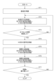
- 5 is a flowchart showing an example of an etching process according to the first embodiment.
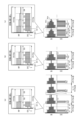
- FIG. 3 is a diagram for explaining etching processing according to the first embodiment.
- FIG. 7 is a diagram showing an example of an RF signal and a DC signal according to the second embodiment. 7 is a flowchart showing an example of an etching process according to the second embodiment.
- FIG. 1 is a diagram illustrating an example of a plasma processing system according to an embodiment.
- FIG. 1 is a schematic cross-sectional view showing an example of a plasma processing apparatus according to an embodiment.
- FIG. 7 is a diagram showing another example of an RF signal and a DC signal according to the second embodiment.
- FIG. 7 is a diagram showing another example of an RF signal and a DC signal according to the second embodiment.
- FIG. 7 is a diagram showing an example of an RF signal and a DC signal according to a modification.
- 6 is a diagram showing an example of an RF signal and a DC signal according to Modification 1.
- FIG. 7 is a diagram showing an example of an RF signal and a DC signal according to Modification 2.
- FIG. 7 is a diagram showing an example of an RF signal and a DC signal according to Modification 2-1.
- FIG. 7 is a diagram showing an example of an RF signal and a DC signal according to Modification 2-2.
- FIG. 7 is a diagram showing an example of an RF signal and a DC signal according to Modification 3.
- 7 is a diagram showing an example of an RF signal and a DC signal according to modification example 4.
- FIG. 7 is a diagram showing an example of an RF signal and a DC signal according to Modification 6.
- FIG. 1 is a diagram for explaining a configuration example of a plasma processing system.
- a plasma processing system includes a plasma processing apparatus 1 and a controller 2.
- the plasma processing system is an example of a substrate processing system
- the plasma processing apparatus 1 is an example of a substrate processing apparatus.
- the plasma processing apparatus 1 includes a plasma processing chamber 10, a substrate support section 11, and a plasma generation section 12.
- the plasma processing chamber 10 has a plasma processing space.
- the plasma processing chamber 10 also includes at least one gas supply port for supplying at least one processing gas to the plasma processing space, and at least one gas exhaust port for discharging gas from the plasma processing space.
- the gas supply port is connected to a gas supply section 20 (FIG. 2) described later, and the gas discharge port is connected to an exhaust system 40 (FIG. 2) described later.
- the substrate support section 11 is disposed within the plasma processing space and has a substrate support surface for supporting a substrate.
- the plasma generation unit 12 is configured to generate plasma from at least one processing gas supplied into the plasma processing space.
- the plasmas formed in the plasma processing space are capacitively coupled plasma (CCP), inductively coupled plasma (ICP), and ECR plasma (Electron-Cyclotron-resonance plasma).
- CCP capacitively coupled plasma
- ICP inductively coupled plasma
- ECR plasma Electro-Cyclotron-resonance plasma
- HWP Helicon wave excited plasma
- SWP surface wave plasma
- various types of plasma generation sections may be used, including an AC (Alternating Current) plasma generation section and a DC (Direct Current) plasma generation section.
- the AC signal (AC power) used in the AC plasma generator has a frequency in the range of 100 kHz to 10 GHz. Therefore, the AC signal includes an RF (Radio Frequency) signal and a microwave signal.
- the RF signal has a frequency within the range of 100kHz to 150MHz.
- the control unit 2 processes computer-executable instructions that cause the plasma processing apparatus 1 to perform various steps described in this disclosure.
- the control unit 2 may be configured to control each element of the plasma processing apparatus 1 to perform the various steps described herein. In one embodiment, part or all of the control unit 2 may be included in the plasma processing apparatus 1.
- the control unit 2 may include a processing unit 2a1, a storage unit 2a2, and a communication interface 2a3.
- the control unit 2 is realized by, for example, a computer 2a.
- the processing unit two a1 may be configured to read a program from the storage unit two a2 and perform various control operations by executing the read program. This program may be stored in the storage unit 2a2 in advance, or may be acquired via a medium when necessary.
- the acquired program is stored in the storage unit 2a2, and is read out from the storage unit 2a2 and executed by the processing unit 2a1.
- the medium may be various storage media readable by the computer 2a, or may be a communication line connected to the communication interface 2a3.
- the processing unit 2a1 may be a CPU (Central Processing Unit).
- the storage unit 2a2 may include a RAM (Random Access Memory), a ROM (Read Only Memory), an HDD (Hard Disk Drive), an SSD (Solid State Drive), or a combination thereof. Good.
- the communication interface 2a3 may communicate with the plasma processing apparatus 1 via a communication line such as a LAN (Local Area Network).
- FIG. 2 is a diagram for explaining a configuration example of a capacitively coupled plasma processing apparatus.
- the capacitively coupled plasma processing apparatus 1 includes a plasma processing chamber 10, a gas supply section 20, a power supply 30, and an exhaust system 40. Further, the plasma processing apparatus 1 includes a substrate support section 11 and a gas introduction section. The gas inlet is configured to introduce at least one processing gas into the plasma processing chamber 10 .
- the gas introduction section includes a shower head 13.
- Substrate support 11 is arranged within plasma processing chamber 10 .
- the shower head 13 is arranged above the substrate support section 11 . In one embodiment, showerhead 13 forms at least a portion of the ceiling of plasma processing chamber 10 .
- the plasma processing chamber 10 has a plasma processing space 10s defined by a shower head 13, a side wall 10a of the plasma processing chamber 10, and a substrate support 11. Plasma processing chamber 10 is grounded.
- the shower head 13 and the substrate support section 11 are electrically insulated from the casing of the plasma processing chamber 10.
- the substrate support section 11 includes a main body section 111 and a ring assembly 112.
- the main body portion 111 has a central region 111a for supporting the substrate W and an annular region 111b for supporting the ring assembly 112.
- a wafer is an example of a substrate W.
- the annular region 111b of the main body 111 surrounds the central region 111a of the main body 111 in plan view.
- the substrate W is placed on the central region 111a of the main body 111, and the ring assembly 112 is placed on the annular region 111b of the main body 111 so as to surround the substrate W on the central region 111a of the main body 111. Therefore, the central region 111a is also called a substrate support surface for supporting the substrate W, and the annular region 111b is also called a ring support surface for supporting the ring assembly 112.
- the main body 111 includes a base 1110 and an electrostatic chuck 1111.
- Base 1110 includes a conductive member.
- the conductive member of the base 1110 can function as a lower electrode.
- Electrostatic chuck 1111 is placed on base 1110.
- Electrostatic chuck 1111 includes a ceramic member 1111a and an electrostatic electrode 1111b disposed within ceramic member 1111a.
- Ceramic member 1111a has a central region 111a. In one embodiment, ceramic member 1111a also has an annular region 111b. Note that another member surrounding the electrostatic chuck 1111, such as an annular electrostatic chuck or an annular insulating member, may have the annular region 111b.
- ring assembly 112 may be placed on the annular electrostatic chuck or the annular insulation member, or may be placed on both the electrostatic chuck 1111 and the annular insulation member.
- at least one RF/DC electrode coupled to an RF power source 31 and/or a DC power source 32, which will be described later, may be disposed within the ceramic member 1111a.
- at least one RF/DC electrode functions as a bottom electrode.
- An RF/DC electrode is also referred to as a bias electrode if a bias RF signal and/or a DC signal, as described below, is supplied to at least one RF/DC electrode.
- the conductive member of the base 1110 and at least one RF/DC electrode may function as a plurality of lower electrodes.
- the electrostatic electrode 1111b may function as a lower electrode. Therefore, the substrate support 11 includes at least one lower electrode.
- Ring assembly 112 includes one or more annular members.
- the one or more annular members include one or more edge rings and at least one cover ring.
- the edge ring is made of a conductive or insulating material
- the cover ring is made of an insulating material.
- the substrate support unit 11 may include a temperature control module configured to adjust at least one of the electrostatic chuck 1111, the ring assembly 112, and the substrate to a target temperature.
- the temperature control module may include a heater, a heat transfer medium, a flow path 1110a, or a combination thereof.
- a heat transfer fluid such as brine or gas flows through the flow path 1110a.
- a channel 1110a is formed within the base 1110 and one or more heaters are disposed within the ceramic member 1111a of the electrostatic chuck 1111.
- the substrate support section 11 may include a heat transfer gas supply section configured to supply heat transfer gas to the gap between the back surface of the substrate W and the central region 111a.
- the shower head 13 is configured to introduce at least one processing gas from the gas supply section 20 into the plasma processing space 10s.
- the shower head 13 has at least one gas supply port 13a, at least one gas diffusion chamber 13b, and a plurality of gas introduction ports 13c.
- the processing gas supplied to the gas supply port 13a passes through the gas diffusion chamber 13b and is introduced into the plasma processing space 10s from the plurality of gas introduction ports 13c.
- the showerhead 13 also includes at least one upper electrode.
- the gas introduction section may include one or more side gas injectors (SGI) attached to one or more openings formed in the side wall 10a.
- SGI side gas injectors
- the gas supply unit 20 may include at least one gas source 21 and at least one flow controller 22.
- the gas supply 20 is configured to supply at least one process gas from a respective gas source 21 to the showerhead 13 via a respective flow controller 22 .
- Each flow controller 22 may include, for example, a mass flow controller or a pressure-controlled flow controller.
- gas supply 20 may include at least one flow modulation device that modulates or pulses the flow rate of at least one process gas.
- Power supply 30 includes an RF power supply 31 coupled to plasma processing chamber 10 via at least one impedance matching circuit.
- RF power source 31 is configured to supply at least one RF signal (RF power) to at least one bottom electrode and/or at least one top electrode.
- RF power supply 31 can function as at least a part of the plasma generation section 12. Further, by supplying a bias RF signal to at least one lower electrode, a bias potential is generated in the substrate W, and ion components in the formed plasma can be drawn into the substrate W.
- the RF power supply 31 includes a first RF generator 31a, a second RF generator 31b, and an RF generator 31c.
- the first RF generation section 31a is coupled to at least one lower electrode and/or at least one upper electrode via at least one impedance matching circuit, and generates a source RF signal (source RF power) for plasma generation. It is configured as follows.
- the source RF signal has a frequency within the range of 10 MHz to 150 MHz.
- the first RF generator 31a may be configured to generate multiple source RF signals having different frequencies.
- the generated one or more source RF signals are provided to at least one bottom electrode and/or at least one top electrode.
- RF generator 31c is configured to generate an RF signal.
- the second RF generating section 31b is coupled to at least one lower electrode via at least one impedance matching circuit, and is configured to generate a bias RF signal (bias RF power).
- the frequency of the bias RF signal may be the same or different than the frequency of the source RF signal.
- the bias RF signal has a lower frequency than the frequency of the source RF signal.
- the bias RF signal has a frequency within the range of 100kHz to 60MHz.
- the second RF generator 31b may be configured to generate multiple bias RF signals having different frequencies.
- the generated one or more bias RF signals are provided to at least one bottom electrode. Also, in various embodiments, at least one of the source RF signal and the bias RF signal may be pulsed.
- Power source 30 may also include a DC power source 32 coupled to plasma processing chamber 10 .
- the DC power supply 32 includes a first DC generation section 32a, a second DC generation section 32b, and a DC generator 32c.
- the first DC generator 32a is connected to at least one lower electrode and configured to generate a first DC signal.
- the generated first DC signal is applied to at least one bottom electrode.
- the second DC generator 32b is connected to the at least one upper electrode and configured to generate a second DC signal.
- the generated second DC signal is applied to the at least one top electrode.
- DC generator 32c is configured to generate a DC signal.
- the first and second DC signals may be pulsed.
- a sequence of voltage pulses is applied to at least one lower electrode and/or at least one upper electrode.
- the voltage pulse may have a pulse waveform that is rectangular, trapezoidal, triangular, or a combination thereof.
- a waveform generator for generating a sequence of voltage pulses from a DC signal is connected between the first DC generator 32a and the at least one bottom electrode. Therefore, the first DC generation section 32a and the waveform generation section constitute a voltage pulse generation section.
- the voltage pulse generation section is connected to at least one upper electrode.
- the voltage pulse may have positive polarity or negative polarity.
- the sequence of voltage pulses may include one or more positive voltage pulses and one or more negative voltage pulses within one cycle.
- the first and second DC generation units 32a and 32b may be provided in addition to the RF power source 31, or the first DC generation unit 32a may be provided in place of the second RF generation unit 31b. good.
- the exhaust system 40 may be connected to a gas exhaust port 10e provided at the bottom of the plasma processing chamber 10, for example.
- Evacuation system 40 may include a pressure regulating valve and a vacuum pump. The pressure within the plasma processing space 10s is adjusted by the pressure regulating valve.
- the vacuum pump may include a turbomolecular pump, a dry pump, or a combination thereof.
- the pulsed RF signal supplied to the upper electrode or the lower electrode will be referred to as an "RF signal.”
- the pulsed DC signal applied to the lower electrode is referred to as a "DC signal”.
- the pulsed RF signal is supplied to the lower electrode, but the present invention is not limited to this, and the pulsed RF signal may be supplied to the upper electrode.
- FIG. 3 is a diagram for explaining an RF signal and a DC signal.
- the RF signal is abbreviated as "RF” and the DC signal is abbreviated as "DC”.
- RF the RF signal
- DC the DC signal
- the RF signal will be explained using a pulsed source RF signal as an example.
- the source RF signal is an RF signal for plasma generation.
- the horizontal axis of FIG. 3 shows time, the RF vertical axis shows power level, and the DC vertical axis shows voltage level.
- the RF signal and the DC signal are in an on state from time t 0 to time t 1 and are in an off state from time t 1 to time t 2 , and the on state and off state are repeated as one cycle.
- the pulse frequency F1 is in the range of 1 kHz to 50 kHz.
- the RF signal has a frequency within the range of 100 kHz to 150 MHz during the on state and has a zero power level during the off state.
- the DC signal has a sequence of voltage pulses PS1 during the on-state.
- the sequence PS1 of voltage pulses having a negative voltage level repeats an on state (negative voltage level) and an off state (zero voltage level) in a second pulse period (pulse frequency F2). That is, the sequence of voltage pulses PS1 has a pulse frequency F2 that is greater than the pulse frequency F1.
- pulse frequency F2 is in the range of 100kHz to 1MHz. In one embodiment, pulse frequency F2 is in the range of 300kHz to 600kHz.
- the duty ratio is the on-state time of the RF signal relative to the total time of the on-state and off-state times of the RF signal.
- the duty ratio is 50%, and the RF signal is periodically switched on and off so that it is turned on for 1/2 of one cycle and turned off for 1/2 of one cycle. Repeat.
- the duty ratio of the DC signal is the same as that of the RF signal, which is 50%.
- the DC signal periodically repeats an on state and an off state so that it is turned on for 1/2 of one cycle and turned off for 1/2 of one cycle.
- the DC signal maintains a zero voltage level during the off-state and maintains a sequence of voltage pulses PS1 having a voltage level of negative polarity during the on-state.
- the sequence of voltage pulses PS1 repeats a zero voltage level and a voltage level of negative polarity at a pulse frequency F2.
- the RF and DC signals from FIG. 4 onwards have a pulse frequency F1 shown in FIG. 3, and the sequence of voltage pulses PS1 has a pulse frequency F2.
- the RF signal in FIG. 3 has two power levels (on state and off state) within one cycle, whereas the RF signals from FIG. 4 onwards have three or more power levels within one cycle.
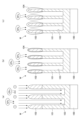
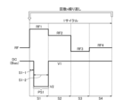
- FIG. 4 is a diagram showing an example of an RF signal and a DC signal according to the first embodiment.
- the RF signal and DC signal shown in FIG. 4 can be processed by plasma processing by the control unit 2 shown in FIGS. 1 and 2 controlling the RF power source 31 including the RF generator 31c and the DC power source 32 including the DC generator 32c. Executed by device 1.
- the RF signal has three power levels within one cycle in FIGS. 4(a) and (b). Further, the RF signal has four power levels within one cycle in FIG. 4(c).
- the RF in the upper row of FIGS. 4(a) to (c) indicates the power level of the RF signal
- the RF in the lower row indicates the pattern waveform of the RF signal having the power level in the upper row.
- the DC in the upper row of FIGS. 4(a) to (c) indicates the voltage level of the DC signal
- the DC in the lower row indicates the voltage pulse pattern of the DC signal having the voltage level in the upper row.
- the voltage pulse has a rectangular shape, but the voltage pulse is not limited to this, and may be rectangular, trapezoidal, triangular, or a combination thereof.
- n is a predetermined number of times, and is 1 or more.
- one cycle consists of periods S1, S2, and S3.
- This one cycle is an example of a "first repetition period.”
- the first repetition period has a repetition frequency of 1 kHz to 50 kHz.
- the RF signal has a first power level RF1 during a period S1.
- the RF signal has a second power level RF2 during period S2.
- the RF signal has a third power level RF3 during period S3.
- the second power level RF2 is less than the first power level RF1, and the third power level RF3 is less than the second power level RF2.
- the DC signal has two voltage levels in one cycle.
- the DC signal has a first voltage level V1 during a period T (hereinafter referred to as "offset period T") within the period S1, and has a second voltage level V2 during the remaining period within the period S1.
- the DC signal has a first voltage level V1 during periods S2 and S3.
- the offset period T is also referred to as "period S1-1.”
- a period other than the offset period T in the period S1 is also referred to as a “period S1-2.”
- the RF signal has a first power level RF1 during the first state (period S1-1) within one cycle, and has a first power level RF1 during the second state (period S1-2) within one cycle. ) has a first power level RF1.
- the RF signal also has a second power level RF2 that is lower than the first power level RF1 during the third state (period S2), and is lower than the second power level RF2 during the fourth state (period S3). It has a small third power level RF3.
- the DC signal has a first voltage level V1 during the first state (period S1-1) within one cycle, and a second voltage level V1 during the second state (period S1-2). It has a sequence of voltage pulses PS1 with voltage level V2.
- the absolute value of the second voltage level V2 is greater than the absolute value of the first voltage level V1.
- the first voltage level V1 has a zero voltage level.
- the second voltage level V2 has negative polarity.
- the DC signal has the first voltage level V1 during the third state (period S2) within one cycle, and has the first voltage level V1 during the fourth state (period S3).
- the DC signal has the first voltage level V1 during the first state (period S1-1) within one cycle, and the second state (period S1-2) and the third state (period S1-1). a sequence of voltage pulses PS1 having a second voltage level V2 during a period S2); The absolute value of the second voltage level V2 is greater than the absolute value of the first voltage level V1.
- the first voltage level V1 has a zero voltage level.
- the second voltage level V2 has negative polarity.
- the DC signal has the first voltage level V1 during the fourth state (period S3) within one cycle.
- one cycle is composed of periods S1, S2, S3, and S4. This one cycle is an example of a "first repetition period.”
- the RF signal has a first power level RF1 during the first state (period S1-1) within one cycle, and has a first power level RF1 during the second state (period S1-2) within one cycle. It has a power level RF1.
- the RF signal also has a second power level RF2 that is lower than the first power level RF1 during the third state (period S2), and is lower than the second power level RF2 during the fourth state (period S3). It has a small third power level RF3.
- the RF signal has a fourth power level RF4 that is smaller than the third power level RF3 during the fifth state (period S4).
- the DC signal has the first voltage level V1 during the first state (period S1-1) within one cycle, the second state (period S1-2), and the third state (period S1-1). a sequence of voltage pulses PS1 having a second voltage level V2 during a period S2) and a fourth state (period S3).
- the absolute value of the second voltage level V2 is greater than the absolute value of the first voltage level V1.
- the first voltage level V1 has a zero voltage level.
- the second voltage level V2 has negative polarity.
- the DC signal has the first voltage level V1 during the fifth state (period S4) within one cycle.
- FIG. 5 is a flowchart showing an example of the etching process according to the first embodiment.
- FIG. 6 is a diagram for explaining the etching process according to the first embodiment.
- the etching process of the present disclosure is controlled by the control unit 2 and executed by the plasma processing apparatus 1.
- step ST1 the control section 2 places the substrate W on the substrate support section 11 and prepares it.
- step ST2 the control unit 2 supplies an etching processing gas, supplies an RF signal having a first power level RF1 during a period S1, and a first voltage level during a period S1-1.
- a DC signal having V1 is provided.
- step ST3 the control unit 2 determines whether the offset period T has elapsed.
- the control unit 2 waits until the offset period T has elapsed and, after the elapse of the offset period T, supplies, in step ST4, a DC signal having a sequence PS1 of voltage pulses having a second voltage level V2.
- step ST5 the control unit 2 supplies the RF signal having the second power level RF2 and the DC signal having the first voltage level V1.
- step ST6 the control unit 2 supplies the RF signal having the third power level RF3 and the DC signal having the first voltage level V1.
- step ST7 the control unit 2 determines whether the set number of times n has been repeated.
- the control unit 2 repeats the processing of steps ST2 to ST6 until the set number of times n is repeated, and after repeating the number of times n, this processing ends.
- the plasma processing apparatus 1 changes the DC signal from a sequence PS1 of voltage pulses having a second voltage level V2 to a first voltage level V1 at the end of a period S1. (zero voltage level).
- the DC signal may be transitioned from the sequence PS1 of voltage pulses having a second voltage level V2 to a first voltage level V1 (zero voltage level) in time for the end of the period S2.
- the DC signal may be transitioned from the sequence PS1 of voltage pulses having a second voltage level V2 to a first voltage level V1 (zero voltage level) in time for the end of the period S3. .
- the timing at which the DC signal transitions to the voltage pulse sequence PS1 having the second voltage level V2 is after the offset period T has elapsed, but the offset period T may be "0". In this case, the DC signal is transitioned to the second voltage level V2 at the beginning of period S1. However, by making the offset period T larger than "0" and transitioning the DC signal to the second voltage level V2 after the offset period has elapsed, it is possible to improve the etching shape.
- the RF signal rises immediately after the start of period S1
- the RF signal does not reach the target power, and although it is instantaneous, it takes time to reach the target power. Therefore, at the rise of the RF signal, the plasma becomes unstable until the power reaches the first power level RF1, which is the target power, and this affects the etching shape.
- control unit 2 maintains the DC signal at the zero voltage level of the first voltage level V1 during the offset period T of the rise of the RF signal. Then, after an offset period T in which the plasma has stabilized, the DC signal transitions to a sequence of voltage pulses PS1 having a second voltage level V2.
- ions in the plasma are drawn into the recess 103 of the film 101 to be etched on the silicon substrate 100.
- the etching shape of the recess 103 can be well controlled by vertically etching the inside of the recess 103 with ions.
- a DC signal having the sequence PS1 of voltage pulses at the second voltage level V2 is supplied to the lower electrode.
- the CFx-containing deposit is deposited on the mask 102 and the upper side wall of the recess 103 of the film 101 to be etched, and the etching of the recess 103 is progressed by ions.
- the mask 102 is also etched by the ions, but since a CFx-containing deposit is deposited on the surface of the mask 102, it is possible to suppress the mask 102 from being etched by the ions.
- the DC signal is pulsed in the on state. If the DC signal is not pulsed in the on state and, for example, the DC signal having the second voltage level V2 is continuously applied during the period S1-2, the potential of the substrate W does not change. Therefore, ions cannot be drawn into the substrate W.
- the DC signal of the present disclosure has a sequence of voltage pulses PS1, for example, in period S1-2.
- the sequence of voltage pulses PS1 repeats the second voltage level V2 and the first voltage level V1 at a pulse frequency F2.
- ions can be drawn into the substrate W by the potential difference between the substrate W when a voltage at the first voltage level V1 is applied to the substrate W and when a voltage at the second voltage level V2 is applied to the substrate W.
- the sequence of voltage pulses PS1 has a pulse frequency F2 of, for example, 400 kHz.
- the voltage pulse sequence PS1 repeats the first voltage level V1 (zero voltage level) and the second voltage level V2 (negative polarity), thereby accelerating the ions.
- ions can be drawn to the bottom of the recess of the film to be etched, and the controllability of the etching shape can be improved. That is, the etching shape of the recess 103 can be improved vertically, and the etching can be promoted.
- the power of the RF signal is gradually reduced during one cycle. Plasma tends to become unstable when ignited. Therefore, in period S1, the power level is controlled to be the highest in one cycle in order to stably ignite the plasma and generate plasma with high plasma density.
- the DC signal is maintained at zero voltage level in FIG. 4(a).
- ions are not drawn into the substrate, and a CFx-containing deposit 104 is deposited on the mask 102 and the upper part of the recess 103 of the etching target film 101, as shown in FIG. 6(b).
- the RF signal is moderately controlled.
- the electron density of the generated plasma can be reduced compared to during the period S1, and the amount of the CFx-containing deposit 104 generated during etching can be reduced, and the opening of the recess 103 of the etching target film 101 can be Blockage caused by deposits 104 can be suppressed.
- the DC signal is maintained at a zero voltage level, and the RF signal is maintained at a power level that is even smaller than the power level during period S2.
- the amount of CFx deposits 104 deposited can be further reduced.
- the CFx deposit 104 can be deposited on the mask 102 without blocking the opening of the recess 103 of the film 101 to be etched. Therefore, damage to the mask 102 due to ion attraction shown in FIG. 6(a) in the next cycle can be reduced.
- the effect of the voltage pulse sequence PS1 increases relatively each time the power level of the RF signal is reduced compared to FIG. 4(a). This increases the straightness of the ions, promoting etching, and allowing the recesses 103 of the film 101 to be etched to be etched more deeply.
- the effect of the voltage pulse sequence PS1 increases in the order of the sequences shown in FIGS. 4(c), 4(b), and 4(a), the mask 102 becomes more likely to be scraped.
- the patterns shown in FIGS. 4(a) to 4(c) are repeated in multiple cycles. Thereby, it is possible to create a gradation in the balance (degree) of strength between depositing the deposit on the mask 102 and controlling the etching shape of the film 101 to be etched. That is, the balance between deposition of deposits on the mask 102 and promotion of etching of the film 101 to be etched can be controlled. Thereby, the controllability of the etching shape of the recess 103 of the film 101 to be etched can be improved.
- At least one of the pulse frequency F1, the pulse frequency F2, the RF frequency of the RF signal, and the duty ratio can be controlled.
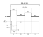
- FIG. 7 is a diagram showing an example of an RF signal and a DC signal according to the second embodiment.
- the second embodiment differs from the first embodiment in that the DC signal has a sequence PS1 of voltage pulses having a second voltage level V2 and a sequence PS2 of voltage pulses having a third voltage level V3.
- the RF signal includes three power levels within one cycle, and this cycle is repeated multiple times.
- the main cycle P is repeated k times.
- the main cycle P includes a first subcycle SP1 and a second subcycle SP2.
- the first subcycle SP1 includes a plurality of first cycles C1.
- the first cycle C1 is repeated n times in the first subcycle SP1.
- the second subcycle SP2 includes a plurality of second cycles C2.
- the second cycle C2 is repeated m times in the second subcycle SP2.
- n, m, and k are predetermined times
- n, m, and k are 1 or more.
- Each of the first cycle C1 and the second cycle C2 includes a first state S1, a second state S2, and a third state S3.
- the RF signal has a plurality of power levels that decrease stepwise in the first cycle C1 and the second cycle C2.
- the RF signal has a first power level RF1 during a first state S1 and a second power level RF2 that is less than the first power level RF1 during a second state S2. and has a third power level RF3 smaller than the second power level RF2 during the third state S3. That is, in the example of FIG. 7, the RF signal has the same pulse pattern between the first cycle C1 and the second cycle C2. Further, in the example of FIG. 7, the DC signal reaches the second voltage level V2 during the state S1-2 after the elapse of the delay time S1-1 (offset period T) in the first state S1 in the first cycle C1. A first sequence of voltage pulses PS1 having a first sequence of voltage pulses PS1.
- the DC signal generates a second sequence PS2 of voltage pulses having a third voltage level V3 during state S1-2 after a delay time S1-1 (offset period T) has elapsed in the first state S1 within the second cycle C2. has.
- the DC signal has a delay time S1-1 in both the first cycle C1 and the second cycle C2, and the first voltage level V1 during the second state S2 and the third state S3.
- the absolute value of the third voltage level V3 is smaller than the absolute value of the second voltage level V2.
- the absolute value of the first voltage level V1 is smaller than the absolute value of the third voltage level V3 and the absolute value of the second voltage level V2.
- the second voltage level V2 and the third voltage level V3 have negative polarity.
- the first voltage level V1 has a zero voltage level.
- a first subcycle in which the first repetition period is repeated a plurality of times (for example n times) and a second subcycle in which the second repetition period is repeated a plurality of times (for example m times) are alternately repeated.
- the main cycle includes a first subcycle and a second subcycle, and repeats the sequence of the first subcycle and the second subcycle executed in period P multiple times (for example, k times).
- the main cycle has a repetition frequency of 1 Hz to 10 Hz.
- the first cycle C1 within the first subcycle SP1 is composed of periods S1, S2, and S3, and is an example of a "first repeat period.”
- the RF signal has a first power level RF1 during the first state (period S1-1) in the first cycle C1 and during the second state (period S1-2). It has a first power level RF1.
- the RF pulse signal has a second power level RF2 that is smaller than the first power level RF1 during the third state (period S2), and has a second power level RF2 that is smaller than the first power level RF2 during the fourth state (period S3). also has a smaller third power level RF3.
- the first cycle C1 is repeated n times.
- the DC signal has the first voltage level V1 during the first state (period S1-1) in the first cycle C1 in the first subcycle SP1, and During a second state in C1 (period S1-2) there is a first sequence of voltage pulses PS1 having a second voltage level V2.
- the absolute value of the second voltage level V2 is greater than the absolute value of the first voltage level V1.
- the first voltage level V1 has a zero voltage level.
- the second voltage level V2 has negative polarity.
- the DC signal has the first voltage level V1 during the third state (period S2) in the first cycle C1, and has the first voltage level V1 during the fourth state (period S3) in the first cycle C1. It has level V1.
- the second cycle C2 within the second subcycle SP2 is composed of periods S1, S2, and S3, and is an example of a "second repeat period.”
- the second repetition period has a repetition frequency of 1 kHz to 50 kHz.
- the RF signal is the same between the first subcycle SP1 and the second subcycle SP2.
- the RF signal has a first power level RF1 during a first state in a second cycle C2 (period S1-1) and a first power level RF1 during a second state in a second cycle C2 (period S1-2). 1 power level RF1.
- the RF signal has a second power level RF2 during a third state within the second cycle C2 (period S2) and a third power level RF3 during a fourth state within the second cycle C2 (period S3). has.
- the DC signal has the first voltage level V1 during the first state (period S1-1) in the second cycle C2 in the second subcycle SP2.
- the second state (period S1-2) within the second cycle C2 there is a second sequence PS2 of voltage pulses having a third voltage level V3.
- the absolute value of the third voltage level V3 is greater than the absolute value of the first voltage level V1 and smaller than the absolute value of the second voltage level V2.
- Third voltage level V3 has negative polarity.
- the DC signal has the first voltage level V1 during the third state (period S2) in the second cycle C2, and has the first voltage level V1 during the fourth state (period S3) in the second cycle C2. It has level V1.
- FIG. 8 is a flowchart showing an example of the etching process according to the second embodiment.
- the etching process of the present disclosure is controlled by the control unit 2 and executed by the plasma processing apparatus 1.
- the same step numbers as the etching process of the first embodiment shown in FIG. 5 indicate the same processes, and the explanation will be simplified.
- steps ST9, ST10, ST12, and ST13 are the same processes as steps ST2, ST3, ST5, and ST6.
- step ST7 the control unit 2 determines whether the first subcycle has been repeated n times.
- step ST2 When the control unit 2 determines that the first subcycle has not been repeated n times, the process returns to step ST2 and repeats the processing of steps ST2 to ST6. As a result, the processing from the second cycle to the nth cycle of the first subcycle is executed in order.
- step ST7 when the control unit 2 determines that the first subcycle has been repeated n times, it executes the processes of steps ST9 to ST13. As a result, the first cycle of the second subcycle of period SP2 in FIG. 7 is executed.
- steps ST9 to ST13 of the second subcycle differs from the processing of steps ST2 to ST6 of the first subcycle only in step ST11. That is, in step ST4 of the first subcycle, the first sequence PS1 of voltage pulses having the second voltage level V2 is applied during the period S1-2, whereas in step ST9 of the second subcycle, the first sequence PS1 of voltage pulses having the second voltage level V2 is applied during the period S1-2. 2, a second sequence of voltage pulses PS2 having a third voltage level V3 is applied. Thereby, the amount of ions drawn can be changed between the first subcycle and the second subcycle.
- step ST14 the control unit 2 determines whether the second subcycle has been repeated m times.
- the process returns to step ST9 and repeats the processes of steps ST9 to ST13.
- the processing from the second cycle of the first subcycle to the mth cycle is executed in order.
- step ST14 when the control unit 2 determines that the second sub-cycle has been repeated m times, in step ST15, it determines whether the main cycle has been repeated k times. When the control unit 2 determines that the main cycle has not been repeated k times, the process returns to step ST2 and repeats the processes of steps ST2 to ST14. As a result, the main cycle processing of period P in FIG. 7 is repeated.
- step ST15 when the control unit 2 determines that the main cycle has been repeated k times, it ends this process.
- FIGS. 9 and 10 are diagrams showing other examples of the RF signal and DC signal according to the second embodiment.
- the RF signal has three power levels within one cycle, and this one cycle is repeated.
- the RF signal has four power levels within one cycle, and this one cycle is repeated.
- the RF signal in FIG. 9 is the same as the RF signal in FIG. 7.
- the DC signal in FIG. 9 is different from the DC signal in FIG.
- the DC signal in FIG. 7 transitions to the first voltage level V1 at the time of transition from period S1 to period S2 in the first cycle C1, which is the first repetition period, and the second cycle C2, which is the second repetition period.
- the DC signal in FIG. 9 transitions to the first voltage level V1 at the time of transition from the period S2 to the period S3 in the first cycle C1 and the second cycle C2.
- the first cycle C1 is composed of periods S1, S2, S3, and S4, and is an example of a "first repeat period.”
- the RF signal has a first power level RF1 during a first state (period S1-1) in the first cycle C1. It has a first power level RF1 during the second state (period S1-2) within the first cycle C1.
- the RF signal also has a second power level RF2 that is smaller than the first power level RF1 during the third state (period S2) within the first cycle C1.
- the RF signal has a third power level RF3 that is less than the second power level RF2 during the fourth state (period S3) in the first cycle C1, and has a third power level RF3 that is smaller than the second power level RF2 during the fifth state (period S3) in the first cycle C1.
- S4) has a fourth power level RF4 smaller than the third power level RF3.
- the DC signal has a first voltage level V1 during the first state (period S1-1) within the first cycle C1, and during the second state within the first cycle C1.
- (period S1-2) a first sequence PS1 of voltage pulses having a second voltage level V2 during a third state (period S2) and a fourth state (period S3).
- the absolute value of the second voltage level V2 is greater than the absolute value of the first voltage level V1.
- the first voltage level V1 has a zero voltage level.
- the second voltage level V2 has negative polarity.
- the DC signal has the first voltage level V1 during the fifth state (period S4) within the first cycle C1.
- the second subcycle SP2 in FIG. 10 is composed of periods S1, S2, S3, and S4, and is an example of a "second repeat period.”
- the RF signal has a first power level RF1 during the first state (period S1-1) in the second cycle C2.
- the RF signal has a first power level RF1 during a second state (period S1-2) within a second cycle C2.
- the RF signal has a second power level RF2 during the third state (period S2) within the second cycle C2.
- the RF signal has a third power level RF3 during the fourth state (period S3) within the second cycle C2.
- the RF signal has a fourth power level RF4 during the fifth state (period S4) within the second cycle C2.
- Power levels RF1-RF4 are the same between the first subcycle SP1 and the second subcycle SP2.
- the DC signal has the first voltage level V1 during the first state (period S1-1) within the second cycle C2 (one cycle), and the DC signal has the first voltage level V1 during the first state (period S1-1) within the second cycle C2 (one cycle); has a second sequence PS2 of voltage pulses having a third voltage level V3 during a second state (period S1-2), a third state (period S2) and a fourth state (period S3).
- the absolute value of the third voltage level V3 is greater than the absolute value of the first voltage level V1 and smaller than the absolute value V2 of the second voltage level V2.
- Third voltage level V3 has negative polarity.
- the DC signal then has the first voltage level V1 during the fifth state (period S4) within the second cycle C2.
- FIG. 11 is a diagram showing an example of an RF signal and a DC signal according to a modification.
- the offset period T may be longer than the period S1.
- the offset period T is longer than the period S1 and shorter than the total time of the period S1 and the period S2.
- the DC signal has a first voltage level V1 during the first state (period S1) and second state (period S2-1) within one cycle, and during the third state within one cycle.
- Period S2-2 has a sequence of voltage pulses having the second voltage level V2.
- the absolute value of the second voltage level V2 is greater than the absolute value of the first voltage level V1.
- the second voltage level V2 has negative polarity.
- the DC signal has the first voltage level V1 during the fourth state within one cycle (period S3).
- the RF signal has multiple power levels that decrease stepwise in one cycle.
- the DC signal has a first voltage level V1 during a period S1 and has a first voltage level V1 during a period S2 until an offset period T has elapsed.
- the DC signal then has a sequence of voltage pulses having a second voltage level V2 after the offset period T has elapsed.
- the DC signal has a first voltage level V1 during period S3.
- the plasma processing apparatus 1 has a power supply system used in the plasma processing apparatus 1.
- the power supply system includes an RF generator 31c and a DC generator 32c.
- An RF generator 31c for generating an RF signal is electrically connected between the first RF generator 31a and the upper electrode or the lower electrode.
- a DC generator 32c for generating a DC signal is electrically connected between the first DC generating section 32a and at least one lower electrode.
- the power supply system used in the plasma processing apparatus includes an RF generator 31c and a DC generator 32c.
- RF generator 31c is configured to generate an RF signal, the RF signal having a first power level during a first state within a first repetition period and a second power level within a first repetition period. a first power level during a third state within the first repetition period, a second power level less than the first power level during a third state within the first repetition period, and a second power level during a fourth state within the first repetition period. and a third power level that is less than the second power level.
- DC generator 32c is configured to generate a DC signal having a first voltage level during a first state within a first repetition period and a second voltage level within a first repetition period. A sequence of voltage pulses having a second voltage level therebetween, the absolute value of the second voltage level being greater than the absolute value of the first voltage level.
- DC generator 32c has a sequence of voltage pulses having a first voltage level during a third state within the first repetition period and a first voltage level during a fourth state within the first repetition period. A DC signal may also be generated.
- DC generator 32c has a sequence of voltage pulses having a second voltage level during a third state within the first repetition period and a first voltage level during a fourth state within the first repetition period.
- a DC signal may also be generated.
- the RF generator 31c may generate an RF signal having a fourth power level that is lower than the third power level during the fifth state within the first repetition period.
- DC generator 32c has a second voltage level during a third state within the first repetition period, a second voltage level during a fourth state within the first repetition period, and has a second voltage level during a fourth state within the first repetition period;
- a DC signal having a sequence of voltage pulses having a first voltage level during a fifth state of the DC signal may be generated.
- the RF generator 31c and the DC generator 32c may each generate an RF signal and a DC signal as follows.
- the RF signal has a first power level RF1 during a first state within a second repetition period.
- the RF signal has a first power level RF1 during a second state within a second repetition period.
- the RF signal has said second power level RF2 during a third state within a second repetition period.
- the RF signal has a third power level RF3 during the fourth state within the second repetition period.
- the DC signal has a first voltage level during a first state within a second repetition period.
- the DC signal has a sequence of voltage pulses having a third voltage level during a second state within a second repetition period.
- the absolute value of the third voltage level is greater than the absolute value of the first voltage level and smaller than the absolute value of the second voltage level.
- the plasma processing apparatus 1 is coupled to a plasma processing chamber 10, a substrate support 11 disposed within the plasma processing chamber 10, and has a power level gradually reduced from a first power level during a repetition period.
- an RF generator 31c configured to generate an RF signal having a plurality of power levels and coupled to the substrate support 11 and configured to generate a sequence of voltage pulses during a pulse generation state within a repetition period; and a DC generator 32c in which the start time of the pulse generation state is offset with respect to the start time of the first power level.
- the pulse generation state may be started after the end of the first power level.
- timing of changing the DC signal to the first voltage level may be slightly shifted from the end of period S2 (in the example of FIG. 11, the end of period S3).
- Modifications 1 to 7 will be described with reference to FIGS. 12 to 18.
- the RF signal is generated by the RF generator 31c.
- the DC signal is generated by DC generator 32c.
- FIG. 12 is a diagram showing an example of an RF signal and a DC signal according to modification example 1.
- the RF signal has the first power level RF1 during the first state (period S1-1) and second state (period S1-2) within the first repetition period (one cycle).
- the RF signal also has a second power level RF2 that is smaller than the first power level during a third state (period S2) within the first repetition period.
- the RF signal also has a third power level RF3 that is smaller than the first power level RF1 and larger than the second power level RF2 during a fourth state (period S3) within the first repetition period.
- the DC signal has a first voltage level V1 during a first state (period S1-1) within a first repetition period (1 cycle), and has a first voltage level V1 during a first state (period S1-2) within the first repetition period (period S1-2). has a sequence of voltage pulses PS1 having a second voltage level V2 between them.
- the absolute value of the second voltage level V2 is greater than the absolute value of the first voltage level V1.
- the DC signal may have a first voltage level V1 during a third state (period S2) and a fourth state (period S3) within the first repetition period.
- the DC signal has a sequence of voltage pulses PS1 having a second voltage level V2 during a third state (period S2) within the first repetition period and a sequence PS1 of voltage pulses having a second voltage level V2 during a third state (period S3) within the first repetition period.
- a first voltage level V1 may be provided therebetween.
- the DC signal may have a sequence PS1 of voltage pulses having a second voltage level V2 during a third state (period S2) and a fourth state (period S3) within the first repetition period.
- FIG. 13 is a diagram showing an example of an RF signal and a DC signal according to Modification 2.
- the RF signal may have a fourth power level RF4 that is less than the second power level RF2 during the fifth state (period S4) within the first repetition period.
- FIG. 14 is a diagram showing an example of an RF signal and a DC signal according to Modification 3. As shown in FIG. 14, the RF signal has a fourth power level RF4 greater than the second power level RF2 and less than the third power level RF3 during the fifth state (period S4) within the first repetition period. May have.
- FIG. 15 is a diagram showing an example of an RF signal and a DC signal according to modification example 4.
- the RF signal has a fourth power level RF4 greater than the third power level RF3 and less than the first power level RF1 during the fifth state (period S4) within the first repetition period. May have.
- the DC signal may have a first voltage level V1 during a third state (period S2), a fourth state (period S3), and a fifth state (period S4) within the first repetition period.
- the DC signal has a sequence PS1 of voltage pulses having a second voltage level V2 during a third state (period S2) within the first repetition period, a fourth state (period S3) within the first repetition period and The first voltage level V1 may be maintained during the fifth state (period S4).
- the DC signal has a sequence PS1 of voltage pulses having a second voltage level V2 during a third state (period S2) and a fourth state (period S3) within the first repetition period;
- the first voltage level V1 may be maintained during the fifth state (period S4).
- the DC signal has a sequence PS1 of voltage pulses having a second voltage level V2 during a third state (period S2), a fourth state (period S3) and a fifth state (period S4) within the first repetition period. You may.
- the second voltage level V2 may have negative polarity.
- the first voltage level V1 may have a zero voltage level.
- the first repetition period may have a repetition frequency of 1 kHz to 50 kHz.
- the sequence of voltage pulses PS1 may have a pulse frequency of 300kHz to 600kHz.
- FIG. 16 is a diagram showing an example of an RF signal and a DC signal according to modification 5.
- the RF signal has the first power level RF1 during the first state (period S1-1) and second state (period S1-2) within the first repetition period (one cycle).
- the RF signal also has a second power level RF2 that is smaller than the first power level RF1 during a third state (period S2) within the first repetition period.
- the RF signal also has a third power level RF3 that is smaller than the second power level RF2 during the fourth state (period S3) within the first repetition period.
- the RF signal also has a fourth power level RF4 that is greater than the third power level RF3 during the fifth state (period S4) within the first repetition period.
- the DC signal has a first voltage level V1 during a first state (period S1-1) within a first repetition period (1 cycle), and has a first voltage level V1 during a first state (period S1-2) within the first repetition period (period S1-2). has a sequence of voltage pulses PS1 having a second voltage level V2 between them.
- the absolute value of the second voltage level V2 is greater than the absolute value of the first voltage level V1.
- the fourth power level RF4 may be smaller than the second power level RF2.
- the fourth power level RF4 may be smaller than the first power level RF1 and larger than the second power level RF2.
- the DC signal has a first voltage level V1 during the third state (period S2), fourth state (period S3), and fifth state (period S4) within the first repetition period. May have.
- the DC signal has a sequence PS1 of voltage pulses having a second voltage level V2 during a third state (period S2) within the first repetition period, a fourth state (period S3) within the first repetition period and The first voltage level V1 may be maintained during the fifth state (period S4).
- the DC signal has a sequence PS1 of voltage pulses having a second voltage level V2 during a third state (period S2) and a fourth state (period S3) within the first repetition period;
- the first voltage level V1 may be maintained during the fifth state (period S4).
- the DC signal has a sequence PS1 of voltage pulses having a second voltage level V2 during a third state (period S2), a fourth state (period S3) and a fifth state (period S4) within the first repetition period. You may.
- the second voltage level V2 may have negative polarity.
- the first voltage level V1 may have a zero voltage level.
- the first repetition period may have a repetition frequency of 1 kHz to 50 kHz.
- the sequence of voltage pulses PS1 may have a pulse frequency of 300kHz to 600kHz.
- FIG. 17 is a diagram illustrating an example of an RF signal and a DC signal according to modification 6.
- the RF signal has a first power level RF1 during a first state (period S1) within a first repetition period (1 cycle), and has a first power level RF1 during a second state (period S1) within the first repetition period (1 cycle).
- a second power level RF2 that is less than the first power level RF1 during S2) and a third power level that is less than the second power level RF2 during a third state (period S3) within the first repetition period; It has RF3.
- the DC signal has a sequence of voltage pulses PS1 having a first voltage level V1 during a first state (period S1) within a first repetition period.
- the DC signal has a second voltage level V2 during a second state (period S2) and a third state (period S3) within the first repetition period, and the absolute value of the second voltage level V2 is equal to the first voltage. It is smaller than the absolute value of level V1.
- the DC signal has a sequence PS1 of voltage pulses having a first voltage level V1 during a second state (period S2) within a first repetition period and a sequence PS1 of voltage pulses having a first voltage level V1 during a second state (period S3) within the first repetition period.
- a second voltage level V2 may be provided therebetween, and the absolute value of the second voltage level V2 may be smaller than the absolute value of the first voltage level V1.
- the DC signal may have a sequence PS1 of voltage pulses having a first voltage level V1 during a second state (period S2) and a third state (period S3) within the first repetition period.
- the RF signal may have a fourth power level RF4 that is less than the third power level RF3 during a fourth state (period S4) within the first repetition period.
- the RF signal may have a fourth power level RF4 greater than the third power level RF3 during a fourth state (period S4) within the first repetition period.
- Fourth power level RF4 may be smaller than second power level RF2.
- the fourth power level RF4 may be smaller than the first power level RF1 and larger than the second power level RF2.
- the DC signal has a second voltage level V2 during a second state (period S2), a third state (period S3) and a fourth state (period S4) within the first repetition period;
- the absolute value of may be smaller than the absolute value of the first voltage level V1.
- the DC signal has a sequence PS1 of voltage pulses having a first voltage level V1 during a second state (period S2) within a first repetition period, a third state (period S3) within the first repetition period and A second voltage level V2 may be provided during the fourth state (period S4), and the absolute value of the second voltage level V2 may be smaller than the absolute value of the first voltage level V1.
- the DC signal has a sequence PS1 of voltage pulses having a first voltage level V1 during a second state (period S2) and a third state (period S3) within a first repetition period;
- a second voltage level V2 may be provided during the fourth state (period S4), and the absolute value of the second voltage level V2 may be smaller than the absolute value of the first voltage level V1.
- the DC signal has a sequence PS1 of voltage pulses having a first voltage level V1 during a second state (period S2), a third state (period S3) and a fourth state (period S4) within the first repetition period. You may.
- FIG. 18 is a diagram showing an example of an RF signal and a DC signal according to modification example 7.
- the RF signal has a first power level RF1 during a first state (period S1) within a first repetition period (1 cycle), and has a first power level RF1 during a second state (period S1) within the first repetition period (1 cycle).
- S2) has a second power level RF2 smaller than the first power level RF1, and during a third state (period S3) within the first repetition period has a second power level RF2 smaller than the first power level RF1 and a second power level RF1 during the third state (period S3) within the first repetition period.
- It has a third power level RF3 that is greater than level RF2.
- the DC signal has a sequence of voltage pulses PS1 having a first voltage level V1 during a first state (period S1) within a first repetition period.
- the DC signal has a second voltage level V2 during a second state (period S2) and a third state (period S3) within the first repetition period, and the absolute value of the second voltage level V2 is equal to the first voltage. It is smaller than the absolute value of level V1.
- the DC signal has a sequence PS1 of voltage pulses having a first voltage level V1 during a second state (period S2) within a first repetition period and a sequence PS1 of voltage pulses having a first voltage level V1 during a second state (period S3) within the first repetition period.
- a second voltage level V2 is provided therebetween, and the absolute value of the second voltage level V2 may be smaller than the absolute value of the first voltage level V1.
- the DC signal may have a sequence PS1 of voltage pulses having a first voltage level V1 during a second state (period S2) and a third state (period S3) within the first repetition period.
- the RF signal may have a fourth power level RF4 that is less than the second power level RF2 during a fourth state (period S4) within the first repetition period.
- the RF signal may have a fourth power level RF4 greater than the second power level RF2 and less than the third power level RF3 during a fourth state (period S4) within the first repetition period.
- the RF signal may have a fourth power level RF4 greater than the third power level RF3 and less than the first power level RF1 during a fourth state (period S4) within the first repetition period.
- the DC signal has a second voltage level V2 during a second state (period S2), a third state (period S3) and a fourth state (period S4) within the first repetition period;
- the absolute value of may be smaller than the absolute value of the first voltage level V1.
- the DC signal has a sequence PS1 of voltage pulses having a first voltage level V1 during a second state (period S2) within a first repetition period, a third state (period S3) within the first repetition period and A second voltage level V2 may be provided during the fourth state (period S4), and the absolute value of the second voltage level V2 may be smaller than the absolute value of the first voltage level V1.
- the DC signal has a sequence PS1 of voltage pulses having a first voltage level V1 during a second state (period S2) and a third state (period S3) within a first repetition period;
- a second voltage level V2 may be provided during the fourth state (period S4), and the absolute value of the second voltage level V2 may be smaller than the absolute value of the first voltage level V1.
- the DC signal has a sequence PS1 of voltage pulses having a first voltage level V1 during a second state (period S2), a third state (period S3) and a fourth state (period S4) within the first repetition period. You may.
- a plasma processing chamber comprising: a substrate support disposed within the plasma processing chamber and including a lower electrode; an upper electrode disposed above the substrate support part; an RF power source configured to provide an RF signal to the top electrode or the bottom electrode, the RF signal having a first power level during a first state within a first repetition period; a first power level during a second state within one repetition period; and a second power level less than the first power level during a third state within the first repetition period; an RF power source having a third power level less than the second power level during a fourth state within one repetition period; a DC power supply configured to apply a DC signal to the bottom electrode, the DC signal having a first voltage level during the first state within the first repetition period; a DC power supply having a sequence of voltage pulses having a second voltage level during the second state within a time period, the absolute value of the second voltage level being greater than the absolute value of the first voltage level;
- a plasma processing apparatus comprising:
- Appendix 5 The plasma processing apparatus according to appendix 4, wherein the voltage pulse sequence has a pulse frequency of 300 kHz to 600 kHz.
- the DC signal has the first voltage level during the third state within the first repetition period and has the first voltage level during the fourth state within the first repetition period;
- the DC signal has the second voltage level during the third state within the first repetition period and has the first voltage level during the fourth state within the first repetition period;
- the DC signal has the second voltage level during the third state within the first repetition period and has the second voltage level during the fourth state within the first repetition period. , having the first voltage level during the fifth state within the first repetition period.
- the RF signal has the first power level during a first state within a second repetition period, has the first power level during a second state within the second repetition period, and has the first power level during a second state within the second repetition period. having the second power level during a third state within two repetition periods, and having the third power level during a fourth state within the second repetition period;
- the DC signal has a voltage pulse having the first voltage level during the first state within the second repetition period and a third voltage level during the second state within the second repetition period. has a sequence of The plasma processing apparatus according to any one of Supplementary Notes 2 to 5, wherein the absolute value of the third voltage level is greater than the absolute value of the first voltage level and smaller than the absolute value of the second voltage level. .
- Appendix 11 The plasma processing apparatus according to appendix 10, wherein a first subcycle in which the first repetition period is repeated a plurality of times and a second subcycle in which the second repetition period is repeated a plurality of times are alternately repeated.
- Appendix 12 The plasma processing apparatus according to appendix 11, wherein the main cycle including the first subcycle and the second subcycle has a repetition frequency of 1 Hz to 10 Hz.
- a power supply system used in a plasma processing equipment an RF generator configured to generate an RF signal, the RF signal having a first power level during a first state within a first repetition period; and a second power level within the first repetition period; having the first power level during a state, and having a second power level less than the first power level during a third state within the first repetition period, and having a second power level less than the first power level during a third state within the first repetition period.
- an RF generator having a third power level less than the second power level during four states; a DC generator configured to generate a DC signal, the DC signal having a first voltage level during the first state within the first repetition period; a DC generator having a sequence of voltage pulses having a second voltage level during the second state, the absolute value of the second voltage level being greater than the absolute value of the first voltage level; Power system.
- the DC signal has the first voltage level during the third state within the first repetition period and has the first voltage level during the fourth state within the first repetition period. 14.
- the DC signal has the second voltage level during the third state within the first repetition period and has the first voltage level during the fourth state within the first repetition period. 14.
- the DC signal has the second voltage level during the third state within the first repetition period and has the second voltage level during the fourth state within the first repetition period. , a sequence of voltage pulses having the first voltage level during the fifth state within the first repetition period.
- the RF signal has the first power level during a first state within a second repetition period, has the first power level during a second state within the second repetition period, and has the first power level during a second state within the second repetition period. having the second power level during a third state within two repetition periods, and having the third power level during a fourth state within the second repetition period;
- the DC signal has a voltage pulse having the first voltage level during the first state within the second repetition period and a third voltage level during the second state within the second repetition period. has a sequence of 14.
- a plasma processing apparatus comprising:
- a power supply system used in a plasma processing equipment an RF generator configured to generate an RF signal, the RF signal having a first power level between a first state and a second state within a first repetition period; a second power level that is less than the first power level during a third state within the repeat period; and a second power level that is less than the first power level and the second power during a fourth state within the first repetition period.
- an RF generator having a third power level greater than the power level; a DC generator configured to generate a DC signal, the DC signal having a first voltage level during the first state within the first repetition period; a DC generator having a sequence of voltage pulses having a second voltage level during the second state, the absolute value of the second voltage level being greater than the absolute value of the first voltage level; Power system.
- the DC signal has a sequence of voltage pulses having the second voltage level during the third state within the first repetition period and having the second voltage level during the fourth state within the first repetition period. 22.
- the DC signal has a sequence of voltage pulses having the second voltage level during the third state within the first repetition period, the fourth state and the fifth state within the first repetition period.
- the power supply system according to any one of appendices 25 to 27, having the first voltage level between.
- the DC signal has a sequence of voltage pulses having the second voltage level during the third state and the fourth state within the first repetition period and the fifth state within the first repetition period.
- the power supply system according to any one of appendices 25 to 27, having the first voltage level between.
- Appendix 34 The power supply system according to any one of appendices 21 to 33, wherein the first repetition period has a repetition frequency of 1 kHz to 50 kHz.
- a power supply system used in a plasma processing equipment an RF generator configured to generate an RF signal, the RF signal having a first power level between a first state and a second state within a first repetition period; a second power level that is less than the first power level during a third state within the repeat period, and a third power level that is less than the second power level during a fourth state within the first repeat period.
- a DC generator configured to generate a DC signal, the DC signal having a first voltage level during the first state within the first repetition period; a DC generator having a sequence of voltage pulses having a second voltage level during the second state, the absolute value of the second voltage level being greater than the absolute value of the first voltage level; Power system.
- the DC signal has a sequence of voltage pulses having the second voltage level during the third state within the first repetition period, the fourth state and the fifth state within the first repetition period. 39.
- the power supply system according to any one of appendices 36 to 38, having the first voltage level between.
- the DC signal has a sequence of voltage pulses having the second voltage level during the third state and the fourth state within the first repetition period and the fifth state within the first repetition period.
- 39. The power supply system according to any one of appendices 36 to 38, wherein the power supply system has the first voltage level between .
- Appendix 46 46.
- a power supply system used in a plasma processing equipment an RF generator configured to generate an RF signal, the RF signal having a first power level during a first state within a first repetition period; and a second power level within the first repetition period; RF generation having a second power level less than the first power level during a state and having a third power level less than the second power level during a third state within the first repetition period.
- the vessel and a DC generator configured to generate a DC signal, the DC signal having a sequence of voltage pulses having a first voltage level during the first state within the first repetition period; The vessel and Equipped with a power system.
- the DC signal has the second voltage level between the second state and the third state within the first repetition period, and the absolute value of the second voltage level is equal to the absolute value of the first voltage level.
- the DC signal has a sequence of voltage pulses having a first voltage level during the second state within the first repetition period and having a first voltage level during the third state within the first repetition period.
- the power supply system according to claim 47 having a voltage level, wherein the absolute value of the second voltage level is smaller than the absolute value of the first voltage level.
- the DC signal has the second voltage level during the second state, the third state, and the fourth state within the first repetition period, and the absolute value of the second voltage level is equal to the absolute value of the second voltage level.
- 55. The power supply system according to any one of appendices 51 to 54, wherein the power supply system is smaller than the absolute value of one voltage level.
- the DC signal has a sequence of voltage pulses having the first voltage level during the second state within the first repetition period, the third state and the fourth state within the first repetition period.
- 55. The power supply system according to any one of appendices 51 to 54, wherein the second voltage level is between 1 and 2, and the absolute value of the second voltage level is smaller than the absolute value of the first voltage level.
- the DC signal has a sequence of voltage pulses having the first voltage level during the second state and the third state within the first repetition period and the fourth state within the first repetition period.
- 55. The power supply system according to any one of appendices 51 to 54, wherein the second voltage level is between 1 and 2, and the absolute value of the second voltage level is smaller than the absolute value of the first voltage level.
- a power supply system used in a plasma processing equipment an RF generator configured to generate an RF signal, the RF signal having a first power level during a first state within a first repetition period; and a second power level within the first repetition period; a second power level that is less than the first power level during the state, and that is less than the first power level and greater than the second power level during a third state within the first repetition period; an RF generator having a third power level; a DC generator configured to generate a DC signal, the DC signal having a sequence of voltage pulses having a first voltage level during the first state within the first repetition period;
- the vessel and Equipped with a power system An RF generator configured to generate an RF signal, the RF signal having a first power level during a first state within a first repetition period; and a second power level within the first repetition period; a second power level that is less than the first power level during the state, and that is less than the first power level and greater than the second power level during a third state within the first repetition period; an
- the DC signal has the second voltage level between the second state and the third state within the first repetition period, and the absolute value of the second voltage level is equal to the absolute value of the first voltage level.
- the DC signal has a sequence of voltage pulses having a first voltage level during the second state within the first repetition period and having a first voltage level during the third state within the first repetition period.
- the power supply system according to claim 59 having a voltage level, wherein the absolute value of the second voltage level is smaller than the absolute value of the first voltage level.
- the DC signal has a second voltage level between the second state, the third state, and the fourth state within the first repetition period, and the absolute value of the second voltage level is equal to the first
- the power supply system according to any one of appendices 63 to 65, wherein the voltage level is smaller than the absolute value.
- the DC signal has a sequence of voltage pulses having the first voltage level during the second state within the first repetition period, the third state and the fourth state within the first repetition period.
- the power supply system according to any one of attachments 63 to 65, wherein the second voltage level is between 1 and 2, and the absolute value of the second voltage level is smaller than the absolute value of the first voltage level.
- the DC signal has a sequence of voltage pulses having the first voltage level during the second state and the third state within the first repetition period and the fourth state within the first repetition period.
- 66 The power supply system according to any one of attachments 63 to 65, wherein the second voltage level is between 1 and 2, and the absolute value of the second voltage level is smaller than the absolute value of the first voltage level.
- the present invention is not limited to the configurations shown in the above embodiments, such as combinations with other elements, and the like. These points can be modified without departing from the spirit of the present invention, and can be appropriately determined depending on the application thereof. Moreover, the matters described in the plurality of embodiments can be configured in other ways without being inconsistent, and can be combined without being inconsistent.
- a capacitively coupled plasma device has been described as an example, but the present invention is not limited to this and may be applied to other plasma devices.
- an inductively coupled plasma (ICP) device may be used instead of a capacitively coupled plasma device.
- the inductively coupled plasma device includes an antenna and a lower electrode.
- the bottom electrode is disposed within the substrate support and the antenna is disposed at or above the chamber.
- An RF generator is then coupled to the antenna and a DC generator is coupled to the bottom electrode.
- the RF generator is thus coupled to the top electrode of a capacitively coupled plasma device or to the antenna of an inductively coupled plasma device. That is, an RF generator is coupled to plasma processing chamber 10.
- Plasma processing apparatus Control section 2a Computer 2a1 Processing section 2a2 Storage section 2a3 Communication interface 10 Plasma processing chamber 11 Substrate support section 12 Plasma generation section 13 shower head 20 Gas supply section 30 Power supply 31 RF power supply 31a First RF generation section 31b Second RF generator 31c RF generator 32 DC power supply 32a First DC generator 32b Second DC generator 32c DC generator 40 Exhaust system
Landscapes
- Physics & Mathematics (AREA)
- Engineering & Computer Science (AREA)
- Plasma & Fusion (AREA)
- Chemical & Material Sciences (AREA)
- Analytical Chemistry (AREA)
- Electromagnetism (AREA)
- Spectroscopy & Molecular Physics (AREA)
- Drying Of Semiconductors (AREA)
- Plasma Technology (AREA)
Priority Applications (5)
| Application Number | Priority Date | Filing Date | Title |
|---|---|---|---|
| JP2024537629A JPWO2024024594A1 (https=) | 2022-07-28 | 2023-07-19 | |
| CN202380055337.XA CN119585855A (zh) | 2022-07-28 | 2023-07-19 | 等离子体处理装置和电源系统 |
| KR1020257005155A KR20250044879A (ko) | 2022-07-28 | 2023-07-19 | 플라즈마 처리 장치 및 전원 시스템 |
| TW112127268A TW202422629A (zh) | 2022-07-28 | 2023-07-21 | 電漿處理裝置及電源系統 |
| US19/037,464 US20250174434A1 (en) | 2022-07-28 | 2025-01-27 | Plasma processing apparatus and power supply system |
Applications Claiming Priority (2)
| Application Number | Priority Date | Filing Date | Title |
|---|---|---|---|
| JP2022-120800 | 2022-07-28 | ||
| JP2022120800 | 2022-07-28 |
Related Child Applications (1)
| Application Number | Title | Priority Date | Filing Date |
|---|---|---|---|
| US19/037,464 Continuation US20250174434A1 (en) | 2022-07-28 | 2025-01-27 | Plasma processing apparatus and power supply system |
Publications (1)
| Publication Number | Publication Date |
|---|---|
| WO2024024594A1 true WO2024024594A1 (ja) | 2024-02-01 |
Family
ID=89706292
Family Applications (1)
| Application Number | Title | Priority Date | Filing Date |
|---|---|---|---|
| PCT/JP2023/026442 Ceased WO2024024594A1 (ja) | 2022-07-28 | 2023-07-19 | プラズマ処理装置及び電源システム |
Country Status (6)
| Country | Link |
|---|---|
| US (1) | US20250174434A1 (https=) |
| JP (1) | JPWO2024024594A1 (https=) |
| KR (1) | KR20250044879A (https=) |
| CN (1) | CN119585855A (https=) |
| TW (1) | TW202422629A (https=) |
| WO (1) | WO2024024594A1 (https=) |
Cited By (3)
| Publication number | Priority date | Publication date | Assignee | Title |
|---|---|---|---|---|
| WO2025203684A1 (ja) * | 2024-03-29 | 2025-10-02 | 株式会社ダイヘン | 高周波電源装置 |
| WO2025203685A1 (ja) * | 2024-03-29 | 2025-10-02 | 株式会社ダイヘン | 高周波電力供給システム |
| WO2026034233A1 (ja) * | 2024-08-08 | 2026-02-12 | 東京エレクトロン株式会社 | プラズマ処理装置及び電源システム |
Citations (3)
| Publication number | Priority date | Publication date | Assignee | Title |
|---|---|---|---|---|
| JP2013535074A (ja) * | 2010-06-11 | 2013-09-09 | バリアン・セミコンダクター・エクイップメント・アソシエイツ・インコーポレイテッド | 基板プラズマ処理技術 |
| JP2021534544A (ja) * | 2018-08-30 | 2021-12-09 | 東京エレクトロン株式会社 | プラズマ処理のための制御のシステム及び方法 |
| JP2022041874A (ja) * | 2020-08-31 | 2022-03-11 | 東京エレクトロン株式会社 | プラズマ処理装置及びプラズマ処理方法 |
Family Cites Families (23)
| Publication number | Priority date | Publication date | Assignee | Title |
|---|---|---|---|---|
| US8070972B2 (en) * | 2006-03-30 | 2011-12-06 | Tokyo Electron Limited | Etching method and etching apparatus |
| JP6027490B2 (ja) * | 2013-05-13 | 2016-11-16 | 東京エレクトロン株式会社 | ガスを供給する方法、及びプラズマ処理装置 |
| JP6030994B2 (ja) * | 2013-05-15 | 2016-11-24 | 東京エレクトロン株式会社 | プラズマエッチング装置及びプラズマエッチング方法 |
| JP6158111B2 (ja) * | 2014-02-12 | 2017-07-05 | 東京エレクトロン株式会社 | ガス供給方法及び半導体製造装置 |
| JP6284786B2 (ja) * | 2014-02-27 | 2018-02-28 | 東京エレクトロン株式会社 | プラズマ処理装置のクリーニング方法 |
| JP6541596B2 (ja) * | 2016-03-22 | 2019-07-10 | 東京エレクトロン株式会社 | プラズマ処理方法 |
| JP6670791B2 (ja) * | 2017-03-30 | 2020-03-25 | 東京エレクトロン株式会社 | 流量制御器を検査する方法及び被処理体を処理する方法 |
| JP2019129123A (ja) * | 2018-01-26 | 2019-08-01 | 東京エレクトロン株式会社 | 直流電圧を印加する方法及びプラズマ処理装置 |
| JP7250449B2 (ja) * | 2018-07-04 | 2023-04-03 | 東京エレクトロン株式会社 | プラズマエッチング方法及びプラズマエッチング装置 |
| US11605527B2 (en) * | 2020-01-20 | 2023-03-14 | COMET Technologies USA, Inc. | Pulsing control match network |
| JP7442365B2 (ja) * | 2020-03-27 | 2024-03-04 | 東京エレクトロン株式会社 | 基板処理装置、基板処理システム、基板処理装置の制御方法および基板処理システムの制御方法 |
| JP7433271B2 (ja) * | 2020-04-27 | 2024-02-19 | 東京エレクトロン株式会社 | 基板処理装置および基板処理装置の制御方法 |
| JP7504004B2 (ja) * | 2020-11-13 | 2024-06-21 | 東京エレクトロン株式会社 | 基板処理装置及び基板処理方法 |
| JP7560215B2 (ja) * | 2021-03-17 | 2024-10-02 | 東京エレクトロン株式会社 | プラズマ処理装置 |
| JP7544450B2 (ja) * | 2021-03-17 | 2024-09-03 | 東京エレクトロン株式会社 | プラズマ処理装置 |
| JP7648307B2 (ja) * | 2021-06-22 | 2025-03-18 | 東京エレクトロン株式会社 | シャワーヘッド及びプラズマ処理装置 |
| JP7761537B2 (ja) * | 2022-07-20 | 2025-10-28 | 東京エレクトロン株式会社 | プラズマ処理装置及びプラズマ処理方法 |
| WO2024038774A1 (ja) * | 2022-08-16 | 2024-02-22 | 東京エレクトロン株式会社 | プラズマ処理装置及び静電チャック |
| WO2024043065A1 (ja) * | 2022-08-22 | 2024-02-29 | 東京エレクトロン株式会社 | プラズマ処理装置、rfシステム、およびrf制御方法 |
| US12266506B2 (en) * | 2022-09-07 | 2025-04-01 | Applied Materials, Inc. | Scanning impedance measurement in a radio frequency plasma processing chamber |
| US20240145215A1 (en) * | 2022-10-28 | 2024-05-02 | Applied Materials, Inc. | Pulsed voltage plasma processing apparatus and method |
| US12580155B2 (en) * | 2022-12-07 | 2026-03-17 | Applied Materials, Inc. | Learning based tuning in a radio frequency plasma processing chamber |
| JPWO2024171714A1 (https=) * | 2023-02-14 | 2024-08-22 |
-
2023
- 2023-07-19 WO PCT/JP2023/026442 patent/WO2024024594A1/ja not_active Ceased
- 2023-07-19 CN CN202380055337.XA patent/CN119585855A/zh active Pending
- 2023-07-19 JP JP2024537629A patent/JPWO2024024594A1/ja active Pending
- 2023-07-19 KR KR1020257005155A patent/KR20250044879A/ko active Pending
- 2023-07-21 TW TW112127268A patent/TW202422629A/zh unknown
-
2025
- 2025-01-27 US US19/037,464 patent/US20250174434A1/en active Pending
Patent Citations (3)
| Publication number | Priority date | Publication date | Assignee | Title |
|---|---|---|---|---|
| JP2013535074A (ja) * | 2010-06-11 | 2013-09-09 | バリアン・セミコンダクター・エクイップメント・アソシエイツ・インコーポレイテッド | 基板プラズマ処理技術 |
| JP2021534544A (ja) * | 2018-08-30 | 2021-12-09 | 東京エレクトロン株式会社 | プラズマ処理のための制御のシステム及び方法 |
| JP2022041874A (ja) * | 2020-08-31 | 2022-03-11 | 東京エレクトロン株式会社 | プラズマ処理装置及びプラズマ処理方法 |
Cited By (3)
| Publication number | Priority date | Publication date | Assignee | Title |
|---|---|---|---|---|
| WO2025203684A1 (ja) * | 2024-03-29 | 2025-10-02 | 株式会社ダイヘン | 高周波電源装置 |
| WO2025203685A1 (ja) * | 2024-03-29 | 2025-10-02 | 株式会社ダイヘン | 高周波電力供給システム |
| WO2026034233A1 (ja) * | 2024-08-08 | 2026-02-12 | 東京エレクトロン株式会社 | プラズマ処理装置及び電源システム |
Also Published As
| Publication number | Publication date |
|---|---|
| TW202422629A (zh) | 2024-06-01 |
| KR20250044879A (ko) | 2025-04-01 |
| US20250174434A1 (en) | 2025-05-29 |
| JPWO2024024594A1 (https=) | 2024-02-01 |
| CN119585855A (zh) | 2025-03-07 |
Similar Documents
| Publication | Publication Date | Title |
|---|---|---|
| WO2024024594A1 (ja) | プラズマ処理装置及び電源システム | |
| US20240153742A1 (en) | Plasma processing method and plasma processing apparatus | |
| JP2024013548A (ja) | プラズマ処理装置及びプラズマ処理方法 | |
| US20220406568A1 (en) | Plasma processing method and plasma processing apparatus | |
| TW202425051A (zh) | 蝕刻方法及電漿處理裝置 | |
| JP7828799B2 (ja) | プラズマ処理装置及びプラズマ処理方法 | |
| TW202309972A (zh) | 電漿處理裝置及rf系統 | |
| JP2023172255A (ja) | プラズマ処理装置及びプラズマ処理方法 | |
| JP2022115719A (ja) | プラズマ処理装置及びプラズマ処理方法 | |
| TW202503829A (zh) | 電漿處理裝置 | |
| JP7378668B2 (ja) | 静電チャックおよび基板処理装置 | |
| WO2023210399A1 (ja) | プラズマ処理装置、電源システム及びプラズマ処理方法 | |
| WO2023204101A1 (ja) | プラズマ処理装置及びプラズマ処理方法 | |
| JP2024013617A (ja) | 基板処理装置 | |
| TW202224021A (zh) | 基板處理裝置及基板處理方法 | |
| JP7725267B2 (ja) | プラズマ処理装置及びプラズマ処理方法 | |
| JP7739425B2 (ja) | プラズマ処理装置及びプラズマ処理方法 | |
| JP2024035702A (ja) | プラズマ処理装置及びプラズマ処理方法 | |
| KR20250165342A (ko) | 에칭 장치 및 에칭 방법 | |
| WO2023189292A1 (ja) | プラズマ処理装置 | |
| TW202529161A (zh) | 電漿處理裝置 | |
| TW202431327A (zh) | 電漿處理裝置及電源系統 | |
| TW202533285A (zh) | 電漿蝕刻裝置及電漿蝕刻方法 | |
| JP2023163625A (ja) | プラズマ処理装置及びプラズマ処理方法 | |
| WO2025126872A1 (ja) | ガス供給装置、シャワーヘッド、および配管 |
Legal Events
| Date | Code | Title | Description |
|---|---|---|---|
| 121 | Ep: the epo has been informed by wipo that ep was designated in this application |
Ref document number: 23846325 Country of ref document: EP Kind code of ref document: A1 |
|
| WWE | Wipo information: entry into national phase |
Ref document number: 2024537629 Country of ref document: JP |
|
| WWE | Wipo information: entry into national phase |
Ref document number: 202380055337.X Country of ref document: CN |
|
| ENP | Entry into the national phase |
Ref document number: 20257005155 Country of ref document: KR Kind code of ref document: A |
|
| NENP | Non-entry into the national phase |
Ref country code: DE |
|
| WWP | Wipo information: published in national office |
Ref document number: 202380055337.X Country of ref document: CN |
|
| WWP | Wipo information: published in national office |
Ref document number: 1020257005155 Country of ref document: KR |
|
| 122 | Ep: pct application non-entry in european phase |
Ref document number: 23846325 Country of ref document: EP Kind code of ref document: A1 |