WO2024024385A1 - 非水電解質二次電池 - Google Patents
非水電解質二次電池 Download PDFInfo
- Publication number
- WO2024024385A1 WO2024024385A1 PCT/JP2023/024249 JP2023024249W WO2024024385A1 WO 2024024385 A1 WO2024024385 A1 WO 2024024385A1 JP 2023024249 W JP2023024249 W JP 2023024249W WO 2024024385 A1 WO2024024385 A1 WO 2024024385A1
- Authority
- WO
- WIPO (PCT)
- Prior art keywords
- negative electrode
- active material
- protective tape
- positive electrode
- secondary battery
- Prior art date
- Legal status (The legal status is an assumption and is not a legal conclusion. Google has not performed a legal analysis and makes no representation as to the accuracy of the status listed.)
- Ceased
Links
Images



Classifications
-
- H—ELECTRICITY
- H01—ELECTRIC ELEMENTS
- H01M—PROCESSES OR MEANS, e.g. BATTERIES, FOR THE DIRECT CONVERSION OF CHEMICAL ENERGY INTO ELECTRICAL ENERGY
- H01M10/00—Secondary cells; Manufacture thereof
- H01M10/05—Accumulators with non-aqueous electrolyte
- H01M10/052—Li-accumulators
- H01M10/0525—Rocking-chair batteries, i.e. batteries with lithium insertion or intercalation in both electrodes; Lithium-ion batteries
-
- H—ELECTRICITY
- H01—ELECTRIC ELEMENTS
- H01M—PROCESSES OR MEANS, e.g. BATTERIES, FOR THE DIRECT CONVERSION OF CHEMICAL ENERGY INTO ELECTRICAL ENERGY
- H01M10/00—Secondary cells; Manufacture thereof
- H01M10/05—Accumulators with non-aqueous electrolyte
- H01M10/058—Construction or manufacture
- H01M10/0587—Construction or manufacture of accumulators having only wound construction elements, i.e. wound positive electrodes, wound negative electrodes and wound separators
-
- H—ELECTRICITY
- H01—ELECTRIC ELEMENTS
- H01M—PROCESSES OR MEANS, e.g. BATTERIES, FOR THE DIRECT CONVERSION OF CHEMICAL ENERGY INTO ELECTRICAL ENERGY
- H01M10/00—Secondary cells; Manufacture thereof
- H01M10/04—Construction or manufacture in general
- H01M10/0422—Cells or battery with cylindrical casing
-
- H—ELECTRICITY
- H01—ELECTRIC ELEMENTS
- H01M—PROCESSES OR MEANS, e.g. BATTERIES, FOR THE DIRECT CONVERSION OF CHEMICAL ENERGY INTO ELECTRICAL ENERGY
- H01M10/00—Secondary cells; Manufacture thereof
- H01M10/04—Construction or manufacture in general
- H01M10/0431—Cells with wound or folded electrodes
-
- H—ELECTRICITY
- H01—ELECTRIC ELEMENTS
- H01M—PROCESSES OR MEANS, e.g. BATTERIES, FOR THE DIRECT CONVERSION OF CHEMICAL ENERGY INTO ELECTRICAL ENERGY
- H01M10/00—Secondary cells; Manufacture thereof
- H01M10/42—Methods or arrangements for servicing or maintenance of secondary cells or secondary half-cells
- H01M10/4235—Safety or regulating additives or arrangements in electrodes, separators or electrolyte
-
- H—ELECTRICITY
- H01—ELECTRIC ELEMENTS
- H01M—PROCESSES OR MEANS, e.g. BATTERIES, FOR THE DIRECT CONVERSION OF CHEMICAL ENERGY INTO ELECTRICAL ENERGY
- H01M4/00—Electrodes
- H01M4/02—Electrodes composed of, or comprising, active material
- H01M4/36—Selection of substances as active materials, active masses, active liquids
- H01M4/38—Selection of substances as active materials, active masses, active liquids of elements or alloys
- H01M4/386—Silicon or alloys based on silicon
-
- H—ELECTRICITY
- H01—ELECTRIC ELEMENTS
- H01M—PROCESSES OR MEANS, e.g. BATTERIES, FOR THE DIRECT CONVERSION OF CHEMICAL ENERGY INTO ELECTRICAL ENERGY
- H01M50/00—Constructional details or processes of manufacture of the non-active parts of electrochemical cells other than fuel cells, e.g. hybrid cells
- H01M50/40—Separators; Membranes; Diaphragms; Spacing elements inside cells
- H01M50/409—Separators, membranes or diaphragms characterised by the material
- H01M50/411—Organic material
- H01M50/414—Synthetic resins, e.g. thermoplastics or thermosetting resins
-
- H—ELECTRICITY
- H01—ELECTRIC ELEMENTS
- H01M—PROCESSES OR MEANS, e.g. BATTERIES, FOR THE DIRECT CONVERSION OF CHEMICAL ENERGY INTO ELECTRICAL ENERGY
- H01M50/00—Constructional details or processes of manufacture of the non-active parts of electrochemical cells other than fuel cells, e.g. hybrid cells
- H01M50/40—Separators; Membranes; Diaphragms; Spacing elements inside cells
- H01M50/46—Separators, membranes or diaphragms characterised by their combination with electrodes
- H01M50/461—Separators, membranes or diaphragms characterised by their combination with electrodes with adhesive layers between electrodes and separators
-
- H—ELECTRICITY
- H01—ELECTRIC ELEMENTS
- H01M—PROCESSES OR MEANS, e.g. BATTERIES, FOR THE DIRECT CONVERSION OF CHEMICAL ENERGY INTO ELECTRICAL ENERGY
- H01M50/00—Constructional details or processes of manufacture of the non-active parts of electrochemical cells other than fuel cells, e.g. hybrid cells
- H01M50/40—Separators; Membranes; Diaphragms; Spacing elements inside cells
- H01M50/471—Spacing elements inside cells other than separators, membranes or diaphragms; Manufacturing processes thereof
- H01M50/474—Spacing elements inside cells other than separators, membranes or diaphragms; Manufacturing processes thereof characterised by their position inside the cells
-
- H—ELECTRICITY
- H01—ELECTRIC ELEMENTS
- H01M—PROCESSES OR MEANS, e.g. BATTERIES, FOR THE DIRECT CONVERSION OF CHEMICAL ENERGY INTO ELECTRICAL ENERGY
- H01M50/00—Constructional details or processes of manufacture of the non-active parts of electrochemical cells other than fuel cells, e.g. hybrid cells
- H01M50/40—Separators; Membranes; Diaphragms; Spacing elements inside cells
- H01M50/471—Spacing elements inside cells other than separators, membranes or diaphragms; Manufacturing processes thereof
- H01M50/477—Spacing elements inside cells other than separators, membranes or diaphragms; Manufacturing processes thereof characterised by their shape
-
- H—ELECTRICITY
- H01—ELECTRIC ELEMENTS
- H01M—PROCESSES OR MEANS, e.g. BATTERIES, FOR THE DIRECT CONVERSION OF CHEMICAL ENERGY INTO ELECTRICAL ENERGY
- H01M50/00—Constructional details or processes of manufacture of the non-active parts of electrochemical cells other than fuel cells, e.g. hybrid cells
- H01M50/40—Separators; Membranes; Diaphragms; Spacing elements inside cells
- H01M50/471—Spacing elements inside cells other than separators, membranes or diaphragms; Manufacturing processes thereof
- H01M50/48—Spacing elements inside cells other than separators, membranes or diaphragms; Manufacturing processes thereof characterised by the material
- H01M50/483—Inorganic material
-
- H—ELECTRICITY
- H01—ELECTRIC ELEMENTS
- H01M—PROCESSES OR MEANS, e.g. BATTERIES, FOR THE DIRECT CONVERSION OF CHEMICAL ENERGY INTO ELECTRICAL ENERGY
- H01M50/00—Constructional details or processes of manufacture of the non-active parts of electrochemical cells other than fuel cells, e.g. hybrid cells
- H01M50/40—Separators; Membranes; Diaphragms; Spacing elements inside cells
- H01M50/471—Spacing elements inside cells other than separators, membranes or diaphragms; Manufacturing processes thereof
- H01M50/48—Spacing elements inside cells other than separators, membranes or diaphragms; Manufacturing processes thereof characterised by the material
- H01M50/486—Organic material
-
- H—ELECTRICITY
- H01—ELECTRIC ELEMENTS
- H01M—PROCESSES OR MEANS, e.g. BATTERIES, FOR THE DIRECT CONVERSION OF CHEMICAL ENERGY INTO ELECTRICAL ENERGY
- H01M50/00—Constructional details or processes of manufacture of the non-active parts of electrochemical cells other than fuel cells, e.g. hybrid cells
- H01M50/50—Current conducting connections for cells or batteries
- H01M50/572—Means for preventing undesired use or discharge
- H01M50/584—Means for preventing undesired use or discharge for preventing incorrect connections inside or outside the batteries
- H01M50/586—Means for preventing undesired use or discharge for preventing incorrect connections inside or outside the batteries inside the batteries, e.g. incorrect connections of electrodes
-
- H—ELECTRICITY
- H01—ELECTRIC ELEMENTS
- H01M—PROCESSES OR MEANS, e.g. BATTERIES, FOR THE DIRECT CONVERSION OF CHEMICAL ENERGY INTO ELECTRICAL ENERGY
- H01M50/00—Constructional details or processes of manufacture of the non-active parts of electrochemical cells other than fuel cells, e.g. hybrid cells
- H01M50/50—Current conducting connections for cells or batteries
- H01M50/572—Means for preventing undesired use or discharge
- H01M50/584—Means for preventing undesired use or discharge for preventing incorrect connections inside or outside the batteries
- H01M50/59—Means for preventing undesired use or discharge for preventing incorrect connections inside or outside the batteries characterised by the protection means
- H01M50/595—Tapes
-
- H—ELECTRICITY
- H01—ELECTRIC ELEMENTS
- H01M—PROCESSES OR MEANS, e.g. BATTERIES, FOR THE DIRECT CONVERSION OF CHEMICAL ENERGY INTO ELECTRICAL ENERGY
- H01M4/00—Electrodes
- H01M4/02—Electrodes composed of, or comprising, active material
- H01M2004/026—Electrodes composed of, or comprising, active material characterised by the polarity
- H01M2004/027—Negative electrodes
-
- Y—GENERAL TAGGING OF NEW TECHNOLOGICAL DEVELOPMENTS; GENERAL TAGGING OF CROSS-SECTIONAL TECHNOLOGIES SPANNING OVER SEVERAL SECTIONS OF THE IPC; TECHNICAL SUBJECTS COVERED BY FORMER USPC CROSS-REFERENCE ART COLLECTIONS [XRACs] AND DIGESTS
- Y02—TECHNOLOGIES OR APPLICATIONS FOR MITIGATION OR ADAPTATION AGAINST CLIMATE CHANGE
- Y02E—REDUCTION OF GREENHOUSE GAS [GHG] EMISSIONS, RELATED TO ENERGY GENERATION, TRANSMISSION OR DISTRIBUTION
- Y02E60/00—Enabling technologies; Technologies with a potential or indirect contribution to GHG emissions mitigation
- Y02E60/10—Energy storage using batteries
-
- Y—GENERAL TAGGING OF NEW TECHNOLOGICAL DEVELOPMENTS; GENERAL TAGGING OF CROSS-SECTIONAL TECHNOLOGIES SPANNING OVER SEVERAL SECTIONS OF THE IPC; TECHNICAL SUBJECTS COVERED BY FORMER USPC CROSS-REFERENCE ART COLLECTIONS [XRACs] AND DIGESTS
- Y02—TECHNOLOGIES OR APPLICATIONS FOR MITIGATION OR ADAPTATION AGAINST CLIMATE CHANGE
- Y02P—CLIMATE CHANGE MITIGATION TECHNOLOGIES IN THE PRODUCTION OR PROCESSING OF GOODS
- Y02P70/00—Climate change mitigation technologies in the production process for final industrial or consumer products
- Y02P70/50—Manufacturing or production processes characterised by the final manufactured product
Definitions
- the present disclosure relates to a non-aqueous electrolyte secondary battery.
- non-aqueous electrolyte secondary batteries such as lithium ion secondary batteries
- a positive electrode and a negative electrode are stacked with a separator made of a microporous resin membrane placed between them, and then An electrode group obtained by winding the electrode into a shape is used.
- an electrode group having such a winding structure for example, insulating tape is placed in the area where the pressing force is large in order to suppress short circuits in the area where the pressing force is locally large when the electrode group is wound.
- a structure is used to prevent short circuits due to contact between the positive and negative electrodes.
- Patent Document 1 discloses a structure in which insulating tape is placed at a position where short circuits at multiple locations can be prevented by insulating one location, in order to provide a battery in which internal short circuits are less likely to occur without increasing the thickness of the electrode group as much as possible.
- Patent Document 1 discloses that an insulating tape is affixed from the end of the part of the negative electrode coated with the negative electrode active material to the part facing the positive electrode of the part where the negative electrode core is exposed, and the winding of the electrode group is
- a battery is disclosed that includes an electrode group that is conductively connected to a positive electrode core with a positive electrode current collector tab exposed on an extension line connecting a rotation center and an insulating tape.
- Patent Document 2 discloses that in an electrode group having a wound structure, an electrode plate constituting the electrode group includes a current collector, an active material layer, an electrode tab fixed to a plain portion, and an electrode tab in the plain portion. It is disclosed that the electrode is formed by an electrode heat insulating plate adhered to the opposite side of the fixed surface.
- This electrode heat insulating board is made of a composite material tape formed of an organic material forming the matrix of the heat insulating board and an inorganic material dispersed in the organic material. This composite material tape can maintain heat insulation and insulation even under high temperatures due to the inorganic material contained therein.
- the present disclosure provides a non-aqueous electrolyte secondary battery that can reduce the possibility of internal short circuits caused by foreign matter mixed into the electrode group in areas where stress is concentrated in the electrode group, and can suppress metal deposition at the negative electrode. do.
- an electrode group including a positive electrode, a negative electrode, and a separator disposed between the positive electrode and the negative electrode, and having a wound structure; non-aqueous electrolyte;
- a non-aqueous electrolyte secondary battery comprising:
- the negative electrode includes a negative electrode current collector and a negative electrode active material layer,
- the electrode group satisfies at least one configuration selected from the group consisting of the following (A) and (B): (A) At least one end in the longitudinal direction of the negative electrode, the electrode group is configured to conduct the negative electrode current collection from the surface of the negative electrode active material layer facing the separator via the end surface of the negative electrode active material layer.
- the electrode group further includes an insulating protective tape adhered to a surface of the negative electrode active material layer facing the separator in a region of the negative electrode facing the positive electrode lead portion of the positive electrode.
- the base material of the protective tape is a resin-based microporous membrane having a compressive deformation rate of 30% or more and 50% or less when a load of 50 kg/cm 2 is applied. Provides non-aqueous electrolyte secondary batteries.
- a non-aqueous electrolyte secondary battery is capable of reducing the possibility of an internal short circuit caused by foreign matter mixed into the electrode group in a stress-concentrated portion of the electrode group, and suppressing metal deposition at the negative electrode. can be provided.
- FIG. 1 is a cross-sectional view of a non-aqueous electrolyte secondary battery according to an embodiment of the present disclosure.
- FIG. 2A is a partially expanded cross-sectional view showing the winding state of the electrode group.
- FIG. 2B is an enlarged cross-sectional view of the outer peripheral end in the longitudinal direction of the electrode group shown in FIG. 2A.
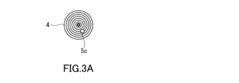
- FIG. 3A is a cross-sectional view showing the winding state of the electrode group and the position of the positive electrode lead portion.
- FIG. 3B is an enlarged cross-sectional view schematically showing a portion of the positive electrode lead portion shown in FIG. 3A.
- the area of the positive electrode active material layer is Also, the area of the negative electrode active material layer is increased. For example, in a state where a positive electrode and a negative electrode are overlapped with a separator interposed therebetween, if the positive electrode mixture layer surface protrudes from the outer edge of the negative electrode active material layer surface, lithium will precipitate on the negative electrode at the location where the positive electrode protrudes.
- the area of the negative electrode active material layer is larger than the area of the positive electrode active material layer, in the electrode group, there is a region where the negative electrode active material layer faces the positive electrode active material layer, and a region where the negative electrode active material layer faces the positive electrode active material layer.
- a step corresponding to the thickness of the positive electrode is created between the regions that are not facing each other.
- the expansion of the Si-based active material is large, and stress is concentrated at the above-mentioned step portion. If foreign matter were to enter such a stepped portion and penetrate the separator, an internal short circuit would occur.
- contaminating foreign substances are, for example, those derived from components of manufacturing equipment (e.g., metal parts or metal jigs) that occur very rarely due to wear or the like during the manufacturing process (e.g., metal components). It is possible that there is a foreign object. Also, in very rare cases, foreign matter may have adhered to battery parts.
- an insulating tape is placed on the part facing the positive electrode of the part where the negative electrode core is exposed from the end of the part coated with the negative electrode active material of the negative electrode. It is pasted. That is, the insulating tape is placed at a position corresponding to the stepped portion.
- the present inventors have newly discovered that even if an insulating tape is placed in the stepped portion, the following problem occurs due to expansion of the negative electrode. Due to the expansion of the negative electrode, misalignment between the positive electrode and the negative electrode is likely to occur in the stepped portion.
- a composite material tape serving as an electrode heat insulating plate is arranged at a position corresponding to the stepped portion in the electrode group having a wound structure.
- the composite material tape can prevent the foreign matter from causing internal damage. It is difficult to prevent short circuits.
- the present inventors have conducted intensive research to reduce the possibility of internal short circuits caused by foreign matter mixed into the electrode group in the stress-concentrated portion of the electrode group having a wound structure, and The present inventors have arrived at the nonaqueous electrolyte secondary battery of the present disclosure, which can suppress metal deposition at the negative electrode.
- the non-aqueous electrolyte secondary battery of the present disclosure includes an electrode group including a positive electrode, a negative electrode, and a separator disposed between the positive electrode and the negative electrode, and has a wound structure, and a non-aqueous electrolyte.
- the negative electrode includes a negative electrode current collector and a negative electrode active material layer.
- the electrode group satisfies at least one configuration selected from the group consisting of the following (A) and (B): (A) At least one end in the longitudinal direction of the negative electrode, the electrode group is configured to conduct the negative electrode current collection from the surface of the negative electrode active material layer facing the separator via the end surface of the negative electrode active material layer.
- the electrode group further includes an insulating protective tape adhered to a surface of the negative electrode active material layer facing the separator in a region of the negative electrode facing the positive electrode lead portion of the positive electrode.
- the base material of the above-mentioned protective tape is a microporous resin film having a compressive deformation rate of 30% or more and 50% or less when a load of 50 kg/cm 2 is applied.
- the protective tape having the above-mentioned characteristics includes at least one area selected from the group consisting of the area specified in (A) above and the area specified in (B) above. It is set up in two areas. The area specified in (A) above and the area specified in (B) above are areas where stress in the electrode group is likely to be concentrated. With this configuration, the non-aqueous electrolyte secondary battery of the present disclosure reduces the possibility of internal short circuits caused by foreign matter mixed into the electrode group in the stress-concentrated portion of the electrode group, and suppresses metal deposition at the negative electrode. I can do it.
- FIG. 1 is a cross-sectional view of a non-aqueous electrolyte secondary battery according to Embodiment 1 of the present disclosure.
- a lithium ion secondary battery will be described as an example of the nonaqueous electrolyte secondary battery of the present disclosure.
- the lithium ion secondary battery 100 includes a container 1 and an electrode group 4.
- An electrode group 4 is housed in the container 1 .
- the electrode group 4 has a wound structure.
- the electrode group 4 includes a positive electrode 5, a negative electrode 6, and a pair of separators 7. That is, the electrode group 4 is formed by overlapping a positive electrode 5 and a negative electrode 6 with a separator 7 disposed between the positive electrode 5 and the negative electrode 6, and winding them in a spiral shape.
- the electrode group 4 is impregnated with an electrolytic solution that is a non-aqueous electrolyte.
- the opening of the container 1 is closed with a sealing plate 2.
- the positive electrode 5 has a positive electrode current collector 5a and a positive electrode active material layer 5b.
- the negative electrode 6 includes a negative electrode current collector 6a and a negative electrode active material layer 6b.
- One end of a negative electrode lead 6c is connected to the negative electrode 6.
- the other end of the negative electrode lead 6c is connected to the bottom surface of the container 1.
- Insulating rings 8 are arranged on the upper and lower surfaces of the electrode group 4, respectively.
- the container 1 has negative polarity
- the sealing plate 2 has positive polarity
- the container 1 may have positive polarity and the sealing plate 2 may have negative polarity.
- FIG. 2A is a partially expanded cross-sectional view showing the winding state of the electrode group 4.
- FIG. 2B is an enlarged cross-sectional view of the outer peripheral end 10 in the longitudinal direction of the electrode group 4 shown in FIG. 2A. Note that the longitudinal direction of the electrode group 4 corresponds to a direction along the winding direction of the electrode group 4. Note that the same applies to the longitudinal direction of the negative electrode 6 below.
- the electrode group 4 includes a negative electrode active material layer 6b at at least one end 10 in the longitudinal direction of the negative electrode 6.
- a protective tape 9 having an insulating property is further attached to a region 60 extending from a surface 61 facing the separator 7 to an exposed portion 63 of the negative electrode current collector 6a via an end surface 62 of the negative electrode active material layer 6b.
- a configuration example is shown in which a protective tape 9 is provided at an end corresponding to the outer peripheral side of the wound electrode group 4 as at least one end in the longitudinal direction of the negative electrode 6.
- a protective tape 9 may be provided at the inner peripheral end of the negative electrode 6 in the longitudinal direction.
- the protective tape 9 includes a base material.
- the base material of the protective tape is a microporous resin film having a compressive deformation rate of 30% or more and 50% or less when a load of 50 kg/cm 2 is applied.
- the compressive deformation rate of the base material of the protective tape 9 is determined by, for example, the material of the base material, the porosity of the base material, the pore size distribution of the base material, the thickness of the base material, the molecular weight of the base material, the mechanical properties of the base material ( For example, by adjusting the compressive deformation yield stress, etc., it is possible to achieve a range of 30% or more and 50% or less.
- the negative electrode active material layer 6b In the lithium ion secondary battery 100 in this embodiment, for example, in order to cause Li ions desorbed from the positive electrode active material of the positive electrode 5 to react with the negative electrode active material or to be inserted into the negative electrode active material, the negative electrode active material layer 6b
- the area of the positive electrode active material layer 5b is designed to be larger than that of the positive electrode active material layer 5b. Therefore, the end portion 10 of the electrode group 4 has a region where the negative electrode active material layer 6b faces the positive electrode active material layer 5b and a region where the negative electrode active material layer 6b does not face the positive electrode active material layer 5b. In between, a step corresponding to the thickness of the positive electrode 5 occurs.
- region 60 extending from the surface 61 of the negative electrode active material layer 6b facing the separator 7 to the exposed portion 63 of the negative electrode current collector 6a via the end surface 62 of the negative electrode active material layer 6b becomes the above-mentioned stepped portion. . Therefore, region 60 corresponds to a portion of the electrode group where stress is concentrated.
- a protective tape 9 including a base material having a compressive deformation rate of 30% or more and 50% or less is arranged.
- the lithium ion secondary battery 100 of the present embodiment can reduce the possibility of an internal short circuit caused by foreign matter mixed into the electrode group 4 in the portion of the electrode group 4 where stress is concentrated.
- the base material of the protective tape 9 is a resin-based microporous membrane. Therefore, the protective tape 9 has ion permeability. Since the protective tape 9 does not inhibit the movement of lithium ions to the negative electrode active material layer 6b, it is possible to suppress the occurrence of lithium precipitation in the portion of the negative electrode 6 to which the protective tape 9 is adhered and in the vicinity thereof.
- the protective tape 9 may be formed only from the above base material. In this case, the protective tape 9 can be adhered to the region 60 of the negative electrode 6 by heating and pressing. Furthermore, as another example, the protective tape 9 may further include an adhesive layer provided on at least one surface of the base material. This configuration makes it easier to install the protective tape.
- the adhesive layer may be provided on one side or both sides of the base material. For example, an adhesive that swells in an electrolytic solution and has ion permeability is selected as the adhesive included in the adhesive layer.
- an acrylic adhesive, a rubber adhesive, and a silicone adhesive can be used as the adhesive contained in the adhesive layer.
- the resin-based microporous membrane may be, for example, a microporous membrane made of polyolefin resin.
- a microporous membrane made of polyolefin resin As a base material, the protective tape 9 can have good ion permeability. Therefore, the occurrence of lithium precipitation in the negative electrode 6 can be suppressed more reliably. Furthermore, with a microporous membrane made of polyolefin resin, it is easy to achieve a compressive deformation rate of 30% or more and 50% or less.
- the resin-based microporous membrane may contain at least one selected from the group consisting of polyphenylene sulfide (PPS) and polyimide (PI).
- PPS polyphenylene sulfide
- PI polyimide
- the protective tape 9 may further include a porous layer containing an inorganic material, disposed on the base material.
- a porous layer containing an inorganic material By providing the porous layer containing an inorganic material on the base material, the heat resistance of the protective tape 9 is improved. Thereby, it is possible to suppress the expansion of the internal short-circuit location due to heat generation.
- the thickness of the protective tape 9 is, for example, 10 ⁇ m or more and 100 ⁇ m or less. With this configuration, it is possible to more reliably suppress the occurrence of lithium precipitation in the negative electrode 6 and to further reduce the possibility that an internal short circuit due to foreign matter will occur.
- the compressive deformation rate of the base material of the protective tape 9 may be greater than the compressive deformation rate of the separator 7 when a load of 50 kg/cm 2 is applied.
- a microporous membrane having an average pore diameter of about 0.01 ⁇ m to 1 ⁇ m can be used as the resin-based microporous membrane. This can reduce the possibility that an internal short circuit will occur due to foreign matter.
- the average pore diameter of the microporous membrane is the median diameter determined from the pore diameter distribution measured by a mercury porosimeter. The median diameter means the pore diameter when the cumulative volume in the volume-based pore distribution is equal to 50%.
- a sheet or film made of a metal material such as aluminum, stainless steel, titanium, or an alloy thereof can be used as the positive electrode current collector 5a.
- Aluminum and its alloys are suitable as materials for the positive electrode current collector 5a because they are inexpensive and easy to form into thin films.
- the sheet or film may be porous or non-porous.
- Metal foil, metal mesh, etc. are used as the sheet or film.
- a carbon material such as carbon may be coated on the surface of the positive electrode current collector 5a as a conductive auxiliary material.
- the positive electrode active material contained in the positive electrode active material layer 5b is not particularly limited as long as it is a material that can reversibly insert and release lithium ions.
- a lithium-containing transition metal compound can be used as the positive electrode active material.
- the lithium-containing transition metal compound include composite oxides containing lithium and at least one element selected from the group consisting of cobalt, manganese, nickel, chromium, iron, and vanadium.
- LiCoO 2 , LiMnO 2 , LiNiO 2 , LiNix M (1-x) O 2 (M includes at least one selected from the group consisting of Co, Mn, Fe, Mg, Ti and Al, x satisfies 0.3 ⁇ x ⁇ 0.95), LiCrO 2 , ⁇ LiFeO 2 , LiVO 2 and the like.
- the positive electrode active material layer 5b may contain other materials such as a conductive aid, an ion conductor, and a binder.
- the conductive aid and the ionic conductor are used to reduce the resistance of the positive electrode 5.
- the conductive aid include carbon materials, conductive polymer compounds, and the like.
- carbon materials include carbon black, graphite, acetylene black, carbon nanotubes, carbon nanofibers, graphene, fullerene, and graphite oxide.
- the conductive polymer compound include polyaniline, polypyrrole, polythiophene, and the like.
- Examples of the ion conductor include gel electrolytes, organic solid electrolytes, and inorganic solid electrolytes.
- the gel electrolytes include polymethyl methacrylate and polymethyl methacrylate.
- the organic solid electrolyte include polyethylene oxide.
- the inorganic solid electrolyte include Li 7 La 3 Zr 2 O 12 and the like.
- the binder is used to improve the binding properties of the materials constituting the positive electrode 5.
- a binder polyvinylidene fluoride, vinylidene fluoride-hexafluoropropylene copolymer, vinylidene fluoride-tetrafluoroethylene copolymer, polytetrafluoroethylene, carboxymethylcellulose, polyacrylic acid, styrene-butadiene copolymer rubber, polypropylene Polymeric materials such as , polyethylene, polyimide, etc. may be used.
- a sheet or film made of a metal material such as stainless steel, nickel, copper, or an alloy thereof can be used as the negative electrode current collector 6a.
- the sheet or film may be porous or non-porous.
- Metal foil, metal mesh, etc. are used as the sheet or film.
- a carbon material such as carbon may be coated on the surface of the negative electrode current collector 6a as a conductive auxiliary material.
- the negative electrode active material contained in the negative electrode active material layer 6b is not particularly limited as long as it is a material that can reversibly insert and release lithium ions.
- a carbon material containing graphite having a graphite-type crystal structure can be used as the negative electrode active material.
- Examples of such carbon materials include natural graphite, spherical or fibrous artificial graphite, non-graphitizable carbon (hard carbon), easily graphitizable carbon (soft carbon), and the like.
- materials other than carbon materials include lithium titanate.
- high-capacity materials such as silicon, tin, silicon alloys, tin alloys, silicon oxide, silicon nitride, tin oxide, and composite materials of silicon and carbon may also be used as negative electrode active materials. It can be suitably used as
- the negative electrode active material layer 6b may contain at least one selected from the group consisting of graphite and silicon as a negative electrode active material.
- the negative electrode active material layer 6b may include only graphite as the negative electrode active material. Graphite is recommended because it does not deteriorate easily even after repeated charging and discharging at deep depths. Carbon materials other than graphite may be used as the negative electrode active material. Since silicon exhibits a larger capacity than graphite, it is advantageous for increasing the capacity of the lithium ion secondary battery 100.
- the negative electrode active material layer 6b may contain a Si-based active material as a negative electrode active material.
- the Si-based active material is an active material containing Si element. Examples include simple Si, Si alloys, Si-containing compounds, Si-containing compositions, and composites of Si and carbon. Examples of Si-containing compositions include those in which Si particles are dispersed in a lithium silicate phase containing Li 2 Si 2 O 5 as a main component (Li x Si y O z (x>0, y>0, z> 0))).
- a negative electrode containing a Si-based active material as a negative electrode active material stress tends to be concentrated at the step portion because the Si-based active material expands greatly, and internal short circuits due to mixed foreign matter are also likely to occur.
- metal precipitation on the negative electrode 6 can be suppressed and the possibility of internal short circuit can be reduced. That is, the configuration of the present disclosure can effectively reduce the possibility of internal short circuits caused by foreign matter even when the negative electrode is likely to expand.
- the negative electrode active material layer 6b may contain a conductive aid, an ion conductor, a binder, and the like.
- the same materials that can be used for the positive electrode active material layer 5b can be used for the negative electrode active material layer 6b as the conductive aid, the ion conductor, and the binder.
- the separator 7 has lithium ion permeability.
- the material of the separator 7 is not particularly limited as long as the passage of lithium ions is allowed.
- the material of the separator 7 may be at least one selected from the group consisting of a gel electrolyte, an ion exchange resin membrane, a semipermeable membrane, and a porous membrane. If the separator 7 is made of these materials, the safety of the lithium ion secondary battery 100 can be sufficiently ensured.
- the gel electrolyte include gel electrolytes containing fluororesins such as PVdF.
- ion exchange resin membranes include cation exchange membranes and anion exchange membranes.
- the porous membrane include a porous membrane made of polyolefin resin and a porous membrane containing glass paper obtained by weaving glass fibers into a nonwoven fabric.
- the electrolytic solution is a non-aqueous electrolyte with which the positive electrode 5, negative electrode 6, and separator 7 are impregnated.
- the electrolyte may fill the interior space of the container 1. Lithium ions can move back and forth between the positive electrode 5 and the negative electrode 6 due to the action of the electrolyte.
- the electrolytic solution includes a nonaqueous solvent and a lithium salt.
- nonaqueous solvent examples include a cyclic carbonate solvent, a chain carbonate solvent, a cyclic ether solvent, a chain ether solvent, a cyclic ester solvent, a chain ester solvent, or a fluorine solvent.
- cyclic carbonate solvents are ethylene carbonate, propylene carbonate, or butylene carbonate.
- linear carbonate solvents are dimethyl carbonate, ethylmethyl carbonate, or diethyl carbonate.
- cyclic ether solvents are tetrahydrofuran, 1,4-dioxane or 1,3-dioxolane.
- An example of a linear ether solvent is 1,2-dimethoxyethane or 1,2-diethoxyethane.
- An example of a cyclic ester solvent is ⁇ -butyrolactone.
- An example of a linear ester solvent is methyl acetate.
- fluorine solvents are fluoroethylene carbonate, methyl fluoropropionate, fluorobenzene, fluoroethylmethyl carbonate, or fluorodimethylene carbonate.
- One type of nonaqueous solvent selected from these may be used alone. Alternatively, a mixture of two or more nonaqueous solvents selected from these may be used.
- lithium salts include lithium hexafluorophosphate (LiPF 6 ), lithium tetrafluoroborate (LiBF 4 ), lithium perchlorate (LiClO 4 ), lithium bis(fluorosulfonyl)imide (LiFSI), and lithium bis( Examples include trifluoromethanesulfonyl)imide (LiTFSI), lithium bisperfluoroethylsulfonylimide (LiN(SO 2 C 2 F 5 ) 2 ), LiAsF 6 , LiCF 3 SO 3 , and lithium difluoro(oxalato)borate.
- LiPF 6 lithium hexafluorophosphate
- LiBF 4 lithium tetrafluoroborate
- LiClO 4 lithium perchlorate
- LiFSI lithium bis(fluorosulfonyl)imide
- lithium bis( Examples include trifluoromethanesulfonyl)imide (LiTFSI), lithium bisper
- the container 1 is, for example, a container made of metal such as aluminum or stainless steel.
- the container 1 may have a cylindrical shape or a rectangular tube shape.
- the electrode group 4 may be wound in a cylindrical shape or in an elliptical shape.
- the shape of the lithium ion secondary battery 100 is not particularly limited.
- the lithium ion secondary battery 100 may have various shapes such as a cylindrical shape and a prismatic shape.
- the electrode group 4 is produced. Specifically, a positive electrode 5, a negative electrode 6, a separator 7, and a protective tape 9 are each prepared. A protective tape 9 is adhered to a predetermined position of the negative electrode 6. For example, as shown in FIG. 2B, the protective tape 9 is applied to the negative electrode from the surface of the negative electrode active material layer facing the separator at the outer peripheral end in the longitudinal direction of the negative electrode 6 via the end surface of the negative electrode active material layer. When the protective tape 9 is placed in a position that extends to the exposed portion of the current collector, the protective tape 9 is adhered to that position. Next, the positive electrode 5, the negative electrode 6, and a pair of separators 7 are stacked and wound so that a spirally wound electrode group 4 is formed. Thereby, the electrode group 4 is obtained.
- the positive electrode 5 can be produced by applying a positive electrode composite material to one or both sides of the positive electrode current collector 5a, drying, and rolling it.
- the positive electrode 5 has a thickness of, for example, 30 ⁇ m to 200 ⁇ m, and is preferably highly flexible.
- the positive electrode composite material is obtained by kneading and uniformly dispersing materials such as a positive electrode active material, a binder, and a conductive material using a dispersion medium.
- the method of applying the positive electrode mixture to the positive electrode current collector 5a is not particularly limited.
- the positive electrode mixture in slurry form can be applied to the positive electrode current collector 5a using a slit die coater, reverse roll coater, lip coater, blade coater, knife coater, gravure coater, dip coater, or the like.
- the applied positive electrode composite material may be dried naturally or may be dried using a drying device.
- the positive electrode 5 After drying, the positive electrode 5 is rolled so that the positive electrode active material layer 5b has a predetermined thickness. Rolling may be performed multiple times using a roll press machine, or may be performed multiple times while changing the pressing pressure of the roll press machine. After rolling, a positive electrode lead 5c for power extraction is welded to the positive electrode current collector 5a.
- the negative electrode 6 can be produced by applying a negative electrode composite material to one or both sides of the negative electrode current collector 6a, drying, and rolling it.
- the negative electrode 6 has a thickness of, for example, 30 ⁇ m to 210 ⁇ m, and is preferably highly flexible.
- the negative electrode composite material is obtained by kneading and uniformly dispersing materials such as a negative electrode active material, a binder, and a conductive material using a dispersion medium.
- a dry method may be adopted instead of the above-mentioned wet method.
- the dry film forming method include a vapor deposition method, a sputtering method, and a CVD method (chemical vapor deposition method). All of these methods can be performed in vacuum. From the viewpoint of efficiently forming the negative electrode active material layer 6b, a vapor deposition method is preferable.
- the vapor deposition method either electron beam vapor deposition or resistance heating vapor deposition can be adopted.
- oxides and/or nitrides can be used as the evaporation material.
- reactive vapor deposition may be performed.
- the electrode group 4 is placed in the container 1, and the electrolyte is further poured into the container 1. Finally, the container 1 is sealed.
- the lithium ion secondary battery 100 shown in FIG. 1 is obtained.
- Embodiment 2 The lithium ion secondary battery which is a non-aqueous electrolyte secondary battery according to Embodiment 2 of the present disclosure is different from the lithium ion secondary battery according to Embodiment 1 in the position where the protective tape is provided, but the other configuration is Everything is the same as the lithium ion secondary battery according to the first embodiment. Therefore, in this embodiment, only the position where the protective tape is provided will be described.
- FIG. 3A is a cross-sectional view showing the winding state of the electrode group 4 and the position of the positive electrode lead portion.
- FIG. 3B is an enlarged cross-sectional view schematically showing a portion of the positive electrode lead portion shown in FIG. 3A.
- the electrode group 4 includes a negative electrode active material layer 6b in a region of the negative electrode 6 that faces the positive electrode lead portion of the positive electrode 5. It further includes an insulating protective tape 19 adhered to the surface facing the separator 7 .
- the positive electrode lead portion refers to a portion of the positive electrode 5 including the portion where the positive electrode lead 5c is connected and the vicinity thereof. Note that the positive electrode lead 5c is protected by a lead protection tape 5d.
- the protective tape 19 may have similar characteristics and structure to the protective tape 9 described in the first embodiment. That is, the base material of the protective tape 19 is a microporous resin film whose compressive deformation rate is 30% or more and 50% or less when a load of 50 kg/cm 2 is applied.
- the positive electrode lead portion includes a portion where the positive electrode active material layer 5b is not provided. In this way, the positive electrode lead portion includes a region where the negative electrode active material layer 6b faces the positive electrode active material layer 5b and a region where the negative electrode active material layer 6b does not face the positive electrode active material layer 5b, and A difference in level occurs between both areas in group 4.
- the positive electrode lead portion becomes a stepped portion, and corresponds to a portion where stress of the electrode group 4 is concentrated.
- a protective tape 19 including a base material having a compressive deformation rate of 30% or more and 50% or less is disposed in a region of the negative electrode 6 facing the positive electrode lead portion of the positive electrode 5.
- the base material of the protective tape 19 is a resin-based microporous membrane, similar to the protective tape 9. Therefore, the protective tape 19 has ion permeability. Since the protective tape 19 does not inhibit the movement of lithium ions to the negative electrode active material layer 6b, it is possible to suppress the occurrence of lithium precipitation in and around the portion of the negative electrode 6 to which the protective tape 19 is adhered.
- the lithium ion secondary battery of this embodiment may further include a protective tape 9 in addition to the protective tape 19. That is, the protective tape 9 of Embodiment 1 may be further applied to the lithium ion secondary battery of Embodiment 2. In this case, the possibility of an internal short circuit caused by foreign matter mixed into the electrode group 4 can be further reduced.
- the protective tape 19 and the protective tape 9 may be made of the same material and structure, or may be made of different materials and structure.
- a non-aqueous electrolyte secondary battery comprising:
- the negative electrode includes a negative electrode current collector and a negative electrode active material layer,
- the electrode group satisfies at least one configuration selected from the group consisting of the following (A) and (B): (A) At least one end in the longitudinal direction of the negative electrode, the electrode group is configured to conduct the negative electrode current collection from the surface of the negative electrode active material layer facing the separator via the end surface of the negative electrode active material layer.
- the electrode group further includes an insulating protective tape adhered to a surface of the negative electrode active material layer facing the separator in a region of the negative electrode facing the positive electrode lead portion of the positive electrode.
- the base material of the protective tape is a resin microporous membrane having a compressive deformation rate of 30% or more and 50% or less when a load of 50 kg/cm 2 is applied.
- the non-aqueous electrolyte secondary battery of Technology 1 reduces the possibility of internal short circuits caused by foreign matter mixed into the electrode group in the stress-concentrated portion of the electrode group, and suppresses metal deposition on the negative electrode. I can do it.
- Example 1 [Compressive deformation rate of base material of protective tape]
- the microporous membrane that is the base material of the protective tape was produced by the method described below.
- High-density polyethylene with a viscosity average molecular weight of 400,000 and liquid paraffin (kinematic viscosity 7.59 x 10 -5 m 2 /s at 37.8°C) were mixed at a mass ratio of 4:6 and melted and kneaded at 200°C. did.
- the obtained kneaded product was extruded into a sheet having a thickness of 1 mm.
- This sheet was stretched 7 ⁇ 7 times using a simultaneous biaxial stretching machine, and then immersed in methylene chloride to extract and remove liquid paraffin to produce a microporous membrane. Furthermore, this microporous membrane was stretched in the transverse direction using a tenter stretching machine. By setting the stretching ratio at this time to 1.3, a microporous membrane with high porosity and good compressibility was obtained.
- the compressive deformation rate of this base material was determined as follows using a testing machine that complies with JIS K 7181. As measurement samples, 10 sheets of 3 cm x 3 cm were cut from the base material, and these 10 sheets were stacked in the thickness direction and placed on a compression jig with a diameter of 15 mm. Next, the measurement sample was compressed in the thickness direction at a speed of 1 mm/min, and the amount of thickness change when the compressive stress was 50 kg/cm 2 was measured to determine the compressive deformation rate. The result was 30%, as shown in Table 1.
- the negative electrode was produced as follows.
- As the graphite spherical natural graphite coated with carbon was used.
- As the Si-based active material a Si-containing composition (Si particles dispersed in a lithium silicate phase containing Li 2 Si 2 O 5 as a main component (Li x Si y O z composition)) was used. These graphite and Si-based active material were mixed at a mass ratio of 80:20 (graphite:Si-based active material).
- Carboxymethylcellulose (CMC), styrene-butadiene rubber (SBR), and polyacrylic acid (PAA) were added as binders to the resulting mixture to prepare an aqueous slurry.
- the resulting aqueous slurry was applied to both sides of a 10 ⁇ m thick copper foil and dried to obtain a sheet-like product. Thereafter, the obtained sheet-like material was rolled to a thickness of 120 ⁇ m, and this was used as a negative electrode.
- a protective tape was attached to the above negative electrode.
- the protective tape was produced by forming an adhesive layer on one main surface of the base material (i.e., microporous membrane) of the protective tape produced by the method described above. This protective tape was attached to the negative electrode using an adhesive layer.
- the adhesive layer was made of acrylic adhesive.
- One metal particle with a diameter of about 50 ⁇ m is placed on the protective tape attached to the negative electrode as described above, and a load of 50 kg/cm 2 is applied to that part to test the insulation between the metal particle and the negative electrode. confirmed.
- spherical nickel particles were used as the metal particles.
- the load was released, and it was confirmed whether or not metal particles were buried in the base material of the protective tape.
- the insulation between the metal particles and the negative electrode was confirmed by pressing the metal particles with a metal indenter and measuring the resistance between the indenter and the negative electrode with a resistance meter to determine whether there was continuity.
- the unevenness around the metal particles was measured using a laser microscope, and a state where 50% or more of the volume of the metal particles was embedded in the base material was determined to be buried. .
- the protective tape was compressed by applying a load of 50 kg/cm 2 in the thickness direction, and the protective tape was attached to a predetermined position on the negative electrode.
- the predetermined position means, when an electrode group having a wound structure is formed, the negative electrode active material layer is This is the area that extends through the end face of the negative electrode current collector to the exposed part of the negative electrode current collector.
- a lithium transition metal composite oxide represented by LiCo 1/3 Mn 1/3 Ni 1/3 O 2 was used as the positive electrode active material.
- a positive electrode mixture slurry was prepared by mixing 98 parts by mass of positive electrode active material, 1 part by mass of acetylene black, and 1 part by mass of polyvinylidene fluoride, and using N-methyl-2-pyrrolidone (NMP) as a dispersion medium. was prepared.
- NMP N-methyl-2-pyrrolidone
- the positive electrode mixture slurry is applied to both sides of a positive electrode core made of aluminum foil, the coating is dried and compressed, and then cut into a predetermined electrode size, so that a positive electrode mixture layer is formed on both sides of the positive electrode core.
- a positive electrode was produced. Note that an exposed portion in which the surface of the core body was exposed was provided at the longitudinal center of the positive electrode, and a positive electrode lead was welded to the exposed portion.
- LiPF 6 is dissolved at a concentration of 1 mol/L in a mixed solvent of ethylene carbonate (EC) and ethyl methyl carbonate (EMC) at a mass ratio of 1:3 (EC:EMC) to form a non-aqueous electrolyte.
- An electrolytic solution was prepared as follows.
- the prepared test cell was subjected to charge/discharge cycles (4.2V-2.5V, charging 0.5C/discharging 0.7C), and after 100 cycles, the test cell was disassembled and the lithium deposited on the negative electrode where the protective tape was attached was removed. I checked to see if it was there. The results are shown in Table 1.
- Example 2 A battery was prepared and various tests were performed in the same manner as in Example 1, except that the protective tape used was different.
- the protective tape used in Example 2 was produced in the same manner as in Example 1, except that the stretching ratio of the tenter stretching machine was set to 1.4 in producing the base material.
- the test results for the compressive deformation rate of the base material of the masking tape were 40%, as shown in Table 1.
- Example 3 A battery was prepared and various tests were performed in the same manner as in Example 1, except that the protective tape used was different.
- the protective tape used in Example 3 was produced in the same manner as in Example 1, except that the stretching ratio of the tenter stretching machine was set to 1.5 in producing the base material.
- the test results for the compressive deformation rate of the base material of the protective tape were 50%, as shown in Table 1.
- Comparative example 1 A battery was prepared and various tests were performed in the same manner as in Example 1, except that the protective tape used was different.
- the protective tape used in Comparative Example 1 was produced in the same manner as in Example 1, except that the stretching ratio of the tenter stretching machine was set to 1.2 in producing the base material.
- the test results for the compressive deformation rate of the base material of the protective tape were 20%, as shown in Table 1.
- Comparative example 2 A battery was prepared and various tests were performed in the same manner as in Example 1, except that the protective tape used was different.
- the protective tape used in Comparative Example 2 was produced in the same manner as in Example 1, except that the stretching ratio of the tenter stretching machine was set to 1.6 in producing the base material.
- the test result of the compressive deformation rate of the base material of the protective tape was 60%, as shown in Table 1.
- Comparative Example 1 in which a protective tape whose base material had a compressive deformation rate of 20% was used, metal particles were not buried in the base material of the protective tape. Therefore, it is considered that the protective tape of Comparative Example 1 cannot significantly reduce the possibility of internal short circuit caused by foreign matter mixed into the electrode group. Furthermore, in Comparative Example 2 in which a protective tape whose base material had a compressive deformation rate of 60% was used, lithium was precipitated after 100 charge/discharge cycles. This is considered to be because the protective tape of Comparative Example 2 had a high compression deformation rate, so the pores were crushed by compression during production of the electrode group, resulting in low ion permeability.
- a protective tape containing a base material that is a resin-based microporous film with a compressive deformation rate of 30% or more and 50% or less when a load of 50 kg/cm 2 is applied has a stress concentration on the electrode group. It was confirmed that the possibility of internal short circuit caused by foreign matter mixed into the electrode group can be reduced by installing the electrode group in the area where the negative electrode is exposed, and metal precipitation on the negative electrode can be suppressed.
- the technology of the present disclosure is useful for lithium ion secondary batteries.
Landscapes
- Chemical & Material Sciences (AREA)
- Chemical Kinetics & Catalysis (AREA)
- Electrochemistry (AREA)
- General Chemical & Material Sciences (AREA)
- Engineering & Computer Science (AREA)
- Manufacturing & Machinery (AREA)
- Materials Engineering (AREA)
- Inorganic Chemistry (AREA)
- Secondary Cells (AREA)
- Battery Electrode And Active Subsutance (AREA)
Priority Applications (4)
| Application Number | Priority Date | Filing Date | Title |
|---|---|---|---|
| CN202380053329.1A CN119522500A (zh) | 2022-07-27 | 2023-06-29 | 非水电解质二次电池 |
| US18/994,477 US20260038870A1 (en) | 2022-07-27 | 2023-06-29 | Nonaqueous electrolyte secondary battery |
| EP23846118.0A EP4564515A4 (en) | 2022-07-27 | 2023-06-29 | SECONDARY BATTERY WITH NON-AQUEOUS ELECTROLYTE |
| JP2024536879A JPWO2024024385A1 (https=) | 2022-07-27 | 2023-06-29 |
Applications Claiming Priority (2)
| Application Number | Priority Date | Filing Date | Title |
|---|---|---|---|
| JP2022119832 | 2022-07-27 | ||
| JP2022-119832 | 2022-07-27 |
Publications (1)
| Publication Number | Publication Date |
|---|---|
| WO2024024385A1 true WO2024024385A1 (ja) | 2024-02-01 |
Family
ID=89706034
Family Applications (1)
| Application Number | Title | Priority Date | Filing Date |
|---|---|---|---|
| PCT/JP2023/024249 Ceased WO2024024385A1 (ja) | 2022-07-27 | 2023-06-29 | 非水電解質二次電池 |
Country Status (5)
| Country | Link |
|---|---|
| US (1) | US20260038870A1 (https=) |
| EP (1) | EP4564515A4 (https=) |
| JP (1) | JPWO2024024385A1 (https=) |
| CN (1) | CN119522500A (https=) |
| WO (1) | WO2024024385A1 (https=) |
Families Citing this family (1)
| Publication number | Priority date | Publication date | Assignee | Title |
|---|---|---|---|---|
| CN218827324U (zh) * | 2022-10-21 | 2023-04-07 | 宁德时代新能源科技股份有限公司 | 电极组件、电池单体、电池及用电装置 |
Citations (6)
| Publication number | Priority date | Publication date | Assignee | Title |
|---|---|---|---|---|
| JP4245429B2 (ja) | 2003-08-11 | 2009-03-25 | 三洋電機株式会社 | 渦巻状電極群を備えた電池 |
| JP4878800B2 (ja) | 2004-09-22 | 2012-02-15 | 三星エスディアイ株式会社 | リチウム二次電池 |
| JP2017216160A (ja) * | 2016-05-31 | 2017-12-07 | パナソニックIpマネジメント株式会社 | 非水電解質二次電池 |
| WO2018180748A1 (ja) * | 2017-03-28 | 2018-10-04 | 三洋電機株式会社 | 非水電解質二次電池 |
| WO2019049479A1 (ja) * | 2017-09-11 | 2019-03-14 | パナソニックIpマネジメント株式会社 | 二次電池 |
| WO2021020151A1 (ja) * | 2019-07-31 | 2021-02-04 | 株式会社村田製作所 | 二次電池 |
Family Cites Families (2)
| Publication number | Priority date | Publication date | Assignee | Title |
|---|---|---|---|---|
| JP4382557B2 (ja) * | 2004-03-30 | 2009-12-16 | 日立マクセル株式会社 | 非水二次電池 |
| JP4586820B2 (ja) * | 2007-05-07 | 2010-11-24 | ソニー株式会社 | 巻回型非水電解質二次電池 |
-
2023
- 2023-06-29 WO PCT/JP2023/024249 patent/WO2024024385A1/ja not_active Ceased
- 2023-06-29 EP EP23846118.0A patent/EP4564515A4/en active Pending
- 2023-06-29 JP JP2024536879A patent/JPWO2024024385A1/ja active Pending
- 2023-06-29 US US18/994,477 patent/US20260038870A1/en active Pending
- 2023-06-29 CN CN202380053329.1A patent/CN119522500A/zh active Pending
Patent Citations (6)
| Publication number | Priority date | Publication date | Assignee | Title |
|---|---|---|---|---|
| JP4245429B2 (ja) | 2003-08-11 | 2009-03-25 | 三洋電機株式会社 | 渦巻状電極群を備えた電池 |
| JP4878800B2 (ja) | 2004-09-22 | 2012-02-15 | 三星エスディアイ株式会社 | リチウム二次電池 |
| JP2017216160A (ja) * | 2016-05-31 | 2017-12-07 | パナソニックIpマネジメント株式会社 | 非水電解質二次電池 |
| WO2018180748A1 (ja) * | 2017-03-28 | 2018-10-04 | 三洋電機株式会社 | 非水電解質二次電池 |
| WO2019049479A1 (ja) * | 2017-09-11 | 2019-03-14 | パナソニックIpマネジメント株式会社 | 二次電池 |
| WO2021020151A1 (ja) * | 2019-07-31 | 2021-02-04 | 株式会社村田製作所 | 二次電池 |
Non-Patent Citations (1)
| Title |
|---|
| See also references of EP4564515A4 |
Also Published As
| Publication number | Publication date |
|---|---|
| EP4564515A1 (en) | 2025-06-04 |
| CN119522500A (zh) | 2025-02-25 |
| EP4564515A4 (en) | 2025-11-05 |
| US20260038870A1 (en) | 2026-02-05 |
| JPWO2024024385A1 (https=) | 2024-02-01 |
Similar Documents
| Publication | Publication Date | Title |
|---|---|---|
| CN110364667B (zh) | 多孔膜和锂离子电池 | |
| CN110137442B (zh) | 基于石墨的负电极活性材料、负电极和锂离子二次电池 | |
| CN108199035B (zh) | 锂二次电池 | |
| CN105576279B (zh) | 锂二次电池 | |
| CN101339980B (zh) | 隔膜、使用该隔膜的电池以及制造隔膜的方法 | |
| WO2014010526A1 (ja) | 非水電解質二次電池 | |
| EP2755260B1 (en) | Electric storage device and method for producing electric storage device | |
| KR20170057446A (ko) | 비수 전해질 이차 전지, 상기 비수 전해질 이차 전지에 사용되는 전극체, 및 상기 전극체의 제조방법 | |
| US20140011083A1 (en) | Electrode for non-aqueous electrolyte secondary batteries and non-aqueous electrolyte secondary battery including the same | |
| JP2019160553A (ja) | 電極及び蓄電素子 | |
| JPWO2002091514A1 (ja) | 非水電解質電池およびその製造方法 | |
| KR102209653B1 (ko) | 스웰링 현상이 개선된 음극 및 이를 포함하는 리튬이차전지 | |
| KR20210120686A (ko) | 음극의 제조방법 | |
| US20240055647A1 (en) | Lithium-containing electrochemical cells, electrochemical systems, and related methods | |
| WO2014007035A1 (ja) | 負極材、リチウムイオン二次電池用負極、リチウムイオン二次電池およびそれらの製造方法 | |
| CN111540869A (zh) | 锂离子二次电池用正极、锂离子二次电池用负极、锂离子二次电池及其制造方法 | |
| JP2024502645A (ja) | リチウム二次電池の活性化方法 | |
| WO2024024385A1 (ja) | 非水電解質二次電池 | |
| JP2007299580A (ja) | 非水電解質角型二次電池 | |
| WO2015046394A1 (ja) | 負極活物質、それを用いた負極、及びリチウムイオン二次電池 | |
| KR20220109699A (ko) | 이차전지의 제조방법 | |
| KR102898449B1 (ko) | 축전 장치의 전극의 제조 방법 및 축전 장치의 전극 | |
| KR20230065184A (ko) | 리튬 이차전지의 활성화 방법 및 활성화 장치 | |
| JP6128228B2 (ja) | 負極活物質、それを用いた負極、及びリチウムイオン二次電池 | |
| US20260081163A1 (en) | Non-aqueous electrolyte secondary battery |
Legal Events
| Date | Code | Title | Description |
|---|---|---|---|
| 121 | Ep: the epo has been informed by wipo that ep was designated in this application |
Ref document number: 23846118 Country of ref document: EP Kind code of ref document: A1 |
|
| WWE | Wipo information: entry into national phase |
Ref document number: 2024536879 Country of ref document: JP |
|
| WWE | Wipo information: entry into national phase |
Ref document number: 202380053329.1 Country of ref document: CN |
|
| WWE | Wipo information: entry into national phase |
Ref document number: 18994477 Country of ref document: US |
|
| WWE | Wipo information: entry into national phase |
Ref document number: 202547015910 Country of ref document: IN |
|
| WWP | Wipo information: published in national office |
Ref document number: 202380053329.1 Country of ref document: CN |
|
| WWE | Wipo information: entry into national phase |
Ref document number: 2023846118 Country of ref document: EP |
|
| NENP | Non-entry into the national phase |
Ref country code: DE |
|
| ENP | Entry into the national phase |
Ref document number: 2023846118 Country of ref document: EP Effective date: 20250227 |
|
| WWP | Wipo information: published in national office |
Ref document number: 202547015910 Country of ref document: IN |
|
| WWP | Wipo information: published in national office |
Ref document number: 2023846118 Country of ref document: EP |
|
| WWP | Wipo information: published in national office |
Ref document number: 18994477 Country of ref document: US |