WO2024019042A1 - 発泡ブロー成形体の製造方法、及び発泡ブロー成形体 - Google Patents
発泡ブロー成形体の製造方法、及び発泡ブロー成形体 Download PDFInfo
- Publication number
- WO2024019042A1 WO2024019042A1 PCT/JP2023/026245 JP2023026245W WO2024019042A1 WO 2024019042 A1 WO2024019042 A1 WO 2024019042A1 JP 2023026245 W JP2023026245 W JP 2023026245W WO 2024019042 A1 WO2024019042 A1 WO 2024019042A1
- Authority
- WO
- WIPO (PCT)
- Prior art keywords
- thermoplastic elastomer
- foam blow
- mass
- blow
- foam
- Prior art date
- Legal status (The legal status is an assumption and is not a legal conclusion. Google has not performed a legal analysis and makes no representation as to the accuracy of the status listed.)
- Ceased
Links
Classifications
-
- B—PERFORMING OPERATIONS; TRANSPORTING
- B29—WORKING OF PLASTICS; WORKING OF SUBSTANCES IN A PLASTIC STATE IN GENERAL
- B29C—SHAPING OR JOINING OF PLASTICS; SHAPING OF MATERIAL IN A PLASTIC STATE, NOT OTHERWISE PROVIDED FOR; AFTER-TREATMENT OF THE SHAPED PRODUCTS, e.g. REPAIRING
- B29C44/00—Shaping by internal pressure generated in the material, e.g. swelling or foaming ; Producing porous or cellular expanded plastics articles
-
- B—PERFORMING OPERATIONS; TRANSPORTING
- B29—WORKING OF PLASTICS; WORKING OF SUBSTANCES IN A PLASTIC STATE IN GENERAL
- B29C—SHAPING OR JOINING OF PLASTICS; SHAPING OF MATERIAL IN A PLASTIC STATE, NOT OTHERWISE PROVIDED FOR; AFTER-TREATMENT OF THE SHAPED PRODUCTS, e.g. REPAIRING
- B29C49/00—Blow-moulding, i.e. blowing a preform or parison to a desired shape within a mould; Apparatus therefor
- B29C49/02—Combined blow-moulding and manufacture of the preform or the parison
- B29C49/04—Extrusion blow-moulding
-
- C—CHEMISTRY; METALLURGY
- C08—ORGANIC MACROMOLECULAR COMPOUNDS; THEIR PREPARATION OR CHEMICAL WORKING-UP; COMPOSITIONS BASED THEREON
- C08J—WORKING-UP; GENERAL PROCESSES OF COMPOUNDING; AFTER-TREATMENT NOT COVERED BY SUBCLASSES C08B, C08C, C08F, C08G or C08H
- C08J9/00—Working-up of macromolecular substances to porous or cellular articles or materials; After-treatment thereof
- C08J9/04—Working-up of macromolecular substances to porous or cellular articles or materials; After-treatment thereof using blowing gases generated by a previously added blowing agent
Definitions
- the present invention relates to a method for producing a blow-molded foam and a blow-molded foam.
- the foam blow molded article is obtained by shaping a foam parison formed from a foamable resin melt containing a base resin.
- foam blow molded products hollow molded products using polyolefin resin as a base resin are used in various applications, such as air conditioning ducts in automobiles, etc., from the viewpoint of light weight and the like.
- the air conditioning duct may be referred to as a duct.
- Patent Document 1 and Patent Document 2 disclose a technique of adding an elastomer to a polypropylene resin.
- Patent Document 1 and Patent Document 2 had the problem of further improving the cold impact resistance and rigidity of the foam blow-molded product. Moreover, the techniques of Patent Document 1 and Patent Document 2 had a problem in improving the surface smoothness on the inner surface of the hollow portion of the hollow foam blow-molded article.
- surface smoothness on the inner surface of the hollow portion of the hollow foam blow-molded object will be simply referred to as surface smoothness.
- One of the objects of the present invention is to provide a method for producing a foam blow-molded article having excellent cold impact resistance, rigidity, and surface smoothness, and to provide a foam blow-molded article having excellent cold impact resistance, rigidity, and surface smoothness. may be provided.
- the gist of the present invention is the inventions shown in the following (1) to (5).
- a method for producing a foamed blow-molded article which includes the step of blow-molding a foamed parison formed by foaming a mixed resin of a polyolefin resin (A) and an olefinic thermoplastic elastomer (B),
- the polyolefin resin (A) consists of a branched homopolypropylene (a1) and a linear block polypropylene (a2), and the branched homopolypropylene (a1) and the linear block polypropylene (a2)
- the mass ratio [(a1):(a2)] is 50:50 to 93:7
- the olefin thermoplastic elastomer (B) is a hydrogenated product of a triblock copolymer consisting of a crystalline olefin polymer block and a conjugated diene compound polymer block,
- the amount of the olefin thermoplastic elastomer (B) based on 100 parts by mass of the polyolefin
- the melting point of the olefinic thermoplastic elastomer (B) is 80°C or more and 100°C or less, The method for producing a foam blow-molded article according to (1) above.
- the linear block polypropylene (a2) has a flexural modulus of 1000 MPa or more and 1500 MPa or less, The method for producing a foam blow-molded article according to (1) or (2) above.
- the melt flow rate (230° C., load 2.16 kg) of the olefin thermoplastic elastomer (B) is 1 g/10 min or more and 10 g/10 min or less, The method for producing a foam blow molded article according to any one of (1) to (3) above.
- the polyolefin resin (A) consists of a branched homopolypropylene (a1) and a linear block polypropylene (a2), and the branched homopolypropylene (a1) and the linear block polypropylene (a2)
- the mass ratio [(a1):(a2)] is 50:50 to 93:7
- the olefin thermoplastic elastomer (B) is a hydrogenated product of a triblock copolymer consisting of a crystalline olefin polymer block and a conjugated diene compound polymer block
- the foamed blow-molded article has a blending amount of the olefin thermoplastic elastomer (B) with respect to 100 parts by mass of the polyolefin resin (A) from 20 parts by mass to 40 parts by mass.
- the present invention may be the inventions described in the following (6) to (8).
- the melting point of the olefinic thermoplastic elastomer (B) is 80°C or more and 100°C or less, The foam blow-molded article according to (5) above.
- the linear block polypropylene (a2) has a flexural modulus of 1000 MPa or more and 1500 MPa or less, The foam blow molded article according to (5) or (6) above.
- the melt flow rate (230° C., load 2.16 kg) of the olefinic thermoplastic elastomer (B) is 1 g/10 min or more and 10 g/10 min or less, The foam blow molded article according to any one of (5) to (7) above.
- a method for producing a foam blow-molded article having excellent cold impact resistance, rigidity, and surface smoothness and a foam blow-molded article having excellent cold impact resistance, rigidity, and surface smoothness. Can be done.
- the manufacturing method according to the present invention is a method for manufacturing a foam blow-molded article including a blow molding step. An embodiment of the method for manufacturing a foam blow-molded article according to the present invention will be explained next.
- [1-1 Contents of manufacturing method] (Extrusion foaming process) Inside the extruder, the mixed resin and foaming agent are kneaded to obtain a foamable resin melt.
- the resulting foamable resin melt is extruded from a die connected to an extruder.
- As the die an annular die is usually used.
- a mold is placed directly below the die, and the foamable resin melt is extruded into the mold. At this time, a foamed parison is formed by foaming the foamable resin melt.
- the mold has a desired internal shape depending on the molded product to be obtained.
- the mold is usually a split mold.
- Pre-blow process Immediately after the extrusion foaming process, the foamed parison is in a softened state. The lower part of the softened foam parison is closed using a pinch device, and gas is blown into the foam parison to increase the internal pressure of the foam parison. At this time, the foam parison widens. During or after the pre-blowing process, the foamed parison is inserted into a mold.
- the blow molding process is a process in which gas is blown into the foamed parison while the foamed parison is sandwiched between molds. At this time, the outer surface of the foamed parison is pressed against the inner surface of the mold, and the foamed parison is shaped into a hollow shape. A foam blow-molded article is obtained through this step.
- the foam blow molded product for example, a hollow molded product can be obtained.
- an accumulator is provided between an extruder and a die, or in a die.
- the mixed resin for forming the foamable resin melt is a mixed resin of a polyolefin resin (A) and an olefin thermoplastic elastomer (B).
- the polyolefin resin (A) is a resin composition consisting of a branched homopolypropylene (a1) and a linear block polypropylene (a2).
- Branched homopolypropylene is homopolypropylene having a branched structure in its molecular structure.
- examples of the branched structure include a branched structural part in a molecular structure and a long chain structural part having a free end. Note that the branched structure can be confirmed using high temperature GPC-MALS measurement or the like.
- the melt flow rate of the branched homopolypropylene (a1) measured at 230° C. and a load of 2.16 kg is preferably 0.1 g/10 minutes to 15 g/10 minutes. If the melt flow rate is within the above range, the resin will have excellent fluidity during melting, and therefore the drawdown of the foamed parison will be further suppressed. From this viewpoint, the melt flow rate of the branched homopolypropylene (a1) is more preferably 0.5 g/10 minutes to 10 g/10 minutes, and still more preferably 1 g/10 minutes to 5 g/10 minutes.
- the melt flow rate (MFR) of the resin can be measured by a known method, for example, based on JIS K7210-1:2014 (Test Method A).
- the upper and lower limits in the combinations defining each numerical range shown as the numerical range of the melt flow rate of the branched homopolypropylene (a1) described above may be independently and arbitrarily combined.
- a combination defining a numerical range refers to a combination of an upper limit value and a lower limit value.
- the numerical range determined by arbitrarily combining the upper limit value and the lower limit value includes the upper limit value, the lower limit value, and the value between the upper limit value and the lower limit value. Therefore, the numerical range of the melt flow rate of the branched homopolypropylene (a1) is a numerical range that combines the upper and lower limits of the preferable numerical range, and the upper and lower limits of the more preferable numerical range. Good too.
- the numerical range for the melt flow rate of the branched homopolypropylene (a1) is, for example, any one of the group consisting of 0.1 g/10 minutes, 0.5 g/10 minutes, and 1 g/10 minutes.
- the lower limit is 15 g/10 minutes, 10 g/10 minutes, and 5 g/10 minutes. Therefore, for example, the numerical range of the melt flow rate may be 0.1 g/10 minutes to 10 g/10 minutes, 0.5 g/10 minutes to 5 g/10 minutes, or 1 g/10 minutes.
- the rate may be 10 minutes to 15 g/10 minutes.
- the melt tension at 230°C of the branched homopolypropylene (a1) is preferably 5 cN to 50 cN, more preferably 10 cN to 45 cN, and more preferably 25 cN to 40 cN, from the viewpoint of foamability in foam blow molding. Most preferably.
- the upper and lower limits shown in the combination of numerical ranges described above can be independently and arbitrarily combined.
- the numerical range defined by arbitrarily combining the upper limit value and the lower limit value includes the upper limit value, the lower limit value, and the value between the upper limit value and the lower limit value.
- the numerical range of the melt tension at 230°C of the branched homopolypropylene (a1) is, for example, the lower limit is any one of the group consisting of 5 cN, 10 cN, and 25 cN, and the lower limit is any one of the group consisting of 50 cN, 45 cN, and 40 cN. A range with one of the upper limits can be listed.
- the melt tension (MT) of the branched homopolypropylene (a1) can be measured by a known method, for example, by Capillograph 1D manufactured by Toyo Seiki Seisakusho Co., Ltd.
- the melting point of the branched homopolypropylene (a1) is preferably 155°C to 165°C, more preferably 157°C to 162°C.
- the upper limit and lower limit shown in the combination of numerical ranges described above can be arbitrarily combined independently.
- the numerical range defined by arbitrarily combining the upper limit value and the lower limit value includes the upper limit value, the lower limit value, and the value between the upper limit value and the lower limit value.
- the numerical range of the melting point of the branched homopolypropylene (a1) is, for example, the lower limit is any one of the group consisting of 155°C and 157°C, and the lower limit is any one of the group consisting of 165°C and 162°C. A range with an upper limit of .
- the melting point can be measured in accordance with JIS K7121:2012 in the same manner as the melting point of the olefin thermoplastic elastomer (B) described below.
- Branched homopolypropylene (a1) has excellent foaming properties, so by having branched homopolypropylene (a1) in the polyolefin resin (A), it is possible to obtain a foam blow-molded product that is lightweight and has excellent surface smoothness. It becomes easier.
- examples of the branched homopolypropylene (a1) include those commercially available as HMS-polypropylene and UMS-polypropylene.
- examples of the branched homopolypropylene (a1) include branched homopolypropylene manufactured by Borealis (product name: WB130, WB135, WB140), branched homopolypropylene resin manufactured by Sun Allomer (product name: PF814), etc. .
- the linear block polypropylene (a2) is a block polypropylene having a linear molecular structure.
- block polypropylene include polymer mixtures obtained by polymerizing ethylene and one or more types of C3 to C10- ⁇ olefins ( ⁇ -olefins having 3 to 10 carbon atoms) in the presence of a propylene polymer.
- the linear block polypropylene (a2) includes impact-resistant polypropylene polymers defined by JIS K6921-1, and includes those generally commercially available as block polypropylene.
- the example of block polypropylene shown here is one example, and other examples are not excluded.
- the block polypropylene can be exemplified by a propylene/ethylene block copolymer. More specifically, the propylene/ethylene block copolymer includes a block copolymer containing a crystalline propylene block and an ethylene propylene random block.
- the bending elastic modulus of the linear block polypropylene (a2) is preferably 1000 MPa or more and 1500 MPa or less.
- a bending modulus of elasticity of the linear block polypropylene (a2) of 1000 MPa or more the rigidity of the foam blow-molded article can be more effectively improved, and the cushioning properties of the foam blow-molded article can be improved.
- the flexural modulus of the linear block polypropylene (a2) is 1100 MPa or more and 1400 MPa or less.
- the upper and lower limits shown in the combinations of the numerical ranges described above can be independently and arbitrarily combined.
- the numerical range defined by arbitrarily combining the upper limit value and the lower limit value includes the upper limit value, the lower limit value, and the value between the upper limit value and the lower limit value.
- the numerical range of the bending elastic modulus of the linear homopolypropylene (a2) is, for example, the lower limit is any one of the group consisting of 1000 MPa and 1100 MPa, and the lower limit is any one of the group consisting of 1500 MPa and 1400 MPa.
- a range of upper limit values can be listed.
- the flexural modulus of linear block polypropylene (a2) can be measured based on JIS K7171:2016.
- the bending modulus of the resin itself of the linear block polypropylene (a2) is often smaller than that of the branched homopolypropylene (a1), but if the polyolefin resin (A) is the branched homopolypropylene (a1)
- the rigidity of the foam blow-molded article can be improved.
- the polyolefin resin (A) contains the linear block polypropylene (a2), it becomes easy to obtain a foam blow-molded product that is lightweight and has excellent surface smoothness.
- the melt flow rate of the linear block polypropylene (a2) measured at 230° C. and a load of 2.16 kg is preferably 1 g/10 minutes to 40 g/10 minutes. If the melt flow rate is within the above range, the mixed resin will have excellent fluidity when melted. From this viewpoint, the melt flow rate of the linear block polypropylene (a2) is preferably 2 g/10 minutes to 38 g/10 minutes, more preferably 10 g/10 minutes to 35 g/10 minutes, and even more preferably is 20g/10 minutes to 33g/10 minutes.
- the numerical range of the melt flow rate of the linear block polypropylene (a2) the upper and lower limits shown in the combination of numerical ranges described above can be independently and arbitrarily combined.
- the numerical range defined by arbitrarily combining the upper limit value and the lower limit value includes the upper limit value, the lower limit value, and the value between the upper limit value and the lower limit value.
- the numerical range of the melt flow rate of linear block polypropylene (a2) is, for example, the lower limit of any one of the group consisting of 1 g/10 minutes, 2 g/10 minutes, 10 g/10 minutes, and 20 g/10 minutes. , and a range in which the upper limit is any one of the group consisting of 40 g/10 minutes, 38 g/10 minutes, 35 g/10 minutes, and 33 g/10 minutes.
- the melt flow rate (MFR) of the resin can be measured by a known method, for example, based on JIS K7210-1:2014 (Test Method A).
- the melting point of the linear block polypropylene (a2) is preferably 155°C to 169°C, preferably 158°C to 168°C.
- the upper limit and lower limit shown in the combination of the numerical ranges described above can be independently and arbitrarily combined.
- the numerical range defined by arbitrarily combining the upper limit value and the lower limit value includes the upper limit value, the lower limit value, and the value between the upper limit value and the lower limit value.
- the numerical range of the melting point of the linear block polypropylene (a2) is, for example, the lower limit of any one of the group consisting of 155°C and 158°C, and the lower limit of any one of the group consisting of 169°C and 168°C. A range with one upper limit can be listed.
- the melting point can be measured in accordance with JIS K7121:2012 in the same manner as the melting point of the olefin thermoplastic elastomer (B) described below.
- the mass ratio [(a1):(a2)] of branched homopolypropylene (a1) and linear block polypropylene (a2) is preferably 50:50 to 93:7.
- the mass ratio [(a1):(a2)] is within the above numerical range, the foamability of the mixed resin is improved, the surface smoothness is improved, and the rigidity and cold impact resistance of the foam blow molded product are improved. The effect of this can be obtained.
- the mass ratio [(a1):(a2)] is preferably 70:30 to 92:8, more preferably 80:20 to 90:10. preferable.
- the upper limit ratio and lower limit ratio shown in the combination of numerical ranges described above can be independently and arbitrarily combined.
- the numerical range determined by arbitrarily combining the upper limit ratio and the lower limit ratio includes the upper limit ratio, the lower limit ratio, and the ratio between the upper limit ratio and the lower limit ratio. .
- the combination of each numerical range of mass ratio [(a1):(a2)] the case where the mass ratio of branched homopolypropylene (a1) is the smallest is taken as the lower limit ratio, and the ratio of branched homopolypropylene (a1) is the lowest.
- the case where the mass ratio is the largest is taken as the upper limit ratio.
- the numerical range of the mass ratio [(a1):(a2)] is 50:50 to 93:7, the lower limit ratio is 50:50 and the upper limit ratio is 93: It is 7.
- the numerical range of the mass ratio [(a1):(a2)] is, for example, one of the group consisting of 50:50, 70:30, and 80:20 as the lower limit ratio, and 93:7, A range whose upper limit is one of the group consisting of 92:8 and 90:10 can be mentioned.
- the olefinic thermoplastic elastomer (B) is a hydrogenated triblock copolymer consisting of a hard segment of a crystalline olefin polymer block and a soft segment of a conjugated diene compound polymer block.
- the triblock copolymer is preferably a block copolymer having a so-called ABA type structure (sandwich type).
- a as the block parts at both ends of the block copolymer having an ABA type structure is a polymer block of crystalline olefin, and the block parts sandwiched by A (the central block part) are polymer blocks of crystalline olefin.
- the olefinic thermoplastic elastomer (B) is a hydrogenated block copolymer having the above-mentioned structure, the impact resistance of the foamed blow-molded product is improved without inhibiting the foamability of the foamed Parisian material. can be done. Moreover, the effect of improving the surface smoothness of the foam blow-molded article can be exhibited.
- Examples of crystalline olefin polymers include ethylene polymers.
- Polymers of conjugated diene compounds include, in addition to polymers of ethylene and butylene, 1,3-butadiene, isoprene (2-methyl-1,3-butadiene), 1,3-pentadiene, 2,3-dimethyl-1, Examples include polymers such as 3-butadiene.
- the olefinic thermoplastic elastomer (B) is a triblock copolymer in which the block portions at both ends are blocks of ethylene polymer and the block portion in the center is a block of 1,3-butadiene polymer. Examples include hydrogenated substances.
- the olefinic thermoplastic elastomer (B) can be exemplified by a block copolymer of crystalline olefin, ethylene butylene, and crystalline olefin in a state after hydrogenation. Further, the olefin thermoplastic elastomer (B) does not contain polypropylene resins such as branched homopolypropylene (a1) and linear block polypropylene (a2).
- the melting point of the olefinic thermoplastic elastomer (B) is preferably 80°C or more and 110°C or less. If the melting point of the olefinic thermoplastic elastomer (B) is within the above range, it will have excellent foamability. From this viewpoint, the melting point of the olefinic thermoplastic elastomer (B) is more preferably 85°C or more and 105°C or less, and even more preferably 90°C or more and 100°C or less.
- the upper limit and lower limit shown in the combination of numerical ranges described above can be independently and arbitrarily combined.
- the numerical range defined by arbitrarily combining the upper limit value and the lower limit value includes the upper limit value, the lower limit value, and the value between the upper limit value and the lower limit value.
- the numerical range of the melting point of the olefinic thermoplastic elastomer (B) is, for example, a lower limit of one of the group consisting of 80°C, 85°C and 90°C, and a lower limit of the group consisting of 110°C, 105°C and 100°C. A range with an upper limit of any one of the following can be mentioned.
- the melting point of the olefinic thermoplastic elastomer (B) can be specified as the melting peak temperature measured based on heat flux differential scanning calorimetry described in JIS K7121:2012.
- "(2) When measuring the melting temperature after a certain heat treatment” is adopted as the conditioning of the test piece used for heat flux differential scanning calorimetry, and the heating rate and cooling rate are both 10 Adopt °C/min.
- the apex temperature of the melting peak with the largest area is taken as the melting point.
- the upper limit of the flexural modulus of the olefinic thermoplastic elastomer (B) is preferably 50 MPa.
- the olefinic thermoplastic elastomer (B) has a flexural modulus of 50 MPa or less, the olefinic thermoplastic elastomer (B) can effectively exhibit its physical properties as an elastomer.
- the lower limit of the flexural modulus of the olefinic thermoplastic elastomer (B) is preferably approximately 1 Ma.
- the flexural modulus of the olefinic thermoplastic elastomer (B) is 1 MPa or more and 50 MPa or less.
- the flexural modulus of the olefinic thermoplastic elastomer (B) is within the above numerical range, it becomes easy to obtain the effect of further improving cold impact resistance as a foam blow-molded article.
- the flexural modulus of the olefin thermoplastic elastomer (B) is more preferably 3 MPa or more and 30 MPa or less, and even more preferably 5 MPa or more and 25 MPa or less.
- the upper and lower limits shown in the combinations of the numerical ranges described above can be independently and arbitrarily combined.
- the numerical range defined by arbitrarily combining the upper limit value and the lower limit value includes the upper limit value, the lower limit value, and the value between the upper limit value and the lower limit value.
- the numerical range of the flexural modulus of the olefinic thermoplastic elastomer (B) is, for example, a lower limit of any one of the group consisting of 1 MPa, 3 MPa, and 5 MPa, and one of the group consisting of 50 MPa, 30 MPa, and 25 MPa. A range with one upper limit can be listed.
- the flexural modulus of the olefinic thermoplastic elastomer (B) can be measured based on JIS K7171:2016.
- MFR Melt flow rate (MFR) of olefinic thermoplastic elastomer
- MFR 230°C, load 2.16 kg
- the MFR (230°C, load 2.16 kg) of the olefin thermoplastic elastomer (B) is preferably 1 g/10 minutes or more and 10 g/10 minutes or less, and 1.5 g/10 minutes or more and 5 g/10 minutes or less. It is even more preferable that there be.
- the upper limit and lower limit shown in the combination of the numerical ranges described above can be independently and arbitrarily combined.
- the numerical range defined by arbitrarily combining the upper limit value and the lower limit value includes the upper limit value, the lower limit value, and the value between the upper limit value and the lower limit value.
- the numerical range of MFR of the olefin thermoplastic elastomer (B) is, for example, the lower limit is any one of the group consisting of 1 g/10 minutes and 1.5 g/10 minutes, and 10 g/10 minutes and 5 g/10 minutes. A range having an upper limit of any one of the group consisting of 10 minutes can be mentioned.
- the MFR (g/10 min (230° C.)) of the olefinic thermoplastic elastomer (B) is determined based on, for example, JIS K7210-1:2014 (Test Method A). As the measurement conditions, conditions of 230° C. and a load of 2.16 kg may be adopted.
- the blending amount of the olefin thermoplastic elastomer (B) with respect to 100 parts by mass of the polyolefin resin (A) is 20 parts by mass or more and 40 parts by mass or less.
- the blending amount of the olefin thermoplastic elastomer (B) is preferably 22 parts by mass or more and 35 parts by mass or less, more preferably 23 parts by mass or more and 30 parts by mass or less.
- the mass ratio of the olefin thermoplastic elastomer (B) to the branched homopolypropylene (a1) in the polyolefin resin (A) is preferably 0.2 to 0.5, more preferably 0.25 to 0. More preferably, it is 35. Furthermore, the mass ratio of the olefin thermoplastic elastomer (B) to the linear block polypropylene (a2) in the polyolefin resin (A) is preferably 1.0 to 2.5, preferably 1.2 to 2. More preferably, it is .3. When the mass ratio of the olefinic thermoplastic elastomer (B) to the branched homopolypropylene (a1) is within the above range, it becomes easy to exhibit impact resistance.
- the mass ratio of the olefinic thermoplastic elastomer (B) to the branched homopolypropylene (a1) is calculated from It is the value (divided value) divided by the blending amount (parts by mass) of homopolypropylene (a1).
- the mass ratio of the olefinic thermoplastic elastomer (B) to the branched linear block polypropylene (a2) is determined by (the amount (parts by mass) of the olefinic thermoplastic elastomer (B) used in the mixed resin) This is the value divided by the blending amount (parts by mass) of the chain block polypropylene (a2).
- the olefin with respect to the branched homopolypropylene (a1) in the polyolefin resin (A) At least one numerical range selected from the numerical range of the mass ratio of the thermoplastic elastomer (B) and the numerical range of the mass ratio of the olefinic thermoplastic elastomer (B) to the branched homopolypropylene (a2) is as described above. However, it is preferable that the numerical ranges of both types satisfy the above-mentioned numerical values.
- the numerical range of the blending amount of the olefin thermoplastic elastomer (B) with respect to 100 parts by mass of the polyolefin resin (A) is such that the upper limit and lower limit shown in the combination of the numerical ranges described above are independently arbitrary. It is possible to combine
- the numerical range defined by arbitrarily combining the upper limit value and the lower limit value includes the upper limit value, the lower limit value, and the value between the upper limit value and the lower limit value.
- the numerical range of the blending amount of the olefin thermoplastic elastomer (B) with respect to 100 parts by mass of the polyolefin resin (A) is, for example, the lower limit of any one of the group consisting of 20 parts by mass, 22 parts by mass, and 23 parts by mass. and the upper limit is any one of the group consisting of 40 parts by mass, 35 parts by mass, and 30 parts by mass.
- the upper and lower limits shown in the combinations of numerical ranges described above can be independently and arbitrarily combined.
- the numerical range determined by arbitrarily combining the upper limit and the lower limit includes the upper limit, the lower limit, and the value between the upper limit and the lower limit.
- the numerical range of the mass ratio of the olefin thermoplastic elastomer (B) to the branched homopolypropylene (a1) in the polyolefin resin (A) is, for example, any one of the group consisting of 0.2 and 0.25. A range can be mentioned in which the lower limit is 0.5 and the upper limit is one of the group consisting of 0.5 and 0.35.
- blowing agent examples include aliphatic hydrocarbons such as propane, normal butane, isobutane, normal pentane, isopentane, normal hexane, isohexane, and cyclohexane; chlorinated hydrocarbons such as methyl chloride and ethyl chloride; - Fluorinated hydrocarbons such as tetrafluoroethane and 1,1-difluoroethane; aliphatic ethers such as dimethyl ether, diethyl ether, and methyl ethyl ether; aliphatic alcohols such as methyl alcohol and ethyl alcohol; and dialkyl such as dimethyl carbonate and diethyl carbonate.
- aliphatic hydrocarbons such as propane, normal butane, isobutane, normal pentane, isopentane, normal hexane, isohexane, and cyclohexane
- chlorinated hydrocarbons such as
- Examples include organic physical blowing agents such as carbonate, inorganic physical blowing agents such as carbon dioxide, nitrogen, air, and water, and chemical blowing agents such as sodium bicarbonate, sodium citrate, and azodicarbonamide. These blowing agents may be used alone or in combination.
- an inorganic physical blowing agent among the above-mentioned blowing agents, it is more preferable to use an inorganic physical blowing agent containing carbon dioxide, and it is even more preferable to use a physical blowing agent consisting only of carbon dioxide. preferable.
- a blowing agent containing carbon dioxide when used as a physical blowing agent, it is preferable to blend carbon dioxide in an amount of 20 mol% to 100 mol% with respect to 100 mol% of the physical blowing agent, and preferably 50 mol% to 100 mol%. %, more preferably 70 mol% to 100 mol%.
- carbon dioxide content is within the above range, it is possible to easily obtain a foam blow-molded article with a small cell diameter and a high closed cell ratio.
- the amount of the physical blowing agent added is preferably 0.05 mol to 0.8 mol, more preferably 0.1 mol to 0.5 mol per 1 kg of mixed resin.
- thermoplastic resins such as polystyrene resins and polyolefin resins other than the polyolefin resin (A), and thermoplastic elastomers (TPE) other than the olefin thermoplastic elastomer (B) can be blended. .
- polyolefin resins other than the polyolefin resin (A) biomass polyolefin resins, ASR-derived polyolefin resins, and mass balance polyolefin resins can also be used.
- the amount of other resins is preferably 30 parts by mass or less, more preferably 20 parts by mass or less, based on 100 parts by mass of the polyolefin resin (A) and the olefin thermoplastic elastomer (B). More preferably, it is 10 parts by mass or less, particularly preferably 5 parts by mass or less.
- additives When producing a foam blow-molded article, various additives may be added to the mixed resin in addition to the above-described foaming agent.
- additives include flame retardants, fluidity regulators, ultraviolet absorbers, conductivity imparting agents, antistatic agents, colorants, heat stabilizers, antioxidants, inorganic fillers, and pigments.
- the amount of the additive added is preferably 10 parts by mass or less, more preferably 5 parts by mass or less, based on a total of 100 parts by mass of the polyolefin resin (A) and the olefin thermoplastic elastomer (B), More preferably, it is 3 parts by mass or less.
- the above additives inhibit the effects of the present invention on polyolefin resin (A), olefin thermoplastic elastomer (B), branched homopolypropylene (a1), and linear block polypropylene (a2). It can be added to the extent that it does not.
- the amount added is preferably based on 100 parts by mass of each of the polyolefin resin (A), the olefin thermoplastic elastomer (B), the branched homopolypropylene (a1), and the linear block polypropylene (a2). , preferably 10 parts by mass or less, more preferably 5 parts by mass or less, still more preferably 3 parts by mass or less.
- carbon black may be added to the mixed resin as an additive.
- the content of carbon black in the mixed resin is preferably 0.1 parts by mass or more and 2 parts by mass or less, based on a total of 100 parts by mass of the polyolefin resin (A) and the olefin thermoplastic elastomer (B), and more preferably Preferably it is 0.3 parts by mass or more and 1 part by mass or less.
- Examples of carbon black include gas furnace black, oil furnace black, acetylene black, channel black, roller black, thermal black, Ketjen black, and the like.
- the total carbon black content of the mixed resin is a value that includes carbon black in the recovered raw material.
- the numerical range of the physical foaming agent mentioned above for the mixed resin and the numerical range of various additives such as carbon black the upper and lower limits shown in the combination of the numerical ranges described above can be independently combined arbitrarily. Is possible.
- the numerical range defined by arbitrarily combining the upper limit value and the lower limit value includes the upper limit value, the lower limit value, and the value between the upper limit value and the lower limit value.
- the recovered raw material preferably contains a polyolefin resin (A) and an olefin thermoplastic elastomer (B).
- A polyolefin resin
- B olefin thermoplastic elastomer
- the mixed resin constituting the foam blow-molded product
- the blending amount of polyolefin resin (A) and olefin thermoplastic elastomer (B) inside is determined as a value including the polyolefin resin (A) and olefin thermoplastic elastomer (B) contained in the recovered raw material. .
- the numerical range is the same as that described above for the polyolefin resin (A) and the olefin thermoplastic elastomer (B) that constitute the mixed resin that constitutes the foam blow molded article.
- Foam blow-molded articles using polypropylene resins are particularly excellent in terms of heat resistance and light weight, and can be suitably employed, for example, in ducts installed in vehicles such as automobiles.
- foam blow-molded articles that are preferably used in such applications to have improved cold impact resistance.
- a specific polypropylene resin polyolefin resin (A)
- a specific elastomer olefin thermoplastic elastomer (B)
- the foamability of the polyolefin resin (A) constituting the foamable resin melt is not significantly inhibited, so the foam blow molded product The possibility of deterioration of the surface smoothness can be suppressed.
- branched homopolypropylene but also linear polypropylene blocks are used in a specific range as the polyolefin resin, thereby suppressing the possibility of a decrease in rigidity of the foam blow-molded product due to the use of an elastomer.
- a foam blow-molded product with excellent rigidity can be obtained.
- foam blow-molded products are required to have various apparent densities depending on various conditions such as usage.
- a specific polypropylene resin and a specific elastomer are used in a specific blending ratio, so that surface smoothness can be maintained even under conditions for obtaining various apparent densities. It is possible to obtain an excellent foam blow-molded article (excellent inner surface smoothness).
- the attributes such as the apparent density, closed cell ratio, and flexural modulus of the foam blow molded product obtained by applying the method for producing a foam blow molded product according to the present invention, see [2. Foamed blow-molded article].
- the foam blow molded article according to the present invention is a foam molded article of a mixed resin of a polyolefin resin (A) and an olefin thermoplastic elastomer (B).
- the foam blow-molded article according to the present invention can be obtained by the above-described method for producing a foam blow-molded article. That is, the foam blow-molded article is produced by the above-mentioned [1. [Method for producing a foamed blow-molded article]], it can be obtained by performing an extrusion foaming process, a blow molding process, a blow molding process, etc. In addition, each process is described above [1. Since it is the same as that described in [Method for producing foam blow-molded article], the explanation will be omitted.
- the polyolefin resin (A) blended into the mixed resin used in the foam blow-molded article according to the present invention is composed of branched homopolypropylene (a1) and linear block polypropylene (a2) in a predetermined mass ratio [(a1) :(a2)].
- the structure and physical properties (melt flow rate, melting point, flexural modulus, etc.) of the branched homopolypropylene (a1) and the linear block polypropylene (a2) and the mass ratio [(a1):(a2)] are [1 .. Since it is the same as that described in [Method for producing foam blow-molded article], the explanation will be omitted.
- the polyolefin resin (A) biomass-derived polypropylene or polypropylene produced by a mass balance method can be used.
- the shape of the foam blow molded product is not particularly limited, but if it is a hollow molded product, the foam blow molded product can be easily used, for example, as an air conditioning duct provided in a vehicle or the like.
- the closed cell ratio of the foam blow-molded product is preferably 65% or more, and more preferably 70% or more.
- a test piece is prepared by cutting a roughly flat part of the foam blow-molded article into a 25 mm x 25 mm x flat part wall thickness. A plurality of test pieces are stacked so that the total thickness is closest to 20 mm to form a test piece for measurement.
- the true volume Vx of the measurement specimen was measured using an air comparison hydrometer model 930 manufactured by Toshiba Beckman Corporation, and the following formula (Equation (1)) ) to calculate the closed cell ratio S (%).
- the above measurement is performed using five test pieces for measurement, and the arithmetic mean value thereof is taken as the closed cell ratio of the foam blow-molded article.
- Vx The true volume (cm 3 ) of the test piece measured by the above method, which corresponds to the sum of the volume of the resin constituting the foam blow-molded product and the total volume of the cells in the closed cell portion within the test piece.
- Va apparent volume of the test piece (cm 3 ) calculated from the outer dimensions of the test piece used for measurement
- W total mass (g) of the test piece used in the measurement
- ⁇ density (g/cm 3 ) of the resin constituting the foam blow-molded product. It is.
- the foam blow-molded article has an apparent density of 100 kg/m 3 or more and 450 kg/m 3 or less.
- the apparent density of the foam blow-molded product is preferably 120 kg/m 3 or more and 400 kg/m 3 or less, and 130 kg/m 3 or more and 350 kg/m 3 or less. It is more preferably 3 or less, and even more preferably 150 kg/m 3 or more and 250 kg/m 3 or less.
- the upper limit and lower limit shown in the combination of the numerical ranges described above can be independently and arbitrarily combined.
- the numerical range defined by arbitrarily combining the upper limit value and the lower limit value includes the upper limit value, the lower limit value, and the value between the upper limit value and the lower limit value.
- the numerical range of the apparent density of the foam blow-molded product is, for example, a lower limit of any one of the group consisting of 100 kg/m 3 , 120 kg/m 3 , 130 kg/m 3 and 150 kg/m 3 , and 450 kg/m 3 3 , 400 kg/m 3 , 350 kg/m 3 and 250 kg/m 3 as the upper limit.
- the flexural modulus (MPa) of the foam blow-molded product is preferably 140 MPa or more and 250 MPa or less.
- the flexural modulus of the foam blow-molded article is more preferably 150 MPa or more and 200 MPa or less.
- the numerical range of the flexural modulus of the foam blow-molded article the upper limit and lower limit shown in the combination of the numerical ranges described above can be independently and arbitrarily combined.
- the numerical range defined by arbitrarily combining the upper limit value and the lower limit value includes the upper limit value, the lower limit value, and the value between the upper limit value and the lower limit value.
- the numerical range of the flexural modulus of the foam blow-molded product is, for example, the lower limit is any one of the group consisting of 140 MPa and 150 MPa, and the upper limit is any one of the group consisting of 250 MPa and 200 MPa. I can list a range.
- the flexural modulus of the blow-molded foam can be determined by cutting out a sample from a flat portion of the blow-molded foam and measuring the flexural modulus of the sample piece based on JIS K7171:2016.
- the foam blow-molded article according to the present invention can be obtained from the above-mentioned [1. Similar to what was explained in [Method for producing foam blow molded article], a specific polypropylene resin (polyolefin resin (A)) and a specific elastomer (olefin thermoplastic elastomer (B)) are blended in a specific range. Because it is a foamed molded product made from a mixed resin, it has excellent cold impact resistance and rigidity. In addition, the foam blow-molded article is made of a specific elastomer and has excellent surface smoothness.
- polyolefin resin (A) not only branched homopolypropylene but also linear polypropylene blocks are used in a specific range, thereby suppressing the decrease in rigidity of the foam blow-molded product due to the use of elastomer. It is being Therefore, the foam blow molded article according to the present invention has excellent rigidity.
- foam blow-molded products are required to have various apparent densities depending on various conditions such as usage.
- a specific polypropylene resin and a specific elastomer are used in a specific range, and the foam blow molded article has excellent surface smoothness even when the apparent density of the foam blow molded article is varied. can be obtained.
- the above-mentioned cold impact resistance of the foam blow-molded article can be determined by the following (-10°C falling ball test).
- the above-mentioned -10°C falling ball test may be performed again. preferable.
- the MFR (g/10 min (230°C, load 2.16 kg)) and flexural modulus (MPa) of the polyolefin resin and elastomer are as described above for the polyolefin resin (A) and the olefin thermoplastic elastomer (B). It can be identified by applying a method similar to the method described above. Regarding the melting points (° C.) of the branched homopolypropylene (a1) and the elastomer described later, the method described above for the olefinic thermoplastic elastomer (B) is used to specify the respective melting points.
- the crystallization temperature (° C.) of the branched homopolypropylene (a1) and the elastomer is measured using a heat flux differential scanning calorimeter based on JIS K 7121:1987.
- the peak temperature of the crystallization peak with the highest peak height is taken as the crystallization temperature.
- the trade name "WB140” manufactured by Borealis was prepared (melt tension (230°C): 36 cN, melting point 159°C, crystallization temperature 129°C).
- WB140 melting tension (230°C): 36 cN, melting point 159°C, crystallization temperature 129°C.
- Tables 2, 3, and 4 the prepared branched homopolypropylene is abbreviated as WB140.
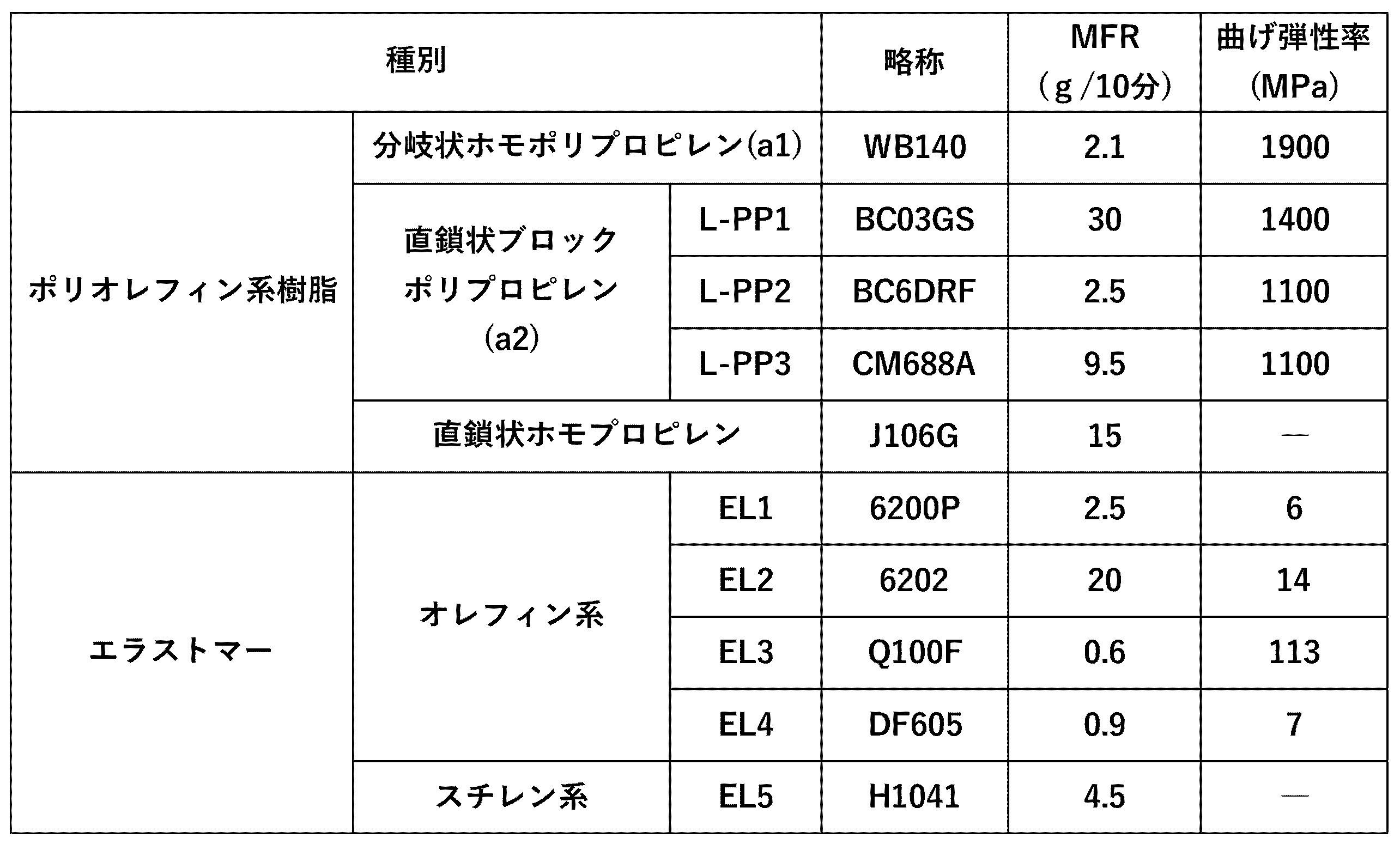
- linear block polypropylene (a2) those shown in L-PP1 to L-PP3 in Table 1 were prepared.
- L-PP1 is a copolymer of propylene and ethylene (propylene-ethylene copolymer) (manufactured by Nippon Polypro Co., Ltd., trade name "Novatec (trademark) PP (model number BC03GS)").
- the propylene-ethylene copolymer of L-PP1 is a Ziegler-catalyzed copolymer (MFR is 30 g/10 min).
- L-PP2 is a polypropylene block copolymer manufactured by Nippon Polypropylene Co., Ltd. under the trade name "Novatec PP (model number BC6DRF)" (MFR is 2.5 g/10 minutes).
- L-PP3 is a propylene block copolymer (manufactured by Sun Allomer Co., Ltd., trade name "Qualia (trademark) (model number CM688A)”) containing an ethylene- ⁇ -olefin copolymer (MFR is 15 g/10 minutes).
- MFR ethylene- ⁇ -olefin copolymer
- the MFR of the propylene block copolymer of L-PP3 is 9.5 g/10 minutes.
- the linear homopolypropylene was prepared under the trade name "Prime Polypro (trademark) (model number J106G)" manufactured by Prime Polymer Co., Ltd. In Table 4, the prepared linear homopolypropylene is abbreviated as J106G.
- olefin elastomers shown in EL1 to EL4 and styrene elastomers shown in EL5 were prepared.
- EL1 is a hydrogenated triblock copolymer consisting of a crystalline olefin polymer block and a conjugated diene compound polymer block.
- EL1 is a hydrogenated block copolymer in which the block portions at both ends are ethylene polymer blocks and the central block portion is a polymer block of a conjugated diene compound (manufactured by JSR Corporation, product name: Dynalon (trademark)).
- 6200P'' (30% by mass of ethylene-derived components in the block copolymer, 70% by mass of 1,3-butadiene-derived components, hydrogenation rate (hydrogenation rate) of 98% or more, melting point 97°C, crystallization A temperature of 64° C.) was prepared.
- EL1 corresponds to the olefin thermoplastic elastomer (B).
- EL2 is a metallocene propylene-ethylene copolymer (manufactured by ExxonMobil, trade name "Vistamax (trademark) 6202, melting point 102°C”).
- EL3 is RPTO (Reactor TPO (Thermoplastic Olefinic Elastomer)) (manufactured by Basell Corporation, trade name “Cataroy (model number Q100F)", melting point 143°C, crystallization temperature 96°C).
- RPTO is a propylene-based random block copolymer that is sequentially polymerized using a Ziegler catalyst.
- EL4 is an ethylene butene block copolymer (manufactured by Mitsui Chemicals, Inc., trade name "Tafmer (trademark) (model number DF605)", melting point 50° C. or lower).
- EL5 is a hydrogenated styrenic thermoplastic elastomer obtained by hydrogenating the double bonds of a block copolymer made of styrene and butadiene (manufactured by Asahi Kasei Corporation, product name: "Tuftec (trademark) (model number H1041)”)
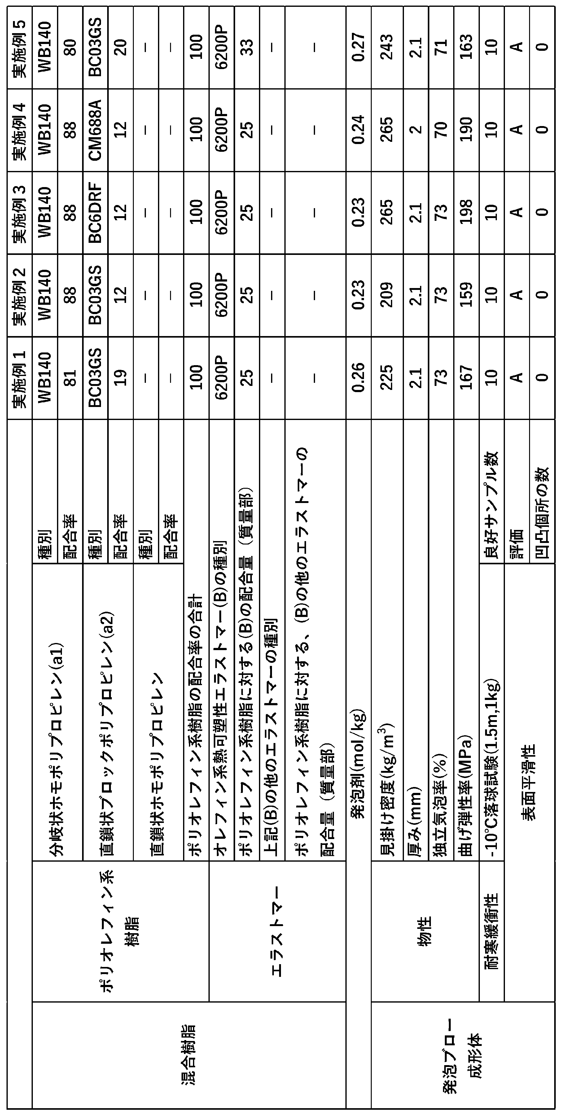
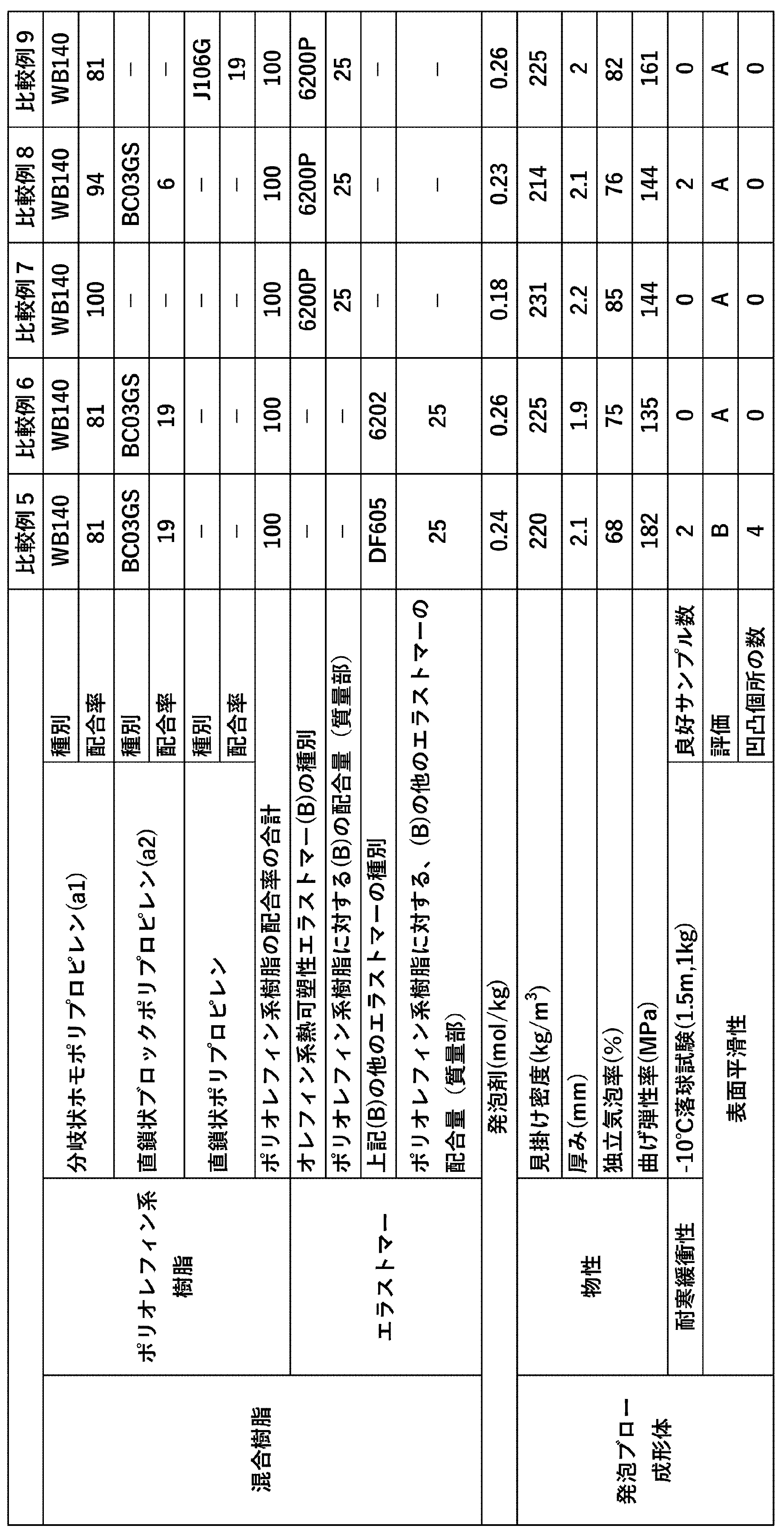
- Examples 1 to 5 Comparative Examples 1 to 9 (Extrusion foaming process) Polyolefin resins and elastomers of the types and amounts (mass%) shown in Table 2 (Examples 1 to 5), Table 3 (Comparative Examples 1 to 4), and Table 4 (Comparative Examples 5 to 9), and additions described below.
- the agent was supplied to an extruder with a diameter of 65 mm, and melted and kneaded in the extruder to obtain a resin melt. Furthermore, carbon dioxide (CO 2 ) was pressurized as a foaming agent into the extruder and kneaded with the resin melt to obtain a foamable resin melt.
- the foamable resin melt was charged into an accumulator connected to an extruder.
- the foamable resin melt was extruded into a normal pressure region through an annular die placed at the tip of an accumulator and foamed, thereby forming a cylindrical foamed parison.
- Pre-blow process A two-part mold was placed directly below the annular die, and a cylindrical foam parison formed in the extrusion foaming process was placed between the molds. Furthermore, after the opening of the foamed parison is closed below the mold using a pinch, pre-blow air is blown into the foamed parison, and the two-part mold is further closed, allowing foaming to occur in the mold. The parison was pinched.
- Blow air is blown from a blow pin into the inside of the foamed parison sandwiched between the molds, and the air is sucked through holes provided in the mold to reduce the pressure in the space between the outer surface of the foamed parison and the inner surface of the mold. This pressed the outer surface of the foamed parison against the inner surface of the mold. The foamed parison was then shaped to correspond to the inner surface of the mold. After shaping and cooling, the mold, which is a mold, was opened, the molded product was taken out, and burrs and pockets were removed. As a result, a foam blow-molded article was obtained.
- the obtained foam blow molded article was formed into a hollow shape, and was formed into a shape corresponding to a duct having a generally rectangular cylindrical cross section and a maximum length of 650 mm and a maximum width of 180 mm.
- the hollow portion of the foam blow-molded product may be particularly referred to as the hollow portion.
- the mixed resin contains 0.9 parts by mass of carbon black and 2 parts by mass of talc as additives for a total of 100 parts by mass of the polyolefin resin (A) and the olefin thermoplastic elastomer (B). They were added as carbon black masterbatch (45% masterbatch (MB)) and talc masterbatch (20% masterbatch (MB)).
- the carbon black masterbatch is manufactured by B&Tech Corporation and has a trade name of "PP Black Master Batch, BT920F-JSJ".
- the talc masterbatch is manufactured by Matsumura Sangyo and has the trade name "High Filler #12" (talc concentration 20% by mass, median diameter 7.5 ⁇ m). Note that talc can function as a bubble regulator.
- the amount of blowing agent injected (mol/kg) is as shown in Table 2, Table 3, and Table 4. Note that the amount of blowing agent injected shown in Tables 2, 3, and 4 is the amount (mol/kg) per 1 kg of the mixed resin of polyolefin resin and elastomer.
- the apparent density, closed cell ratio, and flexural modulus of the foam blow-molded product were measured by the methods described above.
- the thickness of the foam blow-molded article indicates the average thickness of the foam blow-molded article, and is a value measured by the following method. Vertical cross sections with respect to the longitudinal direction of the foam blow-molded article are obtained at five parts in total, including the longitudinal center portion, the vicinity of both longitudinal end portions, and the intermediate portion between the center portion and both end portions. The thickness (wall thickness) of the foam blow-molded product was measured at 6 points equally spaced in the circumferential direction of each vertical cross section, and the maximum and minimum values were excluded from the obtained thickness measurements at 30 points. The arithmetic mean value of was taken as the average thickness of the foam blow-molded product.
- the cold impact resistance of the foam blow-molded product was evaluated by performing a -10°C falling ball test (1.5 m, 1 kg).
- Example 2 For each Example and Comparative Example, 10 samples were prepared as foam blow-molded bodies for conducting a -10°C falling ball test, and each sample was used to evaluate the cold impact resistance of the foam blow-molded bodies. The number of samples with a result of A or B (number of good samples) was counted. The results are shown in Tables 2, 3 and 4.
- the surface smoothness of the foam blow-molded article refers to the smoothness of the inner surface of the hollow portion of the foam blow-molded article.
- the surface smoothness of the foam blow-molded article was measured by cutting out a flat part of the hollow part of the hollow foam blow-molding article and visually observing the inner surface of the foam blow-molded article in the flat part.
- the surface smoothness of the foam blow-molded product was measured according to the following criteria.
- the column for surface smoothness includes the number of recognized unevenness formation locations in addition to the above evaluation results.
- the number of unevenness formation locations was 0 (that is, no unevenness was observed on the inner surface).
- Comparative Examples 1 and 2 the blending ratio of polyolefin resin and elastomer in the mixed resin was changed compared to Example 2, and as shown in Table 3, the impact resistance and surface required for the foam blow-molded product were improved. It was not possible to achieve both smoothness and smoothness.
- Comparative Examples 3 to 6 the type of elastomer was changed compared to Example 1, etc., and as shown in Tables 3 and 4, the impact resistance and surface smoothness required for foam blow-molded products were improved. It was not possible to achieve both.
- Comparative Example 7 and Comparative Example 8 the blending amount of linear block polypropylene (a) was changed compared to Example 1, etc., and as shown in Table 4, the impact resistance required for the foam blow molded product was improved. It was not possible to achieve both surface smoothness and surface smoothness. Furthermore, in Comparative Examples 7 and 8, as shown in Table 4, the values of the flexural modulus were lower than those of Examples 1 to 5, and the rigidity of the foam blow-molded products was insufficient.
- the manufacturing method and examples of the present invention described above are merely examples, and the present invention is not limited thereto.
- various attributes of the branched homopolypropylene (a1) may be combined.
- the branched homopolypropylene (a1) may have a specific melt tension and a specific melting point. The same applies not only to the branched homopolypropylene (a1) but also to the linear block polypropylene (a2), the olefin thermoplastic elastomer (B), and the recovered raw material.
- the combinations listed here are just examples and are not limited thereto.
Landscapes
- Chemical & Material Sciences (AREA)
- Engineering & Computer Science (AREA)
- Manufacturing & Machinery (AREA)
- Mechanical Engineering (AREA)
- Materials Engineering (AREA)
- Health & Medical Sciences (AREA)
- Chemical Kinetics & Catalysis (AREA)
- Medicinal Chemistry (AREA)
- Polymers & Plastics (AREA)
- Organic Chemistry (AREA)
- Manufacture Of Porous Articles, And Recovery And Treatment Of Waste Products (AREA)
- Blow-Moulding Or Thermoforming Of Plastics Or The Like (AREA)
Abstract
Description
前記ポリオレフィン系樹脂(A)が、分岐状ホモポリプロピレン(a1)と直鎖状ブロックポリプロピレン(a2)とからなり、且つ、前記分岐状ホモポリプロピレン(a1)と前記直鎖状ブロックポリプロピレン(a2)との質量比[(a1):(a2)]が、50:50~93:7であり、
前記オレフィン系熱可塑性エラストマー(B)が、結晶性オレフィン重合体ブロックと共役ジエン化合物の重合体ブロックからなるトリブロック共重合体の水素添加物であり、
前記混合樹脂においては、前記ポリオレフィン系樹脂(A)100質量部に対する前記オレフィン系熱可塑性エラストマー(B)の配合量が、20質量部以上40質量部以下である、発泡ブロー成形体の製造方法。
(2)前記オレフィン系熱可塑性エラストマー(B)の融点が80℃以上100℃以下である、
上記(1)に記載の発泡ブロー成形体の製造方法。
(3)前記直鎖状ブロックポリプロピレン(a2)の曲げ弾性率が1000MPa以上1500MPa以下である、
上記(1)又は(2)に記載の発泡ブロー成形体の製造方法。
(4)前記オレフィン系熱可塑性エラストマー(B)のメルトフローレイト(230℃、荷重2.16kg)が1g/10min以上10g/10min以下である、
上記(1)から(3)のいずれかに記載の発泡ブロー成形体の製造方法。
(5)ポリオレフィン系樹脂(A)とオレフィン系熱可塑性エラストマー(B)との混合樹脂の発泡ブロー成形体であって、
前記ポリオレフィン系樹脂(A)が、分岐状ホモポリプロピレン(a1)と直鎖状ブロックポリプロピレン(a2)とからなり、且つ、前記分岐状ホモポリプロピレン(a1)と前記直鎖状ブロックポリプロピレン(a2)との質量比[(a1):(a2)]が、50:50~93:7であり、
前記オレフィン系熱可塑性エラストマー(B)が、結晶性オレフィン重合体ブロックと共役ジエン化合物の重合体ブロックからなるトリブロック共重合体の水素添加物であり、
前記混合樹脂においては、前記ポリオレフィン系樹脂(A)100質量部に対する前記オレフィン系熱可塑性エラストマー(B)の配合量が、20質量部以上40質量部以下である、発泡ブロー成形体。
上記(5)に記載の発泡ブロー成形体。
(7)前記直鎖状ブロックポリプロピレン(a2)の曲げ弾性率が1000MPa以上1500MPa以下である、
上記(5)又は(6)に記載の発泡ブロー成形体。
(8)前記オレフィン系熱可塑性エラストマー(B)のメルトフローレイト(230℃、荷重2.16kg)が1g/10min以上10g/10min以下である、
上記(5)から(7)のいずれか1つに記載の発泡ブロー成形体。
本発明にかかる製造方法は、ブロー成形工程を有する発泡ブロー成形体の製造方法である。本発明にかかる発泡ブロー成形体の製造方法の一実施例について説明を続ける。
(押出発泡工程)
押出機の内部において、混合樹脂及び発泡剤が混練されることにより発泡性樹脂溶融物を得る。得られた発泡性樹脂溶融物は、押出機に繋げられたダイから押し出される。ダイとしては、通常、環状ダイが用いられる。ダイの直下には成形型が配置されており、発泡性樹脂溶融物は、成形型の内部に押し出される。このとき、発泡性樹脂溶融物が発泡することにより発泡パリソンが形成される。なお、成形型は、得ようとする成形体に応じた所望の内部形状を有する。成形型は、通常、分割型の金型となっている。
押出発泡工程直後、発泡パリソンは軟化状態にある。ピンチ装置などを用いて軟化状態の発泡パリソンの下部を閉鎖し、発泡パリソンの内部に気体を吹き込むことで発泡パリソンの内部圧力を高める。このとき発泡パリソンが拡幅する。プリブロー工程の段階で又はプリブロー工程の後に、発泡パリソンが成形型に挟み込まれる。
ブロー成形工程は、発泡パリソンを成形型に挟み込んだ状態で発泡パリソンの内部に気体を吹き込む工程である。このとき発泡パリソンの外表面が成形型の内面に押し付けられ、発泡パリソンが中空状に賦形される。この工程により発泡ブロー成形体が得られる。発泡ブロー成形体としては、例えば中空状の成形体が得られる。なお、発泡ブロー成形体の製造方法においては、アキュームレーターが押出機とダイとの間、またはダイに設けられることが好ましい。
発泡性樹脂溶融物を形成するための混合樹脂は、ポリオレフィン系樹脂(A)とオレフィン系熱可塑性エラストマー(B)との混合樹脂である。
ポリオレフィン系樹脂(A)は、分岐状ホモポリプロピレン(a1)と直鎖状ブロックポリプロピレン(a2)とからなる樹脂組成物である。
分岐状ホモポリプロピレン(a1)は、分子構造中に分岐構造を有するホモポリプロピレンである。分岐構造としては、分子構造中における枝分かれした構造部分、且つ長鎖状構造部分で自由末端を有する構造部分を、例示することができる。なお、分岐構造は高温GPC-MALS測定等を用いて確認することができる。
直鎖状ブロックポリプロピレン(a2)は、直鎖状の分子構造を有するブロックポリプロピレンである。ブロックポリプロピレンとしては、プロピレン重合体の存在下、エチレンと1種類以上のC3~C10-αオレフィン(炭素数が3から10のα-オレフィン)を重合して得た重合混合物が挙げられる。また、直鎖状ブロックポリプロピレン(a2)はJIS K6921-1で規定される耐衝撃性ポリプロピレンポリマーを含み、一般にブロックポリプロピレンとして市販されているものを含む。ただし、ここに示すブロックポリプロピレンの例は一例であり、他の例を排除するものではない。具体的には、ブロックポリプロピレンは、プロピレン・エチレンブロック共重合体を例示することができる。さらに具体的には、プロピレン・エチレンブロック共重合体は、結晶性のプロピレンブロックと、エチレンプロピレンランダムブロックを含有するブロック共重合体が挙げられる。
直鎖状ブロックポリプロピレン(a2)の曲げ弾性率は、1000MPa以上1500MPa以下であることが好ましい。直鎖状ブロックポリプロピレン(a2)の曲げ弾性率が1000MPa以上であることで、発泡ブロー成形体の剛性をより効果的に向上させるとともに、発泡ブロー成形体の緩衝性を向上させることができる。この観点からは、直鎖状ブロックポリプロピレン(a2)の曲げ弾性率が1100MPa以上1400MPa以下であることがより好ましい。直鎖状ブロックポリプロピレン(a2)の曲げ弾性率の数値範囲は、上記に記載した数値範囲の組み合わせに示される上限値とおよび下限値は独立して任意に組み合わせることが可能である。上限値及び下限値を任意に組み合わせることで定められる数値範囲には、上限値、下限値、及び上限値と下限値との間の値が含まれる。直鎖状ホモポリプロピレン(a2)の曲げ弾性率の数値範囲は、例えば、1000MPa、及び1100MPaからなる群のいずれか1つを下限値とし、且つ1500MPa、及び1400MPaからなる群のいずれか1つを上限値とする範囲を挙げることができる。
直鎖状ブロックポリプロピレン(a2)の曲げ弾性率は、JIS K7171:2016に基づき測定することができる。
前記混合樹脂では、分岐状ホモポリプロピレン(a1)と直鎖状ブロックポリプロピレン(a2)の質量比[(a1):(a2)]が、50:50~93:7であることが好ましい。質量比[(a1):(a2)]が上記した数値の範囲にあることで、混合樹脂の発泡性が向上して表面平滑性が向上すると共に発泡ブロー成形体の剛性、耐寒衝撃性を良好とする効果が得られる。なお、この効果をさらに向上させる観点からは、質量比[(a1):(a2)]が70:30~92:8であることが好ましく、さらには80:20~90:10であることが好ましい。質量比[(a1):(a2)]の数値範囲は、上記に記載した数値範囲の組み合わせに示される上限となる比率とおよび下限となる比率は独立して任意に組み合わせることが可能である。上限となる比率及び下限となる比率を任意に組み合わせることで定められる数値範囲には、上限となる比率、下限となる比率、及び上限となる比率と下限となる比率との間の比率が含まれる。ただし、質量比[(a1):(a2)]のそれぞれの数値範囲の組み合わせにおいて分岐状ホモポリプロピレン(a1)の質量比率が最も小さい場合を下限となる比率とし、分岐状ホモポリプロピレン(a1)の質量比率が最も大きい場合を上限となる比率とする。例えば、質量比[(a1):(a2)]の数値範囲が、50:50~93:7である場合には、下限となる比率は、50:50であり、上限となる比率は93:7である。質量比[(a1):(a2)]の数値範囲は、例えば、50:50、70:30、及び80:20からなる群のいずれか1つを下限となる比率とし、且つ93:7、92:8及び90:10からなる群のいずれか1つを上限となる値とする範囲を挙げることができる。
オレフィン系熱可塑性エラストマー(B)は、結晶性オレフィンの重合体ブロックのハードセグメントと共役ジエン化合物の重合体ブロックのソフトセグメントからなるトリブロック共重合体の水素添加物である。トリブロック共重合体は、いわゆるA-B-A型の構造(サンドイッチ型)となるブロック共重合体であることが好適である。このとき、A-B-A型の構造となるブロック共重合体のうち両端のブロック部としてのAは、結晶性オレフィンの重合体ブロックであり、Aで挟まれたブロック部(中央のブロック部)としてのBは、共役ジエン化合物の重合体ブロックであることが好ましい。オレフィン系熱可塑性エラストマー(B)が上記したような構造を有するブロック共重合体の水素添加物であることで、発泡パリ孫の発泡性を阻害せずに発泡ブロー成形体の耐衝撃性を向上させることができる。また、発泡ブロー成形体の表面平滑性が向上するという効果を発揮させることができる。
オレフィン系熱可塑性エラストマー(B)の融点は、80℃以上110℃以下であることが好ましい。オレフィン系熱可塑性エラストマー(B)の融点が上記範囲であれば、発泡性に優れるものとなる。この観点からは、オレフィン系熱可塑性エラストマー(B)の融点が85℃以上105℃以下であることがより好ましく、90℃以上100℃以下であることがさらに好ましい。オレフィン系熱可塑性エラストマー(B)の融点の数値範囲は、上記に記載した数値範囲の組み合わせに示される上限値とおよび下限値は独立して任意に組み合わせることが可能である。上限値及び下限値を任意に組み合わせることで定められる数値範囲には、上限値、下限値、及び上限値と下限値との間の値が含まれる。オレフィン系熱可塑性エラストマー(B)の融点の数値範囲は、例えば、80℃、85℃及び90℃からなる群のいずれか1つを下限値とし、且つ110℃、105℃及び100℃からなる群のいずれか1つを上限値とする範囲を挙げることができる。
オレフィン系熱可塑性エラストマー(B)の融点は、JIS K7121:2012に記載の熱流束示差走査熱量測定に基づき測定された融解ピーク温度として特定することができる。なお、熱流束示差走査熱量測定に用いられる試験片の状態調節としては「(2)一定の熱処理を行なった後、融解温度を測定する場合」を採用し、加熱速度及び冷却速度としては共に10℃/分を採用する。DSC曲線に複数の融解ピークが表れる場合は、最も面積の大きな融解ピークの頂点温度を融点とする。
オレフィン系熱可塑性エラストマー(B)の曲げ弾性率の上限については、50MPaであることが好ましい。オレフィン系熱可塑性エラストマー(B)の曲げ弾性率が50MPa以下であることで、オレフィン系熱可塑性エラストマー(B)はエラストマーとしての物性を効果的に発揮することができる。また、オレフィン系熱可塑性エラストマー(B)の曲げ弾性率の下限については、おおむね1Maであることが好ましい。すなわち、オレフィン系熱可塑性エラストマー(B)の曲げ弾性率が1MPa以上50MPa以下であることが好ましい。オレフィン系熱可塑性エラストマー(B)の曲げ弾性率が上記の数値範囲にあることで、発泡ブロー成形体として耐寒衝撃性をさらに向上させる効果を得ることが容易となる。この効果をより高める観点からは、オレフィン系熱可塑性エラストマー(B)の曲げ弾性率が3MPa以上30MPa以下であることがより好ましく、5MPa以上25MPa以下であることがさらに好ましい。オレフィン系熱可塑性エラストマー(B)の曲げ弾性率の数値範囲は、上記に記載した数値範囲の組み合わせに示される上限値とおよび下限値は独立して任意に組み合わせることが可能である。上限値及び下限値を任意に組み合わせることで定められる数値範囲には、上限値、下限値、及び上限値と下限値との間の値が含まれる。オレフィン系熱可塑性エラストマー(B)の曲げ弾性率の数値範囲は、例えば、1MPa、3MPa及び5MPaからなる群のいずれか1つを下限値とし、且つ50MPa、30MPa及び25MPaからなる群のいずれか1つを上限値とする範囲を挙げることができる。
オレフィン系熱可塑性エラストマー(B)の曲げ弾性率は、JIS K7171:2016に基づき測定することができる。
オレフィン系熱可塑性エラストマー(B)のMFR(230℃、荷重2.16kg)は、1g/10分以上10g/10分以下であることが好ましく、1.5g/10分以上5g/10分以下であることがさらに好ましい。オレフィン系熱可塑性エラストマー(B)のMFRの数値範囲は、上記に記載した数値範囲の組み合わせに示される上限値とおよび下限値は独立して任意に組み合わせることが可能である。上限値及び下限値を任意に組み合わせることで定められる数値範囲には、上限値、下限値、及び上限値と下限値との間の値が含まれる。オレフィン系熱可塑性エラストマー(B)のMFRの数値範囲は、例えば、1g/10分、及び1.5g/10分からなる群のいずれか1つを下限値とし、且つ10g/10分、及び5g/10分からなる群のいずれか1つを上限値とする範囲を挙げることができる。
オレフィン系熱可塑性エラストマー(B)のMFR(g/10min(230℃))は、例えばJIS K7210-1:2014(試験方法A法)に基づき求められる。測定条件としては、230℃、荷重2.16kgの条件が採用されてよい。
前記混合樹脂においては、ポリオレフィン系樹脂(A)100質量部に対するオレフィン系熱可塑性エラストマー(B)の配合量が、20質量部以上40質量部以下である。ポリオレフィン系樹脂(A)100質量部に対するオレフィン系熱可塑性エラストマー(B)の配合量が上記範囲であることで、発泡ブロー成形体に求められる耐衝撃性と表面平滑性の両立を実現させることが容易となる。上記観点から、オレフィン系熱可塑性エラストマー(B)の配合量は、22質量部以上35質量部以下が好ましく、23質量部以上30質量部以下がより好ましい。
発泡ブロー成形体を製造する際、上記したように混合樹脂と発泡剤が混錬される。物理発泡剤としては、次に示すようなものを挙げることができる。
発泡剤としては、例えば、プロパン、ノルマルブタン、イソブタン、ノルマルペンタン、イソペンタン、ノルマルヘキサン、イソヘキサン、シクロヘキサン等の脂肪族炭化水素、塩化メチル、塩化エチル等の塩化炭化水素、1,1,1,2-テトラフロロエタン、1,1-ジフロロエタン等のフッ化炭化水素、ジメチルエーテル、ジエチルエーテル、メチルエチルエーテル等の脂肪族エーテル、メチルアルコール、エチルアルコール等の脂肪族アルコール、ジメチルカーボネート、ジエチルカーボネート等のジアルキルカーボネートなどの有機系物理発泡剤、二酸化炭素、窒素、空気、水等の無機系物理発泡剤、炭酸水素ナトリウム、クエン酸ナトリウム、アゾジカルボンアミド等の化学発泡剤が挙げられる。これらの発泡剤は、単独で又は混合して用いられる。
混合樹脂には、ポリオレフィン系樹脂(A)及びオレフィン系熱可塑性エラストマー(B)とは異なるその他の樹脂を、本発明の目的効果を阻害しない範囲で、配合することができる。その他の樹脂としては、ポリスチレン系樹脂、ポリオレフィン系樹脂(A)以外のポリオレフィン系樹脂等の熱可塑性樹脂や、オレフィン系熱可塑性エラストマー(B)以外の熱可塑性エラストマー(TPE)を配合することができる。また、ポリオレフィン系樹脂(A)以外のポリオレフィン系樹脂として、バイオマスポリオレフィン系樹脂、ASR由来のポリオレフィン系樹脂、マスバランスポリオレフィン系樹脂を用いることもできる。その他の樹脂の配合量は、ポリオレフィン系樹脂(A)とオレフィン系熱可塑性エラストマー(B)の合計100質量部に対して好ましくは30質量部以下であり、より好ましくは20質量部以下であり、更に好ましくは10質量部以下であり、特に好ましくは5質量部以下である。
発泡ブロー成形体を製造する際、混合樹脂には、上記した発泡剤の他に各種の添加剤が添加されてよい。添加剤としては、難燃剤、流動調整剤、紫外線吸収剤、導電性付与剤、帯電防止剤、着色剤、熱安定剤、酸化防止剤、無機充填剤、顔料などを例示することができる。上記添加剤の配合量は、ポリオレフィン系樹脂(A)とオレフィン系熱可塑性エラストマー(B)の合計100質量部に対して好ましくは10質量部以下であり、より好ましくは5質量部以下であり、更に好ましくは3質量部以下である。また、上記の添加剤は、ポリオレフィン系樹脂(A)、オレフィン系熱可塑性エラストマー(B)、分岐状ホモポリプロピレン(a1)、及び直鎖状ブロックポリプロピレン(a2)に、本発明の作用効果を阻害しない範囲で添加させることができる。その添加量は、好ましくは、前記ポリオレフィン系樹脂(A)、オレフィン系熱可塑性エラストマー(B)、分岐状ホモポリプロピレン(a1)、及び直鎖状ブロックポリプロピレン(a2)のそれぞれ100質量部に対して、好ましくは10質量部以下であり、より好ましくは5質量部以下であり、更に好ましくは3質量部以下である。
本発明の発泡ブロー成形体を製造する際には、バリや寸法ズレなどが生じた不良成形品などが発生することが起こりうる。これらのバリや不良成形品は、回収原料として用いることができる。回収原料は、ポリオレフィン系樹脂(A)とオレフィン系熱可塑性エラストマー(B)を含むものであることが好ましい。そして、本発明にかかる発泡ブロー成形体の製造方法では、回収原料を含む発泡性樹脂溶融物が形成され、その発泡性樹脂溶融物を発泡させた発泡パリソンにより発泡ブロー成形体が形成されてよい。なお、ポリオレフィン系樹脂(A)とオレフィン系熱可塑性エラストマー(B)を含む回収原料が発泡性樹脂溶融物を形成する際の原料の一部として用いられる場合、発泡ブロー成形体を構成する混合樹脂中のポリオレフィン系樹脂(A)とオレフィン系熱可塑性エラストマー(B)の配合量とは、前記回収原料に含まれるポリオレフィン系樹脂(A)とオレフィン系熱可塑性エラストマー(B)を含む値として定められる。回収原料に含まれるポリオレフィン系樹脂(A)とオレフィン系熱可塑性エラストマー(B)の物性等の属性に関する数値範囲、及び、ポリオレフィン系樹脂(A)とオレフィン系熱可塑性エラストマー(B)の配合量の数値範囲は、発泡ブロー成形体を構成する混合樹脂を構成するポリオレフィン系樹脂(A)とオレフィン系熱可塑性エラストマー(B)について上述したことと同様である。
発泡ブロー成形体においてポリプロピレン系樹脂を用いたものは、耐熱性と軽量性の観点で特に優れるものとなり、例えば自動車等の車両に搭載されるダクトの用途で好適に採用することができる。このような用途で好適に用いられる発泡ブロー成形体については、近年、耐寒衝撃性を向上させたものがさらに要請されている。
[2-1 発泡ブロー成形体の構成]
本発明にかかる発泡ブロー成形体は、ポリオレフィン系樹脂(A)とオレフィン系熱可塑性エラストマー(B)との混合樹脂の発泡成形体である。
発泡ブロー成形体の形状は、特に限定されないが、中空状の成形体であると、例えば車両等に設けられる空調用のダクトとして発泡ブロー成形体を利用することが容易となる。
発泡ブロー成形体の独立気泡率は、外観性を向上させる観点からは、65%以上であることが好ましく、70%以上であることがより好ましい。
発泡ブロー成形体のおおむね平坦部から25mm×25mm×平坦部の肉厚みに切断した試験片を作製する。厚みの総和が20mmに最も近づくように試験片を複数枚重ねて測定用試験片とする。次に、ASTM-D2856-70の手順Cに従って、東芝ベックマン株式会社の空気比較式比重計930型等を使用して測定用試験片の真の体積Vxを測定し、下記数式(式(1))により独立気泡率S(%)を計算する。上記測定を、5個の測定用試験片を用いて行い、その算術平均値を発泡ブロー成形体の独立気泡率とする。

Vx:上記方法で測定された試験片の真の体積(cm3)であり、発泡ブロー成形体を構成する樹脂の体積と、試験片内の独立気泡部分の気泡全体積との和に相当する、
Va:測定に使用された試験片の外寸から計算された試験片の見掛け体積(cm3)、
W:測定に使用された試験片の全質量(g)、そして
ρ:発泡ブロー成形体を構成する樹脂の密度(g/cm3)、
である。
発泡ブロー成形体の見掛け密度が100kg/m3以上450kg/m3以下であることが好ましい。上記見掛け密度を有することで、軽量であるとともに、適度な剛性を有する成形体を安定して得ることができる。軽量性と剛性、更には緩衝性とのバランスの観点からは、発泡ブロー成形体の見掛け密度は、120kg/m3以上400kg/m3以下であることが好ましく、130kg/m3以上350kg/m3以下であることがより好ましく、150kg/m3以上250kg/m3以下であることがさらに好ましい。発泡ブロー成形体の見掛け密度の数値範囲は、上記に記載した数値範囲の組み合わせに示される上限値とおよび下限値は独立して任意に組み合わせることが可能である。上限値及び下限値を任意に組み合わせることで定められる数値範囲には、上限値、下限値、及び上限値と下限値との間の値が含まれる。発泡ブロー成形体の見掛け密度の数値範囲は、例えば、100kg/m3、120kg/m3、130kg/m3及び150kg/m3からなる群のいずれか1つを下限値とし、且つ450kg/m3、400kg/m3、350kg/m3及び250kg/m3からなる群のいずれか1つを上限値とする範囲を挙げることができる。
発泡ブロー成形体の長手方向中央部および長手方向両端部付近の計3箇所の長手方向に対する垂直断面に対して、各垂直断面の周方向の平坦部分において等間隔な4箇所を選択し、平面視での面積約10cm2の試験片を切り出し、そして、各試験片について、その質量Wi[g]を体積Vi[cm3]で除し、単位換算することにより各試験片の見掛け密度(Wi/Vi)を求め、それらの値の算術平均値を見掛け密度(D)とした。
発泡ブロー成形体の曲げ弾性率(MPa)は、140MPa以上250MPa以下であることが好ましい。発泡ブロー成形体の曲げ弾性率が上記の数値範囲にあることで、十分な剛性を確保することが容易となる。この効果をより高める観点からは、発泡ブロー成形体の曲げ弾性率は、150MPa以上200MPa以下であることがより好ましい。発泡ブロー成形体の曲げ弾性率の数値範囲は、上記に記載した数値範囲の組み合わせに示される上限値とおよび下限値は独立して任意に組み合わせることが可能である。上限値及び下限値を任意に組み合わせることで定められる数値範囲には、上限値、下限値、及び上限値と下限値との間の値が含まれる。発泡ブロー成形体の曲げ弾性率の数値範囲は、例えば、140MPa、及び150MPaからなる群のいずれか1つを下限値とし、且つ250MPa、及び200MPaからなる群のいずれか1つを上限値とする範囲を挙げることができる。
発泡ブロー成形体の曲げ弾性率については、発泡ブロー成形体の平坦部分からサンプルを切り出し、そのサンプル片の曲げ弾性率を、JIS K7171:2016に基づいて測定することで、特定することができる。
本発明にかかる発泡ブロー成形体は、上記の[1.発泡ブロー成形体の製造方法]で説明したことと同様に、特定のポリプロピレン系樹脂(ポリオレフィン系樹脂(A))と特定のエラストマー(オレフィン系熱可塑性エラストマー(B))とが特定の範囲で配合された混合樹脂の発泡成形体であることで、耐寒衝撃性と剛性の両方に優れる。また、発泡ブロー成形体は、特定のエラストマーにより構成されていることで、表面平滑性に優れたものとなる。
発泡ブロー成形体を-10℃の雰囲気下で24時間載置することで発泡ブロー成形体の状態調節が行われ、状態調節を行った発泡ブロー成形体のうち平坦部分を上に向けて試験台に載置し、1.5m上方から、1kgの鉄球を平らな部分に向けて落下させる。このとき、発泡ブロー成形体の損傷状態を観察する。発泡ブロー成形体の損傷の程度が少ない(損傷がない場合を含む)ほど、発泡ブロー成形体の耐寒衝撃性に優れる、と評価することができる。
表1に示すポリオレフィン系樹脂、及びエラストマーを準備した。ただし、ポリオレフィン系樹脂については、分岐状ホモポリプロピレン(a1)と直鎖状ブロックポリプロピレン(a2)と直鎖状ホモポリプロピレンが準備された。表1には、準備されたポリオレフィン系樹脂、及びエラストマーの物性(MFR(g/10分(230℃、荷重2.16kg))及び曲げ弾性率(MPa))を合わせて示す。
(押出発泡工程)
表2(実施例1から5)、表3(比較例1から4)、表4(比較例5から9)に示す種類及び配合量(質量%)のポリオレフィン系樹脂、エラストマー、及び後述する添加剤を口径65mmの押出機に供給し、押出機内にて溶融混練して樹脂溶融物とした。さらに、押出機に発泡剤として二酸化炭素(CO2)を圧入し、樹脂溶融物と混練して発泡性樹脂溶融物とした。発泡性樹脂溶融物は、押出機に連結したアキュームレーターに充填された。そして発泡温度170℃にて、アキュームレーターの先端に配置した環状ダイより発泡性樹脂溶融物を常圧域に押出し且つ発泡させることで、円筒状の発泡パリソンを形成した。
環状ダイの直下には成形型として2分割式の金型が配置されており、押出発泡工程で形成された円筒状の発泡パリソンが、金型の間に配置された。さらに、ピンチを用いて金型よりも下方側で発泡パリソンの開口部が閉じられた後、発泡パリソン内にプリブローエアが吹き込まれ、さらに2分割式の金型が閉じられることにより、成形型で発泡パリソンが挟み込まれた。
成形型で挟み込まれた発泡パリソンの内部にブローピンからブローエアが吹き込まれること、及び、金型に設けた孔より吸引することで発泡パリソンの外側面と金型の内面との間の空間を減圧することにより、発泡パリソンの外面を成形型の内面に押し付けた。そして、発泡パリソンに金型内面に対応した形状が賦形された。賦形及び冷却後、成形型である金型を開いて成形体を取り出し、バリ及びポケット部を取り除いた。これにより発泡ブロー成形体が得られた。得られた発泡ブロー成形体は、中空状に形成されており、断面がおおむね矩形の筒状で最大長さ650mm且つ最大幅180mmのダクトに対応する形状に形成された。なお、発泡ブロー成形体の中空状に形成されている部分を特に中空部を称呼する場合がある。
実施例1から5、比較例1から9において得られたそれぞれの発泡ブロー成形体の物性として、見掛け密度(kg/m3)、厚み(mm)、独立気泡率(%)、及び曲げ弾性率(MPa)を測定した。結果を表2、表3及び表4に示す。
発泡ブロー成形体の厚みは、発泡ブロー成形体の平均厚みを示しており、以下の方法により測定される値である。発泡ブロー成形体の長手方向中央部および長手方向両端部付近、さらに中央部と両端部との中間部の計5部位の長手方向に対する垂直断面を得る。各垂直断面の周方向に等間隔に6箇所の発泡ブロー成形体の厚み(肉厚)の測定を行い、得られた30箇所の厚みの測定値から最大値と最小値を除く28箇所の厚みの算術平均値を発泡ブロー成形体の平均厚みとした。
実施例1から5、比較例1から9において得られたそれぞれの発泡ブロー成形体について、耐寒衝撃性及び表面平滑性について評価した。結果を表2、表3及び表4に示す。
発泡ブロー成形体の耐寒衝撃性は、-10℃落球試験(1.5m、1kg)を実施することで評価された。
発泡ブロー成形体を-10℃の雰囲気下、24時間載置して状態調節を行った。状態調節を行った発泡ブロー成形体を、平坦部分を上に向けて試験台に載置し、1.5m上方から、1kgの鉄球を平らな部分に向けて落下させ、発泡ブロー成形体の損傷を観察した。落球試験は、5回実施された。なお、発泡ブロー成形体のうち落球が衝突した平らな部分(平坦部分)が撓み、平らな部分以外(平坦部分から外れた場所)に力がかかって発泡ブロー成形体が損傷した場合には、落球試験の回数に計上せずに、落球試験を再度行った。落球試験の結果に基づき、次の基準で発泡ブロー成形体の耐寒衝撃性を評価した。
B(良好):発泡ブロー成形体に割れが認められるが破片の飛び散りが認められない。
C(不良):発泡ブロー成形体が割れ、且つ、発泡ブロー成形体の割れた破片の飛び散りが認められる。
発泡ブロー成形体の表面平滑性とは、発泡ブロー成形体の中空部の内面側表面の平滑性を示す。発泡ブロー成形体の表面平滑性は、中空状の発泡ブロー成形体における中空部の平坦部分を切り出して、その平坦部分における発泡ブロー成形体の内側表面を目視により観察することで、実施された。発泡ブロー成形体の表面平滑性は、次に示す基準で実施された。
B(不良):発泡ブロー成形体の中空部の内側表面を目視した場合に、隣接する凹凸の高低差(凹部の底位置と凸部の先端位置の差)が1mm以上となるような凹凸の形成箇所が、中空部の内側表面の100cm2の領域当たり2か所以上である。

Claims (5)
- ポリオレフィン系樹脂(A)とオレフィン系熱可塑性エラストマー(B)との混合樹脂を発泡させた発泡パリソンをブロー成形する工程を含む発泡ブロー成形体の製造方法であって、
前記ポリオレフィン系樹脂(A)が、分岐状ホモポリプロピレン(a1)と直鎖状ブロックポリプロピレン(a2)とからなり、且つ、前記分岐状ホモポリプロピレン(a1)と前記直鎖状ブロックポリプロピレン(a2)との質量比[(a1):(a2)]が、50:50~93:7であり、
前記オレフィン系熱可塑性エラストマー(B)が、結晶性オレフィン重合体ブロックと共役ジエン化合物の重合体ブロックからなるトリブロック共重合体の水素添加物であり、
前記混合樹脂においては、前記ポリオレフィン系樹脂(A)100質量部に対する前記オレフィン系熱可塑性エラストマー(B)の配合量が、20質量部以上40質量部以下である、発泡ブロー成形体の製造方法。 - 前記オレフィン系熱可塑性エラストマー(B)の融点が80℃以上100℃以下である、
請求項1に記載の発泡ブロー成形体の製造方法。 - 前記直鎖状ブロックポリプロピレン(a2)の曲げ弾性率が1000MPa以上1500MPa以下である、
請求項1又は2に記載の発泡ブロー成形体の製造方法。 - 前記オレフィン系熱可塑性エラストマー(B)のメルトフローレイト(230℃、荷重2.16kg)が1g/10min以上10g/10min以下である、
請求項1から3のいずれか1項に記載の発泡ブロー成形体の製造方法。 - ポリオレフィン系樹脂(A)とオレフィン系熱可塑性エラストマー(B)との混合樹脂の発泡ブロー成形体であって、
前記ポリオレフィン系樹脂(A)が、分岐状ホモポリプロピレン(a1)と直鎖状ブロックポリプロピレン(a2)とからなり、且つ、前記分岐状ホモポリプロピレン(a1)と前記直鎖状ブロックポリプロピレン(a2)との質量比[(a1):(a2)]が、50:50~93:7であり、
前記オレフィン系熱可塑性エラストマー(B)が、結晶性オレフィン重合体ブロックと
共役ジエン化合物の重合体ブロックからなるトリブロック共重合体の水素添加物であり、
前記混合樹脂においては、前記ポリオレフィン系樹脂(A)100質量部に対する前記オレフィン系熱可塑性エラストマー(B)の配合量が、20質量部以上40質量部以下である、発泡ブロー成形体。
Priority Applications (1)
| Application Number | Priority Date | Filing Date | Title |
|---|---|---|---|
| CN202380054627.2A CN119585347A (zh) | 2022-07-19 | 2023-07-18 | 发泡吹塑成型体的制造方法和发泡吹塑成型体 |
Applications Claiming Priority (2)
| Application Number | Priority Date | Filing Date | Title |
|---|---|---|---|
| JP2022-115020 | 2022-07-19 | ||
| JP2022115020A JP7822885B2 (ja) | 2022-07-19 | 2022-07-19 | 発泡ブロー成形体の製造方法、及び発泡ブロー成形体 |
Publications (1)
| Publication Number | Publication Date |
|---|---|
| WO2024019042A1 true WO2024019042A1 (ja) | 2024-01-25 |
Family
ID=89617725
Family Applications (1)
| Application Number | Title | Priority Date | Filing Date |
|---|---|---|---|
| PCT/JP2023/026245 Ceased WO2024019042A1 (ja) | 2022-07-19 | 2023-07-18 | 発泡ブロー成形体の製造方法、及び発泡ブロー成形体 |
Country Status (3)
| Country | Link |
|---|---|
| JP (1) | JP7822885B2 (ja) |
| CN (1) | CN119585347A (ja) |
| WO (1) | WO2024019042A1 (ja) |
Citations (6)
| Publication number | Priority date | Publication date | Assignee | Title |
|---|---|---|---|---|
| JP2009243860A (ja) * | 2008-03-31 | 2009-10-22 | Kyoraku Co Ltd | 軽量空調ダクト |
| JP2018141031A (ja) * | 2017-02-27 | 2018-09-13 | キョーラク株式会社 | 発泡成形用樹脂、発泡成形体及びその製造方法 |
| WO2020059112A1 (ja) * | 2018-09-21 | 2020-03-26 | 株式会社ジェイエスピー | ポリプロピレン系樹脂発泡成形体の製造方法 |
| JP2020132856A (ja) * | 2019-02-15 | 2020-08-31 | 日本ポリプロ株式会社 | ポリプロピレン系樹脂組成物および発泡シート |
| JP2022115508A (ja) * | 2021-01-28 | 2022-08-09 | 株式会社ジェイエスピー | 発泡ブロー成形体 |
| CN115232396A (zh) * | 2022-07-12 | 2022-10-25 | 广州汽车集团股份有限公司 | 一种聚丙烯复合材料、汽车风管及其制备方法 |
-
2022
- 2022-07-19 JP JP2022115020A patent/JP7822885B2/ja active Active
-
2023
- 2023-07-18 CN CN202380054627.2A patent/CN119585347A/zh active Pending
- 2023-07-18 WO PCT/JP2023/026245 patent/WO2024019042A1/ja not_active Ceased
Patent Citations (6)
| Publication number | Priority date | Publication date | Assignee | Title |
|---|---|---|---|---|
| JP2009243860A (ja) * | 2008-03-31 | 2009-10-22 | Kyoraku Co Ltd | 軽量空調ダクト |
| JP2018141031A (ja) * | 2017-02-27 | 2018-09-13 | キョーラク株式会社 | 発泡成形用樹脂、発泡成形体及びその製造方法 |
| WO2020059112A1 (ja) * | 2018-09-21 | 2020-03-26 | 株式会社ジェイエスピー | ポリプロピレン系樹脂発泡成形体の製造方法 |
| JP2020132856A (ja) * | 2019-02-15 | 2020-08-31 | 日本ポリプロ株式会社 | ポリプロピレン系樹脂組成物および発泡シート |
| JP2022115508A (ja) * | 2021-01-28 | 2022-08-09 | 株式会社ジェイエスピー | 発泡ブロー成形体 |
| CN115232396A (zh) * | 2022-07-12 | 2022-10-25 | 广州汽车集团股份有限公司 | 一种聚丙烯复合材料、汽车风管及其制备方法 |
Also Published As
| Publication number | Publication date |
|---|---|
| CN119585347A (zh) | 2025-03-07 |
| JP2024013089A (ja) | 2024-01-31 |
| JP7822885B2 (ja) | 2026-03-03 |
Similar Documents
| Publication | Publication Date | Title |
|---|---|---|
| KR100978771B1 (ko) | 폴리프로필렌계 수지 중공형상 발포 성형체 및 이의제조방법 | |
| US10487188B2 (en) | Propylene resin foamed particle and foamed particle molded body | |
| KR101639466B1 (ko) | 폴리프로필렌계 수지 발포 블로우 성형체의 제조 방법 | |
| US8448671B2 (en) | Light-weight air conditioning duct for vehicle | |
| JP5360975B2 (ja) | ポリエチレン系樹脂発泡ブロー成形体の製造方法およびポリエチレン系樹脂発泡ブロー成形体 | |
| US20060194892A1 (en) | Blended foam having improved flexibility at sub-freezing temperatures | |
| WO2020059112A1 (ja) | ポリプロピレン系樹脂発泡成形体の製造方法 | |
| JP7576987B2 (ja) | 発泡ブロー成形体 | |
| JP7433116B2 (ja) | 射出発泡成形用ポリプロピレン樹脂組成物及びそれを用いた射出発泡ポリプロピレン樹脂組成物成形体 | |
| JP2011052038A (ja) | 発泡中空成形用ポリエチレン | |
| JP5428061B2 (ja) | 発泡ブロー成形品 | |
| JP7822885B2 (ja) | 発泡ブロー成形体の製造方法、及び発泡ブロー成形体 | |
| JP7191495B2 (ja) | 発泡性ポリオレフィン組成物およびその方法 | |
| JP4963266B2 (ja) | ポリプロピレン系樹脂射出発泡成形体 | |
| JP2020093562A (ja) | 車両用空調ダクト | |
| JP7519233B2 (ja) | ポリオレフィン系樹脂発泡ブロー成形体の製造方法 | |
| JP2004307665A (ja) | ポリプロピレン樹脂組成物及びその発泡成形体 | |
| JP2018141031A (ja) | 発泡成形用樹脂、発泡成形体及びその製造方法 | |
| JP2014058624A (ja) | ポリエチレン系発泡中空成形体 | |
| US20220010084A1 (en) | Foam Composition for Vehicle Seat Cushion, Foam for Vehicle Seat Cushion, and Manufacturing Method Therefor | |
| JP2011037922A (ja) | 熱可塑性エラストマー用溶融張力向上剤及びそれを含んでなる熱可塑性エラストマー組成物 | |
| JP2011057826A (ja) | 押出発泡ボード | |
| JP2024116465A (ja) | 発泡ブロー成形体の製造方法 | |
| JP5464888B2 (ja) | 車両用軽量空調ダクト | |
| JP2005153468A (ja) | プロピレン系樹脂発泡シートおよび容器 |
Legal Events
| Date | Code | Title | Description |
|---|---|---|---|
| 121 | Ep: the epo has been informed by wipo that ep was designated in this application |
Ref document number: 23842965 Country of ref document: EP Kind code of ref document: A1 |
|
| WWE | Wipo information: entry into national phase |
Ref document number: 202517004037 Country of ref document: IN Ref document number: 2501000353 Country of ref document: TH Ref document number: 202380054627.2 Country of ref document: CN |
|
| NENP | Non-entry into the national phase |
Ref country code: DE |
|
| WWP | Wipo information: published in national office |
Ref document number: 202380054627.2 Country of ref document: CN |
|
| 122 | Ep: pct application non-entry in european phase |
Ref document number: 23842965 Country of ref document: EP Kind code of ref document: A1 |