WO2024004512A1 - 光ファイバ母材の製造方法 - Google Patents
光ファイバ母材の製造方法 Download PDFInfo
- Publication number
- WO2024004512A1 WO2024004512A1 PCT/JP2023/020492 JP2023020492W WO2024004512A1 WO 2024004512 A1 WO2024004512 A1 WO 2024004512A1 JP 2023020492 W JP2023020492 W JP 2023020492W WO 2024004512 A1 WO2024004512 A1 WO 2024004512A1
- Authority
- WO
- WIPO (PCT)
- Prior art keywords
- heating
- optical fiber
- glass
- fiber preform
- pipe
- Prior art date
- Legal status (The legal status is an assumption and is not a legal conclusion. Google has not performed a legal analysis and makes no representation as to the accuracy of the status listed.)
- Ceased
Links
Images

Classifications
-
- C—CHEMISTRY; METALLURGY
- C03—GLASS; MINERAL OR SLAG WOOL
- C03B—MANUFACTURE, SHAPING, OR SUPPLEMENTARY PROCESSES
- C03B37/00—Manufacture or treatment of flakes, fibres, or filaments from softened glass, minerals, or slags
- C03B37/01—Manufacture of glass fibres or filaments
- C03B37/012—Manufacture of preforms for drawing fibres or filaments
- C03B37/01205—Manufacture of preforms for drawing fibres or filaments starting from tubes, rods, fibres or filaments
- C03B37/01211—Manufacture of preforms for drawing fibres or filaments starting from tubes, rods, fibres or filaments by inserting one or more rods or tubes into a tube
- C03B37/01222—Manufacture of preforms for drawing fibres or filaments starting from tubes, rods, fibres or filaments by inserting one or more rods or tubes into a tube for making preforms of multiple core optical fibres
-
- C—CHEMISTRY; METALLURGY
- C03—GLASS; MINERAL OR SLAG WOOL
- C03B—MANUFACTURE, SHAPING, OR SUPPLEMENTARY PROCESSES
- C03B23/00—Re-forming shaped glass
- C03B23/20—Uniting glass pieces by fusing without substantial reshaping
- C03B23/207—Uniting glass rods, glass tubes, or hollow glassware
-
- C—CHEMISTRY; METALLURGY
- C03—GLASS; MINERAL OR SLAG WOOL
- C03B—MANUFACTURE, SHAPING, OR SUPPLEMENTARY PROCESSES
- C03B37/00—Manufacture or treatment of flakes, fibres, or filaments from softened glass, minerals, or slags
- C03B37/01—Manufacture of glass fibres or filaments
- C03B37/012—Manufacture of preforms for drawing fibres or filaments
- C03B37/01205—Manufacture of preforms for drawing fibres or filaments starting from tubes, rods, fibres or filaments
- C03B37/01225—Means for changing or stabilising the shape, e.g. diameter, of tubes or rods in general, e.g. collapsing
- C03B37/01248—Means for changing or stabilising the shape, e.g. diameter, of tubes or rods in general, e.g. collapsing by collapsing without drawing
-
- C—CHEMISTRY; METALLURGY
- C03—GLASS; MINERAL OR SLAG WOOL
- C03B—MANUFACTURE, SHAPING, OR SUPPLEMENTARY PROCESSES
- C03B37/00—Manufacture or treatment of flakes, fibres, or filaments from softened glass, minerals, or slags
- C03B37/01—Manufacture of glass fibres or filaments
- C03B37/012—Manufacture of preforms for drawing fibres or filaments
- C03B37/01205—Manufacture of preforms for drawing fibres or filaments starting from tubes, rods, fibres or filaments
- C03B37/01225—Means for changing or stabilising the shape, e.g. diameter, of tubes or rods in general, e.g. collapsing
- C03B37/01228—Removal of preform material
Definitions
- the present disclosure relates to a method for manufacturing an optical fiber preform.
- This application claims priority based on Japanese Application No. 2022-102859 filed on June 27, 2022, and incorporates all the contents described in the said Japanese application.
- a rod-in collapse method is known as a method for manufacturing an optical fiber preform (for example, Patent Document 1 and Patent Document 2).
- a core rod is inserted into a clad pipe provided with a hole, and the clad pipe and core rod are integrated by heating.
- a method for manufacturing an optical fiber preform according to one aspect of the present disclosure includes melting and connecting glass pipes to both ends of a clad pipe provided with a hole so as to surround the hole, and connecting the clad pipe and the glass pipe.
- the method includes heating the connection part at a heating temperature below the melting temperature of the connection part, and slowly cooling the connection part from the heating temperature after heating.
- FIG. 1 is a cross-sectional view of an optical fiber preform manufactured in an embodiment.
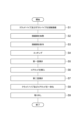
- FIG. 2 is a flowchart showing a method for manufacturing an optical fiber preform according to the embodiment.
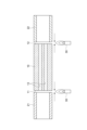
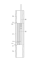
- FIG. 3 is a cross-sectional view for explaining the connection process.
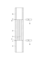
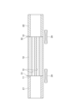
- FIG. 4 is a cross-sectional view for explaining the heating step and slow cooling step.
- FIG. 5 is a cross-sectional view for explaining the etching process.
- FIG. 6 is a cross-sectional view for explaining the insertion process.
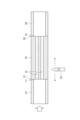
- FIG. 7 is a cross-sectional view for explaining a heating step and a slow cooling step according to a modification.
- An object of the present disclosure is to provide a method for manufacturing an optical fiber preform that can suppress disconnection and cracking of the connection between a clad pipe and a glass pipe.
- a method for manufacturing an optical fiber preform according to one aspect of the present disclosure includes melting and connecting glass pipes to both ends of a clad pipe provided with a hole so as to surround the hole, and connecting the clad pipe and the glass pipe.
- the method includes heating the connection part with the pipe at a heating temperature lower than the melting temperature of the connection part, and gradually cooling the connection part from the heating temperature after heating.
- the glass strain introduced into the joint by the fusion connection of the clad pipe and the glass pipe is released by heating, and the microcracks remaining in the joint are repaired by heating.
- the connecting portion can be cooled to room temperature while suppressing the occurrence of new glass distortion. Therefore, disconnection and cracking of the connection portion can be suppressed.
- the heating time may be 5 minutes or more. In this case, it is easy to release glass distortion and repair microcracks.
- the heating temperature may be 900°C or higher. In this case, it is easy to release glass distortion and repair microcracks.
- the maximum cooling rate until the temperature of the connection part reaches 400°C may be 100°C/min or less. In this case, it is easy to release glass distortion and repair microcracks.
- the surface temperature of the clad pipe at a position 10 mm away from the connection part in the axial direction and the temperature at a position 10 mm away from the connection part in the axial direction may be 0°C or more and 200°C or less. In this case, the occurrence of glass distortion at the connection portion is suppressed.
- heating and slow cooling may be performed using a heating furnace.
- the connection portion since it is easier to heat a wider range than with flame, the connection portion can be heated uniformly. Therefore, glass distortion at the connection portion is easily released.
- heating and slow cooling may be performed using a flame. In this case, it is easier to visually check the connections than in a heating furnace.
- the method for manufacturing the optical fiber preform includes, after slow cooling, flowing gas into the hole to subject the inner surface of the hole to a vapor phase treatment; Alternatively, the method may further include inserting a core rod into the hole, and heating and slow cooling may be performed again after the gas phase treatment or insertion. In this case, glass distortion caused by rapid cooling during the vapor phase treatment process can be released.
- the optical fiber preform may be a multi-core optical fiber preform.
- the diameter of the glass pipe tends to be larger than that of a single-core optical fiber preform.
- Large-diameter glass pipes have larger changes in heat capacity and coefficient of thermal expansion depending on their shape than small-diameter glass pipes. Therefore, glass distortion is likely to be introduced into the connection portion, and microcracks are also likely to remain. Therefore, the effect of heating and slow cooling is large.
- FIG. 1 is a cross-sectional view of the optical fiber preform manufactured in the embodiment. In this figure, a cross section perpendicular to the central axis of the optical fiber preform 1 is shown.
- the optical fiber preform 1 is a multi-core optical fiber preform including a plurality of core parts 2 and a common clad part 3. In this embodiment, the number of core parts 2 is four.
- the plurality of core parts 2 extend along the central axis of the optical fiber preform 1.
- the plurality of core parts 2 are arranged at positions that are rotationally symmetrical with respect to the central axis in a cross section perpendicular to the central axis.
- the cross-sectional shapes of the plurality of core parts 2 are the same circular shape.
- the diameter of the core portion 2 may be, for example, 4 mm or more and 50 mm or less, 5 mm or more and 30 mm or less, or 6 mm or more and 12 mm or less. When made into an optical fiber, the core diameter will be 6 ⁇ m or more and 15 ⁇ m or less.
- the cladding part 3 surrounds the plurality of core parts 2.
- the diameter of the cladding portion 3 may be, for example, 40 mm or more and 180 mm or less, or 40 mm or more and 120 mm or less.
- the diameter of the cladding is 124 ⁇ m or more and 126 ⁇ m or less.
- the refractive index of the core portion 2 is higher than the refractive index of the cladding portion 3.
- the core portion 2 and the cladding portion 3 are made of a silica-based glass material.
- the core portion 2 and the cladding portion 3 each have silica glass as a main component and contain a dopant for adjusting the refractive index.
- FIG. 2 is a flowchart showing a method for manufacturing an optical fiber preform according to the embodiment.
- the method for manufacturing the optical fiber preform 1 includes a connecting step S1, a heating step S2, an annealing step S3, an etching step S4, a first baking step S5, an insertion step S6, and a second baking step S5. It includes a step S7, an integration step S8, and a removal step S9.
- FIG. 3 is a cross-sectional view for explaining the connection process.
- the connection step S1 is a step in which the first glass pipe 21 is melt-connected to the first end 11 of the clad pipe 10, and the second glass pipe 22 is melt-connected to the second end 12 of the clad pipe 10.
- a connecting portion 31 (see FIG. 4) between the first end 11 and the first glass pipe 21 is formed, and a connecting portion 32 (see FIG. 4) between the second end 12 and the second glass pipe 22 is formed.
- the connection step S1 is performed using the flame of the burner 30.
- the clad pipe 10 is a glass pipe that becomes the clad part 3 and has a shape corresponding to the clad part 3.
- the cross section perpendicular to the axial direction has a circular outer shape, and the outer diameter thereof may be, for example, 40 mm or more and 180 mm or less, or 40 mm or more and 120 mm or less.
- the clad pipe 10 is provided with one or more holes 13 (core holes).
- the hole 13 is a through hole extending in the axial direction.
- the clad pipe 10 is manufactured by, for example, drilling a hole 13 in a cylindrical glass member using a drill.
- the hole 13 has a circular cross section. In this embodiment, the number of holes 13 is four.
- the first glass pipe 21 and the second glass pipe 22 are working pipes for supporting the clad pipe, and are provided for introducing process gas into the hole 13 of the clad pipe 10 in a subsequent process.
- the first glass pipe 21 is connected to a process gas supply system
- the second glass pipe 22 is connected to a process gas exhaust system.
- the first glass pipe 21 and the second glass pipe 22 have, for example, the same shape.
- the first glass pipe 21 and the second glass pipe 22 are made of, for example, the same glass material.
- the first glass pipe 21 and the second glass pipe 22 have a circular tube shape. Although the outer diameters of the first glass pipe 21 and the second glass pipe 22 are approximately the same as the outer diameter of the clad pipe 10 in this embodiment, they may be smaller than the outer diameter of the clad pipe 10.
- the first glass pipe 21 surrounds the plurality of holes 13 at the first end 11 and is fused and connected to the first end 11 so as to be coaxial with the clad pipe 10 . That is, the plurality of holes 13 are entirely arranged inside the first glass pipe 21 when viewed from the axial direction.
- the second glass pipe 22 surrounds the plurality of holes 13 at the second end 12 and is fused and connected to the second end 12 so as to be coaxial with the clad pipe 10 . That is, the plurality of holes 13 are entirely arranged inside the second glass pipe 22 when viewed from the axial direction.
- FIG. 4 is a cross-sectional view for explaining the heating step and slow cooling step.
- the heating step S2 is a step in which the connecting portion 31 is heated at a heating temperature lower than the melting temperature of the connecting portion 31, and the connecting portion 32 is heated at a heating temperature lower than the melting temperature of the connecting portion 32.
- the glass strain generated in the connecting portions 31 and 32 in the connecting step S1 is released by heating, and the microcracks remaining in the connecting portions 31 and 32 are repaired by heating.
- the heating step S2 is performed by using the flame of the burner 30 and directly heating the connecting parts 31 and 32 with the flame of the burner 30.
- the melting temperature is the lowest temperature at which the viscosity of the glass is less than 10 6.6 Pa ⁇ s.
- the melting temperature of the connecting portion 31 is the lower of the melting temperature of the clad pipe 10 and the melting temperature of the first glass pipe 21. temperature.
- the melting temperature of the connecting portion 32 is the lower of the melting temperature of the clad pipe 10 and the melting temperature of the second glass pipe 22. temperature.
- the viscosity of glass can be measured, for example, by the penetration method or the parallel plate method.
- the heating temperature in the heating step S2 is to the melting temperature of the connecting portions 31 and 32, the easier it is to alleviate glass distortion and microcracks. Therefore, the heating temperature is appropriately set according to the melting temperature of the connecting portions 31 and 32.
- the heating temperature is, for example, 900° C. or higher.
- the temperature of the connecting portions 31 and 32 is measured as the temperature of the very surface of the connecting portions 31 and 32 using, for example, a pyrometer.
- the heating time can be, for example, 5 minutes or more.
- the connecting portions 31 and 32 have a large diameter, it takes time to alleviate glass distortion and microcracks.
- the heating time may be 15 minutes or more.
- the longer the heating time the lower the manufacturing efficiency of the optical fiber preform 1, so the heating time can be set to, for example, 60 minutes or less.
- the slow cooling step S3 is performed after the heating step S2 and continuously with the heating step S2, and is a step of slow cooling the connecting portions 31 and 32 from the heating temperature in the heating step S2.
- the connecting parts 31 and 32 are rapidly cooled by natural cooling, glass distortion is likely to occur in the connecting parts 31 and 32.
- the slow cooling step S3 the occurrence of glass distortion in the connecting portions 31 and 32 is suppressed.
- the cooling rate until the temperature of the connecting parts 31 and 32 reaches 400°C is 100°C/min or less.
- This cooling rate can be, for example, 15° C./min or more.
- the slow cooling step S3 is performed using the flame of the burner 30 while directly heating the connecting parts 31 and 32 with the flame of the burner 30.
- the difference in surface temperature at positions ⁇ 10 mm in the axial direction from the connecting portions 31 and 32 is 0° C. or more and 200° C. or less. That is, the difference between the surface temperature of the clad pipe 10 at a position 10 mm away from the connection part 31 in the axial direction and the surface temperature of the first glass pipe 21 at a position 10 mm away from the connection part 31 in the axial direction is 0° C. or more. The temperature is below 200°C.
- the difference between the surface temperature of the clad pipe 10 at a position 10 mm away from the connection part 32 in the axial direction and the surface temperature of the second glass pipe 22 at a position 10 mm away from the connection part 32 in the axial direction is 0° C. or more.
- the temperature is below 200°C.
- FIG. 5 is a cross-sectional view for explaining the etching process.
- the etching step S4 is a step in which a gas (process gas) is flowed into the hole 13 of the clad pipe 10, and the inner surface of the hole 13 is etched (vapor phase treatment).
- the etching process is performed, for example, while rotating the clad pipe 10 around the axial direction and heating the outer peripheral surface of the clad pipe 10 with an external heat source 33 such as a burner.
- an external heat source 33 such as a burner.
- the gas introduced into the hole 13 is, for example, an etching gas such as SF 6 .
- Gas is supplied to the hole 13 of the clad pipe 10 via the first glass pipe 21 . After the gas flows through the hole 13, it is discharged to the outside via the second glass pipe 22.
- the etching process is performed while the first glass pipe 21 and the second glass pipe 22 are rotatably held by a gripping part (not shown) of a crow lathe. Since the gripping portion grips the first glass pipe 21 and the second glass pipe 22 instead of the clad pipe 10 heated by an external heat source, thermal influence on the gripping portion can be suppressed.
- the first dry firing step S5 is a step in which a gas (process gas) is flowed into the hole 13 of the clad pipe 10 and the inner surface of the hole 13 is subjected to a dry firing treatment (vapor phase treatment). Similar to the etching process, the first dry firing process is performed, for example, while rotating the clad pipe 10 around the axial direction and heating the outer peripheral surface of the clad pipe 10 with an external heat source. By the first dry firing process, foreign matter on the inner surface of the hole 13 is removed and the inner surface of the hole 13 is smoothed.
- a gas process gas
- vapor phase treatment vapor phase treatment
- the gas introduced into the holes 13 is, for example, a cleaning gas such as chlorine or oxygen (i.e., baking gas).
- Gas is supplied to the hole 13 of the clad pipe 10 via the first glass pipe 21 . After the gas flows through the hole 13, it is discharged to the outside via the second glass pipe 22. Similar to the etching process, the first dry firing process is performed while the first glass pipe 21 and the second glass pipe 22 are rotatably held by a grip part (not shown) of a glass lathe.
- FIG. 6 is a cross-sectional view for explaining the insertion process.
- the insertion step S6 is a step of inserting the core rods 40 into the holes 13 of the clad pipe 10 one by one.
- the core rod 40 is a glass rod that becomes the core part 2.
- the outer diameter of the core rod 40 is slightly smaller than the diameter of the hole 13.
- the core rod 40 is inserted into the hole 13 from the second end 12 side of the clad pipe 10 through the second glass pipe 22 .
- the second dry firing step S7 is a step in which gas (process gas) is flowed into the hole 13 of the clad pipe 10 and the outer surface of the core rod 40 is subjected to a dry firing process (vapor phase treatment). Similar to the etching process, the second dry firing process is performed, for example, while rotating the clad pipe 10 around the axial direction and heating the outer peripheral surface of the clad pipe 10 with an external heat source. By the second dry firing process, foreign matter on the outer surface of the core rod 40 and the inner surface of the hole 13 is removed, and the outer surface of the core rod 40 and the inner surface of the hole 13 are smoothed.
- gas process gas
- vapor phase treatment vapor phase treatment
- the gas introduced into the holes 13 is, for example, a cleaning gas (ie, baking gas) such as chlorine or oxygen.
- a cleaning gas ie, baking gas
- Gas is supplied to the hole 13 of the clad pipe 10 via the first glass pipe 21 .
- the gas flows through the hole 13, it is discharged to the outside via the second glass pipe 22.
- the second dry firing process is performed while the first glass pipe 21 and the second glass pipe 22 are rotatably held by a grip part (not shown) of a glass lathe.
- the integration step S8 is a step of integrating the clad pipe 10 and the core rod 40 by heating.
- the optical fiber preform 1 is produced by the heating integration process. Similar to the etching process, the heating integration process is performed, for example, while rotating the clad pipe 10 around the axial direction and heating the outer peripheral surface of the clad pipe 10 with an external heat source. The heating and unifying process is performed in a state where the first glass pipe 21 and the second glass pipe 22 are rotatably held by a grip part (not shown) of a glass lathe.
- the removal step S9 is a step of removing the first glass pipe 21 and the second glass pipe 22 from the optical fiber preform 1. Through the above steps, the optical fiber preform 1 is manufactured.
- the glass strain introduced into the connection parts 31 and 32 in the connection process S1 is released in the heating process S2, and the microorganisms remaining in the connection parts 31 and 32 are released in the heating process S2.
- the cracks are repaired by the heating step S2.
- the heating time is 5 minutes or more, and the heating temperature is 900° C. or more. Therefore, it is easy to release glass distortion and repair microcracks.
- the time required for the temperature of the connecting portions 31 and 32 to reach 400° C. is 5 minutes or more, and the cooling rate until the temperature of the connecting portions reaches 400° C. is 100° C./min or less. Therefore, it is easy to release glass distortion and repair microcracks.
- the difference in surface temperature at positions ⁇ 10 mm in the axial direction from the connecting portions 31 and 32 is 0° C. or more and 200° C. or less. Therefore, the occurrence of glass distortion in the connecting portions 31 and 32 is suppressed.
- the optical fiber preform 1 is a multi-core optical fiber preform. Since the first glass pipe 21 and the second glass pipe 22 need to surround all of the plurality of holes 13 provided in the clad pipe 10, they tend to have a larger diameter than a single-core optical fiber preform. Since it takes time to connect the large-diameter glass pipe and the clad pipe 10, glass distortion is likely to be introduced into the connecting portions 31 and 32, and microcracks are also likely to remain. Therefore, the effect of alleviating glass distortion and microcracks caused by heating and slow cooling is large.
- the heating step S2 and the slow cooling step S3 are performed only once, but the heating step S2 and the slow cooling step S3 may be performed again after the slow cooling step S3.
- the connecting portions 31 and 32 may be heated and rapidly cooled after the slow cooling step S3.
- the heating step S2 and slow cooling step S3 may be performed again.
- quenching means cooling at a cooling rate exceeding 100° C./min at maximum after the heating of the connecting portions 31 and 32 is stopped.
- Such repetition of the heating step S2 and the slow cooling step S3 may be performed, for example, every time the connecting portions 31 and 32 are rapidly cooled after the slow cooling step S3.
- the heating step S2 and the slow cooling step S3 may be performed again after the etching step S4, the first baking step S5, the insertion step S6, or the second baking step S7. More specifically, after the etching step S4 and before the first baking step S5, after the first baking step S5 and before the insertion step S6, and after the inserting step S6 and the second The heating step S2 and the slow cooling step S3 may be performed again before the dry baking step S7 or after the second dry baking step S7 and before the integrating step S8. Thereby, glass distortion caused by rapid cooling can be released.
- FIG. 7 is a cross-sectional view for explaining a heating step and a slow cooling step according to a modification.
- the heating step S2 and the slow cooling step S3 may be performed using the furnace heat of the heating furnace 34.
- the heating furnace 34 is, for example, an electric furnace, and has the ability to heat using a heat source other than flame.
- the heating furnace 34 is arranged at a position where the connecting parts 31 and 32 can be heated. When using the heating furnace 34, it is easier to heat a wider range than the flame of the burner 30, so the connecting parts 31 and 32 can be heated uniformly. Therefore, glass distortion in the connecting portions 31 and 32 is easily released.
- the optical fiber preform 1 is a multi-core optical fiber preform, but it may be a single-core optical fiber preform.
- Optical fiber base material 2 ... Core part 3... Clad part 10
- Clad pipe 11 ... First end 12
- Second end 13 ... Hole 21
- First glass pipe 22 ... Second glass pipe 30
- Burner 31 ... Connection part 32
- Connection part 33 ...External heat source 34
- Heating furnace 40 ...Core rod
Landscapes
- Chemical & Material Sciences (AREA)
- Engineering & Computer Science (AREA)
- Materials Engineering (AREA)
- Organic Chemistry (AREA)
- Life Sciences & Earth Sciences (AREA)
- General Life Sciences & Earth Sciences (AREA)
- Geochemistry & Mineralogy (AREA)
- Manufacturing & Machinery (AREA)
- Manufacture, Treatment Of Glass Fibers (AREA)
Priority Applications (4)
| Application Number | Priority Date | Filing Date | Title |
|---|---|---|---|
| CN202380049332.6A CN119421863A (zh) | 2022-06-27 | 2023-06-01 | 光纤母材的制造方法 |
| EP23830962.9A EP4545497A4 (en) | 2022-06-27 | 2023-06-01 | METHOD FOR PRODUCING A BASE MATERIAL FOR OPTICAL FIBERS |
| JP2024530594A JPWO2024004512A1 (cg-RX-API-DMAC7.html) | 2022-06-27 | 2023-06-01 | |
| US18/873,421 US20260008713A1 (en) | 2022-06-27 | 2023-06-01 | Method of manufacturing optical fiber preform |
Applications Claiming Priority (2)
| Application Number | Priority Date | Filing Date | Title |
|---|---|---|---|
| JP2022102859 | 2022-06-27 | ||
| JP2022-102859 | 2022-06-27 |
Publications (1)
| Publication Number | Publication Date |
|---|---|
| WO2024004512A1 true WO2024004512A1 (ja) | 2024-01-04 |
Family
ID=89382759
Family Applications (1)
| Application Number | Title | Priority Date | Filing Date |
|---|---|---|---|
| PCT/JP2023/020492 Ceased WO2024004512A1 (ja) | 2022-06-27 | 2023-06-01 | 光ファイバ母材の製造方法 |
Country Status (5)
| Country | Link |
|---|---|
| US (1) | US20260008713A1 (cg-RX-API-DMAC7.html) |
| EP (1) | EP4545497A4 (cg-RX-API-DMAC7.html) |
| JP (1) | JPWO2024004512A1 (cg-RX-API-DMAC7.html) |
| CN (1) | CN119421863A (cg-RX-API-DMAC7.html) |
| WO (1) | WO2024004512A1 (cg-RX-API-DMAC7.html) |
Citations (5)
| Publication number | Priority date | Publication date | Assignee | Title |
|---|---|---|---|---|
| JP2011168464A (ja) | 2010-02-22 | 2011-09-01 | Sumitomo Electric Ind Ltd | マルチコア光ファイバ用母材製造方法 |
| JP2013001629A (ja) * | 2011-06-21 | 2013-01-07 | Sumitomo Electric Ind Ltd | 光ファイバ製造方法 |
| JP2017206432A (ja) * | 2016-05-03 | 2017-11-24 | ヘレーウス テネーヴォ エルエルシーHeraeus Tenevo Llc | 光学ガラスコンポーネントを製造するための延伸方法及びプリフォーム |
| JP2019031427A (ja) * | 2017-08-09 | 2019-02-28 | 株式会社フジクラ | 光ファイバ母材の製造方法、光ファイバ母材、光ファイバの製造方法 |
| JP2022102859A (ja) | 2020-12-25 | 2022-07-07 | ジョウシュウシ レイテック オプトロニクス カンパニーリミテッド | カメラ用レンズ駆動装置、カメラ及び電子機器 |
Family Cites Families (6)
| Publication number | Priority date | Publication date | Assignee | Title |
|---|---|---|---|---|
| JPH08109036A (ja) * | 1994-10-06 | 1996-04-30 | Sumitomo Electric Ind Ltd | 光ファイバ線引き方法およびその装置 |
| FR2777273B1 (fr) * | 1998-04-09 | 2000-05-12 | Alsthom Cge Alcatel | Soudage bout a bout de preformes de fibres optiques a l'aide d'une torche a plasma |
| JP4438517B2 (ja) * | 2004-05-28 | 2010-03-24 | 株式会社福井信越石英 | 石英ガラス管部材の溶接方法及び装置 |
| DE102005044947B4 (de) * | 2005-09-20 | 2007-10-04 | Heraeus Tenevo Gmbh | Schweißverfahren zum Verbinden von Bauteilen aus hochkieselsäurehaltigem Werkstoff, sowie Vorrichtung zur Durchführung des Verfahrens |
| WO2011052497A1 (ja) * | 2009-10-26 | 2011-05-05 | 株式会社フジクラ | 溶着方法、溶着装置、及び、光ファイバの製造方法 |
| US11739019B2 (en) * | 2019-01-22 | 2023-08-29 | Heraeus Quartz North America Llc | High-strength welding process for making heavy glass preforms with large cross sectional areas |
-
2023
- 2023-06-01 EP EP23830962.9A patent/EP4545497A4/en active Pending
- 2023-06-01 CN CN202380049332.6A patent/CN119421863A/zh active Pending
- 2023-06-01 WO PCT/JP2023/020492 patent/WO2024004512A1/ja not_active Ceased
- 2023-06-01 JP JP2024530594A patent/JPWO2024004512A1/ja active Pending
- 2023-06-01 US US18/873,421 patent/US20260008713A1/en active Pending
Patent Citations (5)
| Publication number | Priority date | Publication date | Assignee | Title |
|---|---|---|---|---|
| JP2011168464A (ja) | 2010-02-22 | 2011-09-01 | Sumitomo Electric Ind Ltd | マルチコア光ファイバ用母材製造方法 |
| JP2013001629A (ja) * | 2011-06-21 | 2013-01-07 | Sumitomo Electric Ind Ltd | 光ファイバ製造方法 |
| JP2017206432A (ja) * | 2016-05-03 | 2017-11-24 | ヘレーウス テネーヴォ エルエルシーHeraeus Tenevo Llc | 光学ガラスコンポーネントを製造するための延伸方法及びプリフォーム |
| JP2019031427A (ja) * | 2017-08-09 | 2019-02-28 | 株式会社フジクラ | 光ファイバ母材の製造方法、光ファイバ母材、光ファイバの製造方法 |
| JP2022102859A (ja) | 2020-12-25 | 2022-07-07 | ジョウシュウシ レイテック オプトロニクス カンパニーリミテッド | カメラ用レンズ駆動装置、カメラ及び電子機器 |
Non-Patent Citations (1)
| Title |
|---|
| See also references of EP4545497A4 |
Also Published As
| Publication number | Publication date |
|---|---|
| JPWO2024004512A1 (cg-RX-API-DMAC7.html) | 2024-01-04 |
| US20260008713A1 (en) | 2026-01-08 |
| CN119421863A (zh) | 2025-02-11 |
| EP4545497A4 (en) | 2025-10-15 |
| EP4545497A1 (en) | 2025-04-30 |
Similar Documents
| Publication | Publication Date | Title |
|---|---|---|
| CN103936277B (zh) | 一种多芯光纤的制造方法 | |
| JP5038435B2 (ja) | 合成石英ガラス中空円筒の製造方法、および前記製造方法による厚肉中空円筒 | |
| CN101302076B (zh) | 提高光纤预制件中低包层-纤芯比(D/d)的芯棒的D/d比 | |
| JP5577739B2 (ja) | マルチコア光ファイバ用母材製造方法 | |
| EP3180293B1 (en) | Method for forming a quartz glass optical component and system | |
| CN109650712B (zh) | 一种大尺寸低损耗的光纤预制棒及其制备方法 | |
| US11739019B2 (en) | High-strength welding process for making heavy glass preforms with large cross sectional areas | |
| EP3686167B1 (en) | Preform for producing an optical glass component | |
| CN203866199U (zh) | 一种结构改进型的套管预制棒 | |
| CN118434693A (zh) | 多芯光纤预成型件几何畸变的减少 | |
| JP2010173917A (ja) | ホーリーファイバ用母材及びその製造方法 | |
| JPH04270132A (ja) | 光ファイバ用ガラス母材の製造方法 | |
| JP6291892B2 (ja) | マルチコア光ファイバ母材製造方法 | |
| EP4105185A1 (en) | Method for manufacturing a preform for a multi-core optical fiber and a multi-core optical fibers | |
| JP7553692B2 (ja) | マルチコア光ファイバ母材、マルチコア光ファイバ母材の製造方法およびマルチコア光ファイバの製造方法 | |
| US20260008713A1 (en) | Method of manufacturing optical fiber preform | |
| JP2018008850A (ja) | マルチコア光ファイバ製造方法 | |
| JPWO2024004512A5 (cg-RX-API-DMAC7.html) | ||
| JP5281030B2 (ja) | 多孔キャピラリ及びマルチコア光ファイバ | |
| CN117687143A (zh) | 一种改善掺氟石英管水平套管工艺同心度偏差的方法 | |
| JP6517583B2 (ja) | マルチコアファイバ用母材の製造方法、及び、これを用いたマルチコアファイバの製造方法 | |
| JP5644694B2 (ja) | 光ファイバ製造方法 | |
| WO2025204837A1 (ja) | 光ファイバ母材の製造方法 | |
| JP2005179179A (ja) | 光ファイバプリフォームの製造方法、光ファイバプリフォームとそれに関連する光ファイバ | |
| CN1657455A (zh) | 一种特种光纤的制备方法 |
Legal Events
| Date | Code | Title | Description |
|---|---|---|---|
| 121 | Ep: the epo has been informed by wipo that ep was designated in this application |
Ref document number: 23830962 Country of ref document: EP Kind code of ref document: A1 |
|
| WWE | Wipo information: entry into national phase |
Ref document number: 2024530594 Country of ref document: JP |
|
| WWE | Wipo information: entry into national phase |
Ref document number: 18873421 Country of ref document: US |
|
| WWE | Wipo information: entry into national phase |
Ref document number: 202380049332.6 Country of ref document: CN |
|
| WWE | Wipo information: entry into national phase |
Ref document number: 2023830962 Country of ref document: EP |
|
| NENP | Non-entry into the national phase |
Ref country code: DE |
|
| ENP | Entry into the national phase |
Ref document number: 2023830962 Country of ref document: EP Effective date: 20250127 |
|
| WWP | Wipo information: published in national office |
Ref document number: 202380049332.6 Country of ref document: CN |
|
| WWP | Wipo information: published in national office |
Ref document number: 2023830962 Country of ref document: EP |
|
| WWP | Wipo information: published in national office |
Ref document number: 18873421 Country of ref document: US |