WO2023282225A1 - シールド導電路 - Google Patents
シールド導電路 Download PDFInfo
- Publication number
- WO2023282225A1 WO2023282225A1 PCT/JP2022/026570 JP2022026570W WO2023282225A1 WO 2023282225 A1 WO2023282225 A1 WO 2023282225A1 JP 2022026570 W JP2022026570 W JP 2022026570W WO 2023282225 A1 WO2023282225 A1 WO 2023282225A1
- Authority
- WO
- WIPO (PCT)
- Prior art keywords
- crimping
- sheath
- sleeve
- rear end
- wire
- Prior art date
- Legal status (The legal status is an assumption and is not a legal conclusion. Google has not performed a legal analysis and makes no representation as to the accuracy of the status listed.)
- Ceased
Links
Images


Classifications
-
- H—ELECTRICITY
- H01—ELECTRIC ELEMENTS
- H01R—ELECTRICALLY-CONDUCTIVE CONNECTIONS; STRUCTURAL ASSOCIATIONS OF A PLURALITY OF MUTUALLY-INSULATED ELECTRICAL CONNECTING ELEMENTS; COUPLING DEVICES; CURRENT COLLECTORS
- H01R13/00—Details of coupling devices of the kinds covered by groups H01R12/70 or H01R24/00 - H01R33/00
- H01R13/648—Protective earth or shield arrangements on coupling devices, e.g. anti-static shielding
- H01R13/658—High frequency shielding arrangements, e.g. against EMI [Electro-Magnetic Interference] or EMP [Electro-Magnetic Pulse]
- H01R13/6591—Specific features or arrangements of connection of shield to conductive members
- H01R13/6592—Specific features or arrangements of connection of shield to conductive members the conductive member being a shielded cable
-
- H—ELECTRICITY
- H01—ELECTRIC ELEMENTS
- H01R—ELECTRICALLY-CONDUCTIVE CONNECTIONS; STRUCTURAL ASSOCIATIONS OF A PLURALITY OF MUTUALLY-INSULATED ELECTRICAL CONNECTING ELEMENTS; COUPLING DEVICES; CURRENT COLLECTORS
- H01R9/00—Structural associations of a plurality of mutually-insulated electrical connecting elements, e.g. terminal strips or terminal blocks; Terminals or binding posts mounted upon a base or in a case; Bases therefor
- H01R9/03—Connectors arranged to contact a plurality of the conductors of a multiconductor cable, e.g. tapping connections
-
- H—ELECTRICITY
- H01—ELECTRIC ELEMENTS
- H01R—ELECTRICALLY-CONDUCTIVE CONNECTIONS; STRUCTURAL ASSOCIATIONS OF A PLURALITY OF MUTUALLY-INSULATED ELECTRICAL CONNECTING ELEMENTS; COUPLING DEVICES; CURRENT COLLECTORS
- H01R13/00—Details of coupling devices of the kinds covered by groups H01R12/70 or H01R24/00 - H01R33/00
- H01R13/58—Means for relieving strain on wire connection, e.g. cord grip, for avoiding loosening of connections between wires and terminals within a coupling device terminating a cable
- H01R13/5804—Means for relieving strain on wire connection, e.g. cord grip, for avoiding loosening of connections between wires and terminals within a coupling device terminating a cable comprising a separate cable clamping part
- H01R13/5808—Means for relieving strain on wire connection, e.g. cord grip, for avoiding loosening of connections between wires and terminals within a coupling device terminating a cable comprising a separate cable clamping part formed by a metallic element crimped around the cable
-
- H—ELECTRICITY
- H01—ELECTRIC ELEMENTS
- H01R—ELECTRICALLY-CONDUCTIVE CONNECTIONS; STRUCTURAL ASSOCIATIONS OF A PLURALITY OF MUTUALLY-INSULATED ELECTRICAL CONNECTING ELEMENTS; COUPLING DEVICES; CURRENT COLLECTORS
- H01R13/00—Details of coupling devices of the kinds covered by groups H01R12/70 or H01R24/00 - H01R33/00
- H01R13/648—Protective earth or shield arrangements on coupling devices, e.g. anti-static shielding
- H01R13/658—High frequency shielding arrangements, e.g. against EMI [Electro-Magnetic Interference] or EMP [Electro-Magnetic Pulse]
- H01R13/6591—Specific features or arrangements of connection of shield to conductive members
- H01R13/65912—Specific features or arrangements of connection of shield to conductive members for shielded multiconductor cable
- H01R13/65915—Twisted pair of conductors surrounded by shield
-
- H—ELECTRICITY
- H01—ELECTRIC ELEMENTS
- H01R—ELECTRICALLY-CONDUCTIVE CONNECTIONS; STRUCTURAL ASSOCIATIONS OF A PLURALITY OF MUTUALLY-INSULATED ELECTRICAL CONNECTING ELEMENTS; COUPLING DEVICES; CURRENT COLLECTORS
- H01R4/00—Electrically-conductive connections between two or more conductive members in direct contact, i.e. touching one another; Means for effecting or maintaining such contact; Electrically-conductive connections having two or more spaced connecting locations for conductors and using contact members penetrating insulation
- H01R4/10—Electrically-conductive connections between two or more conductive members in direct contact, i.e. touching one another; Means for effecting or maintaining such contact; Electrically-conductive connections having two or more spaced connecting locations for conductors and using contact members penetrating insulation effected solely by twisting, wrapping, bending, crimping, or other permanent deformation
- H01R4/18—Electrically-conductive connections between two or more conductive members in direct contact, i.e. touching one another; Means for effecting or maintaining such contact; Electrically-conductive connections having two or more spaced connecting locations for conductors and using contact members penetrating insulation effected solely by twisting, wrapping, bending, crimping, or other permanent deformation by crimping
- H01R4/183—Electrically-conductive connections between two or more conductive members in direct contact, i.e. touching one another; Means for effecting or maintaining such contact; Electrically-conductive connections having two or more spaced connecting locations for conductors and using contact members penetrating insulation effected solely by twisting, wrapping, bending, crimping, or other permanent deformation by crimping for cylindrical elongated bodies, e.g. cables having circular cross-section
- H01R4/184—Electrically-conductive connections between two or more conductive members in direct contact, i.e. touching one another; Means for effecting or maintaining such contact; Electrically-conductive connections having two or more spaced connecting locations for conductors and using contact members penetrating insulation effected solely by twisting, wrapping, bending, crimping, or other permanent deformation by crimping for cylindrical elongated bodies, e.g. cables having circular cross-section comprising a U-shaped wire-receiving portion
-
- H—ELECTRICITY
- H01—ELECTRIC ELEMENTS
- H01R—ELECTRICALLY-CONDUCTIVE CONNECTIONS; STRUCTURAL ASSOCIATIONS OF A PLURALITY OF MUTUALLY-INSULATED ELECTRICAL CONNECTING ELEMENTS; COUPLING DEVICES; CURRENT COLLECTORS
- H01R43/00—Apparatus or processes specially adapted for manufacturing, assembling, maintaining, or repairing of line connectors or current collectors or for joining electric conductors
- H01R43/16—Apparatus or processes specially adapted for manufacturing, assembling, maintaining, or repairing of line connectors or current collectors or for joining electric conductors for manufacturing contact members, e.g. by punching and by bending
Definitions
- the present disclosure relates to shielded conductive paths.
- Patent Document 1 discloses a shielded wire with a terminal having a shielded wire and a terminal.
- a shielded wire has a braided wire that surrounds the wire and a jacket that surrounds the braided wire, and the front end portion of the braided wire is folded back to form a folded portion that covers the outer peripheral surface of the jacket. .
- a barrel is formed at the rear end of the terminal, and a protrusion projecting radially inward is formed at the rear end of the barrel.
- a sleeve is arranged in a gap between the outer peripheral surface of the outer cover and the folded portion, and the sleeve is crimped to the outer peripheral surface of the sheath. The barrel is crimped to the sleeve while surrounding the folded portion.
- the projection is arranged facing the sleeve from behind.
- the position where the sleeve presses the protrusion when the tensile load of the shielded wire is applied is the same as the protrusion. It is a portion radially inside the bent portion where the barrel is connected. When the sleeve pushes the projection, the moment of force originating from the bending portion where the projection and the barrel are connected increases as the projection end of the projection is closer.
- Patent Document 1 when a tensile load is applied to the shielded wire, the protrusion pushed by the sleeve is deformed so as to open, and the reliability of the fixing function due to locking between the sleeve and the protrusion is lowered. It is feared that
- the shield conductive path of the present disclosure has been completed based on the above circumstances, and aims to improve the reliability of the fixing function against a tensile load.
- the shielded conductive path of the present disclosure includes: A shielded wire having a shield layer that surrounds a conductor and a sheath that surrounds the shield layer, wherein a folded portion covering the outer peripheral surface of the sheath is formed by folding back a front end portion of the shield layer; a sleeve disposed in a gap between the outer peripheral surface of the sheath and the folded portion and crimped to the outer peripheral surface of the sheath; an outer conductor having a crimped portion formed at its rear end; with The crimping portion has a cylindrical crimping portion and a claw portion protruding radially inward in a cantilever manner from a rear end of the crimping portion, the sleeve has a base and an extension extending rearwardly from a trailing edge of the base; the outer diameter of the rear end of the extending portion is larger than the outer diameter of the base; The crimp portion is crimped to the sleeve in a state in
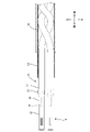
- FIG. 1 is an exploded perspective view of a shielded conductive path.
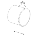
- FIG. 2 is a perspective view of the sleeve prior to being crimped onto the sheath.
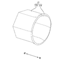
- FIG. 3 is a perspective view of the sleeve after being crimped to the sheath;
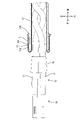
- FIG. 4 is a perspective view of the second outer conductor.
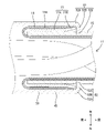
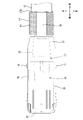
- FIG. 5 is a partial side cross-sectional view showing a state in which the rear crimping portion is crimped to the end of the shielded wire.
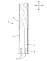
- FIG. 6 is a side cross-sectional view showing the end of the shielded wire that has been stripped.
- FIG. 7 is a side sectional view showing a state in which the female terminal is connected to the end of the covered electric wire.
- FIG. 1 is an exploded perspective view of a shielded conductive path.
- FIG. 2 is a perspective view of the sleeve prior to being crimped onto the sheath.
- FIG. 3 is a perspective
- FIG. 8 is a side cross-sectional view showing a state in which the sleeve is fitted over the end of the shielded wire and crimped, and the clip is attached to the end of the covered wire.
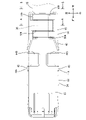
- FIG. 9 is a side view showing a state in which the dielectric attached to the female terminal is inserted into the rectangular tubular portion of the first outer conductor.
- FIG. 10 is a side view showing a state in which the second outer conductor is attached.
- 11 is a cross-sectional view taken along the line AA in FIG. 10.
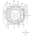
- FIG. 12 is a cross-sectional view taken along the line BB in FIG. 10.
- FIG. 13 is a partial side cross-sectional view showing another embodiment in which the rear crimping portion is crimped to the end of the shielded wire.
- FIG. 14 is a side sectional view showing another embodiment of the sleeve.
- the shielded conductive path of the present disclosure includes: (1) Equipped with a shield wire, a sleeve, and an outer conductor.
- the shielded wire has a shield layer surrounding the conductor and a sheath surrounding the shield layer, and the front end portion of the shield layer is folded back to form a folded portion covering the outer peripheral surface of the sheath.
- the sleeve is arranged in a gap between the outer peripheral surface of the sheath and the folded portion, and is crimped to the outer peripheral surface of the sheath.
- the outer conductor has a crimped portion formed at the rear end thereof.
- the crimping portion has a cylindrical crimping portion and a claw portion protruding radially inward from the rear end of the crimping portion in a cantilevered manner.
- the sleeve has a base and an extension extending rearwardly from a trailing edge of the base, the outer diameter of the trailing end of the extension being greater than the outer diameter of the base.
- the crimping portion is crimped to the sleeve in a state in which the crimp portion surrounds the folded portion and the claw portion faces the extending portion from behind. When the shielded wire is pulled rearward, the extension pushes the claw rearward.
- the extension pushes the pawl
- the moment of the force originating at the bent portion where the pawl and the crimping portion continue pushes the proximal end more than when the protruding end of the pawl is pushed. case is smaller.
- the extending portion pushes the proximal end portion of the claw portion, so there is no risk of the claw portion being deformed so as to open rearward. Therefore, according to the shielded conductive path of the present disclosure, the reliability of the anchoring function against tensile loads can be improved.
- the outer periphery of the rear end of the extending portion is in contact with the inner periphery of the crimped portion. According to this configuration, the position where the extension pushes the pawl can be set to the position closest to the crimping section, so that the reliability of the fixing function against the tensile load can be maximized.
- the outer peripheral edge of the rear end of the extending portion is circular and the rear end of the crimping portion is elliptical. According to this configuration, even if the crimping accuracy of the sleeve and the crimping portion are low, the portion of the crimping portion that continues to the short axis can be brought into contact with the outer peripheral edge of the extension portion.
- FIG. 1 A first embodiment embodying the present disclosure will be described with reference to FIGS. 1 to 12.
- FIG. 1 Regarding the front-rear direction, the downward direction in FIG. 1 is defined as the forward direction, and the upward direction is defined as the rearward direction.
- the left side in FIG. 1 is defined as the upper side, and the right side is defined as the lower side.
- the far side in FIG. 1 is defined as the right side, and the front side is defined as the left side.
- the shielded conductive path 10 includes a shielded wire 11, a sleeve 27, a female terminal 18, a dielectric 19, a first outer conductor 33, and a second outer conductor 34, which is an outer conductor.
- the shielded wire 11 is formed by surrounding the outer circumferences of two covered wires 13 with a braided wire 14 that is a shield layer made of thin metal wires, and by surrounding the outer circumference of the braided wire 14 with a sheath 15 .
- the two covered wires 13 are so-called twisted pair wires.
- Each covered electric wire 13 includes a core wire 16 that is a conductor and an insulating coating 17 that surrounds the core wire 16 . Copper, a copper alloy, aluminum, an aluminum alloy, or the like is used for the core wire 16 .
- the core wire 16 may be a single metal wire, or may be a twisted wire in which a plurality of metal wires are twisted together.
- the insulating coating 17 and the sheath 15 are made of insulating and flexible synthetic resin. Terminals of the shielded wire 11 are subjected to terminal treatment such as stripping, and respective terminals of the core wire 16, the insulating coating 17, and the braided wire 14 are exposed.
- the braided wire 14 is formed by braiding a plurality of thin metal wires into a tubular shape. A portion of the braided wire 14 that extends from the end of the sheath 15 and is exposed is folded back toward the end (rear) of the sheath 15 to form a folded portion 14A that covers the outer peripheral surface of the sheath 15 .
- the sleeve 27 is made of metal. As shown in FIGS. 2 and 3, the sleeve 27 has a base portion 27A and an extension portion 27B.
- the base portion 27A of the sleeve 27 has a cylindrical shape before being crimped to the terminal end of the sheath 15 (see FIG. 2).
- the extending portion 27B has a cylindrical shape communicating with the base portion 27A and extends rearward from the rear edge of the base portion 27A.
- the extending portion 27B expands in diameter in a funnel shape as it separates rearward from the base portion 27A.
- the sleeve 27 is crimped to the outer peripheral surface of the sheath 15, and then the exposed braided wire 14 is folded back so that the sheath 15 is inserted into the gap between the outer peripheral surface of the end of the sheath 15 and the folded portion 14A (braided wire 14). is arranged so as to cover the outer peripheral surface of the (see FIG. 8).
- the base portion 27A changes into a hexagonal shape in which six flat plates are arranged in a ring by being crimped to the end of the sheath 15 (see FIG. 3).
- the shape of the extending portion 27B gradually changes from a hexagonal shape to a circular shape as it moves away from the base portion 27A rearward.
- the outer diameter of the rear end of the extending portion 27B is larger than the outer diameter of the base portion 27A.
- the female terminal 18 is formed by pressing a metal plate into a predetermined shape.
- a metal such as copper, a copper alloy, aluminum, or an aluminum alloy is used for the female terminal 18 .
- the female terminal 18 is connected to the end of each covered wire 13 .
- the female terminal 18 has an insulation barrel 21 , a wire barrel 22 and a cylindrical portion 23 .
- the insulation barrel 21 is crimped so as to wrap around the outer periphery of the insulating coating 17 of the coated wire 13 .
- the wire barrel 22 is connected to the front of the insulation barrel 21 and crimped so as to wrap around the outer circumference of the core wire 16 .
- the cylindrical portion 23 continues in front of the wire barrel 22 and a mating terminal (not shown) is inserted therein.
- An elastic contact piece (not shown) is arranged in the cylindrical portion 23 . By inserting the mating terminal into the tubular portion 23 from the front, the mating terminal and the elastic contact piece are brought into elastic contact, and the mating terminal and the female terminal 18 are electrically connected.
- One clip 25 is attached to the two covered wires 13 led out from the end of the sheath 15 .
- the clip 25 is formed by pressing a metal plate into a predetermined shape. As shown in FIG. 1, the clip 25 is generally W-shaped when viewed from the front-rear direction.
- the clip 25 is crimped so as to wrap around the outer circumference of the insulating coating 17 of each coated wire 13 (see FIG. 8). By crimping the clip 25 onto the two covered wires 13, the relative positions of the two covered wires 13 are held.
- the dielectric 19 includes a lower dielectric 28 that opens upward and is arranged on the lower side, and an upper dielectric 29 that is attached to the lower dielectric 28 from above.
- the lower dielectric 28 and the upper dielectric 29 are made of insulating synthetic resin.
- the dielectric 19 is formed with a cavity extending in the front-rear direction in which the female terminal 18 is accommodated. In this embodiment, two cavities are formed side by side in the left-right direction.
- the first outer conductor 33 is formed by pressing a metal plate into a predetermined shape. Copper, a copper alloy, aluminum, an aluminum alloy, or the like is used for the first outer conductor 33 . As shown in FIG. 1 , the first outer conductor 33 has a square tubular portion 35 , a connection plate portion 36 and a first connecting portion 37 .
- the rectangular tubular portion 35 has a rectangular tubular shape extending in the front-rear direction.
- the connection plate portion 36 is provided behind the rectangular tubular portion 35, has a long and narrow plate shape extending in the front-rear direction, and is overlapped with the folded portion 14A from below.
- the first connecting portion 37 connects the rectangular tubular portion 35 and the connecting plate portion 36 in the front-rear direction.
- the inner shape of the rectangular tubular portion 35 is formed to be the same as or slightly larger than the outer shape of the dielectric 19 .
- the dielectric 19 is inserted into the rectangular tubular portion 35 from behind.
- Protrusions 43 are formed on the rear portions of the left and right walls of the rectangular tubular portion 35 so as to protrude outward in the left-right direction (see FIG. 9).
- the first connecting portion 37 extends obliquely downward and rearward from the lower side of the rear edge of the rectangular tubular portion 35 .
- the connecting plate portion 36 extends rearward from the center portion in the left-right direction of the rear edge of the first connecting portion 37 .
- the connection plate portion 36 has a plate shape elongated in the front-rear direction. A center portion in the left-right direction of the connection plate portion 36 is curved so as to swell downward from the front end to the rear end.
- the second outer conductor 34 is formed by pressing a metal plate into a predetermined shape. Copper, a copper alloy, aluminum, an aluminum alloy, or the like is used for the second outer conductor 34 .
- the second outer conductor 34 has a front crimp portion 44 , a rear crimp portion 45 that is a crimp portion, and a second connecting portion 46 .
- the front crimping portion 44 is positioned on the front side and crimped to the outer periphery of the rectangular tubular portion 35 (see FIG. 10).
- the rear crimping portion 45 is located on the rear side and crimps the folded portion 14A and the connecting plate portion 36 overlapping the folded portion 14A (see FIG. 11).
- the second connecting portion 46 connects the front crimping portion 44 and the rear crimping portion 45 .
- the left and right walls of the front crimping portion 44 hang down from the left and right edges of the upper wall that extends in the front-rear direction and the left-right direction. As shown in FIG. 4, a slit 44A is formed in the center of each of the left and right walls in the front-rear direction so as to be recessed upward.
- the lower end portions 44B of the left and right walls on the rear side of the slit 44A hang down as indicated by the two-dot chain line before they are assembled to the first outer conductor 33 . After each lower end portion 44B is attached to the first outer conductor 33, it is bent toward the center in the left-right direction so as to hold the first outer conductor 33 from below (see FIG. 10).
- a projecting portion 43 provided on the left wall of the rectangular tube portion 35 is fitted into the slit 44A on the left wall of the front crimping portion 44 (see FIG. 10).
- a projecting portion 43 provided on the right wall of the rectangular tubular portion 35 is fitted into the slit 44A on the right wall of the front crimping portion 44 (see FIG. 10).
- the second connecting portion 46 extends rearward from the rear edge of the front crimping portion 44 .
- a rear crimping portion 45 is provided at the rear end portion of the second outer conductor 34 and behind the second connecting portion 46 .
- the rear crimping portion 45 includes a crimping portion 50 extending rearward from the rear edge of the second connecting portion 46 and six claw portions 52 protruding radially inward from the rear end of the crimping portion 50 in a cantilevered manner. ,have.
- the crimping portion 50 has a shape curved upward when viewed from the front-rear direction.
- the crimping portion 50 has two right crimping pieces 50A and a left crimping piece 50B.
- the two right crimping pieces 50A are provided on the right edge of the crimping portion 50 so as to be spaced apart in the front-rear direction.
- One right crimping piece 50A is provided at each of the front end and the rear end of the right edge of the crimping portion 50 .
- locking parts are formed in the front-end
- the right engaging portion 50C is formed by folding the tip portion of the right crimping piece 50A inward in the left-right direction.
- the left crimping piece 50B is provided extending from the left end edge of the crimping portion 50 to the front-rear direction central portion.
- the width dimension in the front-rear direction of the left crimping piece 50B is set smaller than the interval in the front-rear direction between the pair of right crimping pieces 50A.
- a left engaging portion 50D is formed at the tip of the left crimping piece 50B.
- the left engaging portion 50D is formed by folding the tip portion of the left crimping piece 50B inward in the left-right direction.
- the left crimping piece 50B hangs down as indicated by the chain double-dashed line before it is crimped onto the shielded wire 11 .
- the left crimping piece 50B After being crimped onto the shielded wire 11, the left crimping piece 50B is deformed into a curved shape along the outer peripheral surface of the shielded wire 11 so as to hold the shielded wire 11 from below (see FIG. 11). .
- the left crimping piece 50B is arranged between the two right crimping pieces 50A.
- the crimping portion 50, the right crimping piece 50A, and the left crimping piece 50B are crimped to the end of the shielded wire 11 to change into an elliptical cylindrical shape with a minor axis in the vertical direction (FIGS. 11 and 11). 12).
- the six claw portions 52 are provided along the rear edge of the crimping portion 50 so as to be separated from each other. These claw portions 52 form a substantially right angle from the rear end edge of the crimped portion 50 toward the inside of the shielded wire 11 in the radial direction when the crimped portion 50 is crimped to the end of the shielded wire 11 . It is bent like this (see Fig. 5). The rear end of the crimping portion 50 and the base end portion 52B of the claw portion 52 are connected to form a right angle via the bent portion 52A. The distal end portion 52C of the claw portion 52 is located radially inside the shielded wire 11 relative to the bent portion 52A and the proximal end portion 52B.
- the tips 52C of the claws 52 bite into the outer periphery of the sheath 15 (see FIG. 5).
- the claw portion 52 is attached to the rear end of the extension portion 27B of the sleeve 27. They are arranged so as to face and contact from the rear (see FIG. 5).
- the right locking portion 50C is positioned at the left edge of the connection plate portion 36. , facing each other from the left (see FIG. 11).
- the left engaging portion 50D faces the right edge of the connecting plate portion 36 from the right side with a slight gap therebetween (see FIG. 11).
- the sheath 15 is removed in a predetermined range. This exposes the braided wire 14 in the area where the sheath 15 has been removed. Then, in the exposed braided wire 14, the braided wire 14 is cut in a predetermined area to expose the coated wire 13. As shown in FIG. Then, the insulating coating 17 is removed in a predetermined range from the terminal portion of the covered electric wire 13 . Thereby, the core wire 16 is exposed in the region where the insulating coating 17 is removed.
- the wire barrel 22 of the female terminal 18 is crimped onto the outer circumference of the core wire 16 and the insulation barrel 21 of the female terminal 18 is crimped onto the outer circumference of the insulation coating 17 .
- the female terminal 18 is connected to the end of the covered wire 13 .
- the sleeve 27 is fitted over the end of the sheath 15 .
- the sleeve 27 is externally fitted over the end of the sheath 15 with the extending portion 27B facing backward from the base portion 27A.
- the base portion 27A of the sleeve 27 is caulked to the sheath 15.
- the outer shape of the base portion 27A changes from a cylindrical shape to a hexagonal shape (see FIGS. 2 and 3).
- the braided wire 14 exposed from the end of the sheath 15 is folded back to form a folded portion 14A covering the outer peripheral surface of the sleeve 27 .
- the front end of the base portion 27A of the sleeve 27 inserted over the sheath 15 is located slightly behind the front end of the sheath 15.
- clips 25 are attached to the two coated wires 13 .
- the female terminal 18 is arranged in the upper dielectric 29 and the lower dielectric 28 is assembled with the upper dielectric 29 .
- the dielectric 19 is inserted from behind into the rectangular tubular portion 35 of the first outer conductor 33 (see FIG. 9).
- the connection plate portion 36 of the first outer conductor 33 is overlapped under the folded portion 14A (see FIG. 9).
- each slit 44 ⁇ /b>A of the second outer conductor 34 is fitted to each projecting portion 43 of the square tubular portion 35 .
- the lower end portion 44B of the front crimping portion 44 is bent toward the center in the left-right direction and crimped to the outer periphery of the rectangular tube portion 35, and the rear crimping portion 45 (the crimping portion 50, the right crimping piece 50A, the left crimping piece 50B). ) are crimped to the outer periphery of the folded portion 14A (braided wire 14) and the connecting plate portion 36.
- the right crimping piece 50A and the left crimping piece 50B are crimped so as to wrap around the outer periphery of the folded portion 14A and the connection plate portion 36.
- the left engaging portion 50D of the left crimping piece 50B is engaged with the right edge of the connecting plate portion 36 from the right side
- the right engaging portion 50C of the right crimping piece 50A is engaged with the left edge of the connecting plate portion 36 from the left side. lock from the side. This suppresses the expansion and deformation of the rear crimping portion 45 .
- the crimping portion 50, the right crimping piece 50A, and the left crimping piece 50B of the rear crimping portion 45 are crimped to the sleeve 27 so as to surround the folded portion 14A.
- the braided wire 14, the first outer conductor 33, and the second outer conductor 34 are electrically connected by crimping the rear crimping portion 45 to the folded portion 14A and the connection plate portion 36.
- the thin metal wires forming the folded portion 14A move away from the corners of the hexagonal base portion 27A, and are concentrated at the central portion of each side.
- the assembly of the shield conductive path 10 is completed.
- the outer peripheral edge of the rear end of the extending portion 27B of the sleeve 27 has a circular shape.
- the crimping portion 50 at the rear end portion of the rear crimping portion 45, the right crimping piece 50A, and the left crimping piece 50B form an elliptical tubular shape with a minor axis extending in the vertical direction.
- the distal end portion 52C of the claw portion 52 of the rear crimping portion 45 is in a state of biting into the outer circumference of the sheath 15 .
- the base end portion 52B of the claw portion 52 is in contact with the rear end of the extension portion 27B of the sleeve 27 facing from behind. Furthermore, the folded portion 14A (braided wire 14) is not interposed between the outer peripheral edge of the rear end portion of the extending portion 27B having the largest outer diameter and the inner surface of the crimp portion 50. As shown in FIG. The outer peripheral edge of the extending portion 27B is in contact with the inner periphery of the left-right central portion of the upper end portion of the crimping portion 50 (see FIG. 12). As a result, even when the shielded wire 11 is pulled rearward, the claw portion 52 is prevented from being deformed so as to expand rearward.
- the shielded conductive path 10 of the present disclosure includes a shielded wire 11, a sleeve 27, and a second outer conductor 34.
- the shielded wire 11 has a braided wire 14 surrounding a core wire 16 and a sheath 15 surrounding the braided wire 14.
- a folded portion covers the outer peripheral surface of the sheath 15 by folding back the front end portion of the braided wire 14.
- 14A is formed.
- the sleeve 27 is arranged in a gap between the outer peripheral surface of the sheath 15 and the folded portion 14A and is crimped to the outer peripheral surface of the sheath 15 .
- a rear crimping portion 45 is formed at the rear end portion of the second outer conductor 34 .
- the rear crimping portion 45 has a cylindrical crimping portion 50 and a claw portion 52 protruding radially inward from the rear end of the crimping portion 50 in a cantilevered manner.
- the sleeve 27 has a tubular base portion 27A and an extension portion 27B extending rearward from the rear edge of the base portion 27A.
- the outer diameter of the rear end of the extending portion 27B is larger than the outer diameter of the base portion 27A.
- the rear crimping portion 45 is crimped to the sleeve 27 with the crimping portion 50 surrounding the folded portion 14A and the claw portion 52 facing the extending portion 27B from behind.
- the extending portion 27B pushes the claw portion 52 rearward.
- the moment of force originating from the bent portion 52A where the claw portion 52 and the crimping portion 50 continue is greater than when the tip portion 52C of the claw portion 52 is pushed. It is smaller when the base end portion 52B is pushed.
- the extending portion 27B pushes the base end portion 52B of the claw portion 52, so there is no possibility that the claw portion 52 is deformed so as to open rearward. Therefore, according to the shielded conductive path 10 of the present disclosure, it is possible to improve the reliability of the fixing function against the tensile load.
- the outer periphery of the rear end of the extending portion 27B of the shield conductive path 10 of the present disclosure is in contact with the inner periphery of the crimping portion 50.
- the position where the extension 27B presses the claw 52 can be set to the position closest to the inner peripheral surface of the crimping portion 50 (that is, the base end 52B), so that the fixation against the tensile load can be prevented. Functionality can be most reliable.
- the outer periphery of the rear end of the extending portion 27B of the shield conductive path 10 of the present disclosure has a circular shape, and the rear end portion of the rear crimping portion 45 has an elliptical shape. According to this configuration, even if the crimping accuracy of the sleeve 27 and the crimping accuracy of the rear crimping portion 45 are low, the portion of the crimping portion 50 connected to the short axis is brought into contact with the outer peripheral edge of the extension portion 27B. can be brought into contact.
- the folded portion 14A is partially crushed and sandwiched between the outer peripheral surface of the extending portion 27B and the inner peripheral surface of the crimping portion 50. may This configuration can prevent positional deviation between the sleeve 27 and the folded portion 14A.
- the shield layer is a braided wire in the above embodiment, the shield layer is not limited to a braided wire, and may be a metal foil or the like.
- the outer peripheral edge of the rear end of the extension is circular, and the rear end of the crimping portion is elliptical. Both ends may be circular.
- a twisted pair electric wire is used as the shield electric wire in the above embodiment, it may be a coaxial cable.
- the sleeve may have a slit extending from one axial end to the other axial end. Also, as in a sleeve 127 shown in FIG. 14, the outer diameter from the front end to the rear end of the extending portion 127B may be larger than that of the base portion 127A.
Landscapes
- Connections Effected By Soldering, Adhesion, Or Permanent Deformation (AREA)
- Details Of Connecting Devices For Male And Female Coupling (AREA)
Priority Applications (2)
| Application Number | Priority Date | Filing Date | Title |
|---|---|---|---|
| US18/576,099 US20240313483A1 (en) | 2021-07-07 | 2022-07-04 | Shielded electrically conductive path |
| CN202280045231.7A CN117561654A (zh) | 2021-07-07 | 2022-07-04 | 屏蔽导电路径 |
Applications Claiming Priority (2)
| Application Number | Priority Date | Filing Date | Title |
|---|---|---|---|
| JP2021112602A JP7533384B2 (ja) | 2021-07-07 | 2021-07-07 | シールド導電路 |
| JP2021-112602 | 2021-07-07 |
Publications (1)
| Publication Number | Publication Date |
|---|---|
| WO2023282225A1 true WO2023282225A1 (ja) | 2023-01-12 |
Family
ID=84800697
Family Applications (1)
| Application Number | Title | Priority Date | Filing Date |
|---|---|---|---|
| PCT/JP2022/026570 Ceased WO2023282225A1 (ja) | 2021-07-07 | 2022-07-04 | シールド導電路 |
Country Status (4)
| Country | Link |
|---|---|
| US (1) | US20240313483A1 (https=) |
| JP (1) | JP7533384B2 (https=) |
| CN (1) | CN117561654A (https=) |
| WO (1) | WO2023282225A1 (https=) |
Cited By (2)
| Publication number | Priority date | Publication date | Assignee | Title |
|---|---|---|---|---|
| WO2023218871A1 (ja) * | 2022-05-09 | 2023-11-16 | 株式会社オートネットワーク技術研究所 | 電線と外導体との圧着構造 |
| WO2023233938A1 (ja) * | 2022-05-30 | 2023-12-07 | 株式会社オートネットワーク技術研究所 | 電線と外導体との圧着構造 |
Families Citing this family (1)
| Publication number | Priority date | Publication date | Assignee | Title |
|---|---|---|---|---|
| JP7552490B2 (ja) * | 2021-04-19 | 2024-09-18 | 株式会社オートネットワーク技術研究所 | ケーブル付きコネクタ |
Citations (4)
| Publication number | Priority date | Publication date | Assignee | Title |
|---|---|---|---|---|
| JP2010182647A (ja) * | 2009-02-09 | 2010-08-19 | Sumitomo Wiring Syst Ltd | シールドコネクタ及びシールドシェル |
| JP2020057493A (ja) * | 2018-10-01 | 2020-04-09 | 矢崎総業株式会社 | シールド電線の端子接続構造 |
| JP2020107563A (ja) * | 2018-12-28 | 2020-07-09 | 株式会社オートネットワーク技術研究所 | コネクタ、及びコネクタ構造体 |
| WO2021029201A1 (ja) * | 2019-08-09 | 2021-02-18 | 株式会社オートネットワーク技術研究所 | ケーブル付きコネクタ |
Family Cites Families (13)
| Publication number | Priority date | Publication date | Assignee | Title |
|---|---|---|---|---|
| US3670293A (en) * | 1970-08-20 | 1972-06-13 | Amp Inc | Shielded wire connectors |
| US5246384A (en) * | 1990-03-15 | 1993-09-21 | Hirose Electric Co., Ltd. | Shielded cable board-in connector |
| US6059607A (en) * | 1998-03-17 | 2000-05-09 | Molex Incorporated | Shielded electrical connector |
| US7422480B1 (en) * | 2007-04-20 | 2008-09-09 | Delphi Technologies, Inc. | Shielded electric connector and cable assembly and method for making same |
| US9960504B2 (en) * | 2016-01-12 | 2018-05-01 | Yazaki Corporation | Shielded connector |
| JP6745044B2 (ja) * | 2017-02-03 | 2020-08-26 | 株式会社オートネットワーク技術研究所 | シールド端子 |
| JP6780546B2 (ja) * | 2017-03-01 | 2020-11-04 | 株式会社オートネットワーク技術研究所 | 端子付きシールド電線 |
| JP6939529B2 (ja) * | 2017-12-26 | 2021-09-22 | 住友電装株式会社 | 端子金具 |
| JP6939531B2 (ja) * | 2017-12-26 | 2021-09-22 | 住友電装株式会社 | 端子金具 |
| US10741975B2 (en) * | 2018-10-19 | 2020-08-11 | Aptiv Technologies Limited | Sheilded cable assembly and electromagnetic shield terminal assembly for same |
| JP7103204B2 (ja) * | 2018-12-21 | 2022-07-20 | 株式会社オートネットワーク技術研究所 | コネクタ構造体 |
| JP7380420B2 (ja) * | 2020-05-27 | 2023-11-15 | 株式会社オートネットワーク技術研究所 | シールド導電路 |
| JP2023077165A (ja) * | 2021-11-24 | 2023-06-05 | 住友電装株式会社 | シールド端子とシールド電線の接続構造 |
-
2021
- 2021-07-07 JP JP2021112602A patent/JP7533384B2/ja active Active
-
2022
- 2022-07-04 CN CN202280045231.7A patent/CN117561654A/zh active Pending
- 2022-07-04 US US18/576,099 patent/US20240313483A1/en active Pending
- 2022-07-04 WO PCT/JP2022/026570 patent/WO2023282225A1/ja not_active Ceased
Patent Citations (4)
| Publication number | Priority date | Publication date | Assignee | Title |
|---|---|---|---|---|
| JP2010182647A (ja) * | 2009-02-09 | 2010-08-19 | Sumitomo Wiring Syst Ltd | シールドコネクタ及びシールドシェル |
| JP2020057493A (ja) * | 2018-10-01 | 2020-04-09 | 矢崎総業株式会社 | シールド電線の端子接続構造 |
| JP2020107563A (ja) * | 2018-12-28 | 2020-07-09 | 株式会社オートネットワーク技術研究所 | コネクタ、及びコネクタ構造体 |
| WO2021029201A1 (ja) * | 2019-08-09 | 2021-02-18 | 株式会社オートネットワーク技術研究所 | ケーブル付きコネクタ |
Cited By (6)
| Publication number | Priority date | Publication date | Assignee | Title |
|---|---|---|---|---|
| WO2023218871A1 (ja) * | 2022-05-09 | 2023-11-16 | 株式会社オートネットワーク技術研究所 | 電線と外導体との圧着構造 |
| JP2023166175A (ja) * | 2022-05-09 | 2023-11-21 | 株式会社オートネットワーク技術研究所 | 電線と外導体との圧着構造 |
| JP7679796B2 (ja) | 2022-05-09 | 2025-05-20 | 株式会社オートネットワーク技術研究所 | 電線と外導体との圧着構造 |
| WO2023233938A1 (ja) * | 2022-05-30 | 2023-12-07 | 株式会社オートネットワーク技術研究所 | 電線と外導体との圧着構造 |
| JP2023175333A (ja) * | 2022-05-30 | 2023-12-12 | 株式会社オートネットワーク技術研究所 | 電線と外導体との圧着構造 |
| JP7737613B2 (ja) | 2022-05-30 | 2025-09-11 | 株式会社オートネットワーク技術研究所 | 電線と外導体との圧着構造 |
Also Published As
| Publication number | Publication date |
|---|---|
| JP7533384B2 (ja) | 2024-08-14 |
| JP2023009381A (ja) | 2023-01-20 |
| US20240313483A1 (en) | 2024-09-19 |
| CN117561654A (zh) | 2024-02-13 |
Similar Documents
| Publication | Publication Date | Title |
|---|---|---|
| EP2254203B1 (en) | Resilient plug, fluid proof construction and connector | |
| WO2023282225A1 (ja) | シールド導電路 | |
| JP7240607B2 (ja) | ケーブル付きコネクタ | |
| JP3421555B2 (ja) | 同軸ケーブル用コネクタの接続構造及びその接続方法 | |
| US11133606B2 (en) | Wire crimping structure and shielded conductive path | |
| JP7109351B2 (ja) | コネクタ端子 | |
| JP5343885B2 (ja) | 防水機能付き端子金具及び防水コネクタ | |
| JPH08250218A (ja) | シールド線のシースずれ防止構造 | |
| JP5195244B2 (ja) | 端子金具及び端子金具付き電線 | |
| JP2020057493A (ja) | シールド電線の端子接続構造 | |
| JP7129010B2 (ja) | コネクタ構造体 | |
| JP5913194B2 (ja) | コネクタ | |
| CN113196589A (zh) | 连接器结构体及连接器结构体的制造方法 | |
| JP7406711B2 (ja) | シールド導電路 | |
| JP5772386B2 (ja) | シールド部材及びシールド導電体 | |
| JP4392381B2 (ja) | シールドコネクタ | |
| WO2023218871A1 (ja) | 電線と外導体との圧着構造 | |
| JP3419638B2 (ja) | シールドコネクタ | |
| JPH1140274A (ja) | シールドコネクタ | |
| JP3386384B2 (ja) | シールド電線の端末処理構造 | |
| JP4868458B2 (ja) | シールド電線の端子接続構造 | |
| JP5344899B2 (ja) | 同軸ケーブル用コネクタ | |
| JP7737613B2 (ja) | 電線と外導体との圧着構造 | |
| JPH1140273A (ja) | シールドコネクタ | |
| JP2025162254A (ja) | 高周波コネクタ及びケーブル付き高周波コネクタ |
Legal Events
| Date | Code | Title | Description |
|---|---|---|---|
| 121 | Ep: the epo has been informed by wipo that ep was designated in this application |
Ref document number: 22835550 Country of ref document: EP Kind code of ref document: A1 |
|
| WWE | Wipo information: entry into national phase |
Ref document number: 202280045231.7 Country of ref document: CN |
|
| NENP | Non-entry into the national phase |
Ref country code: DE |
|
| 122 | Ep: pct application non-entry in european phase |
Ref document number: 22835550 Country of ref document: EP Kind code of ref document: A1 |