WO2023276385A1 - タービン静翼、及び蒸気タービン - Google Patents
タービン静翼、及び蒸気タービン Download PDFInfo
- Publication number
- WO2023276385A1 WO2023276385A1 PCT/JP2022/015932 JP2022015932W WO2023276385A1 WO 2023276385 A1 WO2023276385 A1 WO 2023276385A1 JP 2022015932 W JP2022015932 W JP 2022015932W WO 2023276385 A1 WO2023276385 A1 WO 2023276385A1
- Authority
- WO
- WIPO (PCT)
- Prior art keywords
- turbine
- fine grooves
- stator vane
- steam
- extending
- Prior art date
Links
- 239000007788 liquid Substances 0.000 claims abstract description 25
- 238000011144 upstream manufacturing Methods 0.000 claims abstract description 21
- 238000011084 recovery Methods 0.000 claims abstract description 17
- 230000002093 peripheral effect Effects 0.000 claims description 31
- 230000007423 decrease Effects 0.000 claims description 8
- 230000003628 erosive effect Effects 0.000 description 5
- 238000013459 approach Methods 0.000 description 3
- 238000012986 modification Methods 0.000 description 3
- 230000004048 modification Effects 0.000 description 3
- 238000010586 diagram Methods 0.000 description 2
- 238000000034 method Methods 0.000 description 2
- 230000000694 effects Effects 0.000 description 1
- 238000010248 power generation Methods 0.000 description 1
- 230000001105 regulatory effect Effects 0.000 description 1
- 230000003068 static effect Effects 0.000 description 1
- 230000005514 two-phase flow Effects 0.000 description 1
- XLYOFNOQVPJJNP-UHFFFAOYSA-N water Substances O XLYOFNOQVPJJNP-UHFFFAOYSA-N 0.000 description 1
Images


Classifications
-
- F—MECHANICAL ENGINEERING; LIGHTING; HEATING; WEAPONS; BLASTING
- F01—MACHINES OR ENGINES IN GENERAL; ENGINE PLANTS IN GENERAL; STEAM ENGINES
- F01D—NON-POSITIVE DISPLACEMENT MACHINES OR ENGINES, e.g. STEAM TURBINES
- F01D9/00—Stators
- F01D9/02—Nozzles; Nozzle boxes; Stator blades; Guide conduits, e.g. individual nozzles
-
- F—MECHANICAL ENGINEERING; LIGHTING; HEATING; WEAPONS; BLASTING
- F01—MACHINES OR ENGINES IN GENERAL; ENGINE PLANTS IN GENERAL; STEAM ENGINES
- F01D—NON-POSITIVE DISPLACEMENT MACHINES OR ENGINES, e.g. STEAM TURBINES
- F01D25/00—Component parts, details, or accessories, not provided for in, or of interest apart from, other groups
- F01D25/32—Collecting of condensation water; Drainage ; Removing solid particles
-
- F—MECHANICAL ENGINEERING; LIGHTING; HEATING; WEAPONS; BLASTING
- F01—MACHINES OR ENGINES IN GENERAL; ENGINE PLANTS IN GENERAL; STEAM ENGINES
- F01D—NON-POSITIVE DISPLACEMENT MACHINES OR ENGINES, e.g. STEAM TURBINES
- F01D5/00—Blades; Blade-carrying members; Heating, heat-insulating, cooling or antivibration means on the blades or the members
- F01D5/12—Blades
- F01D5/14—Form or construction
- F01D5/147—Construction, i.e. structural features, e.g. of weight-saving hollow blades
-
- F—MECHANICAL ENGINEERING; LIGHTING; HEATING; WEAPONS; BLASTING
- F05—INDEXING SCHEMES RELATING TO ENGINES OR PUMPS IN VARIOUS SUBCLASSES OF CLASSES F01-F04
- F05D—INDEXING SCHEME FOR ASPECTS RELATING TO NON-POSITIVE-DISPLACEMENT MACHINES OR ENGINES, GAS-TURBINES OR JET-PROPULSION PLANTS
- F05D2220/00—Application
- F05D2220/30—Application in turbines
- F05D2220/31—Application in turbines in steam turbines
-
- F—MECHANICAL ENGINEERING; LIGHTING; HEATING; WEAPONS; BLASTING
- F05—INDEXING SCHEMES RELATING TO ENGINES OR PUMPS IN VARIOUS SUBCLASSES OF CLASSES F01-F04
- F05D—INDEXING SCHEME FOR ASPECTS RELATING TO NON-POSITIVE-DISPLACEMENT MACHINES OR ENGINES, GAS-TURBINES OR JET-PROPULSION PLANTS
- F05D2250/00—Geometry
- F05D2250/10—Two-dimensional
- F05D2250/11—Two-dimensional triangular
-
- F—MECHANICAL ENGINEERING; LIGHTING; HEATING; WEAPONS; BLASTING
- F05—INDEXING SCHEMES RELATING TO ENGINES OR PUMPS IN VARIOUS SUBCLASSES OF CLASSES F01-F04
- F05D—INDEXING SCHEME FOR ASPECTS RELATING TO NON-POSITIVE-DISPLACEMENT MACHINES OR ENGINES, GAS-TURBINES OR JET-PROPULSION PLANTS
- F05D2250/00—Geometry
- F05D2250/10—Two-dimensional
- F05D2250/13—Two-dimensional trapezoidal
-
- F—MECHANICAL ENGINEERING; LIGHTING; HEATING; WEAPONS; BLASTING
- F05—INDEXING SCHEMES RELATING TO ENGINES OR PUMPS IN VARIOUS SUBCLASSES OF CLASSES F01-F04
- F05D—INDEXING SCHEME FOR ASPECTS RELATING TO NON-POSITIVE-DISPLACEMENT MACHINES OR ENGINES, GAS-TURBINES OR JET-PROPULSION PLANTS
- F05D2250/00—Geometry
- F05D2250/10—Two-dimensional
- F05D2250/14—Two-dimensional elliptical
- F05D2250/141—Two-dimensional elliptical circular
-
- F—MECHANICAL ENGINEERING; LIGHTING; HEATING; WEAPONS; BLASTING
- F05—INDEXING SCHEMES RELATING TO ENGINES OR PUMPS IN VARIOUS SUBCLASSES OF CLASSES F01-F04
- F05D—INDEXING SCHEME FOR ASPECTS RELATING TO NON-POSITIVE-DISPLACEMENT MACHINES OR ENGINES, GAS-TURBINES OR JET-PROPULSION PLANTS
- F05D2250/00—Geometry
- F05D2250/20—Three-dimensional
- F05D2250/29—Three-dimensional machined; miscellaneous
- F05D2250/294—Three-dimensional machined; miscellaneous grooved
-
- F—MECHANICAL ENGINEERING; LIGHTING; HEATING; WEAPONS; BLASTING
- F05—INDEXING SCHEMES RELATING TO ENGINES OR PUMPS IN VARIOUS SUBCLASSES OF CLASSES F01-F04
- F05D—INDEXING SCHEME FOR ASPECTS RELATING TO NON-POSITIVE-DISPLACEMENT MACHINES OR ENGINES, GAS-TURBINES OR JET-PROPULSION PLANTS
- F05D2250/00—Geometry
- F05D2250/30—Arrangement of components
- F05D2250/32—Arrangement of components according to their shape
- F05D2250/323—Arrangement of components according to their shape convergent
Definitions
- a steam turbine includes a rotating shaft rotatable around an axis, a plurality of turbine rotor blade rows arranged at intervals in the axial direction on the outer peripheral surface of the rotating shaft, the rotating shaft, and the turbine rotor blade rows arranged on the outer circumference. and a plurality of rows of turbine stator blades radially supported by an inner ring and an outer ring on the inner peripheral side of the casing.
- Each turbine rotor blade row has a plurality of rotor blades arranged in the circumferential direction of the rotating shaft, and each turbine stator blade row has a plurality of stator blades arranged in the circumferential direction of the rotating shaft.
- the turbine rotor blade row forms one stage by being arranged adjacent to the turbine stator blade row on the downstream side in the axial direction.
- a suction port connected to an inlet pipe for taking in steam from the outside is formed on the upstream side of the casing, and an exhaust chamber is formed on the downstream side.
- the steam generated in the boiler has its pressure and temperature adjusted by the control valve, and its flow rate adjusted by the turbine inlet valve before flowing into the turbine.
- the high-temperature, high-pressure steam taken in from the inlet pipe is converted to rotational force of the rotating shaft by the turbine rotor blade row after the flow direction and speed are adjusted by the turbine stator blade row.
- steam turbines for thermal power generation generally consist of a high pressure turbine, an intermediate pressure turbine and a low pressure turbine.
- a gas-liquid two-phase flow environment exists in two stages (a pair of a turbine stator blade row and a turbine rotor blade row) counted from the most downstream side of the low-pressure turbine. Therefore, in the most downstream stage, part of the steam is liquefied and exists as fine droplets (water droplets) in the airflow, and some of the droplets adhere to the surface of the turbine stationary blade.
- one guide groove is formed on the surface of the turbine rotor blade. It is said that by guiding the liquid droplets along the guide grooves, it is possible to prevent the liquid droplets from flowing to the tip side of the turbine rotor blade, which has a high peripheral speed.
- the present disclosure has been made to solve the above problems, and an object thereof is to provide a turbine stator vane and a steam turbine capable of suppressing or collecting droplets more efficiently.
- a turbine stator vane includes a stator vane body extending in a radial direction that intersects the flow direction of steam, and a liquid flow path formed on the surface of the stator vane body and flowing along the surface. a recovery section for recovering the film; and a central region formed on the surface of the stationary blade main body and formed with a plurality of first fine grooves extending from the upstream side in the flow direction toward the recovery section. The interval between the first fine grooves adjacent to each other becomes narrower toward the collecting portion from the side.
- FIG. 1 is a cross-sectional view showing the configuration of a steam turbine according to an embodiment of the present disclosure
- FIG. 1 is an enlarged cross-sectional view of a main part of a steam turbine according to an embodiment of the present disclosure
- FIG. FIG. 4 is a cross-sectional view showing the shape of fine grooves according to an embodiment of the present disclosure
- FIG. 4 is a diagram showing a first modified example of a turbine stator vane according to an embodiment of the present disclosure
- FIG. 5 is a diagram showing a second modified example of a turbine stator vane according to an embodiment of the present disclosure
- FIG. 4 is a cross-sectional view showing a first modified example of fine grooves according to an embodiment of the present disclosure
- FIG. 5 is a cross-sectional view showing a second modified example of fine grooves according to an embodiment of the present disclosure
- FIG. 5 is a cross-sectional view showing a third modified example of fine grooves according to an embodiment of the present disclosure
- FIG. 11 is a cross-sectional view showing a fourth modified example of fine grooves according to an embodiment of the present disclosure
- the steam turbine 1 includes a rotor 2 and a casing 3.
- the rotor 2 has a rotating shaft 6 with a circular cross section extending along the axis O and a plurality of rotor blade cascades 7 provided on the outer peripheral surface of the rotating shaft 6 .
- the rotary shaft 6 is rotatable around the axis O.
- a plurality of rotor blade cascades 7 are arranged at intervals in the axis O direction.
- Each moving blade cascade 7 has a plurality of moving blades 8 arranged in the circumferential direction of the axis O.
- the rotor blades 8 extend radially outward from the outer peripheral surface of the rotating shaft 6 . A detailed configuration of the rotor blade 8 will be described later.
- the casing 3 is supported from the outer peripheral side and the inner peripheral side by a casing main body 3H that covers the rotor 2 from the outer peripheral side, and an outer ring 21 (described later) and an inner ring 23 (described later) provided on the inner peripheral side of the casing main body 3H. and a plurality of stator blade cascades 9 that are arranged.
- the casing main body 3H has a cylindrical shape centered on the axis O. As shown in FIG.
- the plurality of stator blade cascades 9 are arranged at intervals in the axis O direction.
- the steam turbine 1 has the same number of rotor blade cascades 7 as the stator blade cascades 9, and one rotor blade cascade 7 is positioned between a pair of stator blade cascades 9 adjacent to each other in the axis O direction. That is, the moving blade cascades 7 and the stationary blade cascades 9 are alternately arranged in the axis O direction.
- One stator blade cascade 9 and one rotor blade cascade 7 form one "stage".
- Each stationary blade cascade 9 has a plurality of stationary blades 10 arranged in the circumferential direction of the axis O. As shown in FIG.
- the stationary blade 10 extends radially with respect to the axis O. As shown in FIG.
- a steam passage 11 is formed on one side of the casing main body 3H in the direction of the axis O to take in the high-temperature, high-pressure steam guided from the inlet pipe into the section of the casing main body 3H.
- An exhaust chamber 12 that recovers the pressure of the steam is provided on the other side of the casing body 3H in the direction of the axis O. As shown in FIG.
- the steam that has flowed into the steam flow path 11 flows through the stages in the casing body 3H, then passes through the exhaust chamber 12 and is sent to the condenser (not shown).
- the side on which the steam flow path 11 is located as viewed from the exhaust chamber 12 is referred to as the upstream side in the steam flow direction.
- the side on which the exhaust chamber 12 is located when viewed from the steam flow path 11 is called the downstream side.
- the rotor blade 8 has a platform 81 , a rotor blade body 82 and a shroud 83 .
- the platform 81 is installed on the outer peripheral surface of the rotating shaft 6 (rotating shaft outer peripheral surface 6A).
- a moving blade main body 82 is provided on the outer peripheral side of the platform 81 .
- the rotor blade main body 82 extends in the radial direction and has an airfoil cross-sectional shape when viewed in the radial direction.
- the rotor blade body 82 is formed so that the dimension in the direction of the axis O gradually decreases from the radially inner side to the outer side.
- a shroud 83 is provided at the radially outer end of the moving blade main body 82 .
- the shroud 83 has a substantially rectangular cross-sectional shape whose longitudinal direction is the direction of the axis O. As shown in FIG.
- the outer peripheral surface of the shroud 83 faces the inner peripheral surface of the casing main body 3H (3A of the casing inner peripheral surface) with a gap in the radial direction.
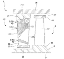
- the stationary blade 10 has an outer ring 21 , a stationary blade main body 22 (blade main body), and an inner ring 23 .
- the stator blade main body 22 also has a central region 41, an outer region 42, an inner region 43, and a slit 13 (recovery portion 14).
- the outer ring 21 has an annular shape centered on the axis O. As shown in FIG. The outer ring 21 is supported by the casing main body 3H via a support member (not shown).
- the stationary blade body 22 is fixed between the outer ring 21 and the inner ring 23 .
- the stator vane main body 22 extends radially inward from the outer ring inner peripheral surface 21A and has an airfoil cross-sectional shape when viewed in the radial direction.
- the stationary blade main body 22 extends in a direction intersecting the steam flow direction.
- the stator vane main body 22 gradually decreases in dimension in the direction of the axis O from the radially outer side to the inner side.
- An inner ring 23 is provided at the radially inner end of the stationary blade main body 22 .
- the inner ring 23 has a substantially rectangular cross-sectional shape whose longitudinal direction is the direction of the axis O. As shown in FIG.
- the inner peripheral surface of the inner ring 23 faces the rotating shaft outer peripheral surface 6A with a gap in the radial direction.
- the surface of the stator vane body 22 (more specifically, of the two surfaces in the thickness direction of the stator vane body 22 , the surface facing the upstream side: ventral surface) has a central region 41 , an outer region 42 , and an inner region 43 . and a slit 13 are formed.
- a plurality of fine grooves 5 recessed inward from the surface of the stationary blade main body 22 are formed in the central region 41 , the outer region 42 , and the inner region 43 .
- the fine grooves 5 are provided to transport droplets generated on the surface of the stationary blade main body 22 to the downstream side along the steam flow.
- the fine grooves 5 are arranged at intervals in the radial direction.
- the fine grooves 5 (first fine grooves 51) formed in the central region 41 are spaced apart from the first fine grooves 51 adjacent to each other as they go from the leading edge 22a side to the trailing edge 22b side of the stationary blade main body 22. is narrowed. That is, the central region 41 gradually decreases in radial dimension from the front edge 22a side toward the rear edge 22b side.
- the downstream end portions of the first fine grooves 51 communicate with the slits 13 to be described later.
- the outer region 42 is formed radially outward of the central region 41 .
- the fine grooves 5 (second fine grooves 52) formed in the outer region 42 are curved radially outward from the front edge 22a toward the downstream side. A downstream end of the second fine groove 52 is connected to the inner peripheral surface of the outer ring 21 .
- the inner region 43 is formed radially inward of the central region 41 .
- the fine grooves 5 (third fine grooves 53) formed in the inner region 43 are curved radially inward from the front edge 22a toward the downstream side.
- the downstream end of the third fine groove 53 extends to a radially inner region (near the inner ring 23) of the trailing edge 22b.
- the central region 41 (first fine groove 51) occupies the largest proportion, and the outer region 42 and the inner region 43 occupy a smaller area than the central region 41.
- a slit 13 is formed as a recovery portion 14 for recovering the liquid film flowing through the first fine groove 51 on the side of the trailing edge 22b in the central region 41 described above.
- the slit 13 extends along the trailing edge 22b.
- the slit 13 is one or more elongated holes that communicate with the interior of the stationary blade main body 22 . That is, the stationary blade body 22 is hollow.
- the internal space of the stationary blade main body 22 is desirably brought into a negative pressure state by a device (not shown).
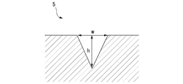
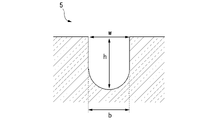
- the fine groove 5 has a rectangular cross-sectional shape.
- the interval (pitch) between adjacent fine grooves 5 is p
- the depth of the fine grooves 5 is h
- the width of the opening is w
- the width of the bottom is b
- the value of w is 0.3. ⁇ 2.0 mm is desirable.
- the value of b/w is desirably 0 to 2.0 (details will be described later, but when this value is 0, the fine groove 5 has a triangular cross section. equivalent to ).
- it is desirable that the value of h/w is 0.5 to 2.0.
- the value of p/w is desirably 0.5 to 3.0.
- the steam passing through the paragraphs in the main flow path of the turbine has its energy converted into rotational energy every time it passes through the paragraphs from the upstream side to the downstream side, and the temperature (and pressure) drops. Therefore, in the stator blade cascade 9 on the most downstream side, part of the steam is liquefied and exists in the airflow as fine droplets. Adheres to surfaces. This droplet grows and becomes a liquid film. Furthermore, as the droplets continue to increase, the thickness of the liquid film increases as it flows downstream. It scatters as coarse droplets from the trailing edge of the blade. The scattered droplets flow downstream while being gradually accelerated by the steam flow. When the coarse droplets collide with the moving blade 8 on the downstream side, erosion may occur on the surface of the moving blade 8 . Moreover, the collision of droplets may hinder the rotation of the moving blades 8 (rotor 2), resulting in braking loss.
- a plurality of fine grooves 5 are formed on the surface of the stationary blade main body 22 as described above.
- the droplets trapped in the fine grooves 5 flow downstream along with the steam flow.
- the droplets flow along the first microgrooves 51 towards the slits 13 .
- the droplet is collected by the negative pressure of the slit 13 .
- droplets flow radially outward along the second fine grooves 52 and are guided to the inner peripheral surface of the outer ring 21 . In other words, the droplets do not reach the rotor blades 8 on the downstream side.
- droplets flow radially inward along the third fine grooves 53 . As a result, the droplets do not reach the tip portion of the moving blade 8 where the peripheral speed is high.
- the distance between the first fine grooves 51 becomes narrower from the upstream side toward the recovery portion 14 (slits 13).
- the liquid film and droplets can be guided toward the recovery section 14 from a wider range on the upstream side.
- the size of the collection unit 14 itself can be reduced accordingly. As a result, it is possible to reduce the possibility that the main flow of steam will be affected, compared to the case where the recovery section 14 is large.
- the liquid film generated radially outside the central region 41 can be guided further radially outward (for example, the inner peripheral surface of the outer ring 21) by the second fine grooves 52. This can further reduce the possibility of droplets scattering downstream of the stator vane main body 22 .
- the liquid film generated inside the central region 41 in the radial direction can be guided further inward in the radial direction by the third fine grooves 53 . This can further reduce the possibility of droplets scattering downstream of the stator vane main body 22 .
- the first fine grooves 51b are curved radially outward from the front edge 22a side toward the slit 13 side.
- the turning angle which is the angle formed by the extending direction of the first fine grooves 51b with respect to the flow direction F of the steam, gradually decreases toward the slit 13 . That is, the portion of the first fine groove 51b on the slit 13 side has a larger radius of curvature than the portion on the front edge 22a side. In other words, the rate of increase in the turning angle is gradually reduced from the front edge 22a side toward the slit 13 side. It is also possible to make the portion on the slit 13 side a clothoid curve.
- the direction in which the first fine grooves 51b extend changes along the flow direction of the steam toward the slit 13 .
- the flow velocity of the liquid film increases as it approaches the slit 13, making it possible to collect the liquid film more efficiently.
- a main groove 51c and a sub-groove 51d are formed as the fine grooves 5 in the central region 41 .
- the main groove 51c extends from the front edge 22a side toward the slit 13, and the distance between adjacent main grooves 51c is narrowed.
- the minor groove 51d starts from the front edge 22a side and merges with one of the main grooves 51c at the end point.
- the shape of the fine grooves 5 can be changed variously as long as the above-described dimensional conditions are satisfied.
- FIG. 6 it is possible to make the width b of the bottom portion larger than the width w of the opening (b>w).
- FIG. 7 it is also possible to make the width b of the bottom portion smaller than the width w of the opening (b ⁇ w).
- a turbine stator vane (stator vane 10) includes a stator vane body 22 extending in a radial direction that intersects the steam flow direction, and a and a plurality of first fine grooves 51 formed on the surface of the stationary blade main body 22 and extending from the upstream side in the flow direction toward the recovery portion 14 are formed.
- a central region 41 is provided, and the interval between the first fine grooves 51 adjacent to each other is narrowed from the upstream side toward the recovery portion 14 .
- the distance between the first fine grooves 51 becomes narrower from the upstream side toward the recovery section 14 .
- the liquid film can be guided toward the recovery section 14 from a wider range on the upstream side.
- the size of the collection unit 14 itself can be reduced. This can reduce the possibility of affecting the main stream of steam.
- the turning angle which is the angle formed by the extending direction of the first fine grooves 51b with respect to the flow direction, increases toward the collecting portion 14. It may be gradually smaller.
- the direction in which the first fine grooves 51b extend changes along the flow direction of the steam toward the recovery section 14 .
- the flow velocity of the liquid film increases as it approaches the collecting section 14, and the liquid film can be collected more efficiently.
- the turning angle which is the angle formed by the extending direction of the first fine grooves 51b with respect to the flow direction, toward the collecting portion 14
- the rate of increase may gradually decrease.
- the rate of increase in the turning angle of the first fine grooves 51b gradually decreases toward the collecting portion 14.
- the flow velocity of the liquid film increases as it approaches the collecting section 14, and the liquid film can be collected more efficiently.
- the turbine stator vane (stator vane 10) according to the fourth aspect is formed radially outward of the central region 41 on the surface of the stator vane main body 22, and is radially outward from the upstream side toward the downstream side.
- the outer region 42 may further include a plurality of second microgrooves 52 extending toward the outer region 42 .
- the liquid film generated on the radially outer side of the central region 41 can be guided further radially outward (for example, the inner peripheral surface of the outer ring 21) by the second fine grooves 52. This can further reduce the possibility of droplets scattering downstream of the stator vane main body 22 .
- the turbine stator vane (stator vane 10) is formed radially inward of the central region 41 on the surface of the stator vane main body 22, and is radially inward from the upstream side toward the downstream side. It may further include an inner region 43 formed with a plurality of third microgrooves 53 extending toward.
- the liquid film generated inside the central region 41 in the radial direction can be guided further radially inward by the third fine grooves 53 . This can further reduce the possibility of droplets scattering downstream of the stator vane main body 22 .
- the steam turbine 1 includes a rotating shaft 6 extending along the axis O, and a plurality of turbine rotor blades extending radially outward from the outer peripheral surface of the rotating shaft 6 and arranged in the circumferential direction. (moving blades 8), a casing 3 covering the rotating shaft 6 and the plurality of turbine moving blades from the outside, and a plurality of rotating blades extending radially inward from the inner peripheral surface of the casing 3 and arranged in the circumferential direction. and a turbine stator vane (stator vane 10) according to any one of the aspects described above.
Landscapes
- Engineering & Computer Science (AREA)
- Mechanical Engineering (AREA)
- General Engineering & Computer Science (AREA)
- Architecture (AREA)
- Turbine Rotor Nozzle Sealing (AREA)
Abstract
Description
本願は、2021年6月28日に日本に出願された特願2021-106944号について優先権を主張し、その内容をここに援用する。
以下、本開示の実施形態に係る蒸気タービン1、及び静翼10(タービン静翼)について、図1と図2を参照して説明する。図1に示すように、蒸気タービン1は、ロータ2と、ケーシング3と、を備えている。
図2に示すように、動翼8は、プラットフォーム81と、動翼本体82と、シュラウド83と、を有している。プラットフォーム81は、回転軸6の外周面(回転軸外周面6A)に設置される。プラットフォーム81の外周側には、動翼本体82が設けられている。動翼本体82は、径方向に延びるとともに、径方向から見て翼型の断面形状を有している。動翼本体82は、一例として径方向内側から外側に向かうに従って軸線O方向の寸法が次第に減少するように形成されている。動翼本体82の径方向外側の端部にはシュラウド83が設けられている。シュラウド83は、軸線O方向を長手方向とする略矩形の断面形状を有している。シュラウド83の外周面は、ケーシング本体3Hの内周面(ケーシング内周面3A)に対して径方向に間隔をあけて対向している。
静翼10は、外輪21と、静翼本体22(翼本体)と、内輪23とを有している。また、静翼本体22は、中央領域41と、外側領域42と、内側領域43と、スリット13(回収部14)と、を有している。外輪21は、軸線Oを中心とする円環状をなしている。外輪21は、ケーシング本体3Hに対して支持部材(図示せず)を介して支持されている。静翼本体22は、外輪21と内輪23の間に固設されている。静翼本体22は、外輪内周面21Aから径方向内側に向かって延びるとともに、径方向から見て翼型の断面形状を有している。つまり、静翼本体22は、蒸気の流れ方向に交差する方向に延びている。静翼本体22は、一例として径方向外側から内側に向かうに従って、軸線O方向の寸法が次第に減少している。静翼本体22の径方向内側の端部には、内輪23が設けられている。内輪23は、軸線O方向を長手方向とする略矩形の断面形状を有している。内輪23の内周面は、回転軸外周面6Aに対して径方向に間隔をあけて対向している。
続いて、本実施形態に係る蒸気タービン1の動作、及び静翼10における液滴の挙動について説明する。蒸気タービン1を運転するに当たっては、まず蒸気流路11を通じてケーシング本体3Hの内部に高温高圧の蒸気を導入する。蒸気は、ケーシング本体3Hの内部を下流側に向かって流通する中途で、上述の静翼翼列9、及び動翼翼列7を交互に通過する。静翼翼列9は、蒸気の流れを整流して、下流側に隣接する動翼翼列7に流入する。動翼翼列7に蒸気が作用することによって、当該動翼翼列7を通じて回転軸6にトルクが与えられる。このトルクによって、ロータ2が軸線O回りに回転する。ロータ2の回転エネルギーは、軸端から取り出されて、発電機(不図示)の駆動等に用いられる。
以上、本開示の実施形態について説明した。なお、本開示の要旨を逸脱しない限りにおいて、上記の構成に種々の変更や改修を施すことが可能である。
各実施形態に記載の装置Xは、例えば以下のように把握される。
2 ロータ
3 ケーシング
3A ケーシング内周面
3H ケーシング本体
5 微細溝
6 回転軸
6A 回転軸外周面
7 動翼翼列
8 動翼(タービン動翼)
9 静翼翼列
10 静翼(タービン静翼)
11 蒸気流路
12 排気室
13 スリット
14 回収部
21 外輪
21A 外輪内周面
22 静翼本体(翼本体)
22a 前縁
22b 後縁
23 内輪
41 中央領域
42 外側領域
43 内側領域
51,51b 第一微細溝
51c 主溝
51d 副溝
52 第二微細溝
53 第三微細溝
81 プラットフォーム
82 動翼本体
83 シュラウド
O 軸線
Claims (6)
- 蒸気の流れ方向に交差する径方向に延びる静翼本体と、
該静翼本体の表面に形成され、該表面に沿って流れる液膜を回収する回収部と、
前記静翼本体の表面に形成され、前記流れ方向の上流側から前記回収部に向かって延びる複数の第一微細溝が形成された中央領域と、
を備え、
上流側から前記回収部に向かうに従って、互いに隣り合う前記第一微細溝同士の間の間隔が狭くなっているタービン静翼。 - 前記回収部に向かうに従って、前記流れ方向に対して前記第一微細溝の延びる方向がなす角度である転向角が次第に小さくなっている請求項1に記載のタービン静翼。
- 前記回収部に向かうに従って、前記流れ方向に対して前記第一微細溝の延びる方向がなす角度である転向角の増加率が次第に小さくなっている請求項1に記載のタービン静翼。
- 前記静翼本体の表面における前記中央領域の径方向外側に形成され、上流側から下流側に向かうに従って径方向外側に向かって延びる複数の第二微細溝が形成された外側領域をさらに備える請求項1から3のいずれか一項に記載のタービン静翼。
- 前記静翼本体の表面における前記中央領域の径方向内側に形成され、上流側から下流側に向かうに従って径方向内側に向かって延びる複数の第三微細溝が形成された内側領域をさらに備える請求項1から4のいずれか一項に記載のタービン静翼。
- 軸線に沿って延びる回転軸と、
該回転軸の外周面から径方向外側に延びるとともに周方向に配列された複数のタービン動翼と、
前記回転軸、及び前記複数のタービン動翼を外側から覆うケーシングと、
該ケーシングの内周面から径方向内側に向かって延びるとともに周方向に複数配列された請求項1から5のいずれか一項に記載のタービン静翼と、
を備える蒸気タービン。
Priority Applications (5)
| Application Number | Priority Date | Filing Date | Title |
|---|---|---|---|
| JP2023531452A JPWO2023276385A1 (ja) | 2021-06-28 | 2022-03-30 | |
| US18/032,054 US20230392510A1 (en) | 2021-06-28 | 2022-03-30 | Turbine stator vane and steam turbine |
| EP22832546.0A EP4212705A4 (en) | 2021-06-28 | 2022-03-30 | TURBINE AND STEAM TURBINE STATOR BLADE |
| CN202280006880.6A CN116368288A (zh) | 2021-06-28 | 2022-03-30 | 涡轮静叶片及蒸汽涡轮 |
| KR1020237016526A KR20230088458A (ko) | 2021-06-28 | 2022-03-30 | 터빈 정익, 및 증기 터빈 |
Applications Claiming Priority (2)
| Application Number | Priority Date | Filing Date | Title |
|---|---|---|---|
| JP2021106944 | 2021-06-28 | ||
| JP2021-106944 | 2021-06-28 |
Publications (1)
| Publication Number | Publication Date |
|---|---|
| WO2023276385A1 true WO2023276385A1 (ja) | 2023-01-05 |
Family
ID=84692662
Family Applications (1)
| Application Number | Title | Priority Date | Filing Date |
|---|---|---|---|
| PCT/JP2022/015932 WO2023276385A1 (ja) | 2021-06-28 | 2022-03-30 | タービン静翼、及び蒸気タービン |
Country Status (6)
| Country | Link |
|---|---|
| US (1) | US20230392510A1 (ja) |
| EP (1) | EP4212705A4 (ja) |
| JP (1) | JPWO2023276385A1 (ja) |
| KR (1) | KR20230088458A (ja) |
| CN (1) | CN116368288A (ja) |
| WO (1) | WO2023276385A1 (ja) |
Citations (6)
| Publication number | Priority date | Publication date | Assignee | Title |
|---|---|---|---|---|
| JPS63263204A (ja) * | 1987-04-21 | 1988-10-31 | Toshiba Corp | タ−ビンの羽根侵食防止装置 |
| JPS6480705A (en) * | 1987-09-24 | 1989-03-27 | Hitachi Ltd | Stationary blade construction for steam turbine |
| EP2985426A1 (en) * | 2014-08-12 | 2016-02-17 | Siemens Aktiengesellschaft | Blade device for a turbine and corresponding manufacturing method |
| JP2016166569A (ja) | 2015-03-09 | 2016-09-15 | 株式会社東芝 | 蒸気タービン |
| JP2017106451A (ja) * | 2015-12-11 | 2017-06-15 | ゼネラル・エレクトリック・カンパニイ | 蒸気タービン、蒸気タービンノズル、並びに蒸気タービンで水分を管理する方法 |
| JP2021106944A (ja) | 2018-09-24 | 2021-07-29 | 株式会社藤商事 | 遊技機 |
Family Cites Families (5)
| Publication number | Priority date | Publication date | Assignee | Title |
|---|---|---|---|---|
| DE19546008A1 (de) * | 1995-12-09 | 1997-06-12 | Abb Patent Gmbh | Turbinenschaufel, die für den Einsatz im Naßdampfbereich von Vorend- und Endstufen von Turbinen vorgesehen ist |
| JP4886271B2 (ja) * | 2005-10-31 | 2012-02-29 | 株式会社東芝 | 蒸気タービンおよびその親水性コーティング材料 |
| JP6393178B2 (ja) * | 2014-12-15 | 2018-09-19 | 三菱日立パワーシステムズ株式会社 | 蒸気タービン静翼 |
| JP7179651B2 (ja) * | 2019-02-27 | 2022-11-29 | 三菱重工業株式会社 | タービン静翼、及び蒸気タービン |
| US11773753B2 (en) * | 2019-12-11 | 2023-10-03 | Mitsubishi Heavy Industries, Ltd. | Turbine stator vane, turbine stator vane assembly, and steam turbine |
-
2022
- 2022-03-30 KR KR1020237016526A patent/KR20230088458A/ko unknown
- 2022-03-30 JP JP2023531452A patent/JPWO2023276385A1/ja active Pending
- 2022-03-30 EP EP22832546.0A patent/EP4212705A4/en active Pending
- 2022-03-30 US US18/032,054 patent/US20230392510A1/en active Pending
- 2022-03-30 CN CN202280006880.6A patent/CN116368288A/zh active Pending
- 2022-03-30 WO PCT/JP2022/015932 patent/WO2023276385A1/ja unknown
Patent Citations (6)
| Publication number | Priority date | Publication date | Assignee | Title |
|---|---|---|---|---|
| JPS63263204A (ja) * | 1987-04-21 | 1988-10-31 | Toshiba Corp | タ−ビンの羽根侵食防止装置 |
| JPS6480705A (en) * | 1987-09-24 | 1989-03-27 | Hitachi Ltd | Stationary blade construction for steam turbine |
| EP2985426A1 (en) * | 2014-08-12 | 2016-02-17 | Siemens Aktiengesellschaft | Blade device for a turbine and corresponding manufacturing method |
| JP2016166569A (ja) | 2015-03-09 | 2016-09-15 | 株式会社東芝 | 蒸気タービン |
| JP2017106451A (ja) * | 2015-12-11 | 2017-06-15 | ゼネラル・エレクトリック・カンパニイ | 蒸気タービン、蒸気タービンノズル、並びに蒸気タービンで水分を管理する方法 |
| JP2021106944A (ja) | 2018-09-24 | 2021-07-29 | 株式会社藤商事 | 遊技機 |
Non-Patent Citations (1)
| Title |
|---|
| See also references of EP4212705A4 |
Also Published As
| Publication number | Publication date |
|---|---|
| CN116368288A (zh) | 2023-06-30 |
| KR20230088458A (ko) | 2023-06-19 |
| EP4212705A4 (en) | 2023-11-29 |
| US20230392510A1 (en) | 2023-12-07 |
| JPWO2023276385A1 (ja) | 2023-01-05 |
| EP4212705A1 (en) | 2023-07-19 |
Similar Documents
| Publication | Publication Date | Title |
|---|---|---|
| JP7292421B2 (ja) | タービン静翼、タービン静翼組立体、及び蒸気タービン | |
| JP5592326B2 (ja) | 蒸気タービンの静翼、及びそれを用いた蒸気タービン | |
| JP5651459B2 (ja) | タービンエンジンにおける圧縮機の動作に関するシステム及び装置 | |
| JPH0319882B2 (ja) | ||
| EP2617951A2 (en) | Tip cover of a steam turbine for the drainage of water droplets | |
| JP3786458B2 (ja) | 軸流タービン翼 | |
| JP2016166569A (ja) | 蒸気タービン | |
| JP7179652B2 (ja) | タービン静翼、及び蒸気タービン | |
| JP6518526B2 (ja) | 軸流タービン | |
| WO2023276385A1 (ja) | タービン静翼、及び蒸気タービン | |
| JP2009036112A (ja) | 回転機械の翼 | |
| JP4184565B2 (ja) | 蒸気タービンノズルおよびその蒸気タービンノズルを用いた蒸気タービン | |
| JP6125351B2 (ja) | 蒸気タービン | |
| JP5651532B2 (ja) | 蒸気タービン | |
| JP2005299680A (ja) | 軸流タービン翼 | |
| JP2020020465A (ja) | シール装置およびターボ機械 | |
| JP7368260B2 (ja) | タービン | |
| WO2022034756A1 (ja) | タービン静翼、及び蒸気タービン | |
| JP5916586B2 (ja) | 蒸気タービン | |
| JP5470285B2 (ja) | 軸流タービン | |
| JP2011074804A (ja) | 蒸気タービンのノズル | |
| JPH11173104A (ja) | タービン動翼 | |
| JP2007138864A (ja) | 蒸気タービン段落および蒸気タービン | |
| CN111287801A (zh) | 蒸汽轮机叶片以及蒸汽轮机 | |
| JPS6332963B2 (ja) |
Legal Events
| Date | Code | Title | Description |
|---|---|---|---|
| 121 | Ep: the epo has been informed by wipo that ep was designated in this application |
Ref document number: 22832546 Country of ref document: EP Kind code of ref document: A1 |
|
| ENP | Entry into the national phase |
Ref document number: 2023531452 Country of ref document: JP Kind code of ref document: A |
|
| ENP | Entry into the national phase |
Ref document number: 2022832546 Country of ref document: EP Effective date: 20230413 |
|
| ENP | Entry into the national phase |
Ref document number: 20237016526 Country of ref document: KR Kind code of ref document: A |
|
| NENP | Non-entry into the national phase |
Ref country code: DE |