WO2023276345A1 - 作業機 - Google Patents
作業機 Download PDFInfo
- Publication number
- WO2023276345A1 WO2023276345A1 PCT/JP2022/014329 JP2022014329W WO2023276345A1 WO 2023276345 A1 WO2023276345 A1 WO 2023276345A1 JP 2022014329 W JP2022014329 W JP 2022014329W WO 2023276345 A1 WO2023276345 A1 WO 2023276345A1
- Authority
- WO
- WIPO (PCT)
- Prior art keywords
- boom
- arm
- straight line
- support shaft
- cylinder
- Prior art date
- Legal status (The legal status is an assumption and is not a legal conclusion. Google has not performed a legal analysis and makes no representation as to the accuracy of the status listed.)
- Ceased
Links
Images





Classifications
-
- E—FIXED CONSTRUCTIONS
- E02—HYDRAULIC ENGINEERING; FOUNDATIONS; SOIL SHIFTING
- E02F—DREDGING; SOIL-SHIFTING
- E02F3/00—Dredgers; Soil-shifting machines
- E02F3/04—Dredgers; Soil-shifting machines mechanically-driven
- E02F3/28—Dredgers; Soil-shifting machines mechanically-driven with digging tools mounted on a dipper- or bucket-arm, i.e. there is either one arm or a pair of arms, e.g. dippers, buckets
- E02F3/36—Component parts
- E02F3/38—Cantilever beams, i.e. booms;, e.g. manufacturing processes, forms, geometry or materials used for booms; Dipper-arms, e.g. manufacturing processes, forms, geometry or materials used for dipper-arms; Bucket-arms
- E02F3/382—Connections to the frame; Supports for booms or arms
- E02F3/384—Connections to the frame; Supports for booms or arms the boom being pivotable relative to the frame about a vertical axis
-
- E—FIXED CONSTRUCTIONS
- E02—HYDRAULIC ENGINEERING; FOUNDATIONS; SOIL SHIFTING
- E02F—DREDGING; SOIL-SHIFTING
- E02F3/00—Dredgers; Soil-shifting machines
- E02F3/04—Dredgers; Soil-shifting machines mechanically-driven
- E02F3/28—Dredgers; Soil-shifting machines mechanically-driven with digging tools mounted on a dipper- or bucket-arm, i.e. there is either one arm or a pair of arms, e.g. dippers, buckets
- E02F3/30—Dredgers; Soil-shifting machines mechanically-driven with digging tools mounted on a dipper- or bucket-arm, i.e. there is either one arm or a pair of arms, e.g. dippers, buckets with a dipper-arm pivoted on a cantilever beam, i.e. boom
- E02F3/32—Dredgers; Soil-shifting machines mechanically-driven with digging tools mounted on a dipper- or bucket-arm, i.e. there is either one arm or a pair of arms, e.g. dippers, buckets with a dipper-arm pivoted on a cantilever beam, i.e. boom working downwardly and towards the machine, e.g. with backhoes
-
- E—FIXED CONSTRUCTIONS
- E02—HYDRAULIC ENGINEERING; FOUNDATIONS; SOIL SHIFTING
- E02F—DREDGING; SOIL-SHIFTING
- E02F3/00—Dredgers; Soil-shifting machines
- E02F3/04—Dredgers; Soil-shifting machines mechanically-driven
- E02F3/28—Dredgers; Soil-shifting machines mechanically-driven with digging tools mounted on a dipper- or bucket-arm, i.e. there is either one arm or a pair of arms, e.g. dippers, buckets
- E02F3/30—Dredgers; Soil-shifting machines mechanically-driven with digging tools mounted on a dipper- or bucket-arm, i.e. there is either one arm or a pair of arms, e.g. dippers, buckets with a dipper-arm pivoted on a cantilever beam, i.e. boom
- E02F3/32—Dredgers; Soil-shifting machines mechanically-driven with digging tools mounted on a dipper- or bucket-arm, i.e. there is either one arm or a pair of arms, e.g. dippers, buckets with a dipper-arm pivoted on a cantilever beam, i.e. boom working downwardly and towards the machine, e.g. with backhoes
- E02F3/325—Backhoes of the miniature type
-
- E—FIXED CONSTRUCTIONS
- E02—HYDRAULIC ENGINEERING; FOUNDATIONS; SOIL SHIFTING
- E02F—DREDGING; SOIL-SHIFTING
- E02F3/00—Dredgers; Soil-shifting machines
- E02F3/04—Dredgers; Soil-shifting machines mechanically-driven
- E02F3/28—Dredgers; Soil-shifting machines mechanically-driven with digging tools mounted on a dipper- or bucket-arm, i.e. there is either one arm or a pair of arms, e.g. dippers, buckets
- E02F3/36—Component parts
- E02F3/38—Cantilever beams, i.e. booms;, e.g. manufacturing processes, forms, geometry or materials used for booms; Dipper-arms, e.g. manufacturing processes, forms, geometry or materials used for dipper-arms; Bucket-arms
-
- E—FIXED CONSTRUCTIONS
- E02—HYDRAULIC ENGINEERING; FOUNDATIONS; SOIL SHIFTING
- E02F—DREDGING; SOIL-SHIFTING
- E02F3/00—Dredgers; Soil-shifting machines
- E02F3/04—Dredgers; Soil-shifting machines mechanically-driven
- E02F3/28—Dredgers; Soil-shifting machines mechanically-driven with digging tools mounted on a dipper- or bucket-arm, i.e. there is either one arm or a pair of arms, e.g. dippers, buckets
- E02F3/36—Component parts
- E02F3/42—Drives for dippers, buckets, dipper-arms or bucket-arms
- E02F3/425—Drive systems for dipper-arms, backhoes or the like
-
- E—FIXED CONSTRUCTIONS
- E02—HYDRAULIC ENGINEERING; FOUNDATIONS; SOIL SHIFTING
- E02F—DREDGING; SOIL-SHIFTING
- E02F9/00—Component parts of dredgers or soil-shifting machines, not restricted to one of the kinds covered by groups E02F3/00 - E02F7/00
- E02F9/20—Drives; Control devices
- E02F9/22—Hydraulic or pneumatic drives
- E02F9/2264—Arrangements or adaptations of elements for hydraulic drives
- E02F9/2275—Hoses and supports therefor and protection therefor
-
- E—FIXED CONSTRUCTIONS
- E02—HYDRAULIC ENGINEERING; FOUNDATIONS; SOIL SHIFTING
- E02F—DREDGING; SOIL-SHIFTING
- E02F3/00—Dredgers; Soil-shifting machines
- E02F3/04—Dredgers; Soil-shifting machines mechanically-driven
- E02F3/96—Dredgers; Soil-shifting machines mechanically-driven with arrangements for alternate or simultaneous use of different digging elements
- E02F3/963—Arrangements on backhoes for alternate use of different tools
- E02F3/964—Arrangements on backhoes for alternate use of different tools of several tools mounted on one machine
-
- E—FIXED CONSTRUCTIONS
- E02—HYDRAULIC ENGINEERING; FOUNDATIONS; SOIL SHIFTING
- E02F—DREDGING; SOIL-SHIFTING
- E02F9/00—Component parts of dredgers or soil-shifting machines, not restricted to one of the kinds covered by groups E02F3/00 - E02F7/00
- E02F9/16—Cabins, platforms, or the like, for drivers
-
- E—FIXED CONSTRUCTIONS
- E02—HYDRAULIC ENGINEERING; FOUNDATIONS; SOIL SHIFTING
- E02F—DREDGING; SOIL-SHIFTING
- E02F9/00—Component parts of dredgers or soil-shifting machines, not restricted to one of the kinds covered by groups E02F3/00 - E02F7/00
- E02F9/20—Drives; Control devices
- E02F9/22—Hydraulic or pneumatic drives
- E02F9/2203—Arrangements for controlling the attitude of actuators, e.g. speed, floating function
-
- E—FIXED CONSTRUCTIONS
- E02—HYDRAULIC ENGINEERING; FOUNDATIONS; SOIL SHIFTING
- E02F—DREDGING; SOIL-SHIFTING
- E02F9/00—Component parts of dredgers or soil-shifting machines, not restricted to one of the kinds covered by groups E02F3/00 - E02F7/00
- E02F9/20—Drives; Control devices
- E02F9/22—Hydraulic or pneumatic drives
- E02F9/2278—Hydraulic circuits
Definitions
- the present invention relates to working machines.
- Patent Document 1 a working machine disclosed in Patent Document 1 is known.
- the work machine disclosed in Patent Document 1 has a boom that is supported by a boom support provided in front of the machine body so as to be able to swing up and down.
- the boom is bent at an intermediate portion in the longitudinal direction of the boom, which is a portion between the boom base pivoted on the boom support, the boom tip pivoted on the arm, and the boom base and boom tip.
- the boom body includes a first section between the intermediate section and the boom base and a second section between the intermediate section and the tip section.
- the boom extends in an inclined direction in which the first part extends upward from the boom base and the second part shifts forward as it goes upward from the middle part at the highest position where the boom is swung upwards. be done.
- a work machine includes a machine body, a boom support provided in front of the machine body, a boom base pivotally supported by the boom support via a boom support shaft, and an arm support shaft. and a boom main body bent at an intermediate portion in the longitudinal direction of the boom between the boom base and the boom tip, wherein the a boom that can swing up and down around a boom support shaft; a boom cylinder that is pivotally supported by a support via a second cylinder support shaft and expands and contracts to swing the boom, wherein the boom is in the highest position where the boom is swung upwards.
- a first straight line perpendicular to the arm support shaft and the first cylinder support shaft and extending downward from the first cylinder support shaft extends in a tilt direction that shifts forward as it goes upward from the part. It is configured to pass through the front of the fuselage.
- the work machine includes a driver's seat mounted on the machine body, and the boom is an extension of the back surface of the second section at the highest position and extends downward from the back surface of the second section.
- a first extension line is configured to pass in front of the driver's seat.
- the work machine includes a driver's seat mounted on the machine body, and the boom extends downward from the front of the second section at the highest position and is an extension of the front of the second section.
- a second extension line is configured to pass in front of the driver's seat.
- a straight line orthogonal to the arm support shaft and the boom support shaft is defined as a second straight line
- a straight line orthogonal to the second straight line and the first cylinder support shaft is defined as a third straight line
- the straight line orthogonal to the first cylinder support shaft is defined as a third straight line.
- the intersection of two straight lines and the third straight line is defined as a first intersection
- the intersection of the third straight line and the front surface of the boom body is defined as a second intersection
- the intersection of the second straight line and the rear surface of the boom body is defined as a second intersection.
- a first distance between the first intersection point and the second intersection point is smaller than a second distance between the second intersection point and the third intersection point.
- a vertical line orthogonal to the arm support shaft is defined as a fourth straight line
- a straight line orthogonal to the fourth straight line and the first cylinder support shaft is defined as a fifth straight line
- a vertical line orthogonal to the boom support shaft is defined as a sixth straight line and a vertical line orthogonal to the second cylinder support shaft is defined as a seventh straight line at the highest position
- the fourth straight line and the fourth straight line A seventh distance between the 7 straight lines is less than an 8th distance between the sixth straight line and the seventh straight line. Also, the sixth distance is greater than a ninth vertical distance between the fifth straight line and the upper edge of the side surface of the boom base.
- the boom base has a pivot portion that is pivotally supported via the boom support shaft, and a connection portion that is connected to the first portion of the boom main body, and the boom is connected to the topmost portion.
- the pivot portion In a state of being swung to the raised position, the pivot portion extends in an inclined direction that shifts rearward as it goes upward from the boom support shaft side, and the connection portion extends upward from the pivot portion. It is bent between the pivot portion and the connection portion.
- a first bending angle between the front surface of the first portion and the front surface of the second portion is larger than a second bending angle between the front surface of the pivotal support portion and the front surface of the connecting portion.
- the work implement is pivotally supported by the arm via a work implement spindle, and swings around the work implement support shaft, whereby the work implement crowd position where the tip portion is closest to the arm, and A work tool whose tip is swingable between a work tool dumping position at which it is the farthest from the arm, and an arm cylinder that swings the arm in an arm crowding direction toward the boom and an arm dumping direction away from the boom. and an arm-crowding restricting portion that restricts the stroke of the arm cylinder in the arm-crowding direction so that the swinging trajectory of the tip portion of the work implement and the boom cylinder are separated by a predetermined distance or more.
- the work implement is pivotally supported by the arm via a work implement spindle, and swings around the work implement support shaft, whereby the work implement crowd position where the tip portion is closest to the arm, and a work tool whose tip is swingable between a work tool dump position where the tip is the farthest from the arm, a work tool cloud direction in which the tip of the work tool approaches the work tool cloud position, and
- the work implement cylinder which causes the tip portion to swing in the work implement dumping direction approaching the work implement dumping position, and the swing track of the tip portion of the work implement and the boom cylinder, are spaced apart by a predetermined distance or more. and a work implement cloud limiter that limits the stroke of the work implement cylinder in the work implement cloud direction.
- the first portion of the boom body extends upward from the boom base toward the intermediate portion, and the second portion of the boom body extends upward.
- a first straight line perpendicular to the arm support shaft and the first cylinder support shaft and extending downward from the first cylinder support shaft passes forward of the fuselage, the bending angle of the boom (the angle formed by the first portion and the second portion) becomes larger than before. This makes it possible to increase the height of the tip of the boom when the boom is in the highest position, and reduce the weight of the boom.
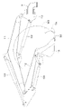
- FIG. 4 is a perspective view of a state in which a boom is pivotally supported by a swing bracket;
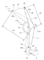
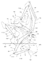
- FIG. 4 is a side view for explaining the shape of a boom;
- FIG. 4 is a side view for explaining the shape of a boom;
- FIG. 4 is a side view for explaining the shape of a boom;
- FIG. 4 is a side view for explaining the shape of a boom;
- It is a side view for demonstrating the effect of the boom of this embodiment. It is a side view when the boom is in the lowered position.
- FIG. 5 is a diagram showing a change state of the swinging position of the boom; It is a side view of the state of dustpan work. It is a perspective view which shows the wiring state of a hydraulic hose.
- FIG. 1 is a schematic side view showing the overall configuration of a working machine 1 according to this embodiment.
- a backhoe which is a turning work machine
- the working machine 1 includes a machine body (swivel base) 2 , a traveling device 3 , and a working device 4 .
- the aircraft 2 is equipped with a driver's seat 6 on which an operator (driver) sits.
- a canopy 5 is mounted on the airframe 2 .
- the canopy 5 is a driver's seat protection device that protects the driver's seat 6 .
- a cabin surrounding the driver's seat 6 may be mounted instead of the canopy 5 as the driver's seat protection device.
- the direction toward the front of the operator seated on the driver's seat 6 of the work machine 1 is forward (the front of the machine body), and the direction toward the rear of the operator (direction of arrow A2 in FIG. 1) 1 is defined as the rearward direction (backward direction of the fuselage), and the direction of the arrow K1 in FIG.
- the direction toward the left side of the operator front side in FIG. 1 will be described as the left side
- the direction toward the right side of the operator back side in FIG. 1 will be described as the right side.
- the horizontal direction which is the direction orthogonal to the longitudinal direction K1
- the body width direction The direction from the central portion in the width direction of the body 2 to the right or left portion will be described as the outer side in the width direction of the body. That is, the outer side in the body width direction is the direction away from the center of the body 2 in the width direction in the body width direction.
- the direction opposite to the outer side in the width direction of the machine body will be described as the inner side in the width direction of the machine body. That is, the inner side in the width direction of the body is the direction toward the center of the width direction of the body 2 in the width direction of the body.
- the traveling device 3 is a crawler-type traveling device that supports the body 2 so as to be able to travel, and includes a traveling frame 3A, a first traveling device 3L provided on the left side of the traveling frame 3A, and a second traveling device 3R provided on the right side of the traveling frame 3A.
- the first travel device 3L and the second travel device 3R are driven by a travel motor M1 configured by a hydraulic motor (hydraulic actuator).
- a travel motor M1 configured by a hydraulic motor (hydraulic actuator).
- the crawler-type traveling device 3 is used in this embodiment, the present invention is not limited to this, and a wheel-type traveling device or the like may be used.
- a dozer device 7 is attached to the front portion of the traveling device 3 .
- the dozer device 7 can move up and down (raise and lower) a blade (discharge plate) 7A by extending and contracting a dozer cylinder (hydraulic actuator) not shown.
- the fuselage 2 has a turning base plate 15 that turns around a turning axis X1 that extends vertically.
- the swivel base plate 15 is made of a steel plate or the like, and constitutes the bottom of the airframe 2 .
- a weight 14 is provided at the rear portion of the fuselage 2 .
- the machine body 2 (swivel base plate 15) is supported on the travel device 3 via a swivel bearing 8 so as to be swivelable around the swivel axis X1.
- the working machine 1 has a support bracket 9 and a swing bracket (boom support) 10.
- the support bracket 9 is provided so as to protrude forward from the body 2 .
- the support bracket 9 protrudes forward from the front surface 2 a of the airframe 2 .
- the swing bracket 10 is a member that supports the work device 4 and is provided in front of the machine body 2 .
- the swing bracket 10 is attached to the front portion of the support bracket 9 so as to be capable of swinging about a vertically extending swing axis 10a. Therefore, the swing bracket 10 is rotatable in the body width direction (horizontally about the swing axis 10a).
- the swing bracket 10 is swingable by extension and contraction of a swing cylinder (hydraulic actuator) (not shown).
- a motor E1 is mounted at the rear of the airframe 2.
- the prime mover E ⁇ b>1 is mounted on the turning board 15 .
- Prime mover E1 is a diesel engine.
- the prime mover E1 may be a gasoline engine, an electric motor, or a hybrid type having an engine and an electric motor.
- a driver's seat 6, a travel lever 16 arranged in front of the driver's seat 6, a control device 17L arranged on the left side of the driver's seat 6, a control device 17R arranged on the right side, etc. is mounted.
- the travel lever 16 is an operating member that operates the travel device 3 .
- the control devices 17L and 17R are devices that perform, for example, the operation of the work device 4 (swing operation of the boom 11, swing operation of the arm 12, swing operation of the bucket 13), swing operation of the machine body 2, and the like.
- a step 21 constituting a floor surface is provided on the upper surface side of the body 2 and on the front side of the driver's seat 6 .
- the working device 4 has a boom device 30, an arm device 40, and a working implement device 50.
- the boom device 30 has a boom 11 and a boom cylinder C2.
- the arm device 40 has an arm 12 and an arm cylinder C3.
- the work tool device 50 has a bucket 13 as a work tool and a bucket cylinder C4 as a work tool cylinder.
- the boom 11 includes a boom base portion 11A, a boom tip portion 11B, and a boom body portion 11C.
- the boom base 11A is pivotally supported by the swing bracket 10 via a boom support shaft 35.
- the first pivotal support portion 23 of the swing bracket 10 is swingably (rotatably) supported via a boom support shaft 35 having an axis extending in the width direction of the machine body. That is, the boom 11 swings (vertically swings) about the boom support shaft 35 in the vertical direction.
- the boom base 11A is bifurcated. Specifically, the boom base 11A has a pivotally supported portion 11Aa that is pivotally supported via the boom shaft 35, and a connection portion 11Ab that is connected to the boom main body portion 11C (first portion 11Ca).
- a pair of pivot portions 11Aa are provided in the body width direction, and are arranged so that the first pivot portion 23 is sandwiched between the left pivot portion 11Aa and the right pivot portion 11Aa in the body width direction.
- a space portion 51 is formed between the connection portion 11Ab and the swing bracket 10 and between the first pivotal support portion 23 .
- the boom base 11A is bent between the pivotal support portion 11Aa and the connection portion 11Ab (in the middle of the boom longitudinal direction, which is the longitudinal direction of the boom 11).
- the boom base 11A has a bent portion between the pivotal support portion 11Aa and the connection portion 11Ab.
- the boom tip portion 11B supports the arm 12 so as to swing freely. Specifically, the boom tip portion 11B swingably pivots the base portion of the arm 12 via an arm support shaft 43 having an axis extending in the width direction of the machine body.
- the boom tip portion 11B is bifurcated and arranged so as to sandwich the base portion of the arm 12 therebetween.
- the boom body portion 11C is a portion provided between the boom base portion 11A and the boom tip portion 11B.
- the boom main body 11C is formed by welding the side portions of four long plates along the longitudinal direction of the boom 11 (boom longitudinal direction), and has a quadrangular prism shape with a rectangular cross section perpendicular to the longitudinal direction of the boom. and is bent in the middle. Specifically, the boom main body 11C is bent at an intermediate portion 11Cc in the longitudinal direction of the boom. It has a second portion 11Cb that is a portion between the boom tip portion 11B. That is, the boom body portion 11C is bent between the first portion 11Ca and the second portion 11Cb.
- a lower bracket 33 is provided on the front side of the intermediate portion 11Cc (bending portion) of the boom body portion 11C, and an upper bracket 34 is provided on the rear side (upper side) of the intermediate portion 11Cc (bending portion) of the boom body portion 11C. It is
- the boom 11 is in a raised position 19 in which the boom 11 is swung upward with the swing bracket 10 and the boom 11 facing the front of the fuselage.
- the second portion 11Cb extends upward toward the portion 11Cc, and extends in an oblique direction that shifts forward as the second portion 11Cb goes upward from the intermediate portion 11Cc.
- the boom 11 is arranged in front of the canopy (cabin) 5 so as to overlap (superimpose) the canopy (cabin) 5 in a front view, and the boom 11 is raised.
- the boom 11 is configured to stop upward swinging at a position where the boom 11 does not interfere with the canopy (cabin) 5 when the position 19 is set.
- the raised position 19 shown in FIGS. 1 and 2 indicates the highest position where the boom 11 is swung to the highest position.
- the boom base portion 11A extends in an inclined direction in which the pivot portion 11Aa moves rearward as it goes upward from the boom support shaft 35 side at the raised position 19 of the boom 11, and the connection portion 11Ab extends upward from the pivot portion 11Aa. It is bent so as to extend.
- a bending angle (first bending angle) 27 of the boom body portion 11C (boom 11) is larger than a bending angle (second bending angle) 39 of the boom base portion 11A.
- the first bending angle 27 is an angle between the front surface 11Ca1 of the first portion 11Ca and the front surface 11Cb1 of the second portion 11Cb.
- the second bending angle 39 is an angle between the front surface 11Aa1 of the pivotal support portion 11Aa and the front surface 11Ab1 of the connection portion 11Ab.
- the boom 11 is not limited to the structure described above.
- the boom base portion 11A and the boom tip portion 11B are formed separately from the boom body portion C, but the boom 11 may be formed by integrally forming the boom base portion 11A, the boom tip portion 11B and the boom body portion C. .
- the boom base 11A does not have to be bent.
- the boom base portion 11A and the boom tip portion 11B do not have to be bifurcated.
- the boom base portion 11A and the boom tip portion 11B are made of cast iron, and the boom body portion 11C is formed by welding four plates into a tubular shape.
- the material of the portion 11B and the boom body portion 11C is not limited to this.
- the boom cylinder C2 is a telescopic hydraulic cylinder (hydraulic actuator) that swings (rotates) the boom 11.
- the boom cylinder C2 is arranged on the front side of the boom 11 (on the front side of the boom 11).
- One end of the boom cylinder C2 is pivotally supported on the front side of the boom main body portion 11C via a cylinder support shaft (first cylinder support shaft) 37 having an axis in the width direction of the machine body, and the other end is attached to the swing bracket 10.
- the boom 11 is swung by being pivotally supported via a cylinder support shaft (second cylinder support shaft) 36 having an axis in the width direction and being expanded and contracted.
- the boom cylinder C2 includes a cylindrical cylinder portion 32A and a rod 32B having one end slidably inserted into the cylinder portion 32A.
- the boom cylinder C2 is arranged on the side facing the arm 12 of the boom 11 when the arm 12 swings in the arm cloud direction D1. That is, the boom cylinder C ⁇ b>2 is arranged on the lower front side (front side) of the boom 11 .
- the tip of the boom cylinder C ⁇ b>2 (the projecting end of the rod 32 ⁇ /b>B) is swingably supported by the lower bracket 33 via the first cylinder support shaft 37 .
- a base end portion (bottom side of the cylinder portion 32A) of the boom cylinder C2 is swingably supported by the second pivotal support portion 24 of the swing bracket 10 via the second cylinder support shaft 36 . Therefore, the boom device 30 (boom 11) is rotatable around the boom support shaft 35 of the first pivot portion 23, and the boom device 30 (boom 11) can swing upward or downward.
- a guard member (cylinder guard) that prevents other objects from contacting the rod 32B and/or the cylinder portion 32A may be provided on the arm 12 side (lower side) surface of the boom cylinder C2.
- the arm 12 is elongated along its longitudinal direction.
- a base portion of the arm 12 is swingably supported by a boom tip portion 11B of the boom 11 via an arm support shaft 43 .
- An upper bracket 44 is provided on the upper surface side of the base of the arm 12 .
- the arm cylinder C3 is an extendable hydraulic cylinder (hydraulic actuator) that swings the arm 12.
- a base end of the arm cylinder C3 is swingably supported by an upper bracket 34 of the boom 11 via a cylinder support shaft (third cylinder support shaft) 38 having an axis in the machine width direction.
- the part is swingably supported by an upper bracket 44 via a cylinder support shaft (fourth cylinder support shaft) 46 having an axis in the machine width direction. Therefore, the arm device 40 (arm 12) is rotatable around the arm support shaft 43 of the boom 11, and the arm device 40 (arm 12) is swingable upward or downward (forward or backward). is. That is, as shown in FIG. 2 , the arm 12 is pivotally supported on the boom 11 so as to be swingable in an arm cloud direction D1 toward the boom 11 and an arm dump direction D2 away from the boom 11 .
- the bucket 13 is swingably supported by the tip of the arm 12 via a pivot (bucket support shaft) 57 having an axis in the machine width direction.
- a link mechanism 53 is provided between the bucket 13 and the tip of the arm 12 .
- the bucket 13 has a bucket body 13a that scoops up earth and sand, and an attachment bracket 13c that is attached to the arm 12 and the link mechanism 53 .
- the bucket main body 13 a has a bottom surface 13 b and a tip portion (claw portion) 58 .
- the bucket cylinder C4 is configured with an extendable hydraulic cylinder (hydraulic actuator) that swings the bucket 13 .
- a base end of the bucket cylinder C4 is swingably supported by an upper bracket 44 of the arm 12 via a cylinder support shaft (fifth cylinder support shaft) 48 having an axial center extending in the machine width direction.
- a tip portion of the bucket cylinder C4 is supported by a cylinder support shaft (sixth cylinder support shaft) 56 of the link mechanism 53 so as to be swingable about an axis extending in the machine width direction. Therefore, the work tool device 50 (bucket 13) is provided on the tip end side of the arm 12 so as to be able to carry out a crowd operation (squeeze operation) and a dump operation.
- the crowding operation is an operation of swinging the tip portion 58 of the bucket 13 in a bucket crowding direction (work implement crowding direction) D3, which is a direction to approach the boom 11 (arm 12). This is the operation for scooping.
- the dumping operation is an operation of swinging the tip portion 58 of the bucket 13 in a bucket dumping direction (work tool dumping direction) D4, which is a direction away from the boom 11 (arm 12). This is the operation for dropping (discharging).
- the bucket 13 is positioned at the position where the bucket cylinder C4 is most extended (most stroke in the bucket cloud direction D3) and where the tip portion 58 is closest to the arm 12 (the bucket cloud position (working tool Between the cloud position) Y1 and a bucket dump position (work implement dump position) Y2 where the bucket cylinder C4 is most contracted (the most stroke in the bucket dump direction D4) and the tip portion 58 is the farthest from the arm 12.
- M3 indicates the swing trajectory of the tip portion 58 when the bucket 13 moves between the bucket cloud position Y1 and the bucket dump position Y2.
- the work machine 1 can be equipped with other work implements (hydraulic attachments) that can be driven by hydraulic actuators.
- Other working tools include hydraulic breakers, hydraulic crushers, angle blooms, earth augers, pallet forks, sweepers, mowers, snow blowers, and the like.
- the boom 11 is perpendicular to (the axis 43 a of) the arm support shaft 43 and (the axis 37 a of) the first cylinder support shaft 37 and extends from the first cylinder support shaft 37 .
- a straight line (first straight line) 26 a extending downward is configured to pass through the front of the fuselage 2 .
- the first straight line 26 a intersects the support bracket 9 behind the swing bracket 10 .
- a downwardly extending straight line (conventional first straight line) is configured to intersect the fuselage (swivel base) (pass near the center of the fuselage in the longitudinal direction).
- the boom 11 is configured so that the first straight line 26a passes ahead of the airframe 2 . That is, the inclination angle of the first straight line 26a with respect to the horizontal line in the present embodiment is larger than the inclination angle of the conventional first straight line with respect to the horizontal line.
- the inclination angle of the first straight line 26a with respect to the horizontal line increases as the bending angle 27 of the boom 11 increases. Therefore, since the first straight line 26a is configured to pass forward of the fuselage 2, the boom 11 of the present embodiment has a bending angle 27 that is larger (shallower) than the bending angle of the conventional boom. ).
- the tip position of the boom 11 can be raised (the bucket height, which is the height position of the bucket 13, can be raised). Also, the weight of the boom 11 can be reduced (lightening of the boom 11).
- the solid line indicates the boom of this embodiment, and the two-dot chain line indicates the case where the bending angle 27 of the boom 11 is smaller than that of this embodiment (for example, (conventional) boom 11 is shown.
- Reference numeral 22 denotes an arc line centered on the axis 35a of the boom support shaft 35 and passing through the axis 43a of the arm support shaft 43 (the axis 35a of the boom support shaft 35 and the axis 43a of the arm support shaft 43). ) shows an arc line whose radius is the line connecting the Assuming that the straight line orthogonal to the arm support shaft 43 and the boom support shaft 35 has the same dimensions in the conventional art and the present embodiment, as shown in FIG.
- the position is higher in this embodiment than in the conventional art by H1, and the distance H2 between the arm support shaft 43 and the intermediate portion 11Cc of the boom body portion 11C is smaller in the present embodiment than in the conventional art. That is, in the present embodiment, by increasing the bending angle 27 of the boom, the tip position of the boom 11 can be raised and the weight of the boom 11 can be reduced.
- the bending angle 27 of the boom 11 of this embodiment is set to 140° to 170°, for example.
- the bending angle 27 is set between 145° and 165°. More preferably, the bending angle 27 is set between 150° and 160°.
- the boom 11 is an extension of the rear surface 11Cb2 of the second section 11Cb when viewed from the side in the raised position 19.
- a first extension line 28 a extending downward from the rear surface 11 Cb 2 of the driver's seat 6 passes in front of the driver's seat 6 .
- the extension line (conventional first extension line) extending downward from the rear surface of the second part when viewed from the side in the highest position is the rear part of the driver's seat (the backrest). part).
- the boom 11 is configured so that the first extension line 28 a passes in front of the driver's seat 6 . That is, the inclination angle of the first extension line 28a with respect to the horizontal line is greater than the inclination angle of the conventional first extension line with respect to the horizontal line. The inclination angle of the first extension line 28a with respect to the horizontal line increases as the bending angle 27 of the boom 11 increases.
- the boom 11 of the present embodiment has a bending angle 27 larger than that of the conventional boom ( shallow). As a result, the tip position of the boom 11 can be raised, and the weight of the boom 11 can be reduced.
- the boom 11 is an extension of the front face 11Cb1 of the second part 11Cb at the raised position 19 and extends downward from the front face 11Cb1 of the second part 11Cb.
- a second extension line 28 b is configured to pass in front of the driver's seat 6 .
- the boom is arranged such that an extension line (conventional second extension line) extending downward from the front of the second part in the highest position passes through the front part (seat part) of the driver's seat. It is configured.
- the boom 11 is configured so that the second extension line 28 b passes in front of the driver's seat 6 .
- the angle of inclination of the second extension line 28b with respect to the horizontal line is greater than the angle of inclination of the conventional second extension line with respect to the horizontal line.
- the inclination angle of the second extension line 28b with respect to the horizontal line increases as the bending angle 27 of the boom 11 increases. Therefore, since the second extension line 28b is configured to pass in front of the driver's seat 6, the boom 11 of the present embodiment has a bending angle 27 larger than that of the conventional boom ( shallow). As a result, the tip position of the boom 11 can be raised, and the weight of the boom 11 can be reduced.
- a straight line 26b is a straight line
- a straight line perpendicular to the second straight line 26b and (the axis 37a of) the first cylinder support shaft 37 is a third straight line 26c
- an intersection point of the second straight line 26b and the third straight line 26c is a first intersection point 29a.
- the intersection of the third straight line 26c and the front surface of the boom main body portion 11C is defined as a second intersection point 29b
- the intersection point of the second straight line 26b and the rear surface of the boom main body portion 11C is defined as a third intersection point 29c.
- the second intersection point 29b is less than the second distance 31b between the second intersection point 29b and the third intersection point 29c.
- the arm support shaft is positioned forward and diagonally below the arm support shaft 43 of the present embodiment, and the first distance is greater than the second distance.
- the first distance 31a smaller than the second distance 31b
- the bending angle 27 of the boom 11 becomes larger than in the conventional art. As a result, the tip position of the boom 11 can be raised, and the weight of the boom 11 can be reduced.
- the fourth straight line and the fifth intersection point approach the middle portion of the boom as the bending angle of the boom increases, and the fifth distance increases. is getting smaller.
- the tip position of the boom 11 can be raised and the weight of the boom 11 can be reduced.
- a seventh distance 31g between the fourth straight line 26d and the seventh straight line 26g is the distance between the sixth straight line 26f and the seventh straight line 26g is smaller than the eighth distance 31h between
- the seventh distance is greater than the eighth distance in a conventional work machine with a swing function.
- the fourth straight line approaches the middle portion of the boom and the seventh distance decreases. Therefore, in this embodiment, by making the seventh distance 31g smaller than the eighth distance 31h, the bending angle 27 of the boom 11 becomes larger than in the conventional art. As a result, the tip position of the boom 11 can be raised, and the weight of the boom 11 can be reduced.
- the sixth distance 31f is longer than the ninth vertical distance 31i between the fifth straight line 26e and the upper edge 11Ac of the side surface of the boom base 11A. big.
- the sixth distance is smaller than the ninth distance.
- the bending angle of the boom increases, the arm support shaft moves rearward and upward to become higher, and the sixth distance becomes longer. Therefore, in this embodiment, by making the sixth distance 31f larger than the ninth distance 31i, the bending angle 27 of the boom 11 becomes larger than in the conventional art. As a result, the tip position of the boom 11 can be raised, and the weight of the boom 11 can be reduced.
- FIG. 9 shows the state when the boom 11 is swung downward to the lowered position 25 .
- a two-dot chain line 41 indicates the first portion 11Ca and the boom base 11A of the boom 11 when the boom base 11A is not bent.
- the gap is such that the boom 11 and the boom cylinder C2 do not interfere with each other). be).
- the first portion 11Ca of the boom 11 indicated by the two-dot chain line 41 interferes with the boom cylinder C2 (cylinder portion 32A).
- the boom 11 cannot be lowered to the lowered position 25 indicated by the solid line. That is, when the boom base 11A is bent as in the present embodiment, the boom 11 can be lowered further than when the boom base 11A is not bent. In other words, in this embodiment, by bending the boom base 11A, the boom 11 can be lowered to a position where the boom 11 interferes with the boom cylinder C2 if the boom base 11A is not bent. At the lowered position 25, the tip of the boom 11 is sufficiently lowered, so that even if the bending angle 27 of the boom 11 is shallow, the excavation depth can be ensured. That is, in this embodiment, the height of the bucket 13 can be increased when the boom 11 is in the raised position 19, the weight of the boom 11 can be reduced, and the excavation depth can be ensured.
- FIG. 10 is a diagram showing a hydraulic system of work machine 1 that operates work device 4 .
- the hydraulic system of work implement 1 includes boom control valve 71 , arm control valve 72 , bucket control valve 73 , control device 60 , steering devices 17L and 17R, and boom angle sensor 91 . , an arm angle sensor 92 and a work implement angle sensor 93 .
- the boom control valve 71, the arm control valve 72, and the bucket control valve 73 are connected to the boom cylinder C2, the arm cylinder C3, and the bucket cylinder C4 via oil passages, respectively.
- a hydraulic pump P1 that discharges hydraulic oil is connected to the boom control valve 71, the arm control valve 72, and the bucket control valve 73 via oil passages.
- the boom control valve 71, arm control valve 72 and bucket control valve 73 are, for example, electromagnetic three-position switching valves.
- the boom control valve 71 is a direct acting spool type that can be switched between a first position 71A, a second position 71B, and a third position 71C by energizing or demagnetizing a first solenoid 71D and a second solenoid 71E. It is a switching valve.
- the boom control valve 71 is switched to the first position 71A, hydraulic oil is supplied to and discharged from the boom cylinder C2, thereby extending the boom cylinder C2 and swinging the boom 11 upward. on the other hand.
- the boom control valve 71 is switched to the second position 71B, the boom cylinder C2 contracts due to the supply and discharge of hydraulic oil to the boom cylinder C2, and the boom 11 swings downward.
- the arm control valve 72 is a direct-acting spool switching valve that can be switched between a first position 72A, a second position 72B, and a third position 72C by energizing or demagnetizing the first solenoid 72D and the second solenoid 72E.
- first position 72A hydraulic fluid is supplied to and discharged from the arm cylinder C3 to extend the arm cylinder C3, and the arm 12 moves in the arm cloud direction D1 (rearward and downward). ).
- the arm control valve 72 is switched to the second position 72B, the arm cylinder C3 contracts due to the supply and discharge of hydraulic oil to and from the arm cylinder C3, and swings in the arm dump direction D2 (forward and upward). .
- the bucket control valve 73 is a direct-acting spool switching valve that can be switched between a first position 73A, a second position 73B, and a third position 73C by energizing or demagnetizing a first solenoid 73D and a second solenoid 73E.
- first position 73A hydraulic oil is supplied to and discharged from the bucket cylinder C4 to extend the bucket cylinder C4, and the bucket 13 swings in the work implement crowd direction D3 (the direction of the scoop). move. on the other hand.
- the bucket control valve 73 is switched to the second position 73B, hydraulic oil is supplied to and discharged from the bucket cylinder C4, causing the bucket cylinder C4 to contract and swing the bucket 13 in the dumping direction D4.
- the control device 60 includes a boom control section 61 , an arm control section 62 and a bucket control section 63 , and controls switching operations of the boom control valve 71 , the arm control valve 72 and the bucket control valve 73 . That is, the control device 60 controls operations of the boom 11 , the arm 12 and the bucket 13 .
- the control device 60 may be implemented by a logic circuit (hardware) formed in an integrated circuit (IC chip) or the like, or may be implemented by software using a computer.
- the computer comprises a recording medium on which computer-readable programs, which are software for realizing each function of the control device 60, and various data related to the working machine 1 are recorded, and a CPU ( Arithmetic circuit such as Central Processing Unit) and RAM (Random Access Memory) for developing the above programs and various data.
- the functions of the control device 60 are realized by the arithmetic circuit reading the program from the recording medium and executing it.
- the control device 60 is connected to the operating devices 17L and 17R that are held by the operator during operation.
- the control devices 17L and 17R are provided near the driver's seat 6, respectively.
- the control devices 17L and 17R each have a control lever 17a and a position sensor 17b.
- the operating lever 17a can swing forward, backward, right and left from a neutral position, and the position sensor 17b measures the amount of swing (operation amount) of the operating lever 17a from the neutral position of front, rear, right and left. to detect
- the boom control unit 61 switches the boom control valve 71 by energizing or demagnetizing the first solenoid 71D and the second solenoid 71E according to the obtained swing direction and swing amount of the operation lever 17a. I do. That is, the boom control section 61 controls swinging of the boom 11 .
- the swing amount at the time of swinging forward or backward is input to the control device 60.
- the arm control unit 62 switches the arm control valve 72 by energizing or demagnetizing the first solenoid 72D and the second solenoid 72E according to the obtained swing direction and swing amount of the operation lever 17a. I do.
- the arm control section 62 controls swinging of the arm 12 .
- the bucket control unit 63 (control device 60) excites or demagnetizes the first solenoid 73D and the second solenoid 73E according to the obtained swing direction and swing amount of the operation lever 17a, thereby switching the bucket control valve 73. I do. That is, the bucket control unit 63 controls swinging of the bucket 13 .
- a boom angle sensor 91 , an arm angle sensor 92 and a bucket angle sensor (work implement angle sensor) 93 are connected to the control device 60 .
- a boom angle sensor 91 detects a swing angle ⁇ 2 (swing position) of the boom 11 .
- Arm angle sensor 92 detects a swing angle ⁇ 3 (swing position) of arm 12 .
- Bucket angle sensor 93 detects a swing angle ⁇ 4 (swing position) of bucket 13 about pivot 57 with respect to the tip of arm 12 .
- potentiometers are used as the boom angle sensor 91, the arm angle sensor 92, and the bucket angle sensor 93.
- the present invention is not limited to this, and other angle sensors may be used.
- the strokes (extended positions) of the cylinder C3 and the bucket cylinder C4 may be detected, and the swing angles of the boom 11, the arm 12 and the bucket 13 may be calculated from the detection results.
- the control device 60 has an arm cloud limiting section 64.
- the arm crowd restricting portion 64 is such that the rocking trajectory M3 of the tip portion 58 of the bucket (work implement) 51 and the boom cylinder C2 (cylinder guard if there is one) are separated by a predetermined distance or more. , the stroke S1 of the arm cylinder C3 in the arm cloud direction D1 is limited. As a result, the tip portion 58 of the bucket 13 can be prevented from interfering (abutting) with the boom cylinder C2.
- FIG. 11 shows a changing state of the swing position of the boom 11, a state in which the arm 12 is at the limit position Y10 in the arm cloud direction D1, and a state in which the bucket 13 is swung from the bucket cloud position Y1 to the bucket dump position Y2.
- the change state of the swing position of the boom 11 indicates a state in which the boom 11 is changed from a raised position (highest position) 19 to a lowered position (lowest position) 25, and the swing position Y5 is An intermediate position of boom 11 between raised position 19 and lowered position 25 is shown. Outside the limit release area of stroke S1, which will be described later, the stroke S1 of the arm cylinder C3 in the arm crowd direction D1 is limited (arm crowd limit ) is done.
- the dotted line R1 touches the swing track M3 in the process of swinging the boom 11 between the highest position 19 and the lowest position 25 while the arm 12 is at the limit position Y10. is a line.
- the control device 60 has a cloud restriction release unit 65.
- the crowding restriction release unit 65 releases the arm crowding restriction so that when a specific work is performed by the work device 4, the work can be performed effectively.
- the cloud restriction release unit 65 releases the restriction on the stroke S1 of the arm cylinder C3 so that the arm 12 can swing to the end of the swing range in the arm cloud direction D1.
- the control device 60 has a bucket cloud limiter (work implement cloud limiter) 66 .
- the bucket cloud restricting unit 66 restricts the swinging trajectory M3 of the tip portion 58 of the bucket 13 and the boom cylinder C2 (if there is a cylinder guard (cylinder guard) are separated by a predetermined distance or more, the swinging motion of the bucket 13 in the bucket cloud direction D3 is restricted. That is, the bucket cloud limiting unit 66 limits the stroke of the bucket cylinder C4 in the bucket cloud direction D3 so that the swinging track M3 of the tip portion 58 of the bucket 13 and the boom cylinder C2 are separated by a predetermined distance or more.
- the tip of the bucket does not interfere with the boom cylinder even during dust removal work.
- the arm cloud limiting portion 64 is provided, and the arm of the arm cylinder C3 is arranged so that the swing track M3 of the tip portion 58 of the bucket 13 and the boom cylinder C2 are separated by a predetermined distance or more.
- Arm-crowd limitation (arm-crowd control) for limiting the stroke S1 in the crowd direction D1 can be performed. Interference (contact) with C2 can be prevented.
- the boom base portion 11A is bifurcated so that a pair of pivotal support portions 11Aa extend from a connection portion 11Ab.
- a space portion 51 is formed between the connection portion 11Ab and the first pivot portion 23 and the boom support shaft 35 so as to sandwich the first pivot portion 23 . Therefore, as shown in FIG.
- the hydraulic hose 42 can be passed through the space 51, and the hydraulic hose 45 is routed in front of the boom support shaft 35 from the lower part of the support bracket 9 through the inside of the swing bracket 10. can be routed to the back side of the boom 11 through the space 51 .
- the working machine 1 of this embodiment includes a machine body 2, a boom support (swing bracket 10) provided in front of the machine body 2, and a boom base 11A pivotally supported on the boom support 10 via a boom support shaft 35. and a boom tip portion 11B that swingably pivots the arm 12 via the arm support shaft 43, and a portion between the boom base portion 11A and the boom tip portion 11B and bent at an intermediate portion 11Cc in the boom longitudinal direction.
- the boom 11 is arranged on the front side of the boom 11 and one end of the boom body 11C is arranged on the front side of the boom body 11C and is supported by a first cylinder.
- a boom cylinder C2 which is pivotally supported via a shaft 37 and whose other end is pivotally supported via a second cylinder support shaft 36 to the boom support body 10 to swing the boom 11 by extending and contracting the boom 11; is the first portion 11Ca between the intermediate portion 11Cc and the boom base portion 11A extending upward from the boom base portion 11A toward the intermediate portion 11Cc at the highest position 19 where the boom 11 is swung to the highest position,
- the second portion 11Cb between the intermediate portion 11Cc and the boom tip portion 11B extends in an inclined direction that shifts forward as it goes upward from the intermediate portion 11Cc, and the arm support shaft 43 and the first cylinder support shaft
- a first straight line 26 a orthogonal to 37 and extending downward from the first cylinder support shaft 37 is configured to pass forward of the body 2 .
- the first portion 11Ca of the boom body portion 11C extends upward from the boom base portion 11A toward the intermediate portion 11Cc, and the boom body portion 11C
- the second portion 11Cb of the work machine 1 is bent so as to extend in an oblique direction that shifts forward as it goes upward from the intermediate portion 11Cc.
- the boom 11 is an extension of the rear surface 11Cb2 of the second portion 11Cb at the highest position 19 and extends downward from the rear surface of the second portion 11Cb.
- a line 28 a is configured to pass in front of the driver's seat 6 . This also increases the bending angle 27 of the boom 11, so that the height of the boom tip portion 11B when the boom 11 is at the highest position 19 can be increased, and the weight of the boom 11 can be reduced. be able to.
- the boom 11 is an extension of the front face 11Cb1 of the second part 11Cb at the highest position 19 and extends downward from the front face of the second part 11Cb.
- a line 28 b is configured to pass in front of the driver's seat 6 . This also increases the bending angle 27 of the boom 11, so that the height of the boom tip portion 11B when the boom is in the highest position 19 can be increased, and the weight of the boom 11 can be reduced. can be done.
- a straight line orthogonal to the arm support shaft 43 and the boom support shaft 35 is defined as a second straight line 26b
- a straight line orthogonal to the second straight line 26b and the first cylinder support shaft 37 (the axis 37a thereof) is defined as A third straight line 26c
- an intersection of the second straight line 26b and the third straight line 26c is a first intersection 29a
- an intersection of the third straight line 26c and the front surface of the boom body portion 11C is a second intersection 29b.
- the back surface of the boom body portion 11C is a third intersection point 29c
- the first distance 31a between the first intersection point 29a and the second intersection point 29b is the distance between the second intersection point 29b and the third intersection point 29c. is smaller than the second distance 31b of
- a vertical line perpendicular to the arm support shaft 43 is a fourth straight line 26d
- a straight line perpendicular to the fourth straight line 26d and the first cylinder support shaft 37 is a fifth straight line 26e
- a fourth straight line 26d is a fifth intersection point 29e
- the intersection point of the fifth straight line 26e and the back surface of the boom body portion 11C is a sixth intersection point 29f.
- the fifth distance 31e between them is smaller than the sixth distance 31f between the axis 43a of the arm support shaft 43 and the fifth intersection point 29e.
- the sixth distance 31f is greater than the vertical ninth distance 31i between the fifth straight line 26e and the upper edge 11Ac of the side surface of the boom base 11A.
- the boom base portion 11A has a pivot portion 11Aa that is pivotally supported via the boom support shaft 35, and a connection portion 11Ab that is connected to the first portion 11Ca of the boom main body portion 11C.
- the pivotal support portion 11Aa extends in an oblique direction that shifts rearward as it goes upward from the boom support shaft 35 side, and the connection portion 11Ab extends upward from the pivotal support portion 11Aa. , is bent between the pivot portion 11Aa and the connection portion 11Ab.
- the arm 12 is pivotally supported via the work tool support shaft 57 and swings around the work tool support shaft 57, whereby the work tool cloud position Y1 at which the tip portion 58 is closest to the arm 12 and the tip portion 58 and a work implement dump position Y2 farthest from the arm 12, and the arm 12 is swung in an arm cloud direction D1 approaching the boom 11 and an arm dump direction D2 away from the boom 11.
- An arm crowd limiter 64 that limits the stroke S1 of the arm cylinder C3 in the arm crowd direction D1 so that the arm cylinder C3, the rocking trajectory M3 of the tip portion 58 of the work tool 13, and the boom cylinder C2 are separated by a predetermined distance or more. and have.
- the arm 12 is pivotally supported via the work tool support shaft 57 and swings around the work tool support shaft 57, whereby the work tool cloud position Y1 at which the tip portion 58 is closest to the arm 12 and the tip portion 58 and a work implement dumping position Y2 farthest from the arm 12, and the work implement 13 in the work implement dumping direction in which the tip portion 58 of the work implement 13 approaches the work implement dumping position Y1.
Landscapes
- Engineering & Computer Science (AREA)
- Mechanical Engineering (AREA)
- Mining & Mineral Resources (AREA)
- Civil Engineering (AREA)
- General Engineering & Computer Science (AREA)
- Structural Engineering (AREA)
- Shovels (AREA)
- Forklifts And Lifting Vehicles (AREA)
Priority Applications (4)
| Application Number | Priority Date | Filing Date | Title |
|---|---|---|---|
| CN202280032926.1A CN117242225A (zh) | 2021-06-29 | 2022-03-25 | 作业机 |
| JP2023531435A JP7596535B2 (ja) | 2021-06-29 | 2022-03-25 | 作業機 |
| EP22832507.2A EP4365372A4 (en) | 2021-06-29 | 2022-03-25 | WORKING MACHINE |
| US18/536,840 US20240110358A1 (en) | 2021-06-29 | 2023-12-12 | Working machine |
Applications Claiming Priority (2)
| Application Number | Priority Date | Filing Date | Title |
|---|---|---|---|
| JP2021-107839 | 2021-06-29 | ||
| JP2021107839 | 2021-06-29 |
Related Child Applications (1)
| Application Number | Title | Priority Date | Filing Date |
|---|---|---|---|
| US18/536,840 Continuation US20240110358A1 (en) | 2021-06-29 | 2023-12-12 | Working machine |
Publications (1)
| Publication Number | Publication Date |
|---|---|
| WO2023276345A1 true WO2023276345A1 (ja) | 2023-01-05 |
Family
ID=84692622
Family Applications (1)
| Application Number | Title | Priority Date | Filing Date |
|---|---|---|---|
| PCT/JP2022/014329 Ceased WO2023276345A1 (ja) | 2021-06-29 | 2022-03-25 | 作業機 |
Country Status (5)
| Country | Link |
|---|---|
| US (1) | US20240110358A1 (https=) |
| EP (1) | EP4365372A4 (https=) |
| JP (1) | JP7596535B2 (https=) |
| CN (1) | CN117242225A (https=) |
| WO (1) | WO2023276345A1 (https=) |
Citations (6)
| Publication number | Priority date | Publication date | Assignee | Title |
|---|---|---|---|---|
| JPS5415403U (https=) * | 1977-07-05 | 1979-01-31 | ||
| JPH08269996A (ja) * | 1995-03-30 | 1996-10-15 | Kubota Corp | バックホウ |
| JP2014214537A (ja) * | 2013-04-26 | 2014-11-17 | 日立建機株式会社 | 小型双腕作業機のフロント取付け構造 |
| JP2019127725A (ja) * | 2018-01-23 | 2019-08-01 | 株式会社クボタ | 作業機、作業機の制御方法、プログラム及びその記録媒体 |
| JP2020148070A (ja) | 2019-03-15 | 2020-09-17 | 株式会社クボタ | フロントガード及び作業機 |
| JP2021008741A (ja) * | 2019-06-28 | 2021-01-28 | 株式会社クボタ | 作業機の油圧システム及び作業機 |
Family Cites Families (5)
| Publication number | Priority date | Publication date | Assignee | Title |
|---|---|---|---|---|
| JPS62202130A (ja) * | 1986-02-28 | 1987-09-05 | Kubota Ltd | バックホウ |
| JP3216742B2 (ja) * | 1993-03-10 | 2001-10-09 | 小松ゼノア株式会社 | パワーショベル |
| JP4444606B2 (ja) * | 2003-09-18 | 2010-03-31 | 日立建機株式会社 | 建設機械 |
| CN106436790B (zh) * | 2016-12-06 | 2018-07-13 | 林东星 | 一种装载挖掘一体机 |
| US10480541B2 (en) * | 2017-07-06 | 2019-11-19 | Deere & Company | Intelligent boom control with rapid system cycling |
-
2022
- 2022-03-25 JP JP2023531435A patent/JP7596535B2/ja active Active
- 2022-03-25 CN CN202280032926.1A patent/CN117242225A/zh active Pending
- 2022-03-25 EP EP22832507.2A patent/EP4365372A4/en active Pending
- 2022-03-25 WO PCT/JP2022/014329 patent/WO2023276345A1/ja not_active Ceased
-
2023
- 2023-12-12 US US18/536,840 patent/US20240110358A1/en active Pending
Patent Citations (6)
| Publication number | Priority date | Publication date | Assignee | Title |
|---|---|---|---|---|
| JPS5415403U (https=) * | 1977-07-05 | 1979-01-31 | ||
| JPH08269996A (ja) * | 1995-03-30 | 1996-10-15 | Kubota Corp | バックホウ |
| JP2014214537A (ja) * | 2013-04-26 | 2014-11-17 | 日立建機株式会社 | 小型双腕作業機のフロント取付け構造 |
| JP2019127725A (ja) * | 2018-01-23 | 2019-08-01 | 株式会社クボタ | 作業機、作業機の制御方法、プログラム及びその記録媒体 |
| JP2020148070A (ja) | 2019-03-15 | 2020-09-17 | 株式会社クボタ | フロントガード及び作業機 |
| JP2021008741A (ja) * | 2019-06-28 | 2021-01-28 | 株式会社クボタ | 作業機の油圧システム及び作業機 |
Non-Patent Citations (1)
| Title |
|---|
| See also references of EP4365372A4 |
Also Published As
| Publication number | Publication date |
|---|---|
| US20240110358A1 (en) | 2024-04-04 |
| JP7596535B2 (ja) | 2024-12-09 |
| EP4365372A1 (en) | 2024-05-08 |
| EP4365372A4 (en) | 2025-06-25 |
| JPWO2023276345A1 (https=) | 2023-01-05 |
| CN117242225A (zh) | 2023-12-15 |
Similar Documents
| Publication | Publication Date | Title |
|---|---|---|
| JP7635183B2 (ja) | 作業機、及び作業機の制御方法 | |
| JP6666209B2 (ja) | 作業機械 | |
| CN114174598B (zh) | 建筑机械 | |
| JP2012012885A (ja) | 双腕型作業機械 | |
| JP6585532B2 (ja) | 小型の油圧ショベル | |
| US12509854B2 (en) | Working vehicle | |
| CN116685744A (zh) | 工程机械 | |
| CA3197090A1 (en) | Coordinated actuator control by an operator control | |
| WO2023276345A1 (ja) | 作業機 | |
| CN113874584B (zh) | 作业机 | |
| JP7263000B2 (ja) | 荷役作業車両 | |
| JP7130606B2 (ja) | 作業機 | |
| JP7488962B2 (ja) | 作業機械 | |
| JP7280345B1 (ja) | 作業車両 | |
| JP7408535B2 (ja) | 作業機 | |
| JP7401417B2 (ja) | 作業機械 | |
| JP2025037621A (ja) | 作業機械 | |
| US10392773B2 (en) | Linkage assembly for machine | |
| JP6998337B2 (ja) | 開脚型油圧ショベル | |
| JPH10331202A (ja) | 作業機の操作スタンド装置 |
Legal Events
| Date | Code | Title | Description |
|---|---|---|---|
| 121 | Ep: the epo has been informed by wipo that ep was designated in this application |
Ref document number: 22832507 Country of ref document: EP Kind code of ref document: A1 |
|
| WWE | Wipo information: entry into national phase |
Ref document number: 202280032926.1 Country of ref document: CN |
|
| WWE | Wipo information: entry into national phase |
Ref document number: 2023531435 Country of ref document: JP |
|
| WWE | Wipo information: entry into national phase |
Ref document number: 2022832507 Country of ref document: EP |
|
| NENP | Non-entry into the national phase |
Ref country code: DE |
|
| ENP | Entry into the national phase |
Ref document number: 2022832507 Country of ref document: EP Effective date: 20240129 |