WO2023248464A1 - 基板収納容器及びリアリテーナ - Google Patents
基板収納容器及びリアリテーナ Download PDFInfo
- Publication number
- WO2023248464A1 WO2023248464A1 PCT/JP2022/025312 JP2022025312W WO2023248464A1 WO 2023248464 A1 WO2023248464 A1 WO 2023248464A1 JP 2022025312 W JP2022025312 W JP 2022025312W WO 2023248464 A1 WO2023248464 A1 WO 2023248464A1
- Authority
- WO
- WIPO (PCT)
- Prior art keywords
- opening
- lid
- substrate
- main body
- wall
- Prior art date
- Legal status (The legal status is an assumption and is not a legal conclusion. Google has not performed a legal analysis and makes no representation as to the accuracy of the status listed.)
- Ceased
Links
Images





Classifications
-
- H—ELECTRICITY
- H10—SEMICONDUCTOR DEVICES; ELECTRIC SOLID-STATE DEVICES NOT OTHERWISE PROVIDED FOR
- H10P—GENERIC PROCESSES OR APPARATUS FOR THE MANUFACTURE OR TREATMENT OF DEVICES COVERED BY CLASS H10
- H10P72/00—Handling or holding of wafers, substrates or devices during manufacture or treatment thereof
- H10P72/10—Handling or holding of wafers, substrates or devices during manufacture or treatment thereof using carriers specially adapted therefor, e.g. front opening unified pods [FOUP]
- H10P72/19—Handling or holding of wafers, substrates or devices during manufacture or treatment thereof using carriers specially adapted therefor, e.g. front opening unified pods [FOUP] closed carriers
- H10P72/1924—Handling or holding of wafers, substrates or devices during manufacture or treatment thereof using carriers specially adapted therefor, e.g. front opening unified pods [FOUP] closed carriers characterised by atmosphere control
-
- H—ELECTRICITY
- H10—SEMICONDUCTOR DEVICES; ELECTRIC SOLID-STATE DEVICES NOT OTHERWISE PROVIDED FOR
- H10P—GENERIC PROCESSES OR APPARATUS FOR THE MANUFACTURE OR TREATMENT OF DEVICES COVERED BY CLASS H10
- H10P72/00—Handling or holding of wafers, substrates or devices during manufacture or treatment thereof
- H10P72/10—Handling or holding of wafers, substrates or devices during manufacture or treatment thereof using carriers specially adapted therefor, e.g. front opening unified pods [FOUP]
-
- H—ELECTRICITY
- H10—SEMICONDUCTOR DEVICES; ELECTRIC SOLID-STATE DEVICES NOT OTHERWISE PROVIDED FOR
- H10P—GENERIC PROCESSES OR APPARATUS FOR THE MANUFACTURE OR TREATMENT OF DEVICES COVERED BY CLASS H10
- H10P72/00—Handling or holding of wafers, substrates or devices during manufacture or treatment thereof
- H10P72/10—Handling or holding of wafers, substrates or devices during manufacture or treatment thereof using carriers specially adapted therefor, e.g. front opening unified pods [FOUP]
- H10P72/19—Handling or holding of wafers, substrates or devices during manufacture or treatment thereof using carriers specially adapted therefor, e.g. front opening unified pods [FOUP] closed carriers
- H10P72/1921—Handling or holding of wafers, substrates or devices during manufacture or treatment thereof using carriers specially adapted therefor, e.g. front opening unified pods [FOUP] closed carriers characterised by substrate supports
-
- H—ELECTRICITY
- H10—SEMICONDUCTOR DEVICES; ELECTRIC SOLID-STATE DEVICES NOT OTHERWISE PROVIDED FOR
- H10P—GENERIC PROCESSES OR APPARATUS FOR THE MANUFACTURE OR TREATMENT OF DEVICES COVERED BY CLASS H10
- H10P72/00—Handling or holding of wafers, substrates or devices during manufacture or treatment thereof
- H10P72/10—Handling or holding of wafers, substrates or devices during manufacture or treatment thereof using carriers specially adapted therefor, e.g. front opening unified pods [FOUP]
- H10P72/19—Handling or holding of wafers, substrates or devices during manufacture or treatment thereof using carriers specially adapted therefor, e.g. front opening unified pods [FOUP] closed carriers
- H10P72/1922—Handling or holding of wafers, substrates or devices during manufacture or treatment thereof using carriers specially adapted therefor, e.g. front opening unified pods [FOUP] closed carriers characterised by the construction of the closed carrier
Definitions
- the present invention relates to a substrate storage container and a rear retainer used when storing, storing, transporting, etc. substrates made of semiconductor wafers and the like.
- a structure including a container body and a lid body is conventionally known.
- the container body has a cylindrical wall portion with a container body opening formed at one end and closed at the other end.
- a substrate storage space is formed within the container body.
- the substrate storage space is surrounded by a wall and can accommodate a plurality of substrates.
- the lid is removable from the opening of the container body and can close the opening of the container body.
- a front retainer is provided in the portion of the lid that faces the substrate storage space when the container main body opening is closed.
- the front retainer can support the edges of the plurality of substrates when the opening of the container body is closed by the lid.
- a rear retainer is provided on the wall side of the substrate storage space of the container body to be paired with the front retainer.
- the rear retainer is capable of supporting edges of multiple substrates.
- the rear retainer works with the front retainer to support multiple boards when the opening of the container body is closed by the lid, so that adjacent boards are spaced apart from each other at a predetermined distance and lined up. to hold multiple boards.
- the rear retainer When cleaning the substrate storage container, there are cases where the rear retainer is placed on the back wall side of the substrate storage space of the container body. (In some cases, the container body and rear retainer are integrated by insert molding, etc.) In that case, there is a problem in that the cleaning liquid (containing water) located on the inner surface of the rear retainer (the surface on the rear wall side of the container body) is difficult to escape from (easily remains) from the inner surface of the rear retainer. Additionally, there was a problem in that the air permeability (ventilation) between the inner surface and the outer surface of the rear retainer was poor.
- the present invention provides a substrate storage container and a rear retainer that can improve insufficient drying on the inner surface side of the rear retainer after cleaning when cleaning is performed with the rear retainer disposed on the back wall side of the substrate storage space of the container body.
- the purpose is to provide
- the present invention includes a cylindrical wall portion formed with a container body opening at one end and closed at the other end, and a plurality of substrates can be accommodated by the inner surface of the wall portion, and the container body opening is provided with a cylindrical wall portion.
- a substrate storage container comprising a supportable lid-side substrate support portion and a rear retainer, wherein the rear retainer is arranged to form a pair with the lid-side substrate support portion in the substrate storage space, and the plurality of is capable of supporting the edges of the plurality of substrates, and cooperates with the lid side substrate support part to align the edges of the plurality of substrates when the container main body opening is closed by the lid.
- the present invention relates to a substrate storage container including a communication hole for circulating gas.
- the communication hole extends in the vertical direction so as to penetrate the back substrate support portion.
- the rear retainer is fixed to the container main body so that there is a gap between the rear retainer and a back wall of the wall portion of the container main body.
- the back substrate support section when the opening of the container main body is turned sideways, includes a V-shaped groove having a lower inclined surface disposed on the lower side and an upper inclined surface disposed on the upper side.
- a convex strip that projects upwardly on the inside of the lower inclined surface in the lateral direction and extends from the container main body opening toward the inner wall of the wall; is preferably provided.
- the rear retainer is disposed at a portion facing the substrate storage space when the opening of the container body is closed by the lid, and is arranged so that the edge of the substrate can be inserted into the rear retainer.
- the auxiliary groove further includes an auxiliary groove having a wider opening than the auxiliary groove, the auxiliary groove having opposing groove forming surfaces, and at least when the container main body opening is closed by the lid, the edge of the plurality of substrates is are inserted one by one, and the edge of the substrate is such that a space is formed between the edge of the substrate and the groove forming surface when the opening of the container main body is closed by the lid.
- the groove-forming surface of the auxiliary groove is inserted into the auxiliary groove.
- the wall portion protrudes upwardly from the container main body opening to the inner side in the lateral direction of the groove forming surface disposed below the auxiliary groove. It is preferable that a protruding portion extending toward the inner wall of the housing is provided.
- the present invention includes a cylindrical wall portion formed with a container body opening at one end and closed at the other end, and a plurality of substrates can be accommodated by the inner surface of the wall portion, and the container body opening a container body in which a substrate storage space communicating with the container body is formed; a lid body that is removable from the opening of the container body and capable of closing the opening of the container body; The edges of the plurality of substrates are arranged at a portion facing the substrate storage space when the container main body opening is closed by the lid, and are arranged at the edges of the plurality of substrates when the container main body opening is closed by the lid.
- a rear retainer in a substrate storage container comprising: a lid-side substrate support portion capable of supporting a portion of the substrate; and a rear retainer, the rear retainer being arranged to form a pair with the lid-side substrate support portion in the substrate storage space. , capable of supporting edges of the plurality of substrates, and supporting the edges of the plurality of substrates in cooperation with the lid side substrate support part when the container main body opening is closed by the lid.
- the present invention relates to a rear retainer including a flow hole for allowing liquid and/or gas to flow.
- the substrate storage container when cleaning is performed with the rear retainer disposed on the back wall side of the substrate storage space of the container body, the substrate storage container is capable of improving insufficient drying on the inner surface side of the rear retainer after cleaning. and a rear retainer.
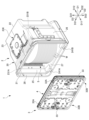
- FIG. 1 is an exploded perspective view showing a plurality of substrates W stored in a substrate storage container 1 according to an embodiment of the present invention.
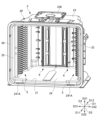
- 1 is a perspective view showing a container body 2 of a substrate storage container 1 according to an embodiment of the present invention.
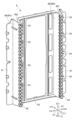
- FIG. 3 is a perspective view showing a lid 3 of the substrate storage container 1 according to an embodiment of the present invention.
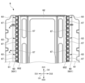
- FIG. 3 is a plan sectional view showing the positional relationship between the substrate storage container 1 and the substrates W in a closed state.
- FIG. 2 is a perspective view showing a front retainer 7 of the substrate storage container 1 according to an embodiment of the present invention.
- FIG. 2 is a partial front view showing the front retainer 7 of the substrate storage container 1 according to an embodiment of the present invention.
- FIG. 7 is a vertical cross-sectional view schematically showing a lid-side substrate support portion 73 of the front retainer 7.
- FIG. 7 is a vertical cross-sectional view schematically showing a substrate edge auxiliary portion 75 of the front retainer 7.
- FIG. 2 is a perspective view showing a rear retainer 6 of the substrate storage container 1 according to an embodiment of the present invention.
- FIG. 2 is a partial front view showing a rear retainer 6 of the substrate storage container 1 according to an embodiment of the present invention.
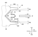
- 6A is a partially enlarged view of the vicinity of the left protruding wall portion 60 in FIG. 6A.
- FIG. 6B is a partially enlarged view of the vicinity of the left protruding wall portion 60 in FIG. 6B.
- FIG. 6 is a vertical cross-sectional view schematically showing a back board support part 63 and a board edge auxiliary part 65 of the rear retainer 6.
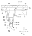
- FIG. 5 is a partially enlarged view of the vicinity of the left protruding wall portion 60 in FIG. 4.
- FIG. 6B is a cross-sectional view taken along the line AA shown in FIG. 6B.
- FIG. 1 is an exploded perspective view showing a plurality of substrates W stored in a substrate storage container 1 according to an embodiment of the present invention.
- FIG. 2 is a perspective view showing the container body 2 of the substrate storage container 1 according to an embodiment of the present invention.
- FIG. 3 is a perspective view showing the lid 3 of the substrate storage container 1 according to an embodiment of the present invention.
- FIG. 4 is a plan sectional view showing the positional relationship between the substrate storage container 1 and the substrates W in a closed state.
- the direction from the container body 2 to the lid 3 (direction from the upper right to the lower left in FIG. 1), which will be described later, is defined as the front direction D11 or front side D11, and the opposite direction is defined as the rear direction D12 or This is defined as the rear side D12, and these together are defined as the front-rear direction D1.
- the direction from the lower wall 24 to the upper wall 23 (upward direction in FIG. 1), which will be described later, is defined as an upper direction D21 or upper side D21, and the opposite direction is defined as a lower direction D22 or lower side D22. are collectively defined as the vertical direction D2.
- the direction from the second side wall 26 to the first side wall 25 is defined as a left direction D31, and the opposite direction is defined as a right direction D32. are collectively defined as the left-right direction D3 or the lateral direction D3. Some figures depict arrows indicating these directions.
- the substrate W (see FIG. 1) stored in the substrate storage container 1 is a disk-shaped silicon wafer, glass wafer, sapphire wafer, etc., and is a thin substrate used in industry.
- the substrate W in this embodiment is a silicon wafer with a diameter of 300 mm.
- a substrate storage container 1 is used to store a substrate W made of a silicon wafer as described above, and to transport the substrate W by means of transportation such as land transportation means, air transportation means, and marine transportation means. It is used as a shipping container, and includes a container body 2 and a lid 3.
- the container body 2 includes a substrate support plate portion 5 as a side substrate support portion and a rear retainer 6.
- the lid 3 includes a front retainer 7 (see FIGS. 3 to 5D) having a lid-side substrate support portion 73 and a substrate edge auxiliary portion 75.
- the container body 2 has a cylindrical wall portion 20 with a container body opening 21 formed at one end and closed at the other end.
- a substrate storage space 27 is formed within the container body 2.
- the substrate storage space 27 is surrounded by the wall portion 20 .
- a substrate support plate-shaped portion 5 is disposed in a portion of the wall portion 20 that forms the substrate storage space 27.
- the substrate storage space 27 can accommodate a plurality of substrates W.
- the substrate support plate-like portions 5 are provided on the wall portion 20 so as to form a pair within the substrate storage space 27.
- the substrate support plate-shaped portion 5 contacts the edges of the plurality of substrates W, thereby supporting the adjacent substrates W. It is possible to support the edges of a plurality of substrates W in a state in which they are spaced apart from each other at a predetermined interval and arranged in parallel.
- a rear retainer 6 is provided on a back wall 22 (described later) of a wall portion 20 of the container body 2.
- the rear retainer 6 (see FIG. 2, etc.) is provided on the wall portion 20 in the board storage space 27 so as to form a pair with a front retainer 7, which will be described later.
- the rear retainer 6 contacts the edges of the plurality of substrates W when the container main body opening 21 is closed by the lid 3 (in the closed state).
- the rear part can be supported.
- the lid 3 is attachable to and detachable from the opening peripheral portion 28 (see FIG. 1, etc.) that forms the container main body opening 21, and is capable of closing the container main body opening 21.
- the front retainer 7 is provided in a portion of the lid 3 that faces the substrate storage space 27 when the container main body opening 21 is closed by the lid 3.
- the front retainer 7 is arranged to form a pair with the rear retainer 6 inside the board storage space 27.
- the front retainer 7 when the container main body opening 21 is closed by the lid 3, the front retainer 7 is moved in front of the edges of the plurality of substrates W by abutting against the edges of the plurality of substrates W. can support the section.
- the front retainer 7 supports the plurality of substrates W in cooperation with the rear retainer 6 when the container main body opening 21 is closed by the lid 3, thereby separating adjacent substrates W at a predetermined interval. and hold them in parallel.
- the substrate storage container 1 is made of resin such as a plastic material, and examples of the resin material include polycarbonate, cycloolefin polymer, polyetherimide, polyether ketone, polybutylene terephthalate, polyether ether ketone, and liquid crystal.
- the resin material include polycarbonate, cycloolefin polymer, polyetherimide, polyether ketone, polybutylene terephthalate, polyether ether ketone, and liquid crystal.
- thermoplastic resins such as polymers and alloys thereof.
- electrically conductive substances such as carbon fibers, carbon powder, carbon nanotubes, and electrically conductive polymers are selectively added. It is also possible to add glass fiber, carbon fiber, etc. to increase rigidity.
- the wall portion 20 of the container body 2 includes a back wall 22, an upper wall 23, a lower wall 24, a first side wall 25, and a second side wall 26.
- the back wall 22, the upper wall 23, the lower wall 24, the first side wall 25, and the second side wall 26 are made of the above-mentioned materials and are integrally molded.
- the first side wall 25 and the second side wall 26 are opposed to each other, and the upper wall 23 and lower wall 24 are opposed to each other.
- the rear end of the upper wall 23 , the rear end of the lower wall 24 , the rear end of the first side wall 25 , and the rear end of the second side wall 26 are all connected to the back wall 22 .
- the front end of the upper wall 23, the front end of the lower wall 24, the front end of the first side wall 25, and the front end of the second side wall 26 have a positional relationship facing the back wall 22, and the container main body opening 21 has a substantially rectangular shape.
- An opening peripheral portion 28 is formed.
- the opening peripheral portion 28 is provided at one end of the container body 2, and the back wall 22 is located at the other end of the container body 2.
- the outer shape of the container body 2 formed by the outer surface of the wall portion 20 is box-shaped.
- the inner surface of the wall portion 20, that is, the inner surface of the back wall 22, the inner surface of the upper wall 23, the inner surface of the lower wall 24, the inner surface of the first side wall 25, and the inner surface of the second side wall 26 is a substrate storage space surrounded by these. 27 is formed.
- the container body opening 21 formed in the opening peripheral portion 28 communicates with a substrate storage space 27 surrounded by the wall portion 20 and formed inside the container body 2.
- the substrate storage space 27 can accommodate up to 25 substrates W.
- latch engagement recesses 231A and 231B recessed toward the outside of the board storage space 27 are provided in the upper wall 23 and the lower wall 24 near the opening periphery 28. , 241A, and 241B are formed. A total of four latch engagement recesses 231A, 231B, 241A, and 241B are formed, one each near the left and right ends of the upper wall 23 and the lower wall 24.
- a top flange 236 is fixed to the center of the upper wall 23.
- the top flange 236 is a member that becomes a part of the substrate storage container 1 that is hung and suspended when the substrate storage container 1 is suspended in an AMHS (automatic wafer transfer system), a PGV (wafer substrate transfer vehicle), or the like.
- the substrate support plate-like portions 5 are provided integrally with the first side wall 25 and the second side wall 26, respectively, and are arranged in pairs in the left-right direction D3. Note that the substrate support plate-shaped portion 5 may be separate from the first side wall 25 and the second side wall 26.
- the substrate support plate-shaped portion 5 has a plate-like substantially arc shape.
- a total of 50 substrate support plate-shaped portions 5 are provided on each of the first side wall 25 and the second side wall 26, with 25 substrate supporting plate portions 5 in the vertical direction D2.
- Adjacent substrate support plate-like portions 5 are arranged parallel to each other and spaced apart from each other by 10 mm to 12 mm in the vertical direction D2.
- another plate-shaped member is arranged above the uppermost substrate support plate-shaped part 5 in parallel with the substrate support plate-shaped part 5. This is a member that serves as a guide for the uppermost board W to be inserted into the board storage space 27 during insertion.
- the 25 substrate support plate-like portions 5 provided on the first side wall 25 and the 25 substrate support plate-like portions 5 provided on the second side wall 26 are in a positional relationship in which they face each other in the left-right direction D3.
- the 50 substrate support plate-like portions 5 and a member serving as a plate-like guide parallel to the substrate support plate-like portion 5 have a positional relationship parallel to the inner surface of the lower wall 24 .
- a convex portion is provided on the upper surface of the substrate support plate-like portion 5.
- the substrate W supported by the substrate support plate-like part 5 contacts only the protruding end of the convex part, and does not contact the substrate support plate-like part 5 in a planar manner.
- the substrate support plate-shaped portion 5 supports the edges of the plurality of substrates W in a state in which adjacent substrates W among the plurality of substrates W are spaced apart from each other by a predetermined interval and are positioned parallel to each other. It is possible.
- the rear retainer 6 is an interior component that is fixed (attached) to the back wall 22 of the container body 2 and arranged within the board storage space 27. Details of the rear retainer 6 will be described later. Note that instead of attaching the rear retainer 6 to the container body 2, the rear retainer 6 and the container body 2 are integrally constructed by insert molding or the like, so that the rear retainer 6 is attached to the back wall 22 of the container body 2. It may also be in a form where it is placed.
- FIG. 5A is a perspective view showing the front retainer 7 of the substrate storage container 1 according to an embodiment of the present invention.
- FIG. 5B is a partial front view showing the front retainer 7 of the substrate storage container 1 according to an embodiment of the present invention.
- FIG. 5C is a vertical cross-sectional view schematically showing the lid-side substrate support portion 73 of the front retainer 7.
- FIG. 5D is a vertical cross-sectional view schematically showing the substrate edge auxiliary portion 75 of the front retainer 7.
- FIG. 5A is a perspective view showing the front retainer 7 of the substrate storage container 1 according to an embodiment of the present invention.
- FIG. 5B is a partial front view showing the front retainer 7 of the substrate storage container 1 according to an embodiment of the present invention.
- FIG. 5C is a vertical cross-sectional view schematically showing the lid-side substrate support portion 73 of the front retainer 7.
- FIG. 5D is a vertical cross-sectional view schematically showing the substrate edge auxiliary portion 75 of the front retain
- the lid body 3 has a substantially rectangular shape that substantially matches the shape of the opening peripheral portion 28 of the container body 2.
- the lid 3 is removable from the opening periphery 28 of the container main body 2, and by attaching the lid 3 to the opening periphery 28, the lid 3 can close the container main opening 21.
- An annular sealing member 4 is attached to the inner surface of the lid 3 (the back surface of the lid 3 shown in FIG. 1).
- the sealing member 4 is made of various thermoplastic elastomers such as elastically deformable polyester and polyolefin, fluororubber, silicone rubber, and the like.
- the seal member 4 is arranged so as to go around the outer peripheral edge of the lid body 3.
- the sealing member 4 When the lid 3 is attached to the opening periphery 28 , the sealing member 4 is sandwiched between the opening periphery 28 and the inner surface of the lid 3 and elastically deforms, and the lid 3 closes the container body opening 21 . Closed in a sealed state. By removing the lid 3 from the opening peripheral portion 28, the substrate W can be taken in and out of the substrate storage space 27 within the container body 2.
- the lid body 3 has a lid body that forms the outer shape of the lid body 3, and the lid body is provided with a latch mechanism.
- the latch mechanism is provided near both left and right ends of the lid body, and as shown in FIG. It includes two lower latch parts 32B that can protrude from the lower side in the downward direction D22.
- the two upper latch parts 32A are arranged near both left and right ends of the upper side of the lid body, and the two lower latch parts 32B are arranged near both left and right ends of the lower side of the lid body.
- An operating section 33 is provided on the outer surface side of the lid body.
- the upper latch portion 32A and the lower latch portion 32B can be made to protrude from the upper and lower sides of the lid body, or can be prevented from protruding from the upper and lower sides. can do.
- the upper latch portion 32A protrudes upward from the upper side of the lid main body in the upward direction D21 and engages with the latch engagement recesses 231A and 231B of the container main body 2, and the lower latch portion 32B protrudes downward from the lower side of the lid main body.
- the lid body 3 is fixed to the opening peripheral portion 28 of the container body 2.
- a recess 34 is formed which is recessed toward the outside of the substrate storage space 27 (in the front direction D11).
- a front retainer 7 is fixed (attached) to a portion of the lid main body inside the recess 34 .
- the front retainer 7 includes a lid-side substrate support portion 73, a substrate edge auxiliary portion 75, leg portions 72, and a vertical frame 71.
- the lid side substrate support part 73 and the substrate edge auxiliary part 75 that correspond to the same substrate W are connected via the leg part 72.
- Two lid-side substrate support portions 73 are arranged in pairs, spaced apart at a predetermined interval in the left-right direction D3.
- the two lid-side substrate support parts 73 arranged in pairs in this way are provided in 25 pairs in parallel in the vertical direction D2, and each is supported by an elastically deformable leg part 72.
- the leg portions 72 extend outward in the lateral direction D3 so as to be spaced apart from each other from the two lid side substrate support portions 73, and are bent toward the front direction D11.
- a vertical frame 71 extending in parallel along the vertical direction D2 is integrally formed with the leg 72 at the outer end of the leg 72 in the lateral direction D3.
- the lid-side substrate support section 73 uses the elastic force of the legs 72 to move the edge of the substrate W into the substrate storage space. It is held and supported while being biased toward the center of 27.
- the lid-side substrate support section 73 has an upper inclined surface 731 and a lower inclined surface 732.
- the upper inclined surface 731 comes into contact with the edge of the front surface (top surface) of the substrate W when the container main body opening 21 is closed by the lid 3.
- the lower inclined surface 732 contacts the edge of the back surface (lower surface) of the substrate W.
- the upper inclined surface 731 is formed of an inclined surface that extends in the upward direction D21 so as to approach the center of the substrate storage space 27 in the front-rear direction D1.
- the lower inclined surface 732 is formed of an inclined surface that extends in an inclined direction away from the center of the substrate storage space 27 in the front-rear direction D1 as it advances in the upward direction D21.
- the upper inclined surface 731 and the lower inclined surface 732 form a V-shaped groove 74 which is a recessed groove spaced apart from the center of the substrate storage space 27 .
- Two board edge auxiliary parts 75 are arranged in pairs at a predetermined interval in the left-right direction D3.
- the two board edge auxiliary parts 75 arranged in pairs in this manner are provided in 25 pairs in parallel in the vertical direction D2, and are supported by the leg parts 72, respectively.
- the board edge auxiliary part 75 is arranged between the lid-side board support part 73 and the vertical frame 71 in the left-right direction D3.
- the substrate edge auxiliary portion 75 is disposed in a portion of the lid 3 that faces the substrate storage space 27 when the container main body opening 21 is closed by the lid 3. As shown in FIG. 5D, a plurality of auxiliary grooves 76 having an opening wider than the thickness of the edge of the substrate W are formed in the substrate edge auxiliary portion 75 so that the edge of the substrate W can be inserted therein.
- the groove forming surface forming the auxiliary groove 76 has a front facing surface portion 761, a back facing surface portion 762, and a bottom surface portion 763.
- the edge of the substrate W is connected to the edge of the substrate W and the groove forming surface of the auxiliary groove 76 (front surface facing surface portion 761, back surface facing surface portion 762, bottom surface portion). 763), and the edge of the substrate W is inserted into the auxiliary groove 76 in a non-contact state where it is not in contact with the groove forming surface.
- the auxiliary groove 76 has a substantially rectangular shape in cross-sectional view.
- the auxiliary groove 76 has opposing groove forming surfaces (a front facing surface portion 761 and a back facing surface portion 762).
- the edges of the plurality of substrates W are inserted one by one into the auxiliary groove 76 at least when the container main body opening 21 is closed by the lid 3.
- the auxiliary groove 76 is arranged on the outer side of the edge of the substrate W in the circumferential direction DC than the lid-side substrate support portion 73 with respect to the central axis J20 (see FIG. 4) of the cylindrical wall portion 20. .
- the surface-facing surface portion 761 has a positional relationship substantially parallel to the surface W1 of the substrate W when the container body opening 21 is closed by the lid 3, and a portion of the surface-facing surface portion 761 is substantially parallel to the surface W1 of the substrate W. It faces the front surface W1 in the vertical direction D2, which is the direction connecting W1 and the back surface W2.
- the back facing surface portion 762 has a positional relationship substantially parallel to the back surface W2 of the substrate W when the container main body opening 21 is closed by the lid 3, and a portion of the back facing surface portion 762 is It faces the back surface W2 in the up-down direction D2, which is the direction connecting W1 and the back surface W2.
- the bottom portion 763 forms the bottom of the auxiliary groove 76 and is connected to the front facing surface portion 761 and the back facing surface portion 762, respectively.
- the front facing surface portion 761 and the back facing surface portion 762 have a substantially straight planar shape.
- the front facing surface portion 761 and the back facing surface portion 762 constitute a pair of sloped surfaces that are slightly inclined so that the opening 764 slightly widens as it approaches the opening 764 of the auxiliary groove 76 from the bottom of the auxiliary groove 76.
- the angle ⁇ 71 between the front surface W1 and the front facing surface portion 761 of the substrate W, and/or the angle ⁇ 72 between the back surface W2 and the back facing surface portion 762 are, for example, 30 degrees or less, preferably 15 degrees or less.
- the auxiliary groove 76 is used as an auxiliary groove when the container main body opening 21 is not closed by the lid 3 and the edges of the plurality of substrates W are supported by the substrate support plate-like part 5 which is a side substrate support part.
- the depth H76 is such that the edge of the substrate W is inserted into the auxiliary groove 76.
- the depth H76 of the auxiliary groove 76 is, for example, 3.5 mm or more, preferably 4.5 mm or more, and more preferably 4.5 to 6.0 mm.
- FIG. 6A is a perspective view showing the rear retainer 6 of the substrate storage container 1 according to an embodiment of the present invention.
- FIG. 6B is a partial front view showing the rear retainer 6 of the substrate storage container 1 according to an embodiment of the present invention.
- FIG. 7A is a partially enlarged view of the vicinity of the protruding wall portion 60 on the left side of FIG. 6A.
- FIG. 7B is a partially enlarged view of the vicinity of the protruding wall portion 60 on the left side of FIG. 6B.
- FIG. 7C is a vertical cross-sectional view schematically showing the back board support part 63 and the board edge auxiliary part 65 of the rear retainer 6.
- FIG. 8 is a partially enlarged view of the vicinity of the protruding wall portion 60 on the left side of FIG. 4.
- FIG. 9 is a cross-sectional view taken along the line AA shown in FIG. 6B.
- the rear retainer 6 has a protruding wall portion 60, a back board support portion 63, a board edge auxiliary portion 65, an inner frame 62, an outer frame 61, and a circulation hole 67. .
- the protruding wall portion 60 is configured such that an outer surface 605 (see FIG. 8) protrudes toward the container main body opening 21 (that is, toward the front side D11) and an inner surface 606 (see FIG. 8) is recessed toward the container main body opening 21. It is a curved wall.
- the inner surface 606 is typically a surface on the side of the back wall 22 of the container body 2 or a surface facing the back wall 22 of the container body 2.
- the protruding wall portion 60 is an integral wall portion extending in the vertical direction D2. Two protruding wall portions 60 are arranged in pairs in the left-right direction D3 at a predetermined interval.
- Twenty-five back side board support parts 63 are provided on the protruding side of the protruding wall part 60 (that is, the front side D11) in a state where they are lined up in the vertical direction D2.
- the back side board support part 63 on the left side 31 and the back side board support part 63 on the right side 32 are arranged as a pair and spaced apart at a predetermined interval in the left-right direction D3.
- the rear substrate support parts 63 arranged in pairs in the left-right direction D3 are provided in 25 pairs in parallel in the up-down direction D2.
- the protruding wall portion 60 includes an outer wall portion 601, an inner wall portion 602, and a front wall portion 603.
- the outer wall portion 601 is an outer wall portion of the protruding wall portion 60 in the lateral direction D3.
- the inner wall portion 602 is an inner wall portion of the protruding wall portion 60 in the lateral direction D3.
- the front wall portion 603 is a wall portion that connects the outer wall portion 601 and the inner wall portion 602, and is a wall portion on the front side D11 of the protruding wall portion 60.
- a rear substrate support portion 63 and a substrate edge auxiliary portion 65 are provided almost entirely on the front side of the front wall portion 603 .
- the outer wall 601, inner wall 602, and front wall 603 of the protruding wall 60 are all flat.
- the shape of the protruding wall portion 60 is not limited.
- the protruding wall portion 60 may have a substantially V-shape when viewed from above, in which the front wall portion 603 is substantially absent.
- the protruding wall portion 60 may have a curved plate shape instead of a flat plate shape.
- the inner frame 62 is a part that connects and supports the back board support part 63 on the left side D31 and the back board support part 63 on the right side D32.
- the outer frames 61 are integrally provided on both outer sides of the protruding wall portion 60 in the lateral direction D3. By engaging the outer frame 61 with the wall portion 20 of the container body 2, the rear retainer 6 is fixed (attached) to the container body 2.
- the back substrate support part 63 supports the edge of the substrate W by sandwiching it.
- the back substrate support portion 63 has an upper inclined surface 631 and a lower inclined surface 632, as shown in FIGS. 7A to 7C.
- the upper inclined surface 631 comes into contact with the edge of the front surface (upper surface) of the substrate W when the container main body opening 21 is closed by the lid 3.
- the lower inclined surface 632 contacts the edge of the back surface (lower surface) of the substrate W.
- the upper inclined surface 631 is formed of an inclined surface that extends in the upward direction D21 so as to approach the center of the substrate storage space 27 in the front-rear direction D1.
- the lower inclined surface 632 is formed of an inclined surface that extends in an inclined direction away from the center of the substrate storage space 27 in the front-rear direction D1 as it advances in the upward direction D21.
- the back substrate support section 63 has a V-shaped groove 64 having a lower inclined surface 632 arranged on the lower side and an upper inclined surface 631 arranged on the upper side. Be prepared.
- the upper inclined surface 631 and the lower inclined surface 632 form a V-shaped groove 64 which is a recessed groove spaced apart from the center of the substrate storage space 27 .
- the upper inclined surface 631 and the lower inclined surface 632 are provided with an edge of the front surface W1 of the substrate W and an edge of the back surface W2 of the substrate W, respectively, when the container main body opening 21 is closed by the lid 3. come into contact with
- the V-shaped groove 64 supports the edge of the substrate W. Note that the V-shaped groove 64 only needs to be approximately V-shaped when viewed as a whole, and may additionally have a surface approximately parallel to the D1-D3 plane, a surface approximately parallel to the D2-D3 plane, etc. You can.
- a communication hole 67 is provided so as to pass through the front wall 603 and the rear substrate support 63 of the protruding wall 60.
- the communication hole 67 is a through hole extending in the front-rear direction D1. Note that the direction in which the communication hole 67 extends is not limited.
- liquid such as water
- the container body opening 21 of the container body 2 is generally turned downward. In this case, the protruding side of the protruding wall portion 60 of the rear retainer 6 is directed downward.
- the communication hole 67 is a hole for discharging the liquid located on the inner surface 606 side of the protruding wall 60 when the protruding side of the protruding wall 60 is facing downward.
- the communication hole 67 extends in the vertical direction D2 so as to penetrate the back substrate support portion 63. Therefore, in this embodiment, part or all of the liquid located on the inner surface 606 side of the protruding wall portion 60 is discharged via the communication hole 67.
- the communication hole 67 is a hole for increasing the area where the inner surface 606 side and the outer surface 605 side of the protruding wall portion 60 communicate with each other to improve air permeability (ventilation performance). Therefore, in this embodiment, the inner surface 606 side of the protruding wall portion 60 is easily dried.
- one communication hole 67 is provided in one back substrate support portion 63 .
- the area of one communication hole 67 is, for example, 30.5 mm 2 or more, preferably 30.5 to 40 mm 2 .
- Two board edge auxiliary parts 65 are arranged in pairs at a predetermined interval in the left-right direction D3.
- the board edge auxiliary part 65 is provided on the front side D11 of the back board support part 63.
- 25 of the board edge auxiliary parts 65 arranged in pairs in the left-right direction D3 are arranged in the up-down direction D2, similar to the back board support parts 63.
- the back side substrate support part 63 and the substrate edge auxiliary part 65 are arranged at positions facing the front retainer 7 when the container main body opening 21 is closed by the lid 3. has been done.
- a plurality of auxiliary grooves 66 having openings wider than the thickness of the edge of the substrate W are formed in the substrate edge auxiliary portion 65 so that the edge of the substrate W can be inserted therein.
- the groove forming surface forming the auxiliary groove 66 has a front facing surface portion 661 and a back facing surface portion 662.
- the edge of the substrate W is connected to the groove forming surface (front surface facing surface portion) 661 of the auxiliary groove 66 and the groove forming surface (back surface facing surface portion). Since a space is formed between the substrate W and the surface portion 662, the edge of the substrate W is inserted into the auxiliary groove 66 without contacting the groove forming surface.
- the surface-facing surface portion 661 has a positional relationship that is approximately parallel to the surface W1 of the substrate W when the container body opening 21 is closed by the lid 3, and a portion of the surface-facing surface portion 661 is substantially parallel to the surface W1 of the substrate W. It faces the front surface W1 in the vertical direction D2, which is the direction connecting W1 and the back surface W2.
- the back facing surface portion 662 has a positional relationship substantially parallel to the back surface W2 of the substrate W when the container body opening 21 is closed by the lid 3, and a portion of the back facing surface portion 662 is It faces the back surface W2 in the up-down direction D2, which is the direction connecting W1 and the back surface W2.
- the front facing surface portion 661 and the back facing surface portion 662 have a substantially straight planar shape.
- the front facing surface portion 661 and the back facing surface portion 662 are a pair of sloped surfaces that are slightly inclined so that the opening 664 of the auxiliary groove 76 becomes slightly wider as it approaches the opening 664 of the auxiliary groove 76 from the bottom of the auxiliary groove 66 (back side D12).
- the angle ⁇ 61 between the front surface W1 of the substrate W and the front facing surface portion 661 and/or the angle ⁇ 62 between the back surface W2 and the back facing surface portion 662 are, for example, 30 degrees or less, preferably 15 degrees or less.
- the auxiliary groove 66 is used as an auxiliary groove when the container main body opening 21 is not closed by the lid 3 and the edges of the plurality of substrates W are supported by the substrate support plate-shaped part 5 which is a side substrate support part.
- the depth H66 is such that the edge of the substrate W is inserted into the auxiliary groove 66.
- the depth H66 of the auxiliary groove 66 is, for example, 8 to 10.5 mm, preferably 8 to 20 mm.
- the depth H66 of the auxiliary groove 66 is preferably longer than the depth H76 of the auxiliary groove 76 of the front retainer 7, more preferably 14 mm or more.
- the groove forming surfaces 661 and 662 of the auxiliary groove 66 are arranged between the V-shaped grooves 64 and 64 of the back substrate support part 63 adjacent to each other in the vertical direction D2. be done. That is, the arrangement of the groove forming surface (front facing surface portion) 661, the V-shaped groove 64, and the groove forming surface (back facing surface portion) 662 is repeated from top to bottom.
- the protruding portion 68 is formed on the surface facing surface portion 661 of the auxiliary groove 66 of the substrate edge auxiliary portion 65 , the lower inclined surface 632 of the back substrate support portion 63 , and the lower slope surface 632 of the back substrate support portion 63 . It is provided across the upper inclined surface 631.
- the protruding portion 68 protrudes in the direction away from the surface, and includes a first protruding portion 681, a second protruding portion 682, and a third protruding portion 683.
- the first protruding portion 681 is provided on the inner edge in the lateral direction D3 of the back surface opposing surface portion 662 of the auxiliary groove 66 of the substrate edge auxiliary portion 65.
- the first protruding portion 681 is formed on the inner side in the lateral direction D3 of the back facing surface portion 662, which is a groove forming surface disposed on the lower side D22 of the auxiliary groove 66.
- This is a protruding strip that projects in the direction D21 and extends from the container main body opening 21 toward the back wall 22 of the wall 20.
- the second protruding portion 682 is provided on the inner edge of the lower inclined surface 632 of the back substrate support portion 63 in the lateral direction D3.
- the second convex strip 682 protrudes inward in the lateral direction D3 of the lower inclined surface 632 in the upward direction D21, and extends from the container main body opening 21 to the wall portion 20. This is a convex strip extending toward the back wall 22.
- the third protruding portion 683 is provided on the inner edge of the upper inclined surface 631 of the back substrate support portion 63 in the lateral direction D3.
- the first protruding portion 681, the second protruding portion 682, and the third protruding portion 683 are continuous.
- the rear retainer 6 is fixed to the container body 2 such that there is a gap G6 between the rear retainer 6 and the back wall 22 of the wall portion 20 of the container body 2.
- the back surface side (the side facing the back wall 22; the back side D12) of the rear retainer 6 is not flat, but has a gap forming protrusion 621 that protrudes toward the rear direction D12.
- the gap forming protrusion 621 forms a gap G6 between the back wall 22 of the container body 2 and the flat portion of the back surface of the rear retainer 6.
- the size of the gap G6 is, for example, 4 mm or more, preferably 4 to 6 mm. Note that the configuration for forming the gap G6 is not limited.
- the gap G6 may be formed by a protrusion provided on the back wall 22 of the container body 2.
- the container body 2 is arranged so that the front-rear direction D1 and the left-right direction D3 are parallel to a horizontal plane.
- a plurality of substrates W are placed on the lower inclined surface 632 of the substrate support plate-like part 5 and the back substrate support part 63.
- the substrate W is not located in the V-shaped groove 74 of the lid side substrate support part 73 and the auxiliary groove 76 of the substrate edge auxiliary part 75 (does not overlap in plan view).
- the lid body 3 is brought closer to the container main body opening 21, and brought into contact with the lower side inclined surface 732 of the front retainer 7 and the edge of the back surface (lower surface) of the substrate W, and the upper side of the front retainer 7
- the inclined surface 731 is brought into contact with the edge of the front surface of the substrate W.
- the substrate W is pressed in the rear direction D12 by the lower inclined surface 732 and the upper inclined surface 731 of the front retainer 7 at the front part, and It is pressed in the front direction D11 by coming into contact with the back side substrate support part 63 at the rear part, and is held so as to be sandwiched between the front direction D11 and the rear direction D12.
- the substrate W moves in the vertical direction D2 with respect to its back side (rear side D12), and does not move in the vertical direction D2 with respect to its opening side (front direction D11 side). At this time, the substrate W is located in the auxiliary groove 76 of the substrate edge auxiliary portion 75 (overlapping in plan view).
- the substrate storage container 1 is either rotated 90 degrees and transported with the container body opening 21 facing vertically upward, or alternatively, the substrate storage container 1 is not rotated 90 degrees and is transported with the container body opening 21 facing vertically upward. 21 is conveyed with it facing horizontally.
- the substrate storage container 1 will come into contact with the V-shaped groove 74 of the lid-side substrate support portion 73.
- the substrate W may come off from the V-shaped groove 74.
- the substrate W does not come into contact with the auxiliary groove 76 of the substrate edge auxiliary part 75, so it is difficult to come off from the auxiliary groove 76 of the substrate edge auxiliary part 75.
- the substrate W that was in contact with the V-shaped groove 64 of the back side substrate support part 63 is about to come off from the V-shaped groove 64.
- the substrate W does not come into contact with the auxiliary groove 66 of the substrate edge auxiliary part 65, so it is difficult to come off from the auxiliary groove 66 of the substrate edge auxiliary part 65. Therefore, the substrate W is prevented from coming off the lid-side substrate support section 73 and/or the back-side substrate support section 63, that is, the occurrence of cross slots is suppressed.
- the substrate storage container 1 includes a cylindrical wall portion 20 having a container body opening 21 formed at one end and closed at the other end, and the inner surface of the wall portion 20 stores a plurality of substrates W.
- a container body 2 that can be stored and has a board storage space 27 that communicates with the container body opening 21 , and a lid 3 that is detachable from the container body opening 21 and can close the container body opening 21 .
- the lid 3 includes a lid-side substrate support part 73 that can support the edges of a plurality of substrates W when the substrates are in use, and a rear retainer 6.
- the rear retainer 6 is disposed in a pair with the lid-side substrate support part 73 in the substrate storage space 27 and can support the edges of a plurality of substrates W, and the container main body opening 21 is closed by the lid 3.
- the inner substrate support part 63 supports the plurality of substrates W in a state in which the edges of the plurality of substrates W are aligned in parallel by cooperating with the lid side substrate support part 73 while the outer surface 605 is connected to the container body.
- a protruding wall portion 60 that protrudes toward the opening portion 21 and has an inner surface 606 recessed toward the container main body opening portion 21, and a protruding wall portion 60 in which a back substrate support portion 63 is provided on the protruding side of the protruding wall portion 60. and a communication hole 67 for allowing liquid and/or gas to flow, which is located on the inner surface 606 side of the protruding wall 60 when the protruding side of the protruding wall 60 is facing downward.
- the liquid located on the inner surface 606 side of the protruding wall portion 60 moves through the circulation hole 67 in the direction shown by the arrow DF (see FIG. 8), and moves on the side of the outer surface 605 of the protruding wall portion 60. easily discharged.
- the air permeability (ventilation performance) between the inner surface 606 side and the outer surface 605 side of the protruding wall portion 60 is high. Therefore, when cleaning the substrate storage container 1 with the rear retainer 6 disposed on the back wall 22 side of the substrate storage space 27 of the container body 2, insufficient drying on the inner surface 606 side of the rear retainer after cleaning can be improved. , there is no need to unnecessarily lengthen the drying process time, and an increase in production costs is suppressed.
- the communication hole 67 extends in the vertical direction so as to penetrate the back substrate support portion 63.
- the liquid located on the inner surface 606 side of the protruding wall section 60 smoothly passes through the circulation hole 67 directly downward, and is quickly discharged to the outer surface 605 side of the protruding wall section 60. .
- the rear retainer 6 is fixed to the container body 2 such that there is a gap G6 between the rear retainer 6 and the back wall 22 of the wall portion 20 of the container body 2.
- the liquid located between the rear retainer 6 and the back wall 22 of the wall 20 of the container main body 2 is not easily affected by capillarity, and the liquid located between the rear retainer 6 and the back wall 22 of the wall 20 of the container main body 2 is easily flows out from between (hard to remain during this time). Further, the space between the rear retainer 6 and the back wall 22 of the wall portion 20 of the container body 2 is easily dried.
- the back substrate support portion 63 has a V-shape having a lower inclined surface 632 disposed on the lower side D22 and an upper inclined surface 631 disposed on the upper side D21.
- a shaped groove 64 is provided.
- a groove is formed on the inside of the lower inclined surface 632 in the lateral direction D3, protrudes in the upward direction D21, and extends from the container main body opening 21 toward the back wall 22 of the wall 20.
- Two protruding stripes 682 are provided.
- the contact area between the back surface W2 of the substrate W and the lower inclined surface 632 of the back substrate support section 63 can be reduced. Therefore, when the container main body opening 21 is closed with the lid 3, the substrate W slides and rises against the lower inclined surface 632, and the edge of the substrate W is supported by the V-shaped groove 64. In the process, the sliding resistance between the back surface W2 of the substrate W and the lower inclined surface 632 of the back substrate support portion 63 can be reduced.
- the second protruding portion 682 is arranged on the inner side of the lower inclined surface 632 in the lateral direction D3, and is arranged at a position shifted from the communication hole 67 in the lateral direction D3.
- the second protruding portion 682 is less likely to inhibit the movement of the liquid that passes through the flow hole 67 and falls.
- the second protruding portion 682 does not easily hinder the degree of freedom of the mold cutting.
- the rear retainer 6 is disposed at a portion facing the substrate storage space 27 when the container main body opening 21 is closed by the lid body 3, and is arranged so that the edge of the substrate W can be inserted into the rear retainer 6. It further includes an auxiliary groove 66 having an opening 664 wider than the opening 664.
- the auxiliary groove 66 has opposing groove forming surfaces (a front facing surface portion 661 and a back facing surface portion 662), and at least when the container main body opening 21 is closed by the lid 3, the edges of the plurality of substrates W are inserted one by one.
- a space is formed between the edge of the substrate W and the groove forming surfaces 661, 662, and the edge of the substrate W is closed.
- the groove forming surfaces 661, 662 of the auxiliary groove 66 are It is arranged between the V-shaped grooves 64 of the back substrate support portions 63 adjacent to each other in the vertical direction D2.
- the groove forming surface 662 disposed on the lower side D22 of the auxiliary groove 66 protrudes inward in the lateral direction D3 and protrudes in the upper direction D21 from the container main body opening 21.
- a first protruding portion 681 extending toward the back wall 22 of the wall portion 20 is provided.
- the first protruding portion 681 is disposed inside the groove forming surface 662 disposed on the lower side D22 in the lateral direction D3, and is disposed at a position shifted from the communication hole 67 in the lateral direction D3.
- the first protruding portion 681 is less likely to inhibit the movement of the liquid that passes through the flow hole 67 and falls.
- the first protruding portion 681 does not easily hinder the degree of freedom of the mold cutting.
- the configurations of the side substrate support portions (substrate support plate-like portions 5), the front retainer 7, and the rear retainer 6 are not limited to the configurations of the embodiments.
- the substrate W in this embodiment was a silicon wafer with a diameter of 300 mm, it is not limited to this value.
- Substrate storage container 2 Container body 3 Lid body 5 Substrate support plate-shaped part (side substrate support part) 6 Rear retainer 21 Container body opening 22 Back wall 27 Board storage space 28 Opening periphery 60 Projecting wall 63 Back board support 64 V-shaped groove 65 Board edge auxiliary part 66 Auxiliary groove 67 Distribution hole 68 Convex strip 601 Outer wall 602 Inner wall 603 Front wall 605 Outer surface 606 Inner surface 631 Upper inclined surface 632 Lower inclined surface 661 Surface facing surface (groove forming surface) 662 Back side facing surface part (groove forming surface) 664 Opening 681 First protruding part 682 Second protruding part 683 Third protruding part 73 Lid side substrate support part 75 Substrate edge auxiliary part 76 Auxiliary groove 761 Surface facing surface part (groove forming surface) 762 Back side facing surface part (groove forming surface) D1 Front-rear direction D11 Front direction, front side D12 Back direction, rear side D2 Up-down
Landscapes
- Packaging Frangible Articles (AREA)
- Container, Conveyance, Adherence, Positioning, Of Wafer (AREA)
Priority Applications (6)
| Application Number | Priority Date | Filing Date | Title |
|---|---|---|---|
| PCT/JP2022/025312 WO2023248464A1 (ja) | 2022-06-24 | 2022-06-24 | 基板収納容器及びリアリテーナ |
| US18/878,482 US20260082855A1 (en) | 2022-06-24 | 2022-06-24 | Substrate housing container and rear retainer |
| JP2024528241A JPWO2023248464A1 (https=) | 2022-06-24 | 2022-06-24 | |
| CN202280094990.2A CN119054062A (zh) | 2022-06-24 | 2022-06-24 | 基板收纳容器以及后部保持构件 |
| KR1020247041092A KR20250026173A (ko) | 2022-06-24 | 2022-06-24 | 기판수납용기 및 리어 리테이너 |
| TW112123433A TW202401636A (zh) | 2022-06-24 | 2023-06-21 | 基板收納容器以及後部保持構件 |
Applications Claiming Priority (1)
| Application Number | Priority Date | Filing Date | Title |
|---|---|---|---|
| PCT/JP2022/025312 WO2023248464A1 (ja) | 2022-06-24 | 2022-06-24 | 基板収納容器及びリアリテーナ |
Publications (1)
| Publication Number | Publication Date |
|---|---|
| WO2023248464A1 true WO2023248464A1 (ja) | 2023-12-28 |
Family
ID=89379346
Family Applications (1)
| Application Number | Title | Priority Date | Filing Date |
|---|---|---|---|
| PCT/JP2022/025312 Ceased WO2023248464A1 (ja) | 2022-06-24 | 2022-06-24 | 基板収納容器及びリアリテーナ |
Country Status (6)
| Country | Link |
|---|---|
| US (1) | US20260082855A1 (https=) |
| JP (1) | JPWO2023248464A1 (https=) |
| KR (1) | KR20250026173A (https=) |
| CN (1) | CN119054062A (https=) |
| TW (1) | TW202401636A (https=) |
| WO (1) | WO2023248464A1 (https=) |
Cited By (2)
| Publication number | Priority date | Publication date | Assignee | Title |
|---|---|---|---|---|
| WO2025163816A1 (ja) * | 2024-01-31 | 2025-08-07 | ミライアル株式会社 | 基板収納容器 |
| WO2025253846A1 (ja) * | 2024-06-06 | 2025-12-11 | 信越ポリマー株式会社 | 基板収納容器 |
Citations (7)
| Publication number | Priority date | Publication date | Assignee | Title |
|---|---|---|---|---|
| JPH11251422A (ja) * | 1998-03-03 | 1999-09-17 | Shinko Electric Co Ltd | ウェーハ収納容器 |
| JP2007142192A (ja) * | 2005-11-18 | 2007-06-07 | Miraial Kk | 薄板体収納容器 |
| JP2016058425A (ja) * | 2014-09-05 | 2016-04-21 | 株式会社Screenホールディングス | 基板収納容器、ロードポート装置および基板処理装置 |
| JP2016072385A (ja) * | 2014-09-29 | 2016-05-09 | 株式会社Screenホールディングス | 基板収納容器、ロードポート装置および基板処理装置 |
| JP2016086161A (ja) * | 2014-10-24 | 2016-05-19 | ラム リサーチ コーポレーションLam Research Corporation | 排出流の方向が単一のバッファステーション |
| WO2018154779A1 (ja) * | 2017-02-27 | 2018-08-30 | ミライアル株式会社 | 基板収納容器 |
| US20210225676A1 (en) * | 2018-04-02 | 2021-07-22 | Bum Je WOO | Wafer storage container |
Family Cites Families (9)
| Publication number | Priority date | Publication date | Assignee | Title |
|---|---|---|---|---|
| US6776289B1 (en) * | 1996-07-12 | 2004-08-17 | Entegris, Inc. | Wafer container with minimal contact |
| US5992638A (en) * | 1998-11-11 | 1999-11-30 | Empak, Inc. | Advanced wafer shipper |
| JP4146718B2 (ja) * | 2002-12-27 | 2008-09-10 | ミライアル株式会社 | 薄板支持容器 |
| KR20110002268A (ko) * | 2009-07-01 | 2011-01-07 | 비아이 이엠티 주식회사 | 리테이너와 이를 이용한 웨이퍼 운송용 박스 |
| WO2016046985A1 (ja) * | 2014-09-26 | 2016-03-31 | ミライアル株式会社 | 基板収納容器 |
| TWI680525B (zh) * | 2014-12-18 | 2019-12-21 | 美商恩特葛瑞斯股份有限公司 | 具有衝擊狀態保護的晶圓容置盒 |
| CN112074944B (zh) * | 2018-04-25 | 2024-07-05 | 未来儿股份有限公司 | 基板收纳容器 |
| JP7313975B2 (ja) * | 2019-08-27 | 2023-07-25 | 信越ポリマー株式会社 | 基板収納容器 |
| JP7414982B2 (ja) * | 2020-05-19 | 2024-01-16 | ミライアル株式会社 | 基板収納容器 |
-
2022
- 2022-06-24 WO PCT/JP2022/025312 patent/WO2023248464A1/ja not_active Ceased
- 2022-06-24 CN CN202280094990.2A patent/CN119054062A/zh active Pending
- 2022-06-24 JP JP2024528241A patent/JPWO2023248464A1/ja active Pending
- 2022-06-24 KR KR1020247041092A patent/KR20250026173A/ko active Pending
- 2022-06-24 US US18/878,482 patent/US20260082855A1/en active Pending
-
2023
- 2023-06-21 TW TW112123433A patent/TW202401636A/zh unknown
Patent Citations (7)
| Publication number | Priority date | Publication date | Assignee | Title |
|---|---|---|---|---|
| JPH11251422A (ja) * | 1998-03-03 | 1999-09-17 | Shinko Electric Co Ltd | ウェーハ収納容器 |
| JP2007142192A (ja) * | 2005-11-18 | 2007-06-07 | Miraial Kk | 薄板体収納容器 |
| JP2016058425A (ja) * | 2014-09-05 | 2016-04-21 | 株式会社Screenホールディングス | 基板収納容器、ロードポート装置および基板処理装置 |
| JP2016072385A (ja) * | 2014-09-29 | 2016-05-09 | 株式会社Screenホールディングス | 基板収納容器、ロードポート装置および基板処理装置 |
| JP2016086161A (ja) * | 2014-10-24 | 2016-05-19 | ラム リサーチ コーポレーションLam Research Corporation | 排出流の方向が単一のバッファステーション |
| WO2018154779A1 (ja) * | 2017-02-27 | 2018-08-30 | ミライアル株式会社 | 基板収納容器 |
| US20210225676A1 (en) * | 2018-04-02 | 2021-07-22 | Bum Je WOO | Wafer storage container |
Cited By (2)
| Publication number | Priority date | Publication date | Assignee | Title |
|---|---|---|---|---|
| WO2025163816A1 (ja) * | 2024-01-31 | 2025-08-07 | ミライアル株式会社 | 基板収納容器 |
| WO2025253846A1 (ja) * | 2024-06-06 | 2025-12-11 | 信越ポリマー株式会社 | 基板収納容器 |
Also Published As
| Publication number | Publication date |
|---|---|
| KR20250026173A (ko) | 2025-02-25 |
| JPWO2023248464A1 (https=) | 2023-12-28 |
| CN119054062A (zh) | 2024-11-29 |
| TW202401636A (zh) | 2024-01-01 |
| US20260082855A1 (en) | 2026-03-19 |
Similar Documents
| Publication | Publication Date | Title |
|---|---|---|
| JP7414982B2 (ja) | 基板収納容器 | |
| TWI749205B (zh) | 基板收納容器 | |
| TWI602756B (zh) | Substrate storage container | |
| TWI796660B (zh) | 基板收納容器 | |
| TWI627117B (zh) | Substrate storage container | |
| KR102677319B1 (ko) | 기판 수납 용기 | |
| WO2023248464A1 (ja) | 基板収納容器及びリアリテーナ | |
| JP6106271B2 (ja) | 基板収納容器 | |
| JP7562657B2 (ja) | 基板収納容器 | |
| TW201703177A (zh) | 基板收納容器 | |
| JP7675173B2 (ja) | 基板収納容器 | |
| TW202032700A (zh) | 基板收納容器 | |
| KR102942671B1 (ko) | 기판수납용기 및 그 뚜껑 | |
| TW202435342A (zh) | 基板收納容器 | |
| TW202522658A (zh) | 基板收納容器 | |
| WO2025074498A1 (ja) | 基板収納容器 | |
| TW202447829A (zh) | 基板收納容器 | |
| JP2022003673A (ja) | 基板収納容器 |
Legal Events
| Date | Code | Title | Description |
|---|---|---|---|
| 121 | Ep: the epo has been informed by wipo that ep was designated in this application |
Ref document number: 22947065 Country of ref document: EP Kind code of ref document: A1 |
|
| ENP | Entry into the national phase |
Ref document number: 2024528241 Country of ref document: JP Kind code of ref document: A |
|
| WWE | Wipo information: entry into national phase |
Ref document number: 202280094990.2 Country of ref document: CN |
|
| WWE | Wipo information: entry into national phase |
Ref document number: 18878482 Country of ref document: US |
|
| NENP | Non-entry into the national phase |
Ref country code: DE |
|
| WWP | Wipo information: published in national office |
Ref document number: 1020247041092 Country of ref document: KR |
|
| 122 | Ep: pct application non-entry in european phase |
Ref document number: 22947065 Country of ref document: EP Kind code of ref document: A1 |
|
| WWP | Wipo information: published in national office |
Ref document number: 18878482 Country of ref document: US |