WO2023248386A1 - 充電システム、充電装置、及び充電制御方法 - Google Patents
充電システム、充電装置、及び充電制御方法 Download PDFInfo
- Publication number
- WO2023248386A1 WO2023248386A1 PCT/JP2022/024930 JP2022024930W WO2023248386A1 WO 2023248386 A1 WO2023248386 A1 WO 2023248386A1 JP 2022024930 W JP2022024930 W JP 2022024930W WO 2023248386 A1 WO2023248386 A1 WO 2023248386A1
- Authority
- WO
- WIPO (PCT)
- Prior art keywords
- charging
- connector
- inlet
- state
- switch
- Prior art date
- Legal status (The legal status is an assumption and is not a legal conclusion. Google has not performed a legal analysis and makes no representation as to the accuracy of the status listed.)
- Ceased
Links
Images



Classifications
-
- B—PERFORMING OPERATIONS; TRANSPORTING
- B60—VEHICLES IN GENERAL
- B60L—PROPULSION OF ELECTRICALLY-PROPELLED VEHICLES; SUPPLYING ELECTRIC POWER FOR AUXILIARY EQUIPMENT OF ELECTRICALLY-PROPELLED VEHICLES; ELECTRODYNAMIC BRAKE SYSTEMS FOR VEHICLES IN GENERAL; MAGNETIC SUSPENSION OR LEVITATION FOR VEHICLES; MONITORING OPERATING VARIABLES OF ELECTRICALLY-PROPELLED VEHICLES; ELECTRIC SAFETY DEVICES FOR ELECTRICALLY-PROPELLED VEHICLES
- B60L53/00—Methods of charging batteries, specially adapted for electric vehicles; Charging stations or on-board charging equipment therefor; Exchange of energy storage elements in electric vehicles
- B60L53/10—Methods of charging batteries, specially adapted for electric vehicles; Charging stations or on-board charging equipment therefor; Exchange of energy storage elements in electric vehicles characterised by the energy transfer between the charging station and the vehicle
- B60L53/14—Conductive energy transfer
- B60L53/16—Connectors, e.g. plugs or sockets, specially adapted for charging electric vehicles
-
- H—ELECTRICITY
- H01—ELECTRIC ELEMENTS
- H01R—ELECTRICALLY-CONDUCTIVE CONNECTIONS; STRUCTURAL ASSOCIATIONS OF A PLURALITY OF MUTUALLY-INSULATED ELECTRICAL CONNECTING ELEMENTS; COUPLING DEVICES; CURRENT COLLECTORS
- H01R13/00—Details of coupling devices of the kinds covered by groups H01R12/70 or H01R24/00 - H01R33/00
- H01R13/62—Means for facilitating engagement or disengagement of coupling parts or for holding them in engagement
- H01R13/639—Additional means for holding or locking coupling parts together, after engagement, e.g. separate keylock, retainer strap
-
- H—ELECTRICITY
- H01—ELECTRIC ELEMENTS
- H01R—ELECTRICALLY-CONDUCTIVE CONNECTIONS; STRUCTURAL ASSOCIATIONS OF A PLURALITY OF MUTUALLY-INSULATED ELECTRICAL CONNECTING ELEMENTS; COUPLING DEVICES; CURRENT COLLECTORS
- H01R13/00—Details of coupling devices of the kinds covered by groups H01R12/70 or H01R24/00 - H01R33/00
- H01R13/66—Structural association with built-in electrical component
- H01R13/70—Structural association with built-in electrical component with built-in switch
- H01R13/703—Structural association with built-in electrical component with built-in switch operated by engagement or disengagement of coupling parts, e.g. dual-continuity coupling part
-
- H—ELECTRICITY
- H02—GENERATION; CONVERSION OR DISTRIBUTION OF ELECTRIC POWER
- H02J—ELECTRIC POWER NETWORKS; CIRCUIT ARRANGEMENTS OR SYSTEMS FOR SUPPLYING OR DISTRIBUTING ELECTRIC POWER; SYSTEMS FOR STORING ELECTRIC ENERGY
- H02J7/00—Circuit arrangements for charging or discharging batteries or for supplying loads from batteries
-
- Y—GENERAL TAGGING OF NEW TECHNOLOGICAL DEVELOPMENTS; GENERAL TAGGING OF CROSS-SECTIONAL TECHNOLOGIES SPANNING OVER SEVERAL SECTIONS OF THE IPC; TECHNICAL SUBJECTS COVERED BY FORMER USPC CROSS-REFERENCE ART COLLECTIONS [XRACs] AND DIGESTS
- Y02—TECHNOLOGIES OR APPLICATIONS FOR MITIGATION OR ADAPTATION AGAINST CLIMATE CHANGE
- Y02T—CLIMATE CHANGE MITIGATION TECHNOLOGIES RELATED TO TRANSPORTATION
- Y02T10/00—Road transport of goods or passengers
- Y02T10/60—Other road transportation technologies with climate change mitigation effect
- Y02T10/70—Energy storage systems for electromobility, e.g. batteries
-
- Y—GENERAL TAGGING OF NEW TECHNOLOGICAL DEVELOPMENTS; GENERAL TAGGING OF CROSS-SECTIONAL TECHNOLOGIES SPANNING OVER SEVERAL SECTIONS OF THE IPC; TECHNICAL SUBJECTS COVERED BY FORMER USPC CROSS-REFERENCE ART COLLECTIONS [XRACs] AND DIGESTS
- Y02—TECHNOLOGIES OR APPLICATIONS FOR MITIGATION OR ADAPTATION AGAINST CLIMATE CHANGE
- Y02T—CLIMATE CHANGE MITIGATION TECHNOLOGIES RELATED TO TRANSPORTATION
- Y02T10/00—Road transport of goods or passengers
- Y02T10/60—Other road transportation technologies with climate change mitigation effect
- Y02T10/7072—Electromobility specific charging systems or methods for batteries, ultracapacitors, supercapacitors or double-layer capacitors
Definitions
- the charging device includes a lock unit that locks the connection state of the connector to the inlet, and a connection determination device that determines that the connector is connected to the inlet.
- the lock control unit may include a lock control unit that locks the connection state of the connector to the inlet when the lock unit determines that the connector is connected to the inlet.
- the charging device is a charging device that charges the battery of an electric vehicle, and includes a connector connectable to an inlet provided on the electric vehicle, and a semi-connected state of the connector to the inlet. a switch to detect; a connection determination unit that determines whether the connector is connected to the inlet based on a detection result of the switch; and a case where the connection determination unit determines that the connector is connected to the inlet. and a charging control unit that starts a charging operation for charging the battery.
- charging operation can be automatically started. Therefore, it is possible to charge an electric vehicle without time restrictions.
- the charging control method is a charging control method in a charging device that charges a battery of an electric vehicle, and includes a switch that detects a half-connected state of a connector of the charging device to an inlet of the electric vehicle. a step of obtaining a detection result; a step of determining whether the connector is connected to the inlet based on the obtained detection result of the switch; and when it is determined that the connector is connected to the inlet.
- the method includes the step of starting a charging operation to charge the battery. Thereby, when the connector is connected to the inlet, charging operation can be automatically started. Therefore, it is possible to charge an electric vehicle without time restrictions.
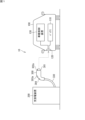
- the electric vehicle 100 includes a battery 110 for driving a driving motor (not shown). Electric vehicle 100 further includes an inlet 120 and an on-vehicle control device 130.
- the charging/discharging device 200 includes a connector 300 and a charging/discharging control device 350.
- Connector 300 is attachable to and detachable from inlet 120.
- the inlet 120 is an input/output port for power of the battery 110, and is connected to the battery 110 by a power line.
- the charging/discharging device 200 charges/discharges the battery 110 of the electric vehicle 100.
- the inlet 120 is connected to the on-vehicle control device 130 via a communication line.
- the in-vehicle control device 130 can communicate with the charging/discharging device 200 using a specific communication protocol.
- the in-vehicle control device 130 is capable of communication using CAN (Controller Area Network).
- the in-vehicle control device 130 is capable of communication using Ethernet (registered trademark).
- the connector 300 is provided at the tip of the cable 330 extending from the charge/discharge control device 350.
- Connector 300 has a plug 301 at its tip. Plug 301 can be inserted into a socket provided in inlet 120.
- the plug 301 is provided with a latch 302a.
- the latch 302a When the connector 300 is connected to the inlet 120, the latch 302a is caught on the inlet 120, and the latch 302a prevents the connector 300 from coming off from the inlet 120.
- the connector 300 is further provided with a release button 303a.
- Release button 303a is used to move latch 302a.
- the latch 302a moves and disengages from the inlet 120. The user can pull out the connector 300 from the inlet 120 while pressing the release button 303a.
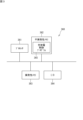
- FIG. 2 is a block diagram showing an example of the configuration of the charging/discharging device according to this embodiment.
- the charge/discharge control device 350 includes a control circuit 360, a communication interface (I/F) 351, a power converter 352, a battery 353, and a display 354.
- I/F communication interface
- the charging/discharging device 200 is, for example, a V2H (Vehicle to Home) device, and is placed at home.
- the power converter 352 is connected to a commercial AC power source 400, a load 410 that is an electrical device placed at home, and a battery 353.
- a power line 317 extends from the power converter 352 through the sheath of the cable 330 to the connector 300.
- the power converter 352 can charge the battery 110. That is, the power converter 352 can convert AC power from the commercial AC power supply 400 into DC power of a predetermined voltage, and output the DC power. The output DC power is applied to the battery 110 through the power line 317, and the battery 110 is charged. Furthermore, the power converter 352 can also convert the voltage of the DC power output from the battery 353 and output the converted DC power. Thereby, the battery 110 can be charged with the power stored in the battery 353.
- the power converter 352 can discharge the battery 110. That is, the power converter 352 converts the DC power output from the battery 110 into AC power, outputs the AC power to the load 410, or reversely flows the AC power to the grid-connected commercial AC power source 400. be able to. Furthermore, the power converter 352 can also convert the voltage of the DC power output from the battery 110 and output the converted DC power to the battery 353. Thereby, the battery 353 can be charged with the power stored in the battery 110.
- the present embodiment describes the charging/discharging system 10 that charges and discharges the battery 110 of the electric vehicle 100
- the present invention is not limited thereto.
- it may be a charging system that charges the battery 110 of the electric vehicle 100 using a charging device placed at a public charging station.
- the public charging device does not have a function of discharging the battery 110, but only has a function of charging it.
- the control circuit 351 is connected to the power converter 352 and controls the power converter 352. Control circuit 351 detects connection of connector 300 to inlet 120 and causes power converter 352 to perform charging/discharging operation for battery 110.
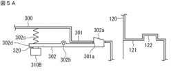
- a latch member 302 is arranged inside the connector 300.
- the latch member 302 is a lever rotatable about a fulcrum 302b.
- a first end of the latch member 302 protrudes upward to form a latch 302a.
- the second end of the latch member 302 is pushed downward by a spring 302c. This forces the latch 302a upward.
- a switch 310B is arranged below the latch 302a.
- the switch 310B is a b-contact microswitch.
- the switch 310B includes an actuator and a contact mechanism, and the contact mechanism opens and closes depending on the position of the actuator. That is, when the latch 302a is in the upper position (the natural position pushed by the spring 302c), the latch member 302 pushes the actuator and the switch 310B is in the OFF state. When the latch 302a is in the lower position (the position where the latch 302a is pushed down against the biasing force of the spring 302c), the latch member 302 does not press the actuator and the switch 310B is in the ON state.
- the "OFF state” of the switch 310B is an example of the "first state", and the "ON state” of the switch 310B is an example of the "second state”.
- Switch 310B is connected to control circuit 360 by signal line 314 passing through the sheath of cable 330. Control circuit 360 can receive an ON signal from switch 310B.
- the connector 300 has a built-in lock portion 303.
- the lock portion 303 locks the connection state between the connector 300 and the inlet 120.
- the lock portion 303 is an electromagnetic lock including a solenoid.
- the lock section 303 is connected to the control circuit 360 by a signal line 312 and operates according to a control signal from the control circuit 360. That is, when the lock section 303 receives a control signal, a current is applied to the solenoid, and the movable piece 303b moves.
- the latch 302a is in the upper position, the movable piece 303b moves, thereby regulating the rotation of the latch member 302, resulting in a locked state.
- the movable piece 303b returns to its original position, the rotation of the latch member 302 is no longer restricted and becomes unlocked.
- a switch 310A is arranged near the lock part 303.
- the switch 310A is an a-contact microswitch.
- the switch 310A includes an actuator and a contact mechanism, and the contact mechanism opens and closes depending on the position of the actuator. That is, when the movable piece 303b is in the reference position (the natural position when no current is applied to the solenoid), the movable piece 303b does not press the actuator and the switch 310A is in the OFF state. When the movable piece 303b is in the lock position (the position when a current is applied to the solenoid and the movable core is attracted), the actuator is pushed by the movable piece 303b and the switch 310A is in the ON state.
- the switch 310A is connected to the control circuit 360 by a signal line 313 passing through the sheath of the cable 330.
- the control circuit 360 can receive an ON signal from the switch 310A, and detects a locked state by the lock unit 303 by receiving the ON signal.
- the control circuit 360 is connected to the display 354.
- Display 354 includes, for example, a liquid crystal panel or an OEL (organic electroluminescent) panel.
- Control circuit 360 can output a video signal to display 354.
- the display 354 can display text or graphic information according to the video signal.
- the connector 300 has an LED (Light Emitting Diode) 304.
- LED 304 is used to notify the user of a successful connection of connector 300 to inlet 120. More specifically, the LED 304 is used to notify the user that the connection of the connector 300 to the inlet 120 has been successful and that the connection state has been locked by the locking unit 303.
- the LED 304 is connected to the control circuit 360 by a signal line 311 passing through the sheath of the cable 330.
- the control circuit 360 can send a control signal to the LED 304 to control turning on and turning off the LED 304.
- FIG. 3 is a block diagram showing an example of the hardware configuration of the control circuit 360.
- Control circuit 360 includes a processor 361 , nonvolatile memory 362 , volatile memory 363 , and input/output interface (I/O) 364 .
- the volatile memory 363 is, for example, a volatile memory such as SRAM or DRAM.
- the nonvolatile memory 362 is, for example, a flash memory, a hard disk, a ROM, or the like.
- the nonvolatile memory 362 stores a charge/discharge control program 365 that is a computer program and data used to execute the charge/discharge control program 365.
- Each function of the charge/discharge control device 350 is realized by the charge/discharge control program 365 being executed by the processor 361.
- the charge/discharge control program 365 can be stored in a recording medium such as a flash memory, ROM, or CD-ROM.
- the processor 361 is, for example, a CPU (Central Processing Unit). However, the processor 361 is not limited to a CPU.
- the processor 361 may be a GPU (Graphics Processing Unit). In one specific example, processor 361 is a multi-core GPU.
- the processor 361 may be, for example, an ASIC (Application Specific Integrated Circuit), or a programmable logic device such as a gate array or an FPGA (Field Programmable Gate Array). In this case, the ASIC or programmable logic device is configured to be able to execute the same process as the charge/discharge control program 365.
- ASIC Application Specific Integrated Circuit
- FPGA Field Programmable Gate Array
- the I/O 364 is connected to the communication I/F 351, the power converter 352, and the display 354.
- the control circuit 360 can input and output signals between the communication I/F 351 and the power converter 352 through the I/O 364. That is, the control circuit 360 can instruct the operation by transmitting a control signal to the communication I/F 351 or the power converter 352, and can receive various information from the communication I/F 351 or the power converter 352. .
- I/O 364 can output a video signal to display 354.
- the I/O 364 is connected to signal lines 311, 312, 313, 314, and 315. I/O 364 outputs a control signal to LED 304 via signal line 311 according to instructions from processor 361. This causes the LED 304 to turn on or off. I/O 364 outputs a control signal to lock unit 303 via signal line 312 according to instructions from processor 361. Thereby, the position of the movable piece 303b of the lock portion 303 is controlled.
- the I/O 364 detects the ON signal from the switch 310A through the signal line 313 and notifies the processor 361 of the ON signal.
- the I/O 364 receives the ON signal from the switch 310A via the signal line 314, and notifies the processor 361 of the ON signal.
- the I/O 364 While the connector 300 is connected to the inlet 120, the I/O 364 outputs a charging/discharging start signal to notify the start of charging/discharging via the signal line 315 according to instructions from the processor 361.
- the charge/discharge start signal will be described later.
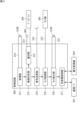
- FIG. 4 is a functional block diagram showing an example of the functions of the control circuit 360.
- the control circuit 360 has the following functions: an acquisition section 371 , a connection determination section 372 , a notification section 373 , a signal transmission section 374 , a lock control section 375 , a lock detection section 376 , and a charge/discharge control section 377 .
- the connection determination unit 372 determines whether the connector 300 is connected to the inlet 120 based on the detection result of the switch 310B.
- the switch 310B is in the OFF state when the connector 300 is in the disconnected state and in the connected state with respect to the inlet 120.
- Switch 310B is turned on when connector 300 is half-connected to inlet 120.
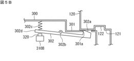
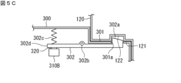
- 5A, 5B, and 5C are diagrams showing an example of the relationship between the position of the connector 300 with respect to the inlet 120 and the latch 302a.
- FIG. 5B shows a state in which the plug 301 of the connector 300 is being inserted into the socket 121 of the inlet 120, that is, a half-connected state.
- the latch 302a is pushed downward by the inner wall of the socket 121 of the inlet 120, and the position of the latch 302a changes to the lower position.
- the second end 302d of the latch member 302 moves upward against the force of the spring 302c.
- the half-connected state is a state in which the plug 301 is inserted into the socket 121 and the latch 302a is pressed against the side surface of the socket 121.
- FIG. 5C shows a state in which the plug 301 of the connector 300 has been completely inserted into the socket 121 of the inlet 120, that is, a connected state.
- An opening 122 for inserting the latch 302a is provided in the inner wall of the socket 121 of the inlet 120.
- the actuator 320 of the switch 310B is pushed by the second end 302d of the latch member 302 pushed downward by the spring 302c, and the switch 310B shifts to the OFF state.
- the connected state is a state in which the plug 301 is inserted into the socket 121 and the latch 302a is inserted into the opening 122 of the socket 121.
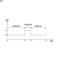
- FIG. 6 is a graph showing an example of the output signal from the switch 310B.
- the vertical axis represents the output voltage of switch 310B
- the horizontal axis represents time.
- the switch 310B does not output a voltage in the OFF state (that is, the output voltage is the reference voltage V0), and outputs a preset voltage in the ON state (that is, the output voltage is the voltage V1).
- the switch 310B outputs an ON signal that is a voltage signal with a voltage value V1.
- the connector 300 and the inlet 120 are in a disconnected state, and the switch 310B is in an OFF state.
- the output voltage of switch 310B during this period is V0.
- the plug 301 of the connector 300 begins to be inserted into the socket 121 of the inlet 120.
- the switch 310B transitions from the OFF state to the ON state, and the output voltage of the switch 310B changes from V0 to V1.
- t1 and t2 which is a period during which the plug 301 is inserted into the socket 121, the connector 300 and the inlet 120 are in a semi-connected state, and the switch 310B is in an ON state.
- the output voltage of switch 310B during this period is V1.
- connection determination unit 372 determines that the connector 300 is connected to the inlet 120 when the state of the switch 310B transitions from the OFF state to the ON state and then to the OFF state. This will be explained in detail below.
- the connection determination unit 372 detects time t1 when the output voltage of the switch 310B changes from V0 to V1, that is, the rising point of the output voltage of the switch 310B (see FIG. 6). The connection determination unit 372 determines that the connector 300 and the inlet 120 are not connected during the period from t0 to t1 when the output voltage of the switch 310B is V0.
- the connection determination unit 372 detects time t2 when the output voltage of the switch 310B changes from V1 to V0, that is, the falling point of the output voltage of the switch 310B (see FIG. 6). The connection determining unit 372 determines that the connector 300 and the inlet 120 are in a semi-connected state during the period from t1 to t2 when the output voltage of the switch 310B is V1. Furthermore, the connection determination unit 372 determines that the connector 300 and the inlet 120 are in a connected state during the period from t2 to t3 when the output voltage of the switch 310B is V0.
- the charging/discharging control unit 377 starts a charging/discharging operation for charging and discharging the battery 110.
- the charging/discharging control unit 377 can control the power converter 352 and can cause the power converter 352 to perform charging/discharging operation of the battery 110.
- the notification unit 373 When the connection determination unit 372 determines that the connector 300 is connected to the inlet 120, the notification unit 373 outputs notification information for notifying the user of the successful connection between the connector 300 and the inlet 120. Specifically, for example, the notification unit 373 outputs a control signal as notification information to the signal line 311, and lights up the LED 304. As a result, the user is notified of the successful connection between the connector 300 and the inlet 120. In another example, the notification unit 373 outputs a video signal as notification information to the display 354, and causes the display 354 to display information on the successful connection between the connector 300 and the inlet 120.
- the signal transmitting unit 374 transmits a charging/discharging start signal to the electric vehicle 100 when the connection determining unit 372 determines that the connector 300 is connected to the inlet 120.
- the charging/discharging start signal is a signal for notifying electric vehicle 100 that charging/discharging operation can be started.
- the on-vehicle control device 130 of the electric vehicle 100 receives the charging/discharging start signal, it starts communication with the charging/discharging device 200 and transmits battery information necessary for charging/discharging operation to the charging/discharging device 200.
- the battery information is characteristic information of the battery 110, and includes, for example, the maximum capacity, maximum output voltage, and SOC (State Of Charge) of the battery 110.
- the lock control unit 375 causes the lock unit 303 to lock the connection state of the connector 300 to the inlet 120. That is, the lock control section 375 transmits a control signal to the lock section 303 via the signal line 312. As a result, a current is applied to the solenoid, and the movable piece 303b is moved. The movable piece 303b restricts the rotation of the latch member 302, and the connection state of the connector 300 to the inlet 120 is locked.
- the lock detection unit 376 detects the locking state of the connector 300 connected to the inlet 120 by the lock unit 303 . That is, the lock detection section 376 detects the locked state by the lock section 303 by receiving the ON signal from the switch 310A.
- the charging/discharging control unit 377 starts the charging/discharging operation when the locked state of connection of the connector 300 to the inlet 120 is detected.
- the nonvolatile memory 362 or the volatile memory 363 is provided with a connection flag, which is an area for indicating the connection state of the connector 300 to the inlet 120.
- a connection flag is an area for indicating the connection state of the connector 300 to the inlet 120.
- the connection flag is OFF (0), it indicates a disconnection state between the connector 300 and the inlet 120, and when it is ON (1), it indicates a connection state between the connector 300 and the inlet 120.
- the initial state of the connection flag is OFF.
- the user When charging and discharging the battery 110 of the electric vehicle 100, the user connects the connector 300 of the charging/discharging device 200 to the inlet 120 of the electric vehicle 100.
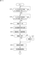
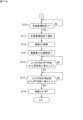
- the processor 361 monitors the output signal of the switch 310B and determines whether the switch 310B has changed from an OFF state to an ON state, that is, the positional relationship between the connector 300 and the inlet 120 has changed from an unconnected state to a semi-connected state. It is determined whether the transition has occurred (step S101). If the switch 310B has not changed from the OFF state to the ON state (NO in step S101), the processor 361 repeats step S101.
- connection flag is OFF and the switch 310B changes from the ON state to the OFF state (YES in step S102)
- the processor 361 determines that the positional relationship between the connector 300 and the inlet 120 has transitioned from the semi-connected state to the connected state. It can be determined that In this case, the processor 361 sets the connection flag to ON (step S103).
- the processor 361 transmits a charge/discharge start signal via the signal line 315 (step S104). This notifies the on-vehicle control device 130 that charging and discharging operation can be started.
- the processor 361 starts communication with the electric vehicle 100 (step S105). In communication between the charging/discharging device 200 and the electric vehicle 100, battery information and power information are exchanged.
- Step S108 Specifically, for example, a screen for notifying that the connection between connector 300 and inlet 120 has been successful is displayed on display 354. In other examples, LED 304 is illuminated to notify the user that the connection between connector 300 and inlet 120 has been successful.
- the charging/discharging device 200 includes, for example, a communication interface for short-range wireless communication or mobile communication, and the connector 300 and the inlet 120 can be connected to a mobile terminal such as a user's smartphone by wireless communication. A screen may be displayed to notify of success.
- charging of the battery 110 is completed when the amount of power output from the power converter 352 to the battery 110 reaches the required charge amount calculated from the SOC of the battery 110. For example, when the amount of power input from the battery 110 to the power converter 352 reaches the amount of discharge calculated from the SOC of the battery 110, the discharge of the battery 110 is completed.
- the processor 361 determines whether the charging/discharging operation has ended (step S110). If the charging/discharging operation has not ended (NO in step S110), the processor 361 executes step S110 again.
- the processor 361 notifies the user of the end of the charging/discharging operation (step S111). Specifically, for example, a screen for notifying that the charging/discharging operation has ended is displayed on the display 354. In another example, an LED different from the LED 304 may be provided on the connector 300, and the user may be notified of the end of the charging/discharging operation by lighting the LED. As yet another example, a screen for notifying the end of the charging/discharging operation may be displayed on a mobile terminal such as a user's smartphone.
- the processor 361 controls the lock unit 303 to unlock the connection state (step S112). After the lock unit 303 becomes unlocked, the processor 361 notifies the on-board control device 130 of the end of the charging/discharging operation through communication with the on-board control device 130, and ends the communication with the on-board control device 130 ( Step S113).
- the processor 361 monitors the output signal of the switch 310B and determines whether the switch 310B has changed from an OFF state to an ON state, that is, the positional relationship between the connector 300 and the inlet 120 has changed from a connected state to a semi-connected state. It is determined whether the process has been performed (step S114). If the switch 310B has not changed from the OFF state to the ON state (NO in step S114), the processor 361 repeats step S114.
- step S114 the processor 361 determines that the positional relationship between the connector 300 and the inlet 120 has transitioned from the connected state to the semi-connected state. It can be determined that Next, the processor 361 determines whether the switch 310B has changed from the ON state to the OFF state, that is, whether the positional relationship between the connector 300 and the inlet 120 has transitioned from a semi-connected state to an unconnected state (step S115). . If the switch 310B has not changed from the ON state to the OFF state (NO in step S115), the processor 361 repeats step S115.
- connection flag is ON and the switch 310B changes from the ON state to the OFF state (YES in step S115)
- the processor 361 changes the positional relationship between the connector 300 and the inlet 120 from a semi-connected state to a non-connected state. It can be determined that In this case, the processor 361 sets the connection flag to OFF (step S116). With this, the charging control process ends.
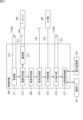
- FIG. 8 is a sequence diagram showing the operations of the charging/discharging device 200 and the electric vehicle 100 after the connector 300 is connected to the inlet 120.
- the on-vehicle control device 130 notifies the charge/discharge control device 350 of the battery information (step S207).
- the charging/discharging control device 350 notifies the on-vehicle control device 130 of the power information and starts charging/discharging operation (step S208).
- the user can set a scheduled charging/discharging period for the charging/discharging device 200. Specifically, for example, the user inputs the scheduled charging/discharging period to the charging/discharging device 200 using an input device (not shown) provided in the charging/discharging device 200 or using a mobile terminal such as a smartphone. Set.
- the time determining unit 380 acquires the current time and compares the acquired current time with the scheduled charging/discharging period. The time determination unit 380 determines whether the current time is included in the scheduled charging/discharging period. The charging/discharging control unit 377 starts charging/discharging operation when the time determining unit 380 determines that the current time is included in the scheduled charging/discharging period.
- FIG. 10 is a flowchart showing a modification of the charging/discharging control process by the charging/discharging control device according to the embodiment.
- the processor 361 detects the connection of the connector 300 to the inlet 120 by monitoring the output signal of the switch 310B and determining whether the switch 310B changes from the OFF state to the ON state and from the ON state to the OFF state. (Steps S101, S102). Upon detecting the connection of the connector 300 to the inlet 120, the processor 361 sets the connection flag to ON (step S103). Steps S101, S102, and S103 are the same as the processing described above, so detailed explanation will be omitted.
- the processor 361 determines whether the current time is included in the scheduled charging/discharging period (step S120). If the current time is not included in the scheduled charging/discharging period (NO in step S120), the processor 361 executes step S120 again. As a result, step S120 is repeated until the scheduled charging/discharging period arrives.
- Charging and discharging system 100 Electric vehicle 110 Battery 120 Inlet 121 Socket 122 Opening 130 On-vehicle control device 200 Charging and discharging device 300 Connector 301 Plug 301a Hole 302 Latch member 302a Latch 302b Fulcrum 302c Spring 302d Second end 303 Lock part 303a release button 303b Movable piece 304 LED 310A Switch 310B Switch 311, 312, 313, 314, 315 Signal line 316 Communication line 317 Power line 320 Actuator 330 Cable 350 Charge/discharge control device 351 Control circuit 352 Power converter 353 Battery 354 Display 360 Control circuit 361 Processor 362 Non-volatile Memory 363 Volatile memory 365 Charge/discharge control program 371 Acquisition unit 372 Connection determination unit 373 Notification unit 374 Signal transmission unit 375 Lock control unit 376 Lock detection unit 377 Charge/discharge control unit 380 Time determination unit 400 Commercial AC power supply 410 Load
Landscapes
- Engineering & Computer Science (AREA)
- Power Engineering (AREA)
- Transportation (AREA)
- Mechanical Engineering (AREA)
- Electric Propulsion And Braking For Vehicles (AREA)
- Charge And Discharge Circuits For Batteries Or The Like (AREA)
Priority Applications (3)
| Application Number | Priority Date | Filing Date | Title |
|---|---|---|---|
| JP2023546346A JPWO2023248386A1 (cg-RX-API-DMAC7.html) | 2022-06-22 | 2022-06-22 | |
| PCT/JP2022/024930 WO2023248386A1 (ja) | 2022-06-22 | 2022-06-22 | 充電システム、充電装置、及び充電制御方法 |
| JP2025004696A JP7907709B2 (ja) | 2025-01-14 | 充電システム、充電装置、及び充電制御方法 |
Applications Claiming Priority (1)
| Application Number | Priority Date | Filing Date | Title |
|---|---|---|---|
| PCT/JP2022/024930 WO2023248386A1 (ja) | 2022-06-22 | 2022-06-22 | 充電システム、充電装置、及び充電制御方法 |
Publications (1)
| Publication Number | Publication Date |
|---|---|
| WO2023248386A1 true WO2023248386A1 (ja) | 2023-12-28 |
Family
ID=89379598
Family Applications (1)
| Application Number | Title | Priority Date | Filing Date |
|---|---|---|---|
| PCT/JP2022/024930 Ceased WO2023248386A1 (ja) | 2022-06-22 | 2022-06-22 | 充電システム、充電装置、及び充電制御方法 |
Country Status (2)
| Country | Link |
|---|---|
| JP (1) | JPWO2023248386A1 (cg-RX-API-DMAC7.html) |
| WO (1) | WO2023248386A1 (cg-RX-API-DMAC7.html) |
Citations (7)
| Publication number | Priority date | Publication date | Assignee | Title |
|---|---|---|---|---|
| JP2014207121A (ja) * | 2013-04-12 | 2014-10-30 | パナソニック株式会社 | 電気接続用コネクタ |
| JP2014239617A (ja) * | 2013-06-10 | 2014-12-18 | 日産自動車株式会社 | 車両用外部充電器接続構造 |
| JP2018042300A (ja) * | 2016-09-05 | 2018-03-15 | トヨタ自動車株式会社 | 充電装置及び充電装置の制御方法 |
| JP2021065012A (ja) * | 2019-10-11 | 2021-04-22 | トヨタ自動車株式会社 | 車両 |
| JP2021075213A (ja) * | 2019-11-12 | 2021-05-20 | トヨタ自動車株式会社 | 電動車 |
| JP2021125940A (ja) * | 2020-02-04 | 2021-08-30 | トヨタ自動車株式会社 | 車両制御装置 |
| JP2021136831A (ja) * | 2020-02-28 | 2021-09-13 | トヨタ自動車株式会社 | 車両および充電システム |
Family Cites Families (2)
| Publication number | Priority date | Publication date | Assignee | Title |
|---|---|---|---|---|
| JP5298165B2 (ja) * | 2011-07-07 | 2013-09-25 | 住電朝日精工株式会社 | 充電コネクタ |
| JP6985588B2 (ja) * | 2017-04-07 | 2021-12-22 | 富士通株式会社 | 電子装置及び電磁波吸収体 |
-
2022
- 2022-06-22 JP JP2023546346A patent/JPWO2023248386A1/ja active Pending
- 2022-06-22 WO PCT/JP2022/024930 patent/WO2023248386A1/ja not_active Ceased
Patent Citations (7)
| Publication number | Priority date | Publication date | Assignee | Title |
|---|---|---|---|---|
| JP2014207121A (ja) * | 2013-04-12 | 2014-10-30 | パナソニック株式会社 | 電気接続用コネクタ |
| JP2014239617A (ja) * | 2013-06-10 | 2014-12-18 | 日産自動車株式会社 | 車両用外部充電器接続構造 |
| JP2018042300A (ja) * | 2016-09-05 | 2018-03-15 | トヨタ自動車株式会社 | 充電装置及び充電装置の制御方法 |
| JP2021065012A (ja) * | 2019-10-11 | 2021-04-22 | トヨタ自動車株式会社 | 車両 |
| JP2021075213A (ja) * | 2019-11-12 | 2021-05-20 | トヨタ自動車株式会社 | 電動車 |
| JP2021125940A (ja) * | 2020-02-04 | 2021-08-30 | トヨタ自動車株式会社 | 車両制御装置 |
| JP2021136831A (ja) * | 2020-02-28 | 2021-09-13 | トヨタ自動車株式会社 | 車両および充電システム |
Also Published As
| Publication number | Publication date |
|---|---|
| JPWO2023248386A1 (cg-RX-API-DMAC7.html) | 2023-12-28 |
| JP2025063908A (ja) | 2025-04-16 |
Similar Documents
| Publication | Publication Date | Title |
|---|---|---|
| JP5840615B2 (ja) | ハイブリッド車両および電気車両のための電気接続装置、ならびにハイブリッド車両および電気車両のための充電方法 | |
| CN112644302B (zh) | 车辆 | |
| CN105083041B (zh) | 电气充电接口的锁止装置的控制 | |
| CN102781715B (zh) | 给机动车电池充电的方法以及机动车 | |
| JP5999006B2 (ja) | 充電プラグのロック装置 | |
| CN111516519B (zh) | 配备有蓄电装置的车辆 | |
| EP3024687B1 (en) | Vehicle with external charging | |
| KR101736998B1 (ko) | 전기 자동차용 충전 컨넥터 도난 방지 방법 및 장치 | |
| JP2012019636A (ja) | 車両用充電装置 | |
| JP5475542B2 (ja) | バッテリ充電用受電コネクタの給電プラグロック構造 | |
| CN114407714B (zh) | 车辆充电控制方法、装置、设备、介质及程序产品 | |
| JP2011165609A (ja) | 給電プラグのロック構造 | |
| CN107666078A (zh) | 充电枪锁定系统、车身组件和充电枪 | |
| CN107791860A (zh) | 充电装置及充电装置的控制方法 | |
| JP2019115163A (ja) | 車両の充電システム | |
| CN108604804A (zh) | 协议转换装置 | |
| JP2011083156A (ja) | 充電器および車両用充電制御システム | |
| CN112895929A (zh) | 车辆以及锁定控制系统 | |
| JP7404884B2 (ja) | 充放電装置、係止状態検出方法及びコンピュータプログラム | |
| JP5437908B2 (ja) | プラグロック構造 | |
| CN109263503B (zh) | 带车车互联功能的充电桩 | |
| JP2011243343A (ja) | プラグロック構造 | |
| CN109927570B (zh) | 充电控制方法、装置、充电插座和充电设备 | |
| JP2010124556A (ja) | 給電装置および車両 | |
| JP2025063908A (ja) | 充電システム、充電装置、及び充電制御方法 |
Legal Events
| Date | Code | Title | Description |
|---|---|---|---|
| ENP | Entry into the national phase |
Ref document number: 2023546346 Country of ref document: JP Kind code of ref document: A |
|
| 121 | Ep: the epo has been informed by wipo that ep was designated in this application |
Ref document number: 22947947 Country of ref document: EP Kind code of ref document: A1 |
|
| NENP | Non-entry into the national phase |
Ref country code: DE |
|
| 122 | Ep: pct application non-entry in european phase |
Ref document number: 22947947 Country of ref document: EP Kind code of ref document: A1 |