WO2023238849A1 - 煙検知装置 - Google Patents
煙検知装置 Download PDFInfo
- Publication number
- WO2023238849A1 WO2023238849A1 PCT/JP2023/020955 JP2023020955W WO2023238849A1 WO 2023238849 A1 WO2023238849 A1 WO 2023238849A1 JP 2023020955 W JP2023020955 W JP 2023020955W WO 2023238849 A1 WO2023238849 A1 WO 2023238849A1
- Authority
- WO
- WIPO (PCT)
- Prior art keywords
- light
- light receiving
- smoke
- section
- unit
- Prior art date
- Legal status (The legal status is an assumption and is not a legal conclusion. Google has not performed a legal analysis and makes no representation as to the accuracy of the status listed.)
- Ceased
Links
Images


Classifications
-
- G—PHYSICS
- G01—MEASURING; TESTING
- G01N—INVESTIGATING OR ANALYSING MATERIALS BY DETERMINING THEIR CHEMICAL OR PHYSICAL PROPERTIES
- G01N21/00—Investigating or analysing materials by the use of optical means, i.e. using sub-millimetre waves, infrared, visible or ultraviolet light
- G01N21/17—Systems in which incident light is modified in accordance with the properties of the material investigated
- G01N21/21—Polarisation-affecting properties
-
- G—PHYSICS
- G01—MEASURING; TESTING
- G01N—INVESTIGATING OR ANALYSING MATERIALS BY DETERMINING THEIR CHEMICAL OR PHYSICAL PROPERTIES
- G01N21/00—Investigating or analysing materials by the use of optical means, i.e. using sub-millimetre waves, infrared, visible or ultraviolet light
- G01N21/17—Systems in which incident light is modified in accordance with the properties of the material investigated
- G01N21/47—Scattering, i.e. diffuse reflection
- G01N21/49—Scattering, i.e. diffuse reflection within a body or fluid
- G01N21/53—Scattering, i.e. diffuse reflection within a body or fluid within a flowing fluid, e.g. smoke
-
- G—PHYSICS
- G08—SIGNALLING
- G08B—SIGNALLING SYSTEMS, e.g. PERSONAL CALLING SYSTEMS; ORDER TELEGRAPHS; ALARM SYSTEMS
- G08B17/00—Fire alarms; Alarms responsive to explosion
- G08B17/10—Actuation by presence of smoke or gases, e.g. automatic alarm devices for analysing flowing fluid materials by the use of optical means
- G08B17/103—Actuation by presence of smoke or gases, e.g. automatic alarm devices for analysing flowing fluid materials by the use of optical means using a light emitting and receiving device
- G08B17/107—Actuation by presence of smoke or gases, e.g. automatic alarm devices for analysing flowing fluid materials by the use of optical means using a light emitting and receiving device for detecting light-scattering due to smoke
Definitions
- the present invention relates to a device for detecting smoke.
- a smoke detection device that detects the occurrence of smoke in a monitored space by detecting smoke contained in the monitored space.
- One type of smoke detection device is a type called a photoelectric type.
- a photoelectric smoke detection device generates smoke particles when the light emitting part is reflected by smoke particles in the air flowing from the outside into a container that houses the light emitting part and the light receiving part. Smoke detection is performed based on the signal.
- a dual-receiver type smoke detection device emits polarized light from a light emitting part in the direction of the light emitting axis, and detects smoke in the air based on signals generated by two light receiving parts that have light receiving axes that intersect with the light emitting axis from different directions. Determine the type.
- Patent Document 1 An example of a patent document disclosing a two-light receiving type smoke detection device is Patent Document 1.
- a photoelectric smoke detection device usually calculates a multiplier by dividing the standard amplitude value by the amplitude value of the signal generated by the light receiving part under the standard environment, and then calculates the multiplier for the signal generated by the light receiving part during operation.
- the output value of the light receiving section under the reference environment in any product indicates the reference intensity.
- the output value of the light receiving section generally changes gradually due to age-related deterioration of the light receiving element, deposition of dirt on the light emitting section and the light receiving section, etc.
- the two-light receiving type smoke detection device determines the type of smoke in the air based on the signals generated by each of the two light receiving sections. Therefore, if the output values of these two light receiving sections change due to aging or the like, the smoke detection device may not be able to correctly determine the type of smoke.
- an object of the present invention is to provide a dual-light receiving type smoke detection device that can accurately determine the type of smoke even if it deteriorates over time.
- the present invention includes a light emitting section that emits polarized light, a first light receiving section that has a first light receiving axis that intersects with the light emitting axis of the light emitting section, and a first light receiving section that has a first light receiving axis that intersects with the light emitting axis of the light emitting section.
- a second light receiving section having a second light receiving axis in a direction different from the first light receiving axis, and detecting smoke in the air based on a signal generated by the first light receiving section while the light emitting section is emitting light;
- the type of smoke in the air is determined based on a signal generated by the first light receiving unit while the light emitting unit is emitting light, and a signal generated by the second light receiving unit while the light emitting unit is emitting light.
- a determination unit and a determination unit that determines the amplitude value of the signal generated by the first light receiving unit while the light emission unit is emitting light, while the smoke determination unit is not detecting smoke in the air.
- a multiplication factor is set by which at least one of the signal generated by the first light receiving section and the signal generated by the second light receiving section is multiplied so that the ratio of the amplitude values of the signals generated by the second light receiving section becomes a predetermined value.
- a multiplication factor determining section that determines the amplitude value of at least one of the signal generated by the first light receiving section and the signal generated by the second light receiving section, and the smoke determining section determines the amplitude value determined by the multiplication factor determining section.
- the type of smoke can be correctly determined even if deterioration occurs over time.
- FIG. 1 is a diagram schematically showing the configuration of a smoke detection device according to an embodiment.
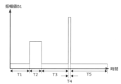
- 7 is a graph showing a change over time in the amplitude value of a signal obtained by amplifying a signal generated by the first light receiving section of the smoke detection device according to an embodiment by a signal amplification section.
- FIG. 1 is a diagram schematically showing the configuration of a smoke detection device 1. As shown in FIG. However, in FIG. 1, illustration of components not related to the features of the present invention is omitted.
- FIG. 1(A) is a plan view of the smoke detection device 1 with the lid of the container removed.
- FIG. 1(B) is a view of the cross section indicated by the broken line in FIG. 1(A) as viewed in the direction of arrow A.
- the smoke detection device 1 includes a first electronic circuit board 10, a second electronic circuit board 11, a third electronic circuit board 12, a first light emitting section 13, a first light receiving section 14, a second light receiving section 15, a light shielding member 16, and a third electronic circuit board 12. 2, a light emitting section 17, a signal amplifying section 18, a signal processing section 19, and a container 20.
- the first electronic circuit board 10 is an electronic circuit board arranged to stand up perpendicularly to a horizontal surface.
- a first light emitting section 13 is arranged on the first electronic circuit board 10 .
- the second electronic circuit board 11 is an electronic circuit board arranged in a direction along a horizontal plane.
- a first light receiving section 14 , a light shielding member 16 , a second light emitting section 17 , a signal amplifying section 18 , and a signal processing section 19 are arranged on the second electronic circuit board 11 .
- the third electronic circuit board 12 is an electronic circuit board that is arranged to stand up perpendicularly to a horizontal plane.
- a second light receiving section 15 is arranged on the third electronic circuit board 12 .
- the signal amplifying section 18 and the signal processing section 19 may be arranged on an electronic circuit board other than the second electronic circuit board 11 (for example, the first electronic circuit board 10 or the third electronic circuit board 12).
- the first light emitting unit 13 emits polarized light in the direction of a light emitting axis (hereinafter referred to as "light emitting axis B") indicated by arrow B in FIG.
- light emitting axis B a light emitting axis
- the direction of the straight line is perpendicular to the horizontal plane
- the polarized light emitted by the first light emitting section 13 is elliptically polarized light
- the direction of is perpendicular to the horizontal plane.
- the first light receiving unit 14 receives light directed in the direction of a first light receiving axis (hereinafter referred to as "first light receiving axis C") indicated by arrow C in FIG. 1(B), and indicates the intensity of the received light. Generate a signal.
- first light receiving axis C the amplitude value of the signal generated by the first light receiving section 14 will be referred to as amplitude value A1.
- the first light-receiving axis C is an axis that intersects the light-emitting axis B at a predetermined angle within a vertical plane (a plane perpendicular to the horizontal plane) that includes the light-emitting axis B.
- the second light receiving unit 15 receives light directed in the direction of a second light receiving axis (hereinafter referred to as "second light receiving axis D") indicated by arrow D in FIG. 1(A), and indicates the intensity of the received light. Generate a signal.
- the amplitude value of the signal generated by the second light receiving section 15 will be referred to as amplitude value A2.
- the second light-receiving axis D is an axis that intersects the light-emitting axis B at a predetermined angle within a horizontal plane that includes the light-emitting axis B.
- angle between the light emitting axis B and the first light receiving axis C and the angle between the light emitting axis B and the second light receiving axis D may be the same or different.
- the light shielding member 16 is a cylindrical light shielding member arranged to surround the first light receiving section 14.
- the upper bottom surface of the light shielding member 16 is open so that light directed toward the first light receiving axis C reaches the first light receiving portion 14 .
- the light blocking member 16 blocks light directed toward the first light receiving section 14 in a direction intersecting the first light receiving axis C.
- the light that is blocked by the light shielding member 16 includes light that is emitted from the first light emitting section 13 and deviates from the light emitting axis B and heads towards the first light receiving section 14, and light that is emitted from the first light emitting section 13 and reflected within the container 20.
- the light that travels toward the first light receiving section 14 is included.
- the light blocking member 16 serves to reduce the influence of such light on the determination of the presence or absence of smoke and the determination of the type of smoke.
- the second light emitting section 17 is a non-contact device for determining the degree of contamination of at least one of the container 20 and the structures inside the container 20 (including the first light emitting section 13, the first light receiving section 14, and the second light receiving section 15). Emit polarized light. The light emitted by the second light emitting section 17 is directed toward a wide area within the container 20 including the smoke detection area.
- the second light emitting section 17 is arranged at a position where the light directly directed from the second light emitting section 17 to the first light receiving section 14 is blocked by the light blocking member 16. Therefore, compared to the case where the light emitted by the second light emitting section 17 directly reaches the first light receiving section 14, the amplitude value A1 of the signal generated by the first light receiving section 14 at the time of soiling determination becomes smaller overall. The amount of change in the amplitude value A1 at the time of staining with respect to the amplitude value A1 at the normal time is noticeable. Therefore, the degree of contamination can be easily determined.
- the signal amplifying section 18 is an amplifier that amplifies the signals generated by the first light receiving section 14 and the second light receiving section 15. In this embodiment, the signal amplifying section 18 amplifies the signal generated by the first light receiving section 14 and the signal generated by the second light receiving section 15 with the same amplification factor G.
- amplitude value B1 is a value obtained by multiplying the amplitude value A1 by the amplification factor G.
- amplitude value B2 is a value obtained by multiplying the amplitude value A2 by the amplification factor G.
- the signal processing section 19 is a unit that performs data processing, and includes an A/D converter that converts the analog signals generated by the first light receiving section 14 and the second light receiving section 15 and amplified by the signal amplification section 18 into digital signals, and an A/D converter that converts the data. It has a memory (storage unit) for storing data, a processor for processing data, a clock for measuring time, etc.
- initial values of the multiplication factor M1 for the first light receiving section 14 and the multiplication factor M2 for the second light receiving section 15 are stored in the memory. Then, while the smoke detection device 1 is in operation, the multiplication factor M1 and the multiplication factor M2 are updated by a multiplication factor determining section, which will be described later.
- the initial value of the multiplication factor M1 is the value generated by the first light receiving section 14 in an environment where the inside of the container 20 is filled with white smoke (or a substitute for white smoke) at a predetermined concentration and the first light emitting section 13 is emitting light.
- This is the value obtained by dividing the predetermined reference value S by the amplitude value B1 of the signal obtained by amplifying the signal by the signal amplifying section 18. That is, the multiplication factor M1 is set in the smoke detection device 1 as an initial value so that the reference value S is a value obtained by multiplying the amplitude value B1 by the multiplication factor M1 under the above environment.
- the initial value of the multiplication factor M2 is the signal obtained by amplifying the signal generated by the second light receiving section 15 by the signal amplifying section 18 in an environment where the inside of the container 20 is filled with white smoke and the first light emitting section 13 is emitting light. This is the value obtained by dividing the reference value S by the amplitude value B2. That is, the multiplication factor M2 is set in the smoke detection device 1 as an initial value so that the reference value S is a value obtained by multiplying the amplitude value B2 by the multiplication factor M2 under the above environment.
- the amplitude value obtained by multiplying the amplitude value B1 of the signal generated by the first light receiving section 14 by the multiplication factor M1 will be referred to as the amplitude value C1 of the first light receiving section 14.
- the value obtained by multiplying the amplitude value B2 of the signal generated by the second light receiving section 15 by the signal amplifying section 18 by the multiplication factor M2 is referred to as the amplitude value C2 of the second light receiving section 15.
- the reference value S used to calculate the initial value of the multiplication factor M1 and the reference value S used to calculate the initial value of the multiplication factor M2 are the same value. Therefore, the ratio of the amplitude value B2 to the amplitude value B1 (or the amplitude value C2 to the amplitude value C1) in an environment where the inside of the container 20 is filled with white smoke and the first light emitting section 13 is emitting light is 1. Note that the reference value S used to calculate the initial value of the multiplication factor M1 and the reference value S used to calculate the initial value of the multiplication factor M2 may be different values.
- the signal processing unit 19 functions as a device including a light emission control unit, a smoke determination unit, a contamination determination unit, a multiplication factor determination unit, and an abnormality detection unit by a processor performing data processing according to a program stored in the memory.
- the light emission control section instructs the first light emitting section 13 and the second light emitting section 17 to start and end light emission.
- the smoke detection device 1 operates in the smoke determination mode from 0:00 to 23:59 every day, and operates in the contamination determination mode from 23:59 to 24:00 (0:00 the next day). shall be taken as a thing.
- the smoke determination mode is an operation mode in which smoke is detected and the type of detected smoke is determined.
- the light emission control section instructs the first light emitting section 13 to start emitting light, and instructs the second light emitting section 17 to end light emission.
- the contamination determination mode is a mode for determining the degree of contamination of at least one of the container 20 and the structure within the container 20.
- the light emission control section instructs the first light emitting section 13 to end light emission and instructs the second light emitting section 17 to start light emission.
- the lengths of the smoke determination mode and the contamination determination mode are not limited to those described above.
- the smoke determination section detects smoke in the air based on the signal generated by the first light receiving section 14 in the smoke determination mode.
- a threshold value U1 for smoke detection is stored in the memory.
- the smoke determination section calculates a predetermined comparison result between an amplitude value C1 obtained by multiplying an amplitude value B1 of a signal generated by the first light receiving section 14 by a multiplier M1 and a threshold value U1. If the condition E1 is satisfied, it is determined that smoke is generated in the space around the smoke detection device 1.
- Condition E1 is, for example, a condition in which, in a comparison between amplitude value C1 and threshold value U1 that is repeatedly performed at a predetermined time interval, a determination result that the amplitude value C1 exceeds the threshold value U1 occurs a predetermined number of times in succession. It is not limited to this.
- the smoke determination unit detects smoke in the air in the space around the smoke detection device 1 by the above-described determination
- the smoke determination unit detects the signal generated by the first light receiving unit 14 while the first light emitting unit 13 is emitting light
- the first The type of smoke in the air in the space around the smoke detection device 1 is determined based on the signal generated by the second light receiving section 15 while the light emitting section 13 is emitting light.
- the memory stores, for example, a threshold value U2 for distinguishing between white smoke and gray smoke, and a threshold value U3 for discriminating between gray smoke and black smoke. ing.
- white smoke, gray smoke, and black smoke are examples of the types of smoke that are determined by the smoke determining section, and other types of smoke may be distinguishable.
- the number of threshold values used by the smoke determining section to determine the types of smoke may vary depending on the number of types of smoke that can be determined by the smoke determining section and the method for determining the smoke types.
- the smoke determination section determines a second value for the amplitude value C1 obtained by multiplying the amplitude value B1 of the signal generated by the first light receiving section 14 by the multiplication factor M1.
- the ratio R of the amplitude value C2 is calculated by multiplying the amplitude value B2 of the signal generated by the light receiving unit 15 by the signal amplification unit 18 by the multiplication factor M2.
- the smoke determination unit determines that if the ratio R is less than or equal to the threshold U2, the type of smoke is white smoke, if the ratio R is greater than the threshold U2 and less than or equal to the threshold U3, the type of smoke is gray smoke, and if the ratio R is less than the threshold U3, the smoke type is determined to be gray smoke. If it is large, the type of smoke is determined to be black smoke.
- the smoke detection device 1 When the smoke detection unit detects smoke, the smoke detection device 1 includes a display (liquid crystal display or 7 segment Display a warning message on an LED (not shown in Figure 1), turn on a warning light (not shown in Figure 1), detect smoke and the type of smoke from the communication unit (not shown in Figure 1) to the upper system. Perform predetermined processing such as sending a notification indicating the smoke.
- a display liquid crystal display or 7 segment Display a warning message on an LED (not shown in Figure 1), turn on a warning light (not shown in Figure 1), detect smoke and the type of smoke from the communication unit (not shown in Figure 1) to the upper system. Perform predetermined processing such as sending a notification indicating the
- the contamination determination section determines whether at least one of the container 20 and the structure within the container 20 is soiled based on at least one of the signal generated by the first light receiving section 14 and the signal generated by the second light receiving section 15. Determine the degree.
- the memory stores a threshold U4 and a threshold U5 for stain determination.
- the stain determination unit determines that, for example, an amplitude value C1 obtained by multiplying an amplitude value B1 of a signal generated by the first light receiving unit 14 by a multiplier M1 of a signal generated by the signal amplification unit 18 is less than a threshold value U4.
- the smoke detection device 1 When the contamination determination unit determines that the degree of contamination exceeds the allowable range, the smoke detection device 1 outputs a warning message such as "Cleaning is required" from a speaker (not shown in FIG. 1), and also transmits a communication message. The unit (not shown in FIG. 1) sends a notification urging the host system to clean the smoke detection device 1.
- the multiplication factor determining section is configured to reduce the influence of aging deterioration, dirt, etc. of the first light emitting section 13, first light receiving section 14, and second light receiving section 15 on the determination result by the smoke determining section. It plays a role of updating the multiplication factor M1 and the multiplication factor M2 during the operation of the system.
- the multiplication factor determining section determines whether the second light receiving section 15 generates a signal corresponding to the amplitude value of the signal generated by the first light receiving section 14 in the smoke determination mode during a period when smoke in the air is not detected by the smoke determining section.
- a multiplication factor by which at least one of the signal generated by the first light receiving section 14 and the signal generated by the second light receiving section 15 is multiplied is determined so that the ratio of the amplitude values of the signals becomes a predetermined value.
- the multiplication factor determining unit determines updated values for both the multiplication factor M1 and the multiplication factor M2.
- a specific example is shown below.
- the amplitude value ⁇ 1 and the amplitude value ⁇ 2 are stored in the memory when the smoke detection device 1 is shipped from the factory.
- the amplitude value ⁇ 1 is determined by multiplying the amplitude value B1 of the signal generated by the first light receiving unit 14 by the signal amplifying unit 18 by a factor M1 in the smoke determination mode in a smokeless environment when the smoke detection device 1 is shipped from the factory. This is the value multiplied by the initial value of .
- the amplitude value ⁇ 2 is determined by multiplying the amplitude value B2 of the signal generated by the second light receiving unit 15 by the signal amplification unit 18 in the smoke determination mode in a smokeless environment at the time of factory shipment of the smoke detection device 1 by a factor M2. This is the value multiplied by the initial value of .
- the memory stores the amplitude value B1 and the amplitude value B2 that are continuously measured during operation of the smoke detection device 1, for example.
- a period of a predetermined length of time (hereinafter referred to as 10 minutes) in the most recent past is sequentially stored as log data.
- the multiplication factor determining unit first identifies a period in the recent past in which no smoke was detected.
- FIG. 2 is a graph showing changes over time in the amplitude value B1 during a predetermined period of time in the recent past, which is shown by log data stored in the memory.
- the period T4 is the period of the stain determination mode
- the other periods are the periods of the smoke determination mode.
- the multiplication factor determination unit determines that the value obtained by multiplying the amplitude value B1 in the period T2 by the multiplication factor M1 at that time, which is indicated by the log data read from the memory, continuously exceeds the threshold value U1. It is determined that As a result, the multiplication factor determination unit specifies period T2 as a period in which smoke is detected, and specifies other periods, that is, periods T1, T3, T4, and T5, as periods in which smoke is not detected. .
- the multiplication factor determining unit determines the amplitude value B1 in the periods T1, T3, and T5 excluding the period T4, which is the period in the stain determination mode, among the periods T1, T3, T4, and T5, which are the periods in which smoke is not detected.
- the representative value for example, the average value D1 of the amplitude values B1 during those periods is calculated. Note that instead of the average value, a median value, mode value, etc. may be used as the representative value.
- the multiplication factor determination unit divides the amplitude value ⁇ 1 by the average value D1 to calculate the updated multiplication factor M1.
- the updated multiplication factor M1 calculated in this way is based on the fact that in the current smoke detection device 1, the amplitude value C1 calculated in a smokeless environment in the smoke detection mode is the same as that in the smoke detection device 1 at the time of factory shipment. This is a multiplication factor adjusted to match the amplitude value ⁇ 1 calculated in a smokeless environment during mode.
- the multiplication factor determining unit overwrites the multiplication factor M1 stored in the memory with the updated multiplication factor M1 calculated in this way.
- the multiplication factor determining unit calculates, for example, the average value D2 of the amplitude values B2 in the periods T1, T3, and T5 as the representative value of the amplitude values B2 in those periods.
- the multiplication factor determination unit divides the amplitude value ⁇ 2 by the average value D2 to calculate the updated multiplication factor M2.
- the updated multiplication factor M2 calculated in this way is based on the fact that in the current smoke detection device 1, the amplitude value C2 calculated in a smokeless environment in the smoke detection mode is different from that in the smoke detection device 1 at the time of factory shipment. This is a multiplication factor adjusted to match the amplitude value ⁇ 2 calculated in a smokeless environment during mode.
- the multiplication factor determining unit overwrites the multiplication factor M2 stored in the memory with the updated multiplication factor M2 calculated in this manner.
- the ratio of the amplitude value C1 and the amplitude value C2 calculated using the updated multiplication factor M1 and the multiplication factor M2 determined by the multiplication factor determination unit as described above matches the ratio of the amplitude value ⁇ 1 and the amplitude value ⁇ 2. . That is, the multiplication factor determining unit updates the updated multiplication factor M1 and multiplication factor M2 so that the ratio of the amplitude value C2 to the amplitude value C1 becomes the ratio of the amplitude value ⁇ 2 to the amplitude value ⁇ 1 given as the initial value. Determine.
- the multiplication factor M1 and the multiplication factor M2 are updated by the multiplication factor determining section as described above, the influence of aging deterioration, staining, etc. of the smoke detection device 1 on the determination result of the smoke determination section is reduced.
- the abnormality detection section detects the amplitude of the signal generated by the second light receiving section 15 relative to the amplitude value of the signal generated by the first light receiving section 14 in the smoke judgment mode during a period when smoke in the air is not detected by the smoke judgment section. An abnormality in the smoke detection device 1 is detected based on the ratio of values.
- the abnormality detection unit reads the log data from the memory every time a predetermined length of time (for example, 5 minutes) elapses, and measures the data at the same timing indicated by the log data.
- the ratio P of the amplitude value B2 to the amplitude value B1 is calculated.
- FIG. 3 is an example of a graph showing changes over time in the ratio P calculated by the abnormality detection unit for a predetermined period in the past.
- period T4 is the period of the contamination determination mode
- period T2 is the period during which smoke is detected. Note that the abnormality detection section identifies the period during which smoke is detected using the same method as the multiplication factor determination section.
- the abnormality detection unit detects that the ratio P changes discontinuously at time t1 during periods T1, T3, and T5, which are periods in which smoke is not detected in the smoke determination mode. For example, the abnormality detection unit identifies the time when the ratio P is changing discontinuously based on the determination result of whether the rate of change of the moving average of the ratio P exceeds a predetermined threshold.
- the time at which the ratio P is changing discontinuously may be identified by the method described above.
- the abnormality detection unit determines that some abnormality has occurred in the smoke detection device 1 at time t1.
- the smoke detection device 1 When the smoke detection device 1 detects an abnormality in its own device using the abnormality detection unit, it outputs a warning message such as “An abnormality has occurred” from the speaker (not shown in FIG. 1), and also outputs a warning message from the communication unit ( 1 (not shown) sends a notification indicating the occurrence of an abnormality to the higher-level system.
- a warning message such as “An abnormality has occurred” from the speaker (not shown in FIG. 1)
- a warning message from the communication unit ( 1 (not shown) sends a notification indicating the occurrence of an abnormality to the higher-level system.
- the abnormality detection unit detecting an abnormality in the smoke detection device 1 based on the ratio P of the amplitude value B2 to the amplitude value B1 as described above, for example, an abnormality in the smoke detection device 1 is detected based only on the amplitude value B1. It is possible to detect the occurrence of an abnormality that is difficult to detect when detecting an abnormality in the smoke detection device 1 based only on the amplitude value B2. For example, when dust is generated around the smoke detection device 1 and fine dust enters the container 20, the amplitude value B1 and the amplitude value B2 change in conjunction with each other. Therefore, compared to the amplitude value B1 or the amplitude value B2, the ratio P is less likely to be influenced by these disturbances. Therefore, by performing abnormality detection based on the ratio P, abnormalities that are not caused by these disturbances can be easily detected.
- the container 20 (see FIG. 1) is a component that forms a dark space for detecting smoke, and houses the first light emitting section 13, the first light receiving section 14, the second light receiving section 15, etc.
- the container 20 is provided with an inlet that serves as a passage for air to flow into the interior from the space to be monitored, and an outlet that serves as a passage for air that has flowed into the interior to flow out to the outside.
- a filter or the like may be provided to remove dust particles having a size larger than that of the particles.
- the type of smoke can be correctly determined even if deterioration occurs over time.
- the multiplication factor determination unit determines that the first light-receiving unit 14 and the second light-receiving unit 15 generate light in a smoke-free environment in the smoke determination mode, that is, in a state where the first light-emitting unit 13 is emitting light. Based on the signal, the updated multiplication factor M1 and multiplication factor M2 are determined.
- the signals generated by the first light receiving section 14 and the second light receiving section 15 are stray light that is light emitted by the first light emitting section 13 and reflected on the inner wall surface of the container 20 or structures inside the container 20. It is a signal generated in response to. Therefore, the amplitude values of the signals generated by the first light receiving section 14 and the second light receiving section 15 may be too small.
- the multiplication factor determining section is configured based on the signals generated by the first light receiving section 14 and the second light receiving section 15 in the contamination judgment mode instead of the smoke judgment mode, that is, in the state where the second light emitting section 17 is emitting light.
- a configuration may be adopted in which the updated multiplication factor M1 and multiplication factor M2 are determined.
- an amplitude value ⁇ 1 and an amplitude value ⁇ 2 different from those in the above-described embodiment are stored in the memory at the time of factory shipment.
- the amplitude value ⁇ 1 and the amplitude value ⁇ 2 are values based on the signal generated by the first light receiving unit 14 or the second light receiving unit 15 in the smoke determination mode, whereas in this modification, the amplitude value ⁇ 1 ⁇ 1 and amplitude value ⁇ 2 are values based on signals generated by the first light receiving section 14 or the second light receiving section 15 in the stain determination mode.
- the amplitude value ⁇ 1 is the value of the signal generated by the first light receiving unit 14 in a smokeless environment in the contamination determination mode when the smoke detection device 1 is shipped from the factory. This is the value obtained by multiplying the amplitude value B1 by the initial value of the multiplication factor M1.
- the amplitude value ⁇ 2 is the signal obtained by amplifying the signal generated by the second light receiving unit 15 by the signal amplification unit 18 in a smokeless environment in the contamination determination mode when the smoke detection device 1 is shipped from the factory. This is the value obtained by multiplying the amplitude value B2 by the initial value of the multiplication factor M2.
- log data for example, the amplitude value B1 and the amplitude value B2 measured in the stain determination mode a predetermined number of times in the recent past are stored.
- the amplitude value B1 and the amplitude value B2 in the most recent five stain determination modes are stored in the log data, and the periods of these five stain determination modes are defined as periods T1 to T5.
- the multiplication factor determination unit calculates the average value of the amplitude value B1 and the amplitude value B2 in each of the periods T1 to T5 indicated by the log data, for example, every time a predetermined length of time (for example, 30 days) has elapsed. calculate.
- the average value of the amplitude value B1 in each of the periods T1 to T5 will be the average value F1 (T1) to F1 (T5)
- the average value of the amplitude value B2 in each of the periods T1 to T5 will be the average value F2 (T1) to Let it be F2 (T5).
- the multiplication factor determining unit calculates an average value over the periods T1 to T5 for each of the amplitude value B1 and the amplitude value B2.
- the average value of the amplitude values B1 over the periods T1 to T5 will be referred to as the average value F1
- the average value of the amplitude values B2 over the periods T1 to T5 will be referred to as the average value F2.
- the multiplication factor determination unit detects smoke for a period corresponding to the average value. period. Furthermore, if there is a difference between the average values F2 (T1) to F1 (T5) that is equal to or more than a predetermined threshold value, the multiplication factor determination unit sets the period according to the average value to Specify as the period in which the period was detected.
- the difference between the average value F1 (T2) and the average value F1 is more than a predetermined threshold
- the difference between the average value F2 (T2) and the average value F2 is more than a predetermined threshold
- the period T2 is It is assumed that periods T1, T3, T4, and T5 are specified as periods in which smoke is not detected.
- the multiplication factor determining unit calculates the average value D1 of the amplitude values B1 during the periods T1, T3, T4, and T5 during which no smoke was detected. Further, the multiplication factor determining unit calculates an average value D2 of the amplitude values B2 during periods T1, T3, T4, and T5 during which no smoke was detected.
- the multiplication factor determination unit divides the amplitude value ⁇ 1 by the average value D1 to calculate the updated multiplication factor M1.
- the updated multiplication factor M1 calculated in this way is that in the current smoke detection device 1, the amplitude value C1 calculated in a smokeless environment in the contamination determination mode is different from the amplitude value C1 calculated in a smokeless environment in the contamination determination mode in the smoke detection device 1 at the time of factory shipment.
- This is a multiplication factor adjusted to match the amplitude value ⁇ 1 calculated in a smokeless environment during mode.
- the multiplication factor determining unit overwrites the multiplication factor M1 stored in the memory with the updated multiplication factor M1 calculated in this way.
- the multiplication factor determination unit divides the amplitude value ⁇ 2 by the average value D2 to calculate the updated multiplication factor M2.
- the updated multiplication factor M2 calculated in this way is based on the fact that in the current smoke detection device 1, the amplitude value C2 calculated in a smokeless environment in the contamination determination mode is different from that in the smoke detection device 1 at the time of factory shipment. This is a multiplication factor adjusted to match the amplitude value ⁇ 2 calculated in a smokeless environment during mode.
- the multiplication factor determining unit overwrites the multiplication factor M2 stored in the memory with the updated multiplication factor M2 calculated in this manner.
- the ratio of the amplitude value C1 and the amplitude value C2 calculated using the updated multiplication factor M1 and the multiplication factor M2 determined by the multiplication factor determination unit as described above matches the ratio of the amplitude value ⁇ 1 and the amplitude value ⁇ 2. . That is, the multiplication factor determination unit updates the multiplication factor M1 and the multiplication factor M2 after updating so that the ratio of the amplitude value C2 to the amplitude value C1 becomes the ratio of the amplitude value ⁇ 2 to the amplitude value ⁇ 1 given as the initial value. Determine.
- the multiplication factor determining unit separately calculates the updated multiplication factor M1 and multiplication factor M2. That is, the multiplication factor determination unit calculates the updated multiplication factor M1 based on the amplitude value ⁇ 1, and calculates the updated multiplication factor M2 based on the amplitude value ⁇ 2. Alternatively, the multiplication factor determination unit may determine the updated multiplication factor M2 based on the updated multiplication factor M1.
- the amplitude value ⁇ 1 and the ratio Q are stored in the memory at the time of shipment from the factory.
- the amplitude value ⁇ 1 is the same value as the amplitude value ⁇ 1 in the embodiment described above.
- the multiplication factor determination unit determines the updated multiplication factor M1 using the amplitude value ⁇ 1, as in the above-described embodiment.
- the ratio Q is the ratio of the amplitude value ⁇ 2 to the amplitude value ⁇ 1 in the embodiment described above.
- the multiplication factor determination unit determines the updated multiplication factor so that the ratio of the amplitude value C2 calculated using the updated multiplication factor M2 to the amplitude value C1 calculated using the updated multiplication factor M1 becomes a ratio Q.
- the multiplication factor determination unit calculates a value obtained by further multiplying the ratio Q by the average value of the amplitude values B1 during the period when no smoke was detected in the smoke determination mode indicated by the log data multiplied by the updated multiplication factor M1.
- the updated multiplication factor M2 is calculated by dividing by the average value of the amplitude values B2 during the period in which smoke was not detected in the smoke determination mode indicated by the log data.
- the method for determining the updated multiplication factor M1 in this modification is the same as the method for determining the updated multiplication factor M1 in the above-described embodiment.
- the updated multiplication factor M2 determined in this modification is the same as the updated multiplication factor M2 determined in the above-described embodiment.
- the updated multiplication factor M1 may be determined using a method different from that of the above-described embodiment.
- the amplitude value C2 for the amplitude value C1 calculated using the updated multiplication factor M1 and multiplication factor M2 is The ratio becomes the ratio Q, which is a constant.
- the above-mentioned modification 2 may be combined with the above-mentioned modification 1.
- the memory when shipped from the factory, stores an amplitude value ⁇ 1 that is the same as the amplitude value ⁇ 1 in the above-mentioned modification 1, and a ratio Q that is the ratio of the amplitude value ⁇ 2 to the amplitude value ⁇ 1 in the above-mentioned modification 1. good.
- the signal amplification unit 18 included in the smoke detection device 1 in the embodiment described above is not essential.
- the amplitude value A1 is used instead of the amplitude value B1 in the embodiment described above, and the amplitude value A2 is used instead of the amplitude value B2 in the embodiment described above. It will be done.
- the signal amplification section 18 amplifies the signal generated by the first light receiving section 14 and the signal generated by the second light receiving section 15 with the same amplification factor.
- the signals may be amplified with different amplification factors.
- SYMBOLS 1 Smoke detection device, 10... First electronic circuit board, 11... Second electronic circuit board, 12... Third electronic circuit board, 13... First light emitting section, 14... First light receiving section, 15... Second light receiving section , 16... Light shielding member, 17... Second light emitting section, 18... Signal amplifying section, 19... Signal processing section, 20... Container.
Landscapes
- Physics & Mathematics (AREA)
- Analytical Chemistry (AREA)
- Chemical & Material Sciences (AREA)
- General Physics & Mathematics (AREA)
- General Health & Medical Sciences (AREA)
- Health & Medical Sciences (AREA)
- Life Sciences & Earth Sciences (AREA)
- Biochemistry (AREA)
- Immunology (AREA)
- Pathology (AREA)
- Emergency Management (AREA)
- Business, Economics & Management (AREA)
- Fire-Detection Mechanisms (AREA)
Priority Applications (2)
| Application Number | Priority Date | Filing Date | Title |
|---|---|---|---|
| CN202380041432.4A CN119234141A (zh) | 2022-06-09 | 2023-06-06 | 烟检测装置 |
| JP2024526446A JP7788552B2 (ja) | 2022-06-09 | 2023-06-06 | 煙検知装置 |
Applications Claiming Priority (2)
| Application Number | Priority Date | Filing Date | Title |
|---|---|---|---|
| JP2022093782 | 2022-06-09 | ||
| JP2022-093782 | 2022-06-09 |
Publications (1)
| Publication Number | Publication Date |
|---|---|
| WO2023238849A1 true WO2023238849A1 (ja) | 2023-12-14 |
Family
ID=89118462
Family Applications (1)
| Application Number | Title | Priority Date | Filing Date |
|---|---|---|---|
| PCT/JP2023/020955 Ceased WO2023238849A1 (ja) | 2022-06-09 | 2023-06-06 | 煙検知装置 |
Country Status (4)
| Country | Link |
|---|---|
| JP (1) | JP7788552B2 (https=) |
| CN (1) | CN119234141A (https=) |
| TW (1) | TW202409985A (https=) |
| WO (1) | WO2023238849A1 (https=) |
Cited By (1)
| Publication number | Priority date | Publication date | Assignee | Title |
|---|---|---|---|---|
| JPWO2024034491A1 (https=) * | 2022-08-12 | 2024-02-15 |
Citations (5)
| Publication number | Priority date | Publication date | Assignee | Title |
|---|---|---|---|---|
| JP2008281673A (ja) * | 2007-05-09 | 2008-11-20 | Sony Corp | 画像表示装置 |
| JP2009122983A (ja) * | 2007-11-15 | 2009-06-04 | Sharp Corp | 煙センサおよび電子機器 |
| JP2009246095A (ja) * | 2008-03-31 | 2009-10-22 | Epson Imaging Devices Corp | 光センサ、光検出装置、電気光学装置及び電子機器 |
| WO2011033552A1 (ja) * | 2009-09-15 | 2011-03-24 | ホーチキ株式会社 | 煙感知器 |
| JP2020181507A (ja) * | 2019-04-26 | 2020-11-05 | 能美防災株式会社 | 煙感知器 |
Family Cites Families (4)
| Publication number | Priority date | Publication date | Assignee | Title |
|---|---|---|---|---|
| JPS4870592A (https=) * | 1971-12-23 | 1973-09-25 | ||
| JPS5258982A (en) * | 1975-11-11 | 1977-05-14 | Matsushita Electric Works Ltd | Smoke detecting circuit for photoelectric smoke sensor |
| JPS562537A (en) * | 1979-06-20 | 1981-01-12 | Matsushita Electric Ind Co Ltd | Smoke detector |
| JP3251763B2 (ja) * | 1993-04-30 | 2002-01-28 | ホーチキ株式会社 | 火災報知装置及び火災検出方法 |
-
2023
- 2023-06-06 TW TW112121059A patent/TW202409985A/zh unknown
- 2023-06-06 CN CN202380041432.4A patent/CN119234141A/zh active Pending
- 2023-06-06 JP JP2024526446A patent/JP7788552B2/ja active Active
- 2023-06-06 WO PCT/JP2023/020955 patent/WO2023238849A1/ja not_active Ceased
Patent Citations (5)
| Publication number | Priority date | Publication date | Assignee | Title |
|---|---|---|---|---|
| JP2008281673A (ja) * | 2007-05-09 | 2008-11-20 | Sony Corp | 画像表示装置 |
| JP2009122983A (ja) * | 2007-11-15 | 2009-06-04 | Sharp Corp | 煙センサおよび電子機器 |
| JP2009246095A (ja) * | 2008-03-31 | 2009-10-22 | Epson Imaging Devices Corp | 光センサ、光検出装置、電気光学装置及び電子機器 |
| WO2011033552A1 (ja) * | 2009-09-15 | 2011-03-24 | ホーチキ株式会社 | 煙感知器 |
| JP2020181507A (ja) * | 2019-04-26 | 2020-11-05 | 能美防災株式会社 | 煙感知器 |
Cited By (2)
| Publication number | Priority date | Publication date | Assignee | Title |
|---|---|---|---|---|
| JPWO2024034491A1 (https=) * | 2022-08-12 | 2024-02-15 | ||
| JP7738765B2 (ja) | 2022-08-12 | 2025-09-12 | 能美防災株式会社 | 煙検知装置 |
Also Published As
| Publication number | Publication date |
|---|---|
| TW202409985A (zh) | 2024-03-01 |
| JP7788552B2 (ja) | 2025-12-18 |
| CN119234141A (zh) | 2024-12-31 |
| JPWO2023238849A1 (https=) | 2023-12-14 |
Similar Documents
| Publication | Publication Date | Title |
|---|---|---|
| US9396637B2 (en) | Photoelectric smoke detector with drift compensation | |
| US9824563B2 (en) | Fire monitoring system and smoke detector | |
| US9117359B2 (en) | Photoelectric smoke detector and process for testing the photoelectric smoke detector | |
| US10078948B2 (en) | Smoke detector with a double optical chamber | |
| JPH0244385B2 (https=) | ||
| CN104054114A (zh) | 具有内部adc电容器的电流感测 | |
| WO2023238849A1 (ja) | 煙検知装置 | |
| US11913873B2 (en) | Cleaning system for a smoke detector | |
| JP2009186416A (ja) | 光電式ほこりセンサ及び空調機器 | |
| KR100539310B1 (ko) | 자가 감도 보정 기능 및 감도편차 조절 기능을 갖는 광학식먼지센서 | |
| JP5253601B2 (ja) | 煙センサ | |
| JP5091169B2 (ja) | 煙センサ装置 | |
| JPH09106488A (ja) | 煙感知器の基準濃度の設定方法及び煙感知器の汚れ検出方法 | |
| US7948628B2 (en) | Window cleanliness detection system | |
| US11959857B2 (en) | Apparatus for measuring Raman scattering, and apparatus and method for determining true fire using the apparatus | |
| JP3564591B2 (ja) | 埃検出装置および埃検出方法 | |
| JP2995124B2 (ja) | 寸法測定装置 | |
| JP5843257B2 (ja) | 煙感知器 | |
| JPH03245296A (ja) | 煙感知器の試験方法及び煙感知器 | |
| KR200372496Y1 (ko) | 자가 감도 보정 기능 및 감도편차 조절 기능을 갖는 광학식 먼지센서 | |
| JPH10334363A (ja) | 光電式煙感知器 | |
| JP2013069160A (ja) | 火災感知器 | |
| JP2549442B2 (ja) | 光電式煙感知器 | |
| JP2009216493A (ja) | 地震計 | |
| JP2524653B2 (ja) | 煙感知器 |
Legal Events
| Date | Code | Title | Description |
|---|---|---|---|
| 121 | Ep: the epo has been informed by wipo that ep was designated in this application |
Ref document number: 23819829 Country of ref document: EP Kind code of ref document: A1 |
|
| WWE | Wipo information: entry into national phase |
Ref document number: 2024526446 Country of ref document: JP |
|
| WWE | Wipo information: entry into national phase |
Ref document number: 202380041432.4 Country of ref document: CN |
|
| WWP | Wipo information: published in national office |
Ref document number: 202380041432.4 Country of ref document: CN |
|
| NENP | Non-entry into the national phase |
Ref country code: DE |
|
| 122 | Ep: pct application non-entry in european phase |
Ref document number: 23819829 Country of ref document: EP Kind code of ref document: A1 |