WO2023218218A1 - Batterie secondaire au lithium - Google Patents
Batterie secondaire au lithium Download PDFInfo
- Publication number
- WO2023218218A1 WO2023218218A1 PCT/IB2022/000283 IB2022000283W WO2023218218A1 WO 2023218218 A1 WO2023218218 A1 WO 2023218218A1 IB 2022000283 W IB2022000283 W IB 2022000283W WO 2023218218 A1 WO2023218218 A1 WO 2023218218A1
- Authority
- WO
- WIPO (PCT)
- Prior art keywords
- layer
- solid electrolyte
- negative electrode
- positive electrode
- lithium
- Prior art date
Links
- 229910052744 lithium Inorganic materials 0.000 title claims abstract description 96
- WHXSMMKQMYFTQS-UHFFFAOYSA-N Lithium Chemical compound [Li] WHXSMMKQMYFTQS-UHFFFAOYSA-N 0.000 title claims abstract description 65
- 239000007784 solid electrolyte Substances 0.000 claims abstract description 130
- 150000002500 ions Chemical class 0.000 claims abstract description 124
- 238000006243 chemical reaction Methods 0.000 claims abstract description 62
- 239000007774 positive electrode material Substances 0.000 claims abstract description 56
- HBBGRARXTFLTSG-UHFFFAOYSA-N Lithium ion Chemical compound [Li+] HBBGRARXTFLTSG-UHFFFAOYSA-N 0.000 claims abstract description 51
- 229910001416 lithium ion Inorganic materials 0.000 claims abstract description 51
- 238000010248 power generation Methods 0.000 claims abstract description 18
- 238000009831 deintercalation Methods 0.000 claims abstract description 4
- 238000009830 intercalation Methods 0.000 claims abstract description 4
- 239000000463 material Substances 0.000 claims description 56
- 230000001629 suppression Effects 0.000 claims description 53
- 230000002093 peripheral effect Effects 0.000 claims description 22
- 229920005989 resin Polymers 0.000 claims description 22
- 239000011347 resin Substances 0.000 claims description 22
- 230000007423 decrease Effects 0.000 abstract description 7
- 230000008021 deposition Effects 0.000 abstract description 7
- 230000002687 intercalation Effects 0.000 abstract 1
- 150000002641 lithium Chemical class 0.000 abstract 1
- 239000010410 layer Substances 0.000 description 304
- 239000002105 nanoparticle Substances 0.000 description 32
- 239000006229 carbon black Substances 0.000 description 22
- 238000000034 method Methods 0.000 description 22
- 239000000470 constituent Substances 0.000 description 21
- 239000007773 negative electrode material Substances 0.000 description 19
- 210000001787 dendrite Anatomy 0.000 description 16
- 239000002203 sulfidic glass Substances 0.000 description 14
- 210000004027 cell Anatomy 0.000 description 13
- 229920001973 fluoroelastomer Polymers 0.000 description 13
- 239000011888 foil Substances 0.000 description 12
- 239000002245 particle Substances 0.000 description 12
- 229910001220 stainless steel Inorganic materials 0.000 description 12
- 239000010935 stainless steel Substances 0.000 description 12
- 229910018130 Li 2 S-P 2 S 5 Inorganic materials 0.000 description 11
- 229910052782 aluminium Inorganic materials 0.000 description 11
- 239000002002 slurry Substances 0.000 description 11
- OKTJSMMVPCPJKN-UHFFFAOYSA-N Carbon Chemical compound [C] OKTJSMMVPCPJKN-UHFFFAOYSA-N 0.000 description 9
- XAGFODPZIPBFFR-UHFFFAOYSA-N aluminium Chemical compound [Al] XAGFODPZIPBFFR-UHFFFAOYSA-N 0.000 description 9
- -1 lithium halides Chemical class 0.000 description 8
- 238000004519 manufacturing process Methods 0.000 description 8
- 229910052751 metal Inorganic materials 0.000 description 8
- 239000002904 solvent Substances 0.000 description 8
- PXHVJJICTQNCMI-UHFFFAOYSA-N Nickel Chemical compound [Ni] PXHVJJICTQNCMI-UHFFFAOYSA-N 0.000 description 7
- 150000001875 compounds Chemical class 0.000 description 7
- 239000002184 metal Substances 0.000 description 7
- 229920001577 copolymer Polymers 0.000 description 6
- 238000000151 deposition Methods 0.000 description 6
- 238000003825 pressing Methods 0.000 description 6
- 239000011230 binding agent Substances 0.000 description 5
- 229910052799 carbon Inorganic materials 0.000 description 5
- 239000003792 electrolyte Substances 0.000 description 5
- 239000010408 film Substances 0.000 description 5
- 239000011244 liquid electrolyte Substances 0.000 description 5
- 229910052710 silicon Inorganic materials 0.000 description 5
- 229910052718 tin Inorganic materials 0.000 description 5
- 239000011135 tin Substances 0.000 description 5
- CURLTUGMZLYLDI-UHFFFAOYSA-N Carbon dioxide Chemical compound O=C=O CURLTUGMZLYLDI-UHFFFAOYSA-N 0.000 description 4
- VYPSYNLAJGMNEJ-UHFFFAOYSA-N Silicium dioxide Chemical compound O=[Si]=O VYPSYNLAJGMNEJ-UHFFFAOYSA-N 0.000 description 4
- XUIMIQQOPSSXEZ-UHFFFAOYSA-N Silicon Chemical compound [Si] XUIMIQQOPSSXEZ-UHFFFAOYSA-N 0.000 description 4
- 239000011248 coating agent Substances 0.000 description 4
- 238000000576 coating method Methods 0.000 description 4
- 239000010949 copper Substances 0.000 description 4
- 238000007599 discharging Methods 0.000 description 4
- 229920001971 elastomer Polymers 0.000 description 4
- 239000008151 electrolyte solution Substances 0.000 description 4
- 230000002706 hydrostatic effect Effects 0.000 description 4
- 239000005001 laminate film Substances 0.000 description 4
- 229910044991 metal oxide Inorganic materials 0.000 description 4
- 150000004706 metal oxides Chemical class 0.000 description 4
- 238000001556 precipitation Methods 0.000 description 4
- 238000005096 rolling process Methods 0.000 description 4
- 239000005060 rubber Substances 0.000 description 4
- 239000010703 silicon Substances 0.000 description 4
- 239000007787 solid Substances 0.000 description 4
- 229920003048 styrene butadiene rubber Polymers 0.000 description 4
- 229910052717 sulfur Inorganic materials 0.000 description 4
- 239000010936 titanium Substances 0.000 description 4
- RYGMFSIKBFXOCR-UHFFFAOYSA-N Copper Chemical compound [Cu] RYGMFSIKBFXOCR-UHFFFAOYSA-N 0.000 description 3
- NINIDFKCEFEMDL-UHFFFAOYSA-N Sulfur Chemical compound [S] NINIDFKCEFEMDL-UHFFFAOYSA-N 0.000 description 3
- ATJFFYVFTNAWJD-UHFFFAOYSA-N Tin Chemical compound [Sn] ATJFFYVFTNAWJD-UHFFFAOYSA-N 0.000 description 3
- 239000000654 additive Substances 0.000 description 3
- 229910052794 bromium Inorganic materials 0.000 description 3
- 229910052801 chlorine Inorganic materials 0.000 description 3
- 239000002131 composite material Substances 0.000 description 3
- 229910052802 copper Inorganic materials 0.000 description 3
- 238000000354 decomposition reaction Methods 0.000 description 3
- 230000006866 deterioration Effects 0.000 description 3
- 229910052740 iodine Inorganic materials 0.000 description 3
- AUHZEENZYGFFBQ-UHFFFAOYSA-N mesitylene Substances CC1=CC(C)=CC(C)=C1 AUHZEENZYGFFBQ-UHFFFAOYSA-N 0.000 description 3
- 125000001827 mesitylenyl group Chemical group [H]C1=C(C(*)=C(C([H])=C1C([H])([H])[H])C([H])([H])[H])C([H])([H])[H] 0.000 description 3
- 229910052759 nickel Inorganic materials 0.000 description 3
- 150000004767 nitrides Chemical class 0.000 description 3
- 230000002829 reductive effect Effects 0.000 description 3
- 238000004544 sputter deposition Methods 0.000 description 3
- 229910052719 titanium Inorganic materials 0.000 description 3
- 229920002799 BoPET Polymers 0.000 description 2
- KAKZBPTYRLMSJV-UHFFFAOYSA-N Butadiene Chemical compound C=CC=C KAKZBPTYRLMSJV-UHFFFAOYSA-N 0.000 description 2
- VGGSQFUCUMXWEO-UHFFFAOYSA-N Ethene Chemical compound C=C VGGSQFUCUMXWEO-UHFFFAOYSA-N 0.000 description 2
- 239000005977 Ethylene Substances 0.000 description 2
- 229910010859 LiI—LiBr—Li3PS4 Inorganic materials 0.000 description 2
- 239000002033 PVDF binder Substances 0.000 description 2
- KDLHZDBZIXYQEI-UHFFFAOYSA-N Palladium Chemical compound [Pd] KDLHZDBZIXYQEI-UHFFFAOYSA-N 0.000 description 2
- BQCADISMDOOEFD-UHFFFAOYSA-N Silver Chemical compound [Ag] BQCADISMDOOEFD-UHFFFAOYSA-N 0.000 description 2
- PPBRXRYQALVLMV-UHFFFAOYSA-N Styrene Chemical compound C=CC1=CC=CC=C1 PPBRXRYQALVLMV-UHFFFAOYSA-N 0.000 description 2
- RTAQQCXQSZGOHL-UHFFFAOYSA-N Titanium Chemical compound [Ti] RTAQQCXQSZGOHL-UHFFFAOYSA-N 0.000 description 2
- 239000006230 acetylene black Substances 0.000 description 2
- PNEYBMLMFCGWSK-UHFFFAOYSA-N aluminium oxide Inorganic materials [O-2].[O-2].[O-2].[Al+3].[Al+3] PNEYBMLMFCGWSK-UHFFFAOYSA-N 0.000 description 2
- 229910052797 bismuth Inorganic materials 0.000 description 2
- JCXGWMGPZLAOME-UHFFFAOYSA-N bismuth atom Chemical compound [Bi] JCXGWMGPZLAOME-UHFFFAOYSA-N 0.000 description 2
- 229910002092 carbon dioxide Inorganic materials 0.000 description 2
- 239000001569 carbon dioxide Substances 0.000 description 2
- 239000002041 carbon nanotube Substances 0.000 description 2
- 229910021393 carbon nanotube Inorganic materials 0.000 description 2
- 238000005253 cladding Methods 0.000 description 2
- 238000001035 drying Methods 0.000 description 2
- 125000002573 ethenylidene group Chemical group [*]=C=C([H])[H] 0.000 description 2
- 239000010419 fine particle Substances 0.000 description 2
- 239000010416 ion conductor Substances 0.000 description 2
- 239000007788 liquid Substances 0.000 description 2
- 229910000921 lithium phosphorous sulfides (LPS) Inorganic materials 0.000 description 2
- 229910003002 lithium salt Inorganic materials 0.000 description 2
- 159000000002 lithium salts Chemical class 0.000 description 2
- 150000002739 metals Chemical class 0.000 description 2
- 239000005486 organic electrolyte Substances 0.000 description 2
- 239000003960 organic solvent Substances 0.000 description 2
- BASFCYQUMIYNBI-UHFFFAOYSA-N platinum Chemical compound [Pt] BASFCYQUMIYNBI-UHFFFAOYSA-N 0.000 description 2
- 229920002493 poly(chlorotrifluoroethylene) Polymers 0.000 description 2
- 239000005023 polychlorotrifluoroethylene (PCTFE) polymer Substances 0.000 description 2
- 229920002981 polyvinylidene fluoride Polymers 0.000 description 2
- 239000002994 raw material Substances 0.000 description 2
- 229910052709 silver Inorganic materials 0.000 description 2
- 239000004332 silver Substances 0.000 description 2
- 239000011734 sodium Substances 0.000 description 2
- 229920006132 styrene block copolymer Polymers 0.000 description 2
- 239000011593 sulfur Substances 0.000 description 2
- BFKJFAAPBSQJPD-UHFFFAOYSA-N tetrafluoroethene Chemical group FC(F)=C(F)F BFKJFAAPBSQJPD-UHFFFAOYSA-N 0.000 description 2
- 238000003466 welding Methods 0.000 description 2
- 229910052725 zinc Inorganic materials 0.000 description 2
- 239000011701 zinc Substances 0.000 description 2
- 229910052726 zirconium Inorganic materials 0.000 description 2
- PCZZDNQPGUPCEY-UHFFFAOYSA-N 1,1,2,2-tetrafluoroethene;trifluoromethoxyethene Chemical group FC(F)=C(F)F.FC(F)(F)OC=C PCZZDNQPGUPCEY-UHFFFAOYSA-N 0.000 description 1
- WDEZYHHMIZHERM-UHFFFAOYSA-N 1,1-bis(fluoranyl)ethene Chemical compound FC(F)=C.FC(F)=C WDEZYHHMIZHERM-UHFFFAOYSA-N 0.000 description 1
- OQMIRQSWHKCKNJ-UHFFFAOYSA-N 1,1-difluoroethene;1,1,2,3,3,3-hexafluoroprop-1-ene Chemical group FC(F)=C.FC(F)=C(F)C(F)(F)F OQMIRQSWHKCKNJ-UHFFFAOYSA-N 0.000 description 1
- RXACTIULCNJUNO-UHFFFAOYSA-N 1,1-difluoroethene;1,1,2,3,3-pentafluoroprop-1-ene Chemical group FC(F)=C.FC(F)C(F)=C(F)F RXACTIULCNJUNO-UHFFFAOYSA-N 0.000 description 1
- COVXBJIKNGVTNV-UHFFFAOYSA-N 1-chloro-1,2,2-trifluoroethene;1,1-difluoroethene Chemical group FC(F)=C.FC(F)=C(F)Cl COVXBJIKNGVTNV-UHFFFAOYSA-N 0.000 description 1
- VSKJLJHPAFKHBX-UHFFFAOYSA-N 2-methylbuta-1,3-diene;styrene Chemical compound CC(=C)C=C.C=CC1=CC=CC=C1.C=CC1=CC=CC=C1 VSKJLJHPAFKHBX-UHFFFAOYSA-N 0.000 description 1
- ZOXJGFHDIHLPTG-UHFFFAOYSA-N Boron Chemical compound [B] ZOXJGFHDIHLPTG-UHFFFAOYSA-N 0.000 description 1
- XMWRBQBLMFGWIX-UHFFFAOYSA-N C60 fullerene Chemical class C12=C3C(C4=C56)=C7C8=C5C5=C9C%10=C6C6=C4C1=C1C4=C6C6=C%10C%10=C9C9=C%11C5=C8C5=C8C7=C3C3=C7C2=C1C1=C2C4=C6C4=C%10C6=C9C9=C%11C5=C5C8=C3C3=C7C1=C1C2=C4C6=C2C9=C5C3=C12 XMWRBQBLMFGWIX-UHFFFAOYSA-N 0.000 description 1
- OYPRJOBELJOOCE-UHFFFAOYSA-N Calcium Chemical compound [Ca] OYPRJOBELJOOCE-UHFFFAOYSA-N 0.000 description 1
- DGAQECJNVWCQMB-PUAWFVPOSA-M Ilexoside XXIX Chemical compound C[C@@H]1CC[C@@]2(CC[C@@]3(C(=CC[C@H]4[C@]3(CC[C@@H]5[C@@]4(CC[C@@H](C5(C)C)OS(=O)(=O)[O-])C)C)[C@@H]2[C@]1(C)O)C)C(=O)O[C@H]6[C@@H]([C@H]([C@@H]([C@H](O6)CO)O)O)O.[Na+] DGAQECJNVWCQMB-PUAWFVPOSA-M 0.000 description 1
- XEEYBQQBJWHFJM-UHFFFAOYSA-N Iron Chemical compound [Fe] XEEYBQQBJWHFJM-UHFFFAOYSA-N 0.000 description 1
- 229910018091 Li 2 S Inorganic materials 0.000 description 1
- 229910008039 Li-M-O Inorganic materials 0.000 description 1
- 229910008323 Li-P-S Inorganic materials 0.000 description 1
- 229910007860 Li3.25Ge0.25P0.75S4 Inorganic materials 0.000 description 1
- 229910015872 LiNi0.8Co0.1Mn0.1O2 Inorganic materials 0.000 description 1
- 229910015965 LiNi0.8Mn0.1Co0.1O2 Inorganic materials 0.000 description 1
- 229910006736 Li—P—S Inorganic materials 0.000 description 1
- FYYHWMGAXLPEAU-UHFFFAOYSA-N Magnesium Chemical compound [Mg] FYYHWMGAXLPEAU-UHFFFAOYSA-N 0.000 description 1
- 239000004952 Polyamide Substances 0.000 description 1
- 239000004698 Polyethylene Substances 0.000 description 1
- 239000004642 Polyimide Substances 0.000 description 1
- 239000004743 Polypropylene Substances 0.000 description 1
- ZLMJMSJWJFRBEC-UHFFFAOYSA-N Potassium Chemical compound [K] ZLMJMSJWJFRBEC-UHFFFAOYSA-N 0.000 description 1
- UCKMPCXJQFINFW-UHFFFAOYSA-N Sulphide Chemical compound [S-2] UCKMPCXJQFINFW-UHFFFAOYSA-N 0.000 description 1
- HCHKCACWOHOZIP-UHFFFAOYSA-N Zinc Chemical compound [Zn] HCHKCACWOHOZIP-UHFFFAOYSA-N 0.000 description 1
- QCWXUUIWCKQGHC-UHFFFAOYSA-N Zirconium Chemical compound [Zr] QCWXUUIWCKQGHC-UHFFFAOYSA-N 0.000 description 1
- HFCVPDYCRZVZDF-UHFFFAOYSA-N [Li+].[Co+2].[Ni+2].[O-][Mn]([O-])(=O)=O Chemical compound [Li+].[Co+2].[Ni+2].[O-][Mn]([O-])(=O)=O HFCVPDYCRZVZDF-UHFFFAOYSA-N 0.000 description 1
- 230000000996 additive effect Effects 0.000 description 1
- 229910045601 alloy Inorganic materials 0.000 description 1
- 239000000956 alloy Substances 0.000 description 1
- 229910003481 amorphous carbon Inorganic materials 0.000 description 1
- 229910052787 antimony Inorganic materials 0.000 description 1
- 230000000903 blocking effect Effects 0.000 description 1
- 229910052796 boron Inorganic materials 0.000 description 1
- 229910052791 calcium Inorganic materials 0.000 description 1
- 239000011575 calcium Substances 0.000 description 1
- 239000002134 carbon nanofiber Substances 0.000 description 1
- 239000006182 cathode active material Substances 0.000 description 1
- 239000002482 conductive additive Substances 0.000 description 1
- 239000011231 conductive filler Substances 0.000 description 1
- 229920001940 conductive polymer Polymers 0.000 description 1
- 238000005336 cracking Methods 0.000 description 1
- 230000001186 cumulative effect Effects 0.000 description 1
- 230000000694 effects Effects 0.000 description 1
- 239000007772 electrode material Substances 0.000 description 1
- 238000005516 engineering process Methods 0.000 description 1
- 239000003822 epoxy resin Substances 0.000 description 1
- 239000005038 ethylene vinyl acetate Substances 0.000 description 1
- XUCNUKMRBVNAPB-UHFFFAOYSA-N fluoroethene Chemical group FC=C XUCNUKMRBVNAPB-UHFFFAOYSA-N 0.000 description 1
- 229910003472 fullerene Inorganic materials 0.000 description 1
- 229910052732 germanium Inorganic materials 0.000 description 1
- 239000011521 glass Substances 0.000 description 1
- PCHJSUWPFVWCPO-UHFFFAOYSA-N gold Chemical compound [Au] PCHJSUWPFVWCPO-UHFFFAOYSA-N 0.000 description 1
- 229910052737 gold Inorganic materials 0.000 description 1
- 239000010931 gold Substances 0.000 description 1
- 229910052736 halogen Inorganic materials 0.000 description 1
- 150000002367 halogens Chemical class 0.000 description 1
- 125000004435 hydrogen atom Chemical group [H]* 0.000 description 1
- 239000003273 ketjen black Substances 0.000 description 1
- AMXOYNBUYSYVKV-UHFFFAOYSA-M lithium bromide Chemical compound [Li+].[Br-] AMXOYNBUYSYVKV-UHFFFAOYSA-M 0.000 description 1
- KWGKDLIKAYFUFQ-UHFFFAOYSA-M lithium chloride Chemical compound [Li+].[Cl-] KWGKDLIKAYFUFQ-UHFFFAOYSA-M 0.000 description 1
- PQXKHYXIUOZZFA-UHFFFAOYSA-M lithium fluoride Chemical compound [Li+].[F-] PQXKHYXIUOZZFA-UHFFFAOYSA-M 0.000 description 1
- HSZCZNFXUDYRKD-UHFFFAOYSA-M lithium iodide Chemical compound [Li+].[I-] HSZCZNFXUDYRKD-UHFFFAOYSA-M 0.000 description 1
- 239000011777 magnesium Substances 0.000 description 1
- 229910052749 magnesium Inorganic materials 0.000 description 1
- 239000002905 metal composite material Substances 0.000 description 1
- VNWKTOKETHGBQD-UHFFFAOYSA-N methane Chemical compound C VNWKTOKETHGBQD-UHFFFAOYSA-N 0.000 description 1
- 239000011812 mixed powder Substances 0.000 description 1
- 239000000203 mixture Substances 0.000 description 1
- 239000004570 mortar (masonry) Substances 0.000 description 1
- 239000002116 nanohorn Substances 0.000 description 1
- 229910052758 niobium Inorganic materials 0.000 description 1
- 150000002898 organic sulfur compounds Chemical class 0.000 description 1
- TWNQGVIAIRXVLR-UHFFFAOYSA-N oxo(oxoalumanyloxy)alumane Chemical compound O=[Al]O[Al]=O TWNQGVIAIRXVLR-UHFFFAOYSA-N 0.000 description 1
- 229910052763 palladium Inorganic materials 0.000 description 1
- 229910052698 phosphorus Inorganic materials 0.000 description 1
- 229910052697 platinum Inorganic materials 0.000 description 1
- 229920002587 poly(1,3-butadiene) polymer Polymers 0.000 description 1
- 229920001200 poly(ethylene-vinyl acetate) Polymers 0.000 description 1
- 229920002239 polyacrylonitrile Polymers 0.000 description 1
- 229920002647 polyamide Polymers 0.000 description 1
- 229920001083 polybutene Polymers 0.000 description 1
- 229920001707 polybutylene terephthalate Polymers 0.000 description 1
- 229920000647 polyepoxide Polymers 0.000 description 1
- 229920000573 polyethylene Polymers 0.000 description 1
- 229920000139 polyethylene terephthalate Polymers 0.000 description 1
- 239000005020 polyethylene terephthalate Substances 0.000 description 1
- 229920001721 polyimide Polymers 0.000 description 1
- 239000002861 polymer material Substances 0.000 description 1
- 229920000306 polymethylpentene Polymers 0.000 description 1
- 239000011116 polymethylpentene Substances 0.000 description 1
- 229920001155 polypropylene Polymers 0.000 description 1
- 229920001343 polytetrafluoroethylene Polymers 0.000 description 1
- 239000004810 polytetrafluoroethylene Substances 0.000 description 1
- 229920000915 polyvinyl chloride Polymers 0.000 description 1
- 239000004800 polyvinyl chloride Substances 0.000 description 1
- 239000011591 potassium Substances 0.000 description 1
- 229910052700 potassium Inorganic materials 0.000 description 1
- 239000000843 powder Substances 0.000 description 1
- 239000011241 protective layer Substances 0.000 description 1
- 238000012827 research and development Methods 0.000 description 1
- 239000000377 silicon dioxide Substances 0.000 description 1
- 229910052814 silicon oxide Inorganic materials 0.000 description 1
- 239000002356 single layer Substances 0.000 description 1
- 229910052708 sodium Inorganic materials 0.000 description 1
- 239000000243 solution Substances 0.000 description 1
- 239000000126 substance Substances 0.000 description 1
- 150000003464 sulfur compounds Chemical class 0.000 description 1
- 229920001169 thermoplastic Polymers 0.000 description 1
- 239000010409 thin film Substances 0.000 description 1
- 229910052723 transition metal Inorganic materials 0.000 description 1
- 125000000391 vinyl group Chemical group [H]C([*])=C([H])[H] 0.000 description 1
- 229920002554 vinyl polymer Polymers 0.000 description 1
- 238000010792 warming Methods 0.000 description 1
- 239000013585 weight reducing agent Substances 0.000 description 1
- 229910052727 yttrium Inorganic materials 0.000 description 1
- VWQVUPCCIRVNHF-UHFFFAOYSA-N yttrium atom Chemical compound [Y] VWQVUPCCIRVNHF-UHFFFAOYSA-N 0.000 description 1
Images


Classifications
-
- H—ELECTRICITY
- H01—ELECTRIC ELEMENTS
- H01M—PROCESSES OR MEANS, e.g. BATTERIES, FOR THE DIRECT CONVERSION OF CHEMICAL ENERGY INTO ELECTRICAL ENERGY
- H01M10/00—Secondary cells; Manufacture thereof
- H01M10/05—Accumulators with non-aqueous electrolyte
- H01M10/052—Li-accumulators
-
- H—ELECTRICITY
- H01—ELECTRIC ELEMENTS
- H01M—PROCESSES OR MEANS, e.g. BATTERIES, FOR THE DIRECT CONVERSION OF CHEMICAL ENERGY INTO ELECTRICAL ENERGY
- H01M10/00—Secondary cells; Manufacture thereof
- H01M10/05—Accumulators with non-aqueous electrolyte
- H01M10/056—Accumulators with non-aqueous electrolyte characterised by the materials used as electrolytes, e.g. mixed inorganic/organic electrolytes
- H01M10/0561—Accumulators with non-aqueous electrolyte characterised by the materials used as electrolytes, e.g. mixed inorganic/organic electrolytes the electrolyte being constituted of inorganic materials only
- H01M10/0562—Solid materials
-
- H—ELECTRICITY
- H01—ELECTRIC ELEMENTS
- H01M—PROCESSES OR MEANS, e.g. BATTERIES, FOR THE DIRECT CONVERSION OF CHEMICAL ENERGY INTO ELECTRICAL ENERGY
- H01M10/00—Secondary cells; Manufacture thereof
- H01M10/05—Accumulators with non-aqueous electrolyte
- H01M10/058—Construction or manufacture
- H01M10/0585—Construction or manufacture of accumulators having only flat construction elements, i.e. flat positive electrodes, flat negative electrodes and flat separators
-
- H—ELECTRICITY
- H01—ELECTRIC ELEMENTS
- H01M—PROCESSES OR MEANS, e.g. BATTERIES, FOR THE DIRECT CONVERSION OF CHEMICAL ENERGY INTO ELECTRICAL ENERGY
- H01M4/00—Electrodes
- H01M4/02—Electrodes composed of, or comprising, active material
- H01M4/13—Electrodes for accumulators with non-aqueous electrolyte, e.g. for lithium-accumulators; Processes of manufacture thereof
- H01M4/134—Electrodes based on metals, Si or alloys
-
- H—ELECTRICITY
- H01—ELECTRIC ELEMENTS
- H01M—PROCESSES OR MEANS, e.g. BATTERIES, FOR THE DIRECT CONVERSION OF CHEMICAL ENERGY INTO ELECTRICAL ENERGY
- H01M4/00—Electrodes
- H01M4/02—Electrodes composed of, or comprising, active material
- H01M4/36—Selection of substances as active materials, active masses, active liquids
- H01M4/38—Selection of substances as active materials, active masses, active liquids of elements or alloys
- H01M4/40—Alloys based on alkali metals
-
- Y—GENERAL TAGGING OF NEW TECHNOLOGICAL DEVELOPMENTS; GENERAL TAGGING OF CROSS-SECTIONAL TECHNOLOGIES SPANNING OVER SEVERAL SECTIONS OF THE IPC; TECHNICAL SUBJECTS COVERED BY FORMER USPC CROSS-REFERENCE ART COLLECTIONS [XRACs] AND DIGESTS
- Y02—TECHNOLOGIES OR APPLICATIONS FOR MITIGATION OR ADAPTATION AGAINST CLIMATE CHANGE
- Y02E—REDUCTION OF GREENHOUSE GAS [GHG] EMISSIONS, RELATED TO ENERGY GENERATION, TRANSMISSION OR DISTRIBUTION
- Y02E60/00—Enabling technologies; Technologies with a potential or indirect contribution to GHG emissions mitigation
- Y02E60/10—Energy storage using batteries
-
- Y—GENERAL TAGGING OF NEW TECHNOLOGICAL DEVELOPMENTS; GENERAL TAGGING OF CROSS-SECTIONAL TECHNOLOGIES SPANNING OVER SEVERAL SECTIONS OF THE IPC; TECHNICAL SUBJECTS COVERED BY FORMER USPC CROSS-REFERENCE ART COLLECTIONS [XRACs] AND DIGESTS
- Y02—TECHNOLOGIES OR APPLICATIONS FOR MITIGATION OR ADAPTATION AGAINST CLIMATE CHANGE
- Y02P—CLIMATE CHANGE MITIGATION TECHNOLOGIES IN THE PRODUCTION OR PROCESSING OF GOODS
- Y02P70/00—Climate change mitigation technologies in the production process for final industrial or consumer products
- Y02P70/50—Manufacturing or production processes characterised by the final manufactured product
Definitions
- the present invention relates to lithium secondary batteries
- lithium ion secondary batteries that are currently in widespread use use a flammable organic electrolyte as the electrolyte.
- Such liquid-based lithium ion secondary batteries require more stringent safety measures against leakage, short circuits, overcharging, etc. than other batteries.
- a solid electrolyte is a material mainly composed of an ion conductor capable of ion conduction in a solid state. Therefore, in principle, all-solid-state lithium secondary batteries do not suffer from various problems caused by flammable organic electrolytes, unlike conventional liquid-based lithium ion secondary batteries. Furthermore, in general, the use of high-potential, large-capacity positive electrode materials and large-capacity negative electrode materials can significantly improve the output density and energy density of the battery.
- a so-called lithium deposition type battery in which lithium metal is deposited on a negative electrode current collector during the charging process.
- lithium metal is deposited between the solid electrolyte layer and the negative electrode current collector.
- US Patent Application Publication No. 2019/0157723 discloses that amorphous carbon, silicon, silver, tin, aluminum, bismuth, etc. Techniques for arranging a fine particle layer made of fine particles are disclosed. According to US Pat. It is said that it serves as a protective layer for the metal layer and suppresses the growth of dendrites from the lithium metal layer, thereby preventing short circuits in lithium secondary batteries and the resulting decrease in capacity.
- an object of the present invention is to provide a means for suppressing a decrease in battery capacity and occurrence of short circuit in a lithium deposition type lithium secondary battery.
- the present inventors conducted extensive studies to solve the above problems.
- the solid electrolyte layer is on the negative electrode current collector side of the surface facing the negative electrode current collector, and the positive electrode active material layer is on the negative electrode current collector side.
- An ion conductive reaction suppression layer is provided in the region where lithium ions are conductive and suppresses the reaction between the lithium metal and the solid electrolyte, and an ion conductive reaction suppression layer is provided in the area where the lithium ions pass through the solid electrolyte layer on the negative electrode side.
- the above problem can be solved by providing an ion permeation suppressing layer to suppress the ion permeation, providing the solid electrolyte layer on the positive electrode side up to the end in the plane direction, and covering at least a part of the ion permeation suppressing layer with an ion conductive reaction suppressing layer.
- one form of the present invention has a positive electrode in which a positive electrode active material layer containing a positive electrode active material capable of intercalating and deintercalating lithium ions is disposed on the surface of the positive electrode current collector, and a negative electrode current collector, and the charging
- the present invention relates to a lithium secondary battery including a power generation element having a negative electrode on which lithium metal is sometimes deposited on the negative electrode current collector, and a solid electrolyte layer interposed between the positive electrode and the negative electrode and containing a solid electrolyte.
- lithium ions are added to at least a portion of the main surface of the solid electrolyte layer facing the negative electrode current collector and the area where the positive electrode active material layer faces the negative electrode current collector.
- An ion conductive reaction suppression layer that has conductivity and suppresses a reaction between the lithium metal and the solid electrolyte is provided, and on the positive electrode side of the solid electrolyte layer, the solid electrolyte extends to the end in the planar direction.
- An ion permeation suppressing layer for suppressing permeation of lithium ions is provided at the in-plane end portion of the solid electrolyte layer on the negative electrode side, and at least a part of the ion permeation suppressing layer is It is characterized in that it overlaps with the ion conductive reaction suppression layer.
- FIG. 1 is a perspective view showing the appearance of a flat stacked all-solid-state lithium secondary battery, which is an embodiment of the present invention.
- FIG. 2 is a sectional view taken along line 2-2 shown in FIG. Note that FIG. 2 shows a cross-sectional view of the stacked secondary battery during charging.
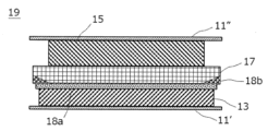
- FIG. 3 is an enlarged cross-sectional view of a single cell layer of a stacked secondary battery according to an embodiment of the present invention.
- FIG. 4 is an enlarged sectional view of a single cell layer of a stacked secondary battery according to another embodiment of the present invention.
- FIG. 5 is an enlarged cross-sectional view of a single cell layer of a stacked secondary battery according to another embodiment of the present invention.
- One form of the present invention includes a positive electrode in which a positive electrode active material layer containing a positive electrode active material capable of intercalating and deintercalating lithium ions is disposed on the surface of the positive electrode current collector, and a negative electrode current collector;
- a power generation element includes a negative electrode in which lithium metal is deposited on a negative electrode current collector, and a solid electrolyte layer interposed between the positive electrode and the negative electrode and containing a solid electrolyte, the solid electrolyte layer being the negative electrode current collector. At least a portion of the region of the main surface facing the body, where the positive electrode active material layer faces the negative electrode current collector, has lithium ion conductivity to suppress the reaction between the lithium metal and the solid electrolyte layer.
- An ion-conducting reaction suppression layer is provided, and the solid electrolyte layer extends to an end in the planar direction on the positive electrode side of the solid electrolyte layer, and extends to an end in the planar direction of the solid electrolyte layer on the negative electrode side.
- FIG. 1 is a perspective view showing the appearance of a flat stacked all-solid-state lithium secondary battery (hereinafter also simply referred to as a "stacked secondary battery"), which is an embodiment of the present invention.
- FIG. 2 is a sectional view taken along line 2-2 shown in FIG. Note that FIG. 2 shows a cross-sectional view of the stacked secondary battery during charging.
- the stacked secondary battery 10a has a flat rectangular shape, and a negative electrode current collector plate 25 and a positive electrode current collector plate 27 for extracting power are drawn out from both sides of the battery. .
- the power generation element 21 is surrounded by the battery exterior material (laminate film 29) of the stacked secondary battery 10a, and the periphery thereof is heat-sealed. It is sealed in a state where it is pulled out to the outside.
- the current collector plates (25, 27) shown in FIG. 27 may be divided into a plurality of parts and taken out from each side.
- the power generation element 21 of the stacked secondary battery 10a of this embodiment includes a negative electrode in which negative electrode active material layers 13 containing lithium metal are disposed on both sides of a negative electrode current collector 11', and a solid electrolyte layer. 17'' and a positive electrode in which positive electrode active material layers 15 containing a lithium-transition metal composite oxide are arranged on both sides of a positive electrode current collector 11''.
- a negative electrode active The negative electrode, the solid electrolyte layer, and the positive electrode are stacked in this order such that the material layer 13 and the adjacent positive electrode active material layer 15 face each other with the solid electrolyte layer 17 in between. , the solid electrolyte layer, and the positive electrode constitute one single cell layer 19. Therefore, in the stacked secondary battery 10a shown in FIG. It can also be said that it has a configuration in which
- a negative current collector plate 25 and a positive current collector plate 27 that are electrically connected to each electrode are attached to the negative electrode current collector 11' and the positive electrode current collector 11'', respectively. It has a structure in which the negative electrode current collector plate 25 and the positive electrode current collector plate 27 are sandwiched and lead out to the outside of the laminate film 29.
- the negative electrode current collector plate 25 and the positive electrode current collector plate 27 are connected to a negative electrode terminal lead and a positive electrode terminal lead (not shown), respectively, as necessary. ) may be attached to the negative electrode current collector 11' and the positive electrode current collector 11'' of each electrode by ultrasonic welding, resistance welding, or the like.
- lithium secondary battery according to one aspect of the present invention has been described using a stacked type (internal parallel connection type) all-solid-state lithium secondary battery as an example.
- type of lithium secondary battery to which the present invention is applicable is not particularly limited, and the present invention is also applicable to bipolar type lithium secondary batteries.
- FIG. 3 is an enlarged cross-sectional view of a single cell layer 19 of a stacked secondary battery according to an embodiment of the present invention.
- the unit cell layer 19 constituting the stacked secondary battery 10a according to the present embodiment is a positive electrode composed of a positive electrode current collector 11'' and a positive electrode active material layer 15 disposed on the surface thereof.
- a solid electrolyte layer 17 containing a solid electrolyte is disposed on the surface of the positive electrode active material layer 15 opposite to the positive electrode current collector 11''.
- FIG. 3 is an enlarged cross-sectional view of a single cell layer 19 of a stacked secondary battery according to an embodiment of the present invention.
- the unit cell layer 19 constituting the stacked secondary battery 10a according to the present embodiment is a positive electrode composed of a positive electrode current collector 11'' and a positive electrode active material layer 15 disposed on the surface thereof.
- a solid electrolyte layer 17 containing a solid electrolyte is disposed on the surface of the positive electrode active
- the solid electrolyte layer 17 is located on the main surface facing the negative electrode current collector 11', and the positive electrode active material layer 15 is located in a region including the entire region facing the negative electrode current collector 11'.
- a carbon black layer 18a containing carbon black nanoparticles is provided (in other words, the size is one size larger than the positive electrode active material layer 15 when the power generation element 21 is viewed in plan). Since the carbon black constituting the carbon black layer 18a has lithium ion conductivity, the carbon black layer 18a can conduct lithium ions. Therefore, the arrangement of the carbon black layer 18a does not hinder the progress of the battery reaction.
- the carbon black layer 18a also has the function of suppressing the reaction between the lithium metal (negative electrode active material layer 13) deposited on the negative electrode current collector 11' during charging and the solid electrolyte contained in the solid electrolyte layer 17. ing. Therefore, it can be said that the carbon black layer 18a functions as an ion conductive reaction suppression layer.
- the unit cell layer 19 constituting the stacked secondary battery 10a on the positive electrode side (upper side in FIG. 3) of the solid electrolyte layer 17, up to the end in the plane direction.
- a solid electrolyte layer 17 extends.
- a resin layer 18b made of a resin sheet is provided at the in-plane end portion of the solid electrolyte layer 17 on the negative electrode side (lower side in FIG. 3) over the entire circumference of the end portion.
- the resin constituting this resin layer 18b is a material that does not have lithium ion conductivity. Therefore, the resin layer 18b functions as an ion permeation suppressing layer that suppresses permeation of lithium ions.
- the resin layer 18b (ion permeation suppression layer) covers the entire circumference of the power generation element 21 (single cell layer 19) in a plan view (viewed from the stacking direction). ) are arranged so that they overlap.
- the resin layer 18b ion permeation suppressing layer
- the carbon black layer 18a ion conductive reaction suppressing layer
- No gaps are formed in the plane direction with respect to the suppression layer, and local precipitation of lithium metal (generation of dendrites) can be suppressed.
- the ion permeation suppressing layer at the end, it is possible to suppress the growth of dendrites at the end of the ion conductive reaction suppressing layer.
- an ion permeation suppressing layer is provided at the end in the planar direction, while on the positive electrode side, the solid electrolyte layer is present up to the end in the planar direction. It is possible to prevent the generation of dendrites caused by cracks in the ion conductive reaction suppression layer that occur in the process.
- the positive electrode active material layer 15 is provided between the solid electrolyte layer 17 and the positive electrode current collector 11''.
- the solid electrolyte layer It can be said that 17 faces the positive electrode current collector 11'' with the positive electrode active material layer 15 in between.
- a negative electrode active material layer 13 and a carbon black layer 18a are provided between the solid electrolyte layer 17 and the negative electrode current collector 11'.
- the solid electrolyte layer 17 faces the negative electrode current collector 11' with the negative electrode active material layer 13 and the carbon black layer 18a (ion conductive reaction suppression layer) in between.
- a stacked secondary battery 10a includes a power generation element 21 sealed in a laminate film 29 shown in FIG. 1, and a power generation element 21 sealed in the laminate film 29 sandwiched between two plate-like members. , it is preferable that they are further fastened using a fastening member.
- the plate member and the fastening member function as a pressure member that presses (restricts) the power generation element 21 in the stacking direction thereof.
- the plate-like member include metal plates and resin plates.
- fastening members include bolts and nuts.
- the pressurizing member is not particularly limited as long as it is a member that can pressurize the power generation elements 21 in the stacking direction thereof.
- a combination of a plate made of a rigid material, such as a plate-shaped member, and the above-mentioned fastening member is used as the pressure member.
- the fastening member not only bolts and nuts but also a tension plate or the like that fixes the end of a plate-like member so as to restrain the power generation element 21 in the stacking direction thereof may be used.
- the lower limit of the load applied to the power generation element 21 is, for example, 0.1 MPa or more, preferably 1 MPa or more, more preferably 3 MPa or more, and still more preferably It is 5 MPa or more.
- the upper limit of the confining pressure in the stacking direction of the power generating elements is, for example, 100 MPa or less, preferably 70 MPa or less, more preferably 40 MPa or less, and still more preferably 10 MPa or less.
- the positive electrode current collector and the negative electrode current collector are conductive members that function as electron flow paths during battery reactions (charging and discharging), and have, for example, a thin plate (foil) shape.
- the negative electrode current collector faces the positive electrode current collector with the power generation element (solid electrolyte layer) in between.
- the materials constituting the positive electrode current collector and the negative electrode current collector for example, metal or conductive resin is employed.
- metals examples include aluminum (Al), nickel (Ni), iron (Fe), stainless steel (SUS), titanium (Ti), and copper (Cu).
- a cladding material of nickel and aluminum, a cladding material of copper and aluminum, etc. may be used.
- it may be a foil whose metal surface is coated with aluminum.
- aluminum, stainless steel, copper, and nickel are preferred from the viewpoint of electronic conductivity, battery operating potential, and the like.
- examples of the resin having conductivity include resins in which a conductive filler is added to a non-conductive polymer material.
- the thickness of the positive electrode current collector and the negative electrode current collector is not particularly limited, but is 10 to 100 ⁇ m as an example.
- the positive electrode current collector and the negative electrode current collector may have a single-layer structure made of a single material, or may have a laminated structure in which layers made of these materials are appropriately combined. From the viewpoint of weight reduction, it is preferable that the positive electrode current collector and the negative electrode current collector contain at least a conductive resin made of a resin having conductivity. Further, from the viewpoint of blocking the movement of lithium ions between the cell layers, a metal layer may be provided on a part of the positive electrode current collector and the negative electrode current collector.
- the planar shape of the positive electrode current collector and the negative electrode current collector is, for example, a rectangular rectangle, a circle, or an ellipse. For example, the positive electrode current collector and the negative electrode current collector have approximately the same planar size.
- the positive electrode constituting the lithium secondary battery according to this embodiment has a positive electrode active material layer containing a positive electrode active material capable of inserting and extracting lithium ions.
- the positive electrode active material layer 15 is preferably formed using an NMC composite oxide such as NMC811 (nickel cobalt lithium manganate; LiNi 0.8 Co 0.1 Mn 0.1 O 2 ) as a main raw material.
- NMC composite oxide such as NMC811 (nickel cobalt lithium manganate; LiNi 0.8 Co 0.1 Mn 0.1 O 2 ) as a main raw material.
- the positive electrode active material layer 15 includes a positive electrode active material layer containing sulfur.
- the type of positive electrode active material containing sulfur is not particularly limited, but in addition to elemental sulfur (S), particles or thin films of organic sulfur compounds or inorganic sulfur compounds can be mentioned. Any material may be used as long as it can release lithium ions during charging and occlude lithium ions during discharging.
- the thickness (size in the stacking direction) of the positive electrode active material layer 15 varies depending on the configuration of the intended lithium secondary battery, but is preferably within the range of 0.1 to 1000 ⁇ m, more preferably 40 ⁇ m. ⁇ 100 ⁇ m.
- the content of the positive electrode active material in the positive electrode active material layer is not particularly limited, but is preferably in the range of 30 to 99% by mass, and preferably in the range of 40 to 90% by mass. More preferably, it is within the range of 45 to 80% by mass.
- the positive electrode active material layer 15 preferably further includes a solid electrolyte.
- solid electrolytes include sulfide solid electrolytes, resin solid electrolytes, and oxide solid electrolytes.
- the solid electrolyte refers to a material mainly composed of an ion conductor capable of ion conduction in a solid, and in particular, the lithium ion conductivity at room temperature (25 ° C.) is 1 ⁇ 10 -5 It refers to a material whose lithium ion conductivity is S/cm or more, and preferably has a lithium ion conductivity of 1 ⁇ 10 ⁇ 4 S/cm or more.
- the value of ionic conductivity can be measured by an AC impedance method.
- the solid electrolyte exhibits excellent lithium ion conductivity, and from the viewpoint of being able to better follow changes in the volume of the electrode active material due to charging and discharging, It is preferably a sulfide solid electrolyte containing S element, more preferably Li element, M element and S element, where the M element is P, Si, Ge, Sn, Ti, Zr, Nb, Al, Sb, Br. , Cl, and I, and more preferably a sulfide solid electrolyte containing S element, Li element, and P element.
- the sulfide solid electrolyte may have a Li 3 PS 4 skeleton, a Li 4 P 2 S 7 skeleton, or a Li 4 P 2 S 6 skeleton.
- Examples of the sulfide solid electrolyte having a Li3PS4 skeleton include LiI- Li3PS4 , LiI-LiBr- Li3PS4 , and Li3PS4 .
- examples of the sulfide solid electrolyte having a Li 4 P 2 S 7 skeleton include a Li-P-S solid electrolyte called LPS.
- LGPS represented by Li (4-x) Ge (1-x) P x S 4 (x satisfies 0 ⁇ x ⁇ 1) or the like may be used. More specifically, for example, LPS (Li 2 S-P 2 S 5 ), Li 7 P 3 S 11 , Li 3.2 P 0.96 S, Li 3.25 Ge 0.25 P 0.75 S 4 , Li 10 GeP 2 S 12 , or Li 6 PS 5 X (where X is Cl, Br or I). Note that the description "Li 2 S-P 2 S 5 " means a sulfide solid electrolyte using a raw material composition containing Li 2 S and P 2 S 5 , and the same applies to other descriptions.
- the sulfide solid electrolyte is preferably LPS (Li 2 S-P 2 S 5 ), Li 6 PS 5 X (wherein X is Cl, Br or I), Li 7 P 3 S 11 , Li 3.2 P 0.96 S and Li 3 PS 4 selected.
- the content of the solid electrolyte in the positive electrode active material layer is not particularly limited, but for example, it is preferably within the range of 1 to 70% by mass, and more preferably within the range of 10 to 60% by mass. It is preferably in the range of 20 to 55% by mass.
- the positive electrode active material layer may further contain at least one of a conductive additive and a binder.
- the thickness of the positive electrode active material layer varies depending on the configuration of the intended lithium secondary battery, but is preferably in the range of 0.1 to 1000 ⁇ m, more preferably 40 to 100 ⁇ m, for example.
- the solid electrolyte layer is a layer interposed between the positive electrode active material layer and the negative electrode current collector, and contains a solid electrolyte (usually as a main component).
- the solid electrolyte layer interposed between the positive electrode active material layer and the ion conductive reaction suppression layer contains a solid electrolyte as a main component.
- the solid electrolyte include sulfide solid electrolytes and oxide solid electrolytes, but sulfide solid electrolytes are preferred.
- the sulfide solid electrolyte include LPS-based (eg, argyrodite (Li 6 PS 5 Cl)) and LGPS-based (eg, Li 10 GeP 2 S 12 ) materials.
- the content of the solid electrolyte in the solid electrolyte layer is preferably in the range of 10 to 100% by mass, and more preferably in the range of 50 to 100% by mass, based on the total mass of the solid electrolyte layer. It is preferably in the range of 90 to 100% by mass.
- the thickness of the solid electrolyte layer varies depending on the configuration of the intended lithium secondary battery, but is preferably in the range of 0.1 to 1000 ⁇ m, more preferably 10 to 40 ⁇ m.
- the lithium secondary battery according to this embodiment is of a so-called lithium deposition type, in which lithium metal is deposited on the negative electrode current collector during the charging process.
- the layer made of lithium metal deposited on the negative electrode current collector during this charging process is the negative electrode active material layer of the lithium secondary battery according to this embodiment. Therefore, as the charging process progresses, the thickness of the negative electrode active material layer increases, and as the discharging process progresses, the thickness of the negative electrode active material layer decreases.
- the negative electrode active material layer does not need to be present at the time of complete discharge, in some cases, a negative electrode active material layer made of a certain amount of lithium metal may be provided at the time of complete discharge. Further, the thickness of the negative electrode active material layer (lithium metal layer) at the time of complete charging is not particularly limited, but is usually 0.1 to 1000 ⁇ m.
- the solid electrolyte layer 17 has a main surface facing the negative electrode current collector 11', and the positive electrode active material layer 15 has the main surface facing the negative electrode current collector 11'.
- An ion conductive reaction suppressing layer (carbon black layer 18a) is provided in at least a part of the region (preferably including the entire region).
- This ion conductive reaction suppression layer is a layer that has lithium ion conductivity and suppresses the reaction between lithium metal (negative electrode active material layer) and the solid electrolyte.
- a certain material “has lithium ion conductivity” means that the lithium ion conductivity of the material at 25° C. is 1 ⁇ 10 ⁇ 4 [S/cm] or more.
- a certain material “does not have lithium ion conductivity” it means that the lithium ion conductivity of the material at 25° C. is less than 1 ⁇ 10 ⁇ 4 [S/cm].
- ⁇ 10 ⁇ 4 [S/cm] is 1 ⁇ 10 ⁇ 4 [S/cm] or more, preferably 1.5 ⁇ 10 ⁇ 4 [S/cm] or more, more preferably 2.0 ⁇ 10 ⁇ 4 [S/cm] or more, still more preferably 2.5 ⁇ 10 ⁇ 4 [S/cm] or more, especially Preferably it is 3.0 ⁇ 10 ⁇ 4 [S/cm] or more.
- nanoparticles having lithium ion conductivity (herein, the nanoparticles as the constituent material of the ion conductive reaction suppression layer are simply referred to as "first nanoparticles”) ).
- first nanoparticles By including the first nanoparticles in the ion-conductive reaction-suppressing layer, a lithium secondary battery can be provided in which the ion-conducting reaction-suppressing layer has a particularly excellent function.
- nanoparticles refers to particles having an average particle diameter on the scale of nanometers (nm).
- the "average particle diameter" of nanoparticles is the particle diameter measured by observing a cross section of a layer containing nanoparticles with a scanning electron microscope (SEM) (any two points on the contour line of the observed particle). It refers to the 50% cumulative diameter (D50) of the maximum distance between the two.
- the average particle diameter of the first nanoparticles is preferably 500 nm or less, more preferably 300 nm or less, even more preferably 150 nm or less, particularly preferably 100 nm or less, and most preferably 60 nm or less.
- a lithium secondary battery that is particularly excellent in suppressing the growth of dendrites can be provided.
- There is no particular restriction on the lower limit of the average particle diameter of the first nanoparticles but it is usually 10 nm or more, preferably 20 nm or more.
- Such first nanoparticles are selected from the group consisting of carbon, gold, platinum, palladium, silicon, silver, aluminum, bismuth, tin, and zinc, for example, from the viewpoint of having a particularly excellent function as an ion-conducting reaction-suppressing layer.
- the material preferably contains one or more elements selected from the following, and more preferably one or more of these elements alone or in an alloy.
- the first nanoparticles preferably contain carbon, and more preferably consist of simple carbon. Examples of such materials consisting of a simple substance of carbon include acetylene black, Vulcan (registered trademark), Black Pearl (registered trademark), carbon nanofiber, Ketjenblack (registered trademark), carbon nanotube, carbon nanohorn, and carbon nanotube. Examples include balloons and fullerenes. Note that when the ion conductive reaction suppression layer contains such nanoparticles, the layer may further contain a binder.
- the method of forming the ion conductive reaction suppression layer containing the first nanoparticles as described above on the surface of the negative electrode current collector side of the solid electrolyte layer There are no particular limitations on the method of forming the ion conductive reaction suppression layer containing the first nanoparticles as described above on the surface of the negative electrode current collector side of the solid electrolyte layer.
- a method may be adopted in which a slurry in which a binder is dispersed is applied to the surface of the solid electrolyte layer on the negative electrode current collector side, and the solvent is dried.
- the coating film obtained by coating the above slurry on the surface of a support such as stainless steel foil and drying the solvent is pasted to the surface of the negative electrode current collector side of the solid electrolyte layer using a technique such as hydrostatic pressing.
- the ion conductive reaction suppressing layer may be formed by peeling off the support.
- the ion conductive reaction suppression layer may be formed by forming a continuous layer containing any of the above-
- the ion-conductivity reaction suppression layer containing the above-mentioned first nanoparticles usually has electron conductivity. It is preferable that the ion conductive reaction suppression layer has electron conductivity in this way, since the resistance to rapid charging can be further improved.
- the ionically conductive reaction suppression layer is electronically insulating.
- electronically insulating constituent materials of the ion conductive reaction suppression layer include lithium halides (lithium fluoride (LiF), lithium chloride (LiCl), lithium bromide (LiBr), lithium iodide (LiI)), Composite metal oxides represented by Li-M-O (M is one or more metal elements selected from the group consisting of Mg, Au, Al, Sn and Zn), and Li-Ba- One or more lithium-containing compounds selected from the group consisting of TiO 3 composite oxides can be mentioned. Both of these materials are more stable than solid electrolytes with respect to reductive decomposition upon contact with lithium metal.
- the solid electrolyte constituting the solid electrolyte layer tends to undergo reductive decomposition when it comes into contact with lithium metal
- the lithium-containing compound as a constituent material of the ion conductive reaction suppression layer tends to undergo reductive decomposition when it comes into contact with lithium metal.
- the lithium-containing compound can also function as an ion conductive reaction suppression layer.
- a continuous layer containing the above-mentioned lithium-containing compound is formed by a method such as sputtering to suppress the ion conductive reaction. It can be a suppression layer.
- the average thickness of the ion-conductive reaction-suppressing layer is preferably 300 nm to 20 ⁇ m, more preferably 500 nm to 15 ⁇ m, and even more preferably is 1 to 10 ⁇ m. Further, when the layer is a continuous layer made of a lithium-containing compound formed by a method such as sputtering, the thickness is preferably 0.5 to 20 nm.
- the "average thickness" of the ion-conductive reaction-suppressing layer is defined as the arithmetic average value of the thicknesses measured at several to ten different locations on the ion-conductive reaction-suppressing layer that constitutes the lithium secondary battery. shall mean the calculated value.
- the Young's modulus of the ion conductive reaction suppression layer is preferably 2 GPa or more, more preferably 5 GPa or more, particularly preferably 8 GPa or more, and particularly preferably 10 GPa or more. Because the ion conductive reaction suppression layer exhibits such a high Young's modulus, even if dendrites are generated from lithium metal deposited during rapid charging, the dendrites will penetrate the solid electrolyte layer and form the positive electrode active material layer. It is possible to effectively prevent the occurrence of internal short circuits due to In addition, in this specification, the value of Young's modulus shall be adopted as the value measured based on JIS K 7161-1:2014.
- an ion permeation suppressing layer (resin layer 18b ) is also characteristic.
- This ion permeation suppressing layer is a layer that suppresses permeation of lithium ions. Therefore, by providing the ion permeation suppressing layer, even if dendrites are generated from lithium metal in the negative electrode active material layer 13, short circuits caused by the dendrites growing around the outer periphery of the solid electrolyte layer 17 can be prevented. The occurrence can be effectively prevented.
- the constituent material of the ion permeation suppressing layer is preferably a material that does not have lithium ion conductivity.
- the lithium ion conductivity at 25° C. of the constituent material of the ion permeation suppressing layer is less than 1 ⁇ 10 ⁇ 4 [S/cm], preferably 1 ⁇ 10 ⁇ 5 [S/cm].
- lithium ion conductivity of the constituent material of the ion permeation suppressing layer is within these ranges, the effect of suppressing the permeation of lithium ions is particularly high.
- the lithium ion conductivity of the constituent materials of the ion conductive reaction suppression layer is preferably 10 times or more, more preferably 100 times or more, even more preferably 300 times or more, and even more preferably 500 times or more the lithium ion conductivity (25°C) of the constituent material of the ion permeation suppressing layer. It is particularly preferable that it is twice or more.
- the lithium ion conductivity of each material differs to this extent, it can be said that the material exhibits a preferable lithium ion conductivity as a constituent material of each layer.
- constituent materials of the ion permeation suppressing layer include resin materials, rubber materials, and inorganic powders such as S-B-Na-based glass frit.
- resin materials and rubber materials especially resin materials
- resin materials or rubber materials examples include polybutylene terephthalate, polyethylene terephthalate, polyvinylidene fluoride (PVDF) (including compounds in which hydrogen atoms are replaced with other halogen elements), polyethylene, polypropylene, polymethyl Pentene, polybutene, polyethernitrile, polytetrafluoroethylene, polyacrylonitrile, polyimide, polyamide, ethylene-vinyl acetate copolymer, polyvinyl chloride, styrene-butadiene rubber (SBR), ethylene-propylene-diene copolymer, styrene ⁇ Thermoplastic polymers such as butadiene/styrene block copolymer and its hydrogenated product, styrene/isoprene/styrene block copolymer and its hydrogenated product, tetrafluoroethylene/hexafluoropropylene copolymer (FEP), tetrafluor
- nanoparticles that do not have lithium ion conductivity are also simply referred to as "second nanoparticles" are used as a constituent material of the ion permeation suppressing layer.
- the average particle diameter of the second nanoparticles is preferably 500 nm or less, more preferably 300 nm or less, even more preferably 150 nm or less, even more preferably 100 nm or less, particularly preferably 70 nm or less, Most preferably it is 40 nm or less.
- the average particle diameter of the second nanoparticles is 40 nm or less, a lithium secondary battery that is particularly excellent in suppressing the growth of dendrites can be provided.
- the lower limit of the average particle diameter of the second nanoparticles it is usually 10 nm or more, preferably 20 nm or more.
- the second nanoparticles preferably contain a metal oxide or nitride.
- metal oxides or nitrides include metal oxides or nitrides such as aluminum, silicon, magnesium, calcium, potassium, tin, sodium, boron, titanium, lead, zirconium, and yttrium.
- the second nanoparticles preferably contain oxides of these metals, and more preferably contain oxides of aluminum (aluminum oxide; alumina) or oxides of silicon (silicon oxide; silica). , more preferably contains alumina. Note that when the ion permeation suppressing layer contains such nanoparticles, the layer may further contain a binder.
- the Young's modulus of the ion permeation suppressing layer is approximately the same as the Young's modulus of the solid electrolyte layer (within ⁇ 10%). With such a configuration, it is possible to suppress cracking of the ion conductive reaction suppression layer during processes such as roll pressing during cell manufacturing.
- the above-described ion permeation suppressing layer on the negative electrode side end of the solid electrolyte layer there are no particular limitations on the method of forming the above-described ion permeation suppressing layer on the negative electrode side end of the solid electrolyte layer, but for example, the above-mentioned nanoparticles and, if necessary, a binder may be dispersed in a suitable solvent.
- One method is to apply a slurry to the surface of the end of the solid electrolyte layer, dry the solvent, and then perform a rolling process using a roll press machine to embed an ion permeation suppressing layer on the surface of the end of the solid electrolyte layer. It will be done.
- the coating film obtained by coating the above slurry on the surface of a support such as stainless steel foil and drying the solvent was bonded to the surface of the end of the solid electrolyte layer using a technique such as hydrostatic pressing.
- the ion permeation suppressing layer may be formed by performing a rolling treatment with or without peeling off the support.
- the ion permeation suppressing layer may be formed by disposing an insulating film such as various resin films and then performing a rolling treatment in the same manner.
- a counterbore may be provided in advance on the surface of the end portion of the solid electrolyte layer, and an ion permeation suppressing layer may be disposed or coated thereon.
- the solid electrolyte layer is composed of a sheet integrated with an ion permeation suppressing layer.
- the solid electrolyte layer includes a fibrous support so that the solid electrolyte layer is configured as a self-supporting sheet that is integrated with the ion permeation suppressing layer.
- the outer peripheral end of the ion conductive reaction suppression layer is located inside the outer peripheral end of the ion permeation suppression layer in plan view.
- the outer peripheral edge of the solid electrolyte layer coincides with the outer peripheral edge of the ion permeation suppressing layer in plan view.
- the outer peripheral end of the solid electrolyte layer may be located inside (or outside) the outer peripheral end of the ion permeation suppressing layer in plan view.
- the inner peripheral end of the ion permeation suppressing layer is located outside the outer peripheral end of the positive electrode active material layer in plan view.
- the positive electrode active material layer can be utilized more effectively.
- the inner circumferential edge of the ion permeation suppressing layer may coincide with the outer circumferential edge of the positive electrode active material layer in plan view, or may be located inside of this.
- the main surface of the solid electrolyte layer facing the negative electrode current collector and the negative electrode side surface of the ion permeation suppressing layer are arranged flush.
- the main surface of the solid electrolyte layer facing the negative electrode current collector and the negative electrode side surface of the ion permeation suppressing layer may not be arranged flush.
- the surface of the ion permeation suppressing layer on the negative electrode side may protrude further toward the negative electrode than the main surface of the solid electrolyte layer.
- the thickness of the ion permeation suppressing layer is preferably less than half the thickness of the solid electrolyte layer.
- the thickness of the ion permeation suppressing layer is more preferably 25% or less, more preferably 20% or less, even more preferably 15% or less, and 10% or less of the thickness of the solid electrolyte layer. It is particularly preferable that
- FIGS. 4 and 5 are enlarged cross-sectional views of a single cell layer of a stacked secondary battery according to another embodiment of the present invention.
- the thickness of the ion permeation suppressing layer (resin layer 18b) is greater at the outer peripheral end at the in-plane end on the negative electrode side than at the inner peripheral end at the in-plane end at the negative electrode side. It is thicker. With such a configuration, Li dendrites can be further suppressed at the end portions, and further improvement in cycle characteristics can be expected.
- the lithium secondary battery according to this embodiment is preferably an all-solid lithium secondary battery.
- All-solid-state lithium secondary batteries operate, for example, with a predetermined confining pressure applied in the stacking direction of power generation elements.
- a negative electrode active material layer made of lithium metal is formed between the negative electrode current collector and the ion conductive reaction suppression layer.
- lithium (Li) ions in the positive electrode active material layer pass through the solid electrolyte layer and are deposited as lithium metal on the surface of the negative electrode current collector.
- the all-solid-state lithium secondary battery is discharged, lithium ions from the negative electrode active material layer pass through the solid electrolyte layer and are occluded into the positive electrode active material. Therefore, the negative electrode active material layer usually disappears when the SOC is 0% (SOC 100% is a fully charged state).
- the lithium secondary battery according to this embodiment does not need to be an all-solid-state type. That is, the solid electrolyte layer may further contain a conventionally known liquid electrolyte (electrolyte solution).
- a conventionally known liquid electrolyte electrolyte solution
- the amount of liquid electrolyte (electrolyte) that can be included in the solid electrolyte layer is no particular limit to the amount of liquid electrolyte (electrolyte) that can be included in the solid electrolyte layer, but it is sufficient to maintain the shape of the solid electrolyte layer formed by the solid electrolyte and to prevent leakage of the liquid electrolyte (electrolyte). It is preferable that the amount is .
- the liquid electrolyte (electrolytic solution) a solution having a form in which a conventionally known lithium salt is dissolved in a conventionally known organic solvent is used.
- the liquid electrolyte (electrolyte solution) may further contain
- LiNi 0.8 Mn 0.1 Co 0.1 O 2 as a positive electrode active material, acetylene black as a conductive aid, and a sulfide solid electrolyte (LPS (Li 2 S-P 2 S 5 )), They were weighed to give a mass ratio of 70:5:25, mixed in an agate mortar in a glove box, and further mixed and stirred in a planetary ball mill. 2 parts by mass of styrene-butadiene rubber (SBR) was added to 100 parts by mass of the obtained mixed powder, and mesitylene was added as a solvent to prepare a positive electrode active material slurry. Next, the positive electrode active material slurry prepared above was applied to the surface of a stainless steel (SUS) foil serving as a positive electrode current collector, and dried to form a positive electrode active material layer, thereby producing a positive electrode.
- SUS stainless steel
- sulfide solid electrolyte LPS (Li 2 S-P 2 S 5 )
- SBR styrene-butadiene rubber
- mesitylene was added as a solvent to prepare a solid electrolyte slurry.
- the solid electrolyte slurry prepared above was applied to the surface of a stainless steel foil as a support and dried to form a solid electrolyte layer on the surface of the stainless steel foil.
- an insulating film (PET film) as an ion permeation suppressing layer is placed on the prepared solid electrolyte layer, and the thickness is made uniform by roll pressing, and an ion permeation suppressing layer made of PET film is placed around the entire circumference of the negative electrode side end of the solid electrolyte layer.
- PET film insulating film
- the positive electrode prepared above and the surface of the solid electrolyte layer on which the ion permeation suppressing layer is not placed are stacked so that they face each other, and then bonded together using a hydrostatic press (700 MPa, 25° C., 1 minute).
- the stainless steel foil on the solid electrolyte layer side was peeled off to obtain a laminate of positive electrode current collector/positive electrode active material layer/solid electrolyte layer (including the ion permeation suppressing layer).
- carbon black nanoparticles were prepared as a constituent material of the ion conductive reaction suppression layer.
- 10 parts by mass of the same styrene-butadiene rubber (SBR) as described above was added, and mesitylene was added as a solvent to prepare a carbon black nanoparticle slurry.
- SBR styrene-butadiene rubber
- mesitylene was added as a solvent to prepare a carbon black nanoparticle slurry.
- the carbon black nanoparticle slurry prepared above was applied to the surface of a stainless steel foil as a support and dried to form a carbon black layer as an ion conductive reaction suppression layer on the surface of the stainless steel foil.
- the outer circumferential size of the carbon black layer is one size larger than the area where the positive electrode active material layer faces the negative electrode current collector, as shown in FIG. 3, and the outer circumferential size of the solid electrolyte layer It was made one size smaller than the .
- the solid electrolyte layer of the laminate of the positive electrode current collector/positive electrode active material layer/solid electrolyte layer (including the ion permeation suppressing layer) prepared above and the carbon black layer (ion conductive reaction suppressing layer) prepared above are then added. After stacking them so that they face each other, they are bonded together using a hydrostatic press (700 MPa, 25°C, 1 minute), and the stainless steel foil on the carbon black layer side is peeled off to form a carbon black layer in the center of the solid electrolyte layer. did. Finally, a stainless steel foil was placed as a negative electrode current collector so as to cover the carbon black layer formed above. The next battery was fabricated.
Landscapes
- Chemical & Material Sciences (AREA)
- Chemical Kinetics & Catalysis (AREA)
- Electrochemistry (AREA)
- General Chemical & Material Sciences (AREA)
- Engineering & Computer Science (AREA)
- Manufacturing & Machinery (AREA)
- Materials Engineering (AREA)
- Physics & Mathematics (AREA)
- Condensed Matter Physics & Semiconductors (AREA)
- General Physics & Mathematics (AREA)
- Inorganic Chemistry (AREA)
- Secondary Cells (AREA)
Abstract
Le but de la présente invention est de fournir un moyen permettant de supprimer une diminution de la capacité de la batterie ou l'apparition d'un court-circuit dans une batterie secondaire au lithium basée sur un dépôt de lithium. Un mode de réalisation de la présente invention concerne une batterie secondaire au lithium pourvue d'un élément de génération d'énergie comprenant : une électrode positive formée par la disposition, sur la surface d'un collecteur de courant d'électrode positive, d'une couche de matériau actif d'électrode positive contenant un matériau actif d'électrode positive permettant l'intercalation/désintercalation d'ions lithium; une électrode négative pourvue d'un collecteur de courant d'électrode négative et dans laquelle du lithium métallique est déposé sur le collecteur de courant d'électrode négative pendant la charge; une couche d'électrolyte solide interposée entre l'électrode positive et l'électrode négative, et contenant un électrolyte solide. Cette batterie secondaire au lithium est caractérisée en ce que : une couche de suppression de réaction conductrice d'ions qui présente une conductivité des ions lithium et supprime une réaction entre le lithium métallique et l'électrolyte solide est disposée sur au moins une partie d'une région où la couche de matériau actif d'électrode positive est opposée au collecteur de courant d'électrode négative, sur une surface principale où la couche d'électrolyte solide est opposée au collecteur de courant d'électrode négative; l'électrolyte solide s'étend jusqu'à une extrémité de direction plane du côté de l'électrode positive de la couche d'électrolyte solide; une couche de suppression de perméation des ions lithium est disposée à l'extrémité de direction plane du côté de l'électrode négative de la couche d'électrolyte solide; et au moins une partie de la couche de suppression de perméation des ions chevauche la couche de suppression de réaction conductrice des ions dans une vue en plan.
Priority Applications (1)
| Application Number | Priority Date | Filing Date | Title |
|---|---|---|---|
| PCT/IB2022/000283 WO2023218218A1 (fr) | 2022-05-13 | 2022-05-13 | Batterie secondaire au lithium |
Applications Claiming Priority (1)
| Application Number | Priority Date | Filing Date | Title |
|---|---|---|---|
| PCT/IB2022/000283 WO2023218218A1 (fr) | 2022-05-13 | 2022-05-13 | Batterie secondaire au lithium |
Publications (1)
| Publication Number | Publication Date |
|---|---|
| WO2023218218A1 true WO2023218218A1 (fr) | 2023-11-16 |
Family
ID=88729821
Family Applications (1)
| Application Number | Title | Priority Date | Filing Date |
|---|---|---|---|
| PCT/IB2022/000283 WO2023218218A1 (fr) | 2022-05-13 | 2022-05-13 | Batterie secondaire au lithium |
Country Status (1)
| Country | Link |
|---|---|
| WO (1) | WO2023218218A1 (fr) |
Citations (5)
| Publication number | Priority date | Publication date | Assignee | Title |
|---|---|---|---|---|
| JP2015125893A (ja) * | 2013-12-26 | 2015-07-06 | トヨタ自動車株式会社 | 全固体電池の製造方法 |
| JP2015170595A (ja) * | 2014-03-04 | 2015-09-28 | 現代自動車株式会社Hyundaimotor Company | リチウムを用いた電池の製造方法 |
| JP2020135974A (ja) * | 2019-02-14 | 2020-08-31 | 日産自動車株式会社 | 全固体電池 |
| WO2021074741A1 (fr) * | 2019-10-18 | 2021-04-22 | 株式会社半導体エネルギー研究所 | Batterie secondaire et son procédé de production |
| JP2021072262A (ja) * | 2019-11-01 | 2021-05-06 | 日産自動車株式会社 | 全固体電池 |
-
2022
- 2022-05-13 WO PCT/IB2022/000283 patent/WO2023218218A1/fr unknown
Patent Citations (5)
| Publication number | Priority date | Publication date | Assignee | Title |
|---|---|---|---|---|
| JP2015125893A (ja) * | 2013-12-26 | 2015-07-06 | トヨタ自動車株式会社 | 全固体電池の製造方法 |
| JP2015170595A (ja) * | 2014-03-04 | 2015-09-28 | 現代自動車株式会社Hyundaimotor Company | リチウムを用いた電池の製造方法 |
| JP2020135974A (ja) * | 2019-02-14 | 2020-08-31 | 日産自動車株式会社 | 全固体電池 |
| WO2021074741A1 (fr) * | 2019-10-18 | 2021-04-22 | 株式会社半導体エネルギー研究所 | Batterie secondaire et son procédé de production |
| JP2021072262A (ja) * | 2019-11-01 | 2021-05-06 | 日産自動車株式会社 | 全固体電池 |
Similar Documents
| Publication | Publication Date | Title |
|---|---|---|
| EP2592674B1 (fr) | Assemblage d'électrode pour un dispositif de stockage électrique et dispositif de stockage électrique. | |
| JP5930035B2 (ja) | 全固体電池及びその製造方法 | |
| JP7274300B2 (ja) | 全固体電池 | |
| JP7102831B2 (ja) | 正極及びリチウムイオン二次電池 | |
| JP5806335B2 (ja) | 電極体及びその製造方法 | |
| JP2015005421A (ja) | 電極体及び全固体電池 | |
| JP7182159B2 (ja) | 全固体電池 | |
| JP7398269B2 (ja) | 全固体リチウムイオン二次電池 | |
| JP7386046B2 (ja) | 全固体電池 | |
| JP2021192354A (ja) | 全固体電池 | |
| JP2021096928A (ja) | 複合材料、複合材料の製造方法、電極の製造方法、正極およびリチウムイオン二次電池 | |
| JP2021106095A (ja) | 全固体電池およびその製造方法 | |
| WO2023218218A1 (fr) | Batterie secondaire au lithium | |
| JP7398231B2 (ja) | 全固体電池システム | |
| JP7414520B2 (ja) | 全固体電池用電極 | |
| WO2023111680A1 (fr) | Batterie secondaire au lithium | |
| WO2023223067A1 (fr) | Batterie secondaire au lithium | |
| WO2022210191A1 (fr) | Batterie secondaire au lithium | |
| JP2021048045A (ja) | 全固体電池 | |
| WO2024018247A1 (fr) | Procédé de fabrication de batterie secondaire au lithium | |
| WO2024028622A1 (fr) | Batterie secondaire | |
| WO2023223065A1 (fr) | Batterie secondaire | |
| JP7407014B2 (ja) | 全固体リチウムイオン二次電池 | |
| EP4333110A1 (fr) | Batterie secondaire au lithium | |
| JP2023150044A (ja) | リチウム二次電池 |
Legal Events
| Date | Code | Title | Description |
|---|---|---|---|
| 121 | Ep: the epo has been informed by wipo that ep was designated in this application |
Ref document number: 22940953 Country of ref document: EP Kind code of ref document: A1 |