WO2023218218A1 - Lithium secondary battery - Google Patents
Lithium secondary battery Download PDFInfo
- Publication number
- WO2023218218A1 WO2023218218A1 PCT/IB2022/000283 IB2022000283W WO2023218218A1 WO 2023218218 A1 WO2023218218 A1 WO 2023218218A1 IB 2022000283 W IB2022000283 W IB 2022000283W WO 2023218218 A1 WO2023218218 A1 WO 2023218218A1
- Authority
- WO
- WIPO (PCT)
- Prior art keywords
- layer
- solid electrolyte
- negative electrode
- positive electrode
- lithium
- Prior art date
Links
- 229910052744 lithium Inorganic materials 0.000 title claims abstract description 96
- WHXSMMKQMYFTQS-UHFFFAOYSA-N Lithium Chemical compound [Li] WHXSMMKQMYFTQS-UHFFFAOYSA-N 0.000 title claims abstract description 65
- 239000007784 solid electrolyte Substances 0.000 claims abstract description 130
- 150000002500 ions Chemical class 0.000 claims abstract description 124
- 238000006243 chemical reaction Methods 0.000 claims abstract description 62
- 239000007774 positive electrode material Substances 0.000 claims abstract description 56
- HBBGRARXTFLTSG-UHFFFAOYSA-N Lithium ion Chemical compound [Li+] HBBGRARXTFLTSG-UHFFFAOYSA-N 0.000 claims abstract description 51
- 229910001416 lithium ion Inorganic materials 0.000 claims abstract description 51
- 238000010248 power generation Methods 0.000 claims abstract description 18
- 238000009831 deintercalation Methods 0.000 claims abstract description 4
- 238000009830 intercalation Methods 0.000 claims abstract description 4
- 239000000463 material Substances 0.000 claims description 56
- 230000001629 suppression Effects 0.000 claims description 53
- 230000002093 peripheral effect Effects 0.000 claims description 22
- 229920005989 resin Polymers 0.000 claims description 22
- 239000011347 resin Substances 0.000 claims description 22
- 230000007423 decrease Effects 0.000 abstract description 7
- 230000008021 deposition Effects 0.000 abstract description 7
- 230000002687 intercalation Effects 0.000 abstract 1
- 150000002641 lithium Chemical class 0.000 abstract 1
- 239000010410 layer Substances 0.000 description 304
- 239000002105 nanoparticle Substances 0.000 description 32
- 239000006229 carbon black Substances 0.000 description 22
- 238000000034 method Methods 0.000 description 22
- 239000000470 constituent Substances 0.000 description 21
- 239000007773 negative electrode material Substances 0.000 description 19
- 210000001787 dendrite Anatomy 0.000 description 16
- 239000002203 sulfidic glass Substances 0.000 description 14
- 210000004027 cell Anatomy 0.000 description 13
- 229920001973 fluoroelastomer Polymers 0.000 description 13
- 239000011888 foil Substances 0.000 description 12
- 239000002245 particle Substances 0.000 description 12
- 229910001220 stainless steel Inorganic materials 0.000 description 12
- 239000010935 stainless steel Substances 0.000 description 12
- 229910018130 Li 2 S-P 2 S 5 Inorganic materials 0.000 description 11
- 229910052782 aluminium Inorganic materials 0.000 description 11
- 239000002002 slurry Substances 0.000 description 11
- OKTJSMMVPCPJKN-UHFFFAOYSA-N Carbon Chemical compound [C] OKTJSMMVPCPJKN-UHFFFAOYSA-N 0.000 description 9
- XAGFODPZIPBFFR-UHFFFAOYSA-N aluminium Chemical compound [Al] XAGFODPZIPBFFR-UHFFFAOYSA-N 0.000 description 9
- -1 lithium halides Chemical class 0.000 description 8
- 238000004519 manufacturing process Methods 0.000 description 8
- 229910052751 metal Inorganic materials 0.000 description 8
- 239000002904 solvent Substances 0.000 description 8
- PXHVJJICTQNCMI-UHFFFAOYSA-N Nickel Chemical compound [Ni] PXHVJJICTQNCMI-UHFFFAOYSA-N 0.000 description 7
- 150000001875 compounds Chemical class 0.000 description 7
- 239000002184 metal Substances 0.000 description 7
- 229920001577 copolymer Polymers 0.000 description 6
- 238000000151 deposition Methods 0.000 description 6
- 238000003825 pressing Methods 0.000 description 6
- 239000011230 binding agent Substances 0.000 description 5
- 229910052799 carbon Inorganic materials 0.000 description 5
- 239000003792 electrolyte Substances 0.000 description 5
- 239000010408 film Substances 0.000 description 5
- 239000011244 liquid electrolyte Substances 0.000 description 5
- 229910052710 silicon Inorganic materials 0.000 description 5
- 229910052718 tin Inorganic materials 0.000 description 5
- 239000011135 tin Substances 0.000 description 5
- CURLTUGMZLYLDI-UHFFFAOYSA-N Carbon dioxide Chemical compound O=C=O CURLTUGMZLYLDI-UHFFFAOYSA-N 0.000 description 4
- VYPSYNLAJGMNEJ-UHFFFAOYSA-N Silicium dioxide Chemical compound O=[Si]=O VYPSYNLAJGMNEJ-UHFFFAOYSA-N 0.000 description 4
- XUIMIQQOPSSXEZ-UHFFFAOYSA-N Silicon Chemical compound [Si] XUIMIQQOPSSXEZ-UHFFFAOYSA-N 0.000 description 4
- 239000011248 coating agent Substances 0.000 description 4
- 238000000576 coating method Methods 0.000 description 4
- 239000010949 copper Substances 0.000 description 4
- 238000007599 discharging Methods 0.000 description 4
- 229920001971 elastomer Polymers 0.000 description 4
- 239000008151 electrolyte solution Substances 0.000 description 4
- 230000002706 hydrostatic effect Effects 0.000 description 4
- 239000005001 laminate film Substances 0.000 description 4
- 229910044991 metal oxide Inorganic materials 0.000 description 4
- 150000004706 metal oxides Chemical class 0.000 description 4
- 238000001556 precipitation Methods 0.000 description 4
- 238000005096 rolling process Methods 0.000 description 4
- 239000005060 rubber Substances 0.000 description 4
- 239000010703 silicon Substances 0.000 description 4
- 239000007787 solid Substances 0.000 description 4
- 229920003048 styrene butadiene rubber Polymers 0.000 description 4
- 229910052717 sulfur Inorganic materials 0.000 description 4
- 239000010936 titanium Substances 0.000 description 4
- RYGMFSIKBFXOCR-UHFFFAOYSA-N Copper Chemical compound [Cu] RYGMFSIKBFXOCR-UHFFFAOYSA-N 0.000 description 3
- NINIDFKCEFEMDL-UHFFFAOYSA-N Sulfur Chemical compound [S] NINIDFKCEFEMDL-UHFFFAOYSA-N 0.000 description 3
- ATJFFYVFTNAWJD-UHFFFAOYSA-N Tin Chemical compound [Sn] ATJFFYVFTNAWJD-UHFFFAOYSA-N 0.000 description 3
- 239000000654 additive Substances 0.000 description 3
- 229910052794 bromium Inorganic materials 0.000 description 3
- 229910052801 chlorine Inorganic materials 0.000 description 3
- 239000002131 composite material Substances 0.000 description 3
- 229910052802 copper Inorganic materials 0.000 description 3
- 238000000354 decomposition reaction Methods 0.000 description 3
- 230000006866 deterioration Effects 0.000 description 3
- 229910052740 iodine Inorganic materials 0.000 description 3
- AUHZEENZYGFFBQ-UHFFFAOYSA-N mesitylene Substances CC1=CC(C)=CC(C)=C1 AUHZEENZYGFFBQ-UHFFFAOYSA-N 0.000 description 3
- 125000001827 mesitylenyl group Chemical group [H]C1=C(C(*)=C(C([H])=C1C([H])([H])[H])C([H])([H])[H])C([H])([H])[H] 0.000 description 3
- 229910052759 nickel Inorganic materials 0.000 description 3
- 150000004767 nitrides Chemical class 0.000 description 3
- 230000002829 reductive effect Effects 0.000 description 3
- 238000004544 sputter deposition Methods 0.000 description 3
- 229910052719 titanium Inorganic materials 0.000 description 3
- 229920002799 BoPET Polymers 0.000 description 2
- KAKZBPTYRLMSJV-UHFFFAOYSA-N Butadiene Chemical compound C=CC=C KAKZBPTYRLMSJV-UHFFFAOYSA-N 0.000 description 2
- VGGSQFUCUMXWEO-UHFFFAOYSA-N Ethene Chemical compound C=C VGGSQFUCUMXWEO-UHFFFAOYSA-N 0.000 description 2
- 239000005977 Ethylene Substances 0.000 description 2
- 229910010859 LiI—LiBr—Li3PS4 Inorganic materials 0.000 description 2
- 239000002033 PVDF binder Substances 0.000 description 2
- KDLHZDBZIXYQEI-UHFFFAOYSA-N Palladium Chemical compound [Pd] KDLHZDBZIXYQEI-UHFFFAOYSA-N 0.000 description 2
- BQCADISMDOOEFD-UHFFFAOYSA-N Silver Chemical compound [Ag] BQCADISMDOOEFD-UHFFFAOYSA-N 0.000 description 2
- PPBRXRYQALVLMV-UHFFFAOYSA-N Styrene Chemical compound C=CC1=CC=CC=C1 PPBRXRYQALVLMV-UHFFFAOYSA-N 0.000 description 2
- RTAQQCXQSZGOHL-UHFFFAOYSA-N Titanium Chemical compound [Ti] RTAQQCXQSZGOHL-UHFFFAOYSA-N 0.000 description 2
- 239000006230 acetylene black Substances 0.000 description 2
- PNEYBMLMFCGWSK-UHFFFAOYSA-N aluminium oxide Inorganic materials [O-2].[O-2].[O-2].[Al+3].[Al+3] PNEYBMLMFCGWSK-UHFFFAOYSA-N 0.000 description 2
- 229910052797 bismuth Inorganic materials 0.000 description 2
- JCXGWMGPZLAOME-UHFFFAOYSA-N bismuth atom Chemical compound [Bi] JCXGWMGPZLAOME-UHFFFAOYSA-N 0.000 description 2
- 229910002092 carbon dioxide Inorganic materials 0.000 description 2
- 239000001569 carbon dioxide Substances 0.000 description 2
- 239000002041 carbon nanotube Substances 0.000 description 2
- 229910021393 carbon nanotube Inorganic materials 0.000 description 2
- 238000005253 cladding Methods 0.000 description 2
- 238000001035 drying Methods 0.000 description 2
- 125000002573 ethenylidene group Chemical group [*]=C=C([H])[H] 0.000 description 2
- 239000010419 fine particle Substances 0.000 description 2
- 239000010416 ion conductor Substances 0.000 description 2
- 239000007788 liquid Substances 0.000 description 2
- 229910000921 lithium phosphorous sulfides (LPS) Inorganic materials 0.000 description 2
- 229910003002 lithium salt Inorganic materials 0.000 description 2
- 159000000002 lithium salts Chemical class 0.000 description 2
- 150000002739 metals Chemical class 0.000 description 2
- 239000005486 organic electrolyte Substances 0.000 description 2
- 239000003960 organic solvent Substances 0.000 description 2
- BASFCYQUMIYNBI-UHFFFAOYSA-N platinum Chemical compound [Pt] BASFCYQUMIYNBI-UHFFFAOYSA-N 0.000 description 2
- 229920002493 poly(chlorotrifluoroethylene) Polymers 0.000 description 2
- 239000005023 polychlorotrifluoroethylene (PCTFE) polymer Substances 0.000 description 2
- 229920002981 polyvinylidene fluoride Polymers 0.000 description 2
- 239000002994 raw material Substances 0.000 description 2
- 229910052709 silver Inorganic materials 0.000 description 2
- 239000004332 silver Substances 0.000 description 2
- 239000011734 sodium Substances 0.000 description 2
- 229920006132 styrene block copolymer Polymers 0.000 description 2
- 239000011593 sulfur Substances 0.000 description 2
- BFKJFAAPBSQJPD-UHFFFAOYSA-N tetrafluoroethene Chemical group FC(F)=C(F)F BFKJFAAPBSQJPD-UHFFFAOYSA-N 0.000 description 2
- 238000003466 welding Methods 0.000 description 2
- 229910052725 zinc Inorganic materials 0.000 description 2
- 239000011701 zinc Substances 0.000 description 2
- 229910052726 zirconium Inorganic materials 0.000 description 2
- PCZZDNQPGUPCEY-UHFFFAOYSA-N 1,1,2,2-tetrafluoroethene;trifluoromethoxyethene Chemical group FC(F)=C(F)F.FC(F)(F)OC=C PCZZDNQPGUPCEY-UHFFFAOYSA-N 0.000 description 1
- WDEZYHHMIZHERM-UHFFFAOYSA-N 1,1-bis(fluoranyl)ethene Chemical compound FC(F)=C.FC(F)=C WDEZYHHMIZHERM-UHFFFAOYSA-N 0.000 description 1
- OQMIRQSWHKCKNJ-UHFFFAOYSA-N 1,1-difluoroethene;1,1,2,3,3,3-hexafluoroprop-1-ene Chemical group FC(F)=C.FC(F)=C(F)C(F)(F)F OQMIRQSWHKCKNJ-UHFFFAOYSA-N 0.000 description 1
- RXACTIULCNJUNO-UHFFFAOYSA-N 1,1-difluoroethene;1,1,2,3,3-pentafluoroprop-1-ene Chemical group FC(F)=C.FC(F)C(F)=C(F)F RXACTIULCNJUNO-UHFFFAOYSA-N 0.000 description 1
- COVXBJIKNGVTNV-UHFFFAOYSA-N 1-chloro-1,2,2-trifluoroethene;1,1-difluoroethene Chemical group FC(F)=C.FC(F)=C(F)Cl COVXBJIKNGVTNV-UHFFFAOYSA-N 0.000 description 1
- VSKJLJHPAFKHBX-UHFFFAOYSA-N 2-methylbuta-1,3-diene;styrene Chemical compound CC(=C)C=C.C=CC1=CC=CC=C1.C=CC1=CC=CC=C1 VSKJLJHPAFKHBX-UHFFFAOYSA-N 0.000 description 1
- ZOXJGFHDIHLPTG-UHFFFAOYSA-N Boron Chemical compound [B] ZOXJGFHDIHLPTG-UHFFFAOYSA-N 0.000 description 1
- XMWRBQBLMFGWIX-UHFFFAOYSA-N C60 fullerene Chemical class C12=C3C(C4=C56)=C7C8=C5C5=C9C%10=C6C6=C4C1=C1C4=C6C6=C%10C%10=C9C9=C%11C5=C8C5=C8C7=C3C3=C7C2=C1C1=C2C4=C6C4=C%10C6=C9C9=C%11C5=C5C8=C3C3=C7C1=C1C2=C4C6=C2C9=C5C3=C12 XMWRBQBLMFGWIX-UHFFFAOYSA-N 0.000 description 1
- OYPRJOBELJOOCE-UHFFFAOYSA-N Calcium Chemical compound [Ca] OYPRJOBELJOOCE-UHFFFAOYSA-N 0.000 description 1
- DGAQECJNVWCQMB-PUAWFVPOSA-M Ilexoside XXIX Chemical compound C[C@@H]1CC[C@@]2(CC[C@@]3(C(=CC[C@H]4[C@]3(CC[C@@H]5[C@@]4(CC[C@@H](C5(C)C)OS(=O)(=O)[O-])C)C)[C@@H]2[C@]1(C)O)C)C(=O)O[C@H]6[C@@H]([C@H]([C@@H]([C@H](O6)CO)O)O)O.[Na+] DGAQECJNVWCQMB-PUAWFVPOSA-M 0.000 description 1
- XEEYBQQBJWHFJM-UHFFFAOYSA-N Iron Chemical compound [Fe] XEEYBQQBJWHFJM-UHFFFAOYSA-N 0.000 description 1
- 229910018091 Li 2 S Inorganic materials 0.000 description 1
- 229910008039 Li-M-O Inorganic materials 0.000 description 1
- 229910008323 Li-P-S Inorganic materials 0.000 description 1
- 229910007860 Li3.25Ge0.25P0.75S4 Inorganic materials 0.000 description 1
- 229910015872 LiNi0.8Co0.1Mn0.1O2 Inorganic materials 0.000 description 1
- 229910015965 LiNi0.8Mn0.1Co0.1O2 Inorganic materials 0.000 description 1
- 229910006736 Li—P—S Inorganic materials 0.000 description 1
- FYYHWMGAXLPEAU-UHFFFAOYSA-N Magnesium Chemical compound [Mg] FYYHWMGAXLPEAU-UHFFFAOYSA-N 0.000 description 1
- 239000004952 Polyamide Substances 0.000 description 1
- 239000004698 Polyethylene Substances 0.000 description 1
- 239000004642 Polyimide Substances 0.000 description 1
- 239000004743 Polypropylene Substances 0.000 description 1
- ZLMJMSJWJFRBEC-UHFFFAOYSA-N Potassium Chemical compound [K] ZLMJMSJWJFRBEC-UHFFFAOYSA-N 0.000 description 1
- UCKMPCXJQFINFW-UHFFFAOYSA-N Sulphide Chemical compound [S-2] UCKMPCXJQFINFW-UHFFFAOYSA-N 0.000 description 1
- HCHKCACWOHOZIP-UHFFFAOYSA-N Zinc Chemical compound [Zn] HCHKCACWOHOZIP-UHFFFAOYSA-N 0.000 description 1
- QCWXUUIWCKQGHC-UHFFFAOYSA-N Zirconium Chemical compound [Zr] QCWXUUIWCKQGHC-UHFFFAOYSA-N 0.000 description 1
- HFCVPDYCRZVZDF-UHFFFAOYSA-N [Li+].[Co+2].[Ni+2].[O-][Mn]([O-])(=O)=O Chemical compound [Li+].[Co+2].[Ni+2].[O-][Mn]([O-])(=O)=O HFCVPDYCRZVZDF-UHFFFAOYSA-N 0.000 description 1
- 230000000996 additive effect Effects 0.000 description 1
- 229910045601 alloy Inorganic materials 0.000 description 1
- 239000000956 alloy Substances 0.000 description 1
- 229910003481 amorphous carbon Inorganic materials 0.000 description 1
- 229910052787 antimony Inorganic materials 0.000 description 1
- 230000000903 blocking effect Effects 0.000 description 1
- 229910052796 boron Inorganic materials 0.000 description 1
- 229910052791 calcium Inorganic materials 0.000 description 1
- 239000011575 calcium Substances 0.000 description 1
- 239000002134 carbon nanofiber Substances 0.000 description 1
- 239000006182 cathode active material Substances 0.000 description 1
- 239000002482 conductive additive Substances 0.000 description 1
- 239000011231 conductive filler Substances 0.000 description 1
- 229920001940 conductive polymer Polymers 0.000 description 1
- 238000005336 cracking Methods 0.000 description 1
- 230000001186 cumulative effect Effects 0.000 description 1
- 230000000694 effects Effects 0.000 description 1
- 239000007772 electrode material Substances 0.000 description 1
- 238000005516 engineering process Methods 0.000 description 1
- 239000003822 epoxy resin Substances 0.000 description 1
- 239000005038 ethylene vinyl acetate Substances 0.000 description 1
- XUCNUKMRBVNAPB-UHFFFAOYSA-N fluoroethene Chemical group FC=C XUCNUKMRBVNAPB-UHFFFAOYSA-N 0.000 description 1
- 229910003472 fullerene Inorganic materials 0.000 description 1
- 229910052732 germanium Inorganic materials 0.000 description 1
- 239000011521 glass Substances 0.000 description 1
- PCHJSUWPFVWCPO-UHFFFAOYSA-N gold Chemical compound [Au] PCHJSUWPFVWCPO-UHFFFAOYSA-N 0.000 description 1
- 229910052737 gold Inorganic materials 0.000 description 1
- 239000010931 gold Substances 0.000 description 1
- 229910052736 halogen Inorganic materials 0.000 description 1
- 150000002367 halogens Chemical class 0.000 description 1
- 125000004435 hydrogen atom Chemical group [H]* 0.000 description 1
- 239000003273 ketjen black Substances 0.000 description 1
- AMXOYNBUYSYVKV-UHFFFAOYSA-M lithium bromide Chemical compound [Li+].[Br-] AMXOYNBUYSYVKV-UHFFFAOYSA-M 0.000 description 1
- KWGKDLIKAYFUFQ-UHFFFAOYSA-M lithium chloride Chemical compound [Li+].[Cl-] KWGKDLIKAYFUFQ-UHFFFAOYSA-M 0.000 description 1
- PQXKHYXIUOZZFA-UHFFFAOYSA-M lithium fluoride Chemical compound [Li+].[F-] PQXKHYXIUOZZFA-UHFFFAOYSA-M 0.000 description 1
- HSZCZNFXUDYRKD-UHFFFAOYSA-M lithium iodide Chemical compound [Li+].[I-] HSZCZNFXUDYRKD-UHFFFAOYSA-M 0.000 description 1
- 239000011777 magnesium Substances 0.000 description 1
- 229910052749 magnesium Inorganic materials 0.000 description 1
- 239000002905 metal composite material Substances 0.000 description 1
- VNWKTOKETHGBQD-UHFFFAOYSA-N methane Chemical compound C VNWKTOKETHGBQD-UHFFFAOYSA-N 0.000 description 1
- 239000011812 mixed powder Substances 0.000 description 1
- 239000000203 mixture Substances 0.000 description 1
- 239000004570 mortar (masonry) Substances 0.000 description 1
- 239000002116 nanohorn Substances 0.000 description 1
- 229910052758 niobium Inorganic materials 0.000 description 1
- 150000002898 organic sulfur compounds Chemical class 0.000 description 1
- TWNQGVIAIRXVLR-UHFFFAOYSA-N oxo(oxoalumanyloxy)alumane Chemical compound O=[Al]O[Al]=O TWNQGVIAIRXVLR-UHFFFAOYSA-N 0.000 description 1
- 229910052763 palladium Inorganic materials 0.000 description 1
- 229910052698 phosphorus Inorganic materials 0.000 description 1
- 229910052697 platinum Inorganic materials 0.000 description 1
- 229920002587 poly(1,3-butadiene) polymer Polymers 0.000 description 1
- 229920001200 poly(ethylene-vinyl acetate) Polymers 0.000 description 1
- 229920002239 polyacrylonitrile Polymers 0.000 description 1
- 229920002647 polyamide Polymers 0.000 description 1
- 229920001083 polybutene Polymers 0.000 description 1
- 229920001707 polybutylene terephthalate Polymers 0.000 description 1
- 229920000647 polyepoxide Polymers 0.000 description 1
- 229920000573 polyethylene Polymers 0.000 description 1
- 229920000139 polyethylene terephthalate Polymers 0.000 description 1
- 239000005020 polyethylene terephthalate Substances 0.000 description 1
- 229920001721 polyimide Polymers 0.000 description 1
- 239000002861 polymer material Substances 0.000 description 1
- 229920000306 polymethylpentene Polymers 0.000 description 1
- 239000011116 polymethylpentene Substances 0.000 description 1
- 229920001155 polypropylene Polymers 0.000 description 1
- 229920001343 polytetrafluoroethylene Polymers 0.000 description 1
- 239000004810 polytetrafluoroethylene Substances 0.000 description 1
- 229920000915 polyvinyl chloride Polymers 0.000 description 1
- 239000004800 polyvinyl chloride Substances 0.000 description 1
- 239000011591 potassium Substances 0.000 description 1
- 229910052700 potassium Inorganic materials 0.000 description 1
- 239000000843 powder Substances 0.000 description 1
- 239000011241 protective layer Substances 0.000 description 1
- 238000012827 research and development Methods 0.000 description 1
- 239000000377 silicon dioxide Substances 0.000 description 1
- 229910052814 silicon oxide Inorganic materials 0.000 description 1
- 239000002356 single layer Substances 0.000 description 1
- 229910052708 sodium Inorganic materials 0.000 description 1
- 239000000243 solution Substances 0.000 description 1
- 239000000126 substance Substances 0.000 description 1
- 150000003464 sulfur compounds Chemical class 0.000 description 1
- 229920001169 thermoplastic Polymers 0.000 description 1
- 239000010409 thin film Substances 0.000 description 1
- 229910052723 transition metal Inorganic materials 0.000 description 1
- 125000000391 vinyl group Chemical group [H]C([*])=C([H])[H] 0.000 description 1
- 229920002554 vinyl polymer Polymers 0.000 description 1
- 238000010792 warming Methods 0.000 description 1
- 239000013585 weight reducing agent Substances 0.000 description 1
- 229910052727 yttrium Inorganic materials 0.000 description 1
- VWQVUPCCIRVNHF-UHFFFAOYSA-N yttrium atom Chemical compound [Y] VWQVUPCCIRVNHF-UHFFFAOYSA-N 0.000 description 1
Images


Classifications
-
- H—ELECTRICITY
- H01—ELECTRIC ELEMENTS
- H01M—PROCESSES OR MEANS, e.g. BATTERIES, FOR THE DIRECT CONVERSION OF CHEMICAL ENERGY INTO ELECTRICAL ENERGY
- H01M10/00—Secondary cells; Manufacture thereof
- H01M10/05—Accumulators with non-aqueous electrolyte
- H01M10/052—Li-accumulators
-
- H—ELECTRICITY
- H01—ELECTRIC ELEMENTS
- H01M—PROCESSES OR MEANS, e.g. BATTERIES, FOR THE DIRECT CONVERSION OF CHEMICAL ENERGY INTO ELECTRICAL ENERGY
- H01M10/00—Secondary cells; Manufacture thereof
- H01M10/05—Accumulators with non-aqueous electrolyte
- H01M10/056—Accumulators with non-aqueous electrolyte characterised by the materials used as electrolytes, e.g. mixed inorganic/organic electrolytes
- H01M10/0561—Accumulators with non-aqueous electrolyte characterised by the materials used as electrolytes, e.g. mixed inorganic/organic electrolytes the electrolyte being constituted of inorganic materials only
- H01M10/0562—Solid materials
-
- H—ELECTRICITY
- H01—ELECTRIC ELEMENTS
- H01M—PROCESSES OR MEANS, e.g. BATTERIES, FOR THE DIRECT CONVERSION OF CHEMICAL ENERGY INTO ELECTRICAL ENERGY
- H01M10/00—Secondary cells; Manufacture thereof
- H01M10/05—Accumulators with non-aqueous electrolyte
- H01M10/058—Construction or manufacture
- H01M10/0585—Construction or manufacture of accumulators having only flat construction elements, i.e. flat positive electrodes, flat negative electrodes and flat separators
-
- H—ELECTRICITY
- H01—ELECTRIC ELEMENTS
- H01M—PROCESSES OR MEANS, e.g. BATTERIES, FOR THE DIRECT CONVERSION OF CHEMICAL ENERGY INTO ELECTRICAL ENERGY
- H01M4/00—Electrodes
- H01M4/02—Electrodes composed of, or comprising, active material
- H01M4/13—Electrodes for accumulators with non-aqueous electrolyte, e.g. for lithium-accumulators; Processes of manufacture thereof
- H01M4/134—Electrodes based on metals, Si or alloys
-
- H—ELECTRICITY
- H01—ELECTRIC ELEMENTS
- H01M—PROCESSES OR MEANS, e.g. BATTERIES, FOR THE DIRECT CONVERSION OF CHEMICAL ENERGY INTO ELECTRICAL ENERGY
- H01M4/00—Electrodes
- H01M4/02—Electrodes composed of, or comprising, active material
- H01M4/36—Selection of substances as active materials, active masses, active liquids
- H01M4/38—Selection of substances as active materials, active masses, active liquids of elements or alloys
- H01M4/40—Alloys based on alkali metals
-
- Y—GENERAL TAGGING OF NEW TECHNOLOGICAL DEVELOPMENTS; GENERAL TAGGING OF CROSS-SECTIONAL TECHNOLOGIES SPANNING OVER SEVERAL SECTIONS OF THE IPC; TECHNICAL SUBJECTS COVERED BY FORMER USPC CROSS-REFERENCE ART COLLECTIONS [XRACs] AND DIGESTS
- Y02—TECHNOLOGIES OR APPLICATIONS FOR MITIGATION OR ADAPTATION AGAINST CLIMATE CHANGE
- Y02E—REDUCTION OF GREENHOUSE GAS [GHG] EMISSIONS, RELATED TO ENERGY GENERATION, TRANSMISSION OR DISTRIBUTION
- Y02E60/00—Enabling technologies; Technologies with a potential or indirect contribution to GHG emissions mitigation
- Y02E60/10—Energy storage using batteries
-
- Y—GENERAL TAGGING OF NEW TECHNOLOGICAL DEVELOPMENTS; GENERAL TAGGING OF CROSS-SECTIONAL TECHNOLOGIES SPANNING OVER SEVERAL SECTIONS OF THE IPC; TECHNICAL SUBJECTS COVERED BY FORMER USPC CROSS-REFERENCE ART COLLECTIONS [XRACs] AND DIGESTS
- Y02—TECHNOLOGIES OR APPLICATIONS FOR MITIGATION OR ADAPTATION AGAINST CLIMATE CHANGE
- Y02P—CLIMATE CHANGE MITIGATION TECHNOLOGIES IN THE PRODUCTION OR PROCESSING OF GOODS
- Y02P70/00—Climate change mitigation technologies in the production process for final industrial or consumer products
- Y02P70/50—Manufacturing or production processes characterised by the final manufactured product
Abstract
The purpose of the present invention is to provide a means making it possible to suppress a decrease in battery capacity or the occurrence of short-circuiting in a lithium deposition-based lithium secondary battery. One embodiment of the present invention pertains to a lithium secondary battery provided with a power generation element comprising: a positive electrode formed by arranging, on the surface of a positive electrode current collector, a positive electrode active material layer containing a positive electrode active material allowing for intercalation/deintercalation of lithium ions; a negative electrode which has a negative electrode current collector and in which lithium metal is deposited onto the negative electrode current collector during charging; a solid electrolyte layer that is interposed between the positive electrode and the negative electrode and contains a solid electrolyte. This lithium secondary battery is characterized in that: an ion-conducting reaction-suppressing layer that has lithium ion conductivity and suppresses a reaction between the lithium metal and the solid electrolyte is provided to at least part of a region where the positive electrode active material layer faces opposite the negative electrode current collector, on a principal surface where the solid electrolyte layer faces opposite the negative electrode current collector; the solid electrolyte extends as far as a plane direction end on the positive electrode side of the solid electrolyte layer; an ion permeation-suppressing layer for suppressing permeation of lithium ions is provided to the negative electrode-side plane direction end of the solid electrolyte layer; and at least part of the ion permeation-suppressing layer overlaps with the ion-conducting reaction-suppressing layer in plan view.
Description
本発明はリチウム二次電池に関する
The present invention relates to lithium secondary batteries
近年、地球温暖化に対処するため、二酸化炭素排出量の低減が切に望まれている。自動車業界では、電気自動車(EV)やハイブリッド電気自動車(HEV)の導入による二酸化炭素排出量の低減に期待が集まっており、これらの実用化の鍵を握るモータ駆動用二次電池などの非水電解質二次電池の開発が盛んに行われている。
In recent years, there has been a strong desire to reduce carbon dioxide emissions in order to combat global warming. In the automobile industry, expectations are high for reducing carbon dioxide emissions through the introduction of electric vehicles (EVs) and hybrid electric vehicles (HEVs), and non-aqueous batteries such as secondary batteries for motor drives hold the key to their practical application. Electrolyte secondary batteries are actively being developed.
モータ駆動用二次電池としては、携帯電話やノートパソコン等に使用される民生用リチウムイオン二次電池と比較して極めて高い出力特性、および高いエネルギーを有することが求められている。したがって、現実的な全ての電池の中で最も高い理論エネルギーを有するリチウムイオン二次電池が注目を集めており、現在急速に開発が進められている。
Secondary batteries for motor drives are required to have extremely high output characteristics and high energy compared to consumer lithium ion secondary batteries used in mobile phones, notebook computers, etc. Therefore, lithium ion secondary batteries, which have the highest theoretical energy of all practical batteries, are attracting attention and are currently being rapidly developed.
ここで、現在一般に普及しているリチウムイオン二次電池は、電解質に可燃性の有機電解液を用いている。このような液系リチウムイオン二次電池では、液漏れ、短絡、過充電などに対する安全対策が他の電池よりも厳しく求められる。
Here, the lithium ion secondary batteries that are currently in widespread use use a flammable organic electrolyte as the electrolyte. Such liquid-based lithium ion secondary batteries require more stringent safety measures against leakage, short circuits, overcharging, etc. than other batteries.
そこで近年、電解質に酸化物系や硫化物系の固体電解質を用いた全固体リチウム二次電池に関する研究開発が盛んに行われている。固体電解質は、固体中でイオン伝導が可能なイオン伝導体を主体として構成される材料である。このため、全固体リチウム二次電池においては、従来の液系リチウムイオン二次電池のように可燃性の有機電解液に起因する各種問題が原理的に発生しない。また一般に、高電位・大容量の正極材料、大容量の負極材料を用いると電池の出力密度およびエネルギー密度の大幅な向上が図れる。
Therefore, in recent years, research and development on all-solid-state lithium secondary batteries using oxide-based or sulfide-based solid electrolytes as electrolytes has been actively conducted. A solid electrolyte is a material mainly composed of an ion conductor capable of ion conduction in a solid state. Therefore, in principle, all-solid-state lithium secondary batteries do not suffer from various problems caused by flammable organic electrolytes, unlike conventional liquid-based lithium ion secondary batteries. Furthermore, in general, the use of high-potential, large-capacity positive electrode materials and large-capacity negative electrode materials can significantly improve the output density and energy density of the battery.
従来、全固体リチウム二次電池の1種として、充電過程において負極集電体上にリチウム金属を析出させる、いわゆるリチウム析出型のものが知られている。このようなリチウム析出型の全固体リチウム二次電池の充電過程においては、固体電解質層と負極集電体との間にリチウム金属が析出する。米国特許出願公開第2019/0157723号明細書には、リチウム二次電池の発電要素を構成する負極集電体と固体電解質層との間にアモルファスカーボンやケイ素、銀、スズ、アルミニウム、ビスマスなどの微粒子からなる微粒子層を配置する技術が開示されている。米国特許出願公開第2019/0157723号明細書によれば、このような構成とすることにより、充電時に上記微粒子層と負極集電体との間にリチウム金属が析出したときに当該微粒子層がリチウム金属層に対する保護層の役割を果たすとともに、リチウム金属層からのデンドライトの成長を抑制する結果、リチウム二次電池の短絡やそれに起因する容量の低下などが防止されるとされている。
Conventionally, as a type of all-solid-state lithium secondary battery, a so-called lithium deposition type battery is known in which lithium metal is deposited on a negative electrode current collector during the charging process. In the charging process of such a lithium deposition type all-solid lithium secondary battery, lithium metal is deposited between the solid electrolyte layer and the negative electrode current collector. US Patent Application Publication No. 2019/0157723 discloses that amorphous carbon, silicon, silver, tin, aluminum, bismuth, etc. Techniques for arranging a fine particle layer made of fine particles are disclosed. According to US Pat. It is said that it serves as a protective layer for the metal layer and suppresses the growth of dendrites from the lithium metal layer, thereby preventing short circuits in lithium secondary batteries and the resulting decrease in capacity.
しかしながら、本発明者らの検討によれば、米国特許出願公開第2019/0157723号明細書に記載された技術を用いたとしても、依然としてデンドライトの成長による電池容量の低下や短絡の発生を防止することができない場合があることが判明した。
However, according to the studies of the present inventors, even if the technology described in U.S. Patent Application Publication No. 2019/0157723 is used, it is still difficult to prevent a decrease in battery capacity and the occurrence of short circuits due to the growth of dendrites. It turns out that there are cases where this is not possible.
そこで、本発明は、リチウム析出型のリチウム二次電池において、電池容量の低下や短絡の発生を抑制しうる手段を提供することを目的とする。
Therefore, an object of the present invention is to provide a means for suppressing a decrease in battery capacity and occurrence of short circuit in a lithium deposition type lithium secondary battery.
本発明者らは、上記課題を解決すべく鋭意検討を行った。その結果、リチウム析出型の発電要素を備えたリチウム二次電池において、固体電解質層が負極集電体と対向する面の負極集電体側であって、正極活物質層が負極集電体と対向する領域にリチウムイオン伝導性を有しリチウム金属と固体電解質との反応を抑制するイオン伝導性反応抑制層を設けるとともに、当該固体電解質層の負極側の面方向端部にはリチウムイオンの透過を抑制するイオン透過抑制層を設け、正極側は面方向端部まで当該固体電解質層を設け、イオン透過抑制層の少なくとも一部をイオン伝導性反応抑制層で覆うことで上記課題が解決されうることを見出し、本発明を完成させるに至った。
The present inventors conducted extensive studies to solve the above problems. As a result, in a lithium secondary battery equipped with a lithium deposition type power generation element, the solid electrolyte layer is on the negative electrode current collector side of the surface facing the negative electrode current collector, and the positive electrode active material layer is on the negative electrode current collector side. An ion conductive reaction suppression layer is provided in the region where lithium ions are conductive and suppresses the reaction between the lithium metal and the solid electrolyte, and an ion conductive reaction suppression layer is provided in the area where the lithium ions pass through the solid electrolyte layer on the negative electrode side. The above problem can be solved by providing an ion permeation suppressing layer to suppress the ion permeation, providing the solid electrolyte layer on the positive electrode side up to the end in the plane direction, and covering at least a part of the ion permeation suppressing layer with an ion conductive reaction suppressing layer. They discovered this and completed the present invention.
すなわち、本発明の一形態は、リチウムイオンを吸蔵放出可能な正極活物質を含有する正極活物質層が正極集電体の表面に配置されてなる正極と、負極集電体を有し、充電時に前記負極集電体上にリチウム金属が析出する負極と、前記正極および前記負極の間に介在し、固体電解質を含有する固体電解質層とを有する発電要素を備えるリチウム二次電池に関する。そして、当該リチウム二次電池においては、前記固体電解質層が前記負極集電体と対向する主面の、前記正極活物質層が前記負極集電体と対向する領域の少なくとも一部に、リチウムイオン伝導性を有し前記リチウム金属と前記固体電解質との反応を抑制するイオン伝導性反応抑制層が設けられており、前記固体電解質層の前記正極側においては面方向端部まで前記固体電解質が延在し、前記固体電解質層の前記負極側の面方向端部にはリチウムイオンの透過を抑制するイオン透過抑制層が設けられており、かつ、前記イオン透過抑制層の少なくとも一部が、平面視で前記イオン伝導性反応抑制層と重複している点に特徴がある。
That is, one form of the present invention has a positive electrode in which a positive electrode active material layer containing a positive electrode active material capable of intercalating and deintercalating lithium ions is disposed on the surface of the positive electrode current collector, and a negative electrode current collector, and the charging The present invention relates to a lithium secondary battery including a power generation element having a negative electrode on which lithium metal is sometimes deposited on the negative electrode current collector, and a solid electrolyte layer interposed between the positive electrode and the negative electrode and containing a solid electrolyte. In the lithium secondary battery, lithium ions are added to at least a portion of the main surface of the solid electrolyte layer facing the negative electrode current collector and the area where the positive electrode active material layer faces the negative electrode current collector. An ion conductive reaction suppression layer that has conductivity and suppresses a reaction between the lithium metal and the solid electrolyte is provided, and on the positive electrode side of the solid electrolyte layer, the solid electrolyte extends to the end in the planar direction. An ion permeation suppressing layer for suppressing permeation of lithium ions is provided at the in-plane end portion of the solid electrolyte layer on the negative electrode side, and at least a part of the ion permeation suppressing layer is It is characterized in that it overlaps with the ion conductive reaction suppression layer.
本発明の一形態は、リチウムイオンを吸蔵放出可能な正極活物質を含有する正極活物質層が正極集電体の表面に配置されてなる正極と、負極集電体を有し、充電時に前記負極集電体上にリチウム金属が析出する負極と、前記正極および前記負極の間に介在し、固体電解質を含有する固体電解質層とを有する発電要素を備え、前記固体電解質層が前記負極集電体と対向する主面の、前記正極活物質層が前記負極集電体と対向する領域の少なくとも一部に、リチウムイオン伝導性を有し前記リチウム金属と前記固体電解質層との反応を抑制するイオン伝導性反応抑制層が設けられており、前記固体電解質層の前記正極側においては面方向端部まで前記固体電解質層が延在し、前記固体電解質層の前記負極側の面方向端部にはリチウムイオンの透過を抑制するイオン透過抑制層が設けられており、かつ、前記イオン透過抑制層の少なくとも一部が、平面視で前記イオン伝導性反応抑制層と重複している、リチウム二次電池である。本形態によれば、リチウム析出型のリチウム二次電池において、電池容量の低下や短絡の発生を抑制することができる。
One form of the present invention includes a positive electrode in which a positive electrode active material layer containing a positive electrode active material capable of intercalating and deintercalating lithium ions is disposed on the surface of the positive electrode current collector, and a negative electrode current collector; A power generation element includes a negative electrode in which lithium metal is deposited on a negative electrode current collector, and a solid electrolyte layer interposed between the positive electrode and the negative electrode and containing a solid electrolyte, the solid electrolyte layer being the negative electrode current collector. At least a portion of the region of the main surface facing the body, where the positive electrode active material layer faces the negative electrode current collector, has lithium ion conductivity to suppress the reaction between the lithium metal and the solid electrolyte layer. An ion-conducting reaction suppression layer is provided, and the solid electrolyte layer extends to an end in the planar direction on the positive electrode side of the solid electrolyte layer, and extends to an end in the planar direction of the solid electrolyte layer on the negative electrode side. is provided with an ion permeation suppressing layer that suppresses permeation of lithium ions, and at least a part of the ion permeation suppressing layer overlaps with the ion conductive reaction suppressing layer in plan view. It's a battery. According to this embodiment, in a lithium deposition type lithium secondary battery, a decrease in battery capacity and occurrence of a short circuit can be suppressed.
以下、図面を参照しながら、本形態を説明するが、本発明の技術的範囲は特許請求の範囲の記載に基づいて定められるべきであり、以下の形態のみに制限されない。なお、図面の寸法比率は、説明の都合上誇張されており、実際の比率とは異なる場合がある。以下で、各部の面が「面一に配置される」、または各部のサイズが「同じである(等しい)」と説明する場合、特段説明がないときには、これらは実質的に同じであればよく、製造上の誤差(たとえば、±5%程度)等が含まれる。
Hereinafter, the present embodiment will be described with reference to the drawings, but the technical scope of the present invention should be determined based on the claims and is not limited to the following embodiments. Note that the dimensional ratios in the drawings are exaggerated for convenience of explanation and may differ from the actual ratios. In the following, when we say that the surfaces of each part are "arranged flush" or that the sizes of each part are "the same (equal)", unless there is a special explanation, it is sufficient that they are substantially the same. , manufacturing errors (for example, about ±5%), etc.
図1は、本発明の一実施形態である扁平積層型の全固体リチウム二次電池(以下、単に「積層型二次電池」とも称する)の外観を表した斜視図である。図2は、図1に示す2−2線に沿う断面図である。なお、図2は、充電時における積層型二次電池の断面図を示している。
FIG. 1 is a perspective view showing the appearance of a flat stacked all-solid-state lithium secondary battery (hereinafter also simply referred to as a "stacked secondary battery"), which is an embodiment of the present invention. FIG. 2 is a sectional view taken along line 2-2 shown in FIG. Note that FIG. 2 shows a cross-sectional view of the stacked secondary battery during charging.
図1に示すように、積層型二次電池10aは、扁平矩形形状を有しており、その両側部からは電力を取り出すための負極集電板25、正極集電板27が引き出されている。発電要素21は、積層型二次電池10aの電池外装材(ラミネートフィルム29)によって包まれ、その周囲は熱融着されており、発電要素21は、負極集電板25および正極集電板27を外部に引き出した状態で密封されている。なお、図1に示す集電板(25、27)は、負極集電板25と正極集電板27とを同じ辺から引き出すようにしてもよいし、負極集電板25と正極集電板27とをそれぞれ複数に分けて、各辺から取り出すようにしてもよい。
As shown in FIG. 1, the stacked secondary battery 10a has a flat rectangular shape, and a negative electrode current collector plate 25 and a positive electrode current collector plate 27 for extracting power are drawn out from both sides of the battery. . The power generation element 21 is surrounded by the battery exterior material (laminate film 29) of the stacked secondary battery 10a, and the periphery thereof is heat-sealed. It is sealed in a state where it is pulled out to the outside. Note that the current collector plates (25, 27) shown in FIG. 27 may be divided into a plurality of parts and taken out from each side.
図2に示すように、本形態の積層型二次電池10aの発電要素21は、負極集電体11’の両面にリチウム金属を含む負極活物質層13が配置された負極と、固体電解質層17と、正極集電体11”の両面にリチウム遷移金属複合酸化物を含む正極活物質層15が配置された正極とを積層した構成を有している。具体的には、1つの負極活物質層13とこれに隣接する正極活物質層15とが、固体電解質層17を介して対向するようにして、負極、固体電解質層および正極がこの順に積層されている。これにより、隣接する負極、固体電解質層、および正極は、1つの単電池層19を構成する。したがって、図2に示す積層型二次電池10aは、単電池層19が複数積層されることで、電気的に並列接続されてなる構成を有するともいえる。
As shown in FIG. 2, the power generation element 21 of the stacked secondary battery 10a of this embodiment includes a negative electrode in which negative electrode active material layers 13 containing lithium metal are disposed on both sides of a negative electrode current collector 11', and a solid electrolyte layer. 17'' and a positive electrode in which positive electrode active material layers 15 containing a lithium-transition metal composite oxide are arranged on both sides of a positive electrode current collector 11''.Specifically, one negative electrode active The negative electrode, the solid electrolyte layer, and the positive electrode are stacked in this order such that the material layer 13 and the adjacent positive electrode active material layer 15 face each other with the solid electrolyte layer 17 in between. , the solid electrolyte layer, and the positive electrode constitute one single cell layer 19. Therefore, in the stacked secondary battery 10a shown in FIG. It can also be said that it has a configuration in which
負極集電体11’および正極集電体11”には、各電極(負極および正極)と導通される負極集電板25および正極集電板27がそれぞれ取り付けられ、ラミネートフィルム29の端部に挟まれるようにしてラミネートフィルム29の外部に導出される構造を有している。負極集電板25および正極集電板27は、それぞれ必要に応じて負極端子リードおよび正極端子リード(図示せず)を介して、各電極の負極集電体11’および正極集電体11”に超音波溶接や抵抗溶接等により取り付けられていてもよい。
A negative current collector plate 25 and a positive current collector plate 27 that are electrically connected to each electrode (negative electrode and positive electrode) are attached to the negative electrode current collector 11' and the positive electrode current collector 11'', respectively. It has a structure in which the negative electrode current collector plate 25 and the positive electrode current collector plate 27 are sandwiched and lead out to the outside of the laminate film 29.The negative electrode current collector plate 25 and the positive electrode current collector plate 27 are connected to a negative electrode terminal lead and a positive electrode terminal lead (not shown), respectively, as necessary. ) may be attached to the negative electrode current collector 11' and the positive electrode current collector 11'' of each electrode by ultrasonic welding, resistance welding, or the like.
なお、上記の説明では、積層型(内部並列接続タイプ)の全固体リチウム二次電池を例に挙げて本発明の一形態に係るリチウム二次電池の一実施形態を説明した。しかしながら、本発明が適用可能なリチウム二次電池の種類は特に制限されず、双極型(バイポーラ型)のリチウム二次電池にも適用可能である。
In the above description, an embodiment of a lithium secondary battery according to one aspect of the present invention has been described using a stacked type (internal parallel connection type) all-solid-state lithium secondary battery as an example. However, the type of lithium secondary battery to which the present invention is applicable is not particularly limited, and the present invention is also applicable to bipolar type lithium secondary batteries.
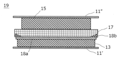
図3は、本発明の一実施形態に係る積層型二次電池の単電池層19の拡大断面図である。図3に示すように、本実施形態に係る積層型二次電池10aを構成する単電池層19は、正極集電体11”およびその表面に配置された正極活物質層15から構成される正極を有している。また、正極活物質層15の正極集電体11”とは反対側の面には、固体電解質を含む固体電解質層17が配置されている。また、図3に示す実施形態において、固体電解質層17が負極集電体11’と対向する主面の、正極活物質層15が負極集電体11’と対向する領域の全体を含む領域に(言い換えれば、発電要素21を平面視した際に正極活物質層15よりも一回り大きいサイズで)、カーボンブラックのナノ粒子を含むカーボンブラック層18aが設けられている。このカーボンブラック層18aを構成するカーボンブラックは、リチウムイオン伝導性を有していることから、カーボンブラック層18aはリチウムイオンを伝導することができる。このため、カーボンブラック層18aを配置したことで電池反応の進行が妨げられることはない。また、このカーボンブラック層18aは、充電時に負極集電体11’上に析出したリチウム金属(負極活物質層13)と固体電解質層17に含まれる固体電解質との反応を抑制する機能も有している。よって、当該カーボンブラック層18aは、イオン伝導性反応抑制層として機能するといえる。
FIG. 3 is an enlarged cross-sectional view of a single cell layer 19 of a stacked secondary battery according to an embodiment of the present invention. As shown in FIG. 3, the unit cell layer 19 constituting the stacked secondary battery 10a according to the present embodiment is a positive electrode composed of a positive electrode current collector 11'' and a positive electrode active material layer 15 disposed on the surface thereof. Further, a solid electrolyte layer 17 containing a solid electrolyte is disposed on the surface of the positive electrode active material layer 15 opposite to the positive electrode current collector 11''. In the embodiment shown in FIG. 3, the solid electrolyte layer 17 is located on the main surface facing the negative electrode current collector 11', and the positive electrode active material layer 15 is located in a region including the entire region facing the negative electrode current collector 11'. A carbon black layer 18a containing carbon black nanoparticles is provided (in other words, the size is one size larger than the positive electrode active material layer 15 when the power generation element 21 is viewed in plan). Since the carbon black constituting the carbon black layer 18a has lithium ion conductivity, the carbon black layer 18a can conduct lithium ions. Therefore, the arrangement of the carbon black layer 18a does not hinder the progress of the battery reaction. The carbon black layer 18a also has the function of suppressing the reaction between the lithium metal (negative electrode active material layer 13) deposited on the negative electrode current collector 11' during charging and the solid electrolyte contained in the solid electrolyte layer 17. ing. Therefore, it can be said that the carbon black layer 18a functions as an ion conductive reaction suppression layer.
また、図3に示すように、本実施形態に係る積層型二次電池10aを構成する単電池層19において、固体電解質層17の正極側(図3の上側)においては、面方向端部まで固体電解質層17が延在している。一方、固体電解質層17の負極側(図3の下側)の面方向端部には、端部の全周にわたって、樹脂シートからなる樹脂層18bが設けられている。この樹脂層18bを構成する樹脂は、リチウムイオン伝導性を有しない材料である。したがって、当該樹脂層18bは、リチウムイオンの透過を抑制するイオン透過抑制層として機能する。そして、上記樹脂層18b(イオン透過抑制層)は、全周にわたって、発電要素21(単電池層19)の平面視で(積層方向から見て)上記カーボンブラック層18a(イオン伝導性反応抑制層)と重複するように配置されている。このように樹脂層18b(イオン透過抑制層)の少なくとも一部がカーボンブラック層18a(イオン伝導性反応抑制層)と重複するように配置されていることにより、イオン伝導性反応抑制層とイオン透過抑制層との面方向に間隙が生じず、局所的なリチウム金属の析出(デンドライトの発生)を抑制することができる。また、イオン透過抑制層を端部に設けることによりイオン伝導性反応抑制層の端部におけるデンドライトの成長を抑制することができる。また、固体電解質層の負極側では面方向の端部にイオン透過抑制層を設ける一方で、正極側では面方向端部まで固体電解質層を存在させることにより、単電池層作製時のロールプレス工程において発生するイオン伝導性反応抑制層の割れに起因するデンドライトの発生を防止することができる。
Further, as shown in FIG. 3, in the unit cell layer 19 constituting the stacked secondary battery 10a according to the present embodiment, on the positive electrode side (upper side in FIG. 3) of the solid electrolyte layer 17, up to the end in the plane direction. A solid electrolyte layer 17 extends. On the other hand, a resin layer 18b made of a resin sheet is provided at the in-plane end portion of the solid electrolyte layer 17 on the negative electrode side (lower side in FIG. 3) over the entire circumference of the end portion. The resin constituting this resin layer 18b is a material that does not have lithium ion conductivity. Therefore, the resin layer 18b functions as an ion permeation suppressing layer that suppresses permeation of lithium ions. The resin layer 18b (ion permeation suppression layer) covers the entire circumference of the power generation element 21 (single cell layer 19) in a plan view (viewed from the stacking direction). ) are arranged so that they overlap. By arranging at least a portion of the resin layer 18b (ion permeation suppressing layer) to overlap with the carbon black layer 18a (ion conductive reaction suppressing layer), the ion permeation suppressing layer and the ion permeation suppressing layer No gaps are formed in the plane direction with respect to the suppression layer, and local precipitation of lithium metal (generation of dendrites) can be suppressed. Further, by providing the ion permeation suppressing layer at the end, it is possible to suppress the growth of dendrites at the end of the ion conductive reaction suppressing layer. In addition, on the negative electrode side of the solid electrolyte layer, an ion permeation suppressing layer is provided at the end in the planar direction, while on the positive electrode side, the solid electrolyte layer is present up to the end in the planar direction. It is possible to prevent the generation of dendrites caused by cracks in the ion conductive reaction suppression layer that occur in the process.
なお、上述したように、図3に示す実施形態において、固体電解質層17と正極集電体11”との間には、正極活物質層15が設けられている。換言すれば、固体電解質層17は正極活物質層15を間にして、正極集電体11”に対向しているといえる。また、固体電解質層17と負極集電体11’の間には、負極活物質層13およびカーボンブラック層18a(イオン伝導性反応抑制層)が設けられている。換言すれば、固体電解質層17は負極活物質層13およびカーボンブラック層18a(イオン伝導性反応抑制層)を間にして、負極集電体11’に対向しているといえる。
As described above, in the embodiment shown in FIG. 3, the positive electrode active material layer 15 is provided between the solid electrolyte layer 17 and the positive electrode current collector 11''. In other words, the solid electrolyte layer It can be said that 17 faces the positive electrode current collector 11'' with the positive electrode active material layer 15 in between. Furthermore, a negative electrode active material layer 13 and a carbon black layer 18a (ion conductive reaction suppression layer) are provided between the solid electrolyte layer 17 and the negative electrode current collector 11'. In other words, it can be said that the solid electrolyte layer 17 faces the negative electrode current collector 11' with the negative electrode active material layer 13 and the carbon black layer 18a (ion conductive reaction suppression layer) in between.
本形態に係る積層型二次電池10aは、図1に示すラミネートフィルム29に封止された発電要素21と、ラミネートフィルム29に封止された発電要素21が2枚の板状部材によって挟持され、さらに締結部材を用いて締結されていることが好ましい。これにより、上記板状部材および締結部材は、発電要素21をその積層方向に加圧(拘束)する加圧部材として機能する。板状部材としては、金属板や樹脂板などが挙げられる。また、締結部材としてはボルトおよびナットなどが挙げられる。ただし、加圧部材は発電要素21をその積層方向に加圧することができる部材であれば特に制限されない。加圧部材として、典型的には、板状部材のように剛性を有する材料から形成された板と上述した締結部材との組み合わせが用いられる。また、締結部材についても、ボルトおよびナットのみならず、発電要素21をその積層方向に拘束するように板状部材の端部を固定するテンションプレートなどが用いられてもよい。なお、発電要素21に印加される荷重(発電要素の積層方向における拘束圧力)の下限は、たとえば0.1MPa以上であり、好ましくは1MPa以上であり、より好ましくは3MPa以上であり、さらに好ましくは5MPa以上である。発電要素の積層方向における拘束圧力の上限は、たとえば100MPa以下であり、好ましくは70MPa以下であり、より好ましくは40MPa以下であり、さらに好ましくは10MPa以下である。
A stacked secondary battery 10a according to the present embodiment includes a power generation element 21 sealed in a laminate film 29 shown in FIG. 1, and a power generation element 21 sealed in the laminate film 29 sandwiched between two plate-like members. , it is preferable that they are further fastened using a fastening member. Thereby, the plate member and the fastening member function as a pressure member that presses (restricts) the power generation element 21 in the stacking direction thereof. Examples of the plate-like member include metal plates and resin plates. Furthermore, examples of fastening members include bolts and nuts. However, the pressurizing member is not particularly limited as long as it is a member that can pressurize the power generation elements 21 in the stacking direction thereof. Typically, a combination of a plate made of a rigid material, such as a plate-shaped member, and the above-mentioned fastening member is used as the pressure member. Further, as for the fastening member, not only bolts and nuts but also a tension plate or the like that fixes the end of a plate-like member so as to restrain the power generation element 21 in the stacking direction thereof may be used. Note that the lower limit of the load applied to the power generation element 21 (constraining pressure in the stacking direction of the power generation element) is, for example, 0.1 MPa or more, preferably 1 MPa or more, more preferably 3 MPa or more, and still more preferably It is 5 MPa or more. The upper limit of the confining pressure in the stacking direction of the power generating elements is, for example, 100 MPa or less, preferably 70 MPa or less, more preferably 40 MPa or less, and still more preferably 10 MPa or less.
以下、上述した積層型二次電池10aの主な構成要素について説明する。
Hereinafter, the main components of the above-mentioned stacked secondary battery 10a will be explained.
[集電体(正極集電体および負極集電体)]
正極集電体および負極集電体は、電池反応(充放電)の際に電子の流路として機能する導電性の部材であり、たとえば、薄板(箔)形状を有している。負極集電体は、発電要素(固体電解質層)を間にして正極集電体に対向している。正極集電体および負極集電体を構成する材料に特に制限はない。正極集電体および負極集電体の構成材料としては、たとえば、金属、または導電性を有する樹脂が採用される。 [Current collector (positive electrode current collector and negative electrode current collector)]
The positive electrode current collector and the negative electrode current collector are conductive members that function as electron flow paths during battery reactions (charging and discharging), and have, for example, a thin plate (foil) shape. The negative electrode current collector faces the positive electrode current collector with the power generation element (solid electrolyte layer) in between. There are no particular limitations on the materials constituting the positive electrode current collector and the negative electrode current collector. As the constituent material of the positive electrode current collector and the negative electrode current collector, for example, metal or conductive resin is employed.
金属としては、たとえば、アルミニウム(Al)、ニッケル(Ni)、鉄(Fe)、ステンレス(SUS)、チタン(Ti)および銅(Cu)などが挙げられる。これらのほか、ニッケルとアルミニウムとのクラッド材、銅とアルミニウムとのクラッド材などが用いられてもよい。また、金属表面にアルミニウムが被覆されてなる箔であってもよい。なかでも、電子伝導性や電池作動電位等の観点からは、アルミニウム、ステンレス、銅、ニッケルが好ましい。また、導電性を有する樹脂としては、非導電性高分子材料に導電性フィラーが添加された樹脂が挙げられる。
Examples of metals include aluminum (Al), nickel (Ni), iron (Fe), stainless steel (SUS), titanium (Ti), and copper (Cu). In addition to these, a cladding material of nickel and aluminum, a cladding material of copper and aluminum, etc. may be used. Alternatively, it may be a foil whose metal surface is coated with aluminum. Among these, aluminum, stainless steel, copper, and nickel are preferred from the viewpoint of electronic conductivity, battery operating potential, and the like. Furthermore, examples of the resin having conductivity include resins in which a conductive filler is added to a non-conductive polymer material.
正極集電体および負極集電体の厚みについて特に制限はないが、一例として10~100μmである。
The thickness of the positive electrode current collector and the negative electrode current collector is not particularly limited, but is 10 to 100 μm as an example.
正極集電体および負極集電体は、単独の材料からなる単層構造であってもよいし、あるいは、これらの材料からなる層を適宜組み合わせた積層構造であっても構わない。軽量化の観点からは、正極集電体および負極集電体は、少なくとも導電性を有する樹脂からなる導電性樹脂を含むことが好ましい。また、単電池層間のリチウムイオンの移動を遮断する観点からは、正極集電体および負極集電体の一部に金属層を設けてもよい。正極集電体および負極集電体の平面形状は、たとえば、短形等の四角形、円または楕円形等である。正極集電体および負極集電体のそれぞれの平面形状の大きさは、たとえば、ほぼ同じである。
The positive electrode current collector and the negative electrode current collector may have a single-layer structure made of a single material, or may have a laminated structure in which layers made of these materials are appropriately combined. From the viewpoint of weight reduction, it is preferable that the positive electrode current collector and the negative electrode current collector contain at least a conductive resin made of a resin having conductivity. Further, from the viewpoint of blocking the movement of lithium ions between the cell layers, a metal layer may be provided on a part of the positive electrode current collector and the negative electrode current collector. The planar shape of the positive electrode current collector and the negative electrode current collector is, for example, a rectangular rectangle, a circle, or an ellipse. For example, the positive electrode current collector and the negative electrode current collector have approximately the same planar size.
[正極活物質層]
本形態に係るリチウム二次電池を構成する正極は、リチウムイオンを吸蔵放出可能な正極活物質を含有する正極活物質層を有する。正極活物質層15はたとえばNMC811(ニッケルコバルトマンガン酸リチウム;LiNi0.8Co0.1Mn0.1O2)などのNMC複合酸化物を主原料として形成されたものが好適である。また、正極活物質層15は、硫黄を含む正極活物質層を含むことも好ましい。硫黄を含む正極活物質の種類としては、特に制限されないが、硫黄単体(S)のほか、有機硫黄化合物または、無機硫黄化合物の粒子又は薄膜が挙げられ、硫黄の酸化還元反応を利用して、充電時にリチウムイオンを放出し、放電時にリチウムイオンを吸蔵することができる物質であればよい。 [Cathode active material layer]
The positive electrode constituting the lithium secondary battery according to this embodiment has a positive electrode active material layer containing a positive electrode active material capable of inserting and extracting lithium ions. The positive electrodeactive material layer 15 is preferably formed using an NMC composite oxide such as NMC811 (nickel cobalt lithium manganate; LiNi 0.8 Co 0.1 Mn 0.1 O 2 ) as a main raw material. Moreover, it is also preferable that the positive electrode active material layer 15 includes a positive electrode active material layer containing sulfur. The type of positive electrode active material containing sulfur is not particularly limited, but in addition to elemental sulfur (S), particles or thin films of organic sulfur compounds or inorganic sulfur compounds can be mentioned. Any material may be used as long as it can release lithium ions during charging and occlude lithium ions during discharging.
本形態に係るリチウム二次電池を構成する正極は、リチウムイオンを吸蔵放出可能な正極活物質を含有する正極活物質層を有する。正極活物質層15はたとえばNMC811(ニッケルコバルトマンガン酸リチウム;LiNi0.8Co0.1Mn0.1O2)などのNMC複合酸化物を主原料として形成されたものが好適である。また、正極活物質層15は、硫黄を含む正極活物質層を含むことも好ましい。硫黄を含む正極活物質の種類としては、特に制限されないが、硫黄単体(S)のほか、有機硫黄化合物または、無機硫黄化合物の粒子又は薄膜が挙げられ、硫黄の酸化還元反応を利用して、充電時にリチウムイオンを放出し、放電時にリチウムイオンを吸蔵することができる物質であればよい。 [Cathode active material layer]
The positive electrode constituting the lithium secondary battery according to this embodiment has a positive electrode active material layer containing a positive electrode active material capable of inserting and extracting lithium ions. The positive electrode
正極活物質層15の厚み(積層方向の大きさ)は、目的とするリチウム二次電池の構成によっても異なるが、たとえば、0.1~1000μmの範囲内であることが好ましく、より好ましくは40~100μmである。
The thickness (size in the stacking direction) of the positive electrode active material layer 15 varies depending on the configuration of the intended lithium secondary battery, but is preferably within the range of 0.1 to 1000 μm, more preferably 40 μm. ~100 μm.
正極活物質は2種以上の正極活物質が併用されてもよい。正極活物質層における正極活物質の含有量は、特に限定されるものではないが、たとえば、30~99%の質量の範囲内であることが好ましく、40~90質量%の範囲であることがより好ましく、45~80質量%の範囲内であることがさらに好ましい。
Two or more types of positive electrode active materials may be used in combination. The content of the positive electrode active material in the positive electrode active material layer is not particularly limited, but is preferably in the range of 30 to 99% by mass, and preferably in the range of 40 to 90% by mass. More preferably, it is within the range of 45 to 80% by mass.
本形態に係るリチウム二次電池において、正極活物質層15は、固体電解質をさらに含むことが好ましい。固体電解質としては、硫化物固体電解質、樹脂固体電解質および酸化物固体電解質が挙げられる。なお、本明細書中、固体電解質は、固体中でイオン伝導が可能なイオン伝導体を主体として構成される材料を指し、特に、常温(25℃)におけるリチウムイオン伝導度が1×10⁻⁵S/cm以上である材料をいい、このリチウムイオン伝導度は好ましくは1×10−4S/cm以上である。ここで、イオン伝導度の値は交流インピーダンス法により測定することができる。
In the lithium secondary battery according to this embodiment, the positive electrode active material layer 15 preferably further includes a solid electrolyte. Examples of solid electrolytes include sulfide solid electrolytes, resin solid electrolytes, and oxide solid electrolytes. Note that in this specification, the solid electrolyte refers to a material mainly composed of an ion conductor capable of ion conduction in a solid, and in particular, the lithium ion conductivity at room temperature (25 ° C.) is 1 × 10 -5 It refers to a material whose lithium ion conductivity is S/cm or more, and preferably has a lithium ion conductivity of 1×10 −4 S/cm or more. Here, the value of ionic conductivity can be measured by an AC impedance method.
本形態に係る二次電池の他の好ましい実施形態において、固体電解質は、優れたリチウムイオン伝導性を示すとともに、充放電に伴う電極活物質の体積変化に対してより追従できるとの観点から、好ましくはS元素を含む硫化物固体電解質であり、より好ましくはLi元素、M元素およびS元素を含み、前記M元素はP、Si、Ge、Sn、Ti、Zr、Nb、Al、Sb、Br、ClおよびIからなる群から選択される少なくとも1種の元素を含有する硫化物固体電解質であり、さらに好ましくはS元素、Li元素およびP元素を含む硫化物固体電解質である。
In another preferred embodiment of the secondary battery according to this embodiment, the solid electrolyte exhibits excellent lithium ion conductivity, and from the viewpoint of being able to better follow changes in the volume of the electrode active material due to charging and discharging, It is preferably a sulfide solid electrolyte containing S element, more preferably Li element, M element and S element, where the M element is P, Si, Ge, Sn, Ti, Zr, Nb, Al, Sb, Br. , Cl, and I, and more preferably a sulfide solid electrolyte containing S element, Li element, and P element.
硫化物固体電解質は、Li3PS4骨格を有していてもよく、Li4P2S7骨格を有していてもよく、Li4P2S6骨格を有していてもよい。Li3PS4骨格を有する硫化物固体電解質としては、たとえば、LiI−Li3PS4、LiI−LiBr−Li3PS4、Li3PS4が挙げられる。また、Li4P2S7骨格を有する硫化物固体電解質としては、たとえば、LPSと称されるLi−P−S系固体電解質が挙げられる。また、硫化物固体電解質として、例えば、Li(4−x)Ge(1−x)PxS4(xは、0<x<1を満たす)で表されるLGPS等を用いてもよい。より詳細には、たとえば、LPS(Li2S−P2S5)、Li7P3S11、Li3.2P0.96S、Li3.25Ge0.25P0.75S4、Li10GeP2S12、またはLi6PS5X(ここで、XはCl、BrもしくはIである)等が挙げられる。なお、「Li2S−P2S5」の記載は、Li2SおよびP2S5を含む原料組成物を用いてなる硫化物固体電解質を意味し、他の記載についても同様である。中でも、硫化物固体電解質は、高イオン電導度であり、かつ低体積弾性率であるため充放電に伴う電極活物質の体積変化により追従できるとの観点から、好ましくはLPS(Li2S−P2S5)、Li6PS5X(ここで、XはCl、BrもしくはIである)、Li7P3S11、Li3.2P0.96SおよびLi3PS4からなる群から選択される。
The sulfide solid electrolyte may have a Li 3 PS 4 skeleton, a Li 4 P 2 S 7 skeleton, or a Li 4 P 2 S 6 skeleton. Examples of the sulfide solid electrolyte having a Li3PS4 skeleton include LiI- Li3PS4 , LiI-LiBr- Li3PS4 , and Li3PS4 . Furthermore, examples of the sulfide solid electrolyte having a Li 4 P 2 S 7 skeleton include a Li-P-S solid electrolyte called LPS. Further, as the sulfide solid electrolyte, for example, LGPS represented by Li (4-x) Ge (1-x) P x S 4 (x satisfies 0<x<1) or the like may be used. More specifically, for example, LPS (Li 2 S-P 2 S 5 ), Li 7 P 3 S 11 , Li 3.2 P 0.96 S, Li 3.25 Ge 0.25 P 0.75 S 4 , Li 10 GeP 2 S 12 , or Li 6 PS 5 X (where X is Cl, Br or I). Note that the description "Li 2 S-P 2 S 5 " means a sulfide solid electrolyte using a raw material composition containing Li 2 S and P 2 S 5 , and the same applies to other descriptions. Among these, the sulfide solid electrolyte is preferably LPS (Li 2 S-P 2 S 5 ), Li 6 PS 5 X (wherein X is Cl, Br or I), Li 7 P 3 S 11 , Li 3.2 P 0.96 S and Li 3 PS 4 selected.
正極活物質層における固体電解質の含有量は、特に限定されるものではないが、たとえば、1~70質量%の範囲内であることが好ましく、10~60質量%の範囲内であることがより好ましく、20~55質量%の範囲内であることがさらに好ましい。
The content of the solid electrolyte in the positive electrode active material layer is not particularly limited, but for example, it is preferably within the range of 1 to 70% by mass, and more preferably within the range of 10 to 60% by mass. It is preferably in the range of 20 to 55% by mass.
正極活物質層は、正極活物質および固体電解質に加えて、導電助剤およびバインダの少なくとも1つをさらに含有していてもよい。正極活物質層の厚みは、目的とするリチウム二次電池の構成によっても異なるが、たとえば、0.1~1000μmの範囲内であることが好ましく、より好ましくは40~100μmである。
In addition to the positive electrode active material and the solid electrolyte, the positive electrode active material layer may further contain at least one of a conductive additive and a binder. The thickness of the positive electrode active material layer varies depending on the configuration of the intended lithium secondary battery, but is preferably in the range of 0.1 to 1000 μm, more preferably 40 to 100 μm, for example.
[固体電解質層]
固体電解質層は、正極活物質層と負極集電体との間に介在する層であり、固体電解質を(通常は主成分として)含有する。 [Solid electrolyte layer]
The solid electrolyte layer is a layer interposed between the positive electrode active material layer and the negative electrode current collector, and contains a solid electrolyte (usually as a main component).
固体電解質層は、正極活物質層と負極集電体との間に介在する層であり、固体電解質を(通常は主成分として)含有する。 [Solid electrolyte layer]
The solid electrolyte layer is a layer interposed between the positive electrode active material layer and the negative electrode current collector, and contains a solid electrolyte (usually as a main component).
正極活物質層とイオン伝導性反応抑制層の間に介在する固体電解質層は、固体電解質を主成分として含有している。この固体電解質としては、硫化物固体電解質や酸化物固体電解質が挙げられるが、硫化物固体電解質であることが好ましい。硫化物固体電解質としては、たとえばLPS系(たとえばアルジロダイト(Li6PS5Cl))、LGPS系(たとえばLi10GeP2S12)の材料が挙げられる。
The solid electrolyte layer interposed between the positive electrode active material layer and the ion conductive reaction suppression layer contains a solid electrolyte as a main component. Examples of the solid electrolyte include sulfide solid electrolytes and oxide solid electrolytes, but sulfide solid electrolytes are preferred. Examples of the sulfide solid electrolyte include LPS-based (eg, argyrodite (Li 6 PS 5 Cl)) and LGPS-based (eg, Li 10 GeP 2 S 12 ) materials.
固体電解質層における固体電解質の含有量は、固体電解質層の合計質量に対して、たとえば、10~100質量%の範囲内であることが好ましく、50~100質量%の範囲内であることがより好ましく、90~100質量%の範囲内であることがさらに好ましい。
The content of the solid electrolyte in the solid electrolyte layer is preferably in the range of 10 to 100% by mass, and more preferably in the range of 50 to 100% by mass, based on the total mass of the solid electrolyte layer. It is preferably in the range of 90 to 100% by mass.
固体電解質層の厚みは、目的とするリチウム二次電池の構成によっても異なるが、たとえば0.1~1000μmの範囲内であることが好ましく、より好ましくは10~40μmである。
The thickness of the solid electrolyte layer varies depending on the configuration of the intended lithium secondary battery, but is preferably in the range of 0.1 to 1000 μm, more preferably 10 to 40 μm.
[負極活物質層]
本形態に係るリチウム二次電池は、充電過程において負極集電体上にリチウム金属を析出させる、いわゆるリチウム析出型のものである。この充電過程において負極集電体上に析出するリチウム金属からなる層が、本形態に係るリチウム二次電池の負極活物質層である。したがって、充電過程の進行に伴って負極活物質層の厚みは大きくなり、放電過程の進行に伴って負極活物質層の厚みは小さくなる。完全放電時には負極活物質層は存在していなくともよいが、場合によってはある程度のリチウム金属からなる負極活物質層を完全放電時において配置しておいてもよい。また、完全充電時における負極活物質層(リチウム金属層)の厚みは特に制限されないが、通常は0.1~1000μmである。 [Negative electrode active material layer]
The lithium secondary battery according to this embodiment is of a so-called lithium deposition type, in which lithium metal is deposited on the negative electrode current collector during the charging process. The layer made of lithium metal deposited on the negative electrode current collector during this charging process is the negative electrode active material layer of the lithium secondary battery according to this embodiment. Therefore, as the charging process progresses, the thickness of the negative electrode active material layer increases, and as the discharging process progresses, the thickness of the negative electrode active material layer decreases. Although the negative electrode active material layer does not need to be present at the time of complete discharge, in some cases, a negative electrode active material layer made of a certain amount of lithium metal may be provided at the time of complete discharge. Further, the thickness of the negative electrode active material layer (lithium metal layer) at the time of complete charging is not particularly limited, but is usually 0.1 to 1000 μm.
[イオン伝導性反応抑制層]
本形態に係るリチウム二次電池においては、図3に示すように、固体電解質層17が負極集電体11’と対向する主面の、正極活物質層15が負極集電体11’と対向する領域の少なくとも一部(好ましくは前記領域の全体を含む領域)に、イオン伝導性反応抑制層(カーボンブラック層18a)が設けられている。このイオン伝導性反応抑制層は、リチウムイオン伝導性を有しリチウム金属(負極活物質層)と固体電解質との反応を抑制する層である。このため、イオン伝導性反応抑制層を設けることによって、電池反応の進行を妨げることなく、リチウム金属(負極活物質層)と固体電解質とが反応することに起因する固体電解質の劣化や電池容量の低下を防止することができる。 [Ion conductive reaction suppression layer]
In the lithium secondary battery according to this embodiment, as shown in FIG. 3, thesolid electrolyte layer 17 has a main surface facing the negative electrode current collector 11', and the positive electrode active material layer 15 has the main surface facing the negative electrode current collector 11'. An ion conductive reaction suppressing layer (carbon black layer 18a) is provided in at least a part of the region (preferably including the entire region). This ion conductive reaction suppression layer is a layer that has lithium ion conductivity and suppresses the reaction between lithium metal (negative electrode active material layer) and the solid electrolyte. Therefore, by providing an ion conductive reaction suppression layer, it is possible to prevent the deterioration of the solid electrolyte caused by the reaction between the lithium metal (negative electrode active material layer) and the solid electrolyte and reduce the battery capacity without hindering the progress of the battery reaction. The decline can be prevented.
本形態に係るリチウム二次電池においては、図3に示すように、固体電解質層17が負極集電体11’と対向する主面の、正極活物質層15が負極集電体11’と対向する領域の少なくとも一部(好ましくは前記領域の全体を含む領域)に、イオン伝導性反応抑制層(カーボンブラック層18a)が設けられている。このイオン伝導性反応抑制層は、リチウムイオン伝導性を有しリチウム金属(負極活物質層)と固体電解質との反応を抑制する層である。このため、イオン伝導性反応抑制層を設けることによって、電池反応の進行を妨げることなく、リチウム金属(負極活物質層)と固体電解質とが反応することに起因する固体電解質の劣化や電池容量の低下を防止することができる。 [Ion conductive reaction suppression layer]
In the lithium secondary battery according to this embodiment, as shown in FIG. 3, the
ここで、ある材料が「リチウムイオン伝導性を有する」とは、当該材料の25℃におけるリチウムイオン伝導度が1×10⁻⁴[S/cm]以上であることをいう。一方、ある材料が「リチウムイオン伝導性を有しない」とは、当該材料の25℃におけるリチウムイオン伝導度が1×10−4[S/cm]未満であることをいう。本形態に係るリチウム二次電池において、イオン伝導性反応抑制層の構成材料の25℃におけるリチウムイオン伝導度は1×10−4[S/cm]以上であるが、好ましくは1.5×10−4[S/cm]以上であり、より好ましくは2.0×10−4[S/cm]以上であり、さらに好ましくは2.5×10−4[S/cm]以上であり、特に好ましくは3.0×10−4[S/cm]以上である。
Here, a certain material "has lithium ion conductivity" means that the lithium ion conductivity of the material at 25° C. is 1×10 −4 [S/cm] or more. On the other hand, when a certain material "does not have lithium ion conductivity", it means that the lithium ion conductivity of the material at 25° C. is less than 1×10 −4 [S/cm]. In the lithium secondary battery according to this embodiment, the lithium ion conductivity of the constituent material of the ion conductive reaction suppression layer at 25° C. is 1×10 −4 [S/cm] or more, preferably 1.5×10 −4 [S/cm] or more, more preferably 2.0×10 −4 [S/cm] or more, still more preferably 2.5×10 −4 [S/cm] or more, especially Preferably it is 3.0×10 −4 [S/cm] or more.
イオン伝導性反応抑制層の構成材料について特に制限はなく、上述した機能を発現しうる種々の材料が採用可能である。イオン伝導性反応抑制層の構成材料の一例として、リチウムイオン伝導性を有するナノ粒子(本明細書中、イオン伝導性反応抑制層の構成材料としてのナノ粒子を、単に「第1のナノ粒子」とも称する)が挙げられる。イオン伝導性反応抑制層が第1のナノ粒子を含むことで、イオン伝導性反応抑制層の機能に特に優れたリチウム二次電池が提供されうる。ここで、「ナノ粒子」とは、平均粒子径がナノメートル(nm)のスケールを有する粒子を意味する。また、ナノ粒子の「平均粒子径」は、ナノ粒子を含む層の断面を走査型電子顕微鏡(SEM)で観察することにより測定される粒子径(観察される粒子の輪郭線上の任意の2点間の距離のうち、最大の距離)についての50%累積径(D50)をいう。第1のナノ粒子の平均粒子径は、好ましくは500nm以下であり、より好ましくは300nm以下であり、さらに好ましくは150nm以下であり、特に好ましくは100nm以下であり、最も好ましくは60nm以下である。特に、第1のナノ粒子の平均粒子径が60nm以下であると、デンドライトの成長抑制効果に特に優れるリチウム二次電池が提供されうる。なお、第1のナノ粒子の平均粒子径の下限値について特に制限はないが、通常は10nm以上であり、好ましくは20nm以上である。
There is no particular restriction on the constituent material of the ion conductive reaction suppression layer, and various materials that can exhibit the above-mentioned functions can be employed. As an example of the constituent material of the ion conductive reaction suppression layer, nanoparticles having lithium ion conductivity (herein, the nanoparticles as the constituent material of the ion conductive reaction suppression layer are simply referred to as "first nanoparticles") ). By including the first nanoparticles in the ion-conductive reaction-suppressing layer, a lithium secondary battery can be provided in which the ion-conducting reaction-suppressing layer has a particularly excellent function. Here, the term "nanoparticles" refers to particles having an average particle diameter on the scale of nanometers (nm). In addition, the "average particle diameter" of nanoparticles is the particle diameter measured by observing a cross section of a layer containing nanoparticles with a scanning electron microscope (SEM) (any two points on the contour line of the observed particle). It refers to the 50% cumulative diameter (D50) of the maximum distance between the two. The average particle diameter of the first nanoparticles is preferably 500 nm or less, more preferably 300 nm or less, even more preferably 150 nm or less, particularly preferably 100 nm or less, and most preferably 60 nm or less. In particular, when the average particle diameter of the first nanoparticles is 60 nm or less, a lithium secondary battery that is particularly excellent in suppressing the growth of dendrites can be provided. There is no particular restriction on the lower limit of the average particle diameter of the first nanoparticles, but it is usually 10 nm or more, preferably 20 nm or more.
このような第1のナノ粒子は、イオン伝導性反応抑制層としての機能に特に優れるという観点から、たとえば、炭素、金、白金、パラジウム、ケイ素、銀、アルミニウム、ビスマス、スズおよび亜鉛からなる群から選択される1種または2種以上の元素を含むものであることが好ましく、これらの元素の単体または合金の1種または2種以上からなるものであることがより好ましい。また、第1のナノ粒子は、炭素を含むものであることが好ましく、炭素の単体からなるものであることがより好ましい。このような炭素の単体からなる材料としては、たとえば、アセチレンブラック、バルカン(登録商標)、ブラックパール(登録商標)、カーボンナノファイバー、ケッチェンブラック(登録商標)、カーボンナノチューブ、カーボンナノホーン、カーボンナノバルーン、およびフラーレンなどが挙げられる。なお、イオン伝導性反応抑制層がこのようなナノ粒子を含む場合には、当該層はバインダをさらに含んでもよい。
Such first nanoparticles are selected from the group consisting of carbon, gold, platinum, palladium, silicon, silver, aluminum, bismuth, tin, and zinc, for example, from the viewpoint of having a particularly excellent function as an ion-conducting reaction-suppressing layer. The material preferably contains one or more elements selected from the following, and more preferably one or more of these elements alone or in an alloy. Further, the first nanoparticles preferably contain carbon, and more preferably consist of simple carbon. Examples of such materials consisting of a simple substance of carbon include acetylene black, Vulcan (registered trademark), Black Pearl (registered trademark), carbon nanofiber, Ketjenblack (registered trademark), carbon nanotube, carbon nanohorn, and carbon nanotube. Examples include balloons and fullerenes. Note that when the ion conductive reaction suppression layer contains such nanoparticles, the layer may further contain a binder.
上述したような第1のナノ粒子を含むイオン伝導性反応抑制層を固体電解質層の負極集電体側の表面に形成する手法について特に制限はないが、たとえば、適当な溶媒に上記ナノ粒子および必要に応じてバインダを分散させたスラリーを固体電解質層の負極集電体側の表面に塗工し、溶媒を乾燥するという手法が採用されうる。また、上記スラリーをステンレス箔等の支持体の表面に塗工し溶媒を乾燥して得られた塗膜を、静水圧プレス等の手法を用いて固体電解質層の負極集電体側の表面と貼り合わせた後に、上記支持体を剥離することによってイオン伝導性反応抑制層を形成してもよい。なお、場合によっては、ナノ粒子の形態ではなく、上述した材料のいずれかを含む連続層をスパッタリング等の手法によって形成してイオン伝導性反応抑制層としてもよい。
There are no particular limitations on the method of forming the ion conductive reaction suppression layer containing the first nanoparticles as described above on the surface of the negative electrode current collector side of the solid electrolyte layer. A method may be adopted in which a slurry in which a binder is dispersed is applied to the surface of the solid electrolyte layer on the negative electrode current collector side, and the solvent is dried. In addition, the coating film obtained by coating the above slurry on the surface of a support such as stainless steel foil and drying the solvent is pasted to the surface of the negative electrode current collector side of the solid electrolyte layer using a technique such as hydrostatic pressing. After combining, the ion conductive reaction suppressing layer may be formed by peeling off the support. Note that, depending on the case, the ion conductive reaction suppression layer may be formed by forming a continuous layer containing any of the above-mentioned materials by a method such as sputtering instead of in the form of nanoparticles.
以上、イオン伝導性反応抑制層の構成材料についての第1のナノ粒子について説明したが、上述した第1のナノ粒子を含むイオン伝導性反応抑制層は、通常、電子伝導性を有する。このようにイオン伝導性反応抑制層が電子伝導性を有すると、急速充電に対する耐性をよりいっそう向上させることができるため、好ましい。
Although the first nanoparticles as the constituent material of the ion-conductive reaction suppression layer have been described above, the ion-conductivity reaction suppression layer containing the above-mentioned first nanoparticles usually has electron conductivity. It is preferable that the ion conductive reaction suppression layer has electron conductivity in this way, since the resistance to rapid charging can be further improved.
ただし、イオン伝導性反応抑制層が電子絶縁性であることもまた、好ましい実施形態の1つである。イオン伝導性反応抑制層の電子絶縁性の構成材料としては、たとえば、ハロゲン化リチウム(フッ化リチウム(LiF)、塩化リチウム(LiCl)、臭化リチウム(LiBr)、ヨウ化リチウム(LiI))、Li−M−O(Mは、Mg、Au、Al、SnおよびZnからなる群より選ばれる1種または2種以上の金属元素である)で表される複合金属酸化物、ならびにLi−Ba−TiO3複合酸化物からなる群から選択される1種または2種以上のリチウム含有化合物が挙げられる。これらの材料はいずれも、リチウム金属と接触することによる還元分解について、固体電解質よりも安定である。すなわち、固体電解質層を構成する固体電解質がリチウム金属と接触することによって還元分解を受ける傾向と、イオン伝導性反応抑制層の構成材料としての上記リチウム含有化合物がリチウム金属と接触することによって還元分解を受ける傾向とを比較したときに、後者の傾向の方が小さい。このため、上記リチウム含有化合物もまた、イオン伝導性反応抑制層として機能しうるのである。このようなリチウム含有化合物を含むイオン伝導性反応抑制層を形成する手法についても特に制限はないが、たとえば、上述したリチウム含有化合物を含む連続層をスパッタリング等の手法によって形成してイオン伝導性反応抑制層とすることができる。
However, it is also a preferred embodiment that the ionically conductive reaction suppression layer is electronically insulating. Examples of electronically insulating constituent materials of the ion conductive reaction suppression layer include lithium halides (lithium fluoride (LiF), lithium chloride (LiCl), lithium bromide (LiBr), lithium iodide (LiI)), Composite metal oxides represented by Li-M-O (M is one or more metal elements selected from the group consisting of Mg, Au, Al, Sn and Zn), and Li-Ba- One or more lithium-containing compounds selected from the group consisting of TiO 3 composite oxides can be mentioned. Both of these materials are more stable than solid electrolytes with respect to reductive decomposition upon contact with lithium metal. That is, the solid electrolyte constituting the solid electrolyte layer tends to undergo reductive decomposition when it comes into contact with lithium metal, and the lithium-containing compound as a constituent material of the ion conductive reaction suppression layer tends to undergo reductive decomposition when it comes into contact with lithium metal. The latter tendency is smaller. Therefore, the lithium-containing compound can also function as an ion conductive reaction suppression layer. There are no particular limitations on the method of forming the ion conductive reaction suppression layer containing such a lithium-containing compound, but for example, a continuous layer containing the above-mentioned lithium-containing compound is formed by a method such as sputtering to suppress the ion conductive reaction. It can be a suppression layer.
イオン伝導性反応抑制層の平均厚みについて特に制限はなく、上述した機能を発現可能な厚みで配置されていればよい。一例として、イオン伝導性反応抑制層の平均厚みは、当該層が第1のナノ粒子を含む層である場合には、好ましくは300nm~20μmであり、より好ましくは500nm~15μmであり、さらに好ましくは1~10μmである。また、当該層がスパッタリング等の手法により形成されたリチウム含有化合物などからなる連続層である場合には、好ましくは0.5~20nmである。なお、イオン伝導性反応抑制層の「平均厚み」とは、リチウム二次電池を構成するイオン伝導性反応抑制層について異なる数~十数か所についてそれぞれ厚みを測定し、それらの算術平均値として算出される値を意味するものとする。
There is no particular restriction on the average thickness of the ion-conductive reaction-suppressing layer, as long as it has a thickness that allows it to exhibit the above-mentioned functions. As an example, the average thickness of the ion conductive reaction suppression layer is preferably 300 nm to 20 μm, more preferably 500 nm to 15 μm, and even more preferably is 1 to 10 μm. Further, when the layer is a continuous layer made of a lithium-containing compound formed by a method such as sputtering, the thickness is preferably 0.5 to 20 nm. The "average thickness" of the ion-conductive reaction-suppressing layer is defined as the arithmetic average value of the thicknesses measured at several to ten different locations on the ion-conductive reaction-suppressing layer that constitutes the lithium secondary battery. shall mean the calculated value.
イオン伝導性反応抑制層のヤング率は、2GPa以上であることが好ましく、5GPa以上であることがより好ましく、8GPa以上であることが特に好ましく、10GPa以上であることが特に好ましい。イオン伝導性反応抑制層がこのように高いヤング率を示すことで、急速充電の際に析出したリチウム金属からデンドライトが万が一発生したとしても、当該デンドライトが固体電解質層を貫通して正極活物質層へ到達することによる内部短絡の発生を効果的に防止することができる。なお、本明細書において、ヤング率の値については、JIS K 7161−1:2014に準拠して測定した値を採用するものとする。
The Young's modulus of the ion conductive reaction suppression layer is preferably 2 GPa or more, more preferably 5 GPa or more, particularly preferably 8 GPa or more, and particularly preferably 10 GPa or more. Because the ion conductive reaction suppression layer exhibits such a high Young's modulus, even if dendrites are generated from lithium metal deposited during rapid charging, the dendrites will penetrate the solid electrolyte layer and form the positive electrode active material layer. It is possible to effectively prevent the occurrence of internal short circuits due to In addition, in this specification, the value of Young's modulus shall be adopted as the value measured based on JIS K 7161-1:2014.
[イオン透過抑制層]
本形態に係るリチウム二次電池においては、図3に示すように、固体電解質層17の負極側の面方向端部の少なくとも一部(好ましくは全周)に、イオン透過抑制層(樹脂層18b)が設けられている点にも特徴がある。このイオン透過抑制層は、リチウムイオンの透過を抑制する層である。このため、イオン透過抑制層を設けることによって、負極活物質層13のリチウム金属からデンドライトが発生した場合であっても、当該デンドライトが固体電解質層17の外周を迂回して成長することによる短絡の発生を効果的に防止することができる。 [Ion permeation suppression layer]
In the lithium secondary battery according to this embodiment, as shown in FIG. 3, an ion permeation suppressing layer (resin layer 18b ) is also characteristic. This ion permeation suppressing layer is a layer that suppresses permeation of lithium ions. Therefore, by providing the ion permeation suppressing layer, even if dendrites are generated from lithium metal in the negative electrode active material layer 13, short circuits caused by the dendrites growing around the outer periphery of the solid electrolyte layer 17 can be prevented. The occurrence can be effectively prevented.
本形態に係るリチウム二次電池においては、図3に示すように、固体電解質層17の負極側の面方向端部の少なくとも一部(好ましくは全周)に、イオン透過抑制層(樹脂層18b)が設けられている点にも特徴がある。このイオン透過抑制層は、リチウムイオンの透過を抑制する層である。このため、イオン透過抑制層を設けることによって、負極活物質層13のリチウム金属からデンドライトが発生した場合であっても、当該デンドライトが固体電解質層17の外周を迂回して成長することによる短絡の発生を効果的に防止することができる。 [Ion permeation suppression layer]
In the lithium secondary battery according to this embodiment, as shown in FIG. 3, an ion permeation suppressing layer (
イオン透過抑制層の構成材料について特に制限はなく、上述した機能を発現しうる種々の材料が採用可能である。イオン透過抑制層の構成材料は、好ましくはリチウムイオン伝導性を有しない材料である。本形態に係るリチウム二次電池において、イオン透過抑制層の構成材料の25℃におけるリチウムイオン伝導度は1×10⁻⁴[S/cm]未満であるが、好ましくは1×10−5[S/cm]以下であり、より好ましくは1×10−6[S/cm]以下であり、さらに好ましくは1×10−7[S/cm]以下であり、特に好ましくは1×10−8[S/cm]以下である。イオン透過抑制層の構成材料のリチウムイオン伝導度がこれらの範囲内の値であると、特にリチウムイオンの透過を抑制する効果が高い。また、イオン伝導性反応抑制層の構成材料およびイオン透過抑制層の構成材料のそれぞれのリチウムイオン伝導度の相対的な関係として、イオン伝導性反応抑制層の構成材料のリチウムイオン伝導度(25℃)は、イオン透過抑制層の構成材料のリチウムイオン伝導度(25℃)の10倍以上であることが好ましく、100倍以上であることがより好ましく、300倍以上であることがさらに好ましく、500倍以上であることが特に好ましい。各材料のリチウムイオン伝導度がこの程度異なると、各層の構成材料として好ましいリチウムイオン伝導度を示すといえる。
There are no particular restrictions on the constituent material of the ion permeation suppressing layer, and various materials that can exhibit the above-mentioned functions can be employed. The constituent material of the ion permeation suppressing layer is preferably a material that does not have lithium ion conductivity. In the lithium secondary battery according to this embodiment, the lithium ion conductivity at 25° C. of the constituent material of the ion permeation suppressing layer is less than 1×10 −4 [S/cm], preferably 1×10 −5 [S/cm]. /cm] or less, more preferably 1×10 −6 [S/cm] or less, further preferably 1×10 −7 [S/cm] or less, particularly preferably 1×10 −8 [S/cm] or less S/cm] or less. When the lithium ion conductivity of the constituent material of the ion permeation suppressing layer is within these ranges, the effect of suppressing the permeation of lithium ions is particularly high. In addition, as a relative relationship between the lithium ion conductivities of the constituent materials of the ion conductive reaction suppression layer and the constituent materials of the ion permeation suppression layer, the lithium ion conductivity of the constituent materials of the ion conductive reaction suppression layer (25°C ) is preferably 10 times or more, more preferably 100 times or more, even more preferably 300 times or more, and even more preferably 500 times or more the lithium ion conductivity (25°C) of the constituent material of the ion permeation suppressing layer. It is particularly preferable that it is twice or more. When the lithium ion conductivity of each material differs to this extent, it can be said that the material exhibits a preferable lithium ion conductivity as a constituent material of each layer.
イオン透過抑制層の構成材料としては、たとえば、樹脂材料またはゴム材料や、S−B−Na系のガラスフリット等の無機粉末が挙げられる。なかでも、樹脂材料やゴム材料(特に樹脂材料)は弾性を有することから、たとえばイオン透過抑制層が形成されている領域において内部応力が発生したとしても、イオン透過抑制層が破断することなく伸びることによって短絡の発生を効果的に防止することが可能となる。このような樹脂材料またはゴム材料としては、たとえば、ポリブチレンテレフタレート、ポリエチレンテレフタレート、ポリフッ化ビニリデン(PVDF)(水素原子が他のハロゲン元素にて置換された化合物を含む)、ポリエチレン、ポリプロピレン、ポリメチルペンテン、ポリブテン、ポリエーテルニトリル、ポリテトラフルオロエチレン、ポリアクリロニトリル、ポリイミド、ポリアミド、エチレン−酢酸ビニル共重合体、ポリ塩化ビニル、スチレン・ブタジエンゴム(SBR)、エチレン・プロピレン・ジエン共重合体、スチレン・ブタジエン・スチレンブロック共重合体およびその水素添加物、スチレン・イソプレン・スチレンブロック共重合体およびその水素添加物などの熱可塑性高分子、テトラフルオロエチレン・ヘキサフルオロプロピレン共重合体(FEP)、テトラフルオロエチレン・パーフルオロアルキルビニルエーテル共重合体(PFA)、エチレン・テトラフルオロエチレン共重合体(ETFE)、ポリクロロトリフルオロエチレン(PCTFE)、エチレン・クロロトリフルオロエチレン共重合体(ECTFE)、ポリフッ化ビニル(PVF)等のフッ素樹脂、ビニリデンフルオライド−ヘキサフルオロプロピレン系フッ素ゴム(VDF−HFP系フッ素ゴム)、ビニリデンフルオライド−ヘキサフルオロプロピレン−テトラフルオロエチレン系フッ素ゴム(VDF−HFP−TFE系フッ素ゴム)、ビニリデンフルオライド−ペンタフルオロプロピレン系フッ素ゴム(VDF−PFP系フッ素ゴム)、ビニリデンフルオライド−ペンタフルオロプロピレン−テトラフルオロエチレン系フッ素ゴム(VDF−PFP−TFE系フッ素ゴム)、ビニリデンフルオライド−パーフルオロメチルビニルエーテル−テトラフルオロエチレン系フッ素ゴム(VDF−PFMVE−TFE系フッ素ゴム)、ビニリデンフルオライド−クロロトリフルオロエチレン系フッ素ゴム(VDF−CTFE系フッ素ゴム)等のビニリデンフルオライド系フッ素ゴム、エポキシ樹脂等が挙げられる。
Examples of constituent materials of the ion permeation suppressing layer include resin materials, rubber materials, and inorganic powders such as S-B-Na-based glass frit. Among these, resin materials and rubber materials (especially resin materials) have elasticity, so even if internal stress occurs in the area where the ion permeation suppressing layer is formed, the ion permeation suppressing layer will stretch without breaking. This makes it possible to effectively prevent the occurrence of short circuits. Examples of such resin materials or rubber materials include polybutylene terephthalate, polyethylene terephthalate, polyvinylidene fluoride (PVDF) (including compounds in which hydrogen atoms are replaced with other halogen elements), polyethylene, polypropylene, polymethyl Pentene, polybutene, polyethernitrile, polytetrafluoroethylene, polyacrylonitrile, polyimide, polyamide, ethylene-vinyl acetate copolymer, polyvinyl chloride, styrene-butadiene rubber (SBR), ethylene-propylene-diene copolymer, styrene・Thermoplastic polymers such as butadiene/styrene block copolymer and its hydrogenated product, styrene/isoprene/styrene block copolymer and its hydrogenated product, tetrafluoroethylene/hexafluoropropylene copolymer (FEP), tetrafluoroethylene/hexafluoropropylene copolymer (FEP), Fluoroethylene/perfluoroalkyl vinyl ether copolymer (PFA), ethylene/tetrafluoroethylene copolymer (ETFE), polychlorotrifluoroethylene (PCTFE), ethylene/chlorotrifluoroethylene copolymer (ECTFE), polyfluoride Fluororesins such as vinyl (PVF), vinylidene fluoride-hexafluoropropylene-based fluororubber (VDF-HFP-based fluororubber), vinylidene fluoride-hexafluoropropylene-tetrafluoroethylene-based fluororubber (VDF-HFP-TFE-based fluororubber) rubber), vinylidene fluoride-pentafluoropropylene fluororubber (VDF-PFP fluororubber), vinylidene fluoride-pentafluoropropylene-tetrafluoroethylene fluororubber (VDF-PFP-TFE fluororubber), vinylidene fluoride - Vinylidene fluoride fluororubbers such as perfluoromethyl vinyl ether-tetrafluoroethylene fluororubber (VDF-PFMVE-TFE fluororubber), vinylidene fluoride-chlorotrifluoroethylene fluororubber (VDF-CTFE fluororubber) , epoxy resin, etc.
また、リチウムイオン伝導性を有しないナノ粒子(本明細書中、イオン透過抑制層の構成材料としてのナノ粒子を、単に「第2のナノ粒子」とも称する)がイオン透過抑制層の構成材料として用いられてもよい。第2のナノ粒子の平均粒子径は、好ましくは500nm以下であり、より好ましくは300nm以下であり、さらに好ましくは150nm以下であり、いっそう好ましくは100nm以下であり、特に好ましくは70nm以下であり、最も好ましくは40nm以下である。特に、第2のナノ粒子の平均粒子径が40nm以下であると、デンドライトの成長抑制効果に特に優れるリチウム二次電池が提供されうる。なお、第2のナノ粒子の平均粒子径の下限値について特に制限はないが、通常は10nm以上であり、好ましくは20nm以上である。
In addition, nanoparticles that do not have lithium ion conductivity (in this specification, nanoparticles as a constituent material of the ion permeation suppressing layer are also simply referred to as "second nanoparticles") are used as a constituent material of the ion permeation suppressing layer. may be used. The average particle diameter of the second nanoparticles is preferably 500 nm or less, more preferably 300 nm or less, even more preferably 150 nm or less, even more preferably 100 nm or less, particularly preferably 70 nm or less, Most preferably it is 40 nm or less. In particular, when the average particle diameter of the second nanoparticles is 40 nm or less, a lithium secondary battery that is particularly excellent in suppressing the growth of dendrites can be provided. There is no particular restriction on the lower limit of the average particle diameter of the second nanoparticles, but it is usually 10 nm or more, preferably 20 nm or more.
リチウムイオン伝導性が小さくデンドライトの成長を効果的に抑制しうるという観点から、第2のナノ粒子は、金属の酸化物または窒化物を含むものであることが好ましい。このような金属の酸化物または窒化物としては、アルミニウム、ケイ素、マグネシウム、カルシウム、カリウム、スズ、ナトリウム、ホウ素、チタン、鉛、ジルコニウム、イットリウム等の金属の酸化物または窒化物が挙げられる。なかでも、第2のナノ粒子はこれらの金属の酸化物を含むものであることが好ましく、アルミニウムの酸化物(酸化アルミニウム;アルミナ)またはケイ素の酸化物(酸化ケイ素;シリカ)を含むものであることがより好ましく、アルミナを含むものであることがさらに好ましい。なお、イオン透過抑制層がこのようなナノ粒子を含む場合には、当該層はバインダをさらに含んでもよい。
From the viewpoint of having low lithium ion conductivity and effectively suppressing the growth of dendrites, the second nanoparticles preferably contain a metal oxide or nitride. Examples of such metal oxides or nitrides include metal oxides or nitrides such as aluminum, silicon, magnesium, calcium, potassium, tin, sodium, boron, titanium, lead, zirconium, and yttrium. Among these, the second nanoparticles preferably contain oxides of these metals, and more preferably contain oxides of aluminum (aluminum oxide; alumina) or oxides of silicon (silicon oxide; silica). , more preferably contains alumina. Note that when the ion permeation suppressing layer contains such nanoparticles, the layer may further contain a binder.
また、イオン透過抑制層のヤング率は固体電解質層のヤング率と略同一(±10%以内)であることが好ましい。このような構成とすることにより、セル製造時のロールプレス等の工程におけるイオン伝導性反応抑制層の割れを抑制することができる。
Further, it is preferable that the Young's modulus of the ion permeation suppressing layer is approximately the same as the Young's modulus of the solid electrolyte layer (within ±10%). With such a configuration, it is possible to suppress cracking of the ion conductive reaction suppression layer during processes such as roll pressing during cell manufacturing.
上述したようなイオン透過抑制層を固体電解質層の負極側の面方向端部に形成する手法について特に制限はないが、たとえば、適当な溶媒に上記ナノ粒子および必要に応じてバインダを分散させたスラリーを固体電解質層の端部の表面に塗工し、溶媒を乾燥した後にロールプレス機を用いた圧延処理を施して固体電解質層の端部の表面にイオン透過抑制層を埋め込むという手法が挙げられる。また、上記スラリーをステンレス箔等の支持体の表面に塗工し溶媒を乾燥して得られた塗膜を、静水圧プレス等の手法を用いて固体電解質層の端部の表面と貼り合わせた後に、上記支持体を剥離した/しない状態で圧延処理を施してイオン透過抑制層を形成してもよい。さらには、スラリーの塗工や転写に代えて各種樹脂フィルム等の絶縁フィルムを配置した後に同様にして圧延処理を施すことでイオン透過抑制層を形成してもよい。また、固体電解質層の端部の表面に予め座繰りを入れておき、その上にイオン透過抑制層を配置もしくは塗工してもよい。
There are no particular limitations on the method of forming the above-described ion permeation suppressing layer on the negative electrode side end of the solid electrolyte layer, but for example, the above-mentioned nanoparticles and, if necessary, a binder may be dispersed in a suitable solvent. One method is to apply a slurry to the surface of the end of the solid electrolyte layer, dry the solvent, and then perform a rolling process using a roll press machine to embed an ion permeation suppressing layer on the surface of the end of the solid electrolyte layer. It will be done. In addition, the coating film obtained by coating the above slurry on the surface of a support such as stainless steel foil and drying the solvent was bonded to the surface of the end of the solid electrolyte layer using a technique such as hydrostatic pressing. Afterwards, the ion permeation suppressing layer may be formed by performing a rolling treatment with or without peeling off the support. Furthermore, instead of applying or transferring a slurry, the ion permeation suppressing layer may be formed by disposing an insulating film such as various resin films and then performing a rolling treatment in the same manner. Alternatively, a counterbore may be provided in advance on the surface of the end portion of the solid electrolyte layer, and an ion permeation suppressing layer may be disposed or coated thereon.
なお、本発明の好ましい実施形態において、固体電解質層は、イオン透過抑制層と一体化したシートから構成される。この際、固体電解質層が繊維状の支持体を含むことで、イオン透過抑制層と一体化した自立可能なシートとして固体電解質層を構成することがより好ましい。このような構成とすることで、イオン透過抑制層と一体化した固体電解質層をロール工程に適用して他の層との積層体の製造に供することができることから、製造工程の簡略化と生産性の向上を図ることが可能となる。
Note that in a preferred embodiment of the present invention, the solid electrolyte layer is composed of a sheet integrated with an ion permeation suppressing layer. In this case, it is more preferable that the solid electrolyte layer includes a fibrous support so that the solid electrolyte layer is configured as a self-supporting sheet that is integrated with the ion permeation suppressing layer. With this configuration, the solid electrolyte layer integrated with the ion permeation suppressing layer can be applied to the rolling process to manufacture a laminate with other layers, which simplifies the manufacturing process and improves production. This makes it possible to improve performance.
図3に示す実施形態では、イオン伝導性反応抑制層の外周端が平面視でイオン透過抑制層の外周端よりも内側に位置している。このような構成とすることで、イオン透過抑制層の外周端におけるLiの析出が抑制でき、Liが析出すること(デンドライト)に起因する容量劣化を抑制することができる。ただし、場合によっては、イオン伝導性反応抑制層の外周端が平面視でイオン透過抑制層の外周端と一致していてもよい。
In the embodiment shown in FIG. 3, the outer peripheral end of the ion conductive reaction suppression layer is located inside the outer peripheral end of the ion permeation suppression layer in plan view. With such a configuration, precipitation of Li at the outer peripheral edge of the ion permeation suppressing layer can be suppressed, and capacity deterioration caused by precipitation of Li (dendrites) can be suppressed. However, in some cases, the outer peripheral edge of the ion conductive reaction suppression layer may coincide with the outer peripheral edge of the ion permeation suppression layer in plan view.
図3に示す実施形態では、固体電解質層の外周端が平面視でイオン透過抑制層の外周端と一致している。このような構成とすることにより、イオン透過抑制層の外周端側からのLiの析出を抑制することができ、固体電解質層端部のLiデンドライトに起因する容量劣化を抑制することができる。ただし、場合によっては、固体電解質層の外周端が平面視でイオン透過抑制層の外周端よりも内側(または外側)に位置していてもよい。
In the embodiment shown in FIG. 3, the outer peripheral edge of the solid electrolyte layer coincides with the outer peripheral edge of the ion permeation suppressing layer in plan view. With such a configuration, it is possible to suppress the precipitation of Li from the outer peripheral end of the ion permeation suppressing layer, and it is possible to suppress capacity deterioration due to Li dendrites at the end of the solid electrolyte layer. However, in some cases, the outer peripheral end of the solid electrolyte layer may be located inside (or outside) the outer peripheral end of the ion permeation suppressing layer in plan view.
図3に示す実施形態では、イオン透過抑制層の内周端が平面視で正極活物質層の外周端よりも外側に位置している。このような構成とすることにより、正極活物質層端部の内部抵抗の増加を抑制することができる。すなわち、イオン透過抑制層の内周端が正極活物質層の外周端よりも外側に位置していることにより、正極活物質層をより有効的に活用することができる。ただし、場合によっては、イオン透過抑制層の内周端が平面視で正極活物質層の外周端と一致していてもよいし、これよりも内側に位置していてもよい。
In the embodiment shown in FIG. 3, the inner peripheral end of the ion permeation suppressing layer is located outside the outer peripheral end of the positive electrode active material layer in plan view. With such a configuration, it is possible to suppress an increase in internal resistance at the end of the positive electrode active material layer. That is, by locating the inner peripheral end of the ion permeation suppressing layer outside the outer peripheral end of the positive electrode active material layer, the positive electrode active material layer can be utilized more effectively. However, depending on the case, the inner circumferential edge of the ion permeation suppressing layer may coincide with the outer circumferential edge of the positive electrode active material layer in plan view, or may be located inside of this.
図3に示す実施形態では、固体電解質層の負極集電体と対向する主面とイオン透過抑制層の負極側の面とが面一で配置されている。このような構成とすることにより、セル作製時のロールプレス等の工程の際に、イオン透過抑制層と固体電解質層との界面にせん断応力が発生することによるクラックの発生を抑制することができる。その結果、クラックの発生に起因するLiデンドライトの成長を抑制することができる。ただし、場合によっては、固体電解質層の負極集電体と対向する主面とイオン透過抑制層の負極側の面とが面一で配置されていなくともよい。たとえば、イオン透過抑制層の負極側の面が固体電解質層の主面よりも負極側に突出していてもよい。
In the embodiment shown in FIG. 3, the main surface of the solid electrolyte layer facing the negative electrode current collector and the negative electrode side surface of the ion permeation suppressing layer are arranged flush. With such a configuration, it is possible to suppress the occurrence of cracks due to shear stress generated at the interface between the ion permeation suppressing layer and the solid electrolyte layer during processes such as roll pressing during cell fabrication. . As a result, the growth of Li dendrites caused by the occurrence of cracks can be suppressed. However, in some cases, the main surface of the solid electrolyte layer facing the negative electrode current collector and the negative electrode side surface of the ion permeation suppressing layer may not be arranged flush. For example, the surface of the ion permeation suppressing layer on the negative electrode side may protrude further toward the negative electrode than the main surface of the solid electrolyte layer.
イオン透過抑制層の厚みは、固体電解質層の半分以下の厚みであることが好ましい。ここで、セル製造工程においては、イオン透過抑制層が厚ければ厚いほどロールプレス等の工程の際に固体電解質層との弾性率の差異によってクラックが生じやすくなる。このため、イオン透過抑制層の厚みは、固体電解質層の厚みの25%以下であることがより好ましく、20%以下であることがより好ましく、15%以下であることがさらに好ましく、10%以下であることが特に好ましい。
The thickness of the ion permeation suppressing layer is preferably less than half the thickness of the solid electrolyte layer. Here, in the cell manufacturing process, the thicker the ion permeation suppressing layer, the more likely it is that cracks will occur during a process such as roll pressing due to the difference in elastic modulus with the solid electrolyte layer. Therefore, the thickness of the ion permeation suppressing layer is more preferably 25% or less, more preferably 20% or less, even more preferably 15% or less, and 10% or less of the thickness of the solid electrolyte layer. It is particularly preferable that
図4および図5は、本発明の他の実施形態に係る積層型二次電池の単電池層の拡大断面図である。図4および図5に示す実施形態では、イオン透過抑制層(樹脂層18b)の厚みが、前記負極側の面方向端部における内周端よりも前記負極側の面方向端部における外周端の方が厚くなっている。このような構成とすることで、より端部におけるLiデンドライトが抑制でき、サイクル特性のさらなる向上を見込むことができる。
4 and 5 are enlarged cross-sectional views of a single cell layer of a stacked secondary battery according to another embodiment of the present invention. In the embodiments shown in FIGS. 4 and 5, the thickness of the ion permeation suppressing layer (resin layer 18b) is greater at the outer peripheral end at the in-plane end on the negative electrode side than at the inner peripheral end at the in-plane end at the negative electrode side. It is thicker. With such a configuration, Li dendrites can be further suppressed at the end portions, and further improvement in cycle characteristics can be expected.
本形態に係るリチウム二次電池は、全固体リチウム二次電池であることが好ましい。全固体リチウム二次電池は、たとえば、発電要素の積層方向に所定の拘束圧が付与された状態で動作する。全固体電池を充電すると、負極集電体とイオン伝導性反応抑制層との間にリチウム金属からなる負極活物質層が形成される。この負極活物質層は、正極活物質層内のリチウム(Li)イオンが固体電解質層を通過し、負極集電体の表面にリチウム金属として析出したものである。一方、全固体リチウム二次電池が放電すると、負極活物質層からリチウムイオンが固体電解質層を通過して正極活物質内に吸蔵される。よって、通常はSOC0%(SOC100%が満充電状態)で負極活物質層が消失する。
The lithium secondary battery according to this embodiment is preferably an all-solid lithium secondary battery. All-solid-state lithium secondary batteries operate, for example, with a predetermined confining pressure applied in the stacking direction of power generation elements. When an all-solid-state battery is charged, a negative electrode active material layer made of lithium metal is formed between the negative electrode current collector and the ion conductive reaction suppression layer. In this negative electrode active material layer, lithium (Li) ions in the positive electrode active material layer pass through the solid electrolyte layer and are deposited as lithium metal on the surface of the negative electrode current collector. On the other hand, when the all-solid-state lithium secondary battery is discharged, lithium ions from the negative electrode active material layer pass through the solid electrolyte layer and are occluded into the positive electrode active material. Therefore, the negative electrode active material layer usually disappears when the SOC is 0% (SOC 100% is a fully charged state).
なお、本形態に係るリチウム二次電池は、全固体型でなくてもよい。すなわち、固体電解質層は、従来公知の液体電解質(電解液)をさらに含有していてもよい。固体電解質層に含まれうる液体電解質(電解液)の量について特に制限はないが、固体電解質により形成された固体電解質層の形状が保持され、液体電解質(電解液)の液漏れが生じない程度の量であることが好ましい。なお、液体電解質(電解液)としては、従来公知の有機溶媒に従来公知のリチウム塩が溶解した形態を有する溶液が用いられる。液体電解質(電解液)は、有機溶媒およびリチウム塩以外の添加剤をさらに含有してもよい。これらの添加剤は、1種のみが単独で用いられてもよいし、2種以上が併用されてもよい。また、添加剤を電解液に使用する場合の使用量は、適宜調整することができる。
Note that the lithium secondary battery according to this embodiment does not need to be an all-solid-state type. That is, the solid electrolyte layer may further contain a conventionally known liquid electrolyte (electrolyte solution). There is no particular limit to the amount of liquid electrolyte (electrolyte) that can be included in the solid electrolyte layer, but it is sufficient to maintain the shape of the solid electrolyte layer formed by the solid electrolyte and to prevent leakage of the liquid electrolyte (electrolyte). It is preferable that the amount is . Note that as the liquid electrolyte (electrolytic solution), a solution having a form in which a conventionally known lithium salt is dissolved in a conventionally known organic solvent is used. The liquid electrolyte (electrolyte solution) may further contain additives other than the organic solvent and lithium salt. These additives may be used alone or in combination of two or more. Furthermore, the amount of additive used in the electrolytic solution can be adjusted as appropriate.
以下、実施例により本発明をさらに詳細に説明する。ただし、本発明の技術的範囲が以下の実施例のみに制限されるわけではない。なお、以下において、操作はグローブボックス内で行った。また、グローブボックス内で用いた器具および装置等は、事前に十分に乾燥処理を行った。
Hereinafter, the present invention will be explained in more detail with reference to Examples. However, the technical scope of the present invention is not limited only to the following examples. Note that the following operations were performed in a glove box. In addition, the instruments and devices used in the glove box were thoroughly dried beforehand.
[全固体リチウム二次電池の作製例]
まず、正極活物質としてのLiNi0.8Mn0.1Co0.1O2、導電助剤としてのアセチレンブラック、および硫化物固体電解質(LPS(Li2S−P2S5))を、70:5:25の質量比となるように秤量し、グローブボックス内でメノウ乳鉢により混合した後、遊星ボールミルでさらに混合撹拌した。得られた混合粉体100質量部に対してスチレン−ブタジエンゴム(SBR)を2質量部加え、メシチレンを溶媒として加えて正極活物質スラリーを調製した。次いで、上記で調製した正極活物質スラリーを正極集電体としてのステンレス(SUS)箔の表面に塗工し、乾燥することにより正極活物質層を形成して、正極を作製した。 [Example of production of all-solid-state lithium secondary battery]
First, LiNi 0.8 Mn 0.1 Co 0.1 O 2 as a positive electrode active material, acetylene black as a conductive aid, and a sulfide solid electrolyte (LPS (Li 2 S-P 2 S 5 )), They were weighed to give a mass ratio of 70:5:25, mixed in an agate mortar in a glove box, and further mixed and stirred in a planetary ball mill. 2 parts by mass of styrene-butadiene rubber (SBR) was added to 100 parts by mass of the obtained mixed powder, and mesitylene was added as a solvent to prepare a positive electrode active material slurry. Next, the positive electrode active material slurry prepared above was applied to the surface of a stainless steel (SUS) foil serving as a positive electrode current collector, and dried to form a positive electrode active material layer, thereby producing a positive electrode.
硫化物固体電解質(LPS(Li2S−P2S5))100質量部に対して上記と同様のスチレン−ブタジエンゴム(SBR)を2質量部加え、メシチレンを溶媒として加え固体電解質スラリーを調製した。次いで、上記で調製した固体電解質スラリーを支持体としてのステンレス箔の表面に塗工し、乾燥して、ステンレス箔の表面に固体電解質層を作製した。次いで作製した固体電解質層にイオン透過抑制層としての絶縁フィルム(PETフィルム)を配置し、ロールプレスにより厚みを揃え、固体電解質層の負極側端部の全周にPETフィルムからなるイオン透過抑制層が配置された固体電解質層を作製した。
To 100 parts by mass of sulfide solid electrolyte (LPS (Li 2 S-P 2 S 5 )), 2 parts by mass of styrene-butadiene rubber (SBR) similar to the above was added, and mesitylene was added as a solvent to prepare a solid electrolyte slurry. did. Next, the solid electrolyte slurry prepared above was applied to the surface of a stainless steel foil as a support and dried to form a solid electrolyte layer on the surface of the stainless steel foil. Next, an insulating film (PET film) as an ion permeation suppressing layer is placed on the prepared solid electrolyte layer, and the thickness is made uniform by roll pressing, and an ion permeation suppressing layer made of PET film is placed around the entire circumference of the negative electrode side end of the solid electrolyte layer. A solid electrolyte layer was fabricated.
次いで、上記で作製した正極と固体電解質層のイオン透過抑制層を配置していない側の面とが向き合うように重ね合わせた後、静水圧プレス(700MPa、25℃、1分間)により貼り合わせ、固体電解質層側のステンレス箔を剥離して、正極集電体/正極活物質層/固体電解質層(イオン透過抑制層を含む)の積層体を得た。
Next, the positive electrode prepared above and the surface of the solid electrolyte layer on which the ion permeation suppressing layer is not placed are stacked so that they face each other, and then bonded together using a hydrostatic press (700 MPa, 25° C., 1 minute). The stainless steel foil on the solid electrolyte layer side was peeled off to obtain a laminate of positive electrode current collector/positive electrode active material layer/solid electrolyte layer (including the ion permeation suppressing layer).
一方、イオン伝導性反応抑制層の構成材料として、カーボンブラックのナノ粒子を準備した。このカーボンブラックナノ粒子100質量部に対して上記と同様のスチレン−ブタジエンゴム(SBR)を10質量部加え、メシチレンを溶媒として加えてカーボンブラックナノ粒子スラリーを調製した。次いで、上記で調製したカーボンブラックナノ粒子スラリーを支持体としてのステンレス箔の表面に塗工し、乾燥して、ステンレス箔の表面にイオン伝導性反応抑制層としてのカーボンブラック層を作製した。なお、カーボンブラック層(イオン伝導性反応抑制層)の外周サイズについては、図3に示すように正極活物質層が負極集電体と対向する領域よりも一回り大きく、固体電解質層の外周サイズよりも一回り小さいものとした。
On the other hand, carbon black nanoparticles were prepared as a constituent material of the ion conductive reaction suppression layer. To 100 parts by mass of the carbon black nanoparticles, 10 parts by mass of the same styrene-butadiene rubber (SBR) as described above was added, and mesitylene was added as a solvent to prepare a carbon black nanoparticle slurry. Next, the carbon black nanoparticle slurry prepared above was applied to the surface of a stainless steel foil as a support and dried to form a carbon black layer as an ion conductive reaction suppression layer on the surface of the stainless steel foil. The outer circumferential size of the carbon black layer (ion conductive reaction suppression layer) is one size larger than the area where the positive electrode active material layer faces the negative electrode current collector, as shown in FIG. 3, and the outer circumferential size of the solid electrolyte layer It was made one size smaller than the .
その後、上記で作製した正極集電体/正極活物質層/固体電解質層(イオン透過抑制層を含む)の積層体の固体電解質層と上記で作製したカーボンブラック層(イオン伝導性反応抑制層)とが向き合うように重ね合わせた後、静水圧プレス(700MPa、25℃、1分間)により貼り合わせ、カーボンブラック層側のステンレス箔を剥離して、固体電解質層の中央部にカーボンブラック層を形成した。最後に、上記で形成したカーボンブラック層を覆うように、負極集電体としてのステンレス箔を配置して、負極活物質層が存在しないこと以外は図3に示すリチウム析出型の全固体リチウム二次電池を作製した。
Thereafter, the solid electrolyte layer of the laminate of the positive electrode current collector/positive electrode active material layer/solid electrolyte layer (including the ion permeation suppressing layer) prepared above and the carbon black layer (ion conductive reaction suppressing layer) prepared above are then added. After stacking them so that they face each other, they are bonded together using a hydrostatic press (700 MPa, 25°C, 1 minute), and the stainless steel foil on the carbon black layer side is peeled off to form a carbon black layer in the center of the solid electrolyte layer. did. Finally, a stainless steel foil was placed as a negative electrode current collector so as to cover the carbon black layer formed above. The next battery was fabricated.
Claims (10)
- リチウムイオンを吸蔵放出可能な正極活物質を含有する正極活物質層が正極集電体の表面に配置されてなる正極と、
負極集電体を有し、充電時に前記負極集電体上にリチウム金属が析出する負極と、
前記正極および前記負極の間に介在し、固体電解質を含有する固体電解質層と、
を有する発電要素を備え、
前記固体電解質層が前記負極集電体と対向する主面の、前記正極活物質層が前記負極集電体と対向する領域の少なくとも一部に、リチウムイオン伝導性を有し前記リチウム金属と前記固体電解質との反応を抑制するイオン伝導性反応抑制層が設けられており、
前記固体電解質層の前記正極側においては面方向端部まで前記固体電解質層が延在し、前記固体電解質層の前記負極側の面方向端部にはリチウムイオンの透過を抑制するイオン透過抑制層が設けられており、かつ、前記イオン透過抑制層の少なくとも一部が、平面視で前記イオン伝導性反応抑制層と重複している、リチウム二次電池。 a positive electrode in which a positive electrode active material layer containing a positive electrode active material capable of intercalating and deintercalating lithium ions is disposed on the surface of a positive electrode current collector;
a negative electrode having a negative electrode current collector, on which lithium metal is deposited during charging;
a solid electrolyte layer interposed between the positive electrode and the negative electrode and containing a solid electrolyte;
Equipped with a power generation element having
At least a portion of the main surface of the solid electrolyte layer facing the negative electrode current collector and the area where the positive electrode active material layer faces the negative electrode current collector has lithium ion conductivity, and the lithium metal and the An ion conductive reaction suppression layer is provided to suppress the reaction with the solid electrolyte.
On the positive electrode side of the solid electrolyte layer, the solid electrolyte layer extends to the end in the planar direction, and at the end in the planar direction of the solid electrolyte layer on the negative electrode side, an ion permeation suppressing layer for suppressing permeation of lithium ions is provided. A lithium secondary battery, wherein at least a portion of the ion permeation suppression layer overlaps the ion conductive reaction suppression layer in plan view. - 前記イオン伝導性反応抑制層の外周端の少なくとも一部が、平面視で前記イオン透過抑制層の外周端よりも内側に位置する、請求項1に記載のリチウム二次電池。 The lithium secondary battery according to claim 1, wherein at least a part of the outer peripheral edge of the ion conductive reaction suppression layer is located inside the outer peripheral edge of the ion permeation suppression layer in plan view.
- 前記固体電解質層の外周端の少なくとも一部が、平面視で前記イオン透過抑制層の外周端と一致している、請求項1または2に記載のリチウム二次電池。 The lithium secondary battery according to claim 1 or 2, wherein at least a part of the outer peripheral edge of the solid electrolyte layer coincides with the outer peripheral edge of the ion permeation suppressing layer in plan view.
- 前記イオン透過抑制層の内周端の少なくとも一部が、平面視で前記正極活物質層の外周端よりも外側に位置する、請求項1または2に記載のリチウム二次電池。 The lithium secondary battery according to claim 1 or 2, wherein at least a part of the inner peripheral end of the ion permeation suppressing layer is located outside the outer peripheral end of the positive electrode active material layer in plan view.
- 前記固体電解質層の前記負極集電体と対向する主面と前記イオン透過抑制層の前記負極側の面とが面一で配置されている、請求項1または2に記載のリチウム二次電池。 The lithium secondary battery according to claim 1 or 2, wherein the main surface of the solid electrolyte layer facing the negative electrode current collector and the negative electrode side surface of the ion permeation suppressing layer are arranged flush.
- 前記イオン透過抑制層の厚みが前記固体電解質層の厚みの半分以下である、請求項1または2に記載のリチウム二次電池。 The lithium secondary battery according to claim 1 or 2, wherein the thickness of the ion permeation suppressing layer is less than half the thickness of the solid electrolyte layer.
- 前記イオン透過抑制層の厚みが、前記負極側の面方向端部における内周端よりも前記負極側の面方向端部における外周端の方が厚くなっている、請求項1または2に記載のリチウム二次電池。 3. The ion permeation suppressing layer has a thickness greater at an outer circumferential edge at an in-plane end on the negative electrode side than at an inner circumferential edge at an in-plane edge on the negative electrode side. Lithium secondary battery.
- 前記イオン透過抑制層が樹脂材料により構成されている、請求項1または2に記載のリチウム二次電池。 The lithium secondary battery according to claim 1 or 2, wherein the ion permeation suppression layer is made of a resin material.
- 前記固体電解質層のヤング率と前記イオン透過抑制層のヤング率とが略同一である、請求項1または2に記載のリチウム二次電池。 The lithium secondary battery according to claim 1 or 2, wherein the Young's modulus of the solid electrolyte layer and the Young's modulus of the ion permeation suppressing layer are approximately the same.
- 前記固体電解質層が、繊維状の支持体を含み、かつ、前記イオン透過抑制層と一体化した自立可能なシートから構成されている、請求項1または2に記載のリチウム二次電池。 The lithium secondary battery according to claim 1 or 2, wherein the solid electrolyte layer includes a fibrous support and is composed of a self-supporting sheet integrated with the ion permeation suppressing layer.
Priority Applications (1)
| Application Number | Priority Date | Filing Date | Title |
|---|---|---|---|
| PCT/IB2022/000283 WO2023218218A1 (en) | 2022-05-13 | 2022-05-13 | Lithium secondary battery |
Applications Claiming Priority (1)
| Application Number | Priority Date | Filing Date | Title |
|---|---|---|---|
| PCT/IB2022/000283 WO2023218218A1 (en) | 2022-05-13 | 2022-05-13 | Lithium secondary battery |
Publications (1)
| Publication Number | Publication Date |
|---|---|
| WO2023218218A1 true WO2023218218A1 (en) | 2023-11-16 |
Family
ID=88729821
Family Applications (1)
| Application Number | Title | Priority Date | Filing Date |
|---|---|---|---|
| PCT/IB2022/000283 WO2023218218A1 (en) | 2022-05-13 | 2022-05-13 | Lithium secondary battery |
Country Status (1)
| Country | Link |
|---|---|
| WO (1) | WO2023218218A1 (en) |
Citations (5)
| Publication number | Priority date | Publication date | Assignee | Title |
|---|---|---|---|---|
| JP2015125893A (en) * | 2013-12-26 | 2015-07-06 | トヨタ自動車株式会社 | Manufacturing method for all solid battery |
| JP2015170595A (en) * | 2014-03-04 | 2015-09-28 | 現代自動車株式会社Hyundaimotor Company | Method for manufacturing battery using lithium |
| JP2020135974A (en) * | 2019-02-14 | 2020-08-31 | 日産自動車株式会社 | All-solid-state battery |
| WO2021074741A1 (en) * | 2019-10-18 | 2021-04-22 | 株式会社半導体エネルギー研究所 | Secondary battery and method for producing same |
| JP2021072262A (en) * | 2019-11-01 | 2021-05-06 | 日産自動車株式会社 | All-solid battery |
-
2022
- 2022-05-13 WO PCT/IB2022/000283 patent/WO2023218218A1/en unknown
Patent Citations (5)
| Publication number | Priority date | Publication date | Assignee | Title |
|---|---|---|---|---|
| JP2015125893A (en) * | 2013-12-26 | 2015-07-06 | トヨタ自動車株式会社 | Manufacturing method for all solid battery |
| JP2015170595A (en) * | 2014-03-04 | 2015-09-28 | 現代自動車株式会社Hyundaimotor Company | Method for manufacturing battery using lithium |
| JP2020135974A (en) * | 2019-02-14 | 2020-08-31 | 日産自動車株式会社 | All-solid-state battery |
| WO2021074741A1 (en) * | 2019-10-18 | 2021-04-22 | 株式会社半導体エネルギー研究所 | Secondary battery and method for producing same |
| JP2021072262A (en) * | 2019-11-01 | 2021-05-06 | 日産自動車株式会社 | All-solid battery |
Similar Documents
| Publication | Publication Date | Title |
|---|---|---|
| EP2592674B1 (en) | Electrode assembly for electric storage device and electric storage device | |
| JP5930035B2 (en) | All solid state battery and manufacturing method thereof | |
| JP7274300B2 (en) | All-solid battery | |
| JP5806335B2 (en) | Electrode body and manufacturing method thereof | |
| JP7102831B2 (en) | Positive electrode and lithium ion secondary battery | |
| JP2015005421A (en) | Electrode body and all-solid-state battery | |
| JP7182159B2 (en) | All-solid battery | |
| JP7398269B2 (en) | All-solid-state lithium-ion secondary battery | |
| JP7386046B2 (en) | All solid state battery | |
| JP2021192354A (en) | All-solid battery | |
| JP2021096928A (en) | Composite material, method for producing composite material, method for manufacturing electrode, positive electrode and lithium ion secondary battery | |
| JP2021106095A (en) | All-solid battery and manufacturing method thereof | |
| WO2023218218A1 (en) | Lithium secondary battery | |
| JP7398231B2 (en) | All-solid-state battery system | |
| JP7414520B2 (en) | Electrodes for all-solid-state batteries | |
| WO2023111680A1 (en) | Lithium secondary battery | |
| WO2023223067A1 (en) | Lithium secondary battery | |
| WO2022210191A1 (en) | Lithium secondary battery | |
| JP2021048045A (en) | All-solid battery | |
| WO2024018247A1 (en) | Method for manufacturing lithium secondary battery | |
| WO2024028622A1 (en) | Secondary battery | |
| WO2023223065A1 (en) | Secondary battery | |
| JP7407014B2 (en) | All-solid-state lithium-ion secondary battery | |
| EP4333110A1 (en) | Lithium secondary battery | |
| JP2023150044A (en) | lithium secondary battery |
Legal Events
| Date | Code | Title | Description |
|---|---|---|---|
| 121 | Ep: the epo has been informed by wipo that ep was designated in this application |
Ref document number: 22940953 Country of ref document: EP Kind code of ref document: A1 |