WO2023210431A1 - フロア用配線モジュール、フロア用積層体及びフロア用配線モジュールの製造方法 - Google Patents
フロア用配線モジュール、フロア用積層体及びフロア用配線モジュールの製造方法 Download PDFInfo
- Publication number
- WO2023210431A1 WO2023210431A1 PCT/JP2023/015375 JP2023015375W WO2023210431A1 WO 2023210431 A1 WO2023210431 A1 WO 2023210431A1 JP 2023015375 W JP2023015375 W JP 2023015375W WO 2023210431 A1 WO2023210431 A1 WO 2023210431A1
- Authority
- WO
- WIPO (PCT)
- Prior art keywords
- carpet
- silencer
- region
- floor
- wiring
- Prior art date
- Legal status (The legal status is an assumption and is not a legal conclusion. Google has not performed a legal analysis and makes no representation as to the accuracy of the status listed.)
- Ceased
Links
Images


Classifications
-
- B—PERFORMING OPERATIONS; TRANSPORTING
- B60—VEHICLES IN GENERAL
- B60R—VEHICLES, VEHICLE FITTINGS, OR VEHICLE PARTS, NOT OTHERWISE PROVIDED FOR
- B60R16/00—Electric or fluid circuits specially adapted for vehicles and not otherwise provided for; Arrangement of elements of electric or fluid circuits specially adapted for vehicles and not otherwise provided for
- B60R16/02—Electric or fluid circuits specially adapted for vehicles and not otherwise provided for; Arrangement of elements of electric or fluid circuits specially adapted for vehicles and not otherwise provided for electric constitutive elements
- B60R16/0207—Wire harnesses
- B60R16/0215—Protecting, fastening and routing means therefor
Definitions
- the present disclosure relates to a floor wiring module, a floor laminate, and a method for manufacturing a floor wiring module.
- Patent Document 1 discloses a wire routing structure in a vehicle floor panel.
- the electric wire wiring structure of Patent Document 1 includes an accommodation recess provided on the inside surface of a vehicle interior of a floor panel, an electric wire accommodated in the accommodation recess, and a holding member that accommodates and holds the electric wire in the accommodation recess. It is characterized by
- silencers In addition to electric wires, silencers, carpets, etc. may be placed on the floor panel. It is desired that a silencer and a carpet can be easily placed on a floor panel.
- a floor wiring module of the present disclosure includes a silencer, a carpet laminated on one main surface of the silencer, and a wiring member held between the silencer and the carpet, The laminated region of the silencer and the carpet is located next to the first region on the one main surface, and a laminated region of the silencer and the carpet is located next to the first region on the one main surface, and and a second region where the wiring member is located between the floor wiring module and the carpet.
- the silencer and the carpet can be easily arranged on the floor panel.
- FIG. 1 is a plan view showing a floor wiring module according to a first embodiment.
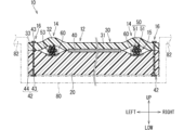
- FIG. 2 is a sectional view taken along line II-II in FIG.
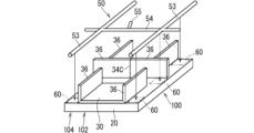
- FIG. 3 is a perspective view showing a method of manufacturing a floor wiring module.
- FIG. 4 is a perspective view showing a method of manufacturing a floor wiring module.
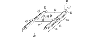
- FIG. 5 is a perspective view showing a method of manufacturing a floor wiring module.
- the floor wiring module of the present disclosure is as follows.
- the silencer and the carpet are fixed by heat pressing in the first region, they can be fixed with a relatively high fixing force.
- the silencer and the carpet can be easily maintained in an integrated state, so that the silencer and the carpet can be easily arranged on the floor panel.
- the second area next to the first area is the area where the wiring members are placed, the wiring members can be easily placed on the stacked structure of the silencer and the carpet, and the heating press in the first area does not affect the wiring members. Hateful.
- the laminated region is located next to the second region on the one principal surface, and the silencer and the carpet are connected to each other via a mechanical bonding member. It may also include a third region that is fixed. Thereby, the third region can be easily provided. Further, the first region, the second region, and the third region can be provided in this order, so that the wiring member is less likely to be affected by the hot press in the first region.
- the area occupied by the first region on the one main surface may be larger than the area occupied by the third region. This makes it easier to maintain the silencer and the carpet in an integrated state.
- the first area may be arranged in an area of the vehicle floor that is more likely to be stepped on by an occupant than the second area and the third area. good.
- the wiring member in the second region and the mechanical joint member in the third region are less likely to be stepped on by the occupant.
- the silencer and the carpet are fixed in the first region by a heating press, it is easy to obtain strength against being stepped on by an occupant.
- the second area is provided with a wiring holding part that fixes the wiring member to at least one of the silencer and the carpet. You can leave it there. This suppresses misalignment between the wiring member and the laminate of the silencer and the carpet.
- the wiring holding section is a holding section having a mechanical joining member, or has an adhesion force weaker than the adhesion force between the silencer and the carpet in the first region. It may also be an adhesive holding part having a. This makes it easy to remove the wiring member even if it is necessary to remove the wiring member from the silencer and carpet stack during repair of the floor wiring module.
- the carpet has a window portion located in an area inside the outer edge of the one main surface of the silencer, and the wiring member may have an end extending through the window and onto the carpet. Thereby, the wiring member can be easily connected to a device located in a region inside the outer edge on one main surface of the silencer.
- the floor laminate of the present disclosure includes a silencer and a carpet laminated on one main surface of the silencer, and a laminated area of the silencer and the carpet is formed between the silencer and the carpet.
- a laminate for a floor comprising: a fixing area where is heat-pressed and fixing; and a separation area located next to the fixing area on the one main surface and separating the silencer and the carpet. It is.
- the silencer and the carpet are fixed by hot pressing in the fixing region, so that they can be fixed with a relatively high fixing force.
- the silencer and the carpet can be easily maintained in an integrated state, so that the silencer and the carpet can be easily arranged on the floor panel.
- the silencer and the carpet are separated in a separation area different from the fixed area, it is easy to arrange the wiring member between the silencer and the carpet.
- the method for manufacturing a floor wiring module of the present disclosure includes a step of hot pressing and fixing a part of the laminated area of the silencer and the carpet, and a step of fixing the part of the laminated area of the silencer and the carpet, and fixing the part of the laminated area of the silencer and the carpet. and a step of arranging a wiring member between the silencer and the carpet in a portion where the carpet is not fixed.
- the silencer and the carpet are fixed by hot pressing in a part of the laminated region, so that they can be fixed with a relatively high fixing force.
- the silencer and the carpet can be easily maintained in an integrated state, so that the silencer and the carpet can be easily arranged on the floor panel.
- the wiring member is arranged in a region different from the region where the silencer and the carpet are heated and fixed, the wiring member is hardly affected by the heat press for fixing the silencer and the carpet.
- FIG. 1 is a plan view showing a floor wiring module 10 according to the first embodiment.
- FIG. 2 is a sectional view taken along line II-II in FIG.
- the front-rear direction (FRONT, REAR), left-right direction (LEFT, RIGHT), and up-down direction (UP, LOW) shown in FIGS. 1 and 2 correspond to the front-rear direction, left-right direction, and up-down direction of the vehicle.
- the floor wiring module 10 is placed on the floor panel 80 of the vehicle.
- the floor panel 80 is arranged at the lower part of the vehicle compartment.
- the floor panel 80 is, for example, a metal floorboard.
- the floor wiring module 10 includes a silencer 20, a carpet 30, and a wiring member 50.
- the silencer 20 is a soundproofing member placed on the floor panel 80.
- the silencer 20 may be a member that flattens unevenness of the floor panel 80 or the like.
- the silencer 20 is, for example, a molded body made of fiber, foamed resin, or the like. Silencer 20 may be thicker than carpet 30.
- the silencer 20 has higher rigidity than the carpet 30, and may be able to maintain its shape.
- the carpet 30 is placed on the silencer 20.
- the carpet 30 is normally exposed as a decorative surface inside the vehicle interior.
- the carpet 30 may have lower rigidity than the silencer 20 and may be easier to bend.
- the carpet 30 is laminated on one main surface of the silencer 20.
- the wiring member 50 is held between the silencer 20 and the carpet 30.
- the carpet 30 is divided in the longitudinal direction of the vehicle.
- the wiring member 50 connects devices in a vehicle.
- the wiring member 50 includes a plurality of linear transmission members 51.
- the linear transmission member 51 may be an electric wire that transmits electricity or an optical fiber cable that transmits light.
- the plurality of linear transmission members 51 may be grouped together according to their respective routes in the vehicle.
- the plurality of linear transmission members 51 may be bound together with a binding member such as an adhesive tape or a binding band.
- a connector 52 is provided at the end of the linear transmission member 51.
- the linear transmission member 51 is connected to a device or another wiring member 50 via a connector 52.
- the connector 52 includes, for example, a connector 52 terminal and a connector 52 housing.
- An end of the linear transmission member 51 is connected to a connector 52 terminal.
- the connector 52 terminals are positioned and held in the connector 52 housing.
- the end of the linear transmission member 51 may be directly connected to a device or the like without using the connector 52.
- the wiring member 50 has a first extending portion 53, a second extending portion 54, and a third extending portion 55.
- the first extending portion 53 extends along the longitudinal direction of the vehicle.
- a pair of first extending portions 53 are provided.
- the pair of first extending portions 53 are spaced apart from each other in the width direction of the vehicle.
- One of the pair of first extending portions 53 extends along the left side edge of the silencer 20, and the other of the pair of first extending portions 53 extends along the right side edge of the silencer 20.
- the front end portion of the first extending portion 53 extends from the front end of the silencer 20 toward the front of the vehicle than the silencer 20 .
- the rear end portion of the first extending portion 53 extends from the rear end of the silencer 20 toward the rear of the vehicle than the silencer 20 .
- the second extending portion 54 extends along the width direction of the vehicle.
- the second extending portion 54 is arranged at an intermediate portion of the silencer 20 along the extending direction of the first extending portion 53.
- a junction portion of the first extending portion 53 and the second extending portion 54 is a branch portion 56 .
- the left end portion of the second extending portion 54 extends from the left end of the silencer 20 to the left side of the vehicle than the silencer 20.
- the right end portion of the second extending portion 54 extends from the right end of the silencer 20 to the right side of the vehicle than the silencer 20.
- the third extending portion 55 branches from the middle portion along the extending direction of the second extending portion 54.
- a branching portion 56 between the second extending portion 54 and the third extending portion 55 is provided between the pair of first extending portions 53 .
- the laminated region of the silencer 20 and the carpet 30 includes a first region 12, a second region 14, and a third region 16.
- the first region 12 is a region where the silencer 20 and the carpet 30 are fixed by heat pressing.
- a thermal adhesive 40 is provided between the silencer 20 and the carpet 30. The silencer 20 and the carpet 30 are firmly fixed via the thermal adhesive 40.
- the second region 14 is located next to the first region 12 on one main surface of the silencer 20.
- the two-dot chain line in FIG. 1 indicates the boundary between the first region 12 and the second region 14.
- the second region 14 is a region where the wiring member 50 is located between the silencer 20 and the carpet 30. Since the wiring member 50 is located between the silencer 20 and the carpet 30 in the second region 14, at least one of the silencer 20 and the carpet 30 may be bent or bent by the thickness of the wiring member 50. . In the example shown in FIG. 2, the silencer 20 is bent and the carpet 30 is bent. The carpet 30 may be prevented from bending, for example, by providing a groove in the silencer 20.
- the second region 14 is provided with a wiring holding portion 15 that fixes the wiring member 50 to at least one of the silencer 20 and the carpet 30.
- the wiring holding section 15 is a holding section having a mechanical joining member, or an adhesive holding section having an adhesion force that is weaker than the adhesion force between the silencer 20 and the carpet 30 in the first region 12 .
- the mechanical joining member may be an elastic member such as a sponge. Frictional force is generated by compressing the elastic member between the wiring member 50 and the silencer 20 or the carpet 30, and the wiring member 50 is held by the frictional force.
- the adhesion holding part 15 is an adhesive holding part having a weaker adhesion force than the adhesion force between the silencer 20 and the carpet 30 in the first region 12, the adhesion holding part is a one-sided adhesive tape, a double-sided adhesive tape, an adhesive, etc.
- the portion may be bonded using an adhesive member.
- the adhesive holding portion may be a portion where the resin of at least one of the wiring member 50 and the silencer 20 or the carpet 30 is melted and adhered to the other member without using other members, such as by fusion bonding. good.
- FIG. 2 an example of an adhesive holding part having an adhesive member 60 such as double-sided adhesive tape or adhesive is shown as the wiring holding part 15.
- the wiring holding parts 15 may be provided at multiple locations spaced apart along the extending direction of the wiring member 50 placed on the silencer 20.
- the wiring holding portion 15 is preferably provided at a portion where the wiring member 50 extends from the silencer 20, a branch portion 56 of the wiring member 50, or the like.
- the wiring holding portion 15 may be provided over the entire wiring member 50 placed on the silencer 20 along the extending direction.
- the third region 16 is located next to the second region 14 on one main surface of the silencer 20.
- the third region 16 is a region where the silencer 20 and the carpet 30 are fixed via a mechanical joining member 42.
- the mechanical joining member 42 is not particularly limited, and may be, for example, a tag pin-like member, a stapler, a sewing thread, or the like.
- Third region 16 includes the outer edge of carpet 30.
- the third region 16 is connected to the first region 12 via the second region 14.
- the second region 14 is interposed between the first region 12 and the third region 16.
- the second region 14 and the third region 16 are free ends before the third region 16 is fixed.
- FIG. 2 an example of a tag pin-like member 42 is shown as the mechanical joining member 42.
- the tag pin-like member 42 includes, for example, a pair of support pieces 43 and a connection piece 44 that connects the pair of support pieces 43.
- One of the pair of support pieces 43 is located below the lower surface of the silencer 20 and hooked to the lower surface of the silencer 20.
- the other of the pair of support pieces 43 is located above the upper surface of the carpet 30 and hooked onto the upper surface of the carpet 30.
- the connecting piece 44 passes through the silencer 20 and the carpet 30.
- the area occupied by the first region 12 on one main surface of the silencer 20 is larger than the area occupied by the third region 16.
- the area occupied by the first region 12 may be larger than the area occupied by the second region 14.
- the area occupied by the first region 12 may be larger than the sum of the area occupied by the second region 14 and the area occupied by the third region 16.
- the first region 12 may occupy more than half of the area of one main surface of the silencer 20 .
- the first region 12 is arranged on the floor of the vehicle in an area that is more easily stepped on by the occupant than the second region 14 and the third region 16.
- the area that is likely to be stepped on by the occupant is, for example, the area under the occupant's feet. Areas that are unlikely to be stepped on by occupants include, for example, under the seat and on the sides of the locker 82.
- the part forming the first area 12 is defined as a first fixed part 31
- the part forming the second area 14 is defined as a wiring cover part 32
- the part forming the third area 16 is defined as a second fixed part 33.
- Wire cover portions 32 are connected to the left, right, and rear of the first fixed portion 31 of the carpet 30 located at the front of the vehicle.
- the left wiring covering portion 32 and the rear wiring covering portion 32 are separated via a slit 34A.
- the right wiring covering portion 32 and the rear wiring covering portion 32 are separated via a slit 34B.
- the rear wiring cover portion 32 is separated into left and right portions via a slit 34C.
- tag pin-like members 42 are provided at four locations around the branch portion 56.
- Wire cover portions 32 are connected to the left and right sides of a first fixed portion 31 of the carpet 30 located at the rear of the vehicle.
- the carpet 30 has a window portion 35 located in an area inside the outer edge of one main surface of the silencer 20.
- the wiring member 50 has an end portion extending onto the carpet 30 through the window portion 35.
- the end of the third extension portion 55 extends out onto the carpet 30 through the window portion 35.
- the end of the third extension portion 55 is connected to equipment on the carpet 30. Such equipment may be equipment placed in the seat.
- FIGS. 3 to 5 are perspective views showing a method of manufacturing the floor wiring module 10.
- a part of the laminated region of the silencer 20 and the carpet 30 is fixed by hot pressing.
- the carpet 30 is divided into two along the front-rear direction. Further, a slit 34 is formed in the front carpet 30.
- the area of the carpet 30 that is heated and pressed is the area surrounded by the two-dot chain line.
- the front carpet 30 and the rear carpet 30 are separated from each other in the front-rear direction. The front carpet 30 and the rear carpet 30 may be in contact with each other in the front-rear direction.
- the heating press is performed using a heating press device 90.
- the hot press device 90 includes a pair of press members 91 and 92.
- the press member 91 presses the carpet 30, and the press member 92 presses the silencer 20.
- hot pressing is performed in a state where at least one of the pair of press members 91 and 92 is heated by a heating device.
- a thermal adhesive 40 is provided on the portion of the silencer 20 and the carpet 30 that is desired to be fixed.
- the silencer 20 and the carpet 30 are fixed to each other via the thermal adhesive 40 by heating and pressing the portion where the thermal adhesive 40 is provided.
- the portions of the silencer 20 and the carpet 30 where the thermal adhesive 40 is not provided may also be heated and pressed. In this case, the portions of the silencer 20 and the carpet 30 on which the thermal adhesive 40 is not provided do not need to be fixed when heated and pressed.
- the wiring member 50 is placed between the silencer 20 and the carpet 30 in another part of the laminated region of the silencer 20 and the carpet 30, where the silencer 20 and the carpet 30 are not fixed.
- the floor laminate 100 includes a silencer 20 and a carpet 30 laminated on one main surface of the silencer 20.
- the laminated region of the silencer 20 and the carpet 30 includes a fixed region 102 and a separation region 104.
- the fixed area 102 is an area where the silencer 20 and the carpet 30 are heated and pressed and fixed.
- the fixed area 102 corresponds to the first area 12 in the floor wiring module 10.
- Separation region 104 is located next to fixed region 102 on one main surface of silencer 20 .
- Separation area 104 is an area where silencer 20 and carpet 30 are separated.
- the separation region 104 is a portion that becomes the second region 14 and the third region 16 in the floor wiring module 10.
- a movable piece 36 whose distal end can move more freely around the proximal end than the proximal end connected to the fixing region 102 in the part forming the separation region 104. It is said that The movable piece 36 can be bent with its base end connected to the fixed region 102 being a fold.
- four movable pieces 36 are provided on the left, right, left rear, and right rear with respect to the fixed area 102.
- movable pieces 36 are provided on the right and left sides of the fixed area 102, respectively.
- the wiring member 50 is arranged between the silencer 20 and the carpet 30.
- the floating piece 36 is bent to expose the upper surface of the silencer 20. Then, the wiring member 50 is placed on the exposed upper surface of the silencer 20. At this time, the upper surface of the silencer 20 exposed by bending all the movable pieces 36 has a shape corresponding to the route of the wiring member 50. Therefore, by arranging the wiring member 50 on the exposed upper surface of the silencer 20, the wiring member 50 can be easily arranged along a predetermined route.
- the floating piece 36 is bent at 90 degrees.
- the floating piece 36 may be bent 180 degrees so that the floating piece 36 overlaps the fixed region 102.
- the carpet 30 may be formed so that the movable piece 36 can be bent so that the movable piece 36 overlaps the fixed area 102.
- an adhesive member 60 such as double-sided adhesive tape or adhesive is provided on the top surface of the silencer 20.
- the wiring member 50 is arranged on the upper surface of the silencer 20, and the adhesive member 60 is bonded to the silencer 20 and the wiring member 50, thereby forming the wiring holding portion 15.
- the floating piece 36 located behind the fixed area 102 may or may not be in contact with the rear carpet 30 of the two carpets 30.
- the ends of the first extending portion 53 and the second extending portion 54 are pulled out to the outside of the silencer 20.
- the third extending portion 55 is pulled out onto the carpet 30 from between the two floating pieces 36 separated from each other by the slit 34C.
- the space between the two floating pieces 36 is the window portion 35 .
- the wiring member 50 is placed between the silencer 20 and the carpet 30, resulting in the state shown in FIG. 5.
- the window portion 35 only needs to be able to draw out a portion of the wiring member 50.
- the window portion 35 may be shaped like a slit by having the front portions and the rear portions of the two floating pieces 36 contact each other in the left-right direction relative to the wiring member 50.
- the window portion 35 may have an open shape by separating the two movable pieces 36 from each other in the left-right direction.
- FIG. 5 shows an example of fixing the silencer 20 and the carpet 30 by driving the tag pin-like member 42 using a jig 94.
- a tag pin-like member 42 is fixed to the tip of the movable piece 36 on the opposite side from the fixed area 102.
- the floor wiring module 10 is manufactured by fixing the silencer 20 and the carpet 30 via the tag pin-like member 42 at a predetermined location in the laminated region.
- the silencer 20 and the carpet 30 are fixed by heat pressing in the first region 12, so that they can be fixed with a relatively high fixing force.
- the silencer 20 and the carpet 30 can be easily maintained in an integrated state, so that the silencer 20 and the carpet 30 can be easily arranged on the floor panel 80.
- the wiring member 50 can be easily arranged on the stack of the silencer 20 and the carpet 30, and the heating press in the first region 12 The wiring member 50 is less likely to be affected by this.
- the laminated region includes a third region 16 located next to the second region 14 on one main surface of the silencer 20 and to which the silencer 20 and the carpet 30 are fixed via a mechanical bonding member 42. include.
- the third region 16 can be easily provided.
- the first region 12, the second region 14, and the third region 16 can be provided in this order, so that the wiring member 50 is less affected by the hot press in the first region 12.
- the area occupied by the first region 12 on one main surface of the silencer 20 is larger than the area occupied by the third region 16.
- the first area 12 is arranged in an area on the floor of the vehicle that is more likely to be stepped on by the occupant than the second area 14 and the third area 16.
- the wiring member 50 in the second region 14 and the mechanical joint member 42 in the third region 16 are less likely to be stepped on by the occupant.
- the silencer 20 and the carpet 30 are fixed in the first region 12 by heating press, it is easy to obtain strength against stepping on the carpet by an occupant.
- a wiring holding portion 15 is provided that fixes the wiring member 50 to at least one of the silencer 20 and the carpet 30. This suppresses misalignment between the wiring member 50 and the laminate of the silencer 20 and the carpet 30.
- the wiring holding section 15 is a holding section via a mechanical joining member, or an adhesive holding section having a weaker adhesion force than the adhesion force between the silencer 20 and the carpet 30 in the first region 12.
- the carpet 30 has a window portion 35 located in an area inside the outer edge of one main surface of the silencer 20, and the wiring member 50 has an end portion extending onto the carpet 30 through the window portion 35.
- the wiring member 50 can be easily connected to a device located in an area inside the outer edge of one main surface of the silencer 20.
- the silencer 20 and the carpet 30 are fixed by hot pressing in the fixing region 102, so that they can be fixed with a relatively high fixing force.
- the silencer 20 and the carpet 30 can be easily maintained in an integrated state, so that the silencer 20 and the carpet 30 can be easily arranged on the floor panel 80.
- the wiring member 50 can be easily placed between the silencer 20 and the carpet 30.
- the silencer 20 and the carpet 30 are fixed by hot pressing in a part of the laminated region, so that they can be fixed with a relatively high fixing force.
- the silencer 20 and the carpet 30 can be easily maintained in an integrated state, so that the silencer 20 and the carpet 30 can be easily arranged on the floor panel 80.
- the wiring member 50 is arranged in a region different from the region where the silencer 20 and the carpet 30 are fixed by heat pressing, the influence of the heat press for fixing the silencer 20 and the carpet 30 is on the wiring member 50. It is difficult to reach.
- the lamination region has been described so far as including the third region 16, this is not an essential configuration.
- the stacked region does not need to include the third region 16.
- the loose piece 36 of the carpet 30 may remain unsecured in the vehicle.
- the movable piece 36 of the carpet 30 may be fixed to a member other than the silencer 20 in the vehicle, and the state in which the wiring member 50 is sandwiched between the silencer 20 and the carpet 30 may be maintained.
- the wiring holding portion 15 is provided in the second region 14, this is not an essential configuration.
- the wiring holding portion 15 may not be provided in the second region 14.
- the wiring member 50 has been described as having an end portion extending onto the carpet 30 through the window portion 35, this is not an essential configuration.
- the wiring member 50 does not need to have the third extending portion 55.
- the window portion 35 does not need to be the slit 34, and may be a hole penetrating the carpet 30.
- the carpet 30 is divided into a plurality of parts and the silencer 20 has a size corresponding to the combined size of the plurality of divided parts of the carpet 30, this is not an essential configuration. isn't it.
- the silencer may be divided into a plurality of parts, and the carpet may have a size corresponding to the combined size of the plurality of silencer divisions.
Landscapes
- Engineering & Computer Science (AREA)
- Mechanical Engineering (AREA)
- Details Of Indoor Wiring (AREA)
- Installation Of Indoor Wiring (AREA)
- Vehicle Interior And Exterior Ornaments, Soundproofing, And Insulation (AREA)
- Architecture (AREA)
- Civil Engineering (AREA)
- Structural Engineering (AREA)
- Central Heating Systems (AREA)
- Passenger Equipment (AREA)
Abstract
Description
最初に本開示の実施態様を列記して説明する。
本開示のフロア用配線モジュール、フロア用積層体及びフロア用配線モジュールの製造方法の具体例を、以下に図面を参照しつつ説明する。なお、本開示はこれらの例示に限定されるものではなく、請求の範囲によって示され、請求の範囲と均等の意味及び範囲内でのすべての変更が含まれることが意図される。
以下、実施形態1にかかるフロア用配線モジュール10、フロア用積層体100及びフロア用配線モジュール10の製造方法について説明する。図1は実施形態1にかかるフロア用配線モジュール10を示す平面図である。図2は図1のII-II線に沿った断面図である。図1及び図2に示される前後方向(FRONT,REAR)、左右方向(LEFT,RIGHT)、及び上下方向(UP,LOW)は、車両における前後方向、左右方向、及び上下方向に対応する。
次に、図3から図5を参照しつつ、フロア用配線モジュール10の製造方法について説明する。図3から図5はフロア用配線モジュール10の製造方法を示す斜視図である。
以上のように構成されたフロア用配線モジュール10によると、サイレンサ20とカーペット30とが第1領域12において加熱プレスされて固定されているため、比較的高い固着力によって固着されることができる。これにより、フロア用配線モジュール10において、サイレンサ20及びカーペット30が一体化された状態に保たれやすいため、サイレンサ20及びカーペット30をフロアパネル80に簡易に配置できる。また、第1領域12の隣の第2領域14が配線部材50の配置領域であるため、サイレンサ20及びカーペット30の積層体に配線部材50を簡易に配置できると共に、第1領域12における加熱プレスの影響が配線部材50に及びにくい。
これまで、積層領域が第3領域16を含むものとして説明されたが、このことは必須の構成ではない。積層領域は第3領域16を含んでいなくてもよい。例えば、カーペット30の遊動片36が車両において固定されないままであってもよい。また例えば、カーペット30の遊動片36が車両においてサイレンサ20以外の部材に固定されて、サイレンサ20とカーペット30とが配線部材50を挟んだ状態が保持されてもよい。
12 第1領域
14 第2領域
15 配線保持部
16 第3領域
20 サイレンサ
30 カーペット
31 第1固着部分
32 配線覆い部分
33 第2固着部分
34、34A、34B、34C スリット
35 窓部
36 遊動片
40 熱粘着剤
42 タグピン状部材(機械的接合部材)
43 支持片
44 連結片
50 配線部材
51 線状伝送部材
52 コネクタ
53 第1延在部分
54 第2延在部分
55 第3延在部分
56 分岐部
60 接着部材
80 フロアパネル
82 ロッカ
90 加熱プレス装置
91、92 プレス部材
100 フロア用積層体
102 固定領域
104 分離領域
Claims (9)
- サイレンサと、
前記サイレンサの一方主面に積層されたカーペットと、
前記サイレンサと前記カーペットとの間に挟まれて保持されている配線部材と、
を備え、
前記サイレンサと前記カーペットとの積層領域は、前記サイレンサと前記カーペットとが加熱プレスされて固定された第1領域と、前記一方主面上において前記第1領域の隣に位置し、かつ、前記サイレンサと前記カーペットとの間に前記配線部材が位置する第2領域とを含む、フロア用配線モジュール。 - 請求項1に記載のフロア用配線モジュールであって、
前記積層領域は、前記一方主面上において前記第2領域の隣に位置し、かつ、前記サイレンサと前記カーペットとが機械的接合部材を介して固定されている第3領域を含む、フロア用配線モジュール。 - 請求項2に記載のフロア用配線モジュールであって、
前記一方主面において前記第1領域が占める面積は、前記第3領域が占める面積よりも大きい、フロア用配線モジュール。 - 請求項2又は請求項3に記載のフロア用配線モジュールであって、
前記第1領域は、車両のフロアにおいて、前記第2領域及び前記第3領域よりも乗員によって踏まれやすい領域に配置される、フロア用配線モジュール。 - 請求項1から請求項3のいずれか1項に記載のフロア用配線モジュールであって、
前記第2領域には、前記配線部材を前記サイレンサと前記カーペットとの少なくとも一方に固定する配線保持部が設けられている、フロア用配線モジュール。 - 請求項5に記載のフロア用配線モジュールであって、
前記配線保持部は、機械的接合部材を有する保持部、又は、前記第1領域における前記サイレンサと前記カーペットとの固着力よりも弱い固着力を有する接着保持部である、フロア用配線モジュール。 - 請求項1から請求項3のいずれか1項に記載のフロア用配線モジュールであって、
前記カーペットは、前記サイレンサの前記一方主面における外縁よりも内側領域に位置する窓部を有し、
前記配線部材は、前記窓部を通じて前記カーペット上に延び出る端部を有する、フロア用配線モジュール。 - サイレンサと、
前記サイレンサの一方主面に積層されたカーペットと、
を備え、
前記サイレンサと前記カーペットとの積層領域は、前記サイレンサと前記カーペットとが加熱プレスされて固定された固定領域と、前記一方主面上において前記固定領域の隣に位置し、かつ、前記サイレンサと前記カーペットとが分離している分離領域とを含む、フロア用積層体。 - サイレンサとカーペットとの積層領域の一部を加熱プレスして固定する工程と、
前記積層領域の他の一部であって前記サイレンサと前記カーペットとが固定されていない部分において、前記サイレンサと前記カーペットとの間に配線部材を配置する工程と、
を備える、フロア用配線モジュールの製造方法。
Priority Applications (2)
| Application Number | Priority Date | Filing Date | Title |
|---|---|---|---|
| CN202380033550.0A CN118946483A (zh) | 2022-04-25 | 2023-04-17 | 地板用配线模块、地板用层叠体及地板用配线模块的制造方法 |
| US18/857,261 US20250269806A1 (en) | 2022-04-25 | 2023-04-17 | Floor wiring module, floor stacked body, and method of manufacturing floor wiring module |
Applications Claiming Priority (2)
| Application Number | Priority Date | Filing Date | Title |
|---|---|---|---|
| JP2022071467A JP7722250B2 (ja) | 2022-04-25 | 2022-04-25 | フロア用配線モジュール、フロア用積層体及びフロア用配線モジュールの製造方法 |
| JP2022-071467 | 2022-04-25 |
Publications (1)
| Publication Number | Publication Date |
|---|---|
| WO2023210431A1 true WO2023210431A1 (ja) | 2023-11-02 |
Family
ID=88518667
Family Applications (1)
| Application Number | Title | Priority Date | Filing Date |
|---|---|---|---|
| PCT/JP2023/015375 Ceased WO2023210431A1 (ja) | 2022-04-25 | 2023-04-17 | フロア用配線モジュール、フロア用積層体及びフロア用配線モジュールの製造方法 |
Country Status (4)
| Country | Link |
|---|---|
| US (1) | US20250269806A1 (ja) |
| JP (2) | JP7722250B2 (ja) |
| CN (1) | CN118946483A (ja) |
| WO (1) | WO2023210431A1 (ja) |
Citations (10)
| Publication number | Priority date | Publication date | Assignee | Title |
|---|---|---|---|---|
| JPS63166635A (ja) * | 1986-12-27 | 1988-07-09 | Honda Motor Co Ltd | 車輌用電装部品の組付方法 |
| JP2007302128A (ja) * | 2006-05-12 | 2007-11-22 | Kotobukiya Fronte Co Ltd | 成形カーペット、車両用成形カーペットモジュール体、車両用成形カーペットモジュール体の製造方法 |
| JP2012123974A (ja) * | 2010-12-07 | 2012-06-28 | Sumitomo Wiring Syst Ltd | ワイヤハーネス |
| WO2014038242A1 (ja) * | 2012-09-10 | 2014-03-13 | 住友電装株式会社 | ワイヤハーネス |
| WO2014050196A1 (ja) * | 2012-09-26 | 2014-04-03 | 住友電装株式会社 | ワイヤーハーネス |
| JP2014068521A (ja) * | 2012-09-10 | 2014-04-17 | Sumitomo Wiring Syst Ltd | ワイヤーハーネス |
| WO2015037414A1 (ja) * | 2013-09-12 | 2015-03-19 | 住友電装株式会社 | ワイヤーハーネス |
| JP2015220800A (ja) * | 2014-05-15 | 2015-12-07 | 住友電装株式会社 | 防音部材付電線モジュール |
| WO2016052150A1 (ja) * | 2014-10-03 | 2016-04-07 | 株式会社オートネットワーク技術研究所 | 吸音材付きワイヤーハーネス |
| JP2016107869A (ja) * | 2014-12-08 | 2016-06-20 | 矢崎総業株式会社 | カーペットモジュール |
Family Cites Families (3)
| Publication number | Priority date | Publication date | Assignee | Title |
|---|---|---|---|---|
| JP5900314B2 (ja) * | 2012-12-20 | 2016-04-06 | 住友電装株式会社 | ワイヤハーネス |
| JP6992430B2 (ja) * | 2017-11-17 | 2022-01-13 | 株式会社オートネットワーク技術研究所 | ワイヤーハーネスの配設構造 |
| DE112019008042B4 (de) * | 2018-03-27 | 2024-08-14 | Autonetworks Technologies, Ltd. | Kabelbaum |
-
2022
- 2022-04-25 JP JP2022071467A patent/JP7722250B2/ja active Active
-
2023
- 2023-04-17 CN CN202380033550.0A patent/CN118946483A/zh active Pending
- 2023-04-17 WO PCT/JP2023/015375 patent/WO2023210431A1/ja not_active Ceased
- 2023-04-17 US US18/857,261 patent/US20250269806A1/en active Pending
-
2025
- 2025-04-03 JP JP2025061866A patent/JP2025104358A/ja active Pending
Patent Citations (10)
| Publication number | Priority date | Publication date | Assignee | Title |
|---|---|---|---|---|
| JPS63166635A (ja) * | 1986-12-27 | 1988-07-09 | Honda Motor Co Ltd | 車輌用電装部品の組付方法 |
| JP2007302128A (ja) * | 2006-05-12 | 2007-11-22 | Kotobukiya Fronte Co Ltd | 成形カーペット、車両用成形カーペットモジュール体、車両用成形カーペットモジュール体の製造方法 |
| JP2012123974A (ja) * | 2010-12-07 | 2012-06-28 | Sumitomo Wiring Syst Ltd | ワイヤハーネス |
| WO2014038242A1 (ja) * | 2012-09-10 | 2014-03-13 | 住友電装株式会社 | ワイヤハーネス |
| JP2014068521A (ja) * | 2012-09-10 | 2014-04-17 | Sumitomo Wiring Syst Ltd | ワイヤーハーネス |
| WO2014050196A1 (ja) * | 2012-09-26 | 2014-04-03 | 住友電装株式会社 | ワイヤーハーネス |
| WO2015037414A1 (ja) * | 2013-09-12 | 2015-03-19 | 住友電装株式会社 | ワイヤーハーネス |
| JP2015220800A (ja) * | 2014-05-15 | 2015-12-07 | 住友電装株式会社 | 防音部材付電線モジュール |
| WO2016052150A1 (ja) * | 2014-10-03 | 2016-04-07 | 株式会社オートネットワーク技術研究所 | 吸音材付きワイヤーハーネス |
| JP2016107869A (ja) * | 2014-12-08 | 2016-06-20 | 矢崎総業株式会社 | カーペットモジュール |
Also Published As
| Publication number | Publication date |
|---|---|
| CN118946483A (zh) | 2024-11-12 |
| JP2023161234A (ja) | 2023-11-07 |
| JP7722250B2 (ja) | 2025-08-13 |
| JP2025104358A (ja) | 2025-07-09 |
| US20250269806A1 (en) | 2025-08-28 |
Similar Documents
| Publication | Publication Date | Title |
|---|---|---|
| JP5894386B2 (ja) | クランプ付ワイヤーハーネス | |
| JP3715192B2 (ja) | 車両シート用ワイヤハーネス | |
| CN107005038A (zh) | 线束 | |
| JPH11178174A (ja) | 電線保持具 | |
| US20240262302A1 (en) | Wire harness and wire harness with base member | |
| JP6984180B2 (ja) | 配線モジュールの敷設構造及び配線モジュール | |
| JPWO2020121463A1 (ja) | ワイヤハーネス及びワイヤハーネスの製造方法 | |
| JP2014186800A (ja) | ワイヤーハーネス用外装シートの取付け方法 | |
| WO2023210431A1 (ja) | フロア用配線モジュール、フロア用積層体及びフロア用配線モジュールの製造方法 | |
| JP4353927B2 (ja) | フラットケーブル結束ホルダー | |
| JP7800638B2 (ja) | 配線部材 | |
| WO2023276609A1 (ja) | 配線部材 | |
| WO2019225029A1 (ja) | 配線部材の固定構造 | |
| JP7160059B2 (ja) | 配線部材の固定構造 | |
| JP2002264710A (ja) | 車両シート用ワイヤハーネス | |
| JP6992855B2 (ja) | 配線モジュール | |
| JP7375726B2 (ja) | ドア用配線モジュール及び複合サービスホールカバー | |
| CN117836873A (zh) | 带配线构件的被粘物 | |
| JP7768108B2 (ja) | ワイヤハーネスの配索構造及びワイヤハーネス | |
| JP2023066058A (ja) | 配線部材付き被着体及び配線部材付き被着体の製造方法 | |
| CN116761865B (zh) | 熔接片及布线构件 | |
| JP2003111239A (ja) | ジョイントボックス | |
| JP2013187970A (ja) | ワイヤハーネス及び配線具 | |
| JP2002154391A (ja) | 車両用配線装置 | |
| JP2010252424A (ja) | ワイヤハーネス |
Legal Events
| Date | Code | Title | Description |
|---|---|---|---|
| 121 | Ep: the epo has been informed by wipo that ep was designated in this application |
Ref document number: 23796174 Country of ref document: EP Kind code of ref document: A1 |
|
| WWE | Wipo information: entry into national phase |
Ref document number: 202380033550.0 Country of ref document: CN |
|
| NENP | Non-entry into the national phase |
Ref country code: DE |
|
| 122 | Ep: pct application non-entry in european phase |
Ref document number: 23796174 Country of ref document: EP Kind code of ref document: A1 |
|
| WWP | Wipo information: published in national office |
Ref document number: 18857261 Country of ref document: US |