WO2023204017A1 - 基板処理装置、および基板処理方法 - Google Patents
基板処理装置、および基板処理方法 Download PDFInfo
- Publication number
- WO2023204017A1 WO2023204017A1 PCT/JP2023/013963 JP2023013963W WO2023204017A1 WO 2023204017 A1 WO2023204017 A1 WO 2023204017A1 JP 2023013963 W JP2023013963 W JP 2023013963W WO 2023204017 A1 WO2023204017 A1 WO 2023204017A1
- Authority
- WO
- WIPO (PCT)
- Prior art keywords
- substrate
- nozzle
- film
- processing liquid
- liquid
- Prior art date
- Legal status (The legal status is an assumption and is not a legal conclusion. Google has not performed a legal analysis and makes no representation as to the accuracy of the status listed.)
- Ceased
Links
Images





Classifications
-
- H—ELECTRICITY
- H10—SEMICONDUCTOR DEVICES; ELECTRIC SOLID-STATE DEVICES NOT OTHERWISE PROVIDED FOR
- H10P—GENERIC PROCESSES OR APPARATUS FOR THE MANUFACTURE OR TREATMENT OF DEVICES COVERED BY CLASS H10
- H10P70/00—Cleaning of wafers, substrates or parts of devices
- H10P70/50—Cleaning of wafers, substrates or parts of devices characterised by the part to be cleaned
- H10P70/54—Cleaning of wafer edges
-
- H—ELECTRICITY
- H10—SEMICONDUCTOR DEVICES; ELECTRIC SOLID-STATE DEVICES NOT OTHERWISE PROVIDED FOR
- H10P—GENERIC PROCESSES OR APPARATUS FOR THE MANUFACTURE OR TREATMENT OF DEVICES COVERED BY CLASS H10
- H10P50/00—Etching of wafers, substrates or parts of devices
-
- H—ELECTRICITY
- H10—SEMICONDUCTOR DEVICES; ELECTRIC SOLID-STATE DEVICES NOT OTHERWISE PROVIDED FOR
- H10P—GENERIC PROCESSES OR APPARATUS FOR THE MANUFACTURE OR TREATMENT OF DEVICES COVERED BY CLASS H10
- H10P50/00—Etching of wafers, substrates or parts of devices
- H10P50/20—Dry etching; Plasma etching; Reactive-ion etching
- H10P50/28—Dry etching; Plasma etching; Reactive-ion etching of insulating materials
- H10P50/282—Dry etching; Plasma etching; Reactive-ion etching of insulating materials of inorganic materials
- H10P50/283—Dry etching; Plasma etching; Reactive-ion etching of insulating materials of inorganic materials by chemical means
-
- H—ELECTRICITY
- H10—SEMICONDUCTOR DEVICES; ELECTRIC SOLID-STATE DEVICES NOT OTHERWISE PROVIDED FOR
- H10P—GENERIC PROCESSES OR APPARATUS FOR THE MANUFACTURE OR TREATMENT OF DEVICES COVERED BY CLASS H10
- H10P52/00—Grinding, lapping or polishing of wafers, substrates or parts of devices
-
- H—ELECTRICITY
- H10—SEMICONDUCTOR DEVICES; ELECTRIC SOLID-STATE DEVICES NOT OTHERWISE PROVIDED FOR
- H10P—GENERIC PROCESSES OR APPARATUS FOR THE MANUFACTURE OR TREATMENT OF DEVICES COVERED BY CLASS H10
- H10P72/00—Handling or holding of wafers, substrates or devices during manufacture or treatment thereof
- H10P72/04—Apparatus for manufacture or treatment
- H10P72/0402—Apparatus for fluid treatment
- H10P72/0406—Apparatus for fluid treatment for cleaning followed by drying, rinsing, stripping, blasting or the like
- H10P72/0411—Apparatus for fluid treatment for cleaning followed by drying, rinsing, stripping, blasting or the like for wet cleaning or washing
- H10P72/0414—Apparatus for fluid treatment for cleaning followed by drying, rinsing, stripping, blasting or the like for wet cleaning or washing using mainly spraying means, e.g. nozzles
-
- H—ELECTRICITY
- H10—SEMICONDUCTOR DEVICES; ELECTRIC SOLID-STATE DEVICES NOT OTHERWISE PROVIDED FOR
- H10P—GENERIC PROCESSES OR APPARATUS FOR THE MANUFACTURE OR TREATMENT OF DEVICES COVERED BY CLASS H10
- H10P72/00—Handling or holding of wafers, substrates or devices during manufacture or treatment thereof
- H10P72/04—Apparatus for manufacture or treatment
- H10P72/0402—Apparatus for fluid treatment
- H10P72/0418—Apparatus for fluid treatment for etching
- H10P72/0422—Apparatus for fluid treatment for etching for wet etching
- H10P72/0424—Apparatus for fluid treatment for etching for wet etching using mainly spraying means, e.g. nozzles
-
- H—ELECTRICITY
- H10—SEMICONDUCTOR DEVICES; ELECTRIC SOLID-STATE DEVICES NOT OTHERWISE PROVIDED FOR
- H10P—GENERIC PROCESSES OR APPARATUS FOR THE MANUFACTURE OR TREATMENT OF DEVICES COVERED BY CLASS H10
- H10P72/00—Handling or holding of wafers, substrates or devices during manufacture or treatment thereof
- H10P72/04—Apparatus for manufacture or treatment
- H10P72/0448—Apparatus for applying a liquid, a resin, an ink or the like
-
- H—ELECTRICITY
- H10—SEMICONDUCTOR DEVICES; ELECTRIC SOLID-STATE DEVICES NOT OTHERWISE PROVIDED FOR
- H10P—GENERIC PROCESSES OR APPARATUS FOR THE MANUFACTURE OR TREATMENT OF DEVICES COVERED BY CLASS H10
- H10P72/00—Handling or holding of wafers, substrates or devices during manufacture or treatment thereof
- H10P72/06—Apparatus for monitoring, sorting, marking, testing or measuring
- H10P72/0604—Process monitoring, e.g. flow or thickness monitoring
-
- H—ELECTRICITY
- H10—SEMICONDUCTOR DEVICES; ELECTRIC SOLID-STATE DEVICES NOT OTHERWISE PROVIDED FOR
- H10P—GENERIC PROCESSES OR APPARATUS FOR THE MANUFACTURE OR TREATMENT OF DEVICES COVERED BY CLASS H10
- H10P76/00—Manufacture or treatment of masks on semiconductor bodies, e.g. by lithography or photolithography
Definitions
- the present disclosure relates to a substrate processing apparatus and a substrate processing method.
- the substrate processing apparatus described in Patent Document 1 removes the peripheral edge of a film formed on the top surface of a substrate.
- the upper surface of the substrate has a horizontal surface and a beveled surface provided outside the horizontal surface.
- the chemical solution is supplied to the horizontal surface of the top surface of the rotating substrate, and then flows outward in the radial direction due to centrifugal force, removing the peripheral edge of the film.
- a boundary is formed on the upper surface of the substrate between a covered portion where the film remains and an exposed portion where the film is removed.
- the exposed portion is formed on the radially outer side of the covering portion.
- the boundary between the covered part and the exposed part exists on a horizontal plane (see FIG. 11 of Patent Document 1).
- One aspect of the present disclosure provides a technique for reducing the width of the exposed portion of the top surface of the substrate when viewed from above.
- a substrate processing apparatus removes a peripheral portion of a film formed on an upper surface of a substrate.
- the substrate processing apparatus includes a substrate rotation unit that horizontally holds and rotates the substrate, and a first process that inhibits removal of the film from above the substrate held by the substrate rotation unit.
- a first nozzle for supplying a liquid
- a second nozzle for supplying a second treatment liquid for removing the film from below the substrate held in the substrate rotation unit
- rotation of the substrate and a control unit that controls supply of the first treatment liquid and supply of the second treatment liquid.
- the control unit is configured to supply the first treatment liquid through the first nozzle and supply the second treatment liquid through the second nozzle while the substrate rotation unit rotates the substrate at a first rotation speed. By supplying the liquid, control is performed to remove the peripheral portion of the film.
- the width of the exposed portion of the upper surface of the substrate when viewed from above can be reduced.
- FIG. 1 is a sectional view showing a substrate processing apparatus according to one embodiment.
- FIG. 2 is a cross-sectional view showing an example of a substrate before processing.
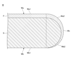
- FIG. 3 is a cross-sectional view showing an example of the substrate after processing.
- FIG. 4 is a cross-sectional view showing an example of a main part of the substrate processing apparatus.
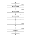
- FIG. 5 is a flowchart illustrating a substrate processing method according to one embodiment.
- FIG. 6 is a diagram showing an example of a recipe in steps S101 to S104 in FIG.
- FIG. 7 is a cross-sectional view showing an example of step S101 in FIG.
- FIG. 8 is a cross-sectional view showing an example of step S102 in FIG.
- FIG. 6 is a diagram showing an example of a recipe in steps S101 to S104 in FIG.
- FIG. 7 is a cross-sectional view showing an example of step S101 in FIG.
- FIG. 8 is a cross-sectional view showing an example of step
- FIG. 9 is a cross-sectional view showing an example of step S103 in FIG.
- FIG. 10 is a diagram showing an example of the relationship between whether or not the first processing liquid is supplied, the first rotation speed, and the cut width.
- FIG. 11 is a diagram showing an example of an imaging section.
- FIG. 12 is a diagram illustrating an example of an image captured by the imaging unit.
- the same or corresponding configurations are denoted by the same reference numerals, and the description thereof may be omitted.
- the X-axis direction, Y-axis direction, and Z-axis direction are directions perpendicular to each other.
- the X-axis direction and the Y-axis direction are horizontal, and the Z-axis direction is vertical.
- the substrate processing apparatus 1 processes the substrate W by supplying a processing liquid to the substrate W while rotating the substrate W.
- the substrate processing apparatus 1 includes, for example, a processing container 10, a substrate rotation section 20, a processing liquid supply section 30, a cup 40, and a control section 90.
- a FFU (Fan Filter Unit) 11 is provided on the ceiling of the processing container 10 .
- the FFU 11 forms a downflow inside the processing container 10 .
- a gate 12 and a gate valve 13 for opening and closing the gate 12 are provided on the side wall of the processing container 10 .
- the substrate W is transported into the processing container 10 via the gate 12 by a transport device (not shown), is treated with a processing liquid inside the processing container 10, and then transported to the outside of the processing container 10 via the gate 12 by the transport device. will be carried out.
- the substrate rotation unit 20 holds the substrate W horizontally and rotates it.
- the substrate rotation section 20 includes, for example, a holding section 21, a rotation shaft 22, and a rotation drive section 23.
- the holding unit 21 is provided inside the processing container 10 and holds the substrate W horizontally so that the center of the substrate W coincides with the rotation center line of the rotation shaft 22.
- the holding part 21 attracts, for example, the center of the lower surface of the substrate W.
- the rotation drive section 23 rotates the holding section 21 around the vertical rotation shaft 22.
- the processing liquid supply unit 30 supplies a processing liquid to the substrate W.
- the processing liquid supply section 30 includes, for example, a nozzle 31.
- the nozzle 31 is connected to a supply source of processing liquid.
- the nozzle 31 is provided inside the processing container 10 and discharges a processing liquid onto the substrate W held by the holding section 21 .
- the nozzle 31 may be a two-fluid nozzle that mixes liquid and gas and discharges the mixture.
- the nozzle 31 is movable horizontally and vertically.
- the cup 40 surrounds the peripheral edge of the substrate W held by the holding part 21 and receives the processing liquid scattered from the peripheral edge of the substrate W. Although the cup 40 does not rotate together with the rotating shaft 22 in this embodiment, it may rotate together with the rotating shaft 22.
- a drain pipe 41 and an exhaust pipe 42 are provided at the bottom of the cup 40.
- the drain pipe 41 drains the liquid accumulated inside the cup 40.
- the exhaust pipe 42 exhausts gas accumulated inside the cup 40.
- the control unit 90 is, for example, a computer, and includes a CPU (Central Processing Unit) 91 and a storage medium 92 such as a memory.
- the storage medium 92 stores programs that control various processes executed in the substrate processing apparatus 1 .
- the control unit 90 controls the operation of the substrate processing apparatus 1 by causing the CPU 91 to execute a program stored in the storage medium 92 .
- the substrate processing apparatus 1 removes the peripheral portion of the film F formed on the upper surface Wa of the substrate W (see FIGS. 2 and 3). Note that in FIGS. 2 and 3, the ratio of the thickness of the film F to the thickness of the base substrate S is displayed larger than it actually is. The thickness of the film F is actually thin, and the shape of the underlying substrate S determines the shape of the substrate W.
- the substrate W has a substrate upper surface Wa, a substrate lower surface Wb, and a substrate peripheral edge Wc.
- the upper surface Wa of the substrate is an upwardly facing surface and has a horizontal surface Wa1 and a beveled surface Wa2 provided outside the horizontal surface Wa1.
- the lower surface Wb of the substrate is a downward facing surface, and has a horizontal surface Wb1 and a beveled surface Wb2 provided outside the horizontal surface Wb1.
- the bevel surfaces Wa2 and Wb2 are so-called R surfaces, but may also be so-called C surfaces.
- the substrate W may have a vertical surface (not shown) on the substrate periphery Wc.
- the substrate W includes a base substrate S such as a silicon wafer, and a film F formed on the base substrate S.
- the base substrate S is not limited to a silicon wafer, but may be a compound semiconductor wafer or a glass substrate.
- the film F is, for example, a titanium nitride film, an aluminum film, a tungsten film, a silicon nitride film, a silicon oxide film, a polysilicon film, or a thermal oxide film.
- the film F may be formed on both the upper and lower surfaces of the base substrate S.
- a plurality of films may be stacked on the base substrate S.
- a silicon oxide film and a titanium nitride film may be formed in this order.
- a silicon oxide film, a polysilicon film, and a tungsten film may be formed in this order.
- the film F to be removed only needs to include the upper layer film and does not need to include the lower layer film.
- the film F to be removed only needs to include the upper titanium nitride film and does not need to include the lower silicon oxide film.
- the film F to be removed only needs to include the upper tungsten film and not the lower polysilicon film and silicon oxide film. It's okay.
- the film F to be removed may be a resist film and is not particularly limited.
- the cup 40 includes a horizontal bottom wall 43, an outer wall 44 extending upward from the periphery of the bottom wall 43, a separation wall 45 arranged inside the outer wall 44, and an inner wall 46 arranged inside the separation wall 45. has.
- the outer wall 44, the separation wall 45, and the inner wall 46 are arranged concentrically.
- a recess 47 for collecting liquid is formed between the outer wall 44 and the separation wall 45.
- the liquid collected in the recess 47 passes through the drain pipe 41 (see FIG. 1) and is discharged to the outside of the substrate processing apparatus 1.
- a recess 48 for collecting gas is formed between the separation wall 45 and the inner wall 46.
- the gas collected in the recess 48 passes through the exhaust pipe 42 (see FIG. 1) and is exhausted to the outside of the substrate processing apparatus 1.
- the separation wall 45 separates the outer recess 47 and the inner recess 48, and separates liquid and gas.
- the outer wall 44 of the cup 40 has an inclined surface 44a that receives liquid scattered from the periphery of the substrate W.
- the inclined surface 44a slopes downward toward the radially outer side of the substrate W.
- a passage A1 for both liquid and gas is formed between the inclined surface 44a of the outer wall 44 and the upper surface of the guide wall 49.
- a gas passage A2 is formed between the lower surface of the guide wall 49 and the upper surface of the separation wall 45.
- the guide wall 49 slopes downward from the upper end of the inner wall 46 toward the outside in the radial direction.
- the liquid passes through the passage A1 and is collected in the outer recess 47.
- the gas passes through the passages A1 and A2 and is collected into the inner recess 48.
- the substrate processing apparatus 1 includes a cover 50.
- the cover 50 is disposed above the substrate W held by the substrate rotating section 20 so as to be movable up and down.
- the cover 50 is a ring-shaped member that forms an annular gap between the cover 50 and the substrate W, and forms a strong airflow in the gap.
- the airflow flows above the substrate W and radially outward of the substrate W. By forming the airflow, it is possible to suppress mist from adhering to the upper surface Wa of the substrate.
- the cover 50 seals between an inner cylinder part 51 facing the peripheral edge of the upper surface Wa of the substrate, an outer cylinder part 52 arranged outside the inner cylinder part 51, and between the outer cylinder part 52 and the outer wall 44 of the cup 40.
- a seal portion 53 is included.
- the inner cylinder portion 51 has a circular opening when viewed from above. The diameter of the opening is smaller than the diameter of the substrate W.
- the inner cylindrical portion 51 forms a gap with the peripheral edge of the upper surface Wa of the substrate.
- the inner cylindrical portion 51 protrudes further downward than the outer cylindrical portion 52 so that the gap becomes smaller and, in turn, a strong airflow is formed in the gap.
- a notch 54 is formed in the inner edge of the cover 50, and a first nozzle 31A, which will be described later, is arranged in the notch 54.
- the first nozzle 31A is arranged so as to be movable in the radial direction of the substrate W.
- the substrate processing apparatus 1 includes a first nozzle 31A.
- the first nozzle 31A is connected to a first processing liquid supply mechanism 32A.
- the first processing liquid supply mechanism 32A includes an on-off valve, a flow meter, and a flow controller.
- the first processing liquid supply mechanism 32A supplies the first processing liquid to the first nozzle 31A.
- the first nozzle 31A supplies the first processing liquid toward the substrate W from above the substrate W held by the substrate rotation unit 20.
- the first treatment liquid inhibits the removal of the film F by the second treatment liquid described later.
- the first treatment liquid is, for example, DIW (deionized water).
- the first processing liquid After the first processing liquid is supplied to the substrate upper surface Wa (specifically, the horizontal surface Wa1 of the substrate upper surface Wa), it flows radially outward of the substrate W by centrifugal force.
- the first processing liquid suppresses the second processing liquid from flowing around from the substrate lower surface Wb to the substrate upper surface Wa via the substrate peripheral edge Wc. Further, the first treatment liquid dilutes the second treatment liquid.
- the first treatment liquid is not limited to DIW as long as it can inhibit the removal of the membrane F by the second treatment liquid.
- the first nozzle 31A may discharge the first processing liquid diagonally downward toward the outside of the substrate W in the radial direction. Thereby, the first processing liquid can be supplied to the substrate upper surface Wa without going against the centrifugal force, and it is possible to suppress the first processing liquid from scattering due to the impact when the first processing liquid collides with the substrate upper surface Wa. Although not shown, the first nozzle 31A may discharge the first processing liquid diagonally downward toward the radially outer side of the substrate W and toward the rotational direction of the substrate W.
- the substrate processing apparatus 1 includes a second nozzle 31B.
- the second nozzle 31B is connected to a second processing liquid supply mechanism 32B.
- the second processing liquid supply mechanism 32B includes an on-off valve, a flow meter, and a flow controller.
- the second processing liquid supply mechanism 32B supplies the second processing liquid to the second nozzle 31B.
- the second nozzle 31B supplies the second processing liquid toward the substrate W from below the substrate W held by the substrate rotation unit 20.
- the second treatment liquid removes the membrane F.
- the second treatment liquid is selected depending on the type of membrane F to be removed. For example, when the film F is a tungsten film or a titanium nitride film, the second treatment liquid may be a hydrogen peroxide solution.
- the second processing liquid After the second processing liquid is supplied to the substrate lower surface Wb (specifically, the horizontal surface Wb1 of the substrate lower surface Wb), it flows radially outward of the substrate W due to centrifugal force.
- the second processing liquid flows from the lower surface Wb of the substrate to the upper surface Wa of the substrate via the peripheral edge Wc of the substrate, and removes the peripheral edge of the film F.
- the second processing liquid is an etching liquid, a developing liquid, or the like, and is not particularly limited.
- the second nozzle 31B may discharge the second processing liquid diagonally upward toward the radially outer side of the substrate W. Thereby, the second processing liquid can be supplied to the substrate lower surface Wb without going against the centrifugal force, and it is possible to suppress the second processing liquid from scattering due to the impact when the second processing liquid collides with the substrate lower surface Wb. Although not shown, the second nozzle 31B may discharge the second processing liquid obliquely upward toward the radially outer side of the substrate W and toward the rotational direction of the substrate W.
- the substrate processing apparatus 1 may include a third nozzle 31C.
- the third nozzle 31C is connected to a third processing liquid supply mechanism 32C.
- the third processing liquid supply mechanism 32C includes an on-off valve, a flow meter, and a flow controller.
- the third processing liquid supply mechanism 32C supplies the third processing liquid to the third nozzle 31C.
- the third nozzle 31C supplies the third processing liquid toward the substrate W from below the substrate W held by the substrate rotation unit 20.
- the third processing liquid is supplied to the substrate W after the second processing liquid, and washes away the second processing liquid remaining on the substrate W.
- the third treatment liquid is, for example, DIW, although it is not particularly limited.
- the third processing liquid is supplied to the substrate lower surface Wb (specifically, the horizontal surface Wb1 of the substrate lower surface Wb), and then flows radially outward of the substrate W by centrifugal force.
- the third processing liquid flows from the lower surface Wb of the substrate to the upper surface Wa of the substrate via the peripheral edge Wc of the substrate, and mixes with the first processing liquid. It is preferable that the third treatment liquid is of the same type as the first treatment liquid.
- the third nozzle 31C may discharge the third processing liquid obliquely upward toward the outside of the substrate W in the radial direction. Thereby, the third processing liquid can be supplied to the substrate lower surface Wb without going against the centrifugal force, and it is possible to suppress the third processing liquid from scattering due to the impact when the third processing liquid collides with the substrate lower surface Wb. Although not shown, the third nozzle 31C may discharge the third processing liquid obliquely upward toward the radially outer side of the substrate W and toward the rotational direction of the substrate W.
- the third nozzle 31C may be arranged radially inward of the substrate W than the second nozzle 31B.
- the third processing liquid can be supplied to the entire region to which the second processing liquid is supplied, and the residue of the second processing liquid can be reduced.
- the substrate processing method includes steps S101 to S106, for example. Steps S101 to S106 are performed under the control of the control section 90. The processing from step S101 onwards is started when a transport device (not shown) carries the substrate W into the processing container 10 and the substrate rotation section 20 holds the substrate W horizontally.
- step S101 includes supplying the first processing liquid L1 through the first nozzle 31A while the substrate W is rotated at a first rotation speed n1 by the substrate rotation unit 20. .
- the first processing liquid L1 flows radially outward of the substrate W after being supplied to the substrate upper surface Wa (specifically, the horizontal surface Wa1 of the substrate upper surface Wa).
- the first processing liquid L1 may go around the substrate periphery Wc and reach the substrate lower surface Wb.
- the second processing liquid L2 and the third processing liquid L3 are not supplied to the substrate W.
- step S102 the second processing liquid L2 is supplied by the second nozzle 31B while the substrate W is rotated at the first rotation speed n1 by the substrate rotation unit 20. After being supplied to the lower surface Wb of the substrate, the second processing liquid L2 flows from the lower surface Wb of the substrate to the upper surface Wa of the substrate via the peripheral edge Wc of the substrate, and removes the peripheral edge of the film F.
- step S102 not only the second processing liquid L2 but also the first processing liquid L1 is supplied to the substrate W.
- the first treatment liquid L1 suppresses the circulation of the second treatment liquid L2, dilutes the second treatment liquid L2, and inhibits removal of the film F by the second treatment liquid L2.
- a boundary B between the covered portion and the exposed portion is formed on the upper surface Wa of the substrate.
- the covered portion is the portion where the film F remains, and the exposed portion is the portion where the film F is removed.
- the exposed portion is formed on the radially outer side of the covering portion.
- the width CW of the exposed portion when viewed from above is also referred to as the cut width CW.
- the first treatment liquid L1 suppresses the second treatment liquid L2 from going around and dilutes the second treatment liquid L2, thereby inhibiting the removal of the film F by the second treatment liquid L2.
- the cut width CW can be made smaller than when the first treatment liquid L1 is not supplied (see FIG. 10).
- the cut width CW By reducing the cut width CW, it is possible to enlarge the effective area (for example, the area where a chip is formed) in the horizontal surface Wa1 of the upper surface Wa of the substrate. Further, by reducing the cut width CW, a wide range of the horizontal surface Wa1 of the substrate upper surface Wa can be protected by the covering portion in the subsequent etching process, and the occurrence of defects such as voids can be suppressed.
- the second processing liquid L2 is supplied to the substrate lower surface Wb, and then flows from the substrate lower surface Wb to the substrate upper surface Wa via the substrate periphery Wc.
- the cut width CW can be controlled by the first rotation speed n1. The larger the first rotation speed n1 is, the larger the centrifugal force is, the more the second processing liquid L2 is suppressed from going around, and the cut width CW becomes smaller (see FIG. 10).
- the cut width CW is determined by the supply position. If an attempt is made to control the cut width CW by the supply position of the second processing liquid L2, the shape of the boundary B when viewed from above tends to be a jagged circle instead of a neat circle. When the cut width CW is small, fluctuations in the cut width CW are easily noticeable. Furthermore, if you try to directly supply the second processing liquid L2 to the beveled surface Wa2 of the upper surface Wa of the substrate, the supply position will change no matter what, and the shape of the boundary B when viewed from above will become a jagged circle. Prone.
- the second processing liquid L2 is supplied to the substrate lower surface Wb, and then flows from the substrate lower surface Wb to the substrate upper surface Wa via the substrate periphery Wc.
- the cut width CW can be controlled by the first rotation speed n1.
- the first processing liquid L1 can stabilize the circulation of the second processing liquid L2. Therefore, the shape of the boundary B when viewed from above can be approximated to a clean circle. In other words, the cut width CW can be stably reduced.
- the cut width CW can be stably reduced, it is also possible to remove the peripheral edge of the film F so that the boundary B remains on the beveled surface Wa2.
- the control unit 90 removes the peripheral edge of the film F so that the boundary B remains on the beveled surface Wa2, or removes the peripheral edge of the film F so that the boundary B exceeds the beveled surface Wa2 and reaches the horizontal surface Wa1.
- the first rotation speed n1 may be set larger. It is preferable to set the first rotation speed n1 to 800 rpm to 2400 rpm.
- the control unit 90 controls the first nozzle 31A to start supplying the first processing liquid L1, and then the second nozzle 31B to start supplying the second processing liquid L2. .
- the control unit 90 starts supplying the second processing liquid L2 after the first processing liquid L1 reaches the substrate peripheral edge Wc.
- step S103 as shown in FIGS. 6 and 9, the substrate W is rotated by the substrate rotation unit 20 at a second rotation speed n2 smaller than the first rotation speed n1, and the third nozzle 31C performs a third process.
- Step S103 is performed after the control for stopping the supply of the second treatment liquid L2 and removing the peripheral portion of the film F is completed.
- the second processing liquid L2 remaining on the substrate W can be washed away with the third processing liquid L3.
- the second rotation speed n2 is, for example, 400 rpm to 800 rpm.
- the position of the first nozzle 31A is preferably fixed in order to suppress the generation of mist.
- step S104 includes drying the substrate W by rotating the substrate W at a third rotation speed n3 that is larger than the first rotation speed n1 by the substrate rotation unit 20.
- Step S104 is performed after the supply of the first processing liquid L1 and the third processing liquid L3 is stopped.
- the third rotation speed n3 is, for example, 2200 rpm to 3000 rpm.
- step S105 includes capturing an image of the peripheral edge of the substrate W viewed from the side using the imaging unit 60.
- the processes after step S105 may be performed before the substrate W is carried out of the processing container 10, or may be carried out after the substrate W is carried out. That is, the imaging unit 60 may be provided inside the processing container 10 or may be provided outside the processing container 10.
- the imaging unit 60 is a camera.
- the camera may be either a color camera or a monochrome camera.
- the imaging unit 60 captures an image P (see FIG. 12) of the peripheral edge of the substrate W viewed from the side, for example, via a curved mirror 61 and a flat mirror 62.
- the curved mirror 61 is arranged on the side of the peripheral edge of the substrate W, and the plane mirror 62 is arranged above the curved mirror 61. Note that the curved mirror 61 and the flat mirror 62 may be omitted, and the imaging section 60 may be arranged on the side of the peripheral edge of the substrate W.
- the imaging unit 60 may capture an image of the peripheral edge of the substrate W viewed from above, but preferably captures an image P of the peripheral edge of the substrate W viewed from the side as shown in FIG.
- the imaging unit 60 may capture an image of the peripheral edge of the substrate W viewed from above, but preferably captures an image P of the peripheral edge of the substrate W viewed from the side as shown in FIG.
- step S106 the image P is processed to detect the boundary B and estimate the cut width CW.
- the relationship between the coordinates of the boundary B in the image P and the cut width CW is stored in advance for each shape of the bevel surface Wa2.
- the control unit 90 estimates the cut width CW by referring to information stored in advance.
- the relationship between the coordinates of the boundary B in the image P, the angle ⁇ shown in FIG. 3, and the cut width CW may be stored in advance.
- the angle ⁇ is the angle formed by the horizontal line and a straight line connecting the boundary B and the intersection O of the vertical line passing through the upper end of the beveled surface Wa2 and the horizontal line passing through the lower end of the beveled surface Wa2.
- the control unit 90 may estimate the angle ⁇ and the cut width CW by referring to information stored in advance.
- the control unit 90 may perform control to display the image P on an image display device.
- the image P to be displayed may include a scale indicating the size of at least one of the cut width CW and the angle ⁇ , as shown in FIG.
- the vertical coordinate of the image P may be proportional to the angle ⁇ , for example.
- a substrate processing apparatus for removing a peripheral portion of a film formed on an upper surface of a substrate comprising: a substrate rotation unit that holds and rotates the substrate horizontally; a first nozzle that supplies a first treatment liquid that inhibits removal of the film from above the substrate held in the substrate rotation unit; a second nozzle that supplies a second processing liquid for removing the film from below the substrate held in the substrate rotation unit; a control unit that controls rotation of the substrate, supply of the first treatment liquid, and supply of the second treatment liquid; Equipped with The control unit is configured to supply the first treatment liquid through the first nozzle and supply the second treatment liquid through the second nozzle while the substrate rotation unit rotates the substrate at a first rotation speed.
- a substrate processing apparatus that performs control to remove a peripheral portion of the film by supplying the film.
- the upper surface of the substrate held by the substrate rotation unit has a horizontal surface and a beveled surface provided outside the horizontal surface, The substrate according to supplementary note 1, wherein the control unit performs control to remove a peripheral portion of the film so that a boundary between a covered portion where the film remains and an exposed portion from which the film is removed remains on the beveled surface.
- Processing equipment may remove the peripheral edge of the membrane such that the boundary remains on the beveled surface, or remove the peripheral edge of the membrane such that the boundary exceeds the beveled surface and reaches the horizontal surface.
- the substrate processing apparatus which performs control to set the first rotation speed to be larger than that of the substrate processing apparatus.
- an imaging unit that captures an image of the peripheral edge of the substrate viewed from the side;
- the substrate processing apparatus according to appendix 2 or 3, wherein the control unit processes the image to detect the boundary and estimate the width of the exposed portion when viewed from above.
- the first nozzle discharges the first processing liquid diagonally downward toward the outside in the radial direction of the substrate; the second nozzle discharges the second processing liquid diagonally upward toward the outside in the radial direction of the substrate; Any one of Supplementary Notes 1 to 4, wherein the control unit performs control such that the second nozzle starts supplying the second processing liquid after the first nozzle starts supplying the first processing liquid.
- the substrate processing apparatus described in . comprising a third nozzle that supplies a third processing liquid from below the substrate held in the substrate rotation unit, The control unit causes the substrate rotation unit to rotate the substrate at a rotation speed higher than the first rotation speed after the second nozzle stops supplying the second processing liquid and removes the peripheral edge of the film.
- a substrate processing method comprising removing a peripheral portion of a film formed on an upper surface of a substrate, the method comprising: While the substrate is being rotated at a first rotation speed, a first treatment liquid that inhibits the removal of the film is supplied from a first nozzle above the substrate toward the substrate, and a first treatment liquid that inhibits the removal of the film is supplied from a first nozzle above the substrate.
- a substrate processing method comprising removing a peripheral portion of the film by supplying a second processing liquid for removing the film from a second nozzle toward the substrate.
- the upper surface of the substrate rotated at the first rotation speed has a horizontal surface and a beveled surface provided outside the horizontal surface
- the substrate processing method includes removing a peripheral portion of the film such that a boundary between a covered portion where the film remains and an exposed portion from which the film is removed remains on the beveled surface.
- Substrate processing method When the periphery of the membrane is removed so that the boundary remains on the beveled surface, the periphery of the membrane is removed such that the boundary extends beyond the beveled surface to the horizontal surface.
- the substrate processing method according to supplementary note 8 comprising setting the first rotation speed to a large value.
- the method includes capturing an image of the peripheral edge of the substrate viewed from the side, and processing the image to detect the boundary and estimate the width of the exposed portion when viewed from above. , the substrate processing method according to appendix 8 or 9.
- the first nozzle discharges the first processing liquid diagonally downward toward the outside in the radial direction of the substrate; the second nozzle discharges the second processing liquid diagonally upward toward the outside in the radial direction of the substrate;
- the substrate processing method may include starting the supply of the second processing liquid through the second nozzle after the first nozzle starts supplying the first processing liquid. Substrate processing method described in section.
- the substrate is rotated at a second rotation speed smaller than the first rotation speed, and the lower part of the substrate is rotated.
- the substrate processing method according to any one of appendices 7 to 11, comprising supplying a third processing liquid toward the substrate from a third nozzle.
- Substrate processing apparatus 20 Substrate rotating section 31A First nozzle 31B Second nozzle 90 Control section W Substrate F Film
Landscapes
- Cleaning Or Drying Semiconductors (AREA)
- Chemical & Material Sciences (AREA)
- Chemical Kinetics & Catalysis (AREA)
- General Chemical & Material Sciences (AREA)
Priority Applications (4)
| Application Number | Priority Date | Filing Date | Title |
|---|---|---|---|
| KR1020247037056A KR20250006088A (ko) | 2022-04-18 | 2023-04-04 | 기판 처리 장치 및 기판 처리 방법 |
| US18/855,160 US20250253166A1 (en) | 2022-04-18 | 2023-04-04 | Substrate processing apparatus and substrate processing method |
| CN202380032753.8A CN118985039A (zh) | 2022-04-18 | 2023-04-04 | 基片处理装置和基片处理方法 |
| JP2024516174A JP7749815B2 (ja) | 2022-04-18 | 2023-04-04 | 基板処理装置、および基板処理方法 |
Applications Claiming Priority (2)
| Application Number | Priority Date | Filing Date | Title |
|---|---|---|---|
| JP2022068333 | 2022-04-18 | ||
| JP2022-068333 | 2022-04-18 |
Publications (1)
| Publication Number | Publication Date |
|---|---|
| WO2023204017A1 true WO2023204017A1 (ja) | 2023-10-26 |
Family
ID=88419829
Family Applications (1)
| Application Number | Title | Priority Date | Filing Date |
|---|---|---|---|
| PCT/JP2023/013963 Ceased WO2023204017A1 (ja) | 2022-04-18 | 2023-04-04 | 基板処理装置、および基板処理方法 |
Country Status (6)
| Country | Link |
|---|---|
| US (1) | US20250253166A1 (https=) |
| JP (1) | JP7749815B2 (https=) |
| KR (1) | KR20250006088A (https=) |
| CN (1) | CN118985039A (https=) |
| TW (1) | TW202422734A (https=) |
| WO (1) | WO2023204017A1 (https=) |
Citations (7)
| Publication number | Priority date | Publication date | Assignee | Title |
|---|---|---|---|---|
| JPH0878378A (ja) * | 1994-09-08 | 1996-03-22 | Toshiba Corp | 半導体基板の表面処理方法 |
| JP2000269178A (ja) * | 1999-03-15 | 2000-09-29 | Nec Corp | エッチング除去方法および装置と洗浄方法および装置 |
| JP2001319910A (ja) * | 2000-05-08 | 2001-11-16 | Tokyo Electron Ltd | 液処理装置 |
| JP2014063910A (ja) * | 2012-09-21 | 2014-04-10 | Tokyo Electron Ltd | 液処理方法、液処理装置及び液処理用記録媒体 |
| JP2016139743A (ja) * | 2015-01-28 | 2016-08-04 | 東京エレクトロン株式会社 | ウエットエッチング方法、基板液処理装置および記憶媒体 |
| JP2019212804A (ja) * | 2018-06-06 | 2019-12-12 | 東京エレクトロン株式会社 | 塗布膜形成装置及び塗布膜形成装置の調整方法 |
| JP2021141087A (ja) * | 2020-02-28 | 2021-09-16 | 株式会社Screenホールディングス | 基板処理方法および基板処理装置 |
Family Cites Families (1)
| Publication number | Priority date | Publication date | Assignee | Title |
|---|---|---|---|---|
| JP6541605B2 (ja) | 2016-03-30 | 2019-07-10 | 東京エレクトロン株式会社 | 基板処理装置、及び基板処理装置の撮像方法 |
-
2023
- 2023-04-04 CN CN202380032753.8A patent/CN118985039A/zh active Pending
- 2023-04-04 KR KR1020247037056A patent/KR20250006088A/ko active Pending
- 2023-04-04 JP JP2024516174A patent/JP7749815B2/ja active Active
- 2023-04-04 US US18/855,160 patent/US20250253166A1/en active Pending
- 2023-04-04 WO PCT/JP2023/013963 patent/WO2023204017A1/ja not_active Ceased
- 2023-04-10 TW TW112113192A patent/TW202422734A/zh unknown
Patent Citations (7)
| Publication number | Priority date | Publication date | Assignee | Title |
|---|---|---|---|---|
| JPH0878378A (ja) * | 1994-09-08 | 1996-03-22 | Toshiba Corp | 半導体基板の表面処理方法 |
| JP2000269178A (ja) * | 1999-03-15 | 2000-09-29 | Nec Corp | エッチング除去方法および装置と洗浄方法および装置 |
| JP2001319910A (ja) * | 2000-05-08 | 2001-11-16 | Tokyo Electron Ltd | 液処理装置 |
| JP2014063910A (ja) * | 2012-09-21 | 2014-04-10 | Tokyo Electron Ltd | 液処理方法、液処理装置及び液処理用記録媒体 |
| JP2016139743A (ja) * | 2015-01-28 | 2016-08-04 | 東京エレクトロン株式会社 | ウエットエッチング方法、基板液処理装置および記憶媒体 |
| JP2019212804A (ja) * | 2018-06-06 | 2019-12-12 | 東京エレクトロン株式会社 | 塗布膜形成装置及び塗布膜形成装置の調整方法 |
| JP2021141087A (ja) * | 2020-02-28 | 2021-09-16 | 株式会社Screenホールディングス | 基板処理方法および基板処理装置 |
Also Published As
| Publication number | Publication date |
|---|---|
| JP7749815B2 (ja) | 2025-10-06 |
| TW202422734A (zh) | 2024-06-01 |
| KR20250006088A (ko) | 2025-01-10 |
| JPWO2023204017A1 (https=) | 2023-10-26 |
| CN118985039A (zh) | 2024-11-19 |
| US20250253166A1 (en) | 2025-08-07 |
Similar Documents
| Publication | Publication Date | Title |
|---|---|---|
| TWI757316B (zh) | 液體處理裝置及液體處理方法 | |
| TWI514450B (zh) | Surface treatment device and method for semiconductor substrate | |
| US7964042B2 (en) | Substrate processing apparatus and substrate processing method | |
| JP2008034779A (ja) | 基板処理方法および基板処理装置 | |
| TW202046836A (zh) | 基板處理方法及基板處理裝置 | |
| US12368041B2 (en) | Cleaning method of cup of substrate processing apparatus and substrate processing apparatus | |
| CN108028195B (zh) | 基板处理方法、基板处理装置以及存储介质 | |
| JP2009110985A (ja) | 基板処理方法および基板処理装置 | |
| JP5184476B2 (ja) | 基板液処理方法、基板液処理装置および記憶媒体 | |
| KR101950047B1 (ko) | 기판 세정 건조 방법 및 기판 현상 방법 | |
| JP2022190113A (ja) | 基板処理方法、及び基板処理装置 | |
| JP4236109B2 (ja) | 基板処理方法及び基板処理装置 | |
| JP2008021983A (ja) | 液処理装置および液処理方法 | |
| WO2023204017A1 (ja) | 基板処理装置、および基板処理方法 | |
| US6916126B2 (en) | Developing method for semiconductor substrate | |
| JP5020915B2 (ja) | ポリシリコン膜の除去方法、処理装置および記憶媒体 | |
| JP4940119B2 (ja) | 基板処理装置、基板処理方法及び記憶媒体 | |
| JP2003197600A (ja) | 基板周縁処理装置および基板周縁処理方法 | |
| JP5667592B2 (ja) | 基板処理装置 | |
| JP2002305173A (ja) | 基板処理装置 | |
| JP2006108349A (ja) | 基板処理方法および基板処理装置 | |
| WO2024171846A1 (ja) | 基板処理装置及び基板処理方法 | |
| CN116210074B (zh) | 基片处理装置和基片处理方法 | |
| JP2008034489A (ja) | 液処理装置 | |
| JP2006032858A (ja) | 基板処理装置 |
Legal Events
| Date | Code | Title | Description |
|---|---|---|---|
| 121 | Ep: the epo has been informed by wipo that ep was designated in this application |
Ref document number: 23791668 Country of ref document: EP Kind code of ref document: A1 |
|
| WWE | Wipo information: entry into national phase |
Ref document number: 2024516174 Country of ref document: JP |
|
| WWE | Wipo information: entry into national phase |
Ref document number: 202380032753.8 Country of ref document: CN |
|
| WWE | Wipo information: entry into national phase |
Ref document number: 1020247037056 Country of ref document: KR |
|
| NENP | Non-entry into the national phase |
Ref country code: DE |
|
| 122 | Ep: pct application non-entry in european phase |
Ref document number: 23791668 Country of ref document: EP Kind code of ref document: A1 |
|
| WWP | Wipo information: published in national office |
Ref document number: 18855160 Country of ref document: US |