WO2023200005A1 - 車両用内装材 - Google Patents
車両用内装材 Download PDFInfo
- Publication number
- WO2023200005A1 WO2023200005A1 PCT/JP2023/015182 JP2023015182W WO2023200005A1 WO 2023200005 A1 WO2023200005 A1 WO 2023200005A1 JP 2023015182 W JP2023015182 W JP 2023015182W WO 2023200005 A1 WO2023200005 A1 WO 2023200005A1
- Authority
- WO
- WIPO (PCT)
- Prior art keywords
- skin
- base material
- layer
- skin material
- vehicle
- Prior art date
- Legal status (The legal status is an assumption and is not a legal conclusion. Google has not performed a legal analysis and makes no representation as to the accuracy of the status listed.)
- Ceased
Links
Images





Classifications
-
- B—PERFORMING OPERATIONS; TRANSPORTING
- B60—VEHICLES IN GENERAL
- B60R—VEHICLES, VEHICLE FITTINGS, OR VEHICLE PARTS, NOT OTHERWISE PROVIDED FOR
- B60R13/00—Elements for body-finishing, identifying, or decorating; Arrangements or adaptations for advertising purposes
- B60R13/02—Internal Trim mouldings ; Internal Ledges; Wall liners for passenger compartments; Roof liners
- B60R13/0237—Side or rear panels
- B60R13/0243—Doors
-
- B—PERFORMING OPERATIONS; TRANSPORTING
- B29—WORKING OF PLASTICS; WORKING OF SUBSTANCES IN A PLASTIC STATE IN GENERAL
- B29C—SHAPING OR JOINING OF PLASTICS; SHAPING OF MATERIAL IN A PLASTIC STATE, NOT OTHERWISE PROVIDED FOR; AFTER-TREATMENT OF THE SHAPED PRODUCTS, e.g. REPAIRING
- B29C65/00—Joining or sealing of preformed parts, e.g. welding of plastics materials; Apparatus therefor
- B29C65/70—Joining or sealing of preformed parts, e.g. welding of plastics materials; Apparatus therefor by moulding
-
- B—PERFORMING OPERATIONS; TRANSPORTING
- B32—LAYERED PRODUCTS
- B32B—LAYERED PRODUCTS, i.e. PRODUCTS BUILT-UP OF STRATA OF FLAT OR NON-FLAT, e.g. CELLULAR OR HONEYCOMB, FORM
- B32B27/00—Layered products comprising a layer of synthetic resin
- B32B27/06—Layered products comprising a layer of synthetic resin as the main or only constituent of a layer, which is next to another layer of the same or of a different material
- B32B27/065—Layered products comprising a layer of synthetic resin as the main or only constituent of a layer, which is next to another layer of the same or of a different material of foam
-
- B—PERFORMING OPERATIONS; TRANSPORTING
- B32—LAYERED PRODUCTS
- B32B—LAYERED PRODUCTS, i.e. PRODUCTS BUILT-UP OF STRATA OF FLAT OR NON-FLAT, e.g. CELLULAR OR HONEYCOMB, FORM
- B32B27/00—Layered products comprising a layer of synthetic resin
- B32B27/32—Layered products comprising a layer of synthetic resin comprising polyolefins
-
- B—PERFORMING OPERATIONS; TRANSPORTING
- B32—LAYERED PRODUCTS
- B32B—LAYERED PRODUCTS, i.e. PRODUCTS BUILT-UP OF STRATA OF FLAT OR NON-FLAT, e.g. CELLULAR OR HONEYCOMB, FORM
- B32B3/00—Layered products comprising a layer with external or internal discontinuities or unevennesses, or a layer of non-planar shape; Layered products comprising a layer having particular features of form
- B32B3/26—Layered products comprising a layer with external or internal discontinuities or unevennesses, or a layer of non-planar shape; Layered products comprising a layer having particular features of form characterised by a particular shape of the outline of the cross-section of a continuous layer; characterised by a layer with cavities or internal voids ; characterised by an apertured layer
- B32B3/266—Layered products comprising a layer with external or internal discontinuities or unevennesses, or a layer of non-planar shape; Layered products comprising a layer having particular features of form characterised by a particular shape of the outline of the cross-section of a continuous layer; characterised by a layer with cavities or internal voids ; characterised by an apertured layer characterised by an apertured layer, the apertures going through the whole thickness of the layer, e.g. expanded metal, perforated layer, slit layer regular cells B32B3/12
-
- B—PERFORMING OPERATIONS; TRANSPORTING
- B32—LAYERED PRODUCTS
- B32B—LAYERED PRODUCTS, i.e. PRODUCTS BUILT-UP OF STRATA OF FLAT OR NON-FLAT, e.g. CELLULAR OR HONEYCOMB, FORM
- B32B3/00—Layered products comprising a layer with external or internal discontinuities or unevennesses, or a layer of non-planar shape; Layered products comprising a layer having particular features of form
- B32B3/26—Layered products comprising a layer with external or internal discontinuities or unevennesses, or a layer of non-planar shape; Layered products comprising a layer having particular features of form characterised by a particular shape of the outline of the cross-section of a continuous layer; characterised by a layer with cavities or internal voids ; characterised by an apertured layer
- B32B3/30—Layered products comprising a layer with external or internal discontinuities or unevennesses, or a layer of non-planar shape; Layered products comprising a layer having particular features of form characterised by a particular shape of the outline of the cross-section of a continuous layer; characterised by a layer with cavities or internal voids ; characterised by an apertured layer characterised by a layer formed with recesses or projections, e.g. hollows, grooves, protuberances, ribs
-
- B—PERFORMING OPERATIONS; TRANSPORTING
- B32—LAYERED PRODUCTS
- B32B—LAYERED PRODUCTS, i.e. PRODUCTS BUILT-UP OF STRATA OF FLAT OR NON-FLAT, e.g. CELLULAR OR HONEYCOMB, FORM
- B32B5/00—Layered products characterised by the non- homogeneity or physical structure, i.e. comprising a fibrous, filamentary, particulate or foam layer; Layered products characterised by having a layer differing constitutionally or physically in different parts
- B32B5/18—Layered products characterised by the non- homogeneity or physical structure, i.e. comprising a fibrous, filamentary, particulate or foam layer; Layered products characterised by having a layer differing constitutionally or physically in different parts characterised by features of a layer of foamed material
-
- B—PERFORMING OPERATIONS; TRANSPORTING
- B60—VEHICLES IN GENERAL
- B60R—VEHICLES, VEHICLE FITTINGS, OR VEHICLE PARTS, NOT OTHERWISE PROVIDED FOR
- B60R13/00—Elements for body-finishing, identifying, or decorating; Arrangements or adaptations for advertising purposes
- B60R13/02—Internal Trim mouldings ; Internal Ledges; Wall liners for passenger compartments; Roof liners
-
- F—MECHANICAL ENGINEERING; LIGHTING; HEATING; WEAPONS; BLASTING
- F16—ENGINEERING ELEMENTS AND UNITS; GENERAL MEASURES FOR PRODUCING AND MAINTAINING EFFECTIVE FUNCTIONING OF MACHINES OR INSTALLATIONS; THERMAL INSULATION IN GENERAL
- F16B—DEVICES FOR FASTENING OR SECURING CONSTRUCTIONAL ELEMENTS OR MACHINE PARTS TOGETHER, e.g. NAILS, BOLTS, CIRCLIPS, CLAMPS, CLIPS OR WEDGES; JOINTS OR JOINTING
- F16B5/00—Joining sheets or plates, e.g. panels, to one another or to strips or bars parallel to them
- F16B5/06—Joining sheets or plates, e.g. panels, to one another or to strips or bars parallel to them by means of clamps or clips
-
- F—MECHANICAL ENGINEERING; LIGHTING; HEATING; WEAPONS; BLASTING
- F16—ENGINEERING ELEMENTS AND UNITS; GENERAL MEASURES FOR PRODUCING AND MAINTAINING EFFECTIVE FUNCTIONING OF MACHINES OR INSTALLATIONS; THERMAL INSULATION IN GENERAL
- F16B—DEVICES FOR FASTENING OR SECURING CONSTRUCTIONAL ELEMENTS OR MACHINE PARTS TOGETHER, e.g. NAILS, BOLTS, CIRCLIPS, CLAMPS, CLIPS OR WEDGES; JOINTS OR JOINTING
- F16B5/00—Joining sheets or plates, e.g. panels, to one another or to strips or bars parallel to them
- F16B5/12—Fastening strips or bars to sheets or plates, e.g. rubber strips, decorative strips for motor vehicles, by means of clips
-
- B—PERFORMING OPERATIONS; TRANSPORTING
- B32—LAYERED PRODUCTS
- B32B—LAYERED PRODUCTS, i.e. PRODUCTS BUILT-UP OF STRATA OF FLAT OR NON-FLAT, e.g. CELLULAR OR HONEYCOMB, FORM
- B32B2250/00—Layers arrangement
- B32B2250/04—4 layers
-
- B—PERFORMING OPERATIONS; TRANSPORTING
- B32—LAYERED PRODUCTS
- B32B—LAYERED PRODUCTS, i.e. PRODUCTS BUILT-UP OF STRATA OF FLAT OR NON-FLAT, e.g. CELLULAR OR HONEYCOMB, FORM
- B32B2266/00—Composition of foam
- B32B2266/02—Organic
- B32B2266/0214—Materials belonging to B32B27/00
- B32B2266/025—Polyolefin
-
- B—PERFORMING OPERATIONS; TRANSPORTING
- B32—LAYERED PRODUCTS
- B32B—LAYERED PRODUCTS, i.e. PRODUCTS BUILT-UP OF STRATA OF FLAT OR NON-FLAT, e.g. CELLULAR OR HONEYCOMB, FORM
- B32B2307/00—Properties of the layers or laminate
- B32B2307/10—Properties of the layers or laminate having particular acoustical properties
- B32B2307/102—Insulating
-
- B—PERFORMING OPERATIONS; TRANSPORTING
- B32—LAYERED PRODUCTS
- B32B—LAYERED PRODUCTS, i.e. PRODUCTS BUILT-UP OF STRATA OF FLAT OR NON-FLAT, e.g. CELLULAR OR HONEYCOMB, FORM
- B32B2307/00—Properties of the layers or laminate
- B32B2307/70—Other properties
- B32B2307/72—Density
-
- B—PERFORMING OPERATIONS; TRANSPORTING
- B32—LAYERED PRODUCTS
- B32B—LAYERED PRODUCTS, i.e. PRODUCTS BUILT-UP OF STRATA OF FLAT OR NON-FLAT, e.g. CELLULAR OR HONEYCOMB, FORM
- B32B2605/00—Vehicles
- B32B2605/003—Interior finishings
-
- B—PERFORMING OPERATIONS; TRANSPORTING
- B60—VEHICLES IN GENERAL
- B60N—SEATS SPECIALLY ADAPTED FOR VEHICLES; VEHICLE PASSENGER ACCOMMODATION NOT OTHERWISE PROVIDED FOR
- B60N2/00—Seats specially adapted for vehicles; Arrangement or mounting of seats in vehicles
- B60N2/75—Arm-rests
- B60N2/78—Arm-rests post or panel mounted
Definitions
- the present invention relates to vehicle interior materials.
- Patent Document 1 and Patent Document 2 disclose a laminate (vehicle interior material) having a base material and a skin material adhered to the base material.
- the skin material is formed by joining a skin sheet forming the appearance and a foam sheet.
- a vehicle interior material is formed by joining the foam sheet side of the skin material to the base material.
- the base material and the skin material can be bonded by pressure bonding using an adhesive (Patent Document 2), or by placing a hot melt sheet between the base material and the skin material and melting the hot melt sheet (Patent Document 3). It is publicly known.
- Air pockets occur between the base material and the skin material. Air pockets may cause the foam sheet and the base material to separate or float.
- an object of the present invention is to suppress air pockets formed between a skin material and a base material in a vehicle interior material.
- an embodiment of the present invention is a vehicle interior material (1) comprising a base material (6) and a skin material (7) joined to the base material,
- the skin material includes a skin layer (8), a foam layer (9) provided on a surface of the skin layer on the base material side, and a foam material layer (9) provided on the surface of the foam material layer on the base material side.
- the air between the skin material and the base material is pushed out of the vehicle interior material along each first recess. This suppresses air pockets formed between the skin material and the base material.
- each of the bottoms of the plurality of first recesses may reach the foam material layer.
- the air between the skin material and the base material is more effectively pushed out to the outside of the vehicle interior material. Therefore, air pockets formed between the skin material and the base material are more effectively suppressed.
- the surface of the base material that is joined to the solid layer may have a plurality of second recesses (14) that are recessed toward the inside of the base material.
- a portion of the plurality of first recesses and a portion of the plurality of second recesses may be arranged to face each other.
- the second recess forms a larger air flow path toward the outside of the vehicle interior material.
- the air between the skin material and the base material is more effectively pushed out of the vehicle interior material. Therefore, air pockets formed between the skin material and the base material are more effectively suppressed.
- the foam layer has air permeability
- the skin layer may have a plurality of through holes (16) penetrating from the surface of the skin layer to the back surface of the skin layer.
- an air flow path that passes through the foam material layer and reaches the through hole is further formed.
- the air between the skin material and the base material is more effectively pushed out of the vehicle interior material. Therefore, air pockets formed between the skin material and the base material are suppressed.
- each of the plurality of through holes may be aligned with a part of the plurality of first recesses in a side view.
- the air flow path is the shortest in the matching through hole and first recess.
- each of the plurality of through holes may be aligned with a part of the plurality of second recesses in a side view.
- the air flow path is the shortest in the matching through hole and second recess. Due to these, the air between the skin material and the base material is more effectively pushed out to the outside of the vehicle interior material. Therefore, air pockets formed between the skin material and the base material are suppressed.
- the base material may have a plurality of second through holes (31) that penetrate from the front surface of the base material to the back surface of the base material.
- the air between the skin material and the base material passes through the second through hole and flows to the outside of the vehicle interior material. Therefore, air pockets formed between the skin material and the base material are more effectively suppressed.
- each of the plurality of second through holes may be aligned with a part of the plurality of first recesses in a side view.
- the first recess communicates with the outside via the second through hole. That is, the air between the skin material and the base material not only flows along the first recess, but also passes through the second through hole and flows to the outside of the vehicle interior material. Therefore, air pockets formed between the skin material and the base material are more effectively suppressed.
- the skin layer has a plurality of first through holes (16) penetrating from the surface of the skin layer to the back surface of the skin layer, and when the skin material and the base material are bonded, Each of the plurality of second through holes may be aligned with a part of the plurality of first through holes in a side view.
- the air between the skin material and the base material flows to the outside of the vehicle interior material from the base material side and the skin material side. At this time, the air flow path becomes the shortest. Therefore, air pockets formed between the skin material and the base material are more effectively suppressed.
- Patent Document 4 Japanese Unexamined Patent Publication No. 2018-69651 discloses a vehicle interior material having a base material and a skin material adhered to the base material.
- the skin material described in Patent Document 4 is provided with decorative stitches to add design.
- the decorative stitches described in Patent Document 4 are arranged on the skin material so as to protrude outward from the surface of the skin material. Therefore, there is room for improvement in design. Furthermore, there is a risk that the decorative stitches may be damaged if they get caught by a passenger or the like.
- Another aspect of the present invention is to provide a vehicle interior material with improved design and durability in an apparatus for manufacturing a vehicle interior material and a method for manufacturing a vehicle interior material.
- the present invention provides a vehicle interior material (101) that includes a base material (112) and a skin material (107) joined to the base material and including stitches (106).
- the surface of the base material to which the skin material is joined is provided with a groove (114) for receiving the portion of the skin material provided with the stitches.
- the stitches are arranged in the portion recessed into the interior of the skin material from the surface of the skin material.
- a plurality of irregularities are provided on the vehicle interior material, and a three-dimensional pattern is formed.
- the design quality is further improved. Since the stitches are arranged in the recessed portion of the skin material, the chance of the stitches being caught by passengers or the like is suppressed. Therefore, damage to the stitches is suppressed. That is, durability is further improved.
- the depth of the groove may be greater than the thickness of the stitch.
- the stitches are arranged in a recessed state from the front surface of the skin material to the back surface.
- the base material may be formed with a plurality of through holes (118) that penetrate from the front surface of the base material to the back surface of the base material.
- the through hole may be formed to penetrate from the front surface of the base material where the groove is provided to the back surface of the base material.
- the edge of the groove may be provided with a chamfer (116) that slopes from the surface of the base material toward the bottom of the groove.
- a portion of the stitch may be aligned with a component in the depth direction of the groove of the chamfer.
- the stitches are arranged in a recessed state from the front surface of the skin material to the back surface.
- a tape material (117) may be provided in the portion of the skin material where the stitches are provided.
- a skin material (107) having stitches (106) and a base material (112) having a groove portion (114) for receiving a portion of the skin material provided with the stitches are bonded to each other.
- a manufacturing method for a vehicle interior material for forming an interior material (101), the manufacturing device (120) for joining the skin material and the base material It has a first mold (121) and a second mold (122) that are movable relative to each other in the pressing direction, and one of the first mold and the second mold has a protrusion (122) that protrudes toward the other. 123) is provided, and the base material and the skin material are arranged between the first mold and the second mold so that the stitches, the grooves, and the convex parts are aligned (FIG. 13) (A)) and a pressing step (FIG. 13(B)) of moving the first mold and the second mold close to each other and pressing the skin material and the base material.
- the portion of the skin material provided with the stitches is pressed by the convex portion into the groove portion provided in the base material.
- a plurality of irregularities are provided on the vehicle interior material, and a three-dimensional pattern is formed. It is possible to provide a vehicle interior material with improved design quality.
- the convex portion is configured to be movable in the pressing direction
- the pressing step is a first pressing step of pressing a portion of the skin material other than the portion where the stitch is provided against the base material.
- FIG. 14(C) a second pressing step in which, after the first pressing step, the convex portion is moved and the portion of the skin material provided with the stitches is pressed against the groove portion (FIG. 14(B)). )).
- the pressing step of pressing the skin material and the base material is performed in stages in the first pressing step and the second pressing step, the air is formed between the skin material and the base material. Accumulation is suppressed.
- a tape material may be provided in the portion of the skin material where the stitches are provided, and in the placement step, the tape material and the groove portion may be aligned.
- Another aspect is a manufacturing apparatus (120) for a vehicle interior material (101) for joining a skin material (107) having stitches (106) and a base material (112), It has a first mold (121) and a second mold (122) that are mutually movable in the pressing direction to press the base material, and one of the first mold and the second mold has a mold that protrudes toward the other.
- a convex portion (123) is provided.
- the portion of the skin material provided with the stitches is pressed by the convex portion into the groove portion provided in the base material.
- a plurality of irregularities are provided on the vehicle interior material, and a three-dimensional pattern is formed. It is possible to provide a vehicle interior material with improved design quality.
- the convex portion may be configured to be movable in the pressing direction.
- the portion of the skin material provided with the stitches and the other portions can be pressed against the base material in stages. This suppresses air pockets formed between the skin material and the base material.
- Patent Document 5 Japanese Unexamined Patent Publication No. 2005-053435 discloses a vehicle interior material in which a decorative skin material is attached to a base material in order to decorate the interior of a vehicle interior.
- the skin material is attached to the base material by pushing the engaging member to which the skin material is bonded into a groove provided in the base material.
- Another aspect of the present invention is to facilitate attachment of a skin material to a base material in a vehicle interior material, and to enable flat attachment of an engaging member to the base material.
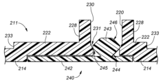
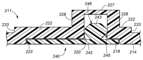
- Another aspect includes a base material (211) provided on the inside of the vehicle body panel, a skin material (212) that covers the base material from the inside of the vehicle, and an engagement member (240) for attaching the skin material to the base material.
- a first groove (220) and a second groove (218) formed around the first groove and shallower than the first groove are formed in the vehicle side part (214) of the base material
- the engagement member includes a plate portion (242) coupled to the vehicle outer side of the skin material and received in the second groove, and a locking portion (242) that protrudes from the plate portion, is inserted into the first groove, and is locked in the first groove. 243), and the interior side of the plate portion is flush with the interior side of the base material (210).
- the skin material can be attached to the base material by pushing the engagement member. Therefore, attachment of the skin material to the base material can be facilitated. Furthermore, since the interior side surface of the plate portion is flush with the interior side of the base material, the engaging member can be attached flat to the base material.
- the skin material has a first skin part (251) and a second skin part (252) that overlaps with the first skin part to form an overlapping part (253), and the first skin part and The second skin portion may be sutured to the plate portion at the overlapping portion.
- the two skin parts can be attached to the locking member by suturing.
- the second skin part is placed closer to the inside of the vehicle than the first skin part, and is folded back to the outside of the vehicle at the overlapping part.
- the end portions of the first skin part and the second skin part are not visible from inside the vehicle. Therefore, the beauty of the vehicle interior can be improved.
- the locking part is preferably arranged offset toward the first skin part with respect to the plate part.
- the skin material can be easily sutured to the plate portion. Furthermore, since the locking portion is arranged offset with respect to the plate portion, it is easy to determine the direction in which the engaging member is attached.
- the first groove preferably has a retaining portion (231) for locking the locking portion.
- the engaging member can be reliably locked to the base material. Therefore, the skin material can be reliably attached to the base material.
- the first groove has a receiving part (227, 228) that protrudes outward from the base material and covers the locking part, and the first groove has a first groove facing the locking part in the receiving part. It has an open area (226) provided with a hole (230) and a closed area (225) without the first hole, and the thickness of the receiving part in the closed area is thinner than the thickness of the locking part. good.
- the thickness of the receiving portion is formed thin. Therefore, when inserting the locking part into the first groove, the receiving part is easily bent. Therefore, the engaging member can be easily attached to the base material.
- the retaining portion is preferably provided at a position corresponding to the opening area.
- the engagement member can be attached more easily than when the retaining portion is provided over the entire base material. Therefore, work efficiency is improved.
- the base material includes a plate-shaped curved plate portion (215) having a bulged surface that bulges toward the inside of the vehicle, and the curved plate portion defines an outer edge of the bulged surface and has an arc shape in a side view.
- the skin material is arranged to cover the bulging surface from the inside of the vehicle, and the curved plate has an arcuate edge (255) on the outside surface of the curved plate at a position corresponding to the arcuate edge of the skin material.
- a resilient wire (256) is provided extending along the curved plate portion, and the resilient wire resiliently abuts against the vehicle outer side surface of the curved plate portion to hang the skin material on the arcuate edge. Good.
- the outer edge portion of the skin material can be easily attached to the base material.
- the interior material constitutes the armrest (205) of the vehicle door (201), and a plurality of engagement members are preferably arranged along the longitudinal direction of the armrest.
- an armrest equipped with an interior material that facilitates attachment of the skin material to the base material and allows the engagement member to be flatly attached to the base material. Furthermore, since a plurality of engaging members are provided, the skin material can be reliably attached even when the base material is large.
- the present invention provides a vehicle interior material (1) comprising a base material (6) and a skin material (7) joined to the base material, the skin material is a skin layer (8), a foamed material layer (9) provided on a surface of the skin layer on the side of the base material, and a foamed material layer (9) provided on the surface of the foamed material layer on the side of the base material, and
- the skin material includes a solid layer (10) having a higher density than the foam material layer, and the skin material has a plurality of first recesses (12) recessed from the solid layer toward the foam material layer.
- the air between the skin material and the base material is pushed out of the vehicle interior material along each first recess. This suppresses air pockets formed between the skin material and the base material.
- each of the bottoms of the plurality of first recesses may reach the foam material layer.
- the air between the skin material and the base material is more effectively pushed out to the outside of the vehicle interior material. Therefore, air pockets formed between the skin material and the base material are more effectively suppressed.
- the surface of the base material that is joined to the solid layer may have a plurality of second recesses (14) that are recessed toward the inside of the base material.
- a portion of the plurality of first recesses and a portion of the plurality of second recesses may be arranged to face each other.
- the second recess forms a larger air flow path toward the outside of the vehicle interior material.
- the air between the skin material and the base material is more effectively pushed out of the vehicle interior material. Therefore, air pockets formed between the skin material and the base material are more effectively suppressed.
- the foam layer has air permeability
- the skin layer may have a plurality of through holes (16) penetrating from the surface of the skin layer to the back surface of the skin layer.
- an air flow path that passes through the foam material layer and reaches the through hole is further formed.
- the air between the skin material and the base material is more effectively pushed out of the vehicle interior material. Therefore, air pockets formed between the skin material and the base material are suppressed.
- each of the plurality of through holes may be formed at a position that aligns with a part of the plurality of first recesses in a side view.
- the air flow path is the shortest in the matching through hole and first recess.
- each of the plurality of through holes may be formed at a position that aligns with a part of the plurality of second recesses in a side view.
- the air flow path is the shortest in the matching through hole and second recess. Due to these, the air between the skin material and the base material is more effectively pushed out to the outside of the vehicle interior material. Therefore, air pockets formed between the skin material and the base material are suppressed.
- the base material may have a plurality of second through holes (31) that penetrate from the front surface of the base material to the back surface of the base material.
- the air between the skin material and the base material passes through the second through hole and flows to the outside of the vehicle interior material. Therefore, air pockets formed between the skin material and the base material are more effectively suppressed.
- each of the plurality of second through holes may be aligned with a part of the plurality of first recesses in a side view.
- the first recess communicates with the outside via the second through hole. That is, the air between the skin material and the base material not only flows along the first recess, but also passes through the second through hole and flows to the outside of the vehicle interior material. Therefore, air pockets formed between the skin material and the base material are more effectively suppressed.
- the skin layer has a plurality of first through holes (16) penetrating from the surface of the skin layer to the back surface of the skin layer, and when the skin material and the base material are bonded, Each of the plurality of second through holes may be aligned with a part of the plurality of first through holes in a side view.
- the air between the skin material and the base material flows to the outside of the vehicle interior material from the base material side and the skin material side. At this time, the air flow path becomes the shortest. Therefore, air pockets formed between the skin material and the base material are more effectively suppressed.
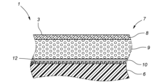
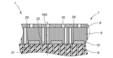
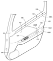
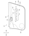
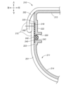
- a perspective view showing a door trim according to this embodiment A side sectional view showing the main parts of the door trim according to the first embodiment
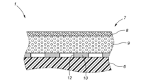
- Explanatory diagram illustrating the bonding between the base material and the skin material A side sectional view showing main parts of a door trim according to a second embodiment
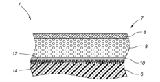
- a side sectional view showing main parts of a door trim according to a third embodiment A side sectional view showing main parts of a door trim according to a fourth embodiment
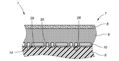
- a side sectional view showing main parts of a door trim according to a fifth embodiment A side sectional view showing main parts of a door trim according to a sixth embodiment
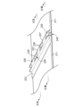
- a perspective view showing a door trim according to an eighth embodiment A diagram showing stitches provided on a door trim according to an eighth embodiment
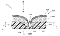
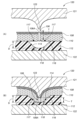
- a side sectional view showing stitches provided in a door trim according to an eighth embodiment An explanatory diagram illustrating joining of a base material and a skin material according to the eighth embodiment
- the vehicle interior material is an interior material provided in a portion of the vehicle body facing toward the passenger compartment.
- Vehicle interior materials include, for example, door trims provided on the inner surface of doors, glove boxes, instrument panels, center consoles, roof linings, and the like.
- the vehicle interior material is applied to a door trim 1 on the driver's seat side.
- the traveling direction of the vehicle in which the door trim 1 is installed is defined as the front-rear direction
- the inside in the vehicle width direction (left-right direction) is defined as the inside of the vehicle
- the outside in the vehicle width direction (left-right direction) is defined as the outside of the vehicle. do.
- the door trim 1 is provided on the inside of a metal (for example, iron) door panel P1.
- the door trim 1 has a main surface 3 facing inward in the vehicle width direction, and an edge 4 corresponding to the periphery of the main surface 3.
- the edge portion 4 extends from the end of the main surface portion 3 toward the outside of the vehicle.
- the edge portion 4 is in contact with the door panel P1, and is attached to the door panel P1 via a fastening member such as a clip (not shown), for example.
- the armrest 20 that bulges toward the inside of the vehicle is provided at the center of the door trim 1.
- the armrest 20 includes an upper wall 20A that protrudes toward the inside of the vehicle and whose main surface faces upward and downward, and a side wall that extends from the edge of the upper wall 20A on the inside of the vehicle toward the main surface 3 downward and toward the outside of the vehicle. It has 20B.
- the upper wall 20A extends horizontally toward the inside of the vehicle from the main surface portion 3. The occupant can place his or her arms on the upper surface of the upper wall 20A. This allows the armrest 20 to function as an armrest.
- a switch section 21 is provided at the front of the upper wall 20A of the armrest 20 to allow the occupant to open and close a window.
- a pull pocket body 22 defining a pull pocket space 22A recessed downward from the upper wall 20A of the armrest 20 is provided at the rear of the upper wall 20A of the armrest 20.
- the pull pocket body 22 functions as a grip portion for the occupant to grip when opening and closing the door.
- a skin material 7 is provided on the main surface portion 3.
- the skin material 7 is made of a laminate having a skin layer 8 and a foam layer 9, which will be described later, and has design properties, sound absorbing properties, and cushioning properties.
- the door trim 1 has a base material 6 joined to a skin material 7.
- the base material 6 is made of a hard resin having rigidity, and is formed to form the skeleton of the door trim 1. That is, the base material 6 forms the skeleton of the main surface portion 3, the skeleton of the armrest 20, and the skeleton of the pull pocket body 22.
- the skin material 7 is provided so as to cover the inside of the vehicle of the base material 6.
- the skin material 7 has a skin layer 8 and a foam layer 9 provided on the surface of the skin layer 8 on the base material 6 side.
- the skin layer 8 is disposed on the innermost side of the door trim 1, that is, at a position visible to the occupant.
- the skin layer 8 is formed into a sheet shape made of flexible resin, natural leather, synthetic leather, or the like in order to ensure the design of the skin material 7.
- the skin material 7 may be made of a thermoplastic elastomer (for example, a thermoplastic olefin elastomer (TPO), a thermoplastic polyvinyl chloride elastomer (TPVC), etc.) or a polyvinyl chloride resin (PVC).
- TPO thermoplastic olefin elastomer
- TPVC thermoplastic polyvinyl chloride elastomer
- PVC polyvinyl chloride resin
- Thermoplastic elastomers (TPO, TPVC, etc.) have rubber-like elasticity compared to polyvinyl chloride resin (PVC). Therefore, when the occupant touches the skin material 7, the feeling is good.
- the foam material layer 9 has a plate shape formed by foam-molding synthetic resin by a known method, and has breathability and elasticity. In other words, the foam layer 9 has a porous structure.
- the synthetic resin may be, for example, polyurethane resin (PUR), polystyrene resin (PS), polyolefin resin (polyethylene resin, polypropylene resin), or the like. Since the skin material 7 has sound absorbing properties due to the foamed material layer 9, leakage of sounds inside the vehicle interior to the outside of the vehicle is suppressed. Furthermore, since the skin material 7 has cushioning properties due to the foamed material layer 9, it also has the function of protecting the occupant (reducing the impact) in the event of a collision.
- the skin layer 8 and the foam layer 9 are joined to form the skin material 7.
- the skin layer 8 and the foamed material layer 9 may be bonded together by a known method such as a heat fusion method.
- a first molding device that is movable in the vertical direction and has a first upper mold and a first lower mold that can be opened and closed with each other to press and fuse.
- the skin layer 8 and the foamed material layer 9 are placed between the first upper mold and the first lower mold in a mutually overlapping state.
- the skin layer 8 and the foam layer 9 are pressed in the vertical direction.
- the skin layer 8 and the foam layer 9 are heated.
- the surface of the foam layer 9 that comes into contact with the skin layer 8 is melted and then hardened, so that the skin layer 8 and the foam layer 9 are fused together.
- a solid layer 10 having a higher density than the foam layer 9 is formed on the surface of the foam layer 9 on the base material 6 side. That is, the solid layer 10 has a joint surface that joins with the base material 6.
- the solid layer 10 may be formed during the process of forming the skin material 7, or may be formed as appropriate after forming the skin material 7.
- the solid layer 10 is a layer that is made denser than the foam layer 9 by applying heat to the side of the foam layer 9 that is bonded to the base material 6 and crushing the air bubbles (gaps) existing in that area. . Therefore, the solid layer 10 does not have air permeability.
- the surface of the solid layer 10 is not smooth, but has irregularities corresponding to the shape of the collapsed voids.
- the foam material layer 9 By making the solid layer 10 more dense than the foam material layer 9, the area of the solid layer 10 in contact with the base material 6 is ensured. Therefore, the bonding strength between the solid layer 10 and the base material 6 is ensured. From FIG. 2 onwards, the foam material layer 9 and the solid layer 10 are shown with different hatching to make the explanation easier to understand.
- an adhesive film may be laminated on the surface of the foam layer 9 on the base material 6 side.
- the adhesive film is a so-called hot melt adhesive that is made of a resin such as a polyolefin resin or an ethylene vinyl acetate resin, and is melted by heat.
- the thickness and basis weight of the adhesive film may be appropriately selected so as to ensure the bonding strength between the foam layer 9 and the base material 6.
- a plurality of first recesses 12 are formed in the skin material 7 and are recessed from the solid layer 10 toward the foam layer 9.
- Each of the plurality of first recesses 12 is formed by, for example, a tool such as sandpaper, and extends irregularly along the surface direction of the solid layer 10 while intersecting each other. Some ends of the plurality of first recesses 12 are formed to reach corresponding side edges of the solid layer 10.
- the plurality of first recesses 12 are formed from the inner side of the solid layer 10 in the plane direction to the outer side of the solid layer 10 in the plane direction (front-back direction in the drawing).
- the first recesses 12 are arranged at equal intervals.
- the plurality of first recesses 12 may each have a grid shape arranged in a predetermined pattern.
- the predetermined pattern may be any cross-shaped pattern such as vertical and horizontal directions, diagonal directions, or a combination thereof.
- the plurality of first recesses 12 are formed by providing a lattice-shaped convex portion on the first upper mold or first lower mold that contacts the foam material layer 9 in forming the skin material 7, so that the skin layer 8 and the foam material layer 9 may be formed when pressed.
- the plurality of first recesses 12 may be formed using a predetermined tool.
- the skin material 7 and the base material 6 are joined.
- the skin material 7 and the base material 6 may be joined by a known method such as a pressure bonding method.
- a second molding device is provided that is movable in the vertical direction in the drawing and has a second upper mold 23 and a second lower mold 24 that can be opened and closed with each other. 25 may be used.
- the second upper mold 23 has a convex portion 23A that protrudes toward the second lower mold 24 and forms the product shape of the door trim 1.
- the second lower mold 24 has a product shape of the door trim 1 and has a recess 24A for receiving the protrusion 23A of the second upper mold 23.
- the second upper mold 23 is moved in the opening/closing direction relative to the second lower mold 24 by a cylinder (not shown).
- the base material 6 is placed on the convex portion 23A of the second upper mold 23 in a state where the second upper mold 23 and the second lower mold 24 are opened to each other.
- an adhesive is applied in advance to the surface of the base material 6 to be bonded to the skin material 7, that is, the surface facing the second lower mold 24.
- the skin material 7 is placed in the recess 24A of the second lower mold 24 such that the solid layer 10 faces the second upper mold 23. At this time, it is preferable to heat the skin material 7 to soften it.
- FIG. 3(A) the base material 6 is placed on the convex portion 23A of the second upper mold 23 in a state where the second upper mold 23 and the second lower mold 24 are opened to each other.
- an adhesive is applied in advance to the surface of the base material 6 to be bonded to the skin material 7, that is, the surface facing the second lower mold 24.
- the skin material 7 is placed in the recess 24A of the second lower mold 24 such that the solid layer 10 faces the second upper mold 23.
- the second upper mold 23 is moved in a direction approaching the second lower mold 24, that is, in a downward direction in the plane of the paper. and the base material 6 are pressed in the vertical direction on the paper and bonded together. This forms the door trim 1.
- the door trim 1 according to the second embodiment differs from the door trim 1 according to the first embodiment only in the configuration of each first recess 12, and the other configurations are the same.
- the same components as those of the door trim 1 according to the first embodiment are given the same reference numerals and the description thereof will be omitted.
- each of the bottoms of the plurality of first recesses 12 is formed so as to reach the foam material layer 9. That is, a portion of the foam layer 9 is exposed to the outside.
- each of the first recesses 12 is formed by forming the solid layer 10 and then cutting out a part of the solid layer 10 using a tool or the like.
- Each of the bottoms of the plurality of first recesses 12 is formed so as to reach the foam material layer 9. Therefore, when the skin material 7 and the base material 6 are pressed in the vertical direction in the drawing, the air between the base material 6 and the skin material 7 moves toward each side edge of the solid layer 10 along the first recess 12. (in the front-rear direction in the paper) and flows toward the foam material layer 9 (in the upper direction in the paper). The air flowing toward the foam layer 9 passes through each side edge of the foam layer 9 along the voids in the foam layer 9 (in the front-rear direction and left-right direction in the page) to the outside of the foam layer 9. flows. That is, the air between the base material 6 and the skin material 7 is pushed out of the door trim 1 by utilizing the air permeability of the foam material layer 9. Therefore, air pockets formed between the skin material 7 and the base material 6 are more effectively suppressed.
- the door trim 1 according to the third embodiment differs from the door trim 1 according to the first embodiment only in the configuration of the base material 6, and the other configurations are the same.
- the same components as those of the vehicle interior material according to the first embodiment are given the same reference numerals and the description thereof will be omitted.
- a plurality of second recesses 14 are formed on the surface of the base material 6 to be joined to the foamed material layer 9, and are recessed toward the inside of the base material 6.
- the plurality of second recesses 14 may each have a grid shape arranged in a predetermined pattern.
- the predetermined pattern may be any cross-shaped pattern such as vertical and horizontal directions, diagonal directions, or a combination thereof.
- the plurality of second recesses 14 may be formed when the base material 6 is molded. Alternatively, the plurality of second recesses 14 may be formed so as to extend irregularly along the surface direction of the base material 6 while intersecting each other by using an appropriate tool. Some ends of the plurality of second recesses 14 are formed to reach corresponding side edges of the base material 6.
- the plurality of second recesses 14 are formed from the inner side of the base material 6 in the surface direction to the outer side of the base material 6 in the surface direction.
- the second recesses 14 are arranged at equal intervals.
- a portion of the plurality of second recesses 14 is arranged to face a portion of the plurality of first recesses 12.
- a plurality of second recesses 14 are formed between the base material 6 and the skin material 7.
- a portion is provided in which a portion of the first recess 12 and a portion of the plurality of first recesses 12 communicate with each other through respective openings. That is, the second recess 14 and the first recess 12 are integrated to form a larger air flow path.
- first recesses 14 there is a plurality of first recesses 14 between the base material 6 and the skin material 7 through a part of the plurality of second recesses 14 (first recesses 12). A portion with which a part of the recess 12 (second recess 14) communicates is also provided. As a result, more air flow paths are formed outside the door trim 1, that is, to each side edge of the solid layer 10 or each side edge of the base material 6, compared to the first embodiment.
- the door trim 1 according to the fourth embodiment is a combination of the door trim 1 according to the second embodiment and the door trim 1 according to the third embodiment, but compared to each embodiment, only the structure of the skin layer 8 is different. are different, and the other configurations are the same.
- the same components as the door trim 1 according to each embodiment are given the same reference numerals and the description thereof will be omitted.
- a plurality of first through holes 16 are formed in the skin layer 8, penetrating from the surface of the skin layer 8 to the back surface of the skin layer 8.
- the surface of the skin layer 8 forms a surface that is visible to the occupant.
- the back surface of the skin layer 8 forms a joint surface joined to the foam material layer 9.
- Each of the plurality of first through holes 16 may be formed using, for example, a needle or the like to be spaced apart from each other.
- a plurality of needle parts may be provided in the first upper mold or the first lower mold that contacts the skin layer 8 in forming the skin material 7, and the foam material layer 9 may be formed when the skin layer 8 and the foam material layer 9 are pressed. .
- Each of the bottoms of the plurality of first recesses 12 is formed so as to reach the foam material layer 9. That is, a portion of the foam layer 9 is exposed to the outside.
- each of the first recesses 12 is formed by forming the solid layer 10 and then cutting out a part of the solid layer 10 using a tool or the like.
- Each of the plurality of first through holes 16 is provided at a position that aligns with a portion of the plurality of first recesses 12 and a portion of the second recess 14 in a side view.
- the imaginary line 16A extending from each of the plurality of first through holes 16 in side view is A portion thereof overlaps with a portion of the plurality of first recesses 12 and a portion of the second recess 14 .
- the virtual line 16A is preferably formed so as to pass through a portion where the first recess 12 and the second recess 14 communicate with each other via their respective openings, but is not particularly limited.
- some of the plurality of virtual lines 16A may be formed so as to pass only the corresponding first recesses 12, or may be formed so as to pass only the corresponding second recesses 14.
- each portion of the plurality of virtual lines 16A that aligns with the foam material layer 9 and the solid layer 10 corresponds to the air flow (in the vertical direction of the paper) from the corresponding first recess 12 to the corresponding first through hole 16.
- the air that has flowed into the foam layer 9 is more effectively pushed out of the skin layer 8 through the first through hole 16 . Therefore, air pockets formed between the skin material 7 and the base material 6 are more effectively suppressed.
- Each of the plurality of first through holes 16 may be arranged in a predetermined direction while being spaced apart from each other, or may be arranged so as to form one unified shape or pattern as a whole. Thereby, each of the plurality of first through holes 16 can ensure the design of the door trim 1 while forming the shortest air flow path.
- a slit may be formed in the skin layer 8, penetrating from the surface of the skin layer 8 to the back surface of the skin layer 8, and extending in a predetermined direction among the surface directions of the skin layer 8.
- the air between the skin material 7 and the base material 6 is forced out of the door trim 1 through the slit and the cloth sheet.
- the slit may be covered with a breathable cloth sheet, for example. This ensures the design of the door trim 1.
- the door trim 1 according to the fifth embodiment differs from the door trim 1 according to the fourth embodiment only in the configuration of the base material 6, and the other configurations are the same.
- the same components as the door trim 1 according to the fourth embodiment are given the same reference numerals and the description thereof will be omitted.
- the base material 6 is provided with a plurality of second through holes 31 that penetrate from the front surface of the base material 6 to the back surface of the base material 6.
- the surface of the base material 6 forms a surface to be bonded to the skin material 7.
- the back surface of the base material 6 forms a surface facing the outside of the vehicle when the door trim 1 is attached to the door panel P1.
- Each second through hole 31 may be provided when the base material 6 is molded, or may be provided with a suitable tool after the base material 6 is molded.
- Each of the plurality of second through holes 31 is provided at a position that aligns with a portion of the plurality of first recesses 12 and a portion of the first through hole 16 in side view. Specifically, when the base material 6 and the skin material 7 are overlapped in order to join the base material 6 and the skin material 7, the first recesses 12 corresponding to some of the plurality of second through holes 31 are formed. They communicate with each other through their respective openings. That is, the first recess 12 communicates with the outside via the second through hole 31.
- the first recess 12 corresponding to a part of the plurality of second through holes 31 overlaps the corresponding imaginary line 16A that is an extension of the first through hole 16.
- each portion of the plurality of imaginary lines 16A that aligns from the back surface of the base material 6 to the surface of the skin layer 8 forms the shortest air flow path in the vertical direction of the paper.
- the air between the skin material 7 and the base material 6 flows along the first recess 12 to each side edge of the solid layer 10 (in the plane of the paper). flow (back and forth). Further, the air between the skin material 7 and the base material 6 passes through the foam material layer 9 and flows toward each side edge of the foam material layer 9 (in the front-rear direction and left-right direction in the paper), and It passes through the first through hole 16 and flows outward from the door trim 1 (upward in the plane of the drawing). Further, the air between the skin material 7 and the base material 6 passes through the second through hole 31 and flows to the outside of the door trim 1 (downward in the plane of the drawing). Therefore, air pockets formed between the skin material 7 and the base material 6 are more effectively suppressed.
- a slit may be formed in the base material 6, penetrating from the front surface of the base material 6 to the back surface of the base material 6, and extending in the surface direction of the base material 6. As a result, the air between the skin material 7 and the base material 6 is forced out of the door trim 1 through the slit.
- the door trim 1 according to the sixth embodiment differs from the door trim 1 according to the third embodiment only in the configurations of the foam layer 9 and the solid layer 10, and the other configurations are the same.
- the same components as the door trim 1 according to the third embodiment are given the same reference numerals and the description thereof will be omitted.
- the foam material layer 9 has a plate shape formed by foam-molding synthetic resin by a known method, and has no air permeability.
- the solid layer 10 is a layer in which the foam layer 9 is deformed by applying heat to the side of the foam layer 9 that is bonded to the base material 6 .
- the foamed material layer 9 bonded to the base material 6 has a plurality of first surfaces 28 made of the foamed material layer 9 and a plurality of second surfaces 29 made of the solid layer 10.
- the first surface 28 made of the foamed material layer 9 is provided with a plurality of third recesses 30 that are recessed toward the inside of the foamed material layer 9.
- Each of the plurality of third recesses 30 may be formed using a tool or the like, and may be formed to extend along the longitudinal direction of the corresponding first surface 28.
- a portion of the plurality of third recesses 30 and a plurality of A portion is provided in which the second recess 14 and a portion of the second recess 14 communicate with each other through respective openings. That is, the third recess 30 and the second recess 14 are integrally formed to form an air flow path.
- the air between the skin material 7 and the base material 6 flows along the third recess 30 and the second recess 14 to the solid layer 10 and the base material. It flows toward each side edge of the material 6 (in the front-rear direction on the paper).
- a larger air flow path is formed.
- the air between the skin material 7 and the base material 6 is pushed out of the door trim 1 more effectively. Therefore, even if the foam layer 9 is made of a material that does not have air permeability, when the base material 6 and the skin material 7 are bonded, air pockets formed between the skin material 7 and the base material 6 are suppressed. be done.
- the door trim 1 according to the seventh embodiment is a combination of the door trim 1 according to the fifth embodiment and the door trim 1 according to the sixth embodiment, but the structure of the foam material layer 9 is different from each embodiment. The only difference is that the other configurations are the same. In the following description, the same components as the door trim 1 according to each embodiment are given the same reference numerals and the description thereof will be omitted.
- the foam layer 9 is provided with a plurality of third through holes 32 that penetrate from the surface bonded to the base material 6 to the surface bonded to the skin layer 8.
- the third through hole 32 may be formed with a suitable tool either before or after joining with the skin layer 8, or may be formed when the foam layer 9 is molded.
- the first through hole 16 and the second through hole 31 communicate through the third through hole 32. do. That is, the door trim 1 has a portion penetrating from the inside of the vehicle to the outside of the vehicle.
- the first through hole 16 and the second through hole 31 communicate with each other via the third through hole 32, but there is no particular limitation.
- some of the plurality of third through holes 32 may communicate with only some of the corresponding first through holes 16.
- some of the plurality of third through holes 32 may communicate with only some of the corresponding second through holes 31.
- the respective axes may be offset from each other.
- the air between the skin material 7 and the base material 6 flows through the first through hole 16, the second through hole 31, and the third through hole 32 to the door trim 1. is pushed outward (up and down on the page). Therefore, even if the foam layer 9 is made of a material that does not have air permeability, air pockets formed between the skin material 7 and the base material 6 can be suppressed.
- the foam layer 9 may be provided with a slit that penetrates from the surface bonded to the base material 6 to the surface bonded to the skin layer 8 and extends in the surface direction of the first surface 28.
- the skin layer 8 does not have air permeability, but it may be a sheet made of cloth that has air permeability, such as a nonwoven fabric.
- the configurations of each embodiment may be combined as appropriate.
- vehicle interior material is an interior material provided in a portion of the vehicle body facing toward the passenger compartment.
- Vehicle interior materials include, for example, door trims provided on the inner surface of doors, glove boxes, instrument panels, center consoles, roof linings, and the like.
- the vehicle interior material is applied to a door trim 101 on the driver's seat side.
- the traveling direction of the vehicle in which the door trim 101 is installed is defined as the front-rear direction
- the inside in the vehicle width direction (left-right direction) is defined as the inside of the vehicle
- the outside in the vehicle width direction (left-right direction) is defined as the outside of the vehicle. do.
- the door trim 101 is provided on the inside of a metal (for example, iron) door panel P2.
- the door trim 101 has a main surface portion 103 facing inward in the vehicle width direction, and an edge portion 104 corresponding to the periphery of the main surface portion 103.
- the edge portion 104 extends from the end of the main surface portion 103 toward the outside of the vehicle.
- the edge portion 104 is in contact with the door panel P2, and is attached to the door panel P2 via a fastening member such as a clip (not shown), for example.
- the armrest 130 that bulges toward the inside of the vehicle is provided in the center of the door trim 101.
- the armrest 130 includes an upper wall 130A that protrudes toward the inside of the vehicle and whose main surface faces upward and downward, and a side wall that extends from the edge of the upper wall 130A on the inside of the vehicle toward the main surface portion 103 downward and toward the outside of the vehicle. It has 130B.
- the upper wall 130A extends horizontally toward the inside of the vehicle from the main surface portion 103. The occupant can place his or her arms on the upper surface of the upper wall 130A. This allows the armrest 130 to function as an armrest.
- a switch section 131 is provided at the front of the upper wall 130A of the armrest 130 to allow the occupant to open and close a window.
- a pull pocket body 132 defining a pull pocket space 132A recessed downward from the upper wall 130A of the armrest 130 is provided at the rear of the upper wall 130A of the armrest 130.
- the pull pocket body 132 functions as a grip portion for the occupant to grip when opening and closing the door.
- the skin material 107 is provided with stitches 106 as decorative members.
- the stitch 106 is formed by arranging a thread 106A in which a plurality of fibers are woven into a skin material 107 (a skin layer 108 and a foam layer 110, which will be described later).
- the stitches 106 are formed by threads 106A extending in a predetermined direction in the surface direction of the skin material 107 while being spaced apart from each other (see FIG. 12).
- the stitch 106 is arranged in a portion recessed from the surface of the skin material 107 toward the outside of the vehicle.
- the door trim 101 has a base material 112 joined to a skin material 107.
- the base material 112 is made of a hard resin having rigidity, and is formed to form the skeleton of the door trim 101. That is, the base material 112 forms the skeleton of the main surface portion 103, the skeleton of the armrest 130, and the skeleton of the pull pocket body 132.
- the skin material 107 is provided to cover the inside of the vehicle of the base material 112.
- the skin material 107 has a skin layer 108 and a foam layer 110 provided on the surface of the skin layer 108 on the base material 112 side.
- the skin layer 108 is disposed at the innermost side of the door trim 101, that is, at a position visible to the occupant.
- the skin layer 108 is formed into a sheet shape made of flexible resin, natural leather, synthetic leather, or the like in order to ensure the design of the skin material 107.
- the skin layer 108 may be composed of a thermoplastic elastomer (for example, a thermoplastic olefin elastomer (TPO), a thermoplastic polyvinyl chloride elastomer (TPVC), etc.) or a polyvinyl chloride resin (PVC).
- TPO thermoplastic olefin elastomer
- TPVC thermoplastic polyvinyl chloride elastomer
- PVC polyvinyl chloride resin
- Thermoplastic elastomers (TPO, TPVC, etc.) have rubber-like elasticity compared to polyvinyl chloride resin (PVC). Therefore, when the occupant touches the skin material 107, the feeling is good.
- the foam material layer 110 has a plate shape formed by foam-molding synthetic resin using a known method.
- the synthetic resin may be, for example, polyurethane resin (PUR), polystyrene resin (PS), polyolefin resin (polyethylene resin, polypropylene resin), or the like. Since the skin material 107 has sound absorbing properties due to the foamed material layer 110, the sound inside the vehicle cabin is suppressed from leaking to the outside of the vehicle. Further, since the skin material 107 has cushioning properties due to the foamed material layer 110, it also has the function of protecting the occupant (reducing the impact) in the event of a collision.
- the skin layer 108 and the foam layer 110 are joined to form the skin material 107.
- the skin layer 108 and the foamed material layer 110 may be joined by a known method such as a heat fusion method.
- a first molding device that is movable in the vertical direction and has a first upper mold and a first lower mold that can be opened and closed with each other to press and fuse.
- the skin layer 108 and the foamed material layer 110 are placed between the first upper mold and the first lower mold in a mutually overlapping state. Thereafter, by closing the first upper mold and the first lower mold, the skin layer 108 and the foam layer 110 are pressed in the vertical direction.
- the skin layer 108 and the foam layer 110 are heated.
- the surface of the foam layer 110 that comes into contact with the skin layer 108 is melted and then hardened, so that the skin layer 108 and the foam layer 110 are fused together.
- the stitches 106 are formed using a sewing machine or the like. Specifically, the stitches 106 are made so that the threads 106A pass through the skin material 107 alternately from the surface visible to the occupant to the back surface and from the back surface to the surface to stitch the skin layer 108 and the foam material layer 110 together. It is provided so as to extend in a predetermined direction in the plane direction of 107, that is, in the front-rear direction and the left-right direction. As a result, the stitch 106 has a thickness T from the most front side of the skin 107 to the backmost point of the skin 107 among the thread 106A, the skin layer 108, and the foam layer 110.
- the stitch 106 is a decorative member, and the thread 106A does not have to be formed to stitch the skin layer 108 and the foam material layer 110 together.
- the stitches 106 may be formed by adhering threads 106A to the surface of the skin material 107 using a suitable adhesive or the like. That is, the stitches 106 are provided so as to stand out from the surface of the skin material 107 toward the inside of the vehicle.
- a tape material 117 is provided in the portion of the skin material 107 where the stitches 106 are provided.
- the tape material 117 may be, for example, a sheet-shaped vinyl tape made of polyvinyl chloride and coated with an adhesive on one side. Tape material 117 is attached to the side edge of foam material layer 110 that aligns with the end of stitch 106 in side view.
- the position where the tape material 117 is placed is not particularly limited, it is preferably placed on the outside of each side of the thread 106A and inside the groove 114 described later.
- the width of each tape material 117 is not particularly limited, but may be set to fit within the width of the groove portion 114 described later.
- the tape material 117 may be provided along the direction in which the stitches 106 extend.
- a groove 114 is provided on the surface of the base material 112 to which the skin material 107 is joined, for receiving the portion of the skin material 107 on which the stitches 106 are provided.
- the grooves 114 may be provided when the substrate 112 is formed, or may be provided by a suitable tool after the substrate 112 is formed.
- the groove portion 114 has a semicircular cross-sectional shape recessed from the surface of the base material 112 toward the inside of the base material 112, and has a depth D from the surface of the base material 112 to the bottom. Further, the groove portion 114 is provided along the direction in which the stitches 106 extend. The depth D of the groove 114 is greater than the thickness T of the stitch 106.
- the edges of the groove portion 114 are chamfered. That is, the edge of the groove 114 is provided with a chamfer 116 that slopes from the surface of the base material 112 toward the bottom of the groove 114.
- the front side of the stitch 106 is aligned with the depthwise component of the groove 114 of the chamfer 116.
- a plurality of through holes 118 are formed in the base material 112, penetrating from the front surface of the base material 112 where the groove portion 114 is provided to the back surface of the base material 112.
- Each of the plurality of through holes 118 is provided on each side of the bottom central portion of the groove portion 114 when viewed in cross section. Further, each of the plurality of through holes 118 may be arranged along the direction in which the groove portion 114 extends with a space therebetween.
- the base material 112 may be a slit that penetrates from the front surface of the base material 112 provided with the groove portion 114 to the back surface of the base material 112 and extends along the direction in which the groove portion 114 extends.
- the slits are preferably provided on each side of the bottom central portion of the groove portion 114 when viewed in cross section.
- the door trim 101 is formed by joining the skin layer 108 and the foam material layer 110 to form the skin material 107, and then joining the skin material 107 and the base material 112.
- a manufacturing apparatus 120 for joining a skin material 107 and a base material 112 has a first mold 121 and a second mold movable in a pressing direction that presses the skin material 107 and the base material 112. 122.
- the pressing direction corresponds to the vertical direction in the drawing, that is, the front and back directions that are the front and back sides that are visually recognized by the occupant.
- the first mold 121 is arranged on the upper side of the paper, and the second mold 122 is arranged on the lower side of the paper. The first mold 121 is moved from front to back with respect to the second mold 122 by a cylinder (not shown).
- the first mold 121 and the second mold 122 are provided with a pair of protrusions and recesses so as to form the product shape of the door trim 101.
- the unevenness forming the product shape of the door trim 101 is omitted.
- the first mold 121 is provided with a convex portion 123 that protrudes toward the second mold 122 side.
- the convex portion 123 has a tapered shape whose width becomes narrower as it protrudes toward the second mold 122 side in cross-sectional view, and is provided along the direction in which the groove portion 114 of the base material 112 extends.
- the height of the protrusion 123 is equal to the depth D of the groove 114, and the width of the tip of the protrusion 123 is equal to the width of the thread 106A forming the stitch 106.
- the side surface of the protrusion 123 is curved toward the inside of the protrusion 123 .
- the tip of the convex portion 123 may be formed into a semicircular shape when viewed in cross section so as to be received in the groove portion 114.
- a ventilation path (not shown) is formed in the second mold 122.
- the ventilation passage is recessed from the surface of the second mold 122 toward the inside of the second mold 122 and is provided along a predetermined direction in the plane direction of the surface of the second mold 122 so as to reach each edge of the second mold 122. It's okay to be rejected.
- the skin material 107 and the base material 112 are placed in the manufacturing apparatus 120 (placement step). Specifically, with the first mold 121 and the second mold 122 separated from each other, the skin material 107 is placed on the first mold 121 side, and the base material 112 is placed on the second mold 122 side.
- each of the plurality of through holes 118 provided in the base material 112 communicates with an air passage (not shown) provided in the second mold 122.
- Adhesive may be applied in advance to the surface of the base material 112 that will be bonded to the skin material 107.
- an adhesive film may be laminated on the surface of the foam layer 110 that will be bonded to the base material 112.
- the adhesive film is a so-called hot melt adhesive that is made of a resin such as a polyolefin resin or an ethylene vinyl acetate resin, and is melted by heat.
- the thickness and basis weight of the adhesive film may be appropriately selected so as to ensure the bonding strength between the foam layer 110 and the base material 112.
- the skin material 107 is arranged so that the back surface of the foam layer 110 is in contact with the surface of the base material 112.
- the operator may arrange the skin material 107 on the base material 112 so that each tape material 117 provided on the side edge of the foam material layer 110 is aligned with the groove 114.
- the stitches 106 of the skin material 107 are arranged to align with the convex portions 123 of the first mold 121. Further, the skin material 107 is in a heated and softened state.
- the first mold 121 and the second mold 122 are moved close to each other as shown in FIG. Press (press step). Specifically, a cylinder (not shown) is operated to move the first mold 121 toward the second mold 122. As a result, the skin material 107 forms the product shape of the door trim 101 and is pressed against the base material 112. At this time, the tip of the convex portion 123 contacts the thread 106A forming the stitch 106, and then presses the stitch 106 toward the center of the bottom of the groove portion 114, and the side surface of the convex portion 123 contacts the thread 106A forming the stitch 106. 107 is pressed into the groove 114.
- the thickness T of the stitch 106 may be smaller than before the skin material 107 and the base material 112 are pressed.
- the skin material 107 and the base material 112 are pressed and the adhesive hardens, thereby joining the skin material 107 and the base material 112. Therefore, a door trim 101 is formed in which the stitches 106 are arranged in a recessed portion from the surface of the skin material 107 to the inside of the skin material 107 (outside the vehicle) (see FIG. 11).
- the base material 112 is provided with a groove 114 for receiving the portion of the skin material 107 provided with the stitches 106. Furthermore, the manufacturing device 120 includes a convex portion 123 for pressing the portion of the skin material 107 where the stitches 106 are provided in the pressing step of pressing the skin material 107 and the base material 112. As a result, the stitch 106 is arranged in a portion recessed from the surface of the skin material 107 to the inside of the skin material 107 (outside the vehicle) (see FIG. 11). As a result, a plurality of projections and depressions are provided on the surface of the main surface portion 103 that is visually recognized by the occupant, so that a three-dimensional pattern is formed on the main surface portion 103. In other words, the design quality is further improved.
- the stitch 106 is arranged in a recessed state from the front surface to the back surface of the skin material 107.
- a plurality of through holes 118 are formed in the base material 112, penetrating from the front surface of the base material 112 where the groove portion 114 is provided to the back surface of the base material 112.
- each of the plurality of through holes 118 provided in the base material 112 communicates with an air passage (not shown) of the second mold 122.
- the air contained in the groove portion 114 is forced out of the door trim 101 through the air passage. Therefore, air pockets formed between the portion of the skin material 107 where the stitches 106 are provided and the groove portion 114 are more effectively suppressed.
- a chamfered portion 116 that slopes from the surface of the base material 112 toward the bottom of the groove portion 114 is provided at the edge of the groove portion 114.
- the skin material 107 is provided with tape materials 117 disposed on the left and right sides of the stitches 106, respectively.
- the tape material 117 is placed so as to align with the groove portion 114. That is, the operator can easily position the stitch 106 on the groove 114 using the tape material 117 as a mark.
- the manufacturing apparatus 120 according to the ninth embodiment differs from the manufacturing apparatus 120 according to the eighth embodiment only in the configuration of the first mold 121, and the other configurations are the same.
- the same components as those of the vehicle interior material according to the first embodiment are given the same reference numerals and the description thereof will be omitted.
- the convex portion 123 provided on the first mold 121 is provided so as to be movable in the front and back directions. Specifically, the convex portion 123 has a plate shape with a uniform width when viewed in cross section, and is received in a receiving hole 123A provided in the first mold 121.
- the receiving hole 123A penetrates from the front surface of the first mold 121 that presses the skin material 107 to the back surface of the first mold 121.
- the width of the convex portion 123 is equal to the width of the thread 106A forming the stitch 106.
- the convex portion 123 and the receiving hole 123A are provided along the direction in which the stitch 106 extends.
- the convex portion 123 is connected to a cylinder (not shown) and is provided so as to be movable in front and back directions. That is, the first mold 121 is movable between a state in which the tip of the convex portion 123 is received in the receiving hole 123A and a state in which the tip of the convex portion 123 protrudes from the receiving hole 123A toward the second mold 122. be.
- the convex portion 123 may have a tapered shape whose width becomes narrower toward the tip.
- the receiving hole 123A for receiving the protrusion 123 is preferably provided with a width equal to the width of the proximal end of the protrusion 123.
- the skin material 107 and the base material 112 are placed in the manufacturing apparatus 120 (placement step). Specifically, with the first mold 121 and the second mold 122 separated from each other, the skin material 107 is placed on the first mold 121 side, and the base material 112 is placed on the second mold 122 side. .
- a first pressing is performed to press a portion of the skin material 107 other than the part where the stitches 106 are provided to the base material 112. Do the steps.
- the first mold 121 assumes a state in which the tip of the convex portion 123 is received in the receiving hole 123A. As a result, the convex portion 123 comes into contact with the thread 106A forming the stitch 106, but does not press the stitch 106.
- a second pressing step is performed in which the convex portion 123 is moved and the portion of the skin material 107 where the stitches 106 are provided is pressed against the groove portion 114. That is, the first mold 121 takes a state in which the tip of the projection 123 protrudes from the receiving hole 123A toward the second mold 122 by a cylinder (not shown). As a result, the convex portion 123 presses the thread 106A forming the stitch 106 toward the groove portion 114, and in cooperation with this, the portion of the skin material 107 provided with the stitch 106 also moves toward the groove portion 114.
- a door trim 101 is formed in which the stitches 106 are arranged in a recessed portion from the surface of the skin material 107 to the inside of the skin material 107 (outside the vehicle) (see FIG. 11).
- the pressing step of pressing the skin material 107 and the base material 112 is performed in stages in the first pressing step and the second pressing step, air pockets formed between the skin material 107 and the base material 112 are suppressed.
- the air between the skin material 107 and the base material 112 is removed from the base material 112. It passes through the through hole 118 through the groove 114 provided in the door trim 101 and is pushed out of the door trim 101 .
- the groove portion 114 is not closed by the corresponding skin material 107, so it functions as a larger air flow path compared to the first embodiment.
- the part of the skin material 107 provided with the stitches 106 is pressed so as to close the groove 114, and there is a gap between the skin material 107 and the groove 114. Some air is forced out of the door trim 101 through the through hole 118. These suppress air pockets formed between the skin material 107 and the base material 112.
- the air pocket formed between the skin material 107 and the base material 112 induces the skin material 107 to float with respect to the base material 112.
- the stitches 106 may be offset (displaced) from the groove portions 114.
- An air pocket is formed between the skin material 107 and the base material 112 by performing the pressing step of pressing the skin material 107 and the base material 112 in stages in a first pressing step and a second pressing step. This in turn suppresses displacement of the stitch 106 from the groove 114.
- the second pressing step is performed with the positional deviation of the stitch 106 from the groove portion 114 also being resolved.
- a pressing step is performed.
- each of the plurality of through holes 118 is provided in the groove portion 114 of the base material 112, but may also be provided in a portion of the base material 112 other than the groove portion 114.
- FIG. 15 is a front view of the vehicle door 201 provided on the right side of the vehicle.
- the vehicle door 201 includes a door panel 202 as a frame member, and a door trim 203 provided so as to cover a surface of the door panel 202 on the inside of the vehicle.
- the door panel 202 has an inner panel and an outer panel made of a steel plate. The inner panel and the outer panel are joined to the outer panel at the front edge, the lower edge, and the rear edge, excluding the upper edge, and form a space in the center.
- the door trim 203 is made of resin material.
- the door trim 203 has a trim body portion 203A that faces left and right, and is arranged on the inside of the door panel 202.
- the door trim 203 protrudes from the periphery of the trim body portion 203A toward the door panel 202 and touches the edge of the inside surface of the door panel 202.
- the trim edge wall 203B is in contact with the trim edge wall 203B.
- the trim edge wall portion 203B extends along the periphery of the trim body portion 203A.
- a door handle 204 for opening and closing the door is provided at the top of the trim main body 203A.
- a speaker 206 may be provided at the lower front portion of the trim main body portion 203A.
- a pocket portion that bulges toward the inside of the vehicle may be provided in a lower portion of the trim main body portion 203A located behind the speaker 206.
- an armrest 205 is attached to an intermediate portion in the vertical direction of the interior side surface of the trim body 203A. Armrest 205 is provided so as to extend back and forth.
- the armrest 205 has a base material 211 that forms the outer shell thereof, and a skin material 212 that covers the base material 211.
- the base material 211 is formed from a resin material.
- the base material 211 is coupled to the trim body portion 203A with screws or the like.
- the base material 211 has an upper portion 213 connected to the trim main body portion 203A, a vehicle inner side portion 214, and a rear portion 215.
- the upper part 213 is a plate-shaped member that protrudes inward from the trim body 203A and has a surface facing upward.
- the upper portion 213 can support the forearms of the occupant.
- a vehicle inner side portion 214 is connected to the upper portion 213 .
- the interior portion 214 is a plate-shaped member that is bent relative to the upper portion 213 and has a surface facing toward the interior of the vehicle and downward.
- the upper portion 213 and the interior portion 214 are smoothly connected to the trim body portion 203A at the front end.
- the upper portion 213 and the vehicle inner side portion 214 are connected at the rear end by a rear portion 215 (curved plate portion).
- the rear portion 215 is a plate-shaped member having a bulging surface that bulges toward the inside of the vehicle.
- a shallow groove 218 and a deep groove 220 are formed in the vehicle inner side portion 214.
- the shallow groove 218 (second groove) is a groove extending in the front-rear direction.
- the shallow groove 218 is recessed so as to open toward the inside of the vehicle.
- the shallow groove 218 has a second bottom portion 222 forming the bottom surface thereof, and upper and lower second wall portions 223 connected to the second bottom portion 222.
- the second bottom portion 222 has a flat surface facing toward the inside of the vehicle.
- the upper and lower second wall portions 223 rise vertically from the upper and lower ends of the second bottom portion 222 toward the inside of the vehicle.
- the upper and lower second wall portions 223 have surfaces facing upward and downward, respectively.
- the upper and lower second wall portions 223 are connected to the vehicle inner side portion 214, respectively.
- the second bottom portion 222 is provided with a deep groove 220 (first groove) extending in the front-rear direction.
- FIG. 17 is a schematic perspective view showing the inside part 214 as viewed from the outside of the vehicle.
- the deep groove 220 has a closed region 225 and an open region 226.
- the closed regions 225 and the open regions 226 are arranged alternately along the direction in which the deep groove 220 extends.
- the closed area 225 refers to an area where the bottom of the deep groove 220 is completely covered.
- the deep groove 220 includes a first bottom portion 227 forming the bottom surface thereof.
- the first bottom portion 227 has a flat surface facing toward the inside of the vehicle.
- One end of two first wall portions 228 is connected to the first bottom portion 227, respectively.
- the first wall portions 228 stand up vertically from the ends of the first bottom portion 227, respectively.
- the other end of the first wall portion 228 is connected to the second bottom portion 222 .
- the first wall portion 228 has surfaces facing each other.
- the open area 226 refers to an area where the bottom of the deep groove 220 is not covered (that is, is open). In the open area 226, the deep groove 220 does not have a first bottom 227.
- a first hole 230 is formed at the bottom of the deep groove 220.
- the first hole 230 is a hole that penetrates in the vehicle width direction.
- the first hole 230 is defined by two first walls 228 extending vertically from the second bottom 222 and the first bottoms 227 of two adjacent closed regions 225 .
- the first wall portion 228 in the open region 226 is connected to the first wall portion 228 in the adjacent closed region 225.
- a retaining portion 231 is formed in each of the two first wall portions 228.
- the retaining portion 231 is a protruding portion that protrudes from the first wall portion 228 on the surface that defines the deep groove 220.
- the retaining portions 231 are provided at positions facing each other in the vertical direction of the vehicle. That is, in the portion where the retaining portion 231 is provided, the vertical dimension of the deep groove 220 is smaller than that in the portion where the retaining portion 231 is not provided.
- a stepped portion 233 is formed on the outer side surface of the inner side portion 214.
- the stepped portion 233 has a surface extending perpendicularly from the outer side surface of the inner side portion 214 to the outer side of the vehicle.
- the stepped portion 233 connects the outer side surface of the inner side portion 214 and the outer side surface of the second bottom portion 222 .
- the deep grooves 220 are arranged offset downward from the shallow grooves 218. That is, by forming the deep groove 220, the vertical dimension of the second bottom part 222 above the deep groove 220 is larger than the vertical dimension of the second bottom part 222 below the deep groove 220.
- the depth of the deep groove 220 is shallower than the depth of the shallow groove 218.
- the length of the deep groove 220 in the front-rear direction is preferably the same as the length of the shallow groove 218 in the front-rear direction.
- a plurality of shallow grooves 218 and deep grooves 220 may be provided along the longitudinal direction of the vehicle.
- An engaging member 240 is fitted into the shallow groove 218 and the deep groove 220.
- the engaging member 240 is a member for attaching the skin material 212 to the base material 211.
- the engagement member 240 is made of synthetic resin such as polypropylene or polycarbonate.
- the engaging member 240 fits into the shallow groove 218 and the deep groove 220 from the outside of the vehicle.
- the engagement member 240 includes a plate portion 242 and a locking portion 243 protruding from the plate portion 242.
- the plate portion 242 fits into the shallow groove 218. In the fitted state, the inner side surface of the plate portion 242 is flush with the inner side surface of the inner side portion 214.
- a locking portion 243 is connected to a surface of the plate portion 242 on the outside of the vehicle.
- the locking portion 243 fits into the deep groove 220.
- the locking portion 243 is received by the first bottom portion 227 and the first wall portion 228 in the closed region 225 .
- the locking portion 243 is received by the first wall portion 228 in the open area 226 . That is, the first bottom portion 227 and the first wall portion 228 constitute a receiving portion (227, 228) that receives the locking portion 243.
- the locking portion 243 is a member that has a substantially hexagonal shape when viewed in the front-rear direction.
- the locking portion 243 includes a base portion 244, a center portion 245, and a tip portion 246.
- the base portion 244 is connected to the plate portion 242.
- Central portion 245 is connected to base portion 244 .
- the tip portion 246 is connected to the central portion 245.
- the central portion 245 In the closed region 225, the central portion 245 abuts the first wall portion 228.
- the central portion 245 In the opening region 226, the central portion 245 is locked to the retaining portion 231.
- the central portion 245 may have an engaging claw that is engaged with the retaining portion 231.
- the vertical dimension of the central portion 245 is larger than the vertical dimension of the base portion 244 .
- the vertical dimension of the center portion 245 is larger than the vertical dimension of the tip portion 246.
- the tip portion 246 has a surface facing toward the outside of the vehicle. That is, the tip portion 246 faces the surface of the first bottom portion 227 facing toward the inside of the vehicle in the closed region 225.
- the length from the base 244 to the tip 246 of the locking portion 243 (that is, the length of the locking portion 243 in the vehicle width direction) is smaller than the thickness of the first bottom portion 227 in the vehicle width direction.
- the locking portion 243 is arranged offset downward with respect to the plate portion 242. That is, the plate portion 242 has different lengths in the vertical direction in a region above the locking portion 243 and a region below the locking portion 243.
- the upper region of the plate portion 242 is longer than the lower region of the plate portion 242 in the vertical dimension. In the upper region, the skin material 212 is sewn to the vehicle inner side surface of the plate portion 242.
- the skin material 212 is a decorative member for decorating the interior of the vehicle.
- the skin material 212 is made of a sheet material such as genuine leather, synthetic leather, or a resin sheet.
- the skin material 212 has a first skin part 251 and a second skin part 252 connected to the first skin part 251.
- the first skin part 251 and the second skin part 252 may be decorated with the same decoration, or may be decorated with different colors, patterns, materials, etc. That is, the first skin part 251 and the second skin part 252 may be formed from the same sheet, or may be formed from different sheets.
- the first skin part 251 covers a part of the vehicle inner side part 214 of the base material 211.
- the second skin part 252 covers the upper part 213 of the base material 211 and a part of the vehicle inner side part 214.
- the first skin part 251 and the second skin part 252 form an overlapping part 253 in which their end portions overlap.
- the first skin portion 251 is located closer to the inside of the vehicle than the second skin portion 252.
- the end portion of the second skin portion 252 is folded back toward the outside of the vehicle.
- the skin material 212 is sewn to the engagement member 240 at the overlapping portion 253. Thereby, the upper end of the first skin part 251 and the lower end of the second skin part 252 are connected.
- FIG. 20 shows the rear end of the first skin part 251 attached to the rear part 215.
- the first skin portion 251 covers the rear portion 215 at the lower rear end of the armrest 205 (shown in FIG. 15).
- the rear portion 215 has an arcuate edge 255 that is arcuate when viewed in the front-rear direction.
- Arcuate edge 255 defines the outer edge of rear portion 215.
- the rear end of the first skin portion 251 extends from the inside of the vehicle to the outside of the vehicle and covers the arcuate edge portion 255 .
- a resilient wire 256 is provided at a position of the first skin portion 251 corresponding to the arcuate edge portion 255 on the vehicle outer surface of the rear portion 215 .
- the resilient wire 256 is an elastic metal member.
- the resilient wire 256 extends along the arcuate edge 255.
- the resilient wire 256 is supported within the first skin part 251 by folding the first skin part 251 back toward the outside of the vehicle.
- the end portion of the first skin portion 251 is sutured so as to wrap around the elastic wire 256.
- the resilient wire 256 resiliently contacts the vehicle outer side surface of the rear portion 215 via the first skin portion 251 .
- the rear end of the first skin part 251 is latched to the rear part 215 by the contact of the resilient wire 256.
- the rear end of the first skin part 251 has been described with reference to FIG. The same applies to That is, the rear end of the second skin part 252 and the front ends of the first skin part 251 and the second skin part 252 are also attached to the base material 211 using the resilient wire 256 in the same manner.
- the lower end of the first skin part 251 and both ends of the second skin part 252 are preferably attached to the base material 211 by a method such as heat compression bonding or ultrasonic welding.
- a plurality of locking members are sewn to the outer edges of the upper portion 213 and the inner side portion 214 on the inner side surface.
- the locking member is preferably a hot melt film or a trim cord film.
- the locking member may have the same material composition as the base material 211.
- the first skin part 251 and the second skin part 252 to be attached to the base material 211 and the engagement member 240 are prepared. Subsequently, one end (that is, the upper end) of the first skin part 251 is overlapped with the plate part 242 of the engagement member 240. At this time, the first skin part 251 is arranged so that the end of the first skin part 251 overlaps the upper region of the plate part 242.
- the engaging member 240 is arranged so that, of the two ends of the plate portion 242, the end that is farther from the connecting portion with the locking portion 243 faces upward.
- the first skin part 251 is arranged from below so that its upper end overlaps the upper region of the plate part 242. As a result, the first skin portion 251 is arranged with respect to the engagement member 240.
- one end (i.e., the lower end) of the prepared second skin part 252 is folded back.
- the second skin part 252 is placed on the first skin part 251 so that the folded part is sandwiched between the remaining part of the second skin part 252 and the first skin part 251.
- an overlapping part 253 is formed in which the upper end of the first skin part 251 and the lower end of the second skin part 252 overlap.
- the overlapping portion 253 and the plate portion 242 are sewn together. Thereby, the skin material 212 and the engagement member 240 are coupled.
- the engaging member 240 is attached to the base material 211.
- the plate portion 242 is fitted into the shallow groove 218 provided in the vehicle inner side portion 214 of the base material 211 .
- the upper end side of the plate part 242 that is, the side where the overlapping part 253 is arranged
- the second wall part 223 above the shallow groove 218 and the lower end side of the plate part 242 is pushed into the shallow groove 218. good.
- the locking portion 243 is pushed into the deep groove 220 by pushing the plate portion 242 from the inside of the vehicle toward the outside of the vehicle. Since the deep groove 220 is provided with the retaining portion 231 in the opening region 226, the operator should firmly push the engagement member 240 into the base material 211 in the opening region 226. As a result, the locking portion 243 is locked to the retaining portion 231, and the engaging member 240 is engaged with the base material 211.
- the first skin part 251 and the second skin part 252 are attached to the base material 211 in the vehicle inner side part 214. .
- the rear end side of the skin material 212 is attached to the base material 211.
- the elastic wire 256 is attached to the rear end of the skin material 212 formed by the rear end of the first skin part 251 and the rear end of the second skin part 252 .
- the resilient wire 256 is arranged at the rear end of the skin material 212 on the outside of the vehicle.
- the resilient wire 256 may be arranged so as to extend along the rear end of the skin material 212.
- the rear end portion of the skin material 212 is folded back toward the outside of the vehicle, and the spring wire 256 is wound from the outside to the inside of the vehicle. The folded portion is sewn to the corresponding interior side portion of the skin material 212. Thereby, the resilient wire 256 is contained and supported within the folded portion of the skin material 212.
- the rear end portion of the skin material 212 on which the resilient wire 256 is supported is placed along the rear portion 215 of the base material 211.
- the rear end of the skin 212 covers the arcuate edge 255 that defines the outer edge of the rear portion 215 .
- the operator folds back the rear end portion of the skin material 212 that covers the arcuate edge 255 from the inside of the vehicle toward the inside of the vehicle.
- the resilient wire 256 supported by the rear end of the skin material 212 resiliently abuts against the vehicle outer side surface of the rear portion 215. As a result, the rear end portion of the skin material 212 is latched to the surface of the rear portion 215 on the outside of the vehicle. Thereby, the skin material 212 is attached to the base material 211 at the rear portion 215. Subsequently, the front end side of the skin material 212 is attached to the base material 211.
- the assembly method for the front end side of the skin material 212 is also the same as that for the rear end side of the skin material 212, so a description thereof will be omitted.
- the lower end side of the skin material 212 (that is, the lower end side of the first skin part 251) is attached to the base material 211.
- the lower end of the first skin part 251 is folded back so as to cover the outer edge of the vehicle inner side part 214 of the base material 211.
- the folded portion of the first skin portion 251 is arranged so as to overlap the outer side surface of the outer edge of the inner side portion 214.
- the operator places the folded portion of the first skin part 251 on the locking member (hot melt film) provided on the outer edge of the vehicle inner part 214 on the vehicle outer side surface. Subsequently, heating is performed from above the folded portion of the first skin portion 251.
- the hot melt film is melted and the first skin portion 251 and the base material 211 are attached.
- the first skin portion 251 is attached to the base material 211 in the vehicle inner side portion 214.
- the assembly method for the upper end side of the skin material 212 (that is, the upper end side of the second skin portion 252) is also the same as that for the lower end side of the skin material 212, so a description thereof will be omitted.
- the interior material 210 that constitutes the armrest 205 according to this embodiment is assembled.
- the assembly order described above does not limit the embodiments, and may be changed as appropriate.
- either the front end side or the rear end side of the skin material 212 may be attached first.
- either the upper end side or the lower end side of the skin material 212 may be attached first.
- the resilient wire 256 may be sewn to the skin material 212 in advance.
- the interior material 210 includes a base material 211, a skin material 212, and an engagement member 240.
- the base material 211 is provided on the inside of the vehicle body panel.
- the skin material 212 covers the base material 211 from inside the vehicle.
- the skin material 212 is attached to the base material 211 by an engaging member 240.
- a deep groove 220 (first groove) and a shallow groove 218 (second groove) formed around the deep groove 220 are formed on the vehicle inner side surface of the base material 211.
- the depth of the shallow groove 218 is shallower than the depth of the deep groove 220.
- the engagement member 240 includes a plate portion 242 and a locking portion 243 protruding from the plate portion 242.
- the plate portion 242 is coupled to the outer side surface of the skin material 212 and received in the shallow groove 218.
- the locking portion 243 is inserted into the deep groove 220 and locked within the deep groove 220 .
- the surface of the plate portion 242 on the inside of the vehicle is flush with the surface of the base material 211 on the inside of the vehicle.
- the skin material 212 can be attached to the base material 211. Therefore, attachment of the skin material 212 to the base material 211 can be facilitated.
- the engagement member 240 can be attached flatly to the base material 211. Therefore, when viewed from inside the vehicle, an unintended step does not occur on the surface of the interior material 210.
- the skin material 212 has a first skin part 251 and a second skin part 252.
- the first skin part 251 and the second skin part 252 overlap to form an overlapping part 253.
- the skin material 212 is sewn to the plate portion 242 at the overlap portion 253. Since the plate portion 242 is a plate-shaped member that is thinner than the locking portion 243, it is easy to attach the two skin materials 212 to the engagement member 240 by sewing.
- the second skin part 252 is arranged closer to the vehicle inner side than the first skin part 251. Further, the second skin portion 252 is folded back toward the outside of the vehicle at an overlapping portion 253. Since the second skin part 252 is disposed on the inside of the vehicle, the end of the first skin part 251 is covered with the second skin part 252 when viewed from the inside of the vehicle. Since the second skin portion 252 is folded back toward the outside of the vehicle, the end of the second skin portion 252 is not visible from the inside of the vehicle. Further, since the second skin part 252 is folded back at the overlapping part 253, the folded part is sewn to the plate part 242 together with the first skin part 251. Therefore, the end of the folded second skin portion 252 is not exposed to the inside of the vehicle. Thereby, the beauty of the vehicle interior can be improved.
- the locking portion 243 is arranged offset downward from the plate portion 242 (that is, toward the first skin portion 251 side).
- the area above the locking part 243 i.e., on the second skin part 252 side
- the area below the locking part 243 i.e., on the first skin part 251 side
- the engaging member 240 is formed vertically asymmetrically. Therefore, especially when the same or similar material sheets are used for the first skin part 251 and the second skin part 252, the direction in which the skin material 212 is attached becomes easy to understand. Therefore, work efficiency is improved.
- the deep groove 220 has a retaining portion 231 for locking the locking portion 243.
- the deep groove 220 has upper and lower first wall portions 228 that extend from the base material 211 to the outside of the vehicle, and a first bottom portion 227 that connects the upper and lower first wall portions 228.
- the first bottom portion 227 and the first wall portion 228 constitute a receiving portion (227, 228).
- the receiving portions (227, 228) cover the locking portion 243 inserted into the deep groove 220 from the outside of the vehicle.
- Deep groove 220 has an open area 226 and a closed area 225. In the opening area 226 , the receiving part ( 227 , 228 ) has a first hole 230 facing the locking part 243 . In the closed region 225, the receiving parts (227, 228) do not have the first hole 230.
- the thickness of the first bottom portion 227 is formed to be thinner than the thickness of the locking portion 243. Therefore, when the locking portion 243 is inserted into the deep groove 220, the first bottom portion 227 is easily bent. Therefore, the engagement member 240 can be easily attached to the base material 211.
- the retaining portion 231 is provided at a position corresponding to the opening area 226.
- the receiving parts (227, 228) are provided with a first hole 230. Therefore, when the locking portion 243 is inserted into the deep groove 220, the receiving portions (227, 228) are easily bent. Therefore, it becomes easy to lock the locking portion 243 to the retaining portion 231.
- the engagement member 240 can be attached more easily than in the case where the retaining portion 231 is provided across both the open area 226 and the closed area 225. Therefore, work efficiency is improved.
- the base material 211 includes a plate-shaped rear portion 215 having a bulging surface that bulges toward the inside of the vehicle.
- the rear portion 215 includes an arcuate edge 255 that defines the outer edge of the bulge surface and is arcuate in side view.
- the skin material 212 is arranged to cover the bulging surface from the inside of the vehicle.
- a resilient wire 256 is provided at a position corresponding to the rear portion 215 of the skin material 212 and extends along the arcuate edge 255 on the vehicle outer surface of the rear portion 215 .
- the resilient wire 256 resiliently abuts the surface of the curved plate portion on the outside of the vehicle, and hooks the skin material 212 to the arcuate edge portion 255 .
- the outer edge portion of the skin material 212 is attached to the base material 211 by the resilient wire 256. Therefore, the installation work is easy.
- the interior material 210 constitutes the armrest 205 of the vehicle door 201, and a plurality of engagement members 240 are arranged along the longitudinal direction of the armrest 205.
- a plurality of engaging members 240 are provided, even if the area of the base material 211 to which the skin material 212 is to be attached is large, the skin material 212 can be reliably attached.
- a stepped portion 233 is formed on the outer side surface of the inner side portion 214. This increases the strength of the base material 211, so there is no possibility that the base material 211 will be damaged when attaching the engagement member 240.
- the resilient wire 256 is arranged in alignment with the engagement member 240 in the vertical and horizontal directions when viewed in the front-rear direction. Therefore, the resilient wire 256 can be arranged compactly. Therefore, the interior material 210 can be configured compactly as a whole.
- the locking member has the same material composition as the base material 211.
- the skin material 212 can be stably fixed to the base material 211 regardless of the type of the skin material 212.
- the interior material 210 constitutes the armrest 205, but is not limited thereto.
- the interior material 210 may constitute the door trim 203, or may constitute a console box placed inside the vehicle interior.
- the interior material 210 may constitute a side cover provided on the side of a seat cushion of a vehicle seat. Further, the interior material 210 may constitute the vehicle seat itself.
- Door trim (vehicle interior material) 6: Base material 7: Skin material 8: Skin layer 9: Foam layer 10: Solid layer 12: First recess 14: Second recess 16: First through hole 31: Second through hole
Landscapes
- Engineering & Computer Science (AREA)
- Mechanical Engineering (AREA)
- General Engineering & Computer Science (AREA)
- Vehicle Interior And Exterior Ornaments, Soundproofing, And Insulation (AREA)
Abstract
Description
以下、本発明の車両用内装材について、図面を参照して説明する。車両用内装材は、車体の車室側を向く部分に設けられた内装材である。車両用内装材は、例えば、ドアの内面に設けられたドアトリムや、グローブボックス、インストルメントパネル、センターコンソール、ルーフライニング等を含む。本実施形態では、車両用内装材は運転席側のドアトリム1に適用されている。
第2実施形態に係るドアトリム1は、第1実施形態に係るドアトリム1と比較して、各第1凹部12の構成のみが異なり、他の構成は同一である。以下の説明において、第1実施形態に係るドアトリム1と同様の構成については同一の符号を付して説明を省略する。
第3実施形態に係るドアトリム1は、第1実施形態に係るドアトリム1と比較して、基材6の構成のみが異なり、他の構成は同一である。以下の説明において、第1実施形態に係る車両用内装材と同様の構成については同一の符号を付して説明を省略する。
第4実施形態に係るドアトリム1は、第2実施形態に係るドアトリム1と第3実施形態に係るドアトリム1とを組み合わせたものであるが、各実施形態と比較して、表皮層8の構成のみが異なり、他の構成は同一である。以下の説明において、各実施形態に係るドアトリム1と同様の構成については同一の符号を付して説明を省略する。
第5実施形態に係るドアトリム1は、第4実施形態に係るドアトリム1と比較して、基材6の構成のみが異なり、他の構成は同一である。以下の説明において、第4実施形態に係るドアトリム1と同様の構成については同一の符号を付して説明を省略する。
第6実施形態に係るドアトリム1は、第3実施形態に係るドアトリム1と比較して、発泡材層9及びソリッド層10の構成のみが異なり、他の構成は同一である。以下の説明において、第3実施形態に係るドアトリム1と同様の構成については同一の符号を付して説明を省略する。
第7実施形態に係るドアトリム1は、第5実施形態に係るドアトリム1と第6実施形態に係るドアトリム1とを組み合わせたものであるが、各実施形態と比較して、発泡材層9の構成のみが異なり、他の構成は同一である。以下の説明において、各実施形態に係るドアトリム1と同様の構成については同一の符号を付して説明を省略する。
以下、車両用内装材について、図面を参照して説明する。車両用内装材は、車体の車室側を向く部分に設けられた内装材である。車両用内装材は、例えば、ドアの内面に設けられたドアトリムや、グローブボックス、インストルメントパネル、センターコンソール、ルーフライニング等を含む。本実施形態では、車両用内装材は運転席側のドアトリム101に適用されている。
第9実施形態に係る製造装置120は、第8実施形態に係る製造装置120と比較して、第1型121の構成のみが異なり、他の構成は同一である。以下の説明において、第1実施形態に係る車両用内装材と同様の構成については同一の符号を付して説明を省略する。
以下、図面を参照して、内装材210を自動車の車両用ドア201に設けられたアームレスト205に適用した実施形態を説明する。以下の説明では、車両の進行方向を基準として上下、前後及び左右方向を定める。
6 :基材
7 :表皮材
8 :表皮層
9 :発泡材層
10 :ソリッド層
12 :第1凹部
14 :第2凹部
16 :第1貫通孔
31 :第2貫通孔
Claims (10)
- 車両用内装材であって、
基材と、
前記基材に接合される表皮材とを有し、
前記表皮材は、表皮層と、前記表皮層の前記基材の側の面に設けられた発泡材層と、前記発泡材層の前記基材の側の面に設けられ、前記発泡材層よりも高密度であるソリッド層とを含み、
前記表皮材は、前記ソリッド層から前記発泡材層に向けて凹む複数の第1凹部を有する、車両用内装材。 - 複数の前記第1凹部の底部のそれぞれは、前記発泡材層に至る請求項1に記載の車両用内装材。
- 前記ソリッド層と接合する前記基材の面は、前記基材の内部に向けて凹む複数の第2凹部を有する請求項1又は請求項2に記載の車両用内装材。
- 前記基材と前記表皮材が接合するとき、複数の前記第1凹部の一部と複数の前記第2凹部の一部とが互いに対向して配置される請求項3に記載の車両用内装材。
- 前記発泡材層は通気性を有し、
前記表皮層は、前記表皮層の表面から前記表皮層の裏面に貫通する複数の第1貫通孔を有する請求項4に記載の車両用内装材。 - 複数の前記第1貫通孔のそれぞれは、側面視で複数の前記第1凹部の一部と整合する請求項5に記載の車両用内装材。
- 前記表皮材と前記基材とが接合するとき、複数の前記第1貫通孔のそれぞれは、側面視で複数の前記第2凹部の一部と整合する請求項6に記載の車両用内装材。
- 前記基材は、前記基材の表面から前記基材の裏面に貫通する複数の第2貫通孔を有する請求項1又は請求項2に記載の車両用内装材。
- 前記表皮材と前記基材とが接合するとき、複数の前記第2貫通孔のそれぞれは、側面視で複数の前記第1凹部の一部と整合する請求項8に記載の車両用内装材。
- 前記表皮層は、前記表皮層の表面から前記表皮層の裏面に貫通する複数の第1貫通孔を有し、
前記表皮材と前記基材とが接合するとき、複数の前記第2貫通孔のそれぞれは、側面視で複数の前記第1貫通孔の一部と整合する請求項9に記載の車両用内装材。
Priority Applications (2)
| Application Number | Priority Date | Filing Date | Title |
|---|---|---|---|
| US18/848,441 US20250214315A1 (en) | 2022-04-15 | 2023-04-14 | Vehicle interior material |
| CN202380028347.4A CN118891174A (zh) | 2022-04-15 | 2023-04-14 | 车辆内饰材料 |
Applications Claiming Priority (10)
| Application Number | Priority Date | Filing Date | Title |
|---|---|---|---|
| JP2022-067465 | 2022-04-15 | ||
| JP2022067465A JP7900651B2 (ja) | 2022-04-15 | 2022-04-15 | 車両用内装材 |
| US202263364350P | 2022-05-09 | 2022-05-09 | |
| US63/364,350 | 2022-05-09 | ||
| US202263395960P | 2022-08-08 | 2022-08-08 | |
| US63/395,960 | 2022-08-08 | ||
| JP2023029231A JP2023166327A (ja) | 2022-05-09 | 2023-02-28 | 車両用内装材 |
| JP2023-029231 | 2023-02-28 | ||
| JP2023-055099 | 2023-03-30 | ||
| JP2023055099A JP2024023128A (ja) | 2022-08-08 | 2023-03-30 | 車両用内装材、車両用内装材の製造装置、及び車両用内装材の製造方法 |
Publications (1)
| Publication Number | Publication Date |
|---|---|
| WO2023200005A1 true WO2023200005A1 (ja) | 2023-10-19 |
Family
ID=88329629
Family Applications (1)
| Application Number | Title | Priority Date | Filing Date |
|---|---|---|---|
| PCT/JP2023/015182 Ceased WO2023200005A1 (ja) | 2022-04-15 | 2023-04-14 | 車両用内装材 |
Country Status (2)
| Country | Link |
|---|---|
| US (1) | US20250214315A1 (ja) |
| WO (1) | WO2023200005A1 (ja) |
Cited By (1)
| Publication number | Priority date | Publication date | Assignee | Title |
|---|---|---|---|---|
| DE102025109751A1 (de) * | 2025-01-22 | 2026-07-23 | GM Global Technology Operations LLC | Fahrzeugtüranordnungen mit türarmlehnen, die längsabmessungsschlitze für verbesserten komfort und reduzierte komplexität aufweisen |
Citations (7)
| Publication number | Priority date | Publication date | Assignee | Title |
|---|---|---|---|---|
| JPH04201750A (ja) * | 1990-11-30 | 1992-07-22 | Nishikawa Kasei Co Ltd | 自動車の内装品 |
| JPH10296762A (ja) * | 1997-04-25 | 1998-11-10 | Mitsuboshi Belting Ltd | スラッシュ表皮およびその成形方法、ならびに、スラッシュ表皮一体射出成形品 |
| JP2004106477A (ja) * | 2002-09-20 | 2004-04-08 | Kanegafuchi Chem Ind Co Ltd | 内装材及び成形内装材 |
| JP2008290643A (ja) * | 2007-05-28 | 2008-12-04 | Toyota Auto Body Co Ltd | エアバッグドア |
| JP2009045970A (ja) * | 2007-08-15 | 2009-03-05 | Toyota Auto Body Co Ltd | エアバッグドア |
| JP2014141160A (ja) * | 2013-01-23 | 2014-08-07 | Toyota Motor Corp | 車両の内装部材 |
| JP2019188919A (ja) * | 2018-04-20 | 2019-10-31 | 株式会社イノアックコーポレーション | 車両内装部材 |
Family Cites Families (5)
| Publication number | Priority date | Publication date | Assignee | Title |
|---|---|---|---|---|
| US4264544A (en) * | 1973-10-02 | 1981-04-28 | The Unisource Corporation | Method of molding a rigid integral skin foamed resin product in a mold having a vented lid |
| US5744776A (en) * | 1989-07-14 | 1998-04-28 | Tip Engineering Group, Inc. | Apparatus and for laser preweakening an automotive trim cover for an air bag deployment opening |
| US5292465A (en) * | 1991-11-28 | 1994-03-08 | Mitsui Petrochemical Industries, Ltd. | Process for preparing composite foamed molded article |
| DE10135614A1 (de) * | 2001-07-21 | 2003-02-13 | Findlay Ind Deutschland Gmbh | Türverkleidung mit Seitenairbag-Modul eines Personenkraftwagens |
| WO2005068176A1 (en) * | 2004-01-19 | 2005-07-28 | Elaco Pty Ltd | High impact strength, elastic, composite, fibre, metal laminate |
-
2023
- 2023-04-14 US US18/848,441 patent/US20250214315A1/en active Pending
- 2023-04-14 WO PCT/JP2023/015182 patent/WO2023200005A1/ja not_active Ceased
Patent Citations (7)
| Publication number | Priority date | Publication date | Assignee | Title |
|---|---|---|---|---|
| JPH04201750A (ja) * | 1990-11-30 | 1992-07-22 | Nishikawa Kasei Co Ltd | 自動車の内装品 |
| JPH10296762A (ja) * | 1997-04-25 | 1998-11-10 | Mitsuboshi Belting Ltd | スラッシュ表皮およびその成形方法、ならびに、スラッシュ表皮一体射出成形品 |
| JP2004106477A (ja) * | 2002-09-20 | 2004-04-08 | Kanegafuchi Chem Ind Co Ltd | 内装材及び成形内装材 |
| JP2008290643A (ja) * | 2007-05-28 | 2008-12-04 | Toyota Auto Body Co Ltd | エアバッグドア |
| JP2009045970A (ja) * | 2007-08-15 | 2009-03-05 | Toyota Auto Body Co Ltd | エアバッグドア |
| JP2014141160A (ja) * | 2013-01-23 | 2014-08-07 | Toyota Motor Corp | 車両の内装部材 |
| JP2019188919A (ja) * | 2018-04-20 | 2019-10-31 | 株式会社イノアックコーポレーション | 車両内装部材 |
Cited By (1)
| Publication number | Priority date | Publication date | Assignee | Title |
|---|---|---|---|---|
| DE102025109751A1 (de) * | 2025-01-22 | 2026-07-23 | GM Global Technology Operations LLC | Fahrzeugtüranordnungen mit türarmlehnen, die längsabmessungsschlitze für verbesserten komfort und reduzierte komplexität aufweisen |
Also Published As
| Publication number | Publication date |
|---|---|
| US20250214315A1 (en) | 2025-07-03 |
Similar Documents
| Publication | Publication Date | Title |
|---|---|---|
| EP1820625B1 (en) | Manufacturing of vehicular interior parts | |
| EP2337679B1 (en) | Decorative trim | |
| KR101438246B1 (ko) | 국소적인 깊은 연성 구역을 구비하는 트림 패널을 형성하는 방법 및 그에 의해 얻을 수 있는 트림 패널 | |
| US7690318B2 (en) | Method of sewing a decorative seam and trim component made by that method | |
| CN101119834B (zh) | 具有集成缝合的车辆装饰板 | |
| US8293055B2 (en) | Manufacturing method of a vehicular interior part | |
| KR20070093426A (ko) | 복수의 장식용 특징부를 갖는 차량 트림 패널 | |
| CN215436275U (zh) | 车辆内部部件 | |
| EP2153969B1 (en) | Method for making a vehicle trim panel | |
| US20250214315A1 (en) | Vehicle interior material | |
| JP5468518B2 (ja) | 車両内装部材 | |
| JP5522519B2 (ja) | 車両用内装品 | |
| WO2016023966A1 (en) | Method for forming a decorative seam | |
| JP5953189B2 (ja) | 車両用内装材およびその製造方法 | |
| CN118891174A (zh) | 车辆内饰材料 | |
| JP2023166327A (ja) | 車両用内装材 | |
| JP5985240B2 (ja) | 車両用内装材の基材、それを用いた内装材、および車両用内装材の製造方法 | |
| JP2019001042A (ja) | 車両内装部材の製造方法および圧着装置 | |
| JP4046281B2 (ja) | 樹脂部品の超音波接合方法 | |
| KR102008238B1 (ko) | 패치부로 랩핑된 차량용 내장재 | |
| JP5879672B2 (ja) | 車両用内装パネル | |
| JP2011130920A (ja) | 車両用内装品及びその製造方法 | |
| JP2023157514A (ja) | 車両用内装材 | |
| JP2017132274A (ja) | 車両用内装品及びその製造方法 | |
| JP2022133178A (ja) | 車両用フロアカーペットの製造方法及び車両用フロアカーペット |
Legal Events
| Date | Code | Title | Description |
|---|---|---|---|
| 121 | Ep: the epo has been informed by wipo that ep was designated in this application |
Ref document number: 23788422 Country of ref document: EP Kind code of ref document: A1 |
|
| WWE | Wipo information: entry into national phase |
Ref document number: 18848441 Country of ref document: US Ref document number: 202380028347.4 Country of ref document: CN Ref document number: 2401006096 Country of ref document: TH |
|
| NENP | Non-entry into the national phase |
Ref country code: DE |
|
| 122 | Ep: pct application non-entry in european phase |
Ref document number: 23788422 Country of ref document: EP Kind code of ref document: A1 |
|
| WWP | Wipo information: published in national office |
Ref document number: 18848441 Country of ref document: US |