WO2023199833A1 - ホルダおよびそれを備える分析装置、ならびに電池の分析方法 - Google Patents
ホルダおよびそれを備える分析装置、ならびに電池の分析方法 Download PDFInfo
- Publication number
- WO2023199833A1 WO2023199833A1 PCT/JP2023/014181 JP2023014181W WO2023199833A1 WO 2023199833 A1 WO2023199833 A1 WO 2023199833A1 JP 2023014181 W JP2023014181 W JP 2023014181W WO 2023199833 A1 WO2023199833 A1 WO 2023199833A1
- Authority
- WO
- WIPO (PCT)
- Prior art keywords
- battery
- holder
- conductive member
- positive electrode
- resin member
- Prior art date
- Legal status (The legal status is an assumption and is not a legal conclusion. Google has not performed a legal analysis and makes no representation as to the accuracy of the status listed.)
- Ceased
Links
Images





Classifications
-
- G—PHYSICS
- G01—MEASURING; TESTING
- G01N—INVESTIGATING OR ANALYSING MATERIALS BY DETERMINING THEIR CHEMICAL OR PHYSICAL PROPERTIES
- G01N23/00—Investigating or analysing materials by the use of wave or particle radiation, e.g. X-rays or neutrons, not covered by groups G01N3/00 – G01N17/00, G01N21/00 or G01N22/00
- G01N23/22—Investigating or analysing materials by the use of wave or particle radiation, e.g. X-rays or neutrons, not covered by groups G01N3/00 – G01N17/00, G01N21/00 or G01N22/00 by measuring secondary emission from the material
- G01N23/2209—Investigating or analysing materials by the use of wave or particle radiation, e.g. X-rays or neutrons, not covered by groups G01N3/00 – G01N17/00, G01N21/00 or G01N22/00 by measuring secondary emission from the material using wavelength dispersive spectroscopy [WDS]
-
- G—PHYSICS
- G01—MEASURING; TESTING
- G01N—INVESTIGATING OR ANALYSING MATERIALS BY DETERMINING THEIR CHEMICAL OR PHYSICAL PROPERTIES
- G01N23/00—Investigating or analysing materials by the use of wave or particle radiation, e.g. X-rays or neutrons, not covered by groups G01N3/00 – G01N17/00, G01N21/00 or G01N22/00
- G01N23/22—Investigating or analysing materials by the use of wave or particle radiation, e.g. X-rays or neutrons, not covered by groups G01N3/00 – G01N17/00, G01N21/00 or G01N22/00 by measuring secondary emission from the material
- G01N23/223—Investigating or analysing materials by the use of wave or particle radiation, e.g. X-rays or neutrons, not covered by groups G01N3/00 – G01N17/00, G01N21/00 or G01N22/00 by measuring secondary emission from the material by irradiating the sample with X-rays or gamma-rays and by measuring X-ray fluorescence
-
- G—PHYSICS
- G01—MEASURING; TESTING
- G01N—INVESTIGATING OR ANALYSING MATERIALS BY DETERMINING THEIR CHEMICAL OR PHYSICAL PROPERTIES
- G01N1/00—Sampling; Preparing specimens for investigation
- G01N1/28—Preparing specimens for investigation including physical details of (bio-)chemical methods covered elsewhere, e.g. G01N33/50, C12Q
-
- G—PHYSICS
- G01—MEASURING; TESTING
- G01N—INVESTIGATING OR ANALYSING MATERIALS BY DETERMINING THEIR CHEMICAL OR PHYSICAL PROPERTIES
- G01N23/00—Investigating or analysing materials by the use of wave or particle radiation, e.g. X-rays or neutrons, not covered by groups G01N3/00 – G01N17/00, G01N21/00 or G01N22/00
- G01N23/20—Investigating or analysing materials by the use of wave or particle radiation, e.g. X-rays or neutrons, not covered by groups G01N3/00 – G01N17/00, G01N21/00 or G01N22/00 by using diffraction of the radiation by the materials, e.g. for investigating crystal structure; by using scattering of the radiation by the materials, e.g. for investigating non-crystalline materials; by using reflection of the radiation by the materials
- G01N23/207—Diffractometry using detectors, e.g. using a probe in a central position and one or more displaceable detectors in circumferential positions
- G01N23/2076—Diffractometry using detectors, e.g. using a probe in a central position and one or more displaceable detectors in circumferential positions for spectrometry, i.e. using an analysing crystal, e.g. for measuring X-ray fluorescence spectrum of a sample with wavelength-dispersion, i.e. WDXFS
-
- H—ELECTRICITY
- H01—ELECTRIC ELEMENTS
- H01M—PROCESSES OR MEANS, e.g. BATTERIES, FOR THE DIRECT CONVERSION OF CHEMICAL ENERGY INTO ELECTRICAL ENERGY
- H01M10/00—Secondary cells; Manufacture thereof
- H01M10/42—Methods or arrangements for servicing or maintenance of secondary cells or secondary half-cells
- H01M10/4285—Testing apparatus
-
- H—ELECTRICITY
- H01—ELECTRIC ELEMENTS
- H01M—PROCESSES OR MEANS, e.g. BATTERIES, FOR THE DIRECT CONVERSION OF CHEMICAL ENERGY INTO ELECTRICAL ENERGY
- H01M10/00—Secondary cells; Manufacture thereof
- H01M10/42—Methods or arrangements for servicing or maintenance of secondary cells or secondary half-cells
- H01M10/48—Accumulators combined with arrangements for measuring, testing or indicating the condition of cells, e.g. the level or density of the electrolyte
-
- G—PHYSICS
- G01—MEASURING; TESTING
- G01N—INVESTIGATING OR ANALYSING MATERIALS BY DETERMINING THEIR CHEMICAL OR PHYSICAL PROPERTIES
- G01N2223/00—Investigating materials by wave or particle radiation
- G01N2223/07—Investigating materials by wave or particle radiation secondary emission
- G01N2223/076—X-ray fluorescence
-
- G—PHYSICS
- G01—MEASURING; TESTING
- G01N—INVESTIGATING OR ANALYSING MATERIALS BY DETERMINING THEIR CHEMICAL OR PHYSICAL PROPERTIES
- G01N2223/00—Investigating materials by wave or particle radiation
- G01N2223/10—Different kinds of radiation or particles
- G01N2223/101—Different kinds of radiation or particles electromagnetic radiation
- G01N2223/1016—X-ray
-
- G—PHYSICS
- G01—MEASURING; TESTING
- G01N—INVESTIGATING OR ANALYSING MATERIALS BY DETERMINING THEIR CHEMICAL OR PHYSICAL PROPERTIES
- G01N2223/00—Investigating materials by wave or particle radiation
- G01N2223/30—Accessories, mechanical or electrical features
- G01N2223/309—Accessories, mechanical or electrical features support of sample holder
-
- Y—GENERAL TAGGING OF NEW TECHNOLOGICAL DEVELOPMENTS; GENERAL TAGGING OF CROSS-SECTIONAL TECHNOLOGIES SPANNING OVER SEVERAL SECTIONS OF THE IPC; TECHNICAL SUBJECTS COVERED BY FORMER USPC CROSS-REFERENCE ART COLLECTIONS [XRACs] AND DIGESTS
- Y02—TECHNOLOGIES OR APPLICATIONS FOR MITIGATION OR ADAPTATION AGAINST CLIMATE CHANGE
- Y02E—REDUCTION OF GREENHOUSE GAS [GHG] EMISSIONS, RELATED TO ENERGY GENERATION, TRANSMISSION OR DISTRIBUTION
- Y02E60/00—Enabling technologies; Technologies with a potential or indirect contribution to GHG emissions mitigation
- Y02E60/10—Energy storage using batteries
Definitions
- the present invention relates to a holder, an analysis device equipped with the same, and a battery analysis method, and more particularly relates to a battery holder for use in performing X-ray spectroscopic analysis of battery materials.
- Patent Document 1 International Publication No. 2019/163023 discloses an X-ray spectrometer that disassembles a lithium ion battery, sets battery material to be analyzed in a sample holder, and performs analysis.
- secondary batteries such as lithium-ion batteries are surrounded by a metal casing with relatively low X-ray transmittance, such as stainless steel, to protect the internal battery materials, so they cannot be used as is.
- X-ray transmittance such as stainless steel
- this method of disassembling and analyzing batteries has the problem that the analysis becomes troublesome. Another problem is that even if it is possible to analyze the state of the battery material at a certain point during charging and discharging, it is difficult to analyze continuous changes in the battery material during charging and discharging. Therefore, there has been a long-awaited means for performing X-ray spectroscopic analysis of battery materials without disassembling the battery.
- the present disclosure has been made to solve such problems, and its purpose is to provide a holder that allows X-ray spectroscopic analysis of battery materials to be performed without disassembling the battery.
- a first aspect of the present invention relates to a holder that holds a battery that is an object of X-ray analysis.
- the battery includes a positive electrode and a negative electrode.
- the holder has a sample chamber formed therein for placing the battery.
- the holder includes a body, a beryllium plate, a first resin member, a conductive member, a positive terminal, and a negative terminal.
- a window is formed on the top surface of the body. Beryllium plates are placed on the windows.
- the first resin member is provided on the surface of the beryllium plate.
- the conductive member is provided between the positive electrode and the first resin member so as to be in contact with the positive electrode of the battery.
- the positive terminal is electrically connected to the conductive member.
- the negative electrode terminal is electrically connected to the negative electrode.
- a second aspect of the invention relates to a battery analysis device.
- the analysis device includes a holder, a spectrometer, and a signal processing device.
- the holder holds the battery.
- the spectrometer irradiates a battery held in a holder with excitation rays, spectrally spectra the generated characteristic X-rays, and detects the intensity of each wavelength.
- the signal processing device processes the signal output from the spectrometer.
- the battery includes a positive electrode and a negative electrode.
- the holder includes a body, a beryllium plate, a resin member, a conductive member, a positive terminal, and a negative terminal.
- the body has a sample chamber formed therein for arranging the battery, and a window formed in the direction of incidence of the excitation line. Beryllium plates are placed on the windows.
- the resin member is provided on the surface of the beryllium plate.
- the conductive member is provided between the positive electrode and the resin member so as to be in contact with the positive electrode.
- the positive terminal is electrically connected to the conductive member.
- the negative electrode terminal is electrically connected to the negative electrode.
- a third aspect of the invention is a battery analysis method, which includes the steps of irradiating the battery held in a holder with excitation rays, and spectroscopy of characteristic X-rays generated from the battery to detect the intensity of each wavelength. and processing a signal indicating the intensity of each wavelength of the characteristic X-ray.
- the battery includes a positive electrode and a negative electrode.
- the holder includes a body, a beryllium plate, a resin member, a conductive member, a positive terminal, and a negative terminal.
- the body has a sample chamber formed therein for arranging the battery, and a window formed in the direction of incidence of the excitation line. Beryllium plates are placed on the windows.
- the resin member is provided on the surface of the beryllium plate.
- the conductive member is provided between the positive electrode and the resin member so as to be in contact with the positive electrode.
- the positive terminal is electrically connected to a conductive member.
- the negative electrode terminal is electrically connected to
- X-ray spectroscopic analysis of the battery can be performed by irradiating the battery material with X-rays through the beryllium plate placed in the window of the holder. Therefore, battery materials can be analyzed without disassembling the battery.
- FIG. 1 is a schematic diagram showing the configuration of an analysis device 100 according to an embodiment of the present invention.
- FIG. 2 is a diagram schematically showing the internal configuration of the device main body.
- FIG. 2 is a diagram schematically showing the internal configuration of the device main body. It is a perspective view of a holder.
- FIG. 3 is a cross-sectional view showing an example of the internal configuration of the holder.
- FIG. 3 is a cross-sectional view showing an example of the configuration near the window of the holder. It is a flowchart explaining the processing regarding X-ray spectroscopy. It is a sectional view explaining the 1st modification of an embodiment. It is a sectional view explaining the 2nd modification of an embodiment.
- FIG. 1 is a schematic diagram showing the configuration of an analysis device 100 according to an embodiment of the present invention.
- Analyzer 100 according to this embodiment is an X-ray spectrometer equipped with a wavelength dispersive spectrometer.
- a wavelength-dispersive X-ray fluorescence analyzer will be described as an example of the X-ray spectrometer according to this embodiment.
- the "wavelength dispersion type" is a method in which characteristic X-rays are separated by a spectroscopic element, and the characteristic X-ray intensity for each target wavelength is measured to detect a characteristic X-ray spectrum.
- analysis device 100 includes a device main body 10 and a signal processing device 20.
- the apparatus main body 10 is configured to irradiate a sample with excitation rays and detect characteristic X-rays generated from the sample.
- the sample is a battery with a simple configuration held in a holder.
- the excitation line is typically an X-ray. Characteristic X-rays and fluorescent X-rays are synonymous.
- a detection signal corresponding to the characteristic X-rays detected by the apparatus main body 10 is transmitted to the signal processing apparatus 20.
- the signal processing device 20 includes a controller 22, a display 24, and an operation section 26.
- the signal processing device 20 controls the operation of the device main body 10. Further, the signal processing device 20 is configured to process the detection signal transmitted from the device main body 10 and display the results based on the analysis on the display 24.
- a display 24 and an operation unit 26 are connected to the controller 22.
- the display 24 is composed of, for example, a liquid crystal panel that can display images.
- the operation unit 26 receives user operation inputs to the analysis device 100.
- the operation unit 26 typically includes a touch panel, a keyboard, a mouse, and the like.
- the controller 22 has a processor 30, a memory 32, a communication interface (I/F) 34, and an input/output I/F 36 as main components. These units are communicably connected to each other via a bus.
- the processor 30 is typically an arithmetic processing unit such as a CPU (Central Processing Unit) or an MPU (Micro Processing Unit).
- the processor 30 controls the operation of the analysis device 100 by reading and executing a program stored in the memory 32.
- processor 30 realizes processing including detection of characteristic X-rays generated from battery B and analysis of detected characteristic X-ray data by executing the program.
- FIG. 1 illustrates a configuration in which there is a single processor, the controller 22 may have a configuration in which it has a plurality of processors.
- the memory 32 is realized by nonvolatile memory such as RAM (Random Access Memory), ROM (Read Only Memory), and flash memory.
- the memory 32 stores programs executed by the processor 30, data used by the processor 30, and the like.
- the input/output I/F 36 is an interface for exchanging various data between the processor 30, the display 24, and the operation unit 26.
- the communication I/F 34 is a communication interface for exchanging various data with the device main body 10, and is realized by an adapter, a connector, or the like.
- the communication method may be a wireless communication method using a wireless LAN (Local Area Network) or the like, or a wired communication method using a USB (Universal Serial Bus) or the like.
- the device main body 10 includes a holder H holding a battery B, an excitation source 120, a slit 130, a spectroscopic crystal 140, and a detector 150.
- the surface of the holder H on which the battery B is held is the XY plane, and the irradiation direction of the excitation line from the excitation source 120 is the Z-axis direction.
- “upper” refers to the positive direction of the Z-axis
- “lower” refers to the negative direction of the Z-axis.
- Spectroscopic crystal 140 and detector 150 constitute a "spectroscope" in the present disclosure.
- the excitation source 120 is an X-ray source that irradiates battery B with X-rays that are excitation light (excitation rays).
- an electron beam source may be used instead of an X-ray source.
- Excitation light emitted from excitation source 120 is irradiated onto battery B.
- the excitation light is irradiated perpendicularly to the surface of the battery B, but the excitation light may be irradiated at an oblique angle to the surface of the battery B.
- a specific crystal plane is parallel to the surface of the crystal. Only specific crystal planes can be used to detect characteristic X-rays. This can prevent characteristic X-rays reflected by Bragg from other crystal planes from being erroneously detected.
- the detector 150 includes a plurality of detection elements 151.
- Each of the plurality of detection elements 151 extends in the Y-axis direction.
- FIG. 2 when battery B is irradiated with excitation radiation from excitation source 120, characteristic X-rays are emitted from battery B.
- the characteristic X-rays emitted have different wavelengths depending on the material that constitutes battery B.
- an excitation line emitted from an excitation source 120 is applied to a region from position A1 to position A2.
- the characteristic X-rays emitted from the region pass through the slit 130 and reach the spectroscopic crystal 140.
- characteristic X-rays occurring at positions A1 and A2 are illustrated by broken lines.
- Position A2 is a position in the positive direction of position A1 in the X-axis direction.
- Position A1 and position A2 each extend in the Y-axis direction (see FIG. 3).
- the characteristic X-rays emitted from the battery B pass through the slit 130 and are irradiated onto the spectroscopic crystal 140.
- the angle of incidence of the characteristic X-rays on the spectroscopic crystal 140 differs depending on the generation position of the characteristic X-rays in the battery B.
- the characteristic X-rays incident on the spectroscopic crystal 140 from the battery B only the characteristic X-rays having a wavelength that satisfies the conditions for Bragg reflection are diffracted by the spectroscopic crystal 140 and reach the detector 150.
- the characteristic X-rays diffracted by the spectroscopic crystal 140 are emitted at the same angle as the incident angle. Therefore, the Bragg-reflected characteristic X-ray is detected by the detection element 151 arranged at a position corresponding to the emission angle among the plurality of detection elements 151. In this way, characteristic X-rays of wavelengths satisfying the Bragg condition at different diffraction angles are detected for each of the plurality of detection elements. In other words, by knowing the detection element that detected the characteristic X-ray, the wavelength included in the characteristic X-ray can be recognized. On the other hand, the wavelength of characteristic X-rays differs depending on the substance. Therefore, by specifying the detection element from which the characteristic X-ray was detected in the detector 150, the substance contained in the battery B to be analyzed can be specified.
- the spectrometer of the device main body 10 spectrally spectra the characteristic X-rays generated by the battery B irradiated with the excitation rays and detects the intensity of each wavelength.
- the apparatus main body 10 transmits the intensity of each detection element (the intensity of each of a plurality of detection elements) to the signal processing apparatus 20.
- the signal processing device 20 can acquire a plurality of wavelengths and the intensity of characteristic X-rays corresponding to each of the plurality of wavelengths.
- the signal processing device 20 obtains the energy and the intensity of the characteristic X-ray corresponding to the energy.
- the signal processing device 20 measures the energy at which the intensity of the characteristic X-ray reaches its peak (hereinafter referred to as "peak energy").
- the spectrometer in the device main body 10 spectrally spectra the characteristic X-rays generated by the battery B irradiated with the excitation rays and detects the intensity of each wavelength. Further, the signal processing device 20 processes signals output from the device main body 10. Therefore, the analyzer 100 can perform X-ray spectroscopic analysis of the state of the battery B.
- the device main body 10 may include a charging/discharging device 170.
- the charging/discharging device 170 is controlled by the processor 30 of the signal processing device 20.
- the charging and discharging device 170 controls charging and discharging of the battery B.
- the charging and discharging device 170 only needs to be able to control charging and discharging of the battery B, and may be a device that is independent of the device main body 10.
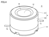
- FIG. 4 is a perspective view of the holder H.
- holder H includes a body 4, a plate portion 12, a base plate 51, a positive terminal T1, and a negative terminal T2.
- the body 4 is placed on the base plate 51.
- the body 4 includes a cylindrical cell body 42 and a window body 41 disposed on the cell body 42.
- the body 4 has a sample chamber formed therein in which the battery B is placed.
- a window W is formed between the sample chamber and the excitation source 120 in the window body 41 .
- a plate portion 12 is arranged in the window W.
- the body 4 and the base plate 51 are made of metal.
- the body 4 and the base plate 51 are made of stainless steel.
- the positive terminal T1 and the negative terminal T2 are each connected to the charging/discharging device 170.
- Battery B is charged and discharged by the charging/discharging device 170 via the positive terminal T1 and the negative terminal T2.
- the positive electrode terminal T1 is a part that electrically connects the positive electrode of the battery B installed in the holder H and the charging/discharging device 170.
- the positive electrode terminal T1 is a metal bar-shaped or plate-shaped terminal connected to the cell body 42.
- the positive electrode terminal T1 may be configured integrally with the cell body 42, for example. In this way, the positive electrode terminal T1 and the cell body 42 are stably connected. Further, for example, the positive electrode terminal T1 may be configured to be detachable from the cell body 42. With this configuration, when battery B does not need to be connected to charging/discharging device 170, positive terminal T1 can be removed from cell body 42. Therefore, the side surface of battery B has a simple cylindrical shape. Therefore, it does not get in the way when rotating battery B, for example.
- the configuration of the positive electrode terminal T1 is not limited to the above example; for example, the positive electrode terminal T1 is a portion ( For example, body 4) is included.
- the negative electrode terminal T2 is a part that electrically connects the negative electrode of the battery B installed in the holder H and the charging/discharging device 170.
- the negative electrode terminal T2 is a metal rod-shaped or plate-shaped terminal connected to the base plate 51.
- the negative electrode terminal T2 may be configured integrally with the base plate 51, for example. In this way, the negative electrode terminal T2 and the base plate 51 are stably connected. Further, for example, the negative terminal T2 may be configured to be removable from the base plate 51. With this configuration, the negative electrode terminal T2 can be removed from the base plate 51 when the battery B does not need to be connected to the charging/discharging device 170. Therefore, the side surface of battery B has a simple cylindrical shape.
- the configuration of the negative electrode terminal T2 is not limited to the above example, and for example, the negative electrode terminal T2 is connected between the negative electrode of the battery B and a rod-shaped terminal that is electrically connected to the charging/discharging device 170 and removable to the holder H. (for example, the base plate 51).
- FIG. 5 is a cross-sectional view showing an example of the internal configuration of the holder H and the configuration of the battery B.
- Holder H further includes an insulating plate 50, an insulating spacer 52, an inner cylinder 53, an electrode guide 54, a spring 55, an electrode support part 56, and a conductive member 3.
- a sample chamber R is formed inside the holder H.
- the sample chamber R is a space surrounded by the conductive member 3, the electrode guide 54, and the electrode support part 56.
- a battery B is placed in the sample chamber R.
- Battery B includes a positive electrode B1, a negative electrode B2, and a separator B3.
- battery B is a lithium ion secondary battery.
- Positive electrode B1 includes positive electrode material B11 and positive electrode current collector B12.
- the positive electrode material B11 is, for example, a single or composite metal oxide of cobalt, nickel, or manganese, or an iron phosphate-based material such as LiFePO4.
- the positive electrode current collector B12 is, for example, aluminum.
- Negative electrode B2 includes negative electrode material B21 and negative electrode current collector B22.
- the negative electrode material B21 is, for example, a carbon-based material or an alloy-based material.
- the negative electrode current collector B22 is made of copper, for example.
- Separator B3 is provided between positive electrode B1 and negative electrode B2.
- Separator B3 is, for example, a microporous membrane made of polyolefin. Since the structure, composition, and functions of each part of a lithium ion secondary battery are well known, detailed explanation will
- the insulating plate 50 is installed under the base plate 51.
- the inner cylinder 53 is installed on the base plate 51 and inside the cell body 42. Inside the inner cylinder 53, an electrode guide 54, an electrode support part 56, and a battery B arranged in the sample chamber R are installed.
- the insulating spacer 52 is installed between the base plate 51 and the cell body 42 and electrically insulates the base plate 51 and the cell body 42.
- the insulating plate 50, inner cylinder 53, and insulating spacer 52 are made of electrically insulating material.
- the insulating plate 50, the inner cylinder 53, and the insulating spacer 52 are made of polyphenylene sulfide (PPS), for example.
- the electrode guide 54 holds a spring 55.
- the spring 55 generates a pressing force when the electrode support part 56 is pressed from above.
- the electrode support part 56 is arranged on the spring 55 and transmits the pressing force of the spring 55 to the battery B.
- the negative electrode B2 of the battery B comes into close contact with the electrode support portion 56.
- the positive electrode B1 of the battery B is in close contact with the conductive member 3.
- the electrode support portion 56 and the spring 55 are made of a conductive material.
- the electrode support portion 56 and the spring 55 are made of stainless steel, for example.
- the electrode guide 54 is made of PPS, for example.
- the negative electrode B2 of the battery B is electrically connected to the negative electrode terminal T2 via the electrode support portion 56, the spring 55, and the base plate 51, as shown by the arrow AR2.
- the conductive member 3 is provided between the positive electrode B1 of battery B and the plate portion 12 so as to be in contact with the positive electrode B1 of battery B.
- the conductive member 3 is made of a conductive material. With this configuration, the positive electrode B1 of the battery B is electrically connected to the positive terminal T1 via the conductive member 3 and the cell body 42, as shown by the arrow AR1.
- the window body 41, the plate portion 12, and the conductive member 3 serve as a lid for the sample chamber R.
- the window body 41, the plate part 12, and the conductive member 3 will be collectively referred to as a "lid part.” The user opens this lid and places the battery B in the sample chamber R.
- FIG. 6 is a sectional view showing an example of the structure of the holder H near the window W. Note that from FIG. 6 onward, description of the structure below the electrode support portion 56 is omitted.
- Arrow AR3 indicates an excitation line irradiated from excitation source 120 to battery B.
- Arrow AR4 indicates characteristic X-rays generated from battery B and detected by the spectrometer.
- the positive electrode material B11 of the positive electrode B1 of battery B is irradiated with an excitation ray (arrow AR3), and characteristic X-rays are generated from the positive electrode material B11 (arrow AR4).
- the plate portion 12 includes resin members 2A and 2B and a beryllium plate 1.
- the resin members 2A and 2B correspond to an example of a "first resin member”.
- the beryllium plate 1 has resin members 2A and 2B provided on its surface. Although beryllium has high X-ray transparency, it is a metal that may be harmful to the human body. Therefore, by preventing beryllium from being directly exposed to the atmosphere by the resin members 2A and 2B, the user can handle the holder H without being too concerned about the effects of beryllium on the human body. For example, the user can feel more secure when installing the battery B into the holder H for X-ray spectroscopic analysis. It is preferable that the resin members 2A and 2B are made of resin that has high X-ray transparency and is less susceptible to X-ray damage. A resin with high X-ray transparency is, for example, a low-density resin.
- a resin with little X-ray damage is a resin having a cyclic structure. If the resin members 2A, 2B are configured in this way, the X-ray transparency of the resin members 2A, 2B is high. That is, as shown by arrows AR3 and AR4, the excitation rays irradiated from the excitation source 120 and the characteristic X-rays generated from the positive electrode B1 pass through the resin members 2A and 2B. As described above, the beryllium plate 1 also has high X-ray transparency, so the excitation rays irradiated from the excitation source 120 and the characteristic X-rays generated from the positive electrode B1 also pass through the plate portion 12. That is, X-ray spectroscopic analysis is possible through the plate portion 12.
- the resin members 2A and 2B include, for example, polyimide resin.
- Polyimide resin is a sturdy resin that has high X-ray transparency, excellent mechanical strength, and excellent chemical resistance. Therefore, by providing the polyimide resin on the surface, the possibility that the beryllium plate will be exposed is reduced. In other words, handling of the plate portion 12 becomes easier.
- PTFE polytetrafluoroethylene
- the intensity of the excitation line to be irradiated, the temperature, etc., the moisture contained in the resin members 2A and 2B may cause side reactions other than cell reactions, which may adversely affect measurement accuracy.
- the resin members 2A and 2B may be made of mutually different materials.
- the resin member 2A on the upper surface side which is less likely to come into contact with the electrolytic solution, may be made of polyimide resin, and the resin member 2B on the lower surface side may be made of fluororesin.
- the resin members 2A and 2B is PEEK (polyetheretherketone).
- the total thickness of the resin members 2A and 2B in the direction perpendicular to the beryllium plate 1 (Z-axis direction) is preferably 100 ⁇ m or less.
- the X-ray transparency of the resin members 2A and 2B is sufficiently high.
- the resin members 2A and 2B are thin, they are sufficient to prevent beryllium from being exposed, so they may be, for example, films with a thickness of 12.5 ⁇ m, which is the thinnest commercially available film. That is, the thickness of the resin members 2A and 2B may be determined in consideration of X-ray transparency and ease of handling by the manufacturer and the user.
- the conductive member 3 is configured to include aluminum.
- Aluminum is a metal with high X-ray transparency.
- aluminum is easy to handle because there are no concerns about its effects on the human body.
- aluminum has high conductivity, electrical conduction between the positive electrode B1 and the positive terminal T1 of the battery B is also ensured. Therefore, with this configuration, battery B can be subjected to X-ray spectroscopic analysis while being held in holder H, and can also be charged and discharged. Moreover, handling of the conductive member 3 is also easy. Therefore, in this specification, unless otherwise specified, the conductive member 3 is made of aluminum.
- the conductive member 3 is configured to be deposited on the resin member 2B, for example. As described later, the conductive member 3 may be a foil member, but when the conductive member 3 is vapor-deposited and integrated with the resin member 2B, compared to the case where the conductive member 3 is separate from the resin member 2B. It is easy for users to handle. For example, when the user inserts the battery B into the sample chamber R, there is no possibility of the user accidentally dropping the conductive member 3.
- the conductive member 3 may be directly deposited on the lower surface of the beryllium plate 1.
- a configuration may be adopted in which only the resin member 2A is provided on the upper surface of the beryllium plate 1 and the resin member 2B is not provided. Even with this configuration, the lower surface of the beryllium plate 1 is not exposed, and the resin member 2B is removed, so that the X-ray transparency in the window W is increased.
- the conductive member 3 will peel off and the beryllium plate 1 will be exposed due to repeated use, it is better to deposit the conductive member 3 on the lower surface of the beryllium plate 1 on which the resin member 2B is deposited. Highly safe.
- the conductive member 3 may be formed into a film shape and placed between the positive electrode B1 of the battery B and the resin member 2B. In this case, the user needs to be careful not to drop the conductive member 3 when putting the battery B into the sample chamber R. However, on the other hand, the cost and effort of depositing the conductive member 3 on the resin member 2B during manufacturing can be omitted. The manufacturer may appropriately select whether to deposit the conductive member 3 on the resin member 2B or to form it into a film and arrange it between the conductive member 3 and the resin member 2B, considering the merits and demerits of each.
- the conductive member 3 preferably has a thickness of 0.1 ⁇ m or more and 10 ⁇ m or less. With this configuration, the X-ray transparency of the conductive member 3 is sufficiently high. Therefore, the excitation rays irradiated from the excitation source 120 and the characteristic X-rays generated from the positive electrode B1 also pass through the conductive member 3.
- the excitation line irradiated from the excitation source 120 passes through the resin members 2A, 2B, the beryllium plate 1, and the conductive member 3, and is irradiated onto the positive electrode B1 of the battery B. Furthermore, characteristic X-rays generated from the positive electrode B1 are transmitted through the conductive member 3, the resin members 2A and 2B, and the beryllium plate 1, and are detected by a spectrometer. Therefore, X-ray spectroscopic analysis of the battery material can be performed without disassembling battery B.
- the battery materials of lithium ion batteries are highly reactive with moisture and oxygen in the atmosphere. Therefore, the lithium-ion battery under development also has a metal laminated structure to prevent air from entering. Specifically, for example, the battery material is sealed with a stainless steel cell body and a stainless steel lid.
- metal laminates such as stainless steel have a large absorption of X-rays, X-ray spectroscopic analysis of battery materials cannot be performed while they are laminated. Therefore, conventionally, as shown in Patent Document 1, it has been common to disassemble a battery and take out only the positive electrode material, which is one of the battery materials, for analysis.
- the plate portion 12 including the beryllium plate 1 with the resin members 2A and 2B provided on the surface is arranged in the window W of the holder H.
- X-ray spectroscopic analysis of the battery material can be performed while the battery B is placed in the holder H. That is, it is easy to repeat and sequentially perform the X-ray spectroscopic analysis and charging/discharging of battery B. Therefore, discrete changes in battery materials during charging and discharging can be analyzed.
- the device main body 10 includes a charging/discharging device 170, it is also possible to perform X-ray spectroscopic analysis in real time while charging and discharging the battery B. In this case, continuous changes in battery materials during charging and discharging can be analyzed. Therefore, by using the holder H according to this embodiment, continuous changes in the installed battery B can be analyzed.
- the analyzer 100 performs X-ray spectroscopic analysis of the battery B based on the following process.
- FIG. 7 is a flowchart illustrating processing related to X-ray spectroscopy. The process in FIG. 7 is executed by the analysis device 100.
- the user Before performing the process shown in FIG. 7, the user first opens the lid of the holder H and installs the battery B. Subsequently, the user charges and discharges battery B using, for example, the charging and discharging device 170.
- the user When the charging/discharging device 170 is included in the device main body 10, the user first installs the holder H in the device main body 10, connects the charging/discharging device 170, and charges/discharges the battery B. On the other hand, when the charging/discharging device 170 is provided outside the device main body 10, the user first connects the holder H to the charging/discharging device 170 to charge and discharge the battery B, and then moves the holder H to the device main body 10. .
- step ST02 the processor 30 of the signal processing device 20 determines whether the user has input an instruction to start analysis using the operation unit 26. If no instruction to start analysis is input (NO in step ST02), the processor 30 repeats step ST02.
- step ST04 the excitation source 120 of the apparatus main body 10 is configured to form a sample chamber R in which the battery B is placed, according to a command from the processor 30. An excitation beam is irradiated onto the holder H.
- step ST06 the spectrometer spectrally spectra the characteristic X-rays generated by battery B and detects the intensity of each wavelength. Further, a signal indicating the intensity of each wavelength of the detected characteristic X-ray is transmitted to the signal processing device 20.
- step ST08 the processor 30 of the signal processing device 20 processes a signal indicating the intensity of each wavelength of the characteristic X-ray.
- step ST10 the processor 30 stores the processing results in the memory 32. Furthermore, the processor 30 displays the results of the process on the display 24, and ends the process.
- the analyzer 100 can perform X-ray spectroscopic analysis without disassembling the battery B installed in the holder H. Furthermore, the analysis device 100 can notify the user of the results of the X-ray spectroscopic analysis.
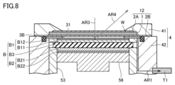
- FIG. 8 is a sectional view illustrating a first modification of the embodiment.
- an opening 31 is formed in the conductive member 3B at a position overlapping the window W.
- the shape of the opening 31 is, for example, circular or square, but is not limited thereto.
- the conductive member 3 shown in FIG. 6 has high X-ray transparency, but does not transmit all X-rays. Therefore, if the conductive member 3B is configured as shown in FIG. 8, the excitation line from the excitation source 120 passes through the opening 31 of the conductive member 3B and is irradiated onto the battery B, which is the sample. That is, the excitation line irradiated to the battery B is not attenuated by the conductive member 3B. Therefore, the strength of the excitation line becomes stronger than when the opening 31 is not formed in the conductive member 3.
- the characteristic X-rays generated in the battery B also pass through the opening 31 of the conductive member 3B and reach the spectroscope. That is, the characteristic X-rays reaching the spectroscope are not attenuated by the conductive member 3B. Therefore, the intensity of the characteristic X-rays becomes stronger than when the opening 31 is not formed in the conductive member 3.
- the thickness of the conductive member 3B is greater than when the opening 31 is not formed.
- the thickness of the conductive member 3B may be 10 ⁇ m or more.
- the conductive member 3B since there is no need to consider the attenuation of excitation rays and characteristic X-rays by the conductive member 3B, it is possible to use a material such as copper, which has lower X-ray transparency and higher conductivity than aluminum, for the conductive member 3B. can. With this configuration, the options for materials that can be used for the conductive member 3B are expanded.
- FIG. 9 is a sectional view illustrating a second modification of the embodiment.
- resin member 2C is disposed inside opening 31 of conductive member 3B.
- the resin member 2C corresponds to an example of a "second resin member”. It is preferable that the resin member 2C has the same thickness as the opening 31.
- the resin member 2C is formed in a film shape and is disposed between the positive electrode B1 and the resin member 2B.
- the resin member 2C has a size larger than the X-ray irradiation range and smaller than the opening 31, for example.
- Another example of the resin member 2C is constructed by filling the opening 31 with a paste-like resin. In this case, the resin member 2C has the same size as the opening 31, for example.
- the resin member 2C is made of resin that has high X-ray transparency and is less susceptible to X-ray damage.
- the resin member 2C is made of polyimide resin, for example.
- the holder is a holder that holds a battery that is an analysis target of X-ray analysis.
- the battery includes a positive electrode and a negative electrode.
- the holder has a sample chamber formed therein for placing the battery.
- the holder includes a body, a beryllium plate, a first resin member, a conductive member, a positive terminal, and a negative terminal.
- a window is formed on the top surface of the body. Beryllium plates are placed on the windows.
- the first resin member is provided on the surface of the beryllium plate.
- the conductive member is provided between the positive electrode and the first resin member so as to be in contact with the positive electrode of the battery.
- the positive terminal is electrically connected to the conductive member.
- the negative electrode terminal is electrically connected to the negative electrode.
- X-ray spectroscopic analysis of the battery can be performed by irradiating the battery material with X-rays through the beryllium plate placed in the window of the holder. Therefore, battery materials can be analyzed without disassembling the battery.
- the first resin member may include polyimide resin.
- Polyimide resin has high X-ray transparency. That is, according to the holder described in item 2, it is easy to perform X-ray spectroscopic analysis of the battery through the plate portion made of the first resin member and the beryllium plate. Furthermore, polyimide resin is a sturdy resin that has excellent mechanical strength and excellent chemical resistance. Therefore, by providing a resin member containing polyimide resin on the surface, it is possible to reduce the possibility that the beryllium plate will be exposed. That is, according to the holder described in item 2, the plate portion can be easily handled.
- the first resin member may include a fluororesin.
- the intensity of the irradiated excitation line, the temperature, etc., the moisture contained in the first resin member may cause side reactions other than cell reactions, which may adversely affect measurement accuracy. Therefore, according to the holder described in item 3, this problem can be suppressed by using a highly water-repellent fluororesin as the first resin member.
- the total thickness of the first resin member in the direction perpendicular to the beryllium plate may be 100 ⁇ m or less.
- the first resin member has sufficiently high X-ray transparency.
- the conductive member may include aluminum.
- Aluminum is a metal with the second highest X-ray transparency after beryllium. On the other hand, aluminum is easier to handle than beryllium because it is less likely to affect the human body. According to the holder described in item 5, X-ray spectroscopic analysis is possible while the battery is placed in the holder. Moreover, handling of the conductive member is also easy.
- the conductive member may have a thickness of 0.1 ⁇ m or more and 10 ⁇ m or less.
- the conductive member has sufficiently high X-ray transparency.
- the conductive member may be deposited on the first resin member.
- the holder is easier for the user to handle than when the conductive member is separate from the first resin member.
- the conductive member is formed in a film shape and may be disposed between the positive electrode and the first resin member.
- the cost and effort of depositing the conductive member on the first resin member during manufacturing can be omitted.
- an opening may be formed in the conductive member at a position overlapping the window.
- the holder may further include a second resin member, and the second resin member may be disposed inside the opening.
- the holder described in Item 10 it is possible to prevent deformation such as distortion from occurring in the part of the battery corresponding to the opening due to the pressing force exerted from below by the spring on the battery, by preventing the second resin member, which is the inclusion, from deforming the battery. This can be prevented by physical interference.
- An analysis device includes a holder, a spectrometer, and a signal processing device.
- the holder holds the battery.
- the spectrometer irradiates the battery held in the holder with excitation rays, spectrally spectra the generated characteristic X-rays, and detects the intensity of each wavelength.
- the signal processing device processes the signal output from the spectrometer.
- the battery includes a positive electrode and a negative electrode.
- the holder includes a body, a beryllium plate, a resin member, a conductive member, a positive terminal, and a negative terminal.
- the body has a sample chamber formed therein for arranging the battery, and a window formed in the direction of incidence of the excitation line.
- Beryllium plates are placed on the windows.
- the resin member is provided on the surface of the beryllium plate.
- the conductive member is provided between the positive electrode and the resin member so as to be in contact with the positive electrode.
- the positive terminal is electrically connected to the conductive member.
- the negative electrode terminal is electrically connected to the negative electrode.
- X-ray spectroscopic analysis of the battery can be performed by irradiating the battery material with X-rays through the beryllium plate placed in the window of the holder. Therefore, battery materials can be analyzed without disassembling the battery.
- An analysis method is a battery analysis method, which includes the steps of irradiating the battery held in a holder with an excitation ray, and spectroscopy of characteristic X-rays generated from the battery to determine the wavelength of the battery. and a step of processing a signal indicating the intensity of each wavelength of characteristic X-rays.
- the battery includes a positive electrode and a negative electrode.
- the holder includes a body, a beryllium plate, a resin member, a conductive member, a positive terminal, and a negative terminal.
- the body has a sample chamber formed therein for arranging the battery, and a window formed in the direction of incidence of the excitation line. Beryllium plates are placed on the windows.
- the resin member is provided on the surface of the beryllium plate.
- the conductive member is provided between the positive electrode and the resin member so as to be in contact with the positive electrode.
- the positive terminal is electrically connected to a conductive member.
- the negative electrode terminal is electrically connected to the negative electrode.
- X-ray spectroscopic analysis of the battery can be performed by irradiating the battery material with X-rays through the beryllium plate placed in the window of the holder. Therefore, battery materials can be analyzed without disassembling the battery.
Landscapes
- Chemical & Material Sciences (AREA)
- Physics & Mathematics (AREA)
- Health & Medical Sciences (AREA)
- Pathology (AREA)
- Immunology (AREA)
- General Physics & Mathematics (AREA)
- General Health & Medical Sciences (AREA)
- Biochemistry (AREA)
- Analytical Chemistry (AREA)
- Life Sciences & Earth Sciences (AREA)
- Spectroscopy & Molecular Physics (AREA)
- Engineering & Computer Science (AREA)
- General Chemical & Material Sciences (AREA)
- Electrochemistry (AREA)
- Chemical Kinetics & Catalysis (AREA)
- Manufacturing & Machinery (AREA)
- Crystallography & Structural Chemistry (AREA)
- Dispersion Chemistry (AREA)
- Analysing Materials By The Use Of Radiation (AREA)
Priority Applications (2)
| Application Number | Priority Date | Filing Date | Title |
|---|---|---|---|
| JP2024514924A JP7658512B2 (ja) | 2022-04-13 | 2023-04-06 | ホルダおよびそれを備える分析装置、ならびに電池の分析方法 |
| US18/854,474 US20250244264A1 (en) | 2022-04-13 | 2023-04-06 | Holder, Analysis Apparatus Including the Same, and Battery Analysis Method |
Applications Claiming Priority (2)
| Application Number | Priority Date | Filing Date | Title |
|---|---|---|---|
| JP2022-066355 | 2022-04-13 | ||
| JP2022066355 | 2022-04-13 |
Publications (1)
| Publication Number | Publication Date |
|---|---|
| WO2023199833A1 true WO2023199833A1 (ja) | 2023-10-19 |
Family
ID=88329637
Family Applications (1)
| Application Number | Title | Priority Date | Filing Date |
|---|---|---|---|
| PCT/JP2023/014181 Ceased WO2023199833A1 (ja) | 2022-04-13 | 2023-04-06 | ホルダおよびそれを備える分析装置、ならびに電池の分析方法 |
Country Status (3)
| Country | Link |
|---|---|
| US (1) | US20250244264A1 (https=) |
| JP (1) | JP7658512B2 (https=) |
| WO (1) | WO2023199833A1 (https=) |
Families Citing this family (2)
| Publication number | Priority date | Publication date | Assignee | Title |
|---|---|---|---|---|
| USD1120783S1 (en) * | 2024-06-25 | 2026-03-31 | Rigaku Corporation | Measuring device for x-ray emission spectrochemical analysis |
| JP1784615S (ja) * | 2024-06-25 | 2024-11-14 | エックス線分析機 |
Citations (10)
| Publication number | Priority date | Publication date | Assignee | Title |
|---|---|---|---|---|
| JPS494490A (https=) * | 1972-04-24 | 1974-01-16 | ||
| JPS55143557U (https=) * | 1979-03-30 | 1980-10-15 | ||
| JPS5638862U (https=) * | 1979-08-31 | 1981-04-11 | ||
| JP2001289802A (ja) * | 2000-04-10 | 2001-10-19 | Rigaku Industrial Co | 蛍光x線分析装置及びそれに使用するx線検出器 |
| JP2005024299A (ja) * | 2003-06-30 | 2005-01-27 | Tanaka Scientific Ltd | X線分析機器用窓材 |
| JP2005024300A (ja) * | 2003-06-30 | 2005-01-27 | Tanaka Scientific Ltd | 蛍光x線分析装置のフローセル |
| JP2010038539A (ja) * | 2006-11-30 | 2010-02-18 | Sumitomo Metal Mining Co Ltd | 汚染土壌の重金属濃度測定装置及び測定方法。 |
| JP2013160614A (ja) * | 2012-02-03 | 2013-08-19 | Horiba Ltd | X線検出装置 |
| US20140093052A1 (en) * | 2012-09-28 | 2014-04-03 | Uchicago Argonne, Llc | Transmission-geometry electrochemical cell for in-situ scattering and spectroscopy investigations |
| WO2021038943A1 (ja) * | 2019-08-27 | 2021-03-04 | 株式会社リガク | 電池分析用構造体およびx線回折装置 |
Family Cites Families (3)
| Publication number | Priority date | Publication date | Assignee | Title |
|---|---|---|---|---|
| US7022290B2 (en) * | 2001-06-19 | 2006-04-04 | Rutgers, The State University | System structure for in situ x-ray study of electrochemical cell component performance |
| KR102390689B1 (ko) * | 2018-02-21 | 2022-04-26 | 가부시키가이샤 시마즈세이사쿠쇼 | 전지 재료의 화학 상태 분석 장치 및 방법 |
| JP2021189088A (ja) * | 2020-06-02 | 2021-12-13 | 株式会社島津製作所 | 分析装置および分析方法 |
-
2023
- 2023-04-06 WO PCT/JP2023/014181 patent/WO2023199833A1/ja not_active Ceased
- 2023-04-06 JP JP2024514924A patent/JP7658512B2/ja active Active
- 2023-04-06 US US18/854,474 patent/US20250244264A1/en active Pending
Patent Citations (10)
| Publication number | Priority date | Publication date | Assignee | Title |
|---|---|---|---|---|
| JPS494490A (https=) * | 1972-04-24 | 1974-01-16 | ||
| JPS55143557U (https=) * | 1979-03-30 | 1980-10-15 | ||
| JPS5638862U (https=) * | 1979-08-31 | 1981-04-11 | ||
| JP2001289802A (ja) * | 2000-04-10 | 2001-10-19 | Rigaku Industrial Co | 蛍光x線分析装置及びそれに使用するx線検出器 |
| JP2005024299A (ja) * | 2003-06-30 | 2005-01-27 | Tanaka Scientific Ltd | X線分析機器用窓材 |
| JP2005024300A (ja) * | 2003-06-30 | 2005-01-27 | Tanaka Scientific Ltd | 蛍光x線分析装置のフローセル |
| JP2010038539A (ja) * | 2006-11-30 | 2010-02-18 | Sumitomo Metal Mining Co Ltd | 汚染土壌の重金属濃度測定装置及び測定方法。 |
| JP2013160614A (ja) * | 2012-02-03 | 2013-08-19 | Horiba Ltd | X線検出装置 |
| US20140093052A1 (en) * | 2012-09-28 | 2014-04-03 | Uchicago Argonne, Llc | Transmission-geometry electrochemical cell for in-situ scattering and spectroscopy investigations |
| WO2021038943A1 (ja) * | 2019-08-27 | 2021-03-04 | 株式会社リガク | 電池分析用構造体およびx線回折装置 |
Non-Patent Citations (1)
| Title |
|---|
| ANONYMOUS: "BL20XU Medical Imaging II", SPRING8 SACLA ANNUAL REPORT FY2013, 1 December 2014 (2014-12-01), pages 58 - 59, XP093099849 * |
Also Published As
| Publication number | Publication date |
|---|---|
| US20250244264A1 (en) | 2025-07-31 |
| JP7658512B2 (ja) | 2025-04-08 |
| JPWO2023199833A1 (https=) | 2023-10-19 |
Similar Documents
| Publication | Publication Date | Title |
|---|---|---|
| JP6860116B2 (ja) | 電池材料の化学状態分析装置及び方法 | |
| US9022652B2 (en) | Transmission-geometry electrochemical cell for in-situ scattering and spectroscopy investigations | |
| JP7658512B2 (ja) | ホルダおよびそれを備える分析装置、ならびに電池の分析方法 | |
| JP5626750B2 (ja) | 測定装置及び測定方法 | |
| Zuo et al. | Nondestructive analysis of commercial batteries | |
| Fan et al. | Operando Synchrotron X‐Ray Absorption Spectroscopy: A Key Tool for Cathode Material Studies in Next‐Generation Batteries | |
| US12080858B2 (en) | Structure for battery analysis and X-ray diffraction device | |
| JP6406077B2 (ja) | 試料ホルダーおよびx線分析方法 | |
| JP2021189088A (ja) | 分析装置および分析方法 | |
| CN113804713B (zh) | X射线分析装置以及x射线分析方法 | |
| JP6221723B2 (ja) | X線分析装置及びx線分析方法 | |
| CN110320220B (zh) | 分析材料短程有序结构和长程有序结构的装置和方法 | |
| EP3974820B1 (en) | Structure for pressurization analysis, x-ray diffraction apparatus and pressurization analysis system | |
| JP2019144123A (ja) | 電池材料の化学状態分析方法 | |
| US20150204803A1 (en) | Determining elemental concentration using compton scattering | |
| JP2024098707A (ja) | ホルダおよびそれを備える分析装置、ならびに電池の分析方法 | |
| JP7525272B2 (ja) | 測定装置および測定方法 | |
| CN109596679B (zh) | 一种现场快速检测土壤重金属含量的检测装置 | |
| JP2015232546A (ja) | X線分析用システムおよびプログラム | |
| JP5502188B2 (ja) | スタックコンポーネントの適切な序列を検証するためのシステムとその方法 | |
| WO2024219015A1 (ja) | ホルダおよび電池の分析方法 | |
| US20220214291A1 (en) | X-Ray Spectroscopic Analysis Apparatus and Elemental Analysis Method | |
| Yaroslavtsev et al. | Electrochemical cell for synchrotron nuclear resonance techniques | |
| CN107402196B (zh) | X射线荧光分析仪器及用于其的样品容器 | |
| US20240061023A1 (en) | System and method for in-situ mapping on electrode potential and thermal distribution |
Legal Events
| Date | Code | Title | Description |
|---|---|---|---|
| 121 | Ep: the epo has been informed by wipo that ep was designated in this application |
Ref document number: 23788252 Country of ref document: EP Kind code of ref document: A1 |
|
| ENP | Entry into the national phase |
Ref document number: 2024514924 Country of ref document: JP Kind code of ref document: A |
|
| WWE | Wipo information: entry into national phase |
Ref document number: 18854474 Country of ref document: US |
|
| NENP | Non-entry into the national phase |
Ref country code: DE |
|
| 122 | Ep: pct application non-entry in european phase |
Ref document number: 23788252 Country of ref document: EP Kind code of ref document: A1 |
|
| WWP | Wipo information: published in national office |
Ref document number: 18854474 Country of ref document: US |