WO2023199833A1 - ホルダおよびそれを備える分析装置、ならびに電池の分析方法 - Google Patents
ホルダおよびそれを備える分析装置、ならびに電池の分析方法 Download PDFInfo
- Publication number
- WO2023199833A1 WO2023199833A1 PCT/JP2023/014181 JP2023014181W WO2023199833A1 WO 2023199833 A1 WO2023199833 A1 WO 2023199833A1 JP 2023014181 W JP2023014181 W JP 2023014181W WO 2023199833 A1 WO2023199833 A1 WO 2023199833A1
- Authority
- WO
- WIPO (PCT)
- Prior art keywords
- battery
- holder
- conductive member
- positive electrode
- resin member
- Prior art date
Links
- 238000004458 analytical method Methods 0.000 title claims description 31
- 239000011347 resin Substances 0.000 claims abstract description 110
- 229920005989 resin Polymers 0.000 claims abstract description 110
- 229910052790 beryllium Inorganic materials 0.000 claims abstract description 56
- ATBAMAFKBVZNFJ-UHFFFAOYSA-N beryllium atom Chemical compound [Be] ATBAMAFKBVZNFJ-UHFFFAOYSA-N 0.000 claims abstract description 56
- 238000002441 X-ray diffraction Methods 0.000 claims abstract description 5
- 230000005284 excitation Effects 0.000 claims description 59
- 238000012545 processing Methods 0.000 claims description 33
- 238000004611 spectroscopical analysis Methods 0.000 claims description 31
- 238000000034 method Methods 0.000 claims description 20
- 229910052782 aluminium Inorganic materials 0.000 claims description 11
- XAGFODPZIPBFFR-UHFFFAOYSA-N aluminium Chemical compound [Al] XAGFODPZIPBFFR-UHFFFAOYSA-N 0.000 claims description 11
- 229920001721 polyimide Polymers 0.000 claims description 10
- 239000009719 polyimide resin Substances 0.000 claims description 10
- 230000001678 irradiating effect Effects 0.000 claims description 8
- 238000001228 spectrum Methods 0.000 claims description 6
- 239000000463 material Substances 0.000 description 43
- 238000007599 discharging Methods 0.000 description 29
- 239000013078 crystal Substances 0.000 description 14
- 210000005056 cell body Anatomy 0.000 description 13
- 238000001514 detection method Methods 0.000 description 13
- HBBGRARXTFLTSG-UHFFFAOYSA-N Lithium ion Chemical compound [Li+] HBBGRARXTFLTSG-UHFFFAOYSA-N 0.000 description 9
- 229910001416 lithium ion Inorganic materials 0.000 description 9
- 229910052751 metal Inorganic materials 0.000 description 9
- 239000002184 metal Substances 0.000 description 9
- 238000004891 communication Methods 0.000 description 7
- 238000012986 modification Methods 0.000 description 7
- 230000004048 modification Effects 0.000 description 7
- 239000007774 positive electrode material Substances 0.000 description 6
- 239000010935 stainless steel Substances 0.000 description 6
- 229910001220 stainless steel Inorganic materials 0.000 description 6
- 238000010586 diagram Methods 0.000 description 5
- 125000006850 spacer group Chemical group 0.000 description 5
- 238000003825 pressing Methods 0.000 description 4
- 239000000126 substance Substances 0.000 description 4
- 239000004734 Polyphenylene sulfide Substances 0.000 description 3
- 238000000441 X-ray spectroscopy Methods 0.000 description 3
- 238000011161 development Methods 0.000 description 3
- 239000007773 negative electrode material Substances 0.000 description 3
- 229920000069 polyphenylene sulfide Polymers 0.000 description 3
- RYGMFSIKBFXOCR-UHFFFAOYSA-N Copper Chemical compound [Cu] RYGMFSIKBFXOCR-UHFFFAOYSA-N 0.000 description 2
- PXHVJJICTQNCMI-UHFFFAOYSA-N Nickel Chemical compound [Ni] PXHVJJICTQNCMI-UHFFFAOYSA-N 0.000 description 2
- 239000004696 Poly ether ether ketone Substances 0.000 description 2
- 230000002411 adverse Effects 0.000 description 2
- 230000002238 attenuated effect Effects 0.000 description 2
- 210000004027 cell Anatomy 0.000 description 2
- 238000006243 chemical reaction Methods 0.000 description 2
- 239000004020 conductor Substances 0.000 description 2
- 229910052802 copper Inorganic materials 0.000 description 2
- 239000010949 copper Substances 0.000 description 2
- 238000000151 deposition Methods 0.000 description 2
- 230000006866 deterioration Effects 0.000 description 2
- 230000000694 effects Effects 0.000 description 2
- 238000004519 manufacturing process Methods 0.000 description 2
- 238000005259 measurement Methods 0.000 description 2
- 239000000203 mixture Substances 0.000 description 2
- 229920002530 polyetherether ketone Polymers 0.000 description 2
- 229920001343 polytetrafluoroethylene Polymers 0.000 description 2
- 239000004810 polytetrafluoroethylene Substances 0.000 description 2
- 230000036647 reaction Effects 0.000 description 2
- 239000005871 repellent Substances 0.000 description 2
- 238000007086 side reaction Methods 0.000 description 2
- 229910052493 LiFePO4 Inorganic materials 0.000 description 1
- 238000002083 X-ray spectrum Methods 0.000 description 1
- 238000010521 absorption reaction Methods 0.000 description 1
- 229910045601 alloy Inorganic materials 0.000 description 1
- 239000000956 alloy Substances 0.000 description 1
- QVGXLLKOCUKJST-UHFFFAOYSA-N atomic oxygen Chemical compound [O] QVGXLLKOCUKJST-UHFFFAOYSA-N 0.000 description 1
- 238000004364 calculation method Methods 0.000 description 1
- 239000003575 carbonaceous material Substances 0.000 description 1
- 229910017052 cobalt Inorganic materials 0.000 description 1
- 239000010941 cobalt Substances 0.000 description 1
- GUTLYIVDDKVIGB-UHFFFAOYSA-N cobalt atom Chemical compound [Co] GUTLYIVDDKVIGB-UHFFFAOYSA-N 0.000 description 1
- 239000002131 composite material Substances 0.000 description 1
- 125000004122 cyclic group Chemical group 0.000 description 1
- 230000001066 destructive effect Effects 0.000 description 1
- 239000006185 dispersion Substances 0.000 description 1
- 239000012777 electrically insulating material Substances 0.000 description 1
- 239000008151 electrolyte solution Substances 0.000 description 1
- 238000010894 electron beam technology Methods 0.000 description 1
- 239000011888 foil Substances 0.000 description 1
- 230000006870 function Effects 0.000 description 1
- 229910000398 iron phosphate Inorganic materials 0.000 description 1
- WBJZTOZJJYAKHQ-UHFFFAOYSA-K iron(3+) phosphate Chemical compound [Fe+3].[O-]P([O-])([O-])=O WBJZTOZJJYAKHQ-UHFFFAOYSA-K 0.000 description 1
- 239000004973 liquid crystal related substance Substances 0.000 description 1
- WPBNNNQJVZRUHP-UHFFFAOYSA-L manganese(2+);methyl n-[[2-(methoxycarbonylcarbamothioylamino)phenyl]carbamothioyl]carbamate;n-[2-(sulfidocarbothioylamino)ethyl]carbamodithioate Chemical compound [Mn+2].[S-]C(=S)NCCNC([S-])=S.COC(=O)NC(=S)NC1=CC=CC=C1NC(=S)NC(=O)OC WPBNNNQJVZRUHP-UHFFFAOYSA-L 0.000 description 1
- 229910044991 metal oxide Inorganic materials 0.000 description 1
- 150000004706 metal oxides Chemical class 0.000 description 1
- 239000012982 microporous membrane Substances 0.000 description 1
- 229910052759 nickel Inorganic materials 0.000 description 1
- 229910052760 oxygen Inorganic materials 0.000 description 1
- 239000001301 oxygen Substances 0.000 description 1
- 229920000098 polyolefin Polymers 0.000 description 1
- -1 polytetrafluoroethylene Polymers 0.000 description 1
- 230000005855 radiation Effects 0.000 description 1
- 238000002834 transmittance Methods 0.000 description 1
- 238000004876 x-ray fluorescence Methods 0.000 description 1
Images


Classifications
-
- G—PHYSICS
- G01—MEASURING; TESTING
- G01N—INVESTIGATING OR ANALYSING MATERIALS BY DETERMINING THEIR CHEMICAL OR PHYSICAL PROPERTIES
- G01N1/00—Sampling; Preparing specimens for investigation
- G01N1/28—Preparing specimens for investigation including physical details of (bio-)chemical methods covered elsewhere, e.g. G01N33/50, C12Q
-
- G—PHYSICS
- G01—MEASURING; TESTING
- G01N—INVESTIGATING OR ANALYSING MATERIALS BY DETERMINING THEIR CHEMICAL OR PHYSICAL PROPERTIES
- G01N23/00—Investigating or analysing materials by the use of wave or particle radiation, e.g. X-rays or neutrons, not covered by groups G01N3/00 – G01N17/00, G01N21/00 or G01N22/00
- G01N23/22—Investigating or analysing materials by the use of wave or particle radiation, e.g. X-rays or neutrons, not covered by groups G01N3/00 – G01N17/00, G01N21/00 or G01N22/00 by measuring secondary emission from the material
- G01N23/2209—Investigating or analysing materials by the use of wave or particle radiation, e.g. X-rays or neutrons, not covered by groups G01N3/00 – G01N17/00, G01N21/00 or G01N22/00 by measuring secondary emission from the material using wavelength dispersive spectroscopy [WDS]
-
- G—PHYSICS
- G01—MEASURING; TESTING
- G01N—INVESTIGATING OR ANALYSING MATERIALS BY DETERMINING THEIR CHEMICAL OR PHYSICAL PROPERTIES
- G01N23/00—Investigating or analysing materials by the use of wave or particle radiation, e.g. X-rays or neutrons, not covered by groups G01N3/00 – G01N17/00, G01N21/00 or G01N22/00
- G01N23/22—Investigating or analysing materials by the use of wave or particle radiation, e.g. X-rays or neutrons, not covered by groups G01N3/00 – G01N17/00, G01N21/00 or G01N22/00 by measuring secondary emission from the material
- G01N23/223—Investigating or analysing materials by the use of wave or particle radiation, e.g. X-rays or neutrons, not covered by groups G01N3/00 – G01N17/00, G01N21/00 or G01N22/00 by measuring secondary emission from the material by irradiating the sample with X-rays or gamma-rays and by measuring X-ray fluorescence
-
- Y—GENERAL TAGGING OF NEW TECHNOLOGICAL DEVELOPMENTS; GENERAL TAGGING OF CROSS-SECTIONAL TECHNOLOGIES SPANNING OVER SEVERAL SECTIONS OF THE IPC; TECHNICAL SUBJECTS COVERED BY FORMER USPC CROSS-REFERENCE ART COLLECTIONS [XRACs] AND DIGESTS
- Y02—TECHNOLOGIES OR APPLICATIONS FOR MITIGATION OR ADAPTATION AGAINST CLIMATE CHANGE
- Y02E—REDUCTION OF GREENHOUSE GAS [GHG] EMISSIONS, RELATED TO ENERGY GENERATION, TRANSMISSION OR DISTRIBUTION
- Y02E60/00—Enabling technologies; Technologies with a potential or indirect contribution to GHG emissions mitigation
- Y02E60/10—Energy storage using batteries
Definitions
- the present invention relates to a holder, an analysis device equipped with the same, and a battery analysis method, and more particularly relates to a battery holder for use in performing X-ray spectroscopic analysis of battery materials.
- Patent Document 1 International Publication No. 2019/163023 discloses an X-ray spectrometer that disassembles a lithium ion battery, sets battery material to be analyzed in a sample holder, and performs analysis.
- secondary batteries such as lithium-ion batteries are surrounded by a metal casing with relatively low X-ray transmittance, such as stainless steel, to protect the internal battery materials, so they cannot be used as is.
- X-ray transmittance such as stainless steel
- this method of disassembling and analyzing batteries has the problem that the analysis becomes troublesome. Another problem is that even if it is possible to analyze the state of the battery material at a certain point during charging and discharging, it is difficult to analyze continuous changes in the battery material during charging and discharging. Therefore, there has been a long-awaited means for performing X-ray spectroscopic analysis of battery materials without disassembling the battery.
- the present disclosure has been made to solve such problems, and its purpose is to provide a holder that allows X-ray spectroscopic analysis of battery materials to be performed without disassembling the battery.
- a first aspect of the present invention relates to a holder that holds a battery that is an object of X-ray analysis.
- the battery includes a positive electrode and a negative electrode.
- the holder has a sample chamber formed therein for placing the battery.
- the holder includes a body, a beryllium plate, a first resin member, a conductive member, a positive terminal, and a negative terminal.
- a window is formed on the top surface of the body. Beryllium plates are placed on the windows.
- the first resin member is provided on the surface of the beryllium plate.
- the conductive member is provided between the positive electrode and the first resin member so as to be in contact with the positive electrode of the battery.
- the positive terminal is electrically connected to the conductive member.
- the negative electrode terminal is electrically connected to the negative electrode.
- a second aspect of the invention relates to a battery analysis device.
- the analysis device includes a holder, a spectrometer, and a signal processing device.
- the holder holds the battery.
- the spectrometer irradiates a battery held in a holder with excitation rays, spectrally spectra the generated characteristic X-rays, and detects the intensity of each wavelength.
- the signal processing device processes the signal output from the spectrometer.
- the battery includes a positive electrode and a negative electrode.
- the holder includes a body, a beryllium plate, a resin member, a conductive member, a positive terminal, and a negative terminal.
- the body has a sample chamber formed therein for arranging the battery, and a window formed in the direction of incidence of the excitation line. Beryllium plates are placed on the windows.
- the resin member is provided on the surface of the beryllium plate.
- the conductive member is provided between the positive electrode and the resin member so as to be in contact with the positive electrode.
- the positive terminal is electrically connected to the conductive member.
- the negative electrode terminal is electrically connected to the negative electrode.
- a third aspect of the invention is a battery analysis method, which includes the steps of irradiating the battery held in a holder with excitation rays, and spectroscopy of characteristic X-rays generated from the battery to detect the intensity of each wavelength. and processing a signal indicating the intensity of each wavelength of the characteristic X-ray.
- the battery includes a positive electrode and a negative electrode.
- the holder includes a body, a beryllium plate, a resin member, a conductive member, a positive terminal, and a negative terminal.
- the body has a sample chamber formed therein for arranging the battery, and a window formed in the direction of incidence of the excitation line. Beryllium plates are placed on the windows.
- the resin member is provided on the surface of the beryllium plate.
- the conductive member is provided between the positive electrode and the resin member so as to be in contact with the positive electrode.
- the positive terminal is electrically connected to a conductive member.
- the negative electrode terminal is electrically connected to
- X-ray spectroscopic analysis of the battery can be performed by irradiating the battery material with X-rays through the beryllium plate placed in the window of the holder. Therefore, battery materials can be analyzed without disassembling the battery.
- FIG. 1 is a schematic diagram showing the configuration of an analysis device 100 according to an embodiment of the present invention.
- FIG. 2 is a diagram schematically showing the internal configuration of the device main body.
- FIG. 2 is a diagram schematically showing the internal configuration of the device main body. It is a perspective view of a holder.
- FIG. 3 is a cross-sectional view showing an example of the internal configuration of the holder.
- FIG. 3 is a cross-sectional view showing an example of the configuration near the window of the holder. It is a flowchart explaining the processing regarding X-ray spectroscopy. It is a sectional view explaining the 1st modification of an embodiment. It is a sectional view explaining the 2nd modification of an embodiment.
- FIG. 1 is a schematic diagram showing the configuration of an analysis device 100 according to an embodiment of the present invention.
- Analyzer 100 according to this embodiment is an X-ray spectrometer equipped with a wavelength dispersive spectrometer.
- a wavelength-dispersive X-ray fluorescence analyzer will be described as an example of the X-ray spectrometer according to this embodiment.
- the "wavelength dispersion type" is a method in which characteristic X-rays are separated by a spectroscopic element, and the characteristic X-ray intensity for each target wavelength is measured to detect a characteristic X-ray spectrum.
- analysis device 100 includes a device main body 10 and a signal processing device 20.
- the apparatus main body 10 is configured to irradiate a sample with excitation rays and detect characteristic X-rays generated from the sample.
- the sample is a battery with a simple configuration held in a holder.
- the excitation line is typically an X-ray. Characteristic X-rays and fluorescent X-rays are synonymous.
- a detection signal corresponding to the characteristic X-rays detected by the apparatus main body 10 is transmitted to the signal processing apparatus 20.
- the signal processing device 20 includes a controller 22, a display 24, and an operation section 26.
- the signal processing device 20 controls the operation of the device main body 10. Further, the signal processing device 20 is configured to process the detection signal transmitted from the device main body 10 and display the results based on the analysis on the display 24.
- a display 24 and an operation unit 26 are connected to the controller 22.
- the display 24 is composed of, for example, a liquid crystal panel that can display images.
- the operation unit 26 receives user operation inputs to the analysis device 100.
- the operation unit 26 typically includes a touch panel, a keyboard, a mouse, and the like.
- the controller 22 has a processor 30, a memory 32, a communication interface (I/F) 34, and an input/output I/F 36 as main components. These units are communicably connected to each other via a bus.
- the processor 30 is typically an arithmetic processing unit such as a CPU (Central Processing Unit) or an MPU (Micro Processing Unit).
- the processor 30 controls the operation of the analysis device 100 by reading and executing a program stored in the memory 32.
- processor 30 realizes processing including detection of characteristic X-rays generated from battery B and analysis of detected characteristic X-ray data by executing the program.
- FIG. 1 illustrates a configuration in which there is a single processor, the controller 22 may have a configuration in which it has a plurality of processors.
- the memory 32 is realized by nonvolatile memory such as RAM (Random Access Memory), ROM (Read Only Memory), and flash memory.
- the memory 32 stores programs executed by the processor 30, data used by the processor 30, and the like.
- the input/output I/F 36 is an interface for exchanging various data between the processor 30, the display 24, and the operation unit 26.
- the communication I/F 34 is a communication interface for exchanging various data with the device main body 10, and is realized by an adapter, a connector, or the like.
- the communication method may be a wireless communication method using a wireless LAN (Local Area Network) or the like, or a wired communication method using a USB (Universal Serial Bus) or the like.
- the device main body 10 includes a holder H holding a battery B, an excitation source 120, a slit 130, a spectroscopic crystal 140, and a detector 150.
- the surface of the holder H on which the battery B is held is the XY plane, and the irradiation direction of the excitation line from the excitation source 120 is the Z-axis direction.
- “upper” refers to the positive direction of the Z-axis
- “lower” refers to the negative direction of the Z-axis.
- Spectroscopic crystal 140 and detector 150 constitute a "spectroscope" in the present disclosure.
- the excitation source 120 is an X-ray source that irradiates battery B with X-rays that are excitation light (excitation rays).
- an electron beam source may be used instead of an X-ray source.
- Excitation light emitted from excitation source 120 is irradiated onto battery B.
- the excitation light is irradiated perpendicularly to the surface of the battery B, but the excitation light may be irradiated at an oblique angle to the surface of the battery B.
- a specific crystal plane is parallel to the surface of the crystal. Only specific crystal planes can be used to detect characteristic X-rays. This can prevent characteristic X-rays reflected by Bragg from other crystal planes from being erroneously detected.
- the detector 150 includes a plurality of detection elements 151.
- Each of the plurality of detection elements 151 extends in the Y-axis direction.
- FIG. 2 when battery B is irradiated with excitation radiation from excitation source 120, characteristic X-rays are emitted from battery B.
- the characteristic X-rays emitted have different wavelengths depending on the material that constitutes battery B.
- an excitation line emitted from an excitation source 120 is applied to a region from position A1 to position A2.
- the characteristic X-rays emitted from the region pass through the slit 130 and reach the spectroscopic crystal 140.
- characteristic X-rays occurring at positions A1 and A2 are illustrated by broken lines.
- Position A2 is a position in the positive direction of position A1 in the X-axis direction.
- Position A1 and position A2 each extend in the Y-axis direction (see FIG. 3).
- the characteristic X-rays emitted from the battery B pass through the slit 130 and are irradiated onto the spectroscopic crystal 140.
- the angle of incidence of the characteristic X-rays on the spectroscopic crystal 140 differs depending on the generation position of the characteristic X-rays in the battery B.
- the characteristic X-rays incident on the spectroscopic crystal 140 from the battery B only the characteristic X-rays having a wavelength that satisfies the conditions for Bragg reflection are diffracted by the spectroscopic crystal 140 and reach the detector 150.
- the characteristic X-rays diffracted by the spectroscopic crystal 140 are emitted at the same angle as the incident angle. Therefore, the Bragg-reflected characteristic X-ray is detected by the detection element 151 arranged at a position corresponding to the emission angle among the plurality of detection elements 151. In this way, characteristic X-rays of wavelengths satisfying the Bragg condition at different diffraction angles are detected for each of the plurality of detection elements. In other words, by knowing the detection element that detected the characteristic X-ray, the wavelength included in the characteristic X-ray can be recognized. On the other hand, the wavelength of characteristic X-rays differs depending on the substance. Therefore, by specifying the detection element from which the characteristic X-ray was detected in the detector 150, the substance contained in the battery B to be analyzed can be specified.
- the spectrometer of the device main body 10 spectrally spectra the characteristic X-rays generated by the battery B irradiated with the excitation rays and detects the intensity of each wavelength.
- the apparatus main body 10 transmits the intensity of each detection element (the intensity of each of a plurality of detection elements) to the signal processing apparatus 20.
- the signal processing device 20 can acquire a plurality of wavelengths and the intensity of characteristic X-rays corresponding to each of the plurality of wavelengths.
- the signal processing device 20 obtains the energy and the intensity of the characteristic X-ray corresponding to the energy.
- the signal processing device 20 measures the energy at which the intensity of the characteristic X-ray reaches its peak (hereinafter referred to as "peak energy").
- the spectrometer in the device main body 10 spectrally spectra the characteristic X-rays generated by the battery B irradiated with the excitation rays and detects the intensity of each wavelength. Further, the signal processing device 20 processes signals output from the device main body 10. Therefore, the analyzer 100 can perform X-ray spectroscopic analysis of the state of the battery B.
- the device main body 10 may include a charging/discharging device 170.
- the charging/discharging device 170 is controlled by the processor 30 of the signal processing device 20.
- the charging and discharging device 170 controls charging and discharging of the battery B.
- the charging and discharging device 170 only needs to be able to control charging and discharging of the battery B, and may be a device that is independent of the device main body 10.
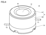
- FIG. 4 is a perspective view of the holder H.
- holder H includes a body 4, a plate portion 12, a base plate 51, a positive terminal T1, and a negative terminal T2.
- the body 4 is placed on the base plate 51.
- the body 4 includes a cylindrical cell body 42 and a window body 41 disposed on the cell body 42.
- the body 4 has a sample chamber formed therein in which the battery B is placed.
- a window W is formed between the sample chamber and the excitation source 120 in the window body 41 .
- a plate portion 12 is arranged in the window W.
- the body 4 and the base plate 51 are made of metal.
- the body 4 and the base plate 51 are made of stainless steel.
- the positive terminal T1 and the negative terminal T2 are each connected to the charging/discharging device 170.
- Battery B is charged and discharged by the charging/discharging device 170 via the positive terminal T1 and the negative terminal T2.
- the positive electrode terminal T1 is a part that electrically connects the positive electrode of the battery B installed in the holder H and the charging/discharging device 170.
- the positive electrode terminal T1 is a metal bar-shaped or plate-shaped terminal connected to the cell body 42.
- the positive electrode terminal T1 may be configured integrally with the cell body 42, for example. In this way, the positive electrode terminal T1 and the cell body 42 are stably connected. Further, for example, the positive electrode terminal T1 may be configured to be detachable from the cell body 42. With this configuration, when battery B does not need to be connected to charging/discharging device 170, positive terminal T1 can be removed from cell body 42. Therefore, the side surface of battery B has a simple cylindrical shape. Therefore, it does not get in the way when rotating battery B, for example.
- the configuration of the positive electrode terminal T1 is not limited to the above example; for example, the positive electrode terminal T1 is a portion ( For example, body 4) is included.
- the negative electrode terminal T2 is a part that electrically connects the negative electrode of the battery B installed in the holder H and the charging/discharging device 170.
- the negative electrode terminal T2 is a metal rod-shaped or plate-shaped terminal connected to the base plate 51.
- the negative electrode terminal T2 may be configured integrally with the base plate 51, for example. In this way, the negative electrode terminal T2 and the base plate 51 are stably connected. Further, for example, the negative terminal T2 may be configured to be removable from the base plate 51. With this configuration, the negative electrode terminal T2 can be removed from the base plate 51 when the battery B does not need to be connected to the charging/discharging device 170. Therefore, the side surface of battery B has a simple cylindrical shape.
- the configuration of the negative electrode terminal T2 is not limited to the above example, and for example, the negative electrode terminal T2 is connected between the negative electrode of the battery B and a rod-shaped terminal that is electrically connected to the charging/discharging device 170 and removable to the holder H. (for example, the base plate 51).
- FIG. 5 is a cross-sectional view showing an example of the internal configuration of the holder H and the configuration of the battery B.
- Holder H further includes an insulating plate 50, an insulating spacer 52, an inner cylinder 53, an electrode guide 54, a spring 55, an electrode support part 56, and a conductive member 3.
- a sample chamber R is formed inside the holder H.
- the sample chamber R is a space surrounded by the conductive member 3, the electrode guide 54, and the electrode support part 56.
- a battery B is placed in the sample chamber R.
- Battery B includes a positive electrode B1, a negative electrode B2, and a separator B3.
- battery B is a lithium ion secondary battery.
- Positive electrode B1 includes positive electrode material B11 and positive electrode current collector B12.
- the positive electrode material B11 is, for example, a single or composite metal oxide of cobalt, nickel, or manganese, or an iron phosphate-based material such as LiFePO4.
- the positive electrode current collector B12 is, for example, aluminum.
- Negative electrode B2 includes negative electrode material B21 and negative electrode current collector B22.
- the negative electrode material B21 is, for example, a carbon-based material or an alloy-based material.
- the negative electrode current collector B22 is made of copper, for example.
- Separator B3 is provided between positive electrode B1 and negative electrode B2.
- Separator B3 is, for example, a microporous membrane made of polyolefin. Since the structure, composition, and functions of each part of a lithium ion secondary battery are well known, detailed explanation will
- the insulating plate 50 is installed under the base plate 51.
- the inner cylinder 53 is installed on the base plate 51 and inside the cell body 42. Inside the inner cylinder 53, an electrode guide 54, an electrode support part 56, and a battery B arranged in the sample chamber R are installed.
- the insulating spacer 52 is installed between the base plate 51 and the cell body 42 and electrically insulates the base plate 51 and the cell body 42.
- the insulating plate 50, inner cylinder 53, and insulating spacer 52 are made of electrically insulating material.
- the insulating plate 50, the inner cylinder 53, and the insulating spacer 52 are made of polyphenylene sulfide (PPS), for example.
- the electrode guide 54 holds a spring 55.
- the spring 55 generates a pressing force when the electrode support part 56 is pressed from above.
- the electrode support part 56 is arranged on the spring 55 and transmits the pressing force of the spring 55 to the battery B.
- the negative electrode B2 of the battery B comes into close contact with the electrode support portion 56.
- the positive electrode B1 of the battery B is in close contact with the conductive member 3.
- the electrode support portion 56 and the spring 55 are made of a conductive material.
- the electrode support portion 56 and the spring 55 are made of stainless steel, for example.
- the electrode guide 54 is made of PPS, for example.
- the negative electrode B2 of the battery B is electrically connected to the negative electrode terminal T2 via the electrode support portion 56, the spring 55, and the base plate 51, as shown by the arrow AR2.
- the conductive member 3 is provided between the positive electrode B1 of battery B and the plate portion 12 so as to be in contact with the positive electrode B1 of battery B.
- the conductive member 3 is made of a conductive material. With this configuration, the positive electrode B1 of the battery B is electrically connected to the positive terminal T1 via the conductive member 3 and the cell body 42, as shown by the arrow AR1.
- the window body 41, the plate portion 12, and the conductive member 3 serve as a lid for the sample chamber R.
- the window body 41, the plate part 12, and the conductive member 3 will be collectively referred to as a "lid part.” The user opens this lid and places the battery B in the sample chamber R.
- FIG. 6 is a sectional view showing an example of the structure of the holder H near the window W. Note that from FIG. 6 onward, description of the structure below the electrode support portion 56 is omitted.
- Arrow AR3 indicates an excitation line irradiated from excitation source 120 to battery B.
- Arrow AR4 indicates characteristic X-rays generated from battery B and detected by the spectrometer.
- the positive electrode material B11 of the positive electrode B1 of battery B is irradiated with an excitation ray (arrow AR3), and characteristic X-rays are generated from the positive electrode material B11 (arrow AR4).
- the plate portion 12 includes resin members 2A and 2B and a beryllium plate 1.
- the resin members 2A and 2B correspond to an example of a "first resin member”.
- the beryllium plate 1 has resin members 2A and 2B provided on its surface. Although beryllium has high X-ray transparency, it is a metal that may be harmful to the human body. Therefore, by preventing beryllium from being directly exposed to the atmosphere by the resin members 2A and 2B, the user can handle the holder H without being too concerned about the effects of beryllium on the human body. For example, the user can feel more secure when installing the battery B into the holder H for X-ray spectroscopic analysis. It is preferable that the resin members 2A and 2B are made of resin that has high X-ray transparency and is less susceptible to X-ray damage. A resin with high X-ray transparency is, for example, a low-density resin.
- a resin with little X-ray damage is a resin having a cyclic structure. If the resin members 2A, 2B are configured in this way, the X-ray transparency of the resin members 2A, 2B is high. That is, as shown by arrows AR3 and AR4, the excitation rays irradiated from the excitation source 120 and the characteristic X-rays generated from the positive electrode B1 pass through the resin members 2A and 2B. As described above, the beryllium plate 1 also has high X-ray transparency, so the excitation rays irradiated from the excitation source 120 and the characteristic X-rays generated from the positive electrode B1 also pass through the plate portion 12. That is, X-ray spectroscopic analysis is possible through the plate portion 12.
- the resin members 2A and 2B include, for example, polyimide resin.
- Polyimide resin is a sturdy resin that has high X-ray transparency, excellent mechanical strength, and excellent chemical resistance. Therefore, by providing the polyimide resin on the surface, the possibility that the beryllium plate will be exposed is reduced. In other words, handling of the plate portion 12 becomes easier.
- PTFE polytetrafluoroethylene
- the intensity of the excitation line to be irradiated, the temperature, etc., the moisture contained in the resin members 2A and 2B may cause side reactions other than cell reactions, which may adversely affect measurement accuracy.
- the resin members 2A and 2B may be made of mutually different materials.
- the resin member 2A on the upper surface side which is less likely to come into contact with the electrolytic solution, may be made of polyimide resin, and the resin member 2B on the lower surface side may be made of fluororesin.
- the resin members 2A and 2B is PEEK (polyetheretherketone).
- the total thickness of the resin members 2A and 2B in the direction perpendicular to the beryllium plate 1 (Z-axis direction) is preferably 100 ⁇ m or less.
- the X-ray transparency of the resin members 2A and 2B is sufficiently high.
- the resin members 2A and 2B are thin, they are sufficient to prevent beryllium from being exposed, so they may be, for example, films with a thickness of 12.5 ⁇ m, which is the thinnest commercially available film. That is, the thickness of the resin members 2A and 2B may be determined in consideration of X-ray transparency and ease of handling by the manufacturer and the user.
- the conductive member 3 is configured to include aluminum.
- Aluminum is a metal with high X-ray transparency.
- aluminum is easy to handle because there are no concerns about its effects on the human body.
- aluminum has high conductivity, electrical conduction between the positive electrode B1 and the positive terminal T1 of the battery B is also ensured. Therefore, with this configuration, battery B can be subjected to X-ray spectroscopic analysis while being held in holder H, and can also be charged and discharged. Moreover, handling of the conductive member 3 is also easy. Therefore, in this specification, unless otherwise specified, the conductive member 3 is made of aluminum.
- the conductive member 3 is configured to be deposited on the resin member 2B, for example. As described later, the conductive member 3 may be a foil member, but when the conductive member 3 is vapor-deposited and integrated with the resin member 2B, compared to the case where the conductive member 3 is separate from the resin member 2B. It is easy for users to handle. For example, when the user inserts the battery B into the sample chamber R, there is no possibility of the user accidentally dropping the conductive member 3.
- the conductive member 3 may be directly deposited on the lower surface of the beryllium plate 1.
- a configuration may be adopted in which only the resin member 2A is provided on the upper surface of the beryllium plate 1 and the resin member 2B is not provided. Even with this configuration, the lower surface of the beryllium plate 1 is not exposed, and the resin member 2B is removed, so that the X-ray transparency in the window W is increased.
- the conductive member 3 will peel off and the beryllium plate 1 will be exposed due to repeated use, it is better to deposit the conductive member 3 on the lower surface of the beryllium plate 1 on which the resin member 2B is deposited. Highly safe.
- the conductive member 3 may be formed into a film shape and placed between the positive electrode B1 of the battery B and the resin member 2B. In this case, the user needs to be careful not to drop the conductive member 3 when putting the battery B into the sample chamber R. However, on the other hand, the cost and effort of depositing the conductive member 3 on the resin member 2B during manufacturing can be omitted. The manufacturer may appropriately select whether to deposit the conductive member 3 on the resin member 2B or to form it into a film and arrange it between the conductive member 3 and the resin member 2B, considering the merits and demerits of each.
- the conductive member 3 preferably has a thickness of 0.1 ⁇ m or more and 10 ⁇ m or less. With this configuration, the X-ray transparency of the conductive member 3 is sufficiently high. Therefore, the excitation rays irradiated from the excitation source 120 and the characteristic X-rays generated from the positive electrode B1 also pass through the conductive member 3.
- the excitation line irradiated from the excitation source 120 passes through the resin members 2A, 2B, the beryllium plate 1, and the conductive member 3, and is irradiated onto the positive electrode B1 of the battery B. Furthermore, characteristic X-rays generated from the positive electrode B1 are transmitted through the conductive member 3, the resin members 2A and 2B, and the beryllium plate 1, and are detected by a spectrometer. Therefore, X-ray spectroscopic analysis of the battery material can be performed without disassembling battery B.
- the battery materials of lithium ion batteries are highly reactive with moisture and oxygen in the atmosphere. Therefore, the lithium-ion battery under development also has a metal laminated structure to prevent air from entering. Specifically, for example, the battery material is sealed with a stainless steel cell body and a stainless steel lid.
- metal laminates such as stainless steel have a large absorption of X-rays, X-ray spectroscopic analysis of battery materials cannot be performed while they are laminated. Therefore, conventionally, as shown in Patent Document 1, it has been common to disassemble a battery and take out only the positive electrode material, which is one of the battery materials, for analysis.
- the plate portion 12 including the beryllium plate 1 with the resin members 2A and 2B provided on the surface is arranged in the window W of the holder H.
- X-ray spectroscopic analysis of the battery material can be performed while the battery B is placed in the holder H. That is, it is easy to repeat and sequentially perform the X-ray spectroscopic analysis and charging/discharging of battery B. Therefore, discrete changes in battery materials during charging and discharging can be analyzed.
- the device main body 10 includes a charging/discharging device 170, it is also possible to perform X-ray spectroscopic analysis in real time while charging and discharging the battery B. In this case, continuous changes in battery materials during charging and discharging can be analyzed. Therefore, by using the holder H according to this embodiment, continuous changes in the installed battery B can be analyzed.
- the analyzer 100 performs X-ray spectroscopic analysis of the battery B based on the following process.
- FIG. 7 is a flowchart illustrating processing related to X-ray spectroscopy. The process in FIG. 7 is executed by the analysis device 100.
- the user Before performing the process shown in FIG. 7, the user first opens the lid of the holder H and installs the battery B. Subsequently, the user charges and discharges battery B using, for example, the charging and discharging device 170.
- the user When the charging/discharging device 170 is included in the device main body 10, the user first installs the holder H in the device main body 10, connects the charging/discharging device 170, and charges/discharges the battery B. On the other hand, when the charging/discharging device 170 is provided outside the device main body 10, the user first connects the holder H to the charging/discharging device 170 to charge and discharge the battery B, and then moves the holder H to the device main body 10. .
- step ST02 the processor 30 of the signal processing device 20 determines whether the user has input an instruction to start analysis using the operation unit 26. If no instruction to start analysis is input (NO in step ST02), the processor 30 repeats step ST02.
- step ST04 the excitation source 120 of the apparatus main body 10 is configured to form a sample chamber R in which the battery B is placed, according to a command from the processor 30. An excitation beam is irradiated onto the holder H.
- step ST06 the spectrometer spectrally spectra the characteristic X-rays generated by battery B and detects the intensity of each wavelength. Further, a signal indicating the intensity of each wavelength of the detected characteristic X-ray is transmitted to the signal processing device 20.
- step ST08 the processor 30 of the signal processing device 20 processes a signal indicating the intensity of each wavelength of the characteristic X-ray.
- step ST10 the processor 30 stores the processing results in the memory 32. Furthermore, the processor 30 displays the results of the process on the display 24, and ends the process.
- the analyzer 100 can perform X-ray spectroscopic analysis without disassembling the battery B installed in the holder H. Furthermore, the analysis device 100 can notify the user of the results of the X-ray spectroscopic analysis.
- FIG. 8 is a sectional view illustrating a first modification of the embodiment.
- an opening 31 is formed in the conductive member 3B at a position overlapping the window W.
- the shape of the opening 31 is, for example, circular or square, but is not limited thereto.
- the conductive member 3 shown in FIG. 6 has high X-ray transparency, but does not transmit all X-rays. Therefore, if the conductive member 3B is configured as shown in FIG. 8, the excitation line from the excitation source 120 passes through the opening 31 of the conductive member 3B and is irradiated onto the battery B, which is the sample. That is, the excitation line irradiated to the battery B is not attenuated by the conductive member 3B. Therefore, the strength of the excitation line becomes stronger than when the opening 31 is not formed in the conductive member 3.
- the characteristic X-rays generated in the battery B also pass through the opening 31 of the conductive member 3B and reach the spectroscope. That is, the characteristic X-rays reaching the spectroscope are not attenuated by the conductive member 3B. Therefore, the intensity of the characteristic X-rays becomes stronger than when the opening 31 is not formed in the conductive member 3.
- the thickness of the conductive member 3B is greater than when the opening 31 is not formed.
- the thickness of the conductive member 3B may be 10 ⁇ m or more.
- the conductive member 3B since there is no need to consider the attenuation of excitation rays and characteristic X-rays by the conductive member 3B, it is possible to use a material such as copper, which has lower X-ray transparency and higher conductivity than aluminum, for the conductive member 3B. can. With this configuration, the options for materials that can be used for the conductive member 3B are expanded.
- FIG. 9 is a sectional view illustrating a second modification of the embodiment.
- resin member 2C is disposed inside opening 31 of conductive member 3B.
- the resin member 2C corresponds to an example of a "second resin member”. It is preferable that the resin member 2C has the same thickness as the opening 31.
- the resin member 2C is formed in a film shape and is disposed between the positive electrode B1 and the resin member 2B.
- the resin member 2C has a size larger than the X-ray irradiation range and smaller than the opening 31, for example.
- Another example of the resin member 2C is constructed by filling the opening 31 with a paste-like resin. In this case, the resin member 2C has the same size as the opening 31, for example.
- the resin member 2C is made of resin that has high X-ray transparency and is less susceptible to X-ray damage.
- the resin member 2C is made of polyimide resin, for example.
- the holder is a holder that holds a battery that is an analysis target of X-ray analysis.
- the battery includes a positive electrode and a negative electrode.
- the holder has a sample chamber formed therein for placing the battery.
- the holder includes a body, a beryllium plate, a first resin member, a conductive member, a positive terminal, and a negative terminal.
- a window is formed on the top surface of the body. Beryllium plates are placed on the windows.
- the first resin member is provided on the surface of the beryllium plate.
- the conductive member is provided between the positive electrode and the first resin member so as to be in contact with the positive electrode of the battery.
- the positive terminal is electrically connected to the conductive member.
- the negative electrode terminal is electrically connected to the negative electrode.
- X-ray spectroscopic analysis of the battery can be performed by irradiating the battery material with X-rays through the beryllium plate placed in the window of the holder. Therefore, battery materials can be analyzed without disassembling the battery.
- the first resin member may include polyimide resin.
- Polyimide resin has high X-ray transparency. That is, according to the holder described in item 2, it is easy to perform X-ray spectroscopic analysis of the battery through the plate portion made of the first resin member and the beryllium plate. Furthermore, polyimide resin is a sturdy resin that has excellent mechanical strength and excellent chemical resistance. Therefore, by providing a resin member containing polyimide resin on the surface, it is possible to reduce the possibility that the beryllium plate will be exposed. That is, according to the holder described in item 2, the plate portion can be easily handled.
- the first resin member may include a fluororesin.
- the intensity of the irradiated excitation line, the temperature, etc., the moisture contained in the first resin member may cause side reactions other than cell reactions, which may adversely affect measurement accuracy. Therefore, according to the holder described in item 3, this problem can be suppressed by using a highly water-repellent fluororesin as the first resin member.
- the total thickness of the first resin member in the direction perpendicular to the beryllium plate may be 100 ⁇ m or less.
- the first resin member has sufficiently high X-ray transparency.
- the conductive member may include aluminum.
- Aluminum is a metal with the second highest X-ray transparency after beryllium. On the other hand, aluminum is easier to handle than beryllium because it is less likely to affect the human body. According to the holder described in item 5, X-ray spectroscopic analysis is possible while the battery is placed in the holder. Moreover, handling of the conductive member is also easy.
- the conductive member may have a thickness of 0.1 ⁇ m or more and 10 ⁇ m or less.
- the conductive member has sufficiently high X-ray transparency.
- the conductive member may be deposited on the first resin member.
- the holder is easier for the user to handle than when the conductive member is separate from the first resin member.
- the conductive member is formed in a film shape and may be disposed between the positive electrode and the first resin member.
- the cost and effort of depositing the conductive member on the first resin member during manufacturing can be omitted.
- an opening may be formed in the conductive member at a position overlapping the window.
- the holder may further include a second resin member, and the second resin member may be disposed inside the opening.
- the holder described in Item 10 it is possible to prevent deformation such as distortion from occurring in the part of the battery corresponding to the opening due to the pressing force exerted from below by the spring on the battery, by preventing the second resin member, which is the inclusion, from deforming the battery. This can be prevented by physical interference.
- An analysis device includes a holder, a spectrometer, and a signal processing device.
- the holder holds the battery.
- the spectrometer irradiates the battery held in the holder with excitation rays, spectrally spectra the generated characteristic X-rays, and detects the intensity of each wavelength.
- the signal processing device processes the signal output from the spectrometer.
- the battery includes a positive electrode and a negative electrode.
- the holder includes a body, a beryllium plate, a resin member, a conductive member, a positive terminal, and a negative terminal.
- the body has a sample chamber formed therein for arranging the battery, and a window formed in the direction of incidence of the excitation line.
- Beryllium plates are placed on the windows.
- the resin member is provided on the surface of the beryllium plate.
- the conductive member is provided between the positive electrode and the resin member so as to be in contact with the positive electrode.
- the positive terminal is electrically connected to the conductive member.
- the negative electrode terminal is electrically connected to the negative electrode.
- X-ray spectroscopic analysis of the battery can be performed by irradiating the battery material with X-rays through the beryllium plate placed in the window of the holder. Therefore, battery materials can be analyzed without disassembling the battery.
- An analysis method is a battery analysis method, which includes the steps of irradiating the battery held in a holder with an excitation ray, and spectroscopy of characteristic X-rays generated from the battery to determine the wavelength of the battery. and a step of processing a signal indicating the intensity of each wavelength of characteristic X-rays.
- the battery includes a positive electrode and a negative electrode.
- the holder includes a body, a beryllium plate, a resin member, a conductive member, a positive terminal, and a negative terminal.
- the body has a sample chamber formed therein for arranging the battery, and a window formed in the direction of incidence of the excitation line. Beryllium plates are placed on the windows.
- the resin member is provided on the surface of the beryllium plate.
- the conductive member is provided between the positive electrode and the resin member so as to be in contact with the positive electrode.
- the positive terminal is electrically connected to a conductive member.
- the negative electrode terminal is electrically connected to the negative electrode.
- X-ray spectroscopic analysis of the battery can be performed by irradiating the battery material with X-rays through the beryllium plate placed in the window of the holder. Therefore, battery materials can be analyzed without disassembling the battery.
Abstract
ホルダ(H)はX線分析の分析対象である電池(B)を保持する。電池(B)は、正極(B1)と、負極(B2)とを含む。ホルダ(H)は、電池(B)を配置するための試料室(R)が内部に形成される。ホルダ(H)は、ボディ(4)と、ベリリウム板(1)と、第1の樹脂部材(2A,2B)と、導電部材(3)と、正極端子(T1)と、負極端子(T2)とを備える。ボディ(4)は、上面に窓(W)が形成される。ベリリウム板(1)は、窓(W)に配置される。第1の樹脂部材(2A,2B)は、ベリリウム板(1)の表面に設けられる。導電部材(3)は、電池(B)の正極(B1)と接するように、正極(B1)と第1の樹脂部材(2B)との間に設けられる。正極端子(T1)は、導電部材(3)に電気的に接続される。負極端子(T2)は、負極(B2)に電気的に接続される。
Description
本発明はホルダおよびそれを備える分析装置、ならびに電池の分析方法に関し、より特定的には、電池材料のX線分光分析を行なう際に用いるための電池のホルダに関する。
二次電池の開発において、電池を構成する電池材料の充放電による状態変化および劣化による状態変化を調べるために、電池材料のX線分光分析が有効である。特許文献1(国際公開第2019/163023号)には、リチウムイオン電池を解体し、分析対象の電池材料を試料ホルダにセットして分析を行なう、X線分光分析装置が開示されている。
一般的に、リチウムイオン電池などの二次電池は、内部の電池材料を保護するために周囲をステンレス等のX線透過率が相対的に低い金属の筐体で覆われているので、そのままでは内部電極のX線測定が困難であるという課題がある。そのため、電池材料のX線分光分析を行なうためには、電池を解体して内部の電池材料を取り出すことが必要であった。しかし、このように電池を解体して分析する手法の場合、まず、分析が面倒になるという問題がある。また、充放電中のある時点の電池材料の状態は分析できても、充放電中の電池材料の継続的な変化を分析することが難しいという問題がある。そのため、電池を解体することなく、電池材料のX線分光分析が行なえる手段が待ち望まれていた。
本開示は、かかる課題を解決するためになされたものであり、その目的は、電池を解体することなく、電池材料のX線分光分析が行なえるホルダを提供することである。
本発明の第1の態様は、X線分析の分析対象である電池を保持するホルダに関する。電池は、正極と、負極とを含む。ホルダは、電池を配置するための試料室が内部に形成される。ホルダは、ボディと、ベリリウム板と、第1の樹脂部材と、導電部材と、正極端子と、負極端子とを備える。ボディは、上面に窓が形成される。ベリリウム板は、窓に配置される。第1の樹脂部材は、ベリリウム板の表面に設けられる。導電部材は、電池の正極と接するように、正極と第1の樹脂部材との間に設けられる。正極端子は、導電部材に電気的に接続される。負極端子は、負極に電気的に接続される。
発明の第2の態様は、電池の分析装置に関する。分析装置は、ホルダと、分光器と、信号処理装置とを備える。ホルダは、電池を保持する。分光器は、ホルダに保持された電池に励起線を照射し、発生する特性X線を分光して波長ごとの強度を検出する。信号処理装置は、分光器から出力された信号を処理する。電池は、正極と、負極とを含む。ホルダは、ボディと、ベリリウム板と、樹脂部材と、導電部材と、正極端子と、負極端子とを備える。ボディは、電池を配置するための試料室が内部に形成され、励起線の入射方向に窓が形成される。ベリリウム板は、窓に配置される。樹脂部材は、ベリリウム板の表面に設けられる。導電部材は、正極と接するように、正極と樹脂部材との間に設けられる。正極端子は、導電部材に電気的に接続される。負極端子は、負極に電気的に接続される。
発明の第3の態様は、電池の分析方法であって、ホルダに保持された電池に対して励起線を照射するステップと、電池から発生する特性X線を分光して波長ごとの強度を検出するステップと、特性X線の波長ごとの強度を示す信号を処理するステップとを備える。電池は、正極と、負極とを含む。ホルダは、ボディと、ベリリウム板と、樹脂部材と、導電部材と、正極端子と、負極端子とを備える。ボディは、電池を配置するための試料室が内部に形成され、励起線の入射方向に窓が形成される。ベリリウム板は、窓に配置される。樹脂部材は、ベリリウム板の表面に設けられる。導電部材は、正極と接するように、正極と樹脂部材との間に設けられる。正極端子は、電気的に導電部材に接続される。負極端子は、負極に電気的に接続される。
本開示によれば、ホルダの窓に配置されたベリリウム板を通して電池材料にX線を照射することによって、電池のX線分光分析を行なうことができる。したがって、電池を解体することなく電池材料の分析が可能である。
以下、本発明の実施の形態について図面を参照しながら詳細に説明する。なお、図中の同一または相当部分には同一符号を付してその説明は繰返さない。
[1.分析装置の構成]
図1は本発明の実施の形態に従う分析装置100の構成を示す概略図である。本実施の形態に従う分析装置100は、波長分散型の分光器を備えたX線分光分析装置である。以下では、本実施の形態に係るX線分光分析装置の一例として、波長分散型蛍光X線分析装置を説明する。「波長分散型」は、特性X線を分光素子により分光し、目的の波長ごとの特性X線強度を測定して特性X線スペクトルを検出する方式である。
図1は本発明の実施の形態に従う分析装置100の構成を示す概略図である。本実施の形態に従う分析装置100は、波長分散型の分光器を備えたX線分光分析装置である。以下では、本実施の形態に係るX線分光分析装置の一例として、波長分散型蛍光X線分析装置を説明する。「波長分散型」は、特性X線を分光素子により分光し、目的の波長ごとの特性X線強度を測定して特性X線スペクトルを検出する方式である。
図1を参照して、分析装置100は、装置本体10および信号処理装置20を有する。装置本体10は、試料に励起線を照射し、試料から発生する特性X線を検出するように構成される。本実施の形態に係る分析装置100では、試料はホルダに保持された簡易的な構成を有する電池である。励起線は、典型的にはX線である。特性X線と蛍光X線は同義である。装置本体10により検出された特性X線に対応する検出信号は、信号処理装置20に送信される。
信号処理装置20は、コントローラ22と、ディスプレイ24と、操作部26とを含む。信号処理装置20は、装置本体10の動作を制御する。また、信号処理装置20は、装置本体10から送信された検出信号を処理し、その分析に基づく結果などをディスプレイ24に表示するように構成される。
コントローラ22には、ディスプレイ24および操作部26が接続される。ディスプレイ24は、例えば画像を表示可能な液晶パネルで構成される。操作部26は、分析装置100に対するユーザの操作入力を受け付ける。操作部26は、典型的には、タッチパネル、キーボード、マウスなどで構成される。
コントローラ22は、主な構成要素として、プロセッサ30と、メモリ32と、通信インターフェイス(I/F)34と、入出力I/F36とを有する。これらの各部は、バスを介して互いに通信可能に接続される。
プロセッサ30は、典型的には、CPU(Central Processing Unit)またはMPU(Micro Processing Unit)などの演算処理部である。プロセッサ30は、メモリ32に記憶されたプログラムを読み出して実行することで、分析装置100の動作を制御する。具体的には、プロセッサ30は、当該プログラムを実行することによって、電池Bから発生する特性X線の検出および、検出した特性X線データの分析を含む処理を実現する。なお、図1の例では、プロセッサが単数である構成を例示しているが、コントローラ22は複数のプロセッサを有する構成であってもよい。
メモリ32は、RAM(Random Access Memory)、ROM(Read Only Memory)およびフラッシュメモリなどの不揮発性メモリによって実現される。メモリ32は、プロセッサ30によって実行されるプログラム、またはプロセッサ30によって用いられるデータなどを記憶する。
入出力I/F36は、プロセッサ30と、ディスプレイ24および操作部26との間で各種データをやり取りするためのインターフェイスである。
通信I/F34は、装置本体10と、各種データをやり取りするための通信インターフェイスであり、アダプタまたはコネクタなどによって実現される。なお、通信方式は、無線LAN(Local Area Network)などによる無線通信方式であってもよいし、USB(Universal Serial Bus)などを利用した有線通信方式であってもよい。
[2.波長分散型X線分析の原理]
図2および図3は、装置本体10の内部構成を模式的に示す図である。図2および図3を参照して、装置本体10は、電池Bが保持されたホルダHと、励起源120と、スリット130と、分光結晶140と、検出器150とを有する。図2において、ホルダHの電池Bが保持される面をX-Y平面とし、励起源120からの励起線の照射方向をZ軸方向とする。本明細書において、「上」はZ軸正方向を、「下」はZ軸負方向を指す。分光結晶140および検出器150は、本開示における「分光器」を構成する。
図2および図3は、装置本体10の内部構成を模式的に示す図である。図2および図3を参照して、装置本体10は、電池Bが保持されたホルダHと、励起源120と、スリット130と、分光結晶140と、検出器150とを有する。図2において、ホルダHの電池Bが保持される面をX-Y平面とし、励起源120からの励起線の照射方向をZ軸方向とする。本明細書において、「上」はZ軸正方向を、「下」はZ軸負方向を指す。分光結晶140および検出器150は、本開示における「分光器」を構成する。
励起源120は、励起光(励起線)であるX線を電池Bに照射するX線源である。励起源120として、X線源の代わりに、電子線源を用いてもよい。励起源120から発せられた励起光は、電池Bに照射される。図2の例では、電池Bの表面に対して垂直に励起光を照射する構成としたが、電池Bの表面に対して傾斜した角度で励起光を照射する構成としてもよい。
分光結晶140においては、特定の結晶面が、結晶の表面に平行になっている。特定の結晶面のみを特性X線の検出に用いることができる。これにより、他の結晶面でブラッグ反射した特性X線が誤って検出されることを防止することができる。
図3に示すように検出器150は、複数の検出素子151を含む。複数の検出素子151の各々は、Y軸方向に延伸している。
次に、本実施の形態に係る分析装置100の動作を説明する。図2に示すように、励起源120から電池Bに励起線を照射すると、電池Bから特性X線が放出される。放出される特性X線は、電池Bを構成する物質によって異なる波長を有する。図2では、励起源120から発せられた励起線が位置A1から位置A2までの領域に照射される。当該領域から放出された特性X線は、スリット130を通過して分光結晶140へ到達する。図2においては、例示的に、位置A1および位置A2において発生している特性X線が破線で示されている。位置A2は、X軸方向において、位置A1の正方向にある位置である。位置A1および位置A2は、各々Y軸方向に延在している(図3参照)。
電池Bから放出される特性X線は、スリット130を通過して分光結晶140へ照射される。電池Bにおける特性X線の発生位置に応じて、分光結晶140への特性X線の入射角が異なる。
電池Bから分光結晶140に入射した特性X線のうち、ブラッグ反射の条件を満たす波長を有する特性X線のみが、分光結晶140で回折されて検出器150に到達する。
分光結晶140で回折された特性X線は入射角と同じ角度で出射される。よって、ブラッグ反射した特性X線は、複数の検出素子151のうちの出射角に対応した位置に配置された検出素子151によって検出される。このように、複数の検出素子ごとに、異なる回折角のブラッグ条件を満たす波長の特性X線が検出される。言い換えれば、特性X線が検出された検出素子を知ることによって、特性X線に含まれる波長を認識することができる。一方で、特性X線の波長は物質ごとに異なる。したがって、検出器150において特性X線が検出された検出素子を特定することによって、分析対象の電池Bに含まれる物質を特定することができる。
このように、装置本体10の分光器は、励起線が照射された電池Bが発生する特性X線を分光して波長ごとの強度を検出する。装置本体10は、各検出素子毎の強度(複数の検出素子ごとの強度)を、信号処理装置20に送信する。これにより、信号処理装置20は、複数の波長と、該複数の波長の各々に対応する特性X線の強度とを取得できる。
次に、信号処理装置20によるピークエネルギーの算出について説明する。エネルギーEと、特性X線の波長λとにおいて、E=hc/λという式が成り立つ。ここで、hは、プランク定数であり、cは光の速さである。この式により、信号処理装置20は、エネルギーと、該エネルギーに対応する特性X線の強度とを取得する。信号処理装置20は、特性X線の強度がピークとなるエネルギー(以下、「ピークエネルギー」という。)を測定する。
以上のように、分析装置100において、装置本体10の分光器は、励起線が照射された電池Bが発生する特性X線を分光して波長ごとの強度を検出する。また、信号処理装置20は、装置本体10から出力された信号を処理する。よって、分析装置100は、電池Bの状態をX線分光分析することができる。
また、図2に例示したように、装置本体10は、充放電装置170を含んでもよい。充放電装置170は信号処理装置20のプロセッサ30により制御される。充放電装置170が後に詳述するホルダHの正極端子T1および負極端子T2の各々と接続されると、充放電装置170は、電池Bの充放電を制御する。なお、充放電装置170は、電池Bの充放電を制御できればよく、装置本体10と独立の装置であってもよい。
[3.ホルダおよび電池の構成]
次に、電池Bが分析装置100において分析される際に、電池Bが保持されるホルダHの構成を説明する。
次に、電池Bが分析装置100において分析される際に、電池Bが保持されるホルダHの構成を説明する。
図4は、ホルダHの斜視図である。図4を参照して、ホルダHは、ボディ4と、板部12と、ベース板51と、正極端子T1と、負極端子T2とを含む。
ベース板51の上にボディ4が配置される。ボディ4は、円筒形状のセルボディ42と、セルボディ42の上に配置された窓ボディ41とを含む。ボディ4は、内部に電池Bが配置される試料室が形成される。窓ボディ41において、試料室と励起源120との間に窓Wが形成される。窓Wには、板部12が配置される。ボディ4およびベース板51は金属製であることが好ましい。例えば、ボディ4およびベース板51は、ステンレス製である。
正極端子T1および負極端子T2は各々充放電装置170と接続される。電池Bは、正極端子T1および負極端子T2を介して充放電装置170により充放電される。
正極端子T1は、ホルダHに設置される電池Bの正極と、充放電装置170とを、電気的に接続する部分である。図4の例では、正極端子T1は、セルボディ42に接続される金属製の棒状あるいは板状の端子である。正極端子T1は、例えば、セルボディ42と一体に構成されてもよい。このようにすると、正極端子T1とセルボディ42は安定的に接続される。また、例えば、正極端子T1は、セルボディ42と取り外し可能に構成されてもよい。このように構成すると、電池Bが充放電装置170と接続する必要が無いときには、正極端子T1をセルボディ42から取り外すことができる。よって、電池Bの側面はシンプルな円筒形となる。したがって、例えば電池Bを回転させる時などに邪魔にならない。なお、正極端子T1の構成は上記の例に限定されず、例えば正極端子T1は、充放電装置170に電気的に接続されホルダHに取り外し可能な端子と電池Bの正極との間の部分(例えばボディ4)を含む。
負極端子T2は、ホルダHに設置される電池Bの負極と充放電装置170とを電気的に接続する部分である。図4の例では、負極端子T2は、ベース板51に接続される金属製の棒状あるいは板状の端子である。負極端子T2は、例えば、ベース板51と一体に構成されてもよい。このようにすると、負極端子T2とベース板51は安定的に接続される。また、例えば、負極端子T2は、ベース板51と取り外し可能に構成されてもよい。このように構成すると、電池Bが充放電装置170と接続する必要が無いときには、負極端子T2をベース板51から取り外すことができる。よって、電池Bの側面はシンプルな円筒形となる。したがって、例えば電池Bを回転させる時などに邪魔にならない。なお、負極端子T2の構成は上記の例に限定されず、例えば負極端子T2は、充放電装置170と電気的に接続されホルダHに取り外し可能な棒状の端子と電池Bの負極との間の部分(例えばベース板51)を含む。
図5は、ホルダHの内部構成および電池Bの構成の一例を示す断面図である。ホルダHは、さらに、絶縁板50と、絶縁スペーサー52と、内筒53と、電極ガイド54と、スプリング55と、電極支持部56と、導電部材3とを含む。
ホルダHの内部には、試料室Rが形成される。図5の例では、試料室Rは、導電部材3と、電極ガイド54と、電極支持部56に囲まれる空間である。試料室Rには電池Bが配置される。
電池Bは、正極B1と負極B2とセパレータB3とを含む。図5の例において、電池Bはリチウムイオン二次電池である。正極B1は、正極材料B11と正極集電体B12とを含む。正極材料B11は、例えば、コバルト、ニッケル、マンガンの単一または複合の金属酸化物、または、LiFePO4のようなリン酸鉄系の材料である。正極集電体B12は、例えばアルミニウムである。負極B2は、負極材料B21と負極集電体B22とを含む。負極材料B21は、例えば炭素系材料または合金系の材料である。負極集電体B22は、例えば銅である。セパレータB3は正極B1と負極B2との間に設けられる。セパレータB3は、例えばポリオレフィン製の微多孔膜である。リチウムイオン二次電池の構成、組成および各部の機能については公知であるので、詳細な説明は省略する。
絶縁板50は、ベース板51の下に設置される。内筒53は、ベース板51の上、かつ、セルボディ42の内側に設置される。内筒53の内側には、電極ガイド54と、電極支持部56と、試料室R内に配置される電池Bとが設置される。絶縁スペーサー52は、ベース板51とセルボディ42との間に設置され、ベース板51とセルボディ42とを電気的に絶縁する。
絶縁板50と内筒53と絶縁スペーサー52とは、電気を絶縁する材料で構成される。絶縁板50と内筒53と絶縁スペーサー52は、例えばポリフェニレンサルファイド(PPS)で構成される。
電極ガイド54は、スプリング55を保持する。スプリング55は、電極支持部56が上から押された場合の押付力を生成する。電極支持部56は、スプリング55の上に配置され、スプリング55の押付力を、電池Bに伝える。これにより、電池Bの負極B2は、電極支持部56に密着する。また、電池Bの正極B1は、導電部材3に密着する。
電極支持部56およびスプリング55は、導電性のある材料で構成される。電極支持部56およびスプリング55は、例えばステンレス製である。電極ガイド54は、例えばPPSで構成される。
このように構成すれば、矢印AR2に示すように、電池Bの負極B2は、電極支持部56とスプリング55とベース板51とを介して、負極端子T2に導通する。
導電部材3は、電池Bの正極B1と接するように、電池Bの正極B1と板部12との間に設けられる。導電部材3は、導電性の材料で構成される。このように構成すれば、矢印AR1に示すように、電池Bの正極B1は、導電部材3とセルボディ42とを介して、正極端子T1に導通する。
窓ボディ41と、板部12と、導電部材3とは、試料室Rに対する蓋の役割を果たす。以下、窓ボディ41と、板部12と、導電部材3とを合わせて「蓋部」と称する。ユーザはこの蓋部を開けて、試料室Rに電池Bを配置する。
[4.電池ホルダの窓部付近の詳細な構成]
図6は、ホルダHの窓W付近の構成の一例を示す断面図である。なお、図6以降では、電極支持部56より下部の構成についての記載は省略されている。
図6は、ホルダHの窓W付近の構成の一例を示す断面図である。なお、図6以降では、電極支持部56より下部の構成についての記載は省略されている。
矢印AR3は、励起源120から電池Bに照射される励起線を示す。矢印AR4は、電池Bから発生し、分光器により検出される特性X線を示す。図6の例では、電池Bの正極B1の正極材料B11に励起線が照射され(矢印AR3)、正極材料B11から特性X線が発生する(矢印AR4)。
板部12は、樹脂部材2A,2Bと、ベリリウム板1とを含む。樹脂部材2A,2Bは、「第1の樹脂部材」の一実施例に対応する。
ベリリウム板1には、樹脂部材2A,2Bが表面に設けられている。ベリリウムはX線透過性が高い一方で、人体に影響がある恐れがある金属である。よって、樹脂部材2A,2Bによりベリリウムが直接大気中に暴露されることを防止することで、ユーザは、ベリリウムの人体への影響を懸念しすぎることなくホルダHを取り扱うことができる。例えば、ユーザにおいて、X線分光分析のために、ホルダH内へ電池Bを組み込む時の安心感が高まる。樹脂部材2A,2Bは、X線透過性が高く、かつ、X線損傷の少ない樹脂により構成されることが好ましい。X線透過性が高い樹脂とは、たとえば低密度の樹脂である。X線損傷の少ない樹脂とは、環状構造を有する樹脂である。このように樹脂部材2A,2Bを構成すれば、樹脂部材2A,2BのX線透過性は高い。すなわち、矢印AR3およびAR4で示したように、励起源120から照射される励起線および正極B1から発生する特性X線は、樹脂部材2A,2Bを透過する。上記したとおりベリリウム板1もX線透過性が高いので、励起源120から照射される励起線および正極B1から発生する特性X線は、板部12も透過する。すなわち、板部12越しにX線分光分析が可能である。
樹脂部材2A,2Bは、具体的には例えば、ポリイミド樹脂を含んで構成される。ポリイミド樹脂は、X線透過性が高いことに加え、優れた機械強度、優れた薬品耐性を有する頑丈な樹脂である。よって、ポリイミド樹脂を表面に設けることで、ベリリウム板が露出する可能性が低減される。すなわち、板部12の取り扱いがさらに容易になる。また、樹脂部材2A,2Bの他の例は、フッ素樹脂であるPTFE(ポリテトラフロオロエチレン)である。樹脂の種類、照射する励起線の強度、温度などによっては、樹脂部材2A,2Bに含まれる水分が電池反応以外の副反応を引き起こし、測定精度に悪影響を与える可能性がある。樹脂部材2A,2Bとして撥水性の高いフッ素樹脂を使うことで、この問題を抑制することができる。また、樹脂部材2A,2Bは互いに異なる材料で作られていてもよい。例えば、電解液と接しにくい上面側の樹脂部材2Aはポリイミド樹脂とし、下面側の樹脂部材2Bはフッ素樹脂としてもよい。樹脂部材2A,2Bのさらに他の例は、PEEK(ポリエーテルエーテルケトン)である。
また、樹脂部材2A,2Bは、ベリリウム板1に垂直な方向(Z軸方向)の厚みの合計は100μm以下であることが好ましい。このように構成すれば、樹脂部材2A,2BによるX線透過性は充分に高い。樹脂部材2A、2Bは薄くてもベリリウムを露出させない効果としては充分であるため、例えば市販されている中で最も薄い部類の12.5μmの厚さのフィルムであってもよい。すなわち、樹脂部材2A、2Bの厚さは、X線透過性と、製造者およびユーザの取り扱いの容易さを鑑みて、決定してもよい。
導電部材3は、アルミニウムを含んで構成されることが好ましい。アルミニウムは、X線透過性が高い金属である。一方でアルミニウムは、ベリリウムとは異なり、人体への影響も懸念されないため、取り扱いが容易である。加えて、アルミニウムは導電性も高いため、電池Bの正極B1と正極端子T1との導通も担保される。よって、このように構成すれば、電池BはホルダHに保持されたままでX線分光分析が可能であり、充放電も可能である。また、導電部材3の取り扱いも容易である。よって、本明細書において、特に言及しない限り、導電部材3はアルミニウム製であるとする。
導電部材3は、例えば、樹脂部材2Bに蒸着するように構成される。後述するように、導電部材3は箔部材であってもよいが、導電部材3を蒸着させて樹脂部材2Bに一体化させた場合、導電部材3が樹脂部材2Bと別体である場合に比べて、ユーザにとって取り扱いがしやすい。例えば、ユーザが試料室Rに電池Bを入れるときに誤って導電部材3を落とすおそれがなくなる。
また、導電部材3は直接ベリリウム板1の下面に蒸着されるように構成してもよい。この場合、樹脂部材2Aのみがベリリウム板1の上面に設けられ、樹脂部材2Bを設けない構成としてもよい。このように構成しても、ベリリウム板1の下面は露出されず、樹脂部材2Bが除去される分、窓WにおけるX線透過性も上がる。一方で、繰り返し使用により導電部材3が剥離してしまいベリリウム板1が露出してしまう可能性を鑑みると、導電部材3を樹脂部材2Bを蒸着したベリリウム板1の下面に蒸着する構成の方が安全性が高い。
導電部材3は、フィルム状に形成されて、電池Bの正極B1と樹脂部材2Bとの間に配置されてもよい。この場合、ユーザは、試料室Rに電池Bを入れるときに導電部材3を落とさないように気をつける必要がある。しかし一方で、製造時に導電部材3を樹脂部材2Bに蒸着するコストと手間が省略できる。導電部材3を樹脂部材2Bに蒸着するか、フィルム状に形成して樹脂部材2Bとの間に配置するかは、各々のメリットおよびデメリットを鑑みて、製造者が適宜選択してよい。
導電部材3は、0.1μm以上10μm以下であることが好ましい。このように構成すれば、導電部材3のX線透過性は充分に高い。よって、励起源120から照射される励起線および正極B1から発生する特性X線は、導電部材3も透過する。
このように構成すれば、励起源120から照射される励起線は、樹脂部材2A,2B、ベリリウム板1および導電部材3を透過して、電池Bの正極B1に照射される。また、正極B1から発生する特性X線は、導電部材3、樹脂部材2A,2Bおよびベリリウム板1を透過して分光器に検出される。したがって、電池Bを解体することなく、電池材料のX線分光分析を行なうことができる。
[5.従来の電池ホルダとの比較]
リチウムイオン電池の電池材料は、充放電および劣化によって構造および組成の状態が変化する。この状態変化はX線分光分析により分析可能である。ゆえに、リチウムイオン電池の開発において、電池材料のX線分光分析が有用である。
リチウムイオン電池の電池材料は、充放電および劣化によって構造および組成の状態が変化する。この状態変化はX線分光分析により分析可能である。ゆえに、リチウムイオン電池の開発において、電池材料のX線分光分析が有用である。
一方で、リチウムイオン電池の電池材料は大気中の水分および酸素との反応性が高い。ゆえに、開発用のリチウムイオン電池も、大気の侵入を防ぐために金属でラミネートされた構成を有する。具体的には、例えば、電池材料はステンレス製のセルボディおよびステンレス製の蓋で封止される。しかし、ステンレス等の金属ラミネートはX線の吸収が大きいため、ラミネートされたままでは電池材料のX線分光分析を行なうことができない。よって、従来では、特許文献1に示されるように、電池を解体して、電池材料の1つである正極材料だけを取り出して分析を行なう場合が一般的であった。
しかし、このように一度解体してX線分光分析を行なったリチウムイオン電池の電池材料を用いて、解体前の電池の状態を完全に復元することは、技術的には非常に難しい。具体的には、例えば、復元時に電池材料の損傷が生じてしまうおそれがある。また、例えば、電池材料の接触条件が変化してしまい、接触抵抗のような電気的特性が変化してしまうおそれがある。よって、この手法においては充放電中の電池材料の継続的な構造変化を分析することは難しい。
ゆえに、ユーザにとって、電池を解体することなく、電池材料のX線分光分析が行なえる手法が待ち望まれていた。
そこで、本実施の形態に係る分析装置100では、ホルダHの窓Wに、表面に樹脂部材2A,2Bを設けたベリリウム板1を含む板部12を配置する。これにより、板部12越しに、電池材料にX線を照射することで、電池材料の非破壊X線分光分析が行なえる。
加えて、本実施の形態においては、ホルダHに電池Bを設置したままで、電池材料のX線分光分析を行なうことができる。すなわち、電池BのX線分光分析と充放電とを繰り返し順に行なうことが容易である。よって、充放電中の電池材料の離散的な変化を分析することができる。加えて、図3に示したように、装置本体10に、充放電装置170が含まれる場合、電池Bの充放電を行ないながらリアルタイムでX線分光分析を行なうことも可能である。この場合、充放電中の電池材料の連続的な変化を分析することができる。従って、本実施の形態に従うホルダHを用いれば、設置された電池Bの継続的な変化を分析することができる。
[6.分析装置における処理の流れ]
上記のような電池Bが設置されたホルダHを用いて、分析装置100は、以下のような処理に基づいて電池BのX線分光分析を行なう。
上記のような電池Bが設置されたホルダHを用いて、分析装置100は、以下のような処理に基づいて電池BのX線分光分析を行なう。
図7は、X線分光分析に関する処理を説明するフローチャートである。図7の処理は、分析装置100によって実行される。
図7の処理を行なう前に、まず、ユーザはホルダHの蓋部を開けて、電池Bを組み込む。続いて、ユーザは例えば充放電装置170により電池Bの充放電を行なう。
充放電装置170が装置本体10に含まれる場合、ユーザはまず装置本体10に、ホルダHを設置し、充放電装置170を接続して、電池Bの充放電を行なう。一方で、充放電装置170が装置本体10外に設けられる場合、ユーザはまず充放電装置170にホルダHを接続して電池Bの充放電を行ない、その後、装置本体10にホルダHを移動させる。
図7を参照して、ステップST02において、信号処理装置20のプロセッサ30は、ユーザが操作部26により分析開始の指示を入力したか否かを判定する。分析開始の指示の入力がなかった場合(ステップST02においてNO)、プロセッサ30はステップST02を繰り返す。
分析開始の指示の入力があった場合(ステップST02においてYES)、ステップST04において、プロセッサ30の指令により、装置本体10の励起源120は、電池Bが配置される試料室Rが内部に形成されるホルダHに対して、励起線を照射する。
ステップST06において、分光器は、電池Bが発生する特性X線を分光して波長ごとの強度を検出する。また、検出された特性X線の波長ごとの強度を示す信号は、信号処理装置20に送信される。
ステップST08において、信号処理装置20のプロセッサ30は、特性X線の波長ごとの強度を示す信号を処理する。ステップST10において、プロセッサ30は、処理の結果をメモリ32に格納する。また、プロセッサ30は、処理の結果をディスプレイ24に表示し、処理を終了する。
以上の処理により、分析装置100は、ホルダHに設置された電池Bを分解することなくX線分光分析を行なうことができる。また、分析装置100は、X線分光分析の結果を、ユーザに通知することができる。
[7.変形例]
以下の変形例においては、分光器で検出される特性X線の強度を向上するためのホルダの構成について説明する。
以下の変形例においては、分光器で検出される特性X線の強度を向上するためのホルダの構成について説明する。
(変形例1)
図8は、実施の形態の第1の変形例を説明する断面図である。図8を参照して、導電部材3Bには、窓Wと重なる位置に開口部31が形成されている。開口部31の形態は、例えば円形または方形であるが、これに限定されない。
図8は、実施の形態の第1の変形例を説明する断面図である。図8を参照して、導電部材3Bには、窓Wと重なる位置に開口部31が形成されている。開口部31の形態は、例えば円形または方形であるが、これに限定されない。
図6で示した導電部材3は、X線透過性が高いものであるが、全てのX線を透過するものではない。そこで、図8のように導電部材3Bを構成すれば、励起源120からの励起線は、導電部材3Bの開口部31を通過し、試料である電池Bに照射される。すなわち、電池Bに照射される励起線は、導電部材3Bにより減衰されない。よって、励起線の強度は、導電部材3に開口部31が形成されていないときに比べ、強くなる。
また、電池Bにおいて生成される特性X線も、導電部材3Bの開口部31を通過し、分光器に到達する。すなわち、分光器に到達する特性X線は、導電部材3Bにより減衰されない。よって、特性X線の強度は、導電部材3に開口部31が形成されていないときに比べ、強くなる。
すなわち、導電部材3Bに開口部31が形成されることで、励起源120から同じ強さの励起線が照射された場合でも、導電部材3に開口部31が形成されていない場合より強い強度の特性X線が検出できる。よって、よりS/N比の高い分析結果を得ることができる。
このようにホルダHが構成される場合、導電部材3Bによる励起線および特性X線の減衰を考慮する必要がなくなるので、開口部31が形成されない場合に比べて、導電部材3Bの厚みは大きくてもよい。例えば、導電部材3Bの厚みは10μm以上でもよい。導電部材3Bの厚みを大きく構成することで、導電部材3Bの剛性も大きくなる。すなわち、ユーザおよび製造者にとって導電部材3Bの取り扱いがしやすくなる。また、ホルダHの組み立て時に、導電部材3Bの端が不適切にめくれてしまうような、導電部材3Bの不具合も起こりにくくなる。
また、導電部材3Bによる励起線および特性X線の減衰を考慮する必要がなくなるので、導電部材3Bは、たとえば銅のように、アルミニウムよりX線透過性が低く導電性の高い物質を用いることができる。このように構成すれば、導電部材3Bに利用できる材料の選択肢が広がる。
(変形例2)
図9は、実施の形態の第2の変形例を説明する断面図である。図9を参照して、導電部材3Bの開口部31の内部に樹脂部材2Cが配置されている。樹脂部材2Cは、「第2の樹脂部材」の一実施例に対応する。樹脂部材2Cは、開口部31と同じ厚みを有することが好ましい。
図9は、実施の形態の第2の変形例を説明する断面図である。図9を参照して、導電部材3Bの開口部31の内部に樹脂部材2Cが配置されている。樹脂部材2Cは、「第2の樹脂部材」の一実施例に対応する。樹脂部材2Cは、開口部31と同じ厚みを有することが好ましい。
樹脂部材2Cは、一例として、フィルム状に形成され、正極B1と樹脂部材2Bとの間に配置される。この場合、樹脂部材2Cは、例えば、X線の照射範囲より大きく、開口部31より小さいサイズを有する。樹脂部材2Cの他の例は、ペースト状の樹脂を開口部31に充填することにより構成されるものである。この場合、樹脂部材2Cは、例えば、開口部31と同じサイズを有する。
このように構成すれば、開口部31に対応する部分の電池Bにおいて、電池Bに対するスプリング55による下側(Z軸負側)からの押付力で歪み等の変形が生じることを、介在物(樹脂部材2C)による物理的な干渉で防止することができる。
樹脂部材2Cは、X線透過性が高く、かつ、X線損傷の少ない樹脂により構成されることが好ましい。樹脂部材2Cは、例えばポリイミド樹脂により構成される。このように構成すれば、励起源120からの励起線は、板部12および樹脂部材2Cを通過し、試料である電池Bに照射される。また、電池Bにおいて生成される特性X線も、樹脂部材2Cおよび板部12を通過し、分光器に到達する。すなわち、電池Bを解体することなく、電池材料のX線分光分析が可能である。
[態様]
上述した複数の例示的な実施形態は、以下の態様の具体例であることが当業者により理解される。
上述した複数の例示的な実施形態は、以下の態様の具体例であることが当業者により理解される。
(第1項)一態様に係るホルダは、X線分析の分析対象である電池を保持するホルダである。電池は、正極と、負極とを含む。ホルダは、電池を配置するための試料室が内部に形成される。ホルダは、ボディと、ベリリウム板と、第1の樹脂部材と、導電部材と、正極端子と、負極端子とを備える。ボディは、上面に窓が形成される。ベリリウム板は、窓に配置される。第1の樹脂部材は、ベリリウム板の表面に設けられる。導電部材は、電池の正極と接するように、正極と第1の樹脂部材との間に設けられる。正極端子は、導電部材に電気的に接続される。負極端子は、負極に電気的に接続される。
第1項に記載のホルダによれば、ホルダの窓に配置されたベリリウム板を通して電池材料にX線を照射することによって、電池のX線分光分析を行なうことができる。したがって、電池を解体することなく電池材料の分析が可能である。
(第2項)第1項に記載のホルダにおいて、第1の樹脂部材は、ポリイミド樹脂を含んで構成されてよい。
ポリイミド樹脂は、X線透過性が高い。すなわち、第2項に記載のホルダによれば、第1の樹脂部材およびベリリウム板からなる板部越しに、電池のX線分光分析を行なうことが容易である。また、ポリイミド樹脂は、優れた機械強度、優れた薬品耐性を有する頑丈な樹脂である。よって、ポリイミド樹脂を含む樹脂部材を表面に設けることで、ベリリウム板が露出する可能性を低減することができる。すなわち、第2項に記載のホルダによれば、板部の取り扱いも容易である。
(第3項)第1または2項に記載のホルダにおいて、第1の樹脂部材は、フッ素樹脂を含んで構成されてよい。
樹脂の種類、照射する励起線の強度、温度などによっては、第1の樹脂部材に含まれる水分が電池反応以外の副反応を引き起こし、測定精度に悪影響を与える可能性がある。よって、第3項に記載のホルダによれば、第1の樹脂部材として撥水性の高いフッ素樹脂を使うことで、この問題を抑制することができる。
(第4項)第1~3項のいずれか1項に記載のホルダにおいて、第1の樹脂部材において、ベリリウム板に垂直な方向の厚みの合計は100μm以下であってよい。
第4項に記載のホルダによれば、第1の樹脂部材によるX線透過性は充分に高い。
(第5項)第1~4項のいずれか1項に記載のホルダにおいて、導電部材は、アルミニウムを含んで構成されてよい。
(第5項)第1~4項のいずれか1項に記載のホルダにおいて、導電部材は、アルミニウムを含んで構成されてよい。
アルミニウムは、ベリリウムについで、X線透過性が高い金属である。一方でアルミニウムは、ベリリウムに比べて、人体への影響も懸念されないため、取り扱いが容易である。第5項に記載のホルダによれば、電池はホルダに配置されたままでX線分光分析が可能である。また、導電部材の取り扱いも容易である。
(第6項)第1~5項のいずれか1項に記載のホルダにおいて、導電部材は、0.1μm以上10μm以下であってよい。
第6に記載のホルダによれば、導電部材のX線透過性は充分に高い。
(第7項)第1~6項のいずれか1項に記載のホルダにおいて、導電部材は、第1の樹脂部材に蒸着されてよい。
(第7項)第1~6項のいずれか1項に記載のホルダにおいて、導電部材は、第1の樹脂部材に蒸着されてよい。
第7項に記載のホルダによれば、導電部材が第1の樹脂部材と別体である時に比べて、ユーザにとって取り扱いがしやすい。
(第8項)第1~7項のいずれか1項に記載のホルダにおいて、導電部材は、フィルム状に形成されており、正極と第1の樹脂部材との間に配置されてよい。
第8項に記載のホルダによれば、製造時に導電部材を第1の樹脂部材に蒸着するコストと手間が省略できる。
(第9項)第1~8項のいずれか1項に記載のホルダにおいて、導電部材には、窓と重なる位置に開口部が形成されていてよい。
第9項に記載のホルダによれば、開口部においては、照射源から同じ強さの励起線が照射された場合でも、導電部材に開口部が形成されていない場合より、強い強度の特性X線が検出できる。よって、よりS/N比の高い分析結果を得ることができる。
(第10項)第9項に記載のホルダにおいて、ホルダは、第2の樹脂部材をさらに備え、第2の樹脂部材は、開口部の内部に配置されてよい。
第10項に記載のホルダによれば、開口部に対応する部分の電池において、電池に対するスプリングによる下側からの押付力で歪み等の変形が生じることを、介在物である第2の樹脂部材による物理的な干渉で防止することができる。
(第11項)一態様に係る分析装置は、ホルダと、分光器と、信号処理装置とを備える。ホルダは、電池を保持する。分光器は、ホルダに保持された電池に励起線を照射し、発生する特性X線を分光して波長ごとの強度を検出する。信号処理装置は、分光器から出力された信号を処理する。電池は、正極と、負極とを含む。ホルダは、ボディと、ベリリウム板と、樹脂部材と、導電部材と、正極端子と、負極端子とを備える。ボディは、電池を配置するための試料室が内部に形成され、励起線の入射方向に窓が形成される。ベリリウム板は、窓に配置される。樹脂部材は、ベリリウム板の表面に設けられる。導電部材は、正極と接するように、正極と樹脂部材との間に設けられる。正極端子は、導電部材に電気的に接続される。負極端子は、負極に電気的に接続される。
第11項に記載の分析装置によれば、ホルダの窓に配置されたベリリウム板を通して電池材料にX線を照射することによって、電池のX線分光分析を行なうことができる。したがって、電池を解体することなく電池材料の分析が可能である。
(第12項)一態様に係る分析方法は、電池の分析方法であって、ホルダに保持された電池に対して励起線を照射するステップと、電池から発生する特性X線を分光して波長ごとの強度を検出するステップと、特性X線の波長ごとの強度を示す信号を処理するステップとを備える。電池は、正極と、負極とを含む。ホルダは、ボディと、ベリリウム板と、樹脂部材と、導電部材と、正極端子と、負極端子とを備える。ボディは、電池を配置するための試料室が内部に形成され、励起線の入射方向に窓が形成される。ベリリウム板は、窓に配置される。樹脂部材は、ベリリウム板の表面に設けられる。導電部材は、正極と接するように、正極と樹脂部材との間に設けられる。正極端子は、電気的に導電部材に接続される。負極端子は、負極に電気的に接続される。
第12項に記載の分析方法によれば、ホルダの窓に配置されたベリリウム板を通して電池材料にX線を照射することによって、電池のX線分光分析を行なうことができる。したがって、電池を解体することなく電池材料の分析が可能である。
今回開示された実施の形態はすべての点で例示であって制限的なものではないと考えられるべきである。本発明の範囲は上記した説明ではなくて請求の範囲によって示され、請求の範囲と均等の意味および範囲内でのすべての変更が含まれることが意図される。
1 ベリリウム板、12 板部、2A,2B,2C 樹脂部材、3,3B 導電部材、4 ボディ、10 装置本体、20 信号処理装置、22 コントローラ、24 ディスプレイ、26 操作部、30 プロセッサ、31 開口部、32 メモリ、34 通信I/F、36 入出力I/F、41 窓ボディ、42 セルボディ、50 絶縁板、51 ベース板、52 絶縁スペーサー、53 内筒、54 電極ガイド、55 スプリング、56 電極支持部、100 分析装置、120 励起源、130 スリット、140 分光結晶、150 検出器、151 検出素子、170 充放電装置、B 電池、B1 正極、B2 負極、B3 セパレータ、B11 正極材料、B12 正極集電体、B21 負極材料、B22 負極集電体、H ホルダ、R 試料室、T1 正極端子、T2 負極端子、W 窓。
Claims (12)
- X線分析の分析対象である電池を保持するホルダであって、
前記電池は、正極と、負極とを含み、
前記ホルダは、
前記電池を配置するための試料室が内部に形成され、上面に窓が形成されたボディと、
前記窓に配置されるベリリウム板と、
前記ベリリウム板の表面に設けられた第1の樹脂部材と、
前記電池の前記正極と接するように、前記正極と前記第1の樹脂部材との間に設けられる導電部材と、
前記導電部材に電気的に接続された正極端子と、
前記負極に電気的に接続された負極端子とを備える、ホルダ。 - 前記第1の樹脂部材は、ポリイミド樹脂を含んで構成される、請求項1に記載のホルダ。
- 前記第1の樹脂部材は、フッ素樹脂を含んで構成される、請求項1に記載のホルダ。
- 前記第1の樹脂部材において、前記ベリリウム板に垂直な方向の厚みの合計は100μm以下である、請求項1に記載のホルダ。
- 前記導電部材は、アルミニウムを含んで構成される、請求項1に記載のホルダ。
- 前記導電部材は、0.1μm以上10μm以下である、請求項1に記載のホルダ。
- 前記導電部材は、前記第1の樹脂部材に蒸着される、請求項1に記載のホルダ。
- 前記導電部材は、フィルム状に形成されており、前記正極と前記第1の樹脂部材との間に配置される、請求項1に記載のホルダ。
- 前記導電部材には、前記窓と重なる位置に開口部が形成されている、請求項1に記載のホルダ。
- 前記ホルダは、第2の樹脂部材をさらに備え、
前記第2の樹脂部材は、前記開口部の内部に配置される、請求項9に記載のホルダ。 - 電池の分析装置であって、
前記電池を保持するためのホルダと、
前記ホルダに保持された前記電池に励起線を照射し、発生する特性X線を分光して波長ごとの強度を検出する分光器と、
前記分光器から出力された信号を処理する信号処理装置とを備え、
前記電池は、正極と、負極とを含み、
前記ホルダは、
前記電池を配置するための試料室が内部に形成され、前記励起線の入射方向に窓が形成されたボディと、
前記窓に配置されるベリリウム板と、
前記ベリリウム板の表面に設けられた樹脂部材と、
前記正極と接するように、前記正極と前記樹脂部材との間に設けられる導電部材と、
前記導電部材に電気的に接続された正極端子と、
前記負極に電気的に接続された負極端子とを含む、分析装置。 - 電池の分析方法であって、
ホルダに保持された前記電池に対して励起線を照射するステップと、
前記電池から発生する特性X線を分光して波長ごとの強度を検出するステップと、
前記特性X線の波長ごとの強度を示す信号を処理するステップとを備え、
前記電池は、正極と、負極とを含み、
前記ホルダは、
前記電池を配置するための試料室が内部に形成され、前記励起線の入射方向に窓が形成されたボディと、
前記窓に配置されるベリリウム板と、
前記ベリリウム板の表面に設けられた樹脂部材と、
前記正極と接するように、前記正極と前記樹脂部材との間に設けられる導電部材と、
前記導電部材に電気的に接続された正極端子と、
前記負極に電気的に接続された負極端子とを含む、分析方法。
Applications Claiming Priority (2)
| Application Number | Priority Date | Filing Date | Title |
|---|---|---|---|
| JP2022066355 | 2022-04-13 | ||
| JP2022-066355 | 2022-04-13 |
Publications (1)
| Publication Number | Publication Date |
|---|---|
| WO2023199833A1 true WO2023199833A1 (ja) | 2023-10-19 |
Family
ID=88329637
Family Applications (1)
| Application Number | Title | Priority Date | Filing Date |
|---|---|---|---|
| PCT/JP2023/014181 WO2023199833A1 (ja) | 2022-04-13 | 2023-04-06 | ホルダおよびそれを備える分析装置、ならびに電池の分析方法 |
Country Status (1)
| Country | Link |
|---|---|
| WO (1) | WO2023199833A1 (ja) |
Citations (10)
| Publication number | Priority date | Publication date | Assignee | Title |
|---|---|---|---|---|
| JPS494490A (ja) * | 1972-04-24 | 1974-01-16 | ||
| JPS55143557U (ja) * | 1979-03-30 | 1980-10-15 | ||
| JPS5638862U (ja) * | 1979-08-31 | 1981-04-11 | ||
| JP2001289802A (ja) * | 2000-04-10 | 2001-10-19 | Rigaku Industrial Co | 蛍光x線分析装置及びそれに使用するx線検出器 |
| JP2005024300A (ja) * | 2003-06-30 | 2005-01-27 | Tanaka Scientific Ltd | 蛍光x線分析装置のフローセル |
| JP2005024299A (ja) * | 2003-06-30 | 2005-01-27 | Tanaka Scientific Ltd | X線分析機器用窓材 |
| JP2010038539A (ja) * | 2006-11-30 | 2010-02-18 | Sumitomo Metal Mining Co Ltd | 汚染土壌の重金属濃度測定装置及び測定方法。 |
| JP2013160614A (ja) * | 2012-02-03 | 2013-08-19 | Horiba Ltd | X線検出装置 |
| US20140093052A1 (en) * | 2012-09-28 | 2014-04-03 | Uchicago Argonne, Llc | Transmission-geometry electrochemical cell for in-situ scattering and spectroscopy investigations |
| WO2021038943A1 (ja) * | 2019-08-27 | 2021-03-04 | 株式会社リガク | 電池分析用構造体およびx線回折装置 |
-
2023
- 2023-04-06 WO PCT/JP2023/014181 patent/WO2023199833A1/ja unknown
Patent Citations (10)
| Publication number | Priority date | Publication date | Assignee | Title |
|---|---|---|---|---|
| JPS494490A (ja) * | 1972-04-24 | 1974-01-16 | ||
| JPS55143557U (ja) * | 1979-03-30 | 1980-10-15 | ||
| JPS5638862U (ja) * | 1979-08-31 | 1981-04-11 | ||
| JP2001289802A (ja) * | 2000-04-10 | 2001-10-19 | Rigaku Industrial Co | 蛍光x線分析装置及びそれに使用するx線検出器 |
| JP2005024300A (ja) * | 2003-06-30 | 2005-01-27 | Tanaka Scientific Ltd | 蛍光x線分析装置のフローセル |
| JP2005024299A (ja) * | 2003-06-30 | 2005-01-27 | Tanaka Scientific Ltd | X線分析機器用窓材 |
| JP2010038539A (ja) * | 2006-11-30 | 2010-02-18 | Sumitomo Metal Mining Co Ltd | 汚染土壌の重金属濃度測定装置及び測定方法。 |
| JP2013160614A (ja) * | 2012-02-03 | 2013-08-19 | Horiba Ltd | X線検出装置 |
| US20140093052A1 (en) * | 2012-09-28 | 2014-04-03 | Uchicago Argonne, Llc | Transmission-geometry electrochemical cell for in-situ scattering and spectroscopy investigations |
| WO2021038943A1 (ja) * | 2019-08-27 | 2021-03-04 | 株式会社リガク | 電池分析用構造体およびx線回折装置 |
Non-Patent Citations (1)
| Title |
|---|
| ANONYMOUS: "BL20XU Medical Imaging II", SPRING8 SACLA ANNUAL REPORT FY2013, 1 December 2014 (2014-12-01), pages 58 - 59, XP093099849 * |
Similar Documents
| Publication | Publication Date | Title |
|---|---|---|
| US9022652B2 (en) | Transmission-geometry electrochemical cell for in-situ scattering and spectroscopy investigations | |
| JP6860116B2 (ja) | 電池材料の化学状態分析装置及び方法 | |
| JP6513192B2 (ja) | in situ(その場)分析のためのバッテリキャリア | |
| JP5626750B2 (ja) | 測定装置及び測定方法 | |
| EP2118643A1 (en) | Instrument having x-ray fluorescence and spark emission spectroscopy analysis capabilities | |
| EP4024035A1 (en) | Structure for battery analysis and x-ray diffraction device | |
| JP6406077B2 (ja) | 試料ホルダーおよびx線分析方法 | |
| JP6221723B2 (ja) | X線分析装置及びx線分析方法 | |
| KR102009051B1 (ko) | 이물 검출 장치 | |
| JP2021189088A (ja) | 分析装置および分析方法 | |
| WO2023199833A1 (ja) | ホルダおよびそれを備える分析装置、ならびに電池の分析方法 | |
| JP7380421B2 (ja) | X線分析装置およびx線分析方法 | |
| CN109596679B (zh) | 一种现场快速检测土壤重金属含量的检测装置 | |
| US11796491B2 (en) | X-ray spectroscopic analysis apparatus and elemental analysis method | |
| JP2015138027A (ja) | コンプトン散乱を用いた元素濃度の決定方法 | |
| EP2417659B1 (en) | System and method for verifying correct ordering of stack of components | |
| KR20220111364A (ko) | 전지셀 내 이물 검출 및 분석 방법 및 장치 | |
| JP2019144123A (ja) | 電池材料の化学状態分析方法 | |
| CN213658936U (zh) | 一种电池原位测试装置 | |
| JP4241479B2 (ja) | 試料分析方法及び試料分析装置 | |
| JPS62226048A (ja) | 結晶固体の分光分析方法 | |
| US20240061023A1 (en) | System and method for in-situ mapping on electrode potential and thermal distribution | |
| KR102480305B1 (ko) | 성분 분석 장치, 시스템 및 방법 | |
| JP2022054974A (ja) | 加圧分析用構造体、x線回折装置及び加圧分析システム | |
| JP2015232547A (ja) | 試料切り替え装置 |
Legal Events
| Date | Code | Title | Description |
|---|---|---|---|
| 121 | Ep: the epo has been informed by wipo that ep was designated in this application |
Ref document number: 23788252 Country of ref document: EP Kind code of ref document: A1 |