WO2023199749A1 - 液滴吐出装置、液滴吐出方法および記憶媒体 - Google Patents
液滴吐出装置、液滴吐出方法および記憶媒体 Download PDFInfo
- Publication number
- WO2023199749A1 WO2023199749A1 PCT/JP2023/013044 JP2023013044W WO2023199749A1 WO 2023199749 A1 WO2023199749 A1 WO 2023199749A1 JP 2023013044 W JP2023013044 W JP 2023013044W WO 2023199749 A1 WO2023199749 A1 WO 2023199749A1
- Authority
- WO
- WIPO (PCT)
- Prior art keywords
- substrate
- stage
- section
- loading
- transport
- Prior art date
- Legal status (The legal status is an assumption and is not a legal conclusion. Google has not performed a legal analysis and makes no representation as to the accuracy of the status listed.)
- Ceased
Links
Images










Classifications
-
- B—PERFORMING OPERATIONS; TRANSPORTING
- B05—SPRAYING OR ATOMISING IN GENERAL; APPLYING FLUENT MATERIALS TO SURFACES, IN GENERAL
- B05C—APPARATUS FOR APPLYING FLUENT MATERIALS TO SURFACES, IN GENERAL
- B05C13/00—Means for manipulating or holding work, e.g. for separate articles
- B05C13/02—Means for manipulating or holding work, e.g. for separate articles for particular articles
-
- B—PERFORMING OPERATIONS; TRANSPORTING
- B05—SPRAYING OR ATOMISING IN GENERAL; APPLYING FLUENT MATERIALS TO SURFACES, IN GENERAL
- B05C—APPARATUS FOR APPLYING FLUENT MATERIALS TO SURFACES, IN GENERAL
- B05C5/00—Apparatus in which liquid or other fluent material is projected, poured or allowed to flow on to the surface of the work
-
- B—PERFORMING OPERATIONS; TRANSPORTING
- B05—SPRAYING OR ATOMISING IN GENERAL; APPLYING FLUENT MATERIALS TO SURFACES, IN GENERAL
- B05D—PROCESSES FOR APPLYING FLUENT MATERIALS TO SURFACES, IN GENERAL
- B05D1/00—Processes for applying liquids or other fluent materials
- B05D1/26—Processes for applying liquids or other fluent materials performed by applying the liquid or other fluent material from an outlet device in contact with, or almost in contact with, the surface
-
- B—PERFORMING OPERATIONS; TRANSPORTING
- B05—SPRAYING OR ATOMISING IN GENERAL; APPLYING FLUENT MATERIALS TO SURFACES, IN GENERAL
- B05D—PROCESSES FOR APPLYING FLUENT MATERIALS TO SURFACES, IN GENERAL
- B05D3/00—Pretreatment of surfaces to which liquids or other fluent materials are to be applied; After-treatment of applied coatings, e.g. intermediate treating of an applied coating preparatory to subsequent applications of liquids or other fluent materials
Definitions
- the present disclosure relates to a droplet ejection device, a droplet ejection method, and a storage medium.
- a droplet ejection apparatus that performs drawing on a substrate by discharging functional liquid droplets from above the substrate using an inkjet method while horizontally transporting the substrate levitated by a floating stage. There is.
- the present disclosure provides technology that can improve productivity.
- a droplet ejection device includes a floating stage, a transport section, an ejection head, and a control section.
- the levitation stage extends along the direction in which the substrate is transported, and levitates the substrate using the pressure of ejected gas.
- the transport section holds the substrate floated by the floating stage and moves it along the floating stage.
- the ejection head is located above the floating stage and ejects droplets of the functional liquid.
- the control section controls the transport section and the ejection head.
- the floating stage has a loading/unloading stage on which substrates are loaded and unloaded.
- the control unit performs a loading process in which the substrate is transferred to the transport unit on the loading/unloading stage, and then moves the transport unit that holds the substrate to pass under the discharge head while applying droplets of functional liquid from the discharge head to the substrate.
- a drawing process of ejecting the liquid and then an unloading process of returning the transport unit to the loading/unloading stage and releasing the holding of the substrate by the transport unit are executed.
- productivity can be improved.
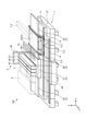
- FIG. 1 is a schematic perspective view of a droplet ejection device according to an embodiment.
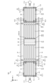
- FIG. 2 is a schematic plan view of the droplet ejection device according to the embodiment.
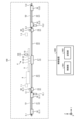
- FIG. 3 is a schematic side view of the droplet ejection device according to the embodiment.
- FIG. 4 is a schematic plan view of the first conveyance section according to the embodiment.
- FIG. 5 is a schematic plan view of a holding section included in the first conveyance section according to the embodiment.
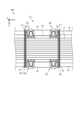
- FIG. 6 is a schematic side view of a holding section included in the first conveyance section according to the embodiment.
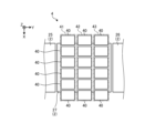
- FIG. 7 is a schematic plan view of the drawing unit according to the embodiment.
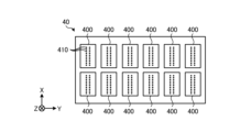
- FIG. 8 is a schematic bottom view of the carriage according to the embodiment.
- FIG. 9 is a schematic plan view of the maintenance section according to the embodiment.
- FIG. 10 is a schematic plan view of the periodic flushing section according to the embodiment.
- FIG. 11 is a schematic side view of the periodic flushing section according to the embodiment.
- FIG. 12 is a schematic plan view of the inspection section according to the embodiment.
- FIG. 13 is a schematic side view of the inspection section according to the embodiment.
- FIG. 14 is a flowchart showing the procedure of processing executed by the droplet ejection device according to the embodiment.
- FIG. 15 is a schematic diagram showing an example of the operation of the droplet ejection device according to the embodiment.
- FIG. 16 is a schematic diagram showing an example of the operation of the droplet ejection device according to the embodiment.
- FIG. 17 is a schematic diagram showing an example of the operation of the droplet ejection device according to the embodiment.
- FIG. 18 is a schematic diagram showing an example of the operation of the droplet ejection device according to the embodiment.
- FIG. 19 is a schematic diagram showing an example of the operation of the droplet ejection device according to the embodiment.
- FIG. 20 is a schematic diagram showing an example of the operation of the droplet ejection device according to the embodiment.
- FIG. 21 is a schematic diagram showing an example of the operation of the droplet ejection device according to the embodiment.
- FIG. 22 is a diagram showing an example of the arrangement of the first transfer device and the second transfer device in the first modification.
- FIG. 23 is a diagram showing another example of the arrangement of the first transfer device and the second transfer device in the first modification.
- FIG. 24 is a schematic perspective view of a droplet ejection device according to a second modification.
- each of the drawings referred to below shows an orthogonal coordinate system in which the X-axis direction, Y-axis direction, and Z-axis direction that are orthogonal to each other are defined, and the positive Z-axis direction is the vertically upward direction. There are cases. Further, the direction of rotation about the vertical axis is sometimes referred to as the ⁇ direction.
- FIG. 1 is a schematic perspective view of a droplet ejection device according to an embodiment.
- FIG. 2 is a schematic plan view of the droplet ejection device according to the embodiment.
- FIG. 3 is a schematic side view of the droplet ejection device according to the embodiment. Note that in FIGS. 1 to 3, a part of the configuration of the droplet ejection device may be omitted.
- the droplet discharge device 100 discharges droplets of functional liquid from above the substrate S while transporting the substrate S in the horizontal direction (here, the Y-axis direction).
- a predetermined pattern is drawn on the upper surface of the substrate S by discharging it using an inkjet method.
- the droplet ejection device 100 includes a base 1, a floating stage 2, a first conveyance section 3_1, a second conveyance section 3_2, a drawing section 4, a first pre-drawing flushing section 5_1, and a second A pre-drawing flushing section 5_2 is provided.
- the droplet ejection apparatus 100 also includes a first particle sensor 6_1, a second particle sensor 6_2, a first imaging section 7_1, a second imaging section 7_2, a maintenance section 8, a regular flushing section 9, and an inspection section. 10.
- the droplet ejection device 100 also includes a control device 1000.
- the droplet discharge device 100 includes two transport sections that hold and transport the substrate S (first transport section 3_1 and second transport section 3_2).
- the droplet ejection apparatus 100 can perform a series of processes on two substrates S (first substrate S1 and second substrate S2) in parallel using these two transport sections.
- the droplet ejection apparatus 100 may perform alignment processing on the second substrate S2 using the second transport section 3_2 while performing drawing processing on the first substrate S1 using the first transport section 3_1. I can do it. For this reason, the droplet ejection apparatus 100 according to the embodiment can improve productivity.
- the first substrate S1 and the second substrate S2 are, for example, glass substrates used in flat panel displays. Hereinafter, unless the first substrate S1 and the second substrate S2 are particularly distinguished, they will simply be referred to as a substrate S.
- the base 1 includes a first base 11, a second base 12, a pair of first guide rails 13, 13, and a pair of second guide rails 14, 14.
- the first base 11 and the second base 12 extend along the transport direction of the substrate S (here, the Y-axis direction).
- the upper surfaces of the first base 11 and the second base 12 are horizontal surfaces.
- the first base 11 is arranged on the upper surface of the second base 12.
- the first base 11 is narrower than the second base 12 in the direction perpendicular to the transport direction (X-axis direction).
- a pair of first guide rails 13, 13 are provided on the upper surface of the first base 11.
- a pair of first guide rails 13, 13 extend along the conveyance direction (Y-axis direction).
- the pair of first guide rails 13, 13 are arranged at intervals in a direction (X-axis direction) orthogonal to the transport direction.
- a pair of second guide rails 14, 14 are provided on the upper surface of the second base 12. Specifically, the pair of second guide rails 14, 14 are arranged on both sides of the first base 11 on the upper surface of the second base 12, that is, on the first base in the direction perpendicular to the conveyance direction (X-axis direction). It is provided on the side of 11.
- the pair of second guide rails 14, 14 extend along the conveyance direction (Y-axis direction).
- the pair of second guide rails 14, 14 are arranged at intervals in a direction (X-axis direction) orthogonal to the transport direction.
- the pair of second guide rails 14, 14 are shorter than the pair of first guide rails 13, 13.
- the first base 11 and the second base 12 are divided into a plurality of base members arranged in the transport direction (Y-axis direction), and cannot be partially removed or replaced with another base member of different length. is possible.
- the pair of first guide rails 13, 13 are also divided into a plurality of rail members lined up in the transport direction (Y-axis direction), and can be partially removed or replaced with another rail member of different length. It is possible to
- the floating stage 2 is arranged between a pair of first guide rails 13, 13.
- the levitation stage 2 ejects gas toward the substrate S from below the substrate S, and levitates the substrate S by the pressure of the ejected gas.
- the floating stage 2 includes a first loading/unloading stage 21, a second loading/unloading stage 22, a first processing stage 23, a second processing stage 24, a first transport stage 25, a second transport stage 26, and a third processing stage 27. These are the first loading/unloading stage 21, the first processing stage 23, the first transport stage 25, the third processing stage 27, the second transport stage 26, the second processing stage 24, and the second transport stage 24 along the Y-axis positive direction. They are arranged in the order of exit stage 22.
- the first loading/unloading stage 21 is arranged at one end of the floating stage 2 in the transport direction (Y-axis direction). At the first loading/unloading stage 21, the first substrate S1 is loaded and unloaded.
- the second loading/unloading stage 22 is arranged at the other end of the floating stage 2 in the transport direction (Y-axis direction). At the second loading/unloading stage 22, the second substrate S2 is loaded and unloaded.
- the first carry-in/out stage 21, the second carry-in/out stage 22, the first conveyance stage 25, and the second conveyance stage 26 have a plurality of ejection ports that eject compressed gas (for example, air) upward.
- compressed gas for example, air
- the first processing stage 23, the second processing stage 24, and the third processing stage 27 are equipped with a plurality of ejection ports that eject compressed gas upward, and a plurality of suction ports that suck the gas.
- the first processing stage 23, the second processing stage 24, and the third processing stage 27 eject compressed gas toward the lower surface of the substrate S, and at the same time, suck the air between the substrate S and the stages.
- the flying height can be adjusted with high precision.
- the first loading/unloading stage 21, the second loading/unloading stage 22, the first processing stage 23, the second processing stage 24, the first transport stage 25, and the second transport stage 26 are arranged in the transport direction (Y-axis direction) of the substrate S. It has a plurality of stage members extending along it. These multiple stage members are arranged at intervals in a direction (X-axis direction) orthogonal to the transport direction of the substrate S.
- the first transport unit 3_1 holds the first substrate S1 floated by the floating stage 2, and moves the held first substrate S1 along the floating stage 2.
- the second transport unit 3_2 holds the second substrate S2 floated by the floating stage 2, and moves the held second substrate S2 along the floating stage 2.
- the first transport unit 3_1 is capable of reciprocating between the first carry-in/out stage 21 and the second transport stage 26. Further, the second transport unit 3_2 is capable of reciprocating between the second carry-in/out stage 22 and the first transport stage 25.
- first transport section 3_1 and the second transport section 3_2 will be explained. Since the configurations of the first conveyance section 3_1 and the second conveyance section 3_2 are the same, the configuration of the first conveyance section 3_1 will be explained here, and the explanation of the configuration of the second conveyance section 3_2 will be omitted.
- FIG. 4 is a schematic plan view of the first transport section 3_1 according to the embodiment.
- the first conveyance section 3_1 includes a plurality of (here, two) moving sections 31 and a plurality of (here, four) holding sections 32.
- the moving part 31 is provided on the first guide rail 13 and moves along the first guide rail 13.
- the two moving parts 31 each have a driving part such as a motor, and can each move independently.
- the drive unit may be provided only on one of the two moving units 31.
- the four holding parts 32 are provided on the two moving parts 31, respectively, and hold the first substrate S1 from below. Specifically, two of the four holding parts 32 are provided on one of the two moving parts 31, and the remaining two of the four holding parts 32 are provided on the other of the two moving parts 31. provided.
- the four holding parts 32 attract and hold the four corners of the first substrate S1 from below the first substrate S1.
- the first substrate S1 is held at its four corners by suction by the four holding sections 32, and is transported by the two moving sections 31 while being floated by the floating stage 2.
- FIG. 5 is a schematic plan view of a holding section included in the first transport section 3_1 according to the embodiment.
- FIG. 6 is a schematic side view of a holding section included in the first transport section 3_1 according to the embodiment.
- the holding section 32 includes a base section 320, a first adjustment section 321, a second adjustment section 322, a rotating section 323, an arm section 324, and a first suction section 325. Equipped with.
- the first suction section 325 suction-holds the first substrate S1.
- the first suction section 325 includes a plurality of suction pads 326.
- the plurality of suction pads 326 are provided side by side in the horizontal direction (here, the Y-axis direction). Note that although an example in which the first suction section 325 includes three suction pads 326 is shown here, the number of suction pads 326 is not limited to three.
- the first suction unit 325 uses a plurality of suction pads 326 to suction the lower surface of the first substrate S1. As a result, the first substrate S1 is held by the first adsorption section 325.
- the base portion 320, the first adjustment portion 321, the second adjustment portion 322, the rotating portion 323, and the arm portion 324 are examples of adjustment portions that adjust the relative position of the first suction portion 325 with respect to the moving portion 31.
- the base part 320 is fixed on the moving part 31.
- the first adjustment section 321 is provided on the base section 320 and is movable on the base section 320 in a direction (X-axis direction) orthogonal to the conveyance direction.
- the second adjustment section 322 is provided on the first adjustment section 321 and is movable on the first adjustment section 321 along the conveyance direction (Y-axis direction).
- the rotating part 323 is provided on the second adjusting part 322 and is rotatable around the vertical axis (Z-axis).
- the arm portion 324 is a member extending in the horizontal direction, and is supported by the rotating portion 323 at its base end, and supports the first suction portion 325 at its distal end.
- the holding part 32 moves the first adsorption part 325 in the direction perpendicular to the transport direction (X-axis direction) by moving the first adjustment part 321 in the direction perpendicular to the transport direction (X-axis direction). ). That is, the first adjustment section 321 can adjust the position of the first suction section 325 with respect to the moving section 31 along the direction (X-axis direction) orthogonal to the conveyance direction.
- the holding section 32 can move the first suction section 325 in the transport direction (Y-axis direction) by moving the second adjustment section 322 along the transport direction (Y-axis direction). That is, the second adjustment section 322 can adjust the position of the first suction section 325 with respect to the moving section 31 along the conveyance direction (Y-axis direction).
- the adjustment section rotates the first suction section 325 supported by the rotation section 323 via the arm section 324 by rotating the rotation section 323 around the vertical axis (Z axis). ) can be rotated around the That is, the rotating part 323 can adjust the position of the first suction part 325 with respect to the moving part 31 along the circumferential direction centered on the vertical axis (Z-axis direction).
- the first adjustment section 321 and the second adjustment section 322 each have a drive section such as a motor, and can each move independently.
- the rotating section 323 is, for example, a bearing, does not have a driving section, and rotates the first suction section 325 so as to follow the movements of the first adjusting section 321 and the second adjusting section 322.
- the present invention is not limited to this, and the rotating portion 323 may be provided with a driving portion.
- the first transport section 3_1 and the second transport section 3_2 move along the same first guide rails 13, 13. In this way, by sharing the first guide rails 13, 13 with the first transport section 3_1 and the second transport section 3_2, increases in cost and footprint can be suppressed.
- the drawing unit 4 is arranged above the floating stage 2. Specifically, the drawing unit 4 is arranged above the third processing stage 27. The drawing unit 4 performs drawing on the upper surface of the substrate S by discharging a functional liquid toward the substrate S from above.
- FIG. 7 is a schematic plan view of the drawing unit 4 according to the embodiment.
- FIG. 8 is a schematic bottom view of the carriage according to the embodiment.
- the drawing section 4 includes a first carriage group 41, a second carriage group 42, and a third carriage group 43.
- the first carriage group 41, the second carriage group 42, and the third carriage group 43 are arranged along the conveyance direction (Y-axis direction).
- the first carriage group 41, the second carriage group 42, and the third carriage group 43 each include a plurality of (here, six) carriages 40.
- the plurality of carriages 40 are arranged in a direction (X-axis direction) perpendicular to the transport direction.
- the plurality of carriages 40 belonging to the first carriage group 41 are supported horizontally by a first beam section 45 provided in the drawing section 4 (see FIG. 1).
- the plurality of carriages 40 belonging to the second carriage group 42 are supported horizontally by a second beam section 46 included in the drawing section 4 .
- the plurality of carriages 40 belonging to the third carriage group 43 are supported horizontally by a third beam section 47 included in the drawing section 4 .
- the first beam portion 45, the second beam portion 46, and the third beam portion 47 are supported by a pair of pillars 48, 48.
- the pair of support columns 48, 48 are provided at both ends of the first beam portion 45, the second beam portion 46, and the third beam portion 47 in the direction (X-axis direction) orthogonal to the conveyance direction.
- the pair of support columns 48, 48 can move up and down the first beam section 45, the second beam section 46, and the third beam section 47. That is, the pair of pillars 48, 48 is an example of a lifting mechanism that raises and lowers the first beam part 45, the second beam part 46, and the third beam part 47.
- the pair of support columns 48, 48 have a first beam portion 45, a second beam portion 46, and a The third beam portion 47 is raised and lowered.
- the carriage 40 is, for example, a flat member.
- the carriage 40 is provided with a plurality of ejection heads 400.
- a total of 12 ejection heads 400 are provided in the carriage 40 in a matrix along the X-axis direction and the Y-axis direction. Note that although an example in which the carriage 40 is provided with 12 ejection heads 400 is shown here, the number of ejection heads 400 may be greater or less than 12.
- the ejection head 400 is located above the third processing stage 27 and ejects droplets of the functional liquid.
- the ejection head 400 is, for example, a piezo type nozzle head.
- a plurality of nozzles 410 are formed on the lower surface of the ejection head 400 (the surface facing the substrate S).
- the plurality of nozzles 410 are provided, for example, in a matrix along the X-axis direction and the Y-axis direction.
- the discharge head 400 has a pump section (not shown).
- the pump section includes a cavity that stores the functional fluid, a piezoelectric element, a diaphragm, etc. that changes the volume of the cavity, and the volume of the cavity is changed by applying voltage to the piezoelectric element and vibrating the diaphragm. droplets of the functional liquid are ejected from each nozzle 410.
- the discharge head 400 is provided with a functional liquid introduction part that is connected to the functional liquid tank via a supply tube, a head board that is connected to the control device 1000 (see FIG. 3) via a flexible flat cable, and the like. ing.
- the plurality of carriages 40 eject functional liquid from the plurality of ejection heads 400 onto the substrate S that is transported along the transport direction (Y-axis positive direction).
- the functional liquid is, for example, ink.
- the plurality of ejection heads 400 belonging to the first carriage group 41 eject red (R) ink. Furthermore, the plurality of ejection heads 400 belonging to the second carriage group 42 eject green (G) ink, and the plurality of ejection heads 400 belonging to the third carriage group 43 eject blue (B) ink.
- the pair of first pre-drawing flushing parts 5_1, 5_1 are arranged at both ends of the first transport part 3_1 in the transport direction (Y-axis direction). In other words, the pair of first pre-drawing flushing parts 5_1, 5_1 are arranged so as to sandwich the first transport part 3_1 in the transport direction (Y-axis direction).
- the pair of second pre-drawing flushing parts 5_2, 5_2 are arranged at both ends of the second transport part 3_2 in the transport direction (Y-axis direction). In other words, the pair of second pre-drawing flushing parts 5_2, 5_2 are arranged so as to sandwich the second transport part 3_2 in the transport direction (Y-axis direction).
- each first pre-drawing flushing section 5_1 includes a liquid receiving section 51 that receives the functional liquid discharged from the discharging head 400, and a pair that moves the liquid receiving section 51 in the transport direction (Y-axis direction).
- the moving parts 52, 52 are provided.
- the liquid receiver 51 is a long plate-shaped member extending in a direction (X-axis direction) perpendicular to the conveying direction.
- the liquid receiving portion 51 is formed of a porous material such as porous resin, for example.
- the pair of moving parts 52, 52 are provided on the pair of first guide rails 13, 13, respectively, and horizontally support the liquid receiving part 51 from below.
- the pair of moving parts 52, 52 each have a driving part such as a motor, and are movable along the pair of first guide rails 13, 13. That is, the pair of moving parts 52, 52 can move the liquid receiving part 51 integrally with the first transport part 3_1.
- the drive unit may be provided only on one of the two moving units 52.
- the pair of moving parts 52 may be configured to be driven by a driving part included in the pair of moving parts 31. In this case, neither of the pair of moving parts 52 may have a driving part.
- the structure of the second pre-drawing flushing section 5_2 is also similar to the structure of the first pre-drawing flushing section 5_1 shown in FIG. 4.
- the first particle sensor 6_1 detects particles attached to the upper surface of the first substrate S1.
- the first particle sensor 6_1 includes a first unit 61 and a second unit 62.
- the first unit 61 is provided at one end of the first processing stage 23 in a direction (X-axis direction) perpendicular to the transport direction.
- the second unit 62 is provided at the other end of the first processing stage 23 in the direction (X-axis direction) perpendicular to the transport direction. That is, the first unit 61 and the second unit 62 are arranged to face each other with the first processing stage 23 in between in the direction (X-axis direction) perpendicular to the transport direction.
- the first particle sensor 6_1 is arranged between the first loading/unloading stage 21 and the ejection head 400 in the transport direction (Y-axis direction). That is, the first particle sensor 6_1 is arranged at a position further in the positive direction of the Y-axis than the first loading/unloading stage 21 and further in the negative direction of the Y-axis than the ejection head 400.
- the first unit 61 has a light projecting section
- the second unit 62 has a light receiving section.
- the light projecting section of the first unit 61 emits laser light horizontally toward the light receiving section of the second unit 62.
- the light receiving section of the second unit 62 receives the laser beam irradiated from the light projecting section of the first unit 61.
- the first particle sensor 6_1 outputs the amount of received laser light to a control device 1000, which will be described later.
- the control device 1000 detects particles attached to the upper surface of the first substrate S1 based on the detection result obtained from the first particle sensor 6_1.
- the second particle sensor 6_2 detects particles attached to the upper surface of the second substrate S2.
- the second particle sensor 6_2 includes a first unit 61 and a second unit 62.
- the first unit 61 is provided at one end of the second processing stage 24 in a direction (X-axis direction) perpendicular to the transport direction.
- the second unit 62 is provided at the other end of the second processing stage 24 in the direction (X-axis direction) perpendicular to the transport direction. That is, the first unit 61 and the second unit 62 are arranged to face each other with the second processing stage 24 in between in the direction (X-axis direction) orthogonal to the transport direction.
- the second particle sensor 6_2 is arranged between the second loading/unloading stage 22 and the ejection head 400 in the transport direction (Y-axis direction). That is, the second particle sensor 6_2 is arranged at a position further in the negative Y-axis direction than the second carry-in/out stage 22 and further in the positive Y-axis direction than the ejection head 400.
- the second particle sensor 6_2 outputs the amount of the received laser light to the control device 1000, which will be described later.
- the control device 1000 detects particles attached to the upper surface of the second substrate S2 based on the detection result obtained from the second particle sensor 6_2.
- first unit 61 may include a light receiving section in addition to the light projecting section.
- second unit 62 may also include a light projecting section in addition to the light receiving section.
- the first imaging unit 7_1 is arranged above the first transport stage 25, for example. Note that the first imaging unit 7_1 may be arranged above the first processing stage 23. The first imaging unit 7_1 may be disposed at least between the first loading/unloading stage 21 and the ejection head 400. The first imaging unit 7_1 images the upper surface of the first substrate S1 after the functional liquid has been discharged (after drawing). Specifically, the first imaging unit 7_1 images the upper surface of the first substrate S1 that is moving from the third processing stage 27 toward the first loading/unloading stage 21. The image captured by the first imaging unit 7_1 is output to the control device 1000. The control device 1000 determines whether the drawing state of the first substrate S1 is good or bad based on the image captured by the first imaging unit 7_1.
- the second imaging unit 7_2 is arranged above the second transport stage 26, for example. Note that the second imaging unit 7_2 may be arranged above the second processing stage 24. The second imaging unit 7_2 may be disposed at least between the second loading/unloading stage 22 and the ejection head 400.
- the second imaging unit 7_2 images the upper surface of the second substrate S2 after the functional liquid has been discharged (after drawing). Specifically, the second imaging unit 7_2 images the upper surface of the second substrate S2 that is moving from the third processing stage 27 toward the second loading/unloading stage 22.
- the image captured by the second imaging unit 7_2 is output to the control device 1000.
- the control device 1000 determines whether the drawing state of the second substrate S2 is good or bad based on the image captured by the second imaging unit 7_2.
- the maintenance section 8, periodic flushing section 9, and inspection section 10 are arranged above the floating stage 2.
- Each of the maintenance section 8, periodic flushing section 9, and inspection section 10 is horizontally supported at both ends in a direction (X-axis direction) perpendicular to the conveyance direction by a pair of support columns (not shown).
- This support column is provided on a pair of second guide rails 14, 14, and is movable along the pair of second guide rails 14, 14 by a drive section (not shown). That is, the maintenance section 8, periodic flushing section 9, and inspection section 10 are capable of reciprocating movement along the conveyance direction.
- the maintenance section 8 and the periodic flushing section 9 wait at a first standby position above the floating stage 2 and between the first loading/unloading stage 21 and the third processing stage 27.
- the inspection unit 10 waits at a second standby position above the floating stage 2 and between the second loading/unloading stage 22 and the third processing stage 27 .
- the second standby position may be above the second transport stage 26. That is, the inspection unit 10 may be on standby above the second transport stage 26. By setting this position as the second standby position, it is possible to shorten the time required for the inspection process described later.
- the maintenance section 8 moves on second guide rails 14, 14 extending along the conveyance direction (Y-axis direction).
- the maintenance section 8 is arranged at a first standby position between the first loading/unloading stage 21 and the third processing stage 27 when not performing maintenance work.
- the maintenance section 8 moves from the first standby position to a maintenance position between the third processing stage 27 and the drawing section 4.
- the maintenance section 8 performs suction processing and wiping processing at the maintenance position.
- the suction process is a process for forcibly discharging the functional liquid from the ejection head 400 by suctioning the functional liquid remaining in the ejection head 400 from the nozzle 410.
- the wiping process is a process of wiping the nozzle surface (lower surface) of the ejection head 400 after the suction process.
- the maintenance section 8 performs suction processing and wiping processing at preset timing. For example, the maintenance section 8 performs suction processing and wiping processing several times a day.
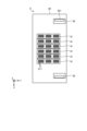
- FIG. 9 is a schematic plan view of the maintenance section 8 according to the embodiment.
- the maintenance section 8 includes a plurality of suction sections 81 and a plurality of wiping sections 82.
- the plurality of suction units 81 are provided, for example, in accordance with the number of carriages 40 in the direction (X-axis direction) orthogonal to the transport direction. That is, the plurality of suction parts 81 are provided corresponding to the plurality of carriages 40.
- the plurality of suction units 81 may be provided in three rows in the transport direction depending on the number of carriages 40 in the transport direction (Y-axis direction).
- Each suction unit 81 is movable in the transport direction and in the vertical direction.
- Each suction unit 81 suctions the functional liquid from the plurality of ejection heads 400 .
- Each suction section 81 includes a plurality of caps 811.
- Each cap 811 is provided corresponding to the number of ejection heads 400, and is provided so as to be able to face the ejection heads 400 in the vertical direction.
- Each cap 811 can be brought into close contact with the corresponding ejection head 400 by moving the suction section 81 in the vertical direction. Each cap 811 comes into close contact with the corresponding ejection head 400 during suction processing, and receives the functional liquid sucked from the corresponding ejection head 400. In the suction process, the functional liquid remaining in the ejection head 400 is suctioned by creating a negative pressure in the cap 811 that is in close contact with the ejection head 400 by a suction mechanism.
- Each suction unit 81 moves along the conveyance direction (Y-axis direction) with respect to the support stand 80 of the maintenance unit 8. Specifically, each suction unit 81 moves between a retreat position and a suction position along the conveyance direction.
- the retracted position is a position where each suction section 81 corresponding to the carriage 40 where the wiping process is performed by each wiping section 82 retracts.
- the retracted position is also the reference position of each suction section 81.
- the suction position is a position where each cap 811 is below the corresponding ejection head 400 when performing suction processing and wiping processing.
- the wiping unit 82 performs a wiping process on each ejection head 400 into which the functional liquid has been sucked through the suction process. That is, the wiping section 82 wipes the plurality of ejection heads 400 into which the functional liquid has been sucked by the plurality of suction sections 81 .
- the wiping parts 82 are provided at both ends of the support base 80 in the direction (X-axis direction) perpendicular to the transport direction. That is, two wiping parts 82 are provided, one wiping part 82 is provided at one end of the support base 80 in the direction perpendicular to the transport direction (X-axis direction), and the other wiping part 82 is provided in the direction perpendicular to the transport direction (X-axis direction). It is provided at the other end of the support base 80 in the orthogonal direction (X-axis direction).
- Each wiping section 82 is movable along the direction (X-axis direction) orthogonal to the conveyance direction. Each wiping section 82 wipes away the functional liquid adhering to the tip of the ejection head 400 by moving the wiping sheet 821 while rotating it using a roll section.
- the periodic flushing section 9 is used for periodic flushing processing in which the functional liquid is ejected from the ejection head 400 during a period when the functional liquid is not ejected to the first substrate S1 and the second substrate S2. Periodic flushing processing is executed at preset timing. For example, periodic flushing processing is performed several times a day. The periodic flushing section 9 receives the functional liquid ejected from the ejection head 400 in the periodic flushing process.
- the inspection unit 10 uses a film to receive the functional liquid ejected from the ejection head 400 in an inspection process executed at a timing different from the periodic flushing process described above, and images the functional liquid with an imaging unit.
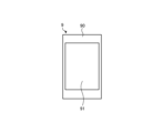
- FIG. 10 is a schematic plan view of the periodic flushing section 9 according to the embodiment.
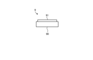
- FIG. 11 is a schematic side view of the periodic flushing section 9 according to the embodiment.
- the periodic flushing section 9 includes a base section 90 and a liquid receiving section 91 arranged on the base section 90.
- the base portion 90 is supported horizontally by the pair of pillars described above, and is movable along the pair of second guide rails 14, 14.
- the liquid receiving portion 91 is made of, for example, porous resin, and receives the functional liquid discharged from the plurality of discharge heads 400 .
- a drain pipe (not shown) is connected to the liquid receiver 91, and the functional fluid received by the liquid receiver 91 is discharged via the drain pipe.
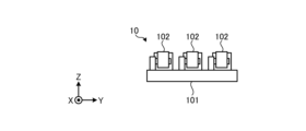
- FIG. 12 is a schematic plan view of the inspection section 10 according to the embodiment.
- FIG. 13 is a schematic side view of the inspection section 10 according to the embodiment.
- the inspection section 10 includes a base section 101, a plurality of (here, three) films 102, and a plurality of third imaging sections 103 (see FIGS. 2 and 3).
- the base portion 101 is supported horizontally by the pair of pillars described above, and is movable along the pair of second guide rails 14, 14.
- a plurality of (here, three) films 102 are arranged side by side on the base portion 101 along the conveyance direction (Y-axis direction).
- the plurality of films 102 correspond to the first carriage group 41, the second carriage group 42, and the third carriage group 43, respectively.
- the plurality of films 102 may be made of different materials.
- the plurality of films 102 may be selected from materials suitable for the type of functional fluid to be received (for example, whether or not they are hydrophilic, surface roughness, etc.).
- the third imaging unit 103 images the functional liquid discharged onto the film 102. As shown in FIGS. 2 and 3, the third imaging section 103 is arranged near the drawing section 4 between the drawing section 4 and the base section 101.
- the control device 1000 controls the inspection section 10 to place the base section 101 below the drawing section 4. Subsequently, the control device 1000 controls the drawing unit 4 to discharge the functional liquid onto the plurality of films 102. Subsequently, the control device 1000 positions the base section 101 of the inspection section 10 below the third imaging section 103. The control device 1000 then controls the third imaging unit 103 to image the film 102 from above. The imaging result by the third imaging unit 103 is output to the control device 1000, and the control device 1000 determines whether the functional fluid is being discharged normally.
- the inspection process by the inspection unit 10 is performed, for example, every time the drawing unit 4 finishes the drawing process on the substrate S.
- the present invention is not limited to this, and the inspection process may be performed, for example, after the drawing process on the first substrate S1 is finished and the subsequent drawing process on the second substrate S2 is finished. Further, the inspection process may be performed, for example, after the drawing process on a plurality of (three or more) substrates S is completed.
- the droplet ejection device 100 includes a plurality of first pre-alignment mechanisms 15_1 and a plurality of second pre-alignment mechanisms 15_2.
- the plurality of first pre-alignment mechanisms 15_1 are arranged on the first loading/unloading stage 21. Specifically, the plurality of first pre-alignment mechanisms 15_1 are arranged at the four corners of the first substrate S1 when the first substrate S1 is located on the first loading/unloading stage 21. In the example shown in FIG. 2, two first pre-alignment mechanisms 15_1 are arranged on one side of the first substrate S1. These two first pre-alignment mechanisms 15_1 are arranged around a corner on one side of the first substrate S1.
- Each first pre-alignment mechanism 15_1 is movable along the horizontal direction (X-axis direction or Y-axis direction). Specifically, the four first pre-alignment mechanisms 15_1 adjacent to the first substrate S1 in the transport direction (Y-axis direction) are horizontally movable along the transport direction. Furthermore, the four first pre-alignment mechanisms 15_1 adjacent to the first substrate S1 in the direction (X-axis direction) perpendicular to the transport direction are horizontally movable along the direction perpendicular to the transport direction. Further, each first pre-alignment mechanism 15_1 is movable up and down.
- the plurality of second pre-alignment mechanisms 15_2 are arranged on the second loading/unloading stage 22. Specifically, the plurality of second pre-alignment mechanisms 15_2 are arranged at the four corners of the second substrate S2 when the second substrate S2 is located on the second loading/unloading stage 22. In the example shown in FIG. 2, two second pre-alignment mechanisms 15_2 are arranged on one side of the second substrate S2. These two second pre-alignment mechanisms 15_2 are arranged around a corner on one side of the second substrate S2.
- Each second pre-alignment mechanism 15_2 is movable along the horizontal direction (X-axis direction or Y-axis direction). Specifically, the four second pre-alignment mechanisms 15_2 adjacent to the second substrate S2 in the transport direction (Y-axis direction) are horizontally movable along the transport direction. Further, the four first pre-alignment mechanisms 15_1 adjacent to the second substrate S2 in the direction (X-axis direction) perpendicular to the transport direction are horizontally movable along the direction perpendicular to the transport direction. Further, each second pre-alignment mechanism 15_2 is movable up and down.
- the plurality of first pre-alignment mechanisms 15_1 are used for pre-alignment processing.
- the pre-alignment process involves adjusting the position of the first substrate S1 after it is transferred from the first transfer device 17_1 (described later) to the first transport unit 3_1 and before the first substrate S1 is held by the first transport unit 3_1. This is a process of adjusting. Specifically, in the pre-alignment process, the plurality of first pre-alignment mechanisms 15_1 move in the horizontal direction (X-axis direction or Y direction) so as to approach the first substrate S1. The position of the first substrate S1 can be adjusted to some extent.
- the plurality of second pre-alignment mechanisms 15_2 are used for pre-alignment processing on the second substrate S2.
- the droplet discharge device 100 includes a plurality of first alignment cameras 16_1 and a plurality of second alignment cameras 16_2.
- a plurality of (here, two) first alignment cameras 16_1 are arranged below the first loading/unloading stage 21. Specifically, each first alignment camera 16_1 is arranged between two stage members included in the first loading/unloading stage 21 in plan view, and images the first substrate S1 from between these two stage members. .
- a plurality of (here, two) second alignment cameras 16_2 are arranged below the second loading/unloading stage 22. Specifically, each second alignment camera 16_2 is arranged between two stage members of the second loading/unloading stage 22 in plan view, and images the second substrate S2 from between these two stage members. .
- the plurality of first alignment cameras 16_1 are used for the main alignment process.
- This alignment process is a process for accurately adjusting the position of the first substrate S1 held by the first transport unit 3_1 after the pre-alignment process.
- the plurality of first alignment cameras 16_1 capture images of alignment marks provided on the first substrate S1.
- the control device 1000 drives the first adjustment section 321 and the second adjustment section 322 of each holding section 32 based on the images captured by the plurality of first alignment cameras 16_1. 1 Adjust the position of the substrate S1.
- the plurality of second alignment cameras 16_2 are used for the main alignment process for the second substrate S2.
- the droplet ejection device 100 includes a first transfer device 17_1 and a second transfer device 17_2.
- the first transfer device 17_1 and the second transfer device 17_2 are, for example, horizontal articulated robots.
- the first transfer device 17_1 carries the first substrate S1 into and out of the first carry-in/out stage 21.
- the second transfer device 17_2 carries the second substrate S2 into and out of the second carry-in/out stage 22.
- the first transfer device 17_1 is arranged at a position adjacent to the first loading/unloading stage 21 (first transfer position of the first loading/unloading stage 21) in the transport direction (Y-axis direction). Ru.
- the second transfer device 17_2 is arranged at a position adjacent to the second carry-in/out stage 22 (first transfer position of the second carry-in/out stage 22) in the transport direction (Y-axis direction). Note that the installation locations of the first transfer device 17_1 and the second transfer device 17_2 are not limited to the example shown in FIG. 2. This point will be discussed later.
- the droplet ejection device 100 includes a control device 1000.
- the control device 1000 is, for example, a computer, and includes a control section 1001 and a storage section 1002.
- the storage unit 1002 stores a program (an example of a droplet ejection program) that controls various processes executed in the droplet ejection apparatus 100.
- the control unit 1001 controls the operation of the droplet ejection apparatus 100 by reading and executing a program stored in the storage unit 1002.
- Such a program may be one that has been recorded on a computer-readable storage medium, and may be one that is installed from the storage medium into the storage unit 1002 of the control device 1000.
- a computer-readable storage medium is a medium that non-temporarily records the program and data used by the program. Examples of such storage media include hard disks (HD), flexible disks (FD), compact disks (CD), magnet optical disks (MO), and memory cards.
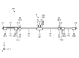
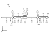
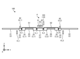
- FIG. 14 is a flowchart showing the procedure of processing executed by the droplet ejection apparatus 100 according to the embodiment. Further, FIGS. 15 to 21 are schematic diagrams showing operation examples of the droplet ejection apparatus 100 according to the embodiment. Note that each processing procedure shown in FIG. 14 is executed under the control of the control device 1000.
- a first import process is performed (step S101).
- the first loading process is a process in which the first substrate S1 is transferred from the first transfer device 17_1 to the first transport unit 3_1 on the first loading/unloading stage 21.
- the first transport section 3_1 is placed on the first carry-in/out stage 21.
- the first substrate S1 is transferred from the first transfer device 17_1 to the first transport unit 3_1.
- the first loading/unloading stage 21 is provided with lifting pins (not shown), and the first transfer device 17_1 places the first substrate S1 on the lifting pins. Thereafter, the elevating pin descends, and the second substrate S2 is transferred from the elevating pin to the holding section 32 of the first transport section 3_1.
- first pre-alignment processing is performed (step S102).
- the control device 1000 adjusts the position of the first substrate S1 by driving the plurality of first pre-alignment mechanisms 15_1.
- a first holding process is performed (step S103).
- the control device 1000 controls the first transport section 3_1 to cause the first suction section 325 of each holding section 32 to suction and hold the first substrate S1.
- the first main alignment process is a process of adjusting the attitude of the first substrate S1 in the horizontal plane by controlling the adjustment unit of the first transport unit 3_1 based on the image of the alignment mark captured by the first alignment camera 16_1.
- the control device 1000 images the alignment mark provided on the first substrate S1 using the plurality of first alignment cameras 16_1. After that, the control device 1000 controls the first adjustment section 321 and the second adjustment section 322 of the plurality of holding sections 32 included in the first transport section 3_1 to adjust the position of the first substrate S1.
- a first particle detection process is performed (step S105).
- the control device 1000 controls the moving unit 31 of the first transport unit 3_1 to move the first substrate S1 from the first loading/unloading stage 21 to the first transport stage 25, that is, along the Y axis. Move in the forward direction.
- the control device 1000 causes the first particle sensor 6_1 to irradiate the first substrate S1 passing through the first processing stage 23 with a laser beam.
- the control device 1000 detects particles attached to the upper surface of the first substrate S1 based on the amount of laser light received by the light receiving section (see FIG. 16).
- the first drawing process is a process in which droplets of the functional liquid are ejected from the ejection head 400 onto the first substrate S1 while moving the first transport unit 3_1 holding the first substrate S1 to pass below the ejection head 400. It is.
- the control device 1000 reciprocates the first transport section 3_1 twice between the first transport stage 25 and the second transport stage 26, and removes droplets of the functional liquid from the drawing section 4 on each of the forward and return passes. (Figs. 17 to 20).
- the first transport stage 25 is an example of a first position between the first transport stage 21 and the ejection head 400.
- the second transport stage 26 is an example of a second position between the ejection head 400 and the second carry-in/out stage 22.
- a second loading process, a second pre-alignment process, a second holding process, a second main alignment process, and a second process are performed on the second substrate S2.
- Particle detection processing is performed (steps S107 to S111).
- the second carry-in process (step S107) and the second pre-alignment process (step S108) are similar to the first carry-in process and the first pre-alignment process described above.
- the second holding process (step S109), the second main alignment process (step S110), and the second particle detection process (step S111) are the same as the first holding process, first main alignment process, and first particle detection process described above. This is the process.
- the second loading process, the second pre-alignment process, the second holding process, and the second main alignment process for the second substrate S2 are performed during the first reciprocating movement and the second outward movement with respect to the first substrate S1. (See Figures 17 to 19). Then, the subsequent second particle detection process for the second substrate S2 is performed during the second return trip to the first substrate S1. That is, the control device 1000 moves the second transport unit 3_2 in the second particle detection process (and the second drawing process) in synchronization with the movement of the first transport unit 3_1 to the first transport stage 25 in the first drawing process. The movement to the second transport stage 26 is started (see FIG. 20).
- control device 1000 performs the second pre-alignment process and the second main alignment process in parallel with the first drawing process.
- control device 1000 may perform the inspection process by the inspection unit 10 after the first drawing process and before the second drawing process.
- control device 1000 may perform the second export process after the first export process.
- a first drawing determination process is performed (step S112).
- the control device 1000 controls the first transport section 3_1 to move the first substrate S1 from the first transport stage 25 to the first loading/unloading stage 21, and controls the first imaging section 7_1. Then, the upper surface of the first substrate S1 that is being moved is imaged. The control device 1000 determines whether the drawing state of the first substrate S1 is good or bad based on the image captured by the first imaging unit 7_1.
- a first export process is performed (step S113).
- the first transport unit 3_1 is returned to the first loading/unloading stage 21 to release the holding of the first substrate S1 by the holding unit 32, and in the first unloading process, the control device 1000 3_1 releases the suction and holding of the first substrate S1.
- the control device 1000 controls the first transfer device 17_1 to receive the first substrate S1 from the first transport unit 3_1 via a lift pin (not shown).
- a second drawing process is performed on the second substrate S2 in parallel with the first drawing determination process and the first unloading process on the first substrate S1 (step S114).
- the second drawing process on the second substrate S2 is performed by moving the second conveyance unit 3_2 holding the second substrate S2 and passing the functional liquid from the ejection head 400 onto the second substrate S2. This is a process of ejecting droplets.
- the second drawing process is similar to the first drawing process for the first substrate S1 described above (see FIG. 21).
- control device 1000 reciprocates the second transport section 3_2 twice between the second transport stage 26 (an example of the second position) and the first transport stage 25 (an example of the first position), while Droplets of the functional liquid are ejected from the drawing unit 4 on each return trip.
- a second drawing determination process (step S115) and a second unloading process (step S116) are performed on the second substrate S2, and a series of processes on the first substrate S1 and the second substrate S2 are completed.
- the second drawing determination process and the second carry-out process for the second substrate S2 are the same as the first drawing judgment process and the first carry-out process for the first substrate S1.
- the droplet ejection apparatus 100 includes the two transport sections (the first transport section 3_1 and the second transport section 3_2), so that the second substrate can be processed in parallel with the processing on the first substrate S1. Processing for S2 can be performed. Specifically, the droplet ejection apparatus 100 performs a loading process (second loading process) and an alignment process (second printing process) for the second substrate S2 in parallel with the writing process (first writing process) for the first substrate S1. alignment and second main alignment processing). Thereby, the droplet ejection apparatus 100 according to the embodiment can shorten the total processing time when continuously processing a plurality of substrates S. Therefore, according to the droplet ejection apparatus 100 according to the embodiment, productivity can be improved.
- the arrangement of the first transfer device 17_1 and the second transfer device 17_2 is not limited to the example shown in FIG. 2.
- FIG. 22 is a diagram showing an example of the arrangement of the first transfer device 17_1 and the second transfer device 17_2 in the first modification.
- FIG. 23 is a diagram showing another example of the arrangement of the first transfer device 17_1 and the second transfer device 17_2 in the first modification.
- a position adjacent to each of the first loading/unloading stage 21 and the second loading/unloading stage 22 in the transport direction (Y-axis direction) is defined as a first transfer position P1. Also, one of the two positions adjacent to each other in the direction (X-axis direction) orthogonal to the transport direction when viewed from each of the first loading/unloading stage 21 and the second loading/unloading stage 22 is set as the second transfer position P2, and the other is set as the second loading/unloading position P2. It is set as the third transfer position P3.
- a transfer position located on the negative side of the X-axis with respect to the first carry-in/out stage 21 and the second carry-in/out stage 22 is referred to as a second transfer position P2, and the first carry-in/out stage 21 and the second carry-in/out stage 22 are A transfer position located on the positive side of the X-axis with respect to the stage 22 is defined as a third transfer position P3.
- the second transfer device 17_2 it may be arranged at the third transfer position P3 with respect to the second loading/unloading stage 22.
- the droplet ejecting device 100 is configured such that the second transfer device 17_2 may be arranged at a third transfer position P3 with respect to the second loading/unloading stage 22.
- the first transfer device 17_1 is arranged at any one of the first transfer position P1, the second transfer position P2, and the third transfer position P3 with respect to the first loading/unloading stage 21.
- the transfer position may be different from the transfer position where the transfer position is.
- the present invention is not limited to this.
- the second transfer device 17_2 when the first transfer device 17_1 is placed at the second transfer position P2 with respect to the first carry-in/out stage 21, the second transfer device 17_2 is also placed in the second transfer position P2 with respect to the second carry-in/out stage 22. It may be placed at the second transfer position P2.
- the first transfer device 17_1 when the first transfer device 17_1 is placed at the third transfer position P3 with respect to the first carry-in/out stage 21, the second transfer device 17_2 is also placed in the third transfer position P3 with respect to the second carry-in/out stage 22. may be placed in
- FIG. 24 is a schematic perspective view of a droplet ejection device 100 according to a second modification.
- a droplet ejection apparatus 100 according to the second modification is obtained by removing the configuration used for processing the first substrate S1 from the droplet ejection apparatus 100 shown in FIG. 1.
- the droplet ejection device 100 according to the second modification example includes the first loading/unloading stage 21, the first processing stage 23, the first transport section 3_1, and the first drawing from the droplet ejection device 100 shown in FIG. The front flushing part 5_1 has been removed.
- the droplet ejection apparatus 100 according to the second modification includes the droplet ejection apparatus 100 shown in FIG. 17_1 has been removed.
- the first base 11 is divided into a plurality of base members, and the base member located below the first loading/unloading stage 21 is also removed from the droplet ejecting device 100.
- the pair of first guide rails 13, 13 are divided into a plurality of rail members, and the rail members located on the sides of the first loading/unloading stage 21 are also removed from the droplet ejecting device 100.
- the present invention is not limited to this, and the second loading/unloading stage 22 and the second transport section 3_2 may be detachably attached to the droplet discharge device 100. In this way, even if at least one of the first loading/unloading stage 21 and the first transporting section 3, and the second loading/unloading stage 22 and the second transporting section 3 are detachable from the droplet ejecting device 100, good.
- the droplet ejection apparatus 100 is configured to include one loading/unloading station (here, the second loading/unloading stage 22) where the substrate S (here, the second substrate S2) is loaded and unloaded. Good too.
- the droplet ejection device includes a floating stage (the floating stage 2 as an example) and a transport section (as an example the first transport section 3_1 or The second transport unit 3_2), a discharge head (for example, the discharge head 400), and a control unit (for example, the control unit 1001).
- the floating stage extends along the transport direction of the substrate (for example, the first substrate S1 or the second substrate S2), and levitates the substrate by the pressure of the ejected gas.
- the transport section holds the substrate floated by the floating stage and moves it along the floating stage.
- the ejection head is located above the floating stage and ejects droplets of the functional liquid.
- the control section controls the transport section and the ejection head.
- the floating stage has a loading/unloading stage (for example, the first loading/unloading stage 21 or the second loading/unloading stage 22) through which substrates are loaded and unloaded.
- the control unit performs a loading process in which the substrate is transferred to the transport unit on the loading/unloading stage, and then moves the transport unit that holds the substrate to pass below the discharge head while applying droplets of functional liquid from the discharge head to the substrate.
- a drawing process of ejecting the liquid and then a carrying-out process of returning the carrying unit to the loading/unloading stage and releasing the holding of the substrate by the carrying unit are executed.
- the droplet ejection device includes a floating stage (the floating stage 2 as an example), a first transport section (the first transport section 3_1 as an example), It includes a second conveyance section (for example, the second conveyance section 3_2) and an ejection head (for example, the ejection head 400).
- the floating stage extends along the conveyance direction of the first substrate (for example, the first substrate S1) and the second substrate (for example, the second substrate S2). 2. Float the board.
- the first transport section holds the first substrate floated by the floating stage and moves it along the floating stage.
- the second transport section holds the second substrate floated by the floating stage and moves it along the floating stage.
- the ejection head is located above the floating stage and ejects droplets of the functional liquid.
- the floating stage includes a first loading/unloading stage located at one end in the transport direction, where the first substrate is loaded and unloaded, and a second loading/unloading stage located at the other end in the transporting direction, where the second substrate is loaded and unloaded. Equipped with a loading/unloading stage.
- productivity can be improved.
- the present disclosure can also have the following configuration.
- a levitation stage that extends along the conveyance direction of the substrate and levitates the substrate by the pressure of ejected gas; a transport unit that holds the substrate floated by the floating stage and moves it along the floating stage; an ejection head located above the floating stage and ejecting droplets of functional liquid; a control unit that controls the transport unit and the ejection head;
- the floating stage has a loading/unloading stage on which the substrate is loaded and unloaded,
- the control unit includes: a carry-in process of passing the substrate to the transport unit on the carry-in/out stage; after that, a drawing process in which droplets of the functional liquid are ejected from the ejection head onto the substrate while moving the transport unit holding the substrate to pass below the ejection head; Thereafter, the droplet ejecting apparatus performs an unloading process of returning the transporting section to the loading/unloading stage and releasing the holding of the substrate by the transporting section.
- the levitation stage is a first loading/unloading stage that is located at one end in the transport direction, and where the first substrate is loaded and unloaded; a second loading/unloading stage located at the other end in the transporting direction, on which loading and unloading of the second substrate is performed.
- a first imaging unit that is disposed between the first loading/unloading stage and the discharge head and photographs the first substrate onto which the functional liquid has been discharged; Any one of (2) to (4), further comprising: a second imaging unit that is disposed between the second loading/unloading stage and the discharge head and photographs the second substrate onto which the functional liquid has been discharged.
- the droplet ejection device described in . (6) a first particle sensor that is disposed between the first loading/unloading stage and the ejection head and detects particles attached to the upper surface of the first substrate; any one of (2) to (5), further comprising: a second particle sensor that is disposed between the second loading/unloading stage and the ejection head and detects particles attached to the upper surface of the second substrate.
- the droplet ejection device described in . (7) a maintenance section that performs a suction process to suck the functional liquid from the nozzle of the ejection head and a wiping process to wipe the nozzle surface of the ejection head; Periodic flushing that receives the functional liquid discharged from the discharge head in a periodic flushing process in which the functional liquid is discharged from the discharge head during a period when the functional liquid is not discharged to the first substrate and the second substrate.
- the inspection unit is configured to handle the liquid according to any one of (2) to (6), which is on standby at a second standby position above the floating stage and between the second loading/unloading stage and the ejection head.
- Droplet ejection device Droplet ejection device.
- a first pre-drawing flushing section that is disposed at both ends of the first conveyance section in the conveyance direction, is movable integrally with the first conveyance section, and receives the functional liquid discharged from the discharge head;
- a second pre-drawing flushing section that is disposed at both ends of the second transport section in the transport direction, is movable integrally with the second transport section, and receives the functional liquid discharged from the discharge head;
- the droplet ejection device according to any one of (2) to (7), comprising: (9) a first transfer device for loading and unloading the first substrate with respect to the first loading/unloading stage; a second transfer device for loading and unloading the second substrate with respect to the second loading/unloading stage;
- a first transfer position is a position adjacent to the transport direction when viewed from each of the first carry-in/out stage and the second carry-in/out stage, and a position adjacent to the transport direction when viewed from each of the first carry-in/out stage and the second carry-in/
- the droplet ejection device according to any one of items 8) to 8). (10) comprising a control unit that controls the first transport unit, the second transport unit, and the ejection head;
- the control unit includes: a first carrying-in process of passing the first substrate to the first transport unit on the first carrying-in/out stage; a second carrying-in process of passing the second substrate to the second transport section on the second carrying-in/out stage; After the first loading process, droplets of the functional liquid are ejected from the ejection head onto the first substrate while moving the first transport unit holding the first substrate and passing it below the ejection head.
- a first drawing process to After the first drawing process, a first carrying-out process of returning the first carrying unit to the first loading/unloading stage to release the first substrate from being held by the first carrying unit; After the first unloading process or in parallel with the first unloading process, the second conveyance unit holding the second substrate is moved to pass below the ejection head, and is attached to the second substrate.
- a second drawing process of ejecting droplets of the functional liquid from the ejection head; After the second drawing process, a second carry-out process is performed in which the second transport unit is returned to the second carry-in/out stage and the holding of the second substrate by the second carry unit is released; (2) to ( 9) The droplet ejection device according to any one of 9).
- the first drawing process includes drawing the first image between a first position between the first carry-in/out stage and the ejection head and a second position between the ejection head and the second carry-in/out stage. ejecting droplets of the functional liquid from the ejection head to the first substrate while reciprocating the transport unit;
- the second drawing process includes discharging droplets of the functional liquid from the discharging head onto the second substrate while reciprocating the second transport unit between the second position and the first position.
- the second transport unit includes an adjustment unit that adjusts the attitude of the held second substrate in a horizontal plane, In parallel with the first drawing process, the control unit controls the adjustment unit based on the image of the alignment mark captured by the alignment camera to adjust the attitude of the second substrate in a horizontal plane.
- the droplet ejection device according to (10) or (11), which performs alignment processing.
- Discharge device is any one of (10) to (12)
- a levitation stage located at one end in the transport direction of a levitation stage that extends along the transport direction of the first and second substrates and levitates the first and second substrates by the pressure of ejected gas;
- a first transfer unit that holds the first substrate levitated by the floating stage and transfers the first substrate to a first transport unit that moves it along the floating stage.
- the loading process and A second loading/unloading stage which is located at the other end of the floating stage in the conveying direction and carrying in and out of the second substrate, holds the second substrate floated by the floating stage and transfers it to the floating stage.
- a second drawing step of ejecting droplets of the functional liquid from the ejection head and a second carrying-out step of returning the second transport section to the second carry-in/out stage to release the second substrate from being held by the second transport section after the second drawing step.
- a second loading/unloading stage which is located at the other end of the floating stage in the conveying direction and carrying in and out of the second substrate, holds the second substrate floated by the floating stage and transfers it to the floating stage.
- a first drawing step of ejecting droplets of the functional liquid from the ejection head to one substrate After the first drawing procedure, a first carrying-out procedure of returning the first carrying unit to the first loading/unloading stage to release the holding of the first substrate by the first carrying unit; After the first unloading procedure or in parallel with the first unloading procedure, the second conveyance section holding the second substrate is moved to pass below the ejection head, and the second substrate is moved toward the second substrate.
- a second drawing step of ejecting droplets of the functional liquid from the ejection head After the second drawing step, a second carrying-out procedure of returning the second carrying section to the second loading/unloading stage and releasing the holding of the second substrate by the second carrying section is implemented.
- a temporary computer-readable storage medium After the second drawing procedure, a second carrying-out procedure of returning the second carrying section to the second loading/unloading stage and releasing the holding of the second substrate by the second carrying section is implemented.
Landscapes
- Coating Apparatus (AREA)
- Application Of Or Painting With Fluid Materials (AREA)
Abstract
本開示による液滴吐出装置は、浮上ステージと、搬送部と、吐出ヘッドと、制御部とを備える。浮上ステージは、基板の搬送方向に沿って延在し、噴出する気体の圧力によって基板を浮上させる。搬送部は、浮上ステージによって浮上した基板を保持して浮上ステージに沿って移動させる。吐出ヘッドは、浮上ステージの上方に位置し、機能液の液滴を吐出する。制御部は、搬送部および吐出ヘッドを制御する。浮上ステージは、基板の搬入および搬出が行われる搬入出ステージを有する。制御部は、搬入出ステージにおいて基板を搬送部に渡す搬入処理と、その後、基板を保持した搬送部を移動させて吐出ヘッドの下方を通過させつつ基板に対し吐出ヘッドから機能液の液滴を吐出する描画処理と、その後、搬送部を搬入出ステージに戻して搬送部による基板の保持を解除する搬出処理とを実行する。
Description
本開示は、液滴吐出装置、液滴吐出方法および記憶媒体に関する。
従来、浮上ステージによって浮上させた基板を水平方向に搬送しつつ、基板の上方から機能液の液滴をインクジェット方式で吐出することにより、基板に対して描画を行う液滴吐出装置が知られている。
本開示は、生産性を向上させることができる技術を提供する。
本開示の一態様による液滴吐出装置は、浮上ステージと、搬送部と、吐出ヘッドと、制御部とを備える。浮上ステージは、基板の搬送方向に沿って延在し、噴出する気体の圧力によって基板を浮上させる。搬送部は、浮上ステージによって浮上した基板を保持して浮上ステージに沿って移動させる。吐出ヘッドは、浮上ステージの上方に位置し、機能液の液滴を吐出する。制御部は、搬送部および吐出ヘッドを制御する。浮上ステージは、基板の搬入および搬出が行われる搬入出ステージを有する。制御部は、搬入出ステージにおいて基板を搬送部に渡す搬入処理と、その後、基板を保持した搬送部を移動させて吐出ヘッドの下方を通過させつつ基板に対し吐出ヘッドから機能液の液滴を吐出する描画処理と、その後、搬送部を搬入出ステージに戻して搬送部による基板の保持を解除する搬出処理とを実行する。
本開示によれば、生産性を向上させることができる。
以下に、本開示による液滴吐出装置、液滴吐出方法および記憶媒体を実施するための形態(以下、「実施形態」と記載する)について図面を参照しつつ詳細に説明する。なお、この実施形態により本開示が限定されるものではない。また、各実施形態は、処理内容を矛盾させない範囲で適宜組み合わせることが可能である。また、以下の各実施形態において同一の部位には同一の符号を付し、重複する説明は省略される。
また、以下に示す実施形態では、「一定」、「直交」、「垂直」あるいは「平行」といった表現が用いられる場合があるが、これらの表現は、厳密に「一定」、「直交」、「垂直」あるいは「平行」であることを要しない。すなわち、上記した各表現は、たとえば製造精度、設置精度などのずれを許容するものとする。
また、以下参照する各図面では、説明を分かりやすくするために、互いに直交するX軸方向、Y軸方向およびZ軸方向を規定し、Z軸正方向を鉛直上向き方向とする直交座標系を示す場合がある。また、鉛直軸を回転中心とする回転方向をθ方向と呼ぶ場合がある。
(液滴吐出装置の構成)
まず、図1~図3を参照して、実施形態に係る液滴吐出装置の構成について説明する。図1は、実施形態に係る液滴吐出装置の模式的な斜視図である。図2は、実施形態に係る液滴吐出装置の模式的な平面図である。図3は、実施形態に係る液滴吐出装置の模式的な側面図である。なお、図1~図3では、液滴吐出装置が備える構成の一部を省略して示している場合がある。
まず、図1~図3を参照して、実施形態に係る液滴吐出装置の構成について説明する。図1は、実施形態に係る液滴吐出装置の模式的な斜視図である。図2は、実施形態に係る液滴吐出装置の模式的な平面図である。図3は、実施形態に係る液滴吐出装置の模式的な側面図である。なお、図1~図3では、液滴吐出装置が備える構成の一部を省略して示している場合がある。
図1~図3に示すように、実施形態に係る液滴吐出装置100は、基板Sを水平方向(ここでは、Y軸方向)に搬送しつつ、基板Sの上方から機能液の液滴をインクジェット方式で吐出することにより基板Sの上面に所定パターンの描画を行う。
実施形態に係る液滴吐出装置100は、ベース1と、浮上ステージ2と、第1搬送部3_1と、第2搬送部3_2と、描画部4と、第1描画前フラッシング部5_1と、第2描画前フラッシング部5_2とを備える。また、液滴吐出装置100は、第1パーティクルセンサ6_1と、第2パーティクルセンサ6_2と、第1撮像部7_1と、第2撮像部7_2と、メンテナンス部8と、定期フラッシング部9と、検査部10とを備える。また、液滴吐出装置100は、制御装置1000を備える。
液滴吐出装置100は、基板Sを保持して搬送する搬送部を2つ備えている(第1搬送部3_1および第2搬送部3_2)。かかる液滴吐出装置100は、これら2つの搬送部を用いて2枚の基板S(第1基板S1および第2基板S2)に対する一連の処理を並行して行うことができる。たとえば、液滴吐出装置100は、第1搬送部3_1を用いて第1基板S1に対する描画処理を行っている最中に、第2搬送部3_2を用いて第2基板S2のアライメント処理を行うことができる。このようなことから、実施形態に係る液滴吐出装置100によれば、生産性を高めることができる。
第1基板S1および第2基板S2は、たとえば、フラットパネルディスプレイに用いられるガラス基板である。以下では、第1基板S1および第2基板S2を特に区別しない場合、これらを単に基板Sと呼称する。
(ベース)
ベース1は、第1ベース11と、第2ベース12と、一対の第1ガイドレール13,13と、一対の第2ガイドレール14,14とを備える。
ベース1は、第1ベース11と、第2ベース12と、一対の第1ガイドレール13,13と、一対の第2ガイドレール14,14とを備える。
第1ベース11および第2ベース12は、基板Sの搬送方向(ここでは、Y軸方向)に沿って延在する。第1ベース11および第2ベース12の上面は水平面である。第1ベース11は、第2ベース12の上面に配置されている。第1ベース11は、第2ベース12と比較して、搬送方向と直交する方向(X軸方向)に幅狭である。
一対の第1ガイドレール13,13は、第1ベース11の上面に設けられる。一対の第1ガイドレール13,13は、搬送方向(Y軸方向)に沿って延在している。一対の第1ガイドレール13,13は、搬送方向と直交する方向(X軸方向)に間隔をあけて配置される。
一対の第2ガイドレール14,14は、第2ベース12の上面に設けられる。具体的には、一対の第2ガイドレール14,14は、第2ベース12の上面のうち、第1ベース11の両側方、すなわち、搬送方向と直交する方向(X軸方向)における第1ベース11の側方に設けられる。一対の第2ガイドレール14,14は、搬送方向(Y軸方向)に沿って延在している。一対の第2ガイドレール14,14は、搬送方向と直交する方向(X軸方向)に間隔をあけて配置される。一対の第2ガイドレール14,14は、一対の第1ガイドレール13,13よりも短い。
第1ベース11および第2ベース12は、搬送方向(Y軸方向)に並ぶ複数のベース部材に分割されており、部分的に取り外したり、長さの異なる別のベース部材に交換したりすることが可能である。同様に、一対の第1ガイドレール13,13も、搬送方向(Y軸方向)に並ぶ複数のレール部材に分割されており、部分的に取り外したり、長さの異なる別のレール部材に交換したりすることが可能である。
(浮上ステージ)
浮上ステージ2は、一対の第1ガイドレール13,13の間に配置される。浮上ステージ2は、基板Sの下方から基板Sに向けて気体を噴出し、噴出する気体の圧力によって基板Sを浮上させる。かかる浮上ステージ2は、第1搬入出ステージ21と、第2搬入出ステージ22と、第1処理ステージ23と、第2処理ステージ24と、第1搬送ステージ25と、第2搬送ステージ26と、第3処理ステージ27とを備える。これらは、Y軸正方向に沿って第1搬入出ステージ21、第1処理ステージ23、第1搬送ステージ25、第3処理ステージ27、第2搬送ステージ26、第2処理ステージ24および第2搬入出ステージ22の順に配置される。
浮上ステージ2は、一対の第1ガイドレール13,13の間に配置される。浮上ステージ2は、基板Sの下方から基板Sに向けて気体を噴出し、噴出する気体の圧力によって基板Sを浮上させる。かかる浮上ステージ2は、第1搬入出ステージ21と、第2搬入出ステージ22と、第1処理ステージ23と、第2処理ステージ24と、第1搬送ステージ25と、第2搬送ステージ26と、第3処理ステージ27とを備える。これらは、Y軸正方向に沿って第1搬入出ステージ21、第1処理ステージ23、第1搬送ステージ25、第3処理ステージ27、第2搬送ステージ26、第2処理ステージ24および第2搬入出ステージ22の順に配置される。
第1搬入出ステージ21は、浮上ステージ2の搬送方向(Y軸方向)における一端に配置される。第1搬入出ステージ21では、第1基板S1の搬入および搬出が行われる。第2搬入出ステージ22は、浮上ステージ2の搬送方向(Y軸方向)における他端に配置される。第2搬入出ステージ22では、第2基板S2の搬入および搬出が行われる。
第1搬入出ステージ21、第2搬入出ステージ22、第1搬送ステージ25および第2搬送ステージ26は、上方に向けて圧縮された気体(たとえば、空気)を噴出する複数の噴出口を有する。
第1処理ステージ23、第2処理ステージ24、第3処理ステージ27は、上方に向けて圧縮された気体を噴出する複数の噴出口に加え、気体を吸引する複数の吸引口を備えている。第1処理ステージ23、第2処理ステージ24および第3処理ステージ27は、圧縮された気体を基板Sの下面に向けて噴出するとともに、基板Sおよびステージ間の空気を吸引することにより、基板Sの浮上高を高精度に調整することができる。
第1搬入出ステージ21、第2搬入出ステージ22、第1処理ステージ23、第2処理ステージ24、第1搬送ステージ25および第2搬送ステージ26は、基板Sの搬送方向(Y軸方向)に沿って延在する複数のステージ部材を有している。これら複数のステージ部材は、基板Sの搬送方向と直交する方向(X軸方向)に互いに間隔をあけて並べられている。
(第1搬送部および第2搬送部)
第1搬送部3_1は、浮上ステージ2によって浮上した第1基板S1を保持し、保持した第1基板S1を浮上ステージ2に沿って移動させる。第2搬送部3_2は、浮上ステージ2によって浮上した第2基板S2を保持し、保持した第2基板S2を浮上ステージ2に沿って移動させる。第1搬送部3_1は、第1搬入出ステージ21および第2搬送ステージ26間を往復移動可能である。また、第2搬送部3_2は、第2搬入出ステージ22および第1搬送ステージ25間を往復移動可能である。
第1搬送部3_1は、浮上ステージ2によって浮上した第1基板S1を保持し、保持した第1基板S1を浮上ステージ2に沿って移動させる。第2搬送部3_2は、浮上ステージ2によって浮上した第2基板S2を保持し、保持した第2基板S2を浮上ステージ2に沿って移動させる。第1搬送部3_1は、第1搬入出ステージ21および第2搬送ステージ26間を往復移動可能である。また、第2搬送部3_2は、第2搬入出ステージ22および第1搬送ステージ25間を往復移動可能である。
ここで、第1搬送部3_1および第2搬送部3_2の構成について説明する。第1搬送部3_1および第2搬送部3_2の構成は同様であるため、ここでは第1搬送部3_1の構成について説明することとし、第2搬送部3_2の構成の説明については省略する。
図4は、実施形態に係る第1搬送部3_1の模式的な平面図である。図4に示すように、第1搬送部3_1は、複数(ここでは、2つ)の移動部31と、複数(ここでは、4つ)の保持部32とを備える。
移動部31は、第1ガイドレール13上に設けられ、第1ガイドレール13に沿って移動する。2つの移動部31は、それぞれモータ等の駆動部を有しており、各々独立して移動することが可能である。なお、駆動部は、2つの移動部31のうち一方にのみ設けられてもよい。
4つの保持部32は、2つの移動部31上にそれぞれ設けられ、第1基板S1の下方から第1基板S1を保持する。具体的には、4つの保持部32のうち2つは、2つの移動部31のうち一方に設けられ、4つの保持部32のうち残りの2つは、2つの移動部31のうち他方に設けられる。4つの保持部32は、第1基板S1の四隅を第1基板S1の下方から吸着保持する。第1基板S1は、4つの保持部32によって四隅を吸着保持され、且つ、浮上ステージ2によって浮上した状態で、2つの移動部31によって搬送される。
ここで、保持部32の構成について図5および図6を参照して説明する。図5は、実施形態に係る第1搬送部3_1が有する保持部の模式的な平面図である。図6は、実施形態に係る第1搬送部3_1が有する保持部の模式的な側面図である。
図5および図6に示すように、保持部32は、ベース部320と、第1調整部321と、第2調整部322と、回動部323と、アーム部324と、第1吸着部325とを備える。
第1吸着部325は、第1基板S1を吸着保持する。具体的には、第1吸着部325は、複数の吸着パッド326を備える。複数の吸着パッド326は、水平方向(ここでは、Y軸方向)に並んで設けられる。なお、ここでは、第1吸着部325が3つの吸着パッド326を備える場合の例を示しているが、吸着パッド326の数は、3つに限定されない。第1吸着部325は、複数の吸着パッド326によって、第1基板S1の下面を吸着する。これにより、第1基板S1は、第1吸着部325に保持される。
ベース部320、第1調整部321、第2調整部322、回動部323およびアーム部324は、移動部31に対する第1吸着部325の相対位置を調整する調整部の一例である。
ベース部320は、移動部31上に固定される。第1調整部321は、ベース部320上に設けられ、ベース部320上を搬送方向と直交する方向(X軸方向)に沿って移動可能である。第2調整部322は、第1調整部321上に設けられ、第1調整部321上を搬送方向(Y軸方向)に沿って移動可能である。回動部323は、第2調整部322上に設けられ、鉛直軸(Z軸)周りに回転可能である。アーム部324は、水平方向に延在する部材であり、基端部において回動部323に支持され、先端部において第1吸着部325を支持する。
このように、保持部32は、第1調整部321を搬送方向と直交する方向(X軸方向)に沿って移動させることにより、第1吸着部325を搬送方向と直交する方向(X軸方向)に移動させることができる。すなわち、第1調整部321は、移動部31に対する第1吸着部325の位置を搬送方向と直交する方向(X軸方向)に沿って調整することができる。
また、保持部32は、第2調整部322を搬送方向(Y軸方向)に沿って移動させることにより、第1吸着部325を搬送方向(Y軸方向)に移動させることができる。すなわち、第2調整部322は、移動部31に対する第1吸着部325の位置を搬送方向(Y軸方向)に沿って調整することができる。
また、調整部は、回動部323が鉛直軸(Z軸)まわりに回動することにより、回動部323にアーム部324を介して支持された第1吸着部325を鉛直軸(Z軸)まわりに回動させることができる。すなわち、回動部323は、移動部31に対する第1吸着部325の位置を鉛直軸(Z軸方向)を中心とする周方向に沿って調整することができる。
第1調整部321および第2調整部322は、それぞれモータ等の駆動部を有しており、各々独立して移動することが可能である。一方、回動部323は、たとえば軸受であって、駆動部を有しておらず、第1調整部321および第2調整部322の動きに追従するように第1吸着部325を回動させる。なお、これに限らず、回動部323に駆動部が設けられてもよい。
第1搬送部3_1および第2搬送部3_2は、同一の第1ガイドレール13,13に沿って移動する。このように、第1搬送部3_1と第2搬送部3_2とで第1ガイドレール13,13を共用することで、コストの増大やフットプリントの増大を抑えることができる。
(描画部)
描画部4は、浮上ステージ2の上方に配置される。具体的には、描画部4は、第3処理ステージ27の上方に配置される。描画部4は、基板Sの上方から基板Sに向けて機能液を吐出することにより、基板Sの上面に描画を行う。
描画部4は、浮上ステージ2の上方に配置される。具体的には、描画部4は、第3処理ステージ27の上方に配置される。描画部4は、基板Sの上方から基板Sに向けて機能液を吐出することにより、基板Sの上面に描画を行う。
ここで、描画部4の構成について図7および図8を参照して説明する。図7は、実施形態に係る描画部4の模式的な平面図である。図8は、実施形態に係るキャリッジの模式的な底面図である。
図7に示すように、描画部4は、第1キャリッジ群41と、第2キャリッジ群42と、第3キャリッジ群43とを備える。第1キャリッジ群41、第2キャリッジ群42および第3キャリッジ群43は、搬送方向(Y軸方向)に沿って並べられる。
第1キャリッジ群41、第2キャリッジ群42および第3キャリッジ群43は、それぞれ複数(ここでは、6つ)のキャリッジ40を含む。第1キャリッジ群41、第2キャリッジ群42および第3キャリッジ群43の各々において、複数のキャリッジ40は、搬送方向と直交する方向(X軸方向)に並べられている。
第1キャリッジ群41に属する複数のキャリッジ40は、描画部4が備える第1梁部45によって水平に支持される(図1参照)。第2キャリッジ群42に属する複数のキャリッジ40は、描画部4が備える第2梁部46によって水平に支持される。第3キャリッジ群43に属する複数のキャリッジ40は、描画部4が備える第3梁部47によって水平に支持される。
第1梁部45、第2梁部46および第3梁部47は、一対の支柱48,48によって支持される。一対の支柱48,48は、搬送方向と直交する方向(X軸方向)における第1梁部45、第2梁部46および第3梁部47の両端部に設けられる。一対の支柱48,48は、第1梁部45、第2梁部46および第3梁部47を昇降可能である。すなわち、一対の支柱48,48は、第1梁部45、第2梁部46および第3梁部47を昇降させる昇降機構の一例である。具体的には、一対の支柱48,48は、基板Sに対する機能液の吐出が行われる処理位置と、処理位置より上方の退避位置との間で第1梁部45、第2梁部46および第3梁部47を昇降させる。
図8に示すように、キャリッジ40は、たとえば平板状の部材である。キャリッジ40には、複数の吐出ヘッド400が設けられている。一例として、図8に示す例において、キャリッジ40には、合計12個の吐出ヘッド400がX軸方向およびY軸方向に沿ってマトリクス状に設けられている。なお、ここでは、キャリッジ40に12個の吐出ヘッド400が設けられる場合の例を示したが、吐出ヘッド400の個数は、12個より多くてもよいし少なくてもよい。
吐出ヘッド400は、第3処理ステージ27の上方に位置し、機能液の液滴を吐出する。吐出ヘッド400は、たとえばピエゾ方式のノズルヘッドである。吐出ヘッド400の下面(基板Sとの対向面)には、複数のノズル410が形成される。複数のノズル410は、例えばX軸方向およびY軸方向に沿ってマトリクス状に設けられている。
吐出ヘッド400は、図示しないポンプ部を有する。ポンプ部は、機能液を貯めるキャビティ、キャビティの体積を変化させる圧電素子や振動板等を含んで構成され、圧電素子に電圧を印加して振動板を振動させることにより、キャビティの体積を変化させて各ノズル410から機能液の液滴を吐出させる。その他、吐出ヘッド400には、供給チューブを介して機能液タンクに接続される機能液導入部や、フレキシブルフラットケーブルを介して制御装置1000(図3参照)に接続されるヘッド基板等が設けられている。
複数のキャリッジ40は、搬送方向(Y軸正方向)に沿って搬送される基板Sに対して複数の吐出ヘッド400から機能液を吐出する。機能液は、たとえばインクである。
実施形態において、第1キャリッジ群41に属する複数の吐出ヘッド400は、赤(R)のインクを吐出する。また、第2キャリッジ群42に属する複数の吐出ヘッド400は、緑(G)のインクを吐出し、第3キャリッジ群43に属する複数の吐出ヘッド400は、青(B)のインクを吐出する。
(第1描画前フラッシング部および第2描画前フラッシング部)
一対の第1描画前フラッシング部5_1,5_1は、搬送方向(Y軸方向)における第1搬送部3_1の両端部に配置される。言い換えれば、一対の第1描画前フラッシング部5_1,5_1は、搬送方向(Y軸方向)において第1搬送部3_1を挟むように配置される。
一対の第1描画前フラッシング部5_1,5_1は、搬送方向(Y軸方向)における第1搬送部3_1の両端部に配置される。言い換えれば、一対の第1描画前フラッシング部5_1,5_1は、搬送方向(Y軸方向)において第1搬送部3_1を挟むように配置される。
一対の第2描画前フラッシング部5_2,5_2は、搬送方向(Y軸方向)における第2搬送部3_2の両端部に配置される。言い換えれば、一対の第2描画前フラッシング部5_2,5_2は、搬送方向(Y軸方向)において第2搬送部3_2を挟むように配置される。
図4に示すように、各第1描画前フラッシング部5_1は、吐出ヘッド400から吐出された機能液を受ける液受部51と、液受部51を搬送方向(Y軸方向)に移動させる一対の移動部52,52とを備える。液受部51は、搬送方向と直交する方向(X軸方向)に延在する長尺板状の部材である。液受部51は、たとえば多孔質樹脂等の多孔質体で形成される。
一対の移動部52,52は、一対の第1ガイドレール13,13上にそれぞれ設けられており、液受部51を下方から水平に支持する。一対の移動部52,52は、それぞれモータ等の駆動部を有しており、一対の第1ガイドレール13,13に沿って移動可能である。すなわち、一対の移動部52,52は、液受部51を第1搬送部3_1と一体的に移動させることができる。なお、駆動部は、2つの移動部52のうち一方にのみ設けられてもよい。また、一対の移動部52は、一対の移動部31が有する駆動部によって従動的に移動する構成であってもよい。この場合、一対の移動部52は、いずれも駆動部を有していなくてもよい。
ここでは、第1描画前フラッシング部5_1の構成について説明したが、第2描画前フラッシング部5_2の構成も図4に示す第1描画前フラッシング部5_1の構成と同様である。
(第1パーティクルセンサおよび第2パーティクルセンサ)
第1パーティクルセンサ6_1は、第1基板S1の上面に付着したパーティクルを検出する。具体的には、第1パーティクルセンサ6_1は、第1ユニット61と第2ユニット62とを備える。第1ユニット61は、搬送方向と直交する方向(X軸方向)における第1処理ステージ23の一端に設けられる。第2ユニット62は、搬送方向と直交する方向(X軸方向)における第1処理ステージ23の他端に設けられる。すなわち、第1ユニット61および第2ユニット62は、搬送方向と直交する方向(X軸方向)において第1処理ステージ23を挟むように対向配置される。このように、第1パーティクルセンサ6_1は、搬送方向(Y軸方向)において、第1搬入出ステージ21と吐出ヘッド400との間に配置される。すなわち、第1パーティクルセンサ6_1は、第1搬入出ステージ21よりもY軸正方向かつ吐出ヘッド400よりもY軸負方向の位置に配置される。
第1パーティクルセンサ6_1は、第1基板S1の上面に付着したパーティクルを検出する。具体的には、第1パーティクルセンサ6_1は、第1ユニット61と第2ユニット62とを備える。第1ユニット61は、搬送方向と直交する方向(X軸方向)における第1処理ステージ23の一端に設けられる。第2ユニット62は、搬送方向と直交する方向(X軸方向)における第1処理ステージ23の他端に設けられる。すなわち、第1ユニット61および第2ユニット62は、搬送方向と直交する方向(X軸方向)において第1処理ステージ23を挟むように対向配置される。このように、第1パーティクルセンサ6_1は、搬送方向(Y軸方向)において、第1搬入出ステージ21と吐出ヘッド400との間に配置される。すなわち、第1パーティクルセンサ6_1は、第1搬入出ステージ21よりもY軸正方向かつ吐出ヘッド400よりもY軸負方向の位置に配置される。
第1ユニット61は投光部を有し、第2ユニット62は受光部を有する。第1ユニット61の投光部は、第2ユニット62の受光部に向けて水平にレーザ光を照射する。第2ユニット62の受光部は、第1ユニット61の投光部から照射されたレーザ光を受光する。第1パーティクルセンサ6_1は、受光したレーザ光の光量を後述する制御装置1000へ出力する。制御装置1000は、第1パーティクルセンサ6_1から取得した検出結果に基づいて第1基板S1の上面に付着したパーティクルを検出する。
第2パーティクルセンサ6_2は、第2基板S2の上面に付着したパーティクルを検出する。具体的には、第2パーティクルセンサ6_2は、第1ユニット61と、第2ユニット62とを備える。第1ユニット61は、搬送方向と直交する方向(X軸方向)における第2処理ステージ24の一端に設けられる。第2ユニット62は、搬送方向と直交する方向(X軸方向)における第2処理ステージ24の他端に設けられる。すなわち、第1ユニット61および第2ユニット62は、搬送方向と直交する方向(X軸方向)において第2処理ステージ24を挟むように対向配置される。このように、第2パーティクルセンサ6_2は、搬送方向(Y軸方向)において、第2搬入出ステージ22と吐出ヘッド400との間に配置される。すなわち、第2パーティクルセンサ6_2は、第2搬入出ステージ22よりもY軸負方向かつ吐出ヘッド400よりもY軸正方向の位置に配置される。
第2パーティクルセンサ6_2は、受光したレーザ光の光量を後述する制御装置1000へ出力する。制御装置1000は、第2パーティクルセンサ6_2から取得した検出結果に基づいて第2基板S2の上面に付着したパーティクルを検出する。
なお、第1ユニット61は、投光部に加えて受光部を備えていてもよい。また、第2ユニット62も、受光部に加えて投光部を備えていてもよい。
(第1撮像部および第2撮像部)
第1撮像部7_1は、たとえば第1搬送ステージ25の上方に配置される。なお、第1撮像部7_1は、第1処理ステージ23の上方に配置されてもよい。第1撮像部7_1は、少なくとも、第1搬入出ステージ21と吐出ヘッド400との間に配置されていればよい。第1撮像部7_1は、機能液が吐出された後(描画後)の第1基板S1の上面を撮像する。具体的には、第1撮像部7_1は、第3処理ステージ27から第1搬入出ステージ21に向かって移動中の第1基板S1の上面を撮像する。第1撮像部7_1によって撮像された画像は、制御装置1000に出力される。制御装置1000は、第1撮像部7_1によって撮像された画像に基づいて、第1基板S1の描画状態の良否を判定する。
第1撮像部7_1は、たとえば第1搬送ステージ25の上方に配置される。なお、第1撮像部7_1は、第1処理ステージ23の上方に配置されてもよい。第1撮像部7_1は、少なくとも、第1搬入出ステージ21と吐出ヘッド400との間に配置されていればよい。第1撮像部7_1は、機能液が吐出された後(描画後)の第1基板S1の上面を撮像する。具体的には、第1撮像部7_1は、第3処理ステージ27から第1搬入出ステージ21に向かって移動中の第1基板S1の上面を撮像する。第1撮像部7_1によって撮像された画像は、制御装置1000に出力される。制御装置1000は、第1撮像部7_1によって撮像された画像に基づいて、第1基板S1の描画状態の良否を判定する。
第2撮像部7_2は、たとえば第2搬送ステージ26の上方に配置される。なお、第2撮像部7_2は、第2処理ステージ24の上方に配置されてもよい。第2撮像部7_2は、少なくとも、第2搬入出ステージ22と吐出ヘッド400との間に配置されていればよい。第2撮像部7_2は、機能液が吐出された後(描画後)の第2基板S2の上面を撮像する。具体的には、第2撮像部7_2は、第3処理ステージ27から第2搬入出ステージ22に向かって移動中の第2基板S2の上面を撮像する。第2撮像部7_2によって撮像された画像は、制御装置1000に出力される。制御装置1000は、第2撮像部7_2によって撮像された画像に基づいて、第2基板S2の描画状態の良否を判定する。
(メンテナンス部、定期フラッシング部および検査部)
メンテナンス部8、定期フラッシング部9および検査部10は、浮上ステージ2の上方に配置される。メンテナンス部8、定期フラッシング部9および検査部10の各々は、搬送方向と直交する方向(X軸方向)における両端部を図示しない一対の支柱によって水平に支持されている。この支柱は、一対の第2ガイドレール14,14上に設けられており、図示しない駆動部によって一対の第2ガイドレール14,14に沿って移動可能である。すなわち、メンテナンス部8、定期フラッシング部9および検査部10は、搬送方向に沿って往復移動可能である。
メンテナンス部8、定期フラッシング部9および検査部10は、浮上ステージ2の上方に配置される。メンテナンス部8、定期フラッシング部9および検査部10の各々は、搬送方向と直交する方向(X軸方向)における両端部を図示しない一対の支柱によって水平に支持されている。この支柱は、一対の第2ガイドレール14,14上に設けられており、図示しない駆動部によって一対の第2ガイドレール14,14に沿って移動可能である。すなわち、メンテナンス部8、定期フラッシング部9および検査部10は、搬送方向に沿って往復移動可能である。
図1に示すように、メンテナンス部8および定期フラッシング部9は、浮上ステージ2の上方かつ第1搬入出ステージ21と第3処理ステージ27との間の第1待機位置にて待機する。一方、検査部10は、浮上ステージ2の上方かつ第2搬入出ステージ22と第3処理ステージ27との間の第2待機位置にて待機する。たとえば、第2待機位置は、第2搬送ステージ26の上方であってもよい。すなわち、検査部10は、第2搬送ステージ26の上方にて待機していてもよい。かかる位置を第2待機位置とすることで、後述する検査処理に要する時間を短縮することができる。
なお、上記の「第1搬入出ステージ21(第2搬入出ステージ22)と第3処理ステージ27との間」は、「第1搬入出ステージ21(第2搬入出ステージ22)と吐出ヘッド400との間」と言い換えてもよい。
メンテナンス部8は、搬送方向(Y軸方向)に沿って延在する第2ガイドレール14,14上を移動する。メンテナンス部8は、メンテナンス作業を行わない場合には、第1搬入出ステージ21と第3処理ステージ27との間の第1待機位置に配置されている。一方、メンテナンス部8は、メンテナンス作業を行う場合には、第1待機位置から第3処理ステージ27と描画部4との間のメンテナンス位置に移動する。
メンテナンス部8は、メンテナンス位置において、吸引処理およびワイピング処理を行う。吸引処理は、吐出ヘッド400内に残存する機能液をノズル410から吸引することにより、吐出ヘッド400から機能液を強制的に排出する処理である。ワインピング処理は、吸引処理後、吐出ヘッド400のノズル面(下面)を払拭する処理である。
メンテナンス部8は、予め設定されたタイミングで、吸引処理およびワイピング処理を行う。たとえば、メンテナンス部8は、1日に数回、吸引処理およびワイピング処理を行う。
かかるメンテナンス部8の構成例について図9を参照して説明する。図9は、実施形態に係るメンテナンス部8の模式的な平面図である。図9に示すように、メンテナンス部8は、複数の吸引部81と、複数のワイピング部82とを備える。
複数の吸引部81は、たとえば搬送方向と直交する方向(X軸方向)におけるキャリッジ40の数に応じて設けられる。すなわち、複数の吸引部81は、複数のキャリッジ40に対応して設けられる。複数の吸引部81は、搬送方向(Y軸方向)におけるキャリッジ40の数に応じて搬送方向に3列設けられてもよい。各吸引部81は、搬送方向および上下方向にそれぞれ移動可能である。各吸引部81は、複数の吐出ヘッド400から機能液を吸引する。
各吸引部81は、複数のキャップ811を備える。各キャップ811は、吐出ヘッド400の数に対応して設けられ、上下方向において吐出ヘッド400に対向可能となるように設けられる。
各キャップ811は、吸引部81が上下方向に移動することによって、対応する吐出ヘッド400に密着可能である。各キャップ811は、吸引処理時に、対応する吐出ヘッド400に密着し、対応する吐出ヘッド400から吸引される機能液を受ける。吸引処理では、吐出ヘッド400に密着したキャップ811内が吸引機構によって負圧にされることによって、吐出ヘッド400内に残った機能液が吸引される。
各吸引部81は、メンテナンス部8の支持台80に対し、搬送方向(Y軸方向)に沿ってそれぞれ移動する。具体的には、各吸引部81は、退避位置と吸引位置との間を搬送方向に沿ってそれぞれ移動する。退避位置は、各ワイピング部82によってワイピング処理が行われるキャリッジ40に対応する各吸引部81が退避する位置である。退避位置は、各吸引部81の基準位置でもある。吸引位置は、吸引処理およびワイピング処理を行う場合に、各キャップ811が、対応する吐出ヘッド400の下方となる位置である。
ワイピング部82は、吸引処理によって機能液が吸引された各吐出ヘッド400に対しワイピング処理を行う。すなわち、ワイピング部82は、複数の吸引部81によって機能液が吸引された複数の吐出ヘッド400を払拭する。
ワイピング部82は、搬送方向と直交する方向(X軸方向)における支持台80の両端にそれぞれ設けられる。すなわち、ワイピング部82は、2つ設けられ、一方のワイピング部82は、搬送方向と直交する方向(X軸方向)における支持台80の一端に設けられ、他方のワイピング部82は、搬送方向と直交する方向(X軸方向)における支持台80の他端に設けられる。
各ワイピング部82は、搬送方向と直交する方向(X軸方向)に沿って移動可能である。各ワイピング部82は、ロール部によってワイピングシート821を回転させながら移動することによって吐出ヘッド400の先端に付着した機能液を払拭する。
定期フラッシング部9は、第1基板S1および第2基板S2に対する機能液の吐出が行われていない期間において吐出ヘッド400から機能液を吐出する定期フラッシング処理に用いられる。定期フラッシング処理は、予め設定されたタイミングで実行される。たとえば、定期フラッシング処理は、1日数回行われる。定期フラッシング部9は、定期フラッシング処理において吐出ヘッド400から吐出された機能液を受ける。
検査部10は、上述した定期フラッシング処理とは異なるタイミングで実行される検査処理において吐出ヘッド400から吐出された機能液をフィルムで受けて撮像部で撮像する。
かかる検査部10の構成について図10および図11を参照して説明する。図10は、実施形態に係る定期フラッシング部9の模式的な平面図である。図11は、実施形態に係る定期フラッシング部9の模式的な側面図である。
図10および図11に示すように、定期フラッシング部9は、ベース部90と、ベース部90上に配置された液受部91とを備える。ベース部90は、上述した一対の支柱によって水平に支持されており、一対の第2ガイドレール14,14に沿って移動可能である。液受部91は、たとえば多孔質状の樹脂等で構成されており、複数の吐出ヘッド400から吐出される機能液を受ける。液受部91には、図示しない排液管が接続されており、液受部91によって受け止められた機能液は、排液管を介して排出される。
図12は、実施形態に係る検査部10の模式的な平面図である。図13は、実施形態に係る検査部10の模式的な側面図である。検査部10は、ベース部101と、複数(ここでは、3つ)のフィルム102と、複数の第3撮像部103(図2および図3参照)とを備える。
ベース部101は、上述した一対の支柱によって水平に支持されており、一対の第2ガイドレール14,14に沿って移動可能である。複数(ここでは、3つ)のフィルム102は、ベース部101上に搬送方向(Y軸方向)に沿って並べて配置される。複数のフィルム102は、第1キャリッジ群41、第2キャリッジ群42および第3キャリッジ群43にそれぞれ対応している。
複数のフィルム102は、それぞれ材質が異なっていてもよい。たとえば、複数のフィルム102は、受ける機能液の種類に適した材質(たとえば、親水性の有無や表面粗さ等)のものが選定されてもよい。
第3撮像部103は、フィルム102に吐出された機能液を撮像する。図2および図3に示すように、第3撮像部103は、描画部4とベース部101との間における描画部4の近傍に配置される。
制御装置1000は、検査部10を制御して、ベース部101を描画部4の下方に配置させる。つづいて、制御装置1000は、描画部4を制御して、複数のフィルム102に対して機能液を吐出させる。つづいて、制御装置1000は、検査部10のベース部101を第3撮像部103の下方に位置させる。そして、制御装置1000は、第3撮像部103を制御して、フィルム102を上方から撮像する。第3撮像部103による撮像結果は、制御装置1000に出力され、制御装置1000によって、機能液が正常に吐出されているか否かが判定される。
検査部10による検査処理は、たとえば、描画部4によって基板Sに対する描画処理が終了する毎に行われる。なお、これに限らず、検査処理は、たとえば、第1基板S1に対する描画処理が終了し、引き続き行われる第2基板S2に対する描画処理が終了した後に行われてもよい。また、検査処理は、たとえば、複数の(3枚以上の)基板Sに対する描画処理が終了した後に行われてもよい。
(その他の構成)
液滴吐出装置100は、複数の第1プリアライメント機構15_1と、複数の第2プリアライメント機構15_2とを備える。
液滴吐出装置100は、複数の第1プリアライメント機構15_1と、複数の第2プリアライメント機構15_2とを備える。
複数の第1プリアライメント機構15_1は、第1搬入出ステージ21に配置される。具体的には、複数の第1プリアライメント機構15_1は、第1基板S1が第1搬入出ステージ21に位置している場合に、かかる第1基板S1の四隅に配置される。図2に示す例においては、第1基板S1の1辺に対して第1プリアライメント機構15_1が2つ配置されている。これら2つの第1プリアライメント機構15_1は、第1基板S1の1辺における角部の周辺に配置される。
各第1プリアライメント機構15_1は、水平方向(X軸方向またはY軸方向)に沿って移動可能である。具体的には、搬送方向(Y軸方向)において第1基板S1と隣接する4つの第1プリアライメント機構15_1は、搬送方向に沿って水平移動可能である。また、搬送方向と直交する方向(X軸方向)において第1基板S1と隣接する4つの第1プリアライメント機構15_1は、搬送方向と直交する方向に沿って水平移動可能である。また、各第1プリアライメント機構15_1は、昇降可能である。
複数の第2プリアライメント機構15_2は、第2搬入出ステージ22に配置される。具体的には、複数の第2プリアライメント機構15_2は、第2基板S2が第2搬入出ステージ22に位置している場合に、かかる第2基板S2の四隅に配置される。図2に示す例においては、第2基板S2の1辺に対して第2プリアライメント機構15_2が2つ配置されている。これら2つの第2プリアライメント機構15_2は、第2基板S2の1辺における角部の周辺に配置される。
各第2プリアライメント機構15_2は、水平方向(X軸方向またはY軸方向)に沿って移動可能である。具体的には、搬送方向(Y軸方向)において第2基板S2と隣接する4つの第2プリアライメント機構15_2は、搬送方向に沿って水平移動可能である。また、搬送方向と直交する方向(X軸方向)において第2基板S2と隣接する4つの第1プリアライメント機構15_1は、搬送方向と直交する方向に沿って水平移動可能である。また、各第2プリアライメント機構15_2は、昇降可能である。
複数の第1プリアライメント機構15_1は、プリアライメント処理に用いられる。プリアライメント処理は、後述する第1移載装置17_1から第1搬送部3_1に移載された後、第1基板S1が第1搬送部3_1によって保持される前に、第1基板S1の位置を整える処理である。具体的には、プリアライメント処理では、複数の第1プリアライメント機構15_1が、第1基板S1に近付くように水平方向(X軸方向またはY方向)に移動することで、第1搬送部3_1に対する第1基板S1の位置をある程度整えることができる。複数の第2プリアライメント機構15_2は、第2基板S2に対するプリアライメント処理に用いられる。
液滴吐出装置100は、複数の第1アライメントカメラ16_1と、複数の第2アライメントカメラ16_2とを備える。
複数(ここでは、2つ)の第1アライメントカメラ16_1は、第1搬入出ステージ21の下方に配置される。具体的には、各第1アライメントカメラ16_1は、平面視において、第1搬入出ステージ21が備える2つのステージ部材の間に配置され、これら2つのステージ部材の間から第1基板S1を撮像する。
複数(ここでは、2つ)の第2アライメントカメラ16_2は、第2搬入出ステージ22の下方に配置される。具体的には、各第2アライメントカメラ16_2は、平面視において、第2搬入出ステージ22が備える2つのステージ部材の間に配置され、これら2つのステージ部材の間から第2基板S2を撮像する。
複数の第1アライメントカメラ16_1は、本アライメント処理に用いられる。本アライメント処理は、プリアライメント処理後、第1搬送部3_1によって保持された第1基板S1の位置を精度良く調整する処理である。具体的には、アライメント処理では、複数の第1アライメントカメラ16_1が第1基板S1に設けられたアライメントマークを撮像する。そして、制御装置1000が、複数の第1アライメントカメラ16_1によって撮像された画像に基づいて、各保持部32の第1調整部321および第2調整部322を駆動させることにより、移動部31に対する第1基板S1の位置を調整する。複数の第2アライメントカメラ16_2は、第2基板S2に対する本アライメント処理に用いられる。
液滴吐出装置100は、第1移載装置17_1と、第2移載装置17_2とを備える。第1移載装置17_1および第2移載装置17_2は、たとえば水平多関節ロボットである。第1移載装置17_1は、第1搬入出ステージ21に対する第1基板S1の搬入出を行う。第2移載装置17_2は、第2搬入出ステージ22に対する第2基板S2の搬入出を行う。
図2に示す例において、第1移載装置17_1は、搬送方向(Y軸方向)において第1搬入出ステージ21に隣接する位置(第1搬入出ステージ21の第1移載位置)に配置される。同様に、第2移載装置17_2は、搬送方向(Y軸方向)において第2搬入出ステージ22に隣接する位置(第2搬入出ステージ22の第1移載位置)に配置される。なお、第1移載装置17_1および第2移載装置17_2の設置場所は、図2に示す例に限定されない。この点については後述する。
また、液滴吐出装置100は、制御装置1000を備える。制御装置1000は、たとえばコンピュータであり、制御部1001と記憶部1002とを備える。記憶部1002には、液滴吐出装置100において実行される各種の処理を制御するプログラム(液滴吐出プログラムの一例)が格納される。制御部1001は、記憶部1002に記憶されたプログラムを読み出して実行することによって液滴吐出装置100の動作を制御する。
なお、かかるプログラムは、コンピュータによって読み取り可能な記憶媒体に記録されていたものであって、記憶媒体から制御装置1000の記憶部1002にインストールされたものであってもよい。コンピュータによって読み取り可能な記憶媒体は、上記プログラムおよびかかるプログラムによって使用されるデータなどを非一時的に記録する媒体である。このような記憶媒体としては、たとえばハードディスク(HD)、フレキシブルディスク(FD)、コンパクトディスク(CD)、マグネットオプティカルディスク(MO)、メモリカードなどがある。
(液滴吐出装置の具体的な動作)
次に、上述した液滴吐出装置100の具体的な動作について図14および図15~図21を参照して具体的に説明する。図14は、実施形態に係る液滴吐出装置100が実行する処理の手順を示すフローチャートである。また、図15~図21は、実施形態に係る液滴吐出装置100の動作例を示す模式図である。なお、図14に示す各処理手順は、制御装置1000による制御に従って実行される。
次に、上述した液滴吐出装置100の具体的な動作について図14および図15~図21を参照して具体的に説明する。図14は、実施形態に係る液滴吐出装置100が実行する処理の手順を示すフローチャートである。また、図15~図21は、実施形態に係る液滴吐出装置100の動作例を示す模式図である。なお、図14に示す各処理手順は、制御装置1000による制御に従って実行される。
図14に示すように、液滴吐出装置100では、まず、第1搬入処理が行われる(ステップS101)。第1搬入処理は、第1搬入出ステージ21において第1基板S1を第1移載装置17_1から第1搬送部3_1に渡す処理である。第1搬入処理の開始時において、第1搬送部3_1は、第1搬入出ステージ21に配置されている。
第1搬入処理では、まず、第1移載装置17_1から第1搬送部3_1に第1基板S1が受け渡される。具体的には、第1搬入出ステージ21には図示しない昇降ピンが設けられており、第1移載装置17_1は、かかる昇降ピンに第1基板S1を載置する。その後、昇降ピンが降下することにより、昇降ピンから第1搬送部3_1の保持部32に第2基板S2が渡される。
つづいて、第1プリアライメント処理が行われる(ステップS102)。第1プリアライメント処理において、制御装置1000は、複数の第1プリアライメント機構15_1を駆動させることにより第1基板S1の位置を調整する。
つづいて、第1保持処理が行われる(ステップS103)。第1保持処理において、制御装置1000は、第1搬送部3_1を制御して、各保持部32の第1吸着部325に第1基板S1を吸着保持させる。
つづいて、第1本アライメント処理が行われる(ステップS104)。第1本アライメント処理は、第1アライメントカメラ16_1によって撮像されたアライメントマークの画像に基づいて第1搬送部3_1の調整部を制御して、第1基板S1の水平面内における姿勢を調整する処理である。第1本アライメント処理において、制御装置1000は、複数の第1アライメントカメラ16_1を用いて第1基板S1に設けられたアライメントマークを撮像する。その後、制御装置1000は、第1搬送部3_1が備える複数の保持部32の第1調整部321および第2調整部322を制御して、第1基板S1の位置を調整する。
つづいて、第1パーティクル検出処理が行われる(ステップS105)。第1パーティクル検出処理において、制御装置1000は、第1搬送部3_1の移動部31を制御して、第1基板S1を第1搬入出ステージ21から第1搬送ステージ25に向けて、すなわちY軸正方向に移動させる。つづいて、制御装置1000は、第1処理ステージ23を通過する第1基板S1に対して第1パーティクルセンサ6_1からレーザ光を照射させる。そして、制御装置1000は、受光部によって受光されたレーザ光の光量に基づいて第1基板S1の上面に付着したパーティクルを検出する(図16参照)。
つづいて、第1描画処理が行われる(ステップS106)。第1描画処理は、第1基板S1を保持した第1搬送部3_1を移動させて吐出ヘッド400の下方を通過させつつ第1基板S1に対し吐出ヘッド400から機能液の液滴を吐出する処理である。実施形態において制御装置1000は、第1搬送ステージ25と第2搬送ステージ26との間で第1搬送部3_1を2回往復させつつ、往路および復路の各々において描画部4から機能液の液滴を吐出させる(図17~図20)。第1搬送ステージ25は、第1搬入出ステージ21と吐出ヘッド400のとの間の第1位置の一例である。第2搬送ステージ26は、吐出ヘッド400と第2搬入出ステージ22との間の第2位置の一例である。
液滴吐出装置100では、第1基板S1に対する第1描画処理と並行して、第2基板S2に対する第2搬入処理、第2プリアライメント処理、第2保持処理、第2本アライメント処理および第2パーティクル検出処理が行われる(ステップS107~S111)。第2搬入処理(ステップS107)および第2プリアライメント処理(ステップS108)は、上述した第1搬入処理および第1プリアライメント処理と同様の処理である。第2保持処理(ステップS109)、第2本アライメント処理(ステップS110)および第2パーティクル検出処理(ステップS111)は、上述した第1保持処理、第1本アライメント処理および第1パーティクル検出処理と同様の処理である。
たとえば、第2基板S2に対する第2搬入処理、第2プリアライメント処理、第2保持処理および第2本アライメント処理は、第1基板S1に対する1回目の往復移動および2回目の往路の移動中に行われる(図17~図19参照)。そして、その後の第2基板S2に対する第2パーティクル検出処理は、第1基板S1に対する2回目の復路の移動中に行われる。すなわち、制御装置1000は、第1描画処理における第1搬送部3_1の第1搬送ステージ25への移動と同期して、第2パーティクル検出処理(および第2描画処理)における第2搬送部3_2の第2搬送ステージ26への移動を開始させる(図20参照)。
このように、制御装置1000は、第1描画処理と並行して、第2プリアライメント処理および第2本アライメント処理を行う。
なお、これに限らず、制御装置1000は、第1描画処理後、第2描画処理前に、検査部10による検査処理を行ってもよい。この場合、制御装置1000は、第1搬出処理後に第2搬出処理を行ってもよい。
つづいて、第1描画判定処理が行われる(ステップS112)。第1描画判定処理において、制御装置1000は、第1搬送部3_1を制御して第1基板S1を第1搬送ステージ25から第1搬入出ステージ21へ移動させつつ、第1撮像部7_1を制御して移動中の第1基板S1の上面を撮像する。制御装置1000は、第1撮像部7_1によって撮像された画像に基づいて、第1基板S1の描画状態の良否を判定する。
つづいて、第1搬出処理が行われる(ステップS113)。第1搬出処理は、第1搬送部3_1を第1搬入出ステージ21に戻して保持部32による第1基板S1の保持を解除し、第1搬出処理において、制御装置1000は、第1搬送部3_1による第1基板S1の吸着保持を解除する。その後、制御装置1000は、第1移載装置17_1を制御して、第1搬送部3_1から図示しない昇降ピン経由で第1基板S1を受け取る。
液滴吐出装置100では、第1基板S1に対する第1描画判定処理および第1搬出処理と並行して、第2基板S2に対する第2描画処理が行われる(ステップS114)。第2基板S2に対する第2描画処理は、第2基板S2を保持した第2搬送部3_2を移動させて吐出ヘッド400の下方を通過させつつ第2基板S2に対し吐出ヘッド400から機能液の液滴を吐出する処理である。第2描画処理は、上述した第1基板S1に対する第1描画処理と同様である(図21参照)。すなわち、制御装置1000は、第2搬送ステージ26(第2位置の一例)と第1搬送ステージ25(第1位置の一例)との間で第2搬送部3_2を2回往復させつつ、往路および復路の各々において描画部4から機能液の液滴を吐出させる。
その後、第2基板S2に対する第2描画判定処理(ステップS115)および第2搬出処理(ステップS116)が行われて、第1基板S1および第2基板S2に対する一連の処理が終了する。なお、第2基板S2に対する第2描画判定処理および第2搬出処理は、第1基板S1に対する第1描画判定処理および第1搬出処理と同様である。
このように、実施形態に係る液滴吐出装置100は、2つの搬送部(第1搬送部3_1および第2搬送部3_2)を備えることで、第1基板S1に対する処理と並行して第2基板S2に対する処理を行うことができる。具体的には、液滴吐出装置100は、第1基板S1に対する描画処理(第1描画処理)と並行して、第2基板S2に対する搬入処理(第2搬入処理)およびアライメント処理(第2プリアライメントおよび第2本アライメント処理)を行うことができる。これにより、実施形態にかかる液滴吐出装置100は、複数の基板Sを連続的に処理する場合のトータルの処理時間を短縮することができる。したがって、実施形態に係る液滴吐出装置100によれば、生産性を向上させることができる。
(第1変形例)
第1移載装置17_1および第2移載装置17_2の配置は、図2に示す例に限定されない。図22は、第1変形例における第1移載装置17_1および第2移載装置17_2の配置の一例を示す図である。図23は、第1変形例における第1移載装置17_1および第2移載装置17_2の配置の他の一例を示す図である。
第1移載装置17_1および第2移載装置17_2の配置は、図2に示す例に限定されない。図22は、第1変形例における第1移載装置17_1および第2移載装置17_2の配置の一例を示す図である。図23は、第1変形例における第1移載装置17_1および第2移載装置17_2の配置の他の一例を示す図である。
図22および図23に示すように、第1搬入出ステージ21および第2搬入出ステージ22の各々から見て搬送方向(Y軸方向)に隣接する位置を第1移載位置P1とする。また、第1搬入出ステージ21および第2搬入出ステージ22の各々から見て搬送方向と直交する方向(X軸方向)に隣接する2つの位置のうち一方を第2移載位置P2とし他方を第3移載位置P3とする。ここでは、第1搬入出ステージ21および第2搬入出ステージ22に対してX軸負方向側に位置する移載位置を第2移載位置P2とし、第1搬入出ステージ21および第2搬入出ステージ22に対してX軸正方向側に位置する移載位置を第3移載位置P3としている。
図22に示すように、液滴吐出装置100は、第1移載装置17_1が第1搬入出ステージ21に対する第1移載位置P1に配置されている場合に、第2移載装置17_2が第2搬入出ステージ22に対する第3移載位置P3に配置されてもよい。
また、図23に示すように、液滴吐出装置100は、第1移載装置17_1が第1搬入出ステージ21に対する第2移載位置P2に配置されている場合に、第2移載装置17_2が第2搬入出ステージ22に対する第3移載位置P3に配置されてもよい。
このように、第1移載装置17_1は、第1搬入出ステージ21に対する第1移載位置P1、第2移載位置P2および第3移載位置P3のうちいずれかの移載位置に配置される場合に、第2移載装置17は、第2搬入出ステージ22に対する第1移載位置P1、第2移載位置P2および第3移載位置P3のうち、第1移載装置17が配置される移載位置とは異なる移載位置に配置されてもよい。
なお、これに限らず、たとえば、第1移載装置17_1が第1搬入出ステージ21に対する第2移載位置P2に配置される場合に、第2移載装置17_2も第2搬入出ステージ22に対する第2移載位置P2に配置されてもよい。同様に、第1移載装置17_1が第1搬入出ステージ21に対する第3移載位置P3に配置される場合に、第2移載装置17_2も第2搬入出ステージ22に対する第3移載位置P3に配置されてもよい。
(第2変形例)
図24は、第2変形例に係る液滴吐出装置100の模式的な斜視図である。図24に示すように、第2変形例に係る液滴吐出装置100は、図1に示す液滴吐出装置100から第1基板S1の処理に用いられる構成を取り外したものである。具体的には、第2変形例に係る液滴吐出装置100は、図1に示す液滴吐出装置100から第1搬入出ステージ21、第1処理ステージ23、第1搬送部3_1および第1描画前フラッシング部5_1が取り外されている。同様に、第2変形例に係る液滴吐出装置100は、図1に示す液滴吐出装置100から第1撮像部7_1、第1プリアライメント機構15_1、第1アライメントカメラ16_1および第1移載装置17_1が取り外されている。
図24は、第2変形例に係る液滴吐出装置100の模式的な斜視図である。図24に示すように、第2変形例に係る液滴吐出装置100は、図1に示す液滴吐出装置100から第1基板S1の処理に用いられる構成を取り外したものである。具体的には、第2変形例に係る液滴吐出装置100は、図1に示す液滴吐出装置100から第1搬入出ステージ21、第1処理ステージ23、第1搬送部3_1および第1描画前フラッシング部5_1が取り外されている。同様に、第2変形例に係る液滴吐出装置100は、図1に示す液滴吐出装置100から第1撮像部7_1、第1プリアライメント機構15_1、第1アライメントカメラ16_1および第1移載装置17_1が取り外されている。
また、上述したように、第1ベース11は、複数のベース部材に分割されており、第1搬入出ステージ21の下方に位置するベース部材も液滴吐出装置100から取り外されている。同様に、一対の第1ガイドレール13,13は複数のレール部材に分割されており、第1搬入出ステージ21の側方に位置するレール部材も液滴吐出装置100から取り外されている。
ここでは、第1搬入出ステージ21および第1搬送部3_1が液滴吐出装置100に対して着脱自在である場合の例を示した。これに限らず、第2搬入出ステージ22および第2搬送部3_2が液滴吐出装置100に対して着脱自在であってもよい。このように、第1搬入出ステージ21および第1搬送部3、ならびに、第2搬入出ステージ22および第2搬送部3の少なくとも一方は、液滴吐出装置100に対して着脱自在であってもよい。言い換えれば、液滴吐出装置100は、基板S(ここでは、第2基板S2)の搬入および搬出が行われる搬入出ステーション(ここでは、第2搬入出ステージ22)を1つ備える構成であってもよい。
上述してきたように、実施形態に係る液滴吐出装置(一例として、液滴吐出装置100)は、浮上ステージ(一例として、浮上ステージ2)と、搬送部(一例として、第1搬送部3_1または第2搬送部3_2)と、吐出ヘッド(一例として、吐出ヘッド400)と、制御部(一例として、制御部1001)とを備える。浮上ステージは、基板(一例として、第1基板S1または第2基板S2)の搬送方向に沿って延在し、噴出する気体の圧力によって基板を浮上させる。搬送部は、浮上ステージによって浮上した基板を保持して浮上ステージに沿って移動させる。吐出ヘッドは、浮上ステージの上方に位置し、機能液の液滴を吐出する。制御部は、搬送部および吐出ヘッドを制御する。浮上ステージは、基板の搬入および搬出が行われる搬入出ステージ(一例として、第1搬入出ステージ21または第2搬入出ステージ22)を有する。制御部は、搬入出ステージにおいて基板を搬送部に渡す搬入処理と、その後、基板を保持した搬送部を移動させて吐出ヘッドの下方を通過させつつ基板に対し吐出ヘッドから機能液の液滴を吐出する描画処理と、その後、搬送部を搬入出ステージに戻して搬送部による基板の保持を解除する搬出処理とを実行する。
また、実施形態に係る液滴吐出装置(一例として、液滴吐出装置100)は、浮上ステージ(一例として、浮上ステージ2)と、第1搬送部(一例として、第1搬送部3_1)と、第2搬送部(一例として、第2搬送部3_2)と、吐出ヘッド(一例として、吐出ヘッド400)とを備える。浮上ステージは、第1基板(一例として、第1基板S1)および第2基板(一例として、第2基板S2)の搬送方向に沿って延在し、噴出する気体の圧力によって第1基板および第2基板を浮上させる。第1搬送部は、浮上ステージによって浮上した第1基板を保持して浮上ステージに沿って移動させる。第2搬送部は、浮上ステージによって浮上した第2基板を保持して浮上ステージに沿って移動させる。吐出ヘッドは、浮上ステージの上方に位置し、機能液の液滴を吐出する。浮上ステージは、搬送方向における一端に位置し、第1基板の搬入および搬出が行われる第1搬入出ステージと、搬送方向における他端に位置し、第2基板の搬入および搬出が行われる第2搬入出ステージとを備える。
したがって、実施形態に係る液滴吐出装置によれば、生産性を向上させることができる。
なお、本開示は以下のような構成も取ることができる。
(1)
基板の搬送方向に沿って延在し、噴出する気体の圧力によって前記基板を浮上させる浮上ステージと、
前記浮上ステージによって浮上した前記基板を保持して前記浮上ステージに沿って移動させる搬送部と、
前記浮上ステージの上方に位置し、機能液の液滴を吐出する吐出ヘッドと、
前記搬送部および前記吐出ヘッドを制御する制御部と
を備え、
前記浮上ステージは、前記基板の搬入および搬出が行われる搬入出ステージを有し、
前記制御部は、
前記搬入出ステージにおいて前記基板を前記搬送部に渡す搬入処理と、
その後、前記基板を保持した前記搬送部を移動させて前記吐出ヘッドの下方を通過させつつ前記基板に対し前記吐出ヘッドから前記機能液の液滴を吐出する描画処理と、
その後、前記搬送部を前記搬入出ステージに戻して前記搬送部による前記基板の保持を解除する搬出処理と
を実行する、液滴吐出装置。
(2)
第1基板および第2基板の搬送方向に沿って延在し、噴出する気体の圧力によって前記第1基板および前記第2基板を浮上させる浮上ステージと、
前記浮上ステージによって浮上した前記第1基板を保持して前記浮上ステージに沿って移動させる第1搬送部と、
前記浮上ステージによって浮上した前記第2基板を保持して前記浮上ステージに沿って移動させる第2搬送部と、
前記浮上ステージの上方に位置し、機能液の液滴を吐出する吐出ヘッドと
を備え、
前記浮上ステージは、
前記搬送方向における一端に位置し、前記第1基板の搬入および搬出が行われる第1搬入出ステージと、
前記搬送方向における他端に位置し、前記第2基板の搬入および搬出が行われる第2搬入出ステージと
を備える、液滴吐出装置。
(3)
前記搬送方向に沿って延在するガイドレールを備え、
前記第1搬送部および前記第2搬送部は、同一の前記ガイドレールに沿って移動する、(1)に記載の液滴吐出装置。
(4)
前記第1搬入出ステージおよび前記第1搬送部、ならびに、前記第2搬入出ステージおよび前記第2搬送部の少なくとも一方は、前記液滴吐出装置に対して着脱自在である、(2)または(3)に記載の液滴吐出装置。
(5)
前記第1搬入出ステージと前記吐出ヘッドとの間に配置され、前記機能液が吐出された前記第1基板を撮像する第1撮像部と、
前記第2搬入出ステージと前記吐出ヘッドとの間に配置され、前記機能液が吐出された前記第2基板を撮像する第2撮像部と
を備える、(2)~(4)のいずれか一つに記載の液滴吐出装置。
(6)
前記第1搬入出ステージと前記吐出ヘッドとの間に配置され、前記第1基板の上面に付着したパーティクルを検出する第1パーティクルセンサと、
前記第2搬入出ステージと前記吐出ヘッドとの間に配置され、前記第2基板の上面に付着したパーティクルを検出する第2パーティクルセンサと
を備える、(2)~(5)のいずれか一つに記載の液滴吐出装置。
(7)
前記吐出ヘッドのノズルから前記機能液を吸引する吸引処理および前記吐出ヘッドのノズル面を払拭するワイピング処理を行うメンテナンス部と、
前記第1基板および前記第2基板に対する前記機能液の吐出が行われていない期間に前記吐出ヘッドから前記機能液を吐出する定期フラッシング処理において前記吐出ヘッドから吐出された前記機能液を受ける定期フラッシング部と、
前記定期フラッシング処理とは異なるタイミングで実行される検査処理において前記吐出ヘッドから吐出された前記機能液をフィルムで受ける検査部と
を備え、
前記メンテナンス部および前記定期フラッシング部は、前記浮上ステージの上方かつ前記第1搬入出ステージと前記吐出ヘッドとの間の第1待機位置にて待機し、
前記検査部は、前記浮上ステージの上方かつ前記第2搬入出ステージと前記吐出ヘッドとの間の第2待機位置にて待機する、(2)~(6)のいずれか一つに記載の液滴吐出装置。
(8)
前記搬送方向における前記第1搬送部の両端部に配置され、前記第1搬送部と一体的に移動可能であり、前記吐出ヘッドから吐出された前記機能液を受ける第1描画前フラッシング部と、
前記搬送方向における前記第2搬送部の両端部に配置され、前記第2搬送部と一体的に移動可能であり、前記吐出ヘッドから吐出された前記機能液を受ける第2描画前フラッシング部と、
を備える、(2)~(7)のいずれか一つに記載の液滴吐出装置。
(9)
前記第1搬入出ステージに対する前記第1基板の搬入出を行う第1移載装置と、
前記第2搬入出ステージに対する前記第2基板の搬入出を行う第2移載装置と
を備え、
前記第1搬入出ステージおよび前記第2搬入出ステージの各々から見て前記搬送方向に隣接する位置を第1移載位置とし、前記第1搬入出ステージおよび前記第2搬入出ステージの各々から見て前記搬送方向と直交する方向に隣接する2つの位置のうち一方を第2移載位置とし他方を第3移載位置とした場合に、前記第1移載装置は、前記第1搬入出ステージに対する前記第1移載位置、前記第2移載位置および前記第3移載位置のうちいずれかの移載位置に配置され、前記第2移載装置は、前記第2搬入出ステージに対する前記第1移載位置、前記第2移載位置および前記第3移載位置のうち、前記第1移載装置が配置される移載位置とは異なる移載位置に配置される、(2)~(8)のいずれか一つに記載の液滴吐出装置。
(10)
前記第1搬送部、前記第2搬送部および前記吐出ヘッドを制御する制御部を備え、
前記制御部は、
前記第1搬入出ステージにおいて前記第1基板を前記第1搬送部に渡す第1搬入処理と、
前記第2搬入出ステージにおいて前記第2基板を前記第2搬送部に渡す第2搬入処理と、
前記第1搬入処理後、前記第1基板を保持した前記第1搬送部を移動させて前記吐出ヘッドの下方を通過させつつ前記第1基板に対し前記吐出ヘッドから前記機能液の液滴を吐出する第1描画処理と、
前記第1描画処理後、前記第1搬送部を前記第1搬入出ステージに戻して前記第1搬送部による前記第1基板の保持を解除する第1搬出処理と、
前記第1搬出処理後、または、前記第1搬出処理と並行して、前記第2基板を保持した前記第2搬送部を移動させて前記吐出ヘッドの下方を通過させつつ前記第2基板に対し前記吐出ヘッドから前記機能液の液滴を吐出する第2描画処理と、
前記第2描画処理後、前記第2搬送部を前記第2搬入出ステージに戻して前記第2搬送部による前記第2基板の保持を解除する第2搬出処理と
を行う、(2)~(9)のいずれか一つに記載の液滴吐出装置。
(11)
前記第1描画処理は、前記第1搬入出ステージと前記吐出ヘッドとの間の第1位置と、前記吐出ヘッドと前記第2搬入出ステージとの間の第2位置との間で前記第1搬送部を往復させつつ前記第1基板に対して前記吐出ヘッドから前記機能液の液滴を吐出し、
前記第2描画処理は、前記第2位置と前記第1位置との間で前記第2搬送部を往復させつつ前記第2基板に対して前記吐出ヘッドから前記機能液の液滴を吐出する、(10)に記載の液滴吐出装置。
(12)
前記第2搬入出ステージに設けられ、前記第2基板に設けられたアライメントマークを撮像するアライメントカメラを備え、
前記第2搬送部は、保持した前記第2基板の水平面内における姿勢を調整する調整部を備え、
前記制御部は、前記第1描画処理と並行して、前記アライメントカメラによって撮像された前記アライメントマークの画像に基づいて前記調整部を制御して、前記第2基板の水平面内における姿勢を調整するアライメント処理を行う、(10)または(11)に記載の液滴吐出装置。
(13)
前記制御部は、前記第1描画処理における前記第1搬送部の移動と同期して前記第2搬送部の移動を開始する、(10)~(12)のいずれか一つに記載の液滴吐出装置。
(14)
第1基板および第2基板の搬送方向に沿って延在し、噴出する気体の圧力によって前記第1基板および前記第2基板を浮上させる浮上ステージの前記搬送方向における一端に位置し、前記第1基板の搬入および搬出が行われる第1搬入出ステージにおいて、前記浮上ステージによって浮上した前記第1基板を保持して前記浮上ステージに沿って移動させる第1搬送部に前記第1基板を渡す第1搬入工程と、
前記浮上ステージの前記搬送方向における他端に位置し、前記第2基板の搬入および搬出が行われる第2搬入出ステージにおいて、前記浮上ステージによって浮上した前記第2基板を保持して前記浮上ステージに沿って移動させる第2搬送部に前記第2基板を渡す第2搬入工程と、
前記第1搬入工程後、前記第1基板を保持した前記第1搬送部を移動させて、前記浮上ステージの上方に位置し機能液の液滴を吐出する吐出ヘッドの下方を通過させつつ前記第1基板に対し前記吐出ヘッドから前記機能液の液滴を吐出する第1描画工程と、
前記第1描画工程後、前記第1搬送部を前記第1搬入出ステージに戻して前記第1搬送部による前記第1基板の保持を解除する第1搬出工程と、
前記第1搬出工程後、または、前記第1搬出工程と並行して、前記第2基板を保持した前記第2搬送部を移動させて前記吐出ヘッドの下方を通過させつつ前記第2基板に対し前記吐出ヘッドから前記機能液の液滴を吐出する第2描画工程と、
前記第2描画工程後、前記第2搬送部を前記第2搬入出ステージに戻して前記第2搬送部による前記第2基板の保持を解除する第2搬出工程と
を含む、液滴吐出方法。
(15)
第1基板および第2基板の搬送方向に沿って延在し、噴出する気体の圧力によって前記第1基板および前記第2基板を浮上させる浮上ステージの前記搬送方向における一端に位置し、前記第1基板の搬入および搬出が行われる第1搬入出ステージにおいて、前記浮上ステージによって浮上した前記第1基板を保持して前記浮上ステージに沿って移動させる第1搬送部に前記第1基板を渡す第1搬入手順と、
前記浮上ステージの前記搬送方向における他端に位置し、前記第2基板の搬入および搬出が行われる第2搬入出ステージにおいて、前記浮上ステージによって浮上した前記第2基板を保持して前記浮上ステージに沿って移動させる第2搬送部に前記第2基板を渡す第2搬入手順と、
前記第1搬入手順後、前記第1基板を保持した前記第1搬送部を移動させて、前記浮上ステージの上方に位置し機能液の液滴を吐出する吐出ヘッドの下方を通過させつつ前記第1基板に対し前記吐出ヘッドから前記機能液の液滴を吐出する第1描画手順と、
前記第1描画手順後、前記第1搬送部を前記第1搬入出ステージに戻して前記第1搬送部による前記第1基板の保持を解除する第1搬出手順と、
前記第1搬出手順後、または、前記第1搬出手順と並行して、前記第2基板を保持した前記第2搬送部を移動させて前記吐出ヘッドの下方を通過させつつ前記第2基板に対し前記吐出ヘッドから前記機能液の液滴を吐出する第2描画手順と、
前記第2描画手順後、前記第2搬送部を前記第2搬入出ステージに戻して前記第2搬送部による前記第2基板の保持を解除する第2搬出手順と
をコンピュータに実現させるプログラムが非一時的に記録された、コンピュータ読み取り可能な記憶媒体。
(1)
基板の搬送方向に沿って延在し、噴出する気体の圧力によって前記基板を浮上させる浮上ステージと、
前記浮上ステージによって浮上した前記基板を保持して前記浮上ステージに沿って移動させる搬送部と、
前記浮上ステージの上方に位置し、機能液の液滴を吐出する吐出ヘッドと、
前記搬送部および前記吐出ヘッドを制御する制御部と
を備え、
前記浮上ステージは、前記基板の搬入および搬出が行われる搬入出ステージを有し、
前記制御部は、
前記搬入出ステージにおいて前記基板を前記搬送部に渡す搬入処理と、
その後、前記基板を保持した前記搬送部を移動させて前記吐出ヘッドの下方を通過させつつ前記基板に対し前記吐出ヘッドから前記機能液の液滴を吐出する描画処理と、
その後、前記搬送部を前記搬入出ステージに戻して前記搬送部による前記基板の保持を解除する搬出処理と
を実行する、液滴吐出装置。
(2)
第1基板および第2基板の搬送方向に沿って延在し、噴出する気体の圧力によって前記第1基板および前記第2基板を浮上させる浮上ステージと、
前記浮上ステージによって浮上した前記第1基板を保持して前記浮上ステージに沿って移動させる第1搬送部と、
前記浮上ステージによって浮上した前記第2基板を保持して前記浮上ステージに沿って移動させる第2搬送部と、
前記浮上ステージの上方に位置し、機能液の液滴を吐出する吐出ヘッドと
を備え、
前記浮上ステージは、
前記搬送方向における一端に位置し、前記第1基板の搬入および搬出が行われる第1搬入出ステージと、
前記搬送方向における他端に位置し、前記第2基板の搬入および搬出が行われる第2搬入出ステージと
を備える、液滴吐出装置。
(3)
前記搬送方向に沿って延在するガイドレールを備え、
前記第1搬送部および前記第2搬送部は、同一の前記ガイドレールに沿って移動する、(1)に記載の液滴吐出装置。
(4)
前記第1搬入出ステージおよび前記第1搬送部、ならびに、前記第2搬入出ステージおよび前記第2搬送部の少なくとも一方は、前記液滴吐出装置に対して着脱自在である、(2)または(3)に記載の液滴吐出装置。
(5)
前記第1搬入出ステージと前記吐出ヘッドとの間に配置され、前記機能液が吐出された前記第1基板を撮像する第1撮像部と、
前記第2搬入出ステージと前記吐出ヘッドとの間に配置され、前記機能液が吐出された前記第2基板を撮像する第2撮像部と
を備える、(2)~(4)のいずれか一つに記載の液滴吐出装置。
(6)
前記第1搬入出ステージと前記吐出ヘッドとの間に配置され、前記第1基板の上面に付着したパーティクルを検出する第1パーティクルセンサと、
前記第2搬入出ステージと前記吐出ヘッドとの間に配置され、前記第2基板の上面に付着したパーティクルを検出する第2パーティクルセンサと
を備える、(2)~(5)のいずれか一つに記載の液滴吐出装置。
(7)
前記吐出ヘッドのノズルから前記機能液を吸引する吸引処理および前記吐出ヘッドのノズル面を払拭するワイピング処理を行うメンテナンス部と、
前記第1基板および前記第2基板に対する前記機能液の吐出が行われていない期間に前記吐出ヘッドから前記機能液を吐出する定期フラッシング処理において前記吐出ヘッドから吐出された前記機能液を受ける定期フラッシング部と、
前記定期フラッシング処理とは異なるタイミングで実行される検査処理において前記吐出ヘッドから吐出された前記機能液をフィルムで受ける検査部と
を備え、
前記メンテナンス部および前記定期フラッシング部は、前記浮上ステージの上方かつ前記第1搬入出ステージと前記吐出ヘッドとの間の第1待機位置にて待機し、
前記検査部は、前記浮上ステージの上方かつ前記第2搬入出ステージと前記吐出ヘッドとの間の第2待機位置にて待機する、(2)~(6)のいずれか一つに記載の液滴吐出装置。
(8)
前記搬送方向における前記第1搬送部の両端部に配置され、前記第1搬送部と一体的に移動可能であり、前記吐出ヘッドから吐出された前記機能液を受ける第1描画前フラッシング部と、
前記搬送方向における前記第2搬送部の両端部に配置され、前記第2搬送部と一体的に移動可能であり、前記吐出ヘッドから吐出された前記機能液を受ける第2描画前フラッシング部と、
を備える、(2)~(7)のいずれか一つに記載の液滴吐出装置。
(9)
前記第1搬入出ステージに対する前記第1基板の搬入出を行う第1移載装置と、
前記第2搬入出ステージに対する前記第2基板の搬入出を行う第2移載装置と
を備え、
前記第1搬入出ステージおよび前記第2搬入出ステージの各々から見て前記搬送方向に隣接する位置を第1移載位置とし、前記第1搬入出ステージおよび前記第2搬入出ステージの各々から見て前記搬送方向と直交する方向に隣接する2つの位置のうち一方を第2移載位置とし他方を第3移載位置とした場合に、前記第1移載装置は、前記第1搬入出ステージに対する前記第1移載位置、前記第2移載位置および前記第3移載位置のうちいずれかの移載位置に配置され、前記第2移載装置は、前記第2搬入出ステージに対する前記第1移載位置、前記第2移載位置および前記第3移載位置のうち、前記第1移載装置が配置される移載位置とは異なる移載位置に配置される、(2)~(8)のいずれか一つに記載の液滴吐出装置。
(10)
前記第1搬送部、前記第2搬送部および前記吐出ヘッドを制御する制御部を備え、
前記制御部は、
前記第1搬入出ステージにおいて前記第1基板を前記第1搬送部に渡す第1搬入処理と、
前記第2搬入出ステージにおいて前記第2基板を前記第2搬送部に渡す第2搬入処理と、
前記第1搬入処理後、前記第1基板を保持した前記第1搬送部を移動させて前記吐出ヘッドの下方を通過させつつ前記第1基板に対し前記吐出ヘッドから前記機能液の液滴を吐出する第1描画処理と、
前記第1描画処理後、前記第1搬送部を前記第1搬入出ステージに戻して前記第1搬送部による前記第1基板の保持を解除する第1搬出処理と、
前記第1搬出処理後、または、前記第1搬出処理と並行して、前記第2基板を保持した前記第2搬送部を移動させて前記吐出ヘッドの下方を通過させつつ前記第2基板に対し前記吐出ヘッドから前記機能液の液滴を吐出する第2描画処理と、
前記第2描画処理後、前記第2搬送部を前記第2搬入出ステージに戻して前記第2搬送部による前記第2基板の保持を解除する第2搬出処理と
を行う、(2)~(9)のいずれか一つに記載の液滴吐出装置。
(11)
前記第1描画処理は、前記第1搬入出ステージと前記吐出ヘッドとの間の第1位置と、前記吐出ヘッドと前記第2搬入出ステージとの間の第2位置との間で前記第1搬送部を往復させつつ前記第1基板に対して前記吐出ヘッドから前記機能液の液滴を吐出し、
前記第2描画処理は、前記第2位置と前記第1位置との間で前記第2搬送部を往復させつつ前記第2基板に対して前記吐出ヘッドから前記機能液の液滴を吐出する、(10)に記載の液滴吐出装置。
(12)
前記第2搬入出ステージに設けられ、前記第2基板に設けられたアライメントマークを撮像するアライメントカメラを備え、
前記第2搬送部は、保持した前記第2基板の水平面内における姿勢を調整する調整部を備え、
前記制御部は、前記第1描画処理と並行して、前記アライメントカメラによって撮像された前記アライメントマークの画像に基づいて前記調整部を制御して、前記第2基板の水平面内における姿勢を調整するアライメント処理を行う、(10)または(11)に記載の液滴吐出装置。
(13)
前記制御部は、前記第1描画処理における前記第1搬送部の移動と同期して前記第2搬送部の移動を開始する、(10)~(12)のいずれか一つに記載の液滴吐出装置。
(14)
第1基板および第2基板の搬送方向に沿って延在し、噴出する気体の圧力によって前記第1基板および前記第2基板を浮上させる浮上ステージの前記搬送方向における一端に位置し、前記第1基板の搬入および搬出が行われる第1搬入出ステージにおいて、前記浮上ステージによって浮上した前記第1基板を保持して前記浮上ステージに沿って移動させる第1搬送部に前記第1基板を渡す第1搬入工程と、
前記浮上ステージの前記搬送方向における他端に位置し、前記第2基板の搬入および搬出が行われる第2搬入出ステージにおいて、前記浮上ステージによって浮上した前記第2基板を保持して前記浮上ステージに沿って移動させる第2搬送部に前記第2基板を渡す第2搬入工程と、
前記第1搬入工程後、前記第1基板を保持した前記第1搬送部を移動させて、前記浮上ステージの上方に位置し機能液の液滴を吐出する吐出ヘッドの下方を通過させつつ前記第1基板に対し前記吐出ヘッドから前記機能液の液滴を吐出する第1描画工程と、
前記第1描画工程後、前記第1搬送部を前記第1搬入出ステージに戻して前記第1搬送部による前記第1基板の保持を解除する第1搬出工程と、
前記第1搬出工程後、または、前記第1搬出工程と並行して、前記第2基板を保持した前記第2搬送部を移動させて前記吐出ヘッドの下方を通過させつつ前記第2基板に対し前記吐出ヘッドから前記機能液の液滴を吐出する第2描画工程と、
前記第2描画工程後、前記第2搬送部を前記第2搬入出ステージに戻して前記第2搬送部による前記第2基板の保持を解除する第2搬出工程と
を含む、液滴吐出方法。
(15)
第1基板および第2基板の搬送方向に沿って延在し、噴出する気体の圧力によって前記第1基板および前記第2基板を浮上させる浮上ステージの前記搬送方向における一端に位置し、前記第1基板の搬入および搬出が行われる第1搬入出ステージにおいて、前記浮上ステージによって浮上した前記第1基板を保持して前記浮上ステージに沿って移動させる第1搬送部に前記第1基板を渡す第1搬入手順と、
前記浮上ステージの前記搬送方向における他端に位置し、前記第2基板の搬入および搬出が行われる第2搬入出ステージにおいて、前記浮上ステージによって浮上した前記第2基板を保持して前記浮上ステージに沿って移動させる第2搬送部に前記第2基板を渡す第2搬入手順と、
前記第1搬入手順後、前記第1基板を保持した前記第1搬送部を移動させて、前記浮上ステージの上方に位置し機能液の液滴を吐出する吐出ヘッドの下方を通過させつつ前記第1基板に対し前記吐出ヘッドから前記機能液の液滴を吐出する第1描画手順と、
前記第1描画手順後、前記第1搬送部を前記第1搬入出ステージに戻して前記第1搬送部による前記第1基板の保持を解除する第1搬出手順と、
前記第1搬出手順後、または、前記第1搬出手順と並行して、前記第2基板を保持した前記第2搬送部を移動させて前記吐出ヘッドの下方を通過させつつ前記第2基板に対し前記吐出ヘッドから前記機能液の液滴を吐出する第2描画手順と、
前記第2描画手順後、前記第2搬送部を前記第2搬入出ステージに戻して前記第2搬送部による前記第2基板の保持を解除する第2搬出手順と
をコンピュータに実現させるプログラムが非一時的に記録された、コンピュータ読み取り可能な記憶媒体。
今回開示された実施形態は全ての点で例示であって制限的なものではないと考えられるべきである。実に、上記した実施形態は多様な形態で具現され得る。また、上記の実施形態は、添付の請求の範囲およびその趣旨を逸脱することなく、様々な形態で省略、置換、変更されてもよい。
1 ベース
2 浮上ステージ
3_1 第1搬送部
3_2 第2搬送部
4 描画部
5_1 第1描画前フラッシング部
5_2 第2描画前フラッシング部
6_1 第1パーティクルセンサ
6_2 第2パーティクルセンサ
7_1 第1撮像部
7_2 第2撮像部
8 メンテナンス部
9 定期フラッシング部
10 検査部
13 第1ガイドレール
14 第2ガイドレール
15_1 第1プリアライメント機構
15_2 第2プリアライメント機構
16_1 第1アライメントカメラ
16_2 第2アライメントカメラ
17_1 第1移載装置
17_1 第2移載装置
21 第1搬入出ステージ
22 第2搬入出ステージ
23 第1処理ステージ
24 第2処理ステージ
25 第1搬送ステージ
26 第2搬送ステージ
27 第3処理ステージ
31 移動部
32 保持部
40 キャリッジ
41 第1キャリッジ群
42 第2キャリッジ群
43 第3キャリッジ群
100 液滴吐出装置
400 吐出ヘッド
1000 制御装置
1001 制御部
1002 記憶部
S1 第1基板
S2 第2基板
2 浮上ステージ
3_1 第1搬送部
3_2 第2搬送部
4 描画部
5_1 第1描画前フラッシング部
5_2 第2描画前フラッシング部
6_1 第1パーティクルセンサ
6_2 第2パーティクルセンサ
7_1 第1撮像部
7_2 第2撮像部
8 メンテナンス部
9 定期フラッシング部
10 検査部
13 第1ガイドレール
14 第2ガイドレール
15_1 第1プリアライメント機構
15_2 第2プリアライメント機構
16_1 第1アライメントカメラ
16_2 第2アライメントカメラ
17_1 第1移載装置
17_1 第2移載装置
21 第1搬入出ステージ
22 第2搬入出ステージ
23 第1処理ステージ
24 第2処理ステージ
25 第1搬送ステージ
26 第2搬送ステージ
27 第3処理ステージ
31 移動部
32 保持部
40 キャリッジ
41 第1キャリッジ群
42 第2キャリッジ群
43 第3キャリッジ群
100 液滴吐出装置
400 吐出ヘッド
1000 制御装置
1001 制御部
1002 記憶部
S1 第1基板
S2 第2基板
Claims (15)
- 基板の搬送方向に沿って延在し、噴出する気体の圧力によって前記基板を浮上させる浮上ステージと、
前記浮上ステージによって浮上した前記基板を保持して前記浮上ステージに沿って移動させる搬送部と、
前記浮上ステージの上方に位置し、機能液の液滴を吐出する吐出ヘッドと、
前記搬送部および前記吐出ヘッドを制御する制御部と
を備え、
前記浮上ステージは、前記基板の搬入および搬出が行われる搬入出ステージを有し、
前記制御部は、
前記搬入出ステージにおいて前記基板を前記搬送部に渡す搬入処理と、
その後、前記基板を保持した前記搬送部を移動させて前記吐出ヘッドの下方を通過させつつ前記基板に対し前記吐出ヘッドから前記機能液の液滴を吐出する描画処理と、
その後、前記搬送部を前記搬入出ステージに戻して前記搬送部による前記基板の保持を解除する搬出処理と
を実行する、液滴吐出装置。 - 第1基板および第2基板の搬送方向に沿って延在し、噴出する気体の圧力によって前記第1基板および前記第2基板を浮上させる浮上ステージと、
前記浮上ステージによって浮上した前記第1基板を保持して前記浮上ステージに沿って移動させる第1搬送部と、
前記浮上ステージによって浮上した前記第2基板を保持して前記浮上ステージに沿って移動させる第2搬送部と、
前記浮上ステージの上方に位置し、機能液の液滴を吐出する吐出ヘッドと
を備え、
前記浮上ステージは、
前記搬送方向における一端に位置し、前記第1基板の搬入および搬出が行われる第1搬入出ステージと、
前記搬送方向における他端に位置し、前記第2基板の搬入および搬出が行われる第2搬入出ステージと
を備える、液滴吐出装置。 - 前記搬送方向に沿って延在するガイドレールを備え、
前記第1搬送部および前記第2搬送部は、同一の前記ガイドレールに沿って移動する、請求項2に記載の液滴吐出装置。 - 前記第1搬入出ステージおよび前記第1搬送部、ならびに、前記第2搬入出ステージおよび前記第2搬送部の少なくとも一方は、前記液滴吐出装置に対して着脱自在である、請求項2に記載の液滴吐出装置。
- 前記第1搬入出ステージと前記吐出ヘッドとの間に配置され、前記機能液が吐出された前記第1基板を撮像する第1撮像部と、
前記第2搬入出ステージと前記吐出ヘッドとの間に配置され、前記機能液が吐出された前記第2基板を撮像する第2撮像部と
を備える、請求項2に記載の液滴吐出装置。 - 前記第1搬入出ステージと前記吐出ヘッドとの間に配置され、前記第1基板の上面に付着したパーティクルを検出する第1パーティクルセンサと、
前記第2搬入出ステージと前記吐出ヘッドとの間に配置され、前記第2基板の上面に付着したパーティクルを検出する第2パーティクルセンサと
を備える、請求項2に記載の液滴吐出装置。 - 前記吐出ヘッドのノズルから前記機能液を吸引する吸引処理および前記吐出ヘッドのノズル面を払拭するワイピング処理を行うメンテナンス部と、
前記第1基板および前記第2基板に対する前記機能液の吐出が行われていない期間に前記吐出ヘッドから前記機能液を吐出する定期フラッシング処理において前記吐出ヘッドから吐出された前記機能液を受ける定期フラッシング部と、
前記定期フラッシング処理とは異なるタイミングで実行される検査処理において前記吐出ヘッドから吐出された前記機能液をフィルムで受ける検査部と
を備え、
前記メンテナンス部および前記定期フラッシング部は、前記浮上ステージの上方かつ前記第1搬入出ステージと前記吐出ヘッドとの間の第1待機位置にて待機し、
前記検査部は、前記浮上ステージの上方かつ前記第2搬入出ステージと前記吐出ヘッドとの間の第2待機位置にて待機する、請求項2に記載の液滴吐出装置。 - 前記搬送方向における前記第1搬送部の両端部に配置され、前記第1搬送部と一体的に移動可能であり、前記吐出ヘッドから吐出された前記機能液を受ける第1描画前フラッシング部と、
前記搬送方向における前記第2搬送部の両端部に配置され、前記第2搬送部と一体的に移動可能であり、前記吐出ヘッドから吐出された前記機能液を受ける第2描画前フラッシング部と、
を備える、請求項2に記載の液滴吐出装置。 - 前記第1搬入出ステージに対する前記第1基板の搬入出を行う第1移載装置と、
前記第2搬入出ステージに対する前記第2基板の搬入出を行う第2移載装置と
を備え、
前記第1搬入出ステージおよび前記第2搬入出ステージの各々から見て前記搬送方向に隣接する位置を第1移載位置とし、前記第1搬入出ステージおよび前記第2搬入出ステージの各々から見て前記搬送方向と直交する方向に隣接する2つの位置のうち一方を第2移載位置とし他方を第3移載位置とした場合に、前記第1移載装置は、前記第1搬入出ステージに対する前記第1移載位置、前記第2移載位置および前記第3移載位置のうちいずれかの移載位置に配置され、前記第2移載装置は、前記第2搬入出ステージに対する前記第1移載位置、前記第2移載位置および前記第3移載位置のうち、前記第1移載装置が配置される移載位置とは異なる移載位置に配置される、請求項2に記載の液滴吐出装置。 - 前記第1搬送部、前記第2搬送部および前記吐出ヘッドを制御する制御部を備え、
前記制御部は、
前記第1搬入出ステージにおいて前記第1基板を前記第1搬送部に渡す第1搬入処理と、
前記第2搬入出ステージにおいて前記第2基板を前記第2搬送部に渡す第2搬入処理と、
前記第1搬入処理後、前記第1基板を保持した前記第1搬送部を移動させて前記吐出ヘッドの下方を通過させつつ前記第1基板に対し前記吐出ヘッドから前記機能液の液滴を吐出する第1描画処理と、
前記第1描画処理後、前記第1搬送部を前記第1搬入出ステージに戻して前記第1搬送部による前記第1基板の保持を解除する第1搬出処理と、
前記第1搬出処理後、または、前記第1搬出処理と並行して、前記第2基板を保持した前記第2搬送部を移動させて前記吐出ヘッドの下方を通過させつつ前記第2基板に対し前記吐出ヘッドから前記機能液の液滴を吐出する第2描画処理と、
前記第2描画処理後、前記第2搬送部を前記第2搬入出ステージに戻して前記第2搬送部による前記第2基板の保持を解除する第2搬出処理と
を行う、請求項2~9のいずれか一つに記載の液滴吐出装置。 - 前記第1描画処理は、前記第1搬入出ステージと前記吐出ヘッドとの間の第1位置と、前記吐出ヘッドと前記第2搬入出ステージとの間の第2位置との間で前記第1搬送部を往復させつつ前記第1基板に対して前記吐出ヘッドから前記機能液の液滴を吐出し、
前記第2描画処理は、前記第2位置と前記第1位置との間で前記第2搬送部を往復させつつ前記第2基板に対して前記吐出ヘッドから前記機能液の液滴を吐出する、請求項10に記載の液滴吐出装置。 - 前記第2搬入出ステージに設けられ、前記第2基板に設けられたアライメントマークを撮像するアライメントカメラを備え、
前記第2搬送部は、保持した前記第2基板の水平面内における姿勢を調整する調整部を備え、
前記制御部は、前記第1描画処理と並行して、前記アライメントカメラによって撮像された前記アライメントマークの画像に基づいて前記調整部を制御して、前記第2基板の水平面内における姿勢を調整するアライメント処理を行う、請求項10に記載の液滴吐出装置。 - 前記制御部は、前記第1描画処理における前記第1搬送部の移動と同期して前記第2搬送部の移動を開始する、請求項10に記載の液滴吐出装置。
- 第1基板および第2基板の搬送方向に沿って延在し、噴出する気体の圧力によって前記第1基板および前記第2基板を浮上させる浮上ステージの前記搬送方向における一端に位置し、前記第1基板の搬入および搬出が行われる第1搬入出ステージにおいて、前記浮上ステージによって浮上した前記第1基板を保持して前記浮上ステージに沿って移動させる第1搬送部に前記第1基板を渡す第1搬入工程と、
前記浮上ステージの前記搬送方向における他端に位置し、前記第2基板の搬入および搬出が行われる第2搬入出ステージにおいて、前記浮上ステージによって浮上した前記第2基板を保持して前記浮上ステージに沿って移動させる第2搬送部に前記第2基板を渡す第2搬入工程と、
前記第1搬入工程後、前記第1基板を保持した前記第1搬送部を移動させて、前記浮上ステージの上方に位置し機能液の液滴を吐出する吐出ヘッドの下方を通過させつつ前記第1基板に対し前記吐出ヘッドから前記機能液の液滴を吐出する第1描画工程と、
前記第1描画工程後、前記第1搬送部を前記第1搬入出ステージに戻して前記第1搬送部による前記第1基板の保持を解除する第1搬出工程と、
前記第1搬出工程後、または、前記第1搬出工程と並行して、前記第2基板を保持した前記第2搬送部を移動させて前記吐出ヘッドの下方を通過させつつ前記第2基板に対し前記吐出ヘッドから前記機能液の液滴を吐出する第2描画工程と、
前記第2描画工程後、前記第2搬送部を前記第2搬入出ステージに戻して前記第2搬送部による前記第2基板の保持を解除する第2搬出工程と
を含む、液滴吐出方法。 - 第1基板および第2基板の搬送方向に沿って延在し、噴出する気体の圧力によって前記第1基板および前記第2基板を浮上させる浮上ステージの前記搬送方向における一端に位置し、前記第1基板の搬入および搬出が行われる第1搬入出ステージにおいて、前記浮上ステージによって浮上した前記第1基板を保持して前記浮上ステージに沿って移動させる第1搬送部に前記第1基板を渡す第1搬入手順と、
前記浮上ステージの前記搬送方向における他端に位置し、前記第2基板の搬入および搬出が行われる第2搬入出ステージにおいて、前記浮上ステージによって浮上した前記第2基板を保持して前記浮上ステージに沿って移動させる第2搬送部に前記第2基板を渡す第2搬入手順と、
前記第1搬入手順後、前記第1基板を保持した前記第1搬送部を移動させて、前記浮上ステージの上方に位置し機能液の液滴を吐出する吐出ヘッドの下方を通過させつつ前記第1基板に対し前記吐出ヘッドから前記機能液の液滴を吐出する第1描画手順と、
前記第1描画手順後、前記第1搬送部を前記第1搬入出ステージに戻して前記第1搬送部による前記第1基板の保持を解除する第1搬出手順と、
前記第1搬出手順後、または、前記第1搬出手順と並行して、前記第2基板を保持した前記第2搬送部を移動させて前記吐出ヘッドの下方を通過させつつ前記第2基板に対し前記吐出ヘッドから前記機能液の液滴を吐出する第2描画手順と、
前記第2描画手順後、前記第2搬送部を前記第2搬入出ステージに戻して前記第2搬送部による前記第2基板の保持を解除する第2搬出手順と
をコンピュータに実現させるプログラムが非一時的に記録された、コンピュータ読み取り可能な記憶媒体。
Applications Claiming Priority (2)
| Application Number | Priority Date | Filing Date | Title |
|---|---|---|---|
| JP2022-066138 | 2022-04-13 | ||
| JP2022066138A JP2023156645A (ja) | 2022-04-13 | 2022-04-13 | 液滴吐出装置、液滴吐出方法および記憶媒体 |
Publications (1)
| Publication Number | Publication Date |
|---|---|
| WO2023199749A1 true WO2023199749A1 (ja) | 2023-10-19 |
Family
ID=88329518
Family Applications (1)
| Application Number | Title | Priority Date | Filing Date |
|---|---|---|---|
| PCT/JP2023/013044 Ceased WO2023199749A1 (ja) | 2022-04-13 | 2023-03-30 | 液滴吐出装置、液滴吐出方法および記憶媒体 |
Country Status (3)
| Country | Link |
|---|---|
| JP (1) | JP2023156645A (ja) |
| TW (1) | TW202345977A (ja) |
| WO (1) | WO2023199749A1 (ja) |
Citations (6)
| Publication number | Priority date | Publication date | Assignee | Title |
|---|---|---|---|---|
| JP2006272207A (ja) * | 2005-03-30 | 2006-10-12 | Dainippon Screen Mfg Co Ltd | 塗布装置 |
| JP2016077966A (ja) * | 2014-10-16 | 2016-05-16 | 東京エレクトロン株式会社 | 液滴吐出装置、液滴吐出方法、プログラム及びコンピュータ記憶媒体 |
| JP2017087103A (ja) * | 2015-11-04 | 2017-05-25 | 富士機械製造株式会社 | 印刷装置および部品実装基材の製造装置 |
| JP2021027174A (ja) * | 2019-08-05 | 2021-02-22 | 東レエンジニアリング株式会社 | 基板浮上搬送装置及び基板浮上搬送装置の基板位置補正方法 |
| JP2022011083A (ja) * | 2020-06-29 | 2022-01-17 | 東京エレクトロン株式会社 | 基板処理装置および基板処理方法 |
| JP2022513842A (ja) * | 2018-12-21 | 2022-02-09 | カティーバ, インコーポレイテッド | 基板の浮動を制御するデバイス、システム、および方法 |
-
2022
- 2022-04-13 JP JP2022066138A patent/JP2023156645A/ja active Pending
-
2023
- 2023-03-30 TW TW112112122A patent/TW202345977A/zh unknown
- 2023-03-30 WO PCT/JP2023/013044 patent/WO2023199749A1/ja not_active Ceased
Patent Citations (6)
| Publication number | Priority date | Publication date | Assignee | Title |
|---|---|---|---|---|
| JP2006272207A (ja) * | 2005-03-30 | 2006-10-12 | Dainippon Screen Mfg Co Ltd | 塗布装置 |
| JP2016077966A (ja) * | 2014-10-16 | 2016-05-16 | 東京エレクトロン株式会社 | 液滴吐出装置、液滴吐出方法、プログラム及びコンピュータ記憶媒体 |
| JP2017087103A (ja) * | 2015-11-04 | 2017-05-25 | 富士機械製造株式会社 | 印刷装置および部品実装基材の製造装置 |
| JP2022513842A (ja) * | 2018-12-21 | 2022-02-09 | カティーバ, インコーポレイテッド | 基板の浮動を制御するデバイス、システム、および方法 |
| JP2021027174A (ja) * | 2019-08-05 | 2021-02-22 | 東レエンジニアリング株式会社 | 基板浮上搬送装置及び基板浮上搬送装置の基板位置補正方法 |
| JP2022011083A (ja) * | 2020-06-29 | 2022-01-17 | 東京エレクトロン株式会社 | 基板処理装置および基板処理方法 |
Also Published As
| Publication number | Publication date |
|---|---|
| TW202345977A (zh) | 2023-12-01 |
| JP2023156645A (ja) | 2023-10-25 |
Similar Documents
| Publication | Publication Date | Title |
|---|---|---|
| US11571706B2 (en) | Droplet ejecting apparatus having carriage marks, droplet ejecting method, and computer storage medium | |
| KR102382924B1 (ko) | 액적 토출 장치, 액적 토출 방법 | |
| KR101377766B1 (ko) | 도포 방법 및 도포 장치 | |
| KR101222387B1 (ko) | 기판 도포 장치 및 기판 도포 방법 | |
| CN115135509A (zh) | 打印机、操作打印机的方法和基板处理机构 | |
| CN102189057A (zh) | 液滴排出装置 | |
| WO2023199749A1 (ja) | 液滴吐出装置、液滴吐出方法および記憶媒体 | |
| TW202216303A (zh) | 液滴吐出裝置及位置調整方法 | |
| CN102267289A (zh) | 喷墨装置 | |
| JP5563752B2 (ja) | 塗布装置及び塗布方法 | |
| US20240092094A1 (en) | Substrate processing apparatus and method | |
| KR20180011728A (ko) | 기능액 토출 장치 및 기능액 토출 위치 보정 방법 | |
| JP2022011083A (ja) | 基板処理装置および基板処理方法 | |
| JP4560683B2 (ja) | 導電性ボール配列装置 | |
| JP7023369B2 (ja) | 描画装置および描画方法 | |
| JP2022188851A (ja) | 基板搬送装置、塗布処理装置、基板搬送方法および基板搬送プログラム | |
| JP4207541B2 (ja) | ワーク搬送テーブル、ワーク搬送装置、液滴吐出装置、電気光学装置、電気光学装置の製造方法および電子機器 | |
| JP2023172594A (ja) | 基板搬送装置、基板搬送方法および記憶媒体 | |
| JP2023009394A (ja) | 液滴吐出装置及び液滴吐出方法 | |
| JP4449317B2 (ja) | 液滴吐出装置および電気光学装置の製造方法 | |
| JP2024034622A (ja) | 液滴吐出装置、液滴吐出方法および記憶媒体 | |
| JP7257760B2 (ja) | 描画装置および描画方法 | |
| KR102889256B1 (ko) | 공정 처리 유닛 및 이를 구비하는 기판 처리 장치 | |
| KR20240066088A (ko) | 액적 토출 시스템, 액적 토출 방법 및 액적 토출 장치 | |
| JP2024015603A (ja) | 液滴吐出装置、液滴吐出方法および記憶媒体 |
Legal Events
| Date | Code | Title | Description |
|---|---|---|---|
| 121 | Ep: the epo has been informed by wipo that ep was designated in this application |
Ref document number: 23788169 Country of ref document: EP Kind code of ref document: A1 |
|
| NENP | Non-entry into the national phase |
Ref country code: DE |
|
| 122 | Ep: pct application non-entry in european phase |
Ref document number: 23788169 Country of ref document: EP Kind code of ref document: A1 |