WO2023195156A1 - 貯湯タンク - Google Patents
貯湯タンク Download PDFInfo
- Publication number
- WO2023195156A1 WO2023195156A1 PCT/JP2022/017360 JP2022017360W WO2023195156A1 WO 2023195156 A1 WO2023195156 A1 WO 2023195156A1 JP 2022017360 W JP2022017360 W JP 2022017360W WO 2023195156 A1 WO2023195156 A1 WO 2023195156A1
- Authority
- WO
- WIPO (PCT)
- Prior art keywords
- heat insulating
- tape
- insulating material
- hot water
- tank body
- Prior art date
- Legal status (The legal status is an assumption and is not a legal conclusion. Google has not performed a legal analysis and makes no representation as to the accuracy of the status listed.)
- Ceased
Links
Images



Classifications
-
- F—MECHANICAL ENGINEERING; LIGHTING; HEATING; WEAPONS; BLASTING
- F24—HEATING; RANGES; VENTILATING
- F24H—FLUID HEATERS, e.g. WATER OR AIR HEATERS, HAVING HEAT-GENERATING MEANS, e.g. HEAT PUMPS, IN GENERAL
- F24H9/00—Details
-
- Y—GENERAL TAGGING OF NEW TECHNOLOGICAL DEVELOPMENTS; GENERAL TAGGING OF CROSS-SECTIONAL TECHNOLOGIES SPANNING OVER SEVERAL SECTIONS OF THE IPC; TECHNICAL SUBJECTS COVERED BY FORMER USPC CROSS-REFERENCE ART COLLECTIONS [XRACs] AND DIGESTS
- Y02—TECHNOLOGIES OR APPLICATIONS FOR MITIGATION OR ADAPTATION AGAINST CLIMATE CHANGE
- Y02E—REDUCTION OF GREENHOUSE GAS [GHG] EMISSIONS, RELATED TO ENERGY GENERATION, TRANSMISSION OR DISTRIBUTION
- Y02E60/00—Enabling technologies; Technologies with a potential or indirect contribution to GHG emissions mitigation
- Y02E60/14—Thermal energy storage
Definitions
- the present disclosure relates to a hot water storage tank equipped with a heat insulating material.
- Patent Document 1 discloses a configuration that suppresses heat radiation from the tank body when a plurality of heat insulating materials are used.
- the hot water storage tank of Patent Document 1 includes a heat insulating material divided into at least three parts: an upper part, a side part, and a lower part.
- the upper and lower insulation materials are molded insulation materials, and the side insulation materials are vacuum insulation materials.
- the thickness of the portion of the upper heat insulating material or the lower heat insulating material that substantially contacts the side heat insulating material is approximately the same as the thickness of the side heat insulating material.
- the upper heat insulating material or the lower heat insulating material is fixed to a thermally welded portion formed on the outer periphery of the side heat insulating material with an adhesive tape. Such a configuration improves the adhesion between the plurality of heat insulating materials and suppresses the occurrence of gaps.
- the insulation material fixed with tape may be The surface moves out of its proper position.
- gaps or steps may occur between the heat insulating materials, and the tape to be applied may be wrinkled or tilted. If wrinkles in the tape extend from the gaps in the insulation material to the ends of the tape, or if the tape is not able to completely cover the gaps between the insulation materials due to the inclination of the tape, convection may occur from the surface of the tank body to the outside of the insulation material. Otherwise, the tank body may radiate heat.
- the present disclosure solves the above problems and provides a hot water storage tank that suppresses heat radiation from the tank body even when there are variations in the dimensions of the heat insulating material and the tank body.
- a hot water storage tank includes a tank body that stores liquid, a plurality of heat insulators that cover the tank body, and a tape that covers gaps between adjacent heat insulators among the plurality of heat insulators, The tape is pasted so as to overlap the edges of adjacent insulation materials, and in the long side direction of the tape, one of the adjacent insulation materials and the tape are in continuous and close contact with the other side of the adjacent insulation materials. There is.
- the tape covering the gap between adjacent insulating materials is attached so as to overlap the edges of the adjacent insulating materials, and in the long side direction of the tape, the tape covers the gap between adjacent insulating materials.
- the tape and the other adjacent heat insulating material are in continuous and close contact with each other. Therefore, even if there are dimensional variations in the heat insulating material and the tank body, heat radiation from the tank body can be suppressed.
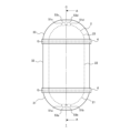
- FIG. 1 is a schematic diagram of a hot water storage tank according to Embodiment 1.
- FIG. 1 is a schematic cross-sectional view of a hot water storage tank according to Embodiment 1.
- FIG. FIG. 2 is a diagram showing a hot water storage tank and piping connected to the hot water storage tank according to the first embodiment.
- FIG. 3 is a schematic diagram showing a state in which a tape is attached according to Embodiment 1.
- FIG. FIG. 7 is a schematic diagram showing a state in which a tape is attached according to Embodiment 2;
- FIG. 7 is a schematic diagram showing a state in which a tape is attached according to Embodiment 3;
- FIG. 7 is a schematic diagram showing a state in which a tape is attached according to Embodiment 4;
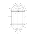
- FIG. 7 is a schematic diagram of a hot water storage tank according to Embodiment 6.
- FIG. 7 is a schematic diagram of a hot water storage tank according to Embodiment 7.
- FIG. 1 is a schematic diagram of a hot water storage tank 1 according to the first embodiment.
- FIG. 2 is a schematic cross-sectional view of the hot water storage tank 1 according to the first embodiment.
- FIG. 1 parts that cannot be visually recognized from the outside are indicated by broken lines.
- FIG. 2 shows the hot water storage tank 1 cut along the AA cross section in FIG.
- the hot water storage tank 1 of this embodiment is a cylindrical tank that stores liquid such as water or hot water.
- water refers to unheated water
- hot water refers to heated water.
- the hot water storage tank 1 includes a tank body 2 that stores liquid, a lower insulation material 31 that covers the tank body 2, a side insulation material 32, an upper insulation material 33, and a lower insulation material 31. and a tape 4 connecting the side heat insulating material 32 and the top heat insulating material 33 to the side heat insulating material 32, respectively.
- the lower heat insulating material 31, the side heat insulating material 32, and the upper heat insulating material 33 may be collectively called a heat insulating material.
- the tank body 2 has a cylindrical appearance and a hollow interior.
- the tank body 2 has a substantially symmetrical shape with respect to the central axis C.
- the tank body 2 consists of a bottom surface 21, side surfaces 22, and a top surface 23.
- the bottom surface 21 corresponds to a lower hemispherical portion of the tank body 2.
- the side surface 22 is connected to the bottom surface 21 and corresponds to a cylindrical portion that is the body of the tank body 2.
- the top surface 23 is connected to the side surface 22 and corresponds to an upper hemispherical portion of the tank body 2.
- a take-out port 51a and a take-out port 51b are formed on the bottom surface 21 of the tank body 2.
- a take-out port 51c and a take-out port 51d are formed on the top surface 23 of the tank body 2.
- FIG. 3 is a diagram showing the hot water storage tank 1 and piping connected to the hot water storage tank 1 according to the first embodiment.
- the tank body 2 is connected to a bottom pipe 52a, a water supply pipe 52b, an upper pipe 52c, and a hot water supply pipe 52d through which water or hot water flows.
- the inlet of the bottom pipe 52a is connected to the outlet 51a provided at the bottom of the tank body 2.
- the outlet of the bottom pipe 52a is connected to the heating device 9.
- the heating device 9 is a device that heats water using a heater or a heat pump.
- the inlet of the water supply pipe 52b is connected to a supply pipe (not shown) for, for example, city water.
- the outlet of the water supply pipe 52b is branched, one of which is connected to the outlet 51b provided at the bottom of the tank body 2, and the other connected to the hot water supply pipe 52d.
- the inlet of the upper pipe 52c is connected to the heating device 9.
- An outlet of the upper pipe 52c is connected to an outlet 51c provided at the upper part of the tank body 2.
- the inlet of the hot water supply pipe 52d is connected to an outlet 51d provided at the top of the tank body 2.
- the outlet of the hot water supply pipe 52d is connected to a user side pipe (not shown) or the like.
- the hot water storage tank 1 stores and releases hot water in the following manner. First, water stored in the tank body 2 is sent to the heating device 9 through the bottom pipe 52a and heated. The heated water is returned to the upper part of the tank body 2 through the upper pipe 52c. When water is supplied to the tank body 2 from the outside, water is supplied to the lower part of the tank body 2 from the water supply pipe 52b.
- the hot water stored in the tank body 2 is pushed up. Thereby, hot water is discharged to the outside from the hot water supply pipe 52d connected to the upper part of the tank body 2.
- the hot water supplied from the hot water supply pipe 52d and the water supplied from the water supply pipe 52b are mixed to generate and supply hot water at a temperature desired by the user.
- the tank body 2 Immediately after storing hot water, the tank body 2 is uniformly filled with hot water, but as time passes and the hot water is stored and dispensed, the upper part of the tank body 2 becomes hotter and the lower part becomes colder. A thermal boundary layer is formed. This is because the specific gravity of water changes depending on the temperature, and high temperature water has a lighter specific gravity.
- the tank body 2 is covered with three heat insulating materials: a lower heat insulating material 31, a side heat insulating material 32, and an upper heat insulating material 33.
- the lower insulation material 31, the side insulation material 32, and the upper insulation material 33 provide insulation between the tank body 2 and the surrounding air.
- the lower heat insulating material 31 has a hollow, substantially hemispherical shape.
- the lower heat insulating material 31 covers the bottom surface 21 of the tank body 2.
- the lower heat insulating material 31 is attached in close contact with the bottom surface 21 of the tank body 2.
- the lower heat insulating material 31 may cover a portion below the center of the side surface 22. In this case, the lower heat insulating material 31 is attached in close contact with a portion of the bottom surface 21 and side surfaces 22 of the tank body 2.
- the lower heat insulating material 31 has insertion holes 53a and 53b formed therein.
- the insertion hole 53a is a hole that communicates with the outlet 51a and through which the bottom pipe 52a is inserted.
- the insertion hole 53b communicates with the outlet 51b and is a hole through which the water supply pipe 52b is inserted.
- the side heat insulating material 32 has a hollow, substantially cylindrical shape.
- the side insulation material 32 covers the side surface 22 of the tank body 2.
- the side heat insulating material 32 is attached in close contact with the side surface 22 of the tank body 2.
- the side heat insulating material 32 may cover the entire side surface 22 of the tank body 2, or may cover the entire side surface 22 of the tank body 2, or may cover the side surface 22 above the portion covered by the lower heat insulating material 31 and above the portion covered by the top heat insulating material 33. It may also cover the lower part.
- the upper heat insulating material 33 has a hollow, substantially hemispherical shape.
- the upper heat insulating material 33 covers the top surface 23 of the tank body 2.
- the upper heat insulating material 33 is attached in close contact with the top surface 23 of the tank body 2.
- the upper heat insulating material 33 may cover a portion above the center of the side surface 22. In this case, the upper heat insulating material 33 is attached in close contact with a portion of the top surface 23 and side surfaces 22 of the tank body 2.
- Insertion holes 53c and 53d are formed in the upper heat insulating material 33.
- the insertion hole 53c communicates with the outlet 51c and is a hole through which the upper pipe 52c is inserted.
- the insertion hole 53d communicates with the outlet 51d and is a hole through which the hot water supply pipe 52d is inserted.
- the lower heat insulating material 31, the side heat insulating material 32, and the upper heat insulating material 33 are foamed heat insulating materials made of foamed polystyrene, for example.
- the lower heat insulating material 31, the side heat insulating material 32, and the upper heat insulating material 33 may be made of the same material, or may be made of different materials.
- the thermal conductivity of the upper insulating material among the vertically adjacent insulating materials is the same as that of the insulating material located on the lower side.
- the thermal conductivity of the insulation material used should be lower than that of the insulation material used. In other words, among the vertically adjacent heat insulating materials, the heat insulating performance of the heat insulating material arranged on the upper side is made higher than the heat insulating performance of the heat insulating material arranged on the lower side.
- the thermal conductivity of the side heat insulating material 32 and the top heat insulating material 33 is made smaller than that of the lower heat insulating material 31.
- the thermal conductivity of the upper insulating material 33 is made smaller than that of the lower insulating material 31 and the side insulating material 32.
- the thermal conductivity of the side insulation material 32 is made lower than that of the lower insulation material 31, and the thermal conductivity of the upper insulation material 33 is made lower than that of the side insulation material 32. Due to the temperature dependence of water density, the higher temperature water in the tank body 2 moves to the upper part by convection, so by reducing the thermal conductivity of the insulation material placed on the upper side, The top can be properly insulated.
- the upper end surface 312 of the lower insulation material 31, the lower end surface 321 and the upper end surface 322 of the side insulation material 32, and the lower end surface 331 of the upper insulation material 33 are formed substantially horizontally over the entire circumference. ing.
- the lower heat insulating material 31 is vertically adjacent to the side heat insulating material 32 , and the upper end surface 312 of the lower heat insulating material 31 faces the lower end surface 321 of the side heat insulating material 32 .
- the upper heat insulating material 33 is vertically adjacent to the side heat insulating material 32 , and the lower end surface 331 of the upper heat insulating material 33 faces the upper end surface 322 of the side heat insulating material 32 .
- the lower heat insulating material 31, the side heat insulating material 32, and the upper heat insulating material 33 have substantially the same thickness at least in adjacent portions.
- the dimensions are designed so that the lower end surface 321 of the side insulation material 32 is in contact with the upper end surface 312 of the lower insulation material 31, and the upper end surface 322 of the side insulation material 32 is in contact with the lower end surface 331 of the upper insulation material 33. has been done.
- a gap G will occur between two adjacent heat insulators. In the case of this embodiment, between the lower end surface 321 of the side insulation material 32 and the upper end surface 312 of the lower insulation material 31, or between the lower end surface 331 of the upper insulation material 33 and the upper end surface 322 of the side insulation material 32. A gap G occurs between them.
- FIG. 4 is a schematic diagram showing how the tape 4 is attached according to the first embodiment.
- the tape 4 of this embodiment covers the gap G between the heat insulating materials.
- the gap G between the lower heat insulating material 31 and the side heat insulating material 32 is covered with the tape 4.
- the gap G between the upper heat insulating material 33 and the side heat insulating material 32 is also covered with the tape 4 similarly to the gap G between the lower heat insulating material 31 and the side heat insulating material 32 shown in FIG.
- the tape 4 consists of a base material made of vinyl and an adhesive layer provided on the entire surface of the base material.
- the base material is a sheet or film, and the adhesive layer is made of a viscous adhesive.
- the gap G between the heat insulating materials is formed by extending linearly around the outside of the tank body 2 in the circumferential direction.
- the tape 4 extends parallel to the gap G whose long sides extend in the circumferential direction, and is attached to the adjacent heat insulating material.
- the direction parallel to the short side of the tape 4 is defined as the short side direction, and in the case of FIGS. 1, 2, and 4, the short side direction is the vertical direction when the hot water storage tank 1 is installed.
- the direction parallel to the long side of the tape 4 is defined as the long side direction, and in the case of FIGS. 1, 2, and 4, the long side direction of the tape 4 is the circumferential direction of the tank body 2.
- the tape 4 is attached to the ends of two adjacent heat insulating materials among the plurality of heat insulating materials so as to overlap each other.
- the two adjacent heat insulating materials are the lower heat insulating material 31 and the side heat insulating material 32, and the upper heat insulating material 33 and the side heat insulating material 32.
- the tape 4 covering the gap G between the lower insulation material 31 and the side insulation material 32 is pasted so as to overlap the upper end of the lower insulation material 31 and the lower end of the side insulation material 32. .
- the tape 4 covering the gap G between the upper heat insulating material 33 and the side heat insulating material 32 is attached so as to overlap the upper end of the side heat insulating material 32 and the lower end of the upper heat insulating material 33.
- the tape 4 connects the lower insulation material 31 and the side insulation material 32, and the upper insulation material 33 and the side insulation material 32, respectively.
- a step also occurs between two adjacent heat insulating materials.
- wrinkles occur in the tape 4 due to the difference in level between the heat insulating materials.
- the wrinkles of the tape 4 reach from the gap G to the end of the tape 4 in the short side direction, convection will occur from the surface of the tank body 2 to the outside of the heat insulating material through the gap G and the wrinkles. Therefore, in the tape 4 of the present embodiment, one of the adjacent heat insulating materials and the tape 4 are in continuous contact with each other, and the tape 4 and the other heat insulating material are in continuous contact with each other in the long side direction.
- the tape 4 is pasted so that the non-adhesion region R2 shown in FIG. .
- the width of the tape 4 in the short side direction is set to be at least three times the width of the gap G when dimensional variations within the tolerance range occur.
- the gap G between adjacent heat insulating materials is covered with the tape 4, and within the width of the tape 4 in the short side direction, one of the adjacent heat insulating materials is covered in parallel with the gap G.
- the material and the tape 4, and the other heat insulating material and the tape 4 are continuously brought into close contact with each other.
- generation of convection from the surface of the tank body 2 to the outside of the heat insulating material is prevented, and heat radiation from the tank body 2 can be suppressed.
- parallel to the gap G includes not only the case of being strictly parallel to the gap G but also the case of being substantially parallel to the gap G.
- FIG. 5 is a schematic diagram showing a state in which the tape 4A according to the second embodiment is attached.
- the second embodiment differs from the first embodiment in the material of the tape 4A.
- the rest of the configuration of the hot water storage tank 1 in the second embodiment is the same as in the first embodiment, and the differences from the first embodiment will be mainly described below.
- the tape 4A of this embodiment is made of a flexible material or is thin.
- the base material of the tape 4A is made of a flexible material or the thickness of the base material is made thin so that the adhesive strength is stronger than the bending stress of the base material when the tape 4A is bent.
- Shore A hardness when flexibility is indicated by Shore A hardness, the Shore A hardness of the base material of tape 4A is within the range of 50 to 100.
- the material of the base material of the tape 4A polyolefin (PO), polyethylene (PE), flexible vinyl chloride (PVC), Damplon (OPP), polyester (PET), polyimide (PI), or cellophane is used.
- the thickness of the tape 4A is approximately 0.2 mm or less.
- the tape 4A By making the tape 4A flexible, even if the tape 4A is partially lifted from the insulation material due to wrinkles caused by the step between the insulation materials, the operator can push out the air inside the wrinkles to remove the lifted tape 4A. can be attached to the insulation material. Further, the tapes 4A can be partially attached to each other in a mountain-fold manner without any gaps. As a result, as shown in FIG. 5, it is possible to eliminate wrinkles in the tape 4A, reduce the non-adhesion region R2, and enlarge the adhesion region R1.
- the operator can Wrinkles can be easily removed with your nails.
- one of the adjacent heat insulating materials and the tape 4A, and the other heat insulating material and the tape 4A can be brought into continuous contact with each other.
- generation of convection from the surface of the tank body 2 to the outside of the heat insulating material is prevented, and heat radiation from the tank body 2 can be suppressed.
- the wrinkles of the tape 4A can be eliminated to form the close contact region R1, the width of the tape 4A in the short side direction can be made smaller than in the first embodiment.
- FIG. 6 is a schematic diagram showing a state in which the tape 4B according to the third embodiment is attached.
- Embodiment 3 differs from Embodiment 1 in the configuration of tape 4B.
- the rest of the configuration of the hot water storage tank 1 in the third embodiment is the same as in the first embodiment, and the differences from the first embodiment will be mainly explained.
- the adhesive layer 41 of the tape 4B of this embodiment is provided only at both ends in the short side direction. In other words, the adhesive layer 41 is not provided at the center of the tape 4B in the short side direction, that is, at the portion facing the gap G.
- the width of each adhesive layer 41 of the tape 4B is, for example, 1/3 or less of the width of the tape 4A in the short side direction.
- the adhesive layer 41 is not provided.
- the tape 4B provided with the adhesive layer 41 can be brought into close contact with the heat insulating material without forming wrinkles at both ends in the short side direction.
- generation of convection from the surface of the tank body 2 to the outside of the heat insulating material is prevented, and heat radiation from the tank body 2 can be suppressed.
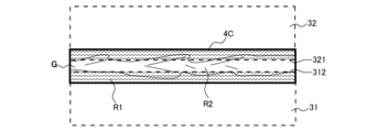
- FIG. 7 is a schematic diagram showing a state in which the tape 4C according to the fourth embodiment is attached.
- Embodiment 4 differs from Embodiment 1 in the material of tape 4C.
- the rest of the configuration of the hot water storage tank 1 in the fourth embodiment is the same as in the first embodiment, and the explanation will focus on the differences from the first embodiment.
- the tape 4C of the third embodiment is made of a stretchable material.
- a material having an "elongation" of 100% or more according to the JIS Z2037 test standard is used as the tape 4C.
- polyolefin (PO), polyethylene (PE), vinyl chloride (PVC), Danprone (OPP), or the like is used as a material having extensibility for the tape 4C.
- the tape 4C By composing the tape 4C with a stretchable material, even if the tape 4C wrinkles due to a step between the insulation materials caused by dimensional variations and the tape 4C is partially lifted from the insulation material, the tape 4C It is possible to partially extend the material to follow the step and make it fit closely. Thereby, the tape 4C and the outer circumferential surface of the heat insulating material (in the case of FIG. 7, the lower heat insulating material 31 and the side heat insulating material 32) can be brought into close contact. Further, in this embodiment, as shown in FIG. 7, the non-adhesive region R2 can be made only in the gap G, and the entire pasted part of the tape 4C with the heat insulating material can be the adhesion region R1.
- the tape 4C it is possible to partially extend the material to follow the step and make it fit closely. As a result, generation of convection from the surface of the tank body 2 to the outside of the heat insulating material is prevented, and heat radiation from the tank body 2 can be suppressed.
- Embodiment 5 will be described.
- the fifth embodiment differs from the first embodiment in the material of the tape 4.
- the rest of the configuration of the hot water storage tank 1 in the fifth embodiment is the same as that in the first embodiment, and the explanation will focus on the differences from the first embodiment.
- the tape 4 of this embodiment is made of a heat-shrinkable material such as a heat-shrinkable film.
- the upper end of the tape 4 in the short side direction is fixed so as to cover the lower end of the upper insulating material 33, and the lower end of the tape 4 in the short side direction is fixed to the side insulating material 32. Fix it so that it covers the top edge.
- the tape 4 contracts due to the heat of the hot water in the tank body 2, and the surface of the heat insulating material covered by the tape 4 is It follows the shape and adheres closely.
- the state of application of the tape 4 at the time of pasting is the same as the state of application of the tape 4B shown in FIG. 6, and the state of application of the tape 4 after heat shrinkage is the same as the state of application of the tape 4C shown in FIG. .
- the tape 4 can be made to follow the step and adhere tightly by thermal contraction. As a result, generation of convection from the surface of the tank body 2 to the outside of the heat insulating material is prevented, and heat radiation from the tank body 2 can be suppressed.
- FIG. 8 is a schematic diagram of a hot water storage tank 1A according to the sixth embodiment.
- Embodiment 6 differs from Embodiment 1 in the method of applying tape 4.
- the rest of the configuration of the hot water storage tank 1A in the sixth embodiment is the same as in the first embodiment, and the differences from the first embodiment will be mainly explained.
- the tape 4 of this embodiment has an overlapping region R3 that is pasted overlappingly.
- the overlapping region R3 is formed by shifting the start position P1 and the end position P2 of pasting the tape 4 in the long side direction.
- the overlapping region R3 is provided to cover a portion where the difference in level between the heat insulating materials is large.
- a fitting part 30 having an uneven shape for fitting is formed at the lower end of the upper insulating material 33 and the upper end of the side insulating material 32, and the fitting part 30 is formed by the overlapping region R3 of the tape 4. Covered.
- the tape 4 sets the position in front of the fitting part 30 as the starting position P1, and the pasting is started from the starting position P1. Then, the tape 4 covers the fitting part 30 and is wound in the circumferential direction parallel to the gap G, and again covers the fitting part 30, and the pasting is completed at the end position P2.
- the overlapping region R3 is not limited to one formed by overlapping the start and end portions of one tape 4. For example, after covering the gap G around the entire circumference of the tank body 2 with the tape 4, the cut tape 4 may be pasted over the fitting portion 30 to form the overlapping region R3.
- the tapes 4 are overlapped and pasted to cover the generated wrinkles with the overlapped tape 4. be able to.
- one of the adjacent heat insulating materials and the tape 4 and the other heat insulating material and the tape 4 can be brought into continuous and close contact with each other.
- generation of convection from the surface of the tank body 2 to the outside of the heat insulating material is prevented, and heat radiation from the tank body 2 can be suppressed.
- FIG. 9 is a schematic diagram of a hot water storage tank 1B according to the seventh embodiment.
- Embodiment 7 differs from Embodiment 6 in the structure of the heat insulating material.
- the rest of the configuration of the hot water storage tank 1B in the seventh embodiment is the same as that in the sixth embodiment, and the differences from the sixth embodiment will be mainly described.
- the upper heat insulating material 33 of this embodiment has a guide portion 35 that indicates the position where the tape 4 is attached.
- the guide portion 35 is formed by a minute recess or protrusion.
- a guide portion 35 consisting of a plurality of rectangular convex portions parallel to the long side direction of the tape 4 is located between the start position P1 in front of the fitting portion 30 of the upper heat insulating material 33 and the end position P2. is formed. The operator starts pasting the tape 4 by aligning the upper end of the tape 4 in the short side direction with the guide part 35, wraps around the outer circumference of the tank body 2, and continues pasting the tape 4 until it reaches the end position P2 indicated by the guide part 35.
- the tape 4 can be easily attached to an appropriate position while providing the overlapping region R3 that covers the fitting part 30. As a result, generation of convection from the surface of the tank body 2 to the outside of the heat insulating material is prevented, and heat radiation from the tank body 2 can be suppressed.
- the configuration of the guide portion 35 is not limited to the example shown in FIG. 9.
- the guide portions 35 may be arranged continuously in the circumferential direction, or a plurality of guide portions 35 may be arranged intermittently in the circumferential direction.
- the guide portion 35 is not limited to being formed by a concave portion or a convex portion, and may be formed by printing or the like.
- the upper heat insulating material 33 is configured to include the guide portion 35, but either one or both of the two adjacent heat insulating materials may be provided with the guide portion 35.
- the guide portion 35 is arranged outside the tape 4 application position, but the guide portion 35 may be arranged inside the tape 4 application position. Furthermore, a part of the fitting part 30 may be used as the guide part 35. In this case, the line at the upper end of the fitting part 30 is used as the guide part 35, and the tape 4 is pasted with the line and the upper end of the tape 4 in the short side direction aligned.
- any of the tapes 4, 4A to 4C of the first to fifth embodiments may be used.
- the guide portion 35 of Embodiment 7 may be provided.
- foamed polystyrene is used as the material of the heat insulating material
- foams made of foamed polypropylene, foamed urethane, polyethylene, rubber, polymer, etc. may also be used.
- the plurality of heat insulating materials that cover the tank body 2 are not limited to the three, the lower heat insulating material 31, the side heat insulating material 32, and the upper heat insulating material 33.
- at least one of the lower heat insulating material 31, the side heat insulating material 32, and the upper heat insulating material 33 may be further divided in the vertical direction, the front-back direction, or the left-right direction. This improves assembly, storage, and yield.
- the plurality of heat insulating materials that cover the tank body 2 may be two, the lower heat insulating material 31 and the upper heat insulating material 33.
- the plurality of heat insulating materials covering the tank body 2 may be two: a front heat insulating material covering the front half of the hot water storage tank 1 and a rear heat insulating material covering the rear half of the hot water storage tank 1.
- the tape 4 is not limited to being attached along the circumferential direction of the tank body 2, but may be attached vertically or diagonally in order to cover the gap G between the heat insulating materials.
Landscapes
- Engineering & Computer Science (AREA)
- Physics & Mathematics (AREA)
- Thermal Sciences (AREA)
- Chemical & Material Sciences (AREA)
- Combustion & Propulsion (AREA)
- Mechanical Engineering (AREA)
- General Engineering & Computer Science (AREA)
- Details Of Fluid Heaters (AREA)
Priority Applications (2)
| Application Number | Priority Date | Filing Date | Title |
|---|---|---|---|
| JP2024513666A JP7724952B2 (ja) | 2022-04-08 | 2022-04-08 | 貯湯タンク |
| PCT/JP2022/017360 WO2023195156A1 (ja) | 2022-04-08 | 2022-04-08 | 貯湯タンク |
Applications Claiming Priority (1)
| Application Number | Priority Date | Filing Date | Title |
|---|---|---|---|
| PCT/JP2022/017360 WO2023195156A1 (ja) | 2022-04-08 | 2022-04-08 | 貯湯タンク |
Publications (1)
| Publication Number | Publication Date |
|---|---|
| WO2023195156A1 true WO2023195156A1 (ja) | 2023-10-12 |
Family
ID=88242823
Family Applications (1)
| Application Number | Title | Priority Date | Filing Date |
|---|---|---|---|
| PCT/JP2022/017360 Ceased WO2023195156A1 (ja) | 2022-04-08 | 2022-04-08 | 貯湯タンク |
Country Status (2)
| Country | Link |
|---|---|
| JP (1) | JP7724952B2 (https=) |
| WO (1) | WO2023195156A1 (https=) |
Citations (5)
| Publication number | Priority date | Publication date | Assignee | Title |
|---|---|---|---|---|
| JP2009299760A (ja) * | 2008-06-12 | 2009-12-24 | Imae Kogyo Kk | 熱機器の断熱装置 |
| JP2015108470A (ja) * | 2013-12-04 | 2015-06-11 | 三菱電機株式会社 | 貯湯式給湯機 |
| KR20180072957A (ko) * | 2016-12-22 | 2018-07-02 | 한국지역난방공사 | 열손실 방지가 가능한 지역난방용 2차측 배관의 단열 보온재 |
| US20180292107A1 (en) * | 2014-11-03 | 2018-10-11 | Professional Trade Manufacturing, LLC | Insulating Shell for 2.1 Gallon Thermal Expansion Tanks for Potable Water Systems |
| JP2020176758A (ja) * | 2019-04-17 | 2020-10-29 | 三菱電機株式会社 | 貯湯式給湯機 |
-
2022
- 2022-04-08 WO PCT/JP2022/017360 patent/WO2023195156A1/ja not_active Ceased
- 2022-04-08 JP JP2024513666A patent/JP7724952B2/ja active Active
Patent Citations (5)
| Publication number | Priority date | Publication date | Assignee | Title |
|---|---|---|---|---|
| JP2009299760A (ja) * | 2008-06-12 | 2009-12-24 | Imae Kogyo Kk | 熱機器の断熱装置 |
| JP2015108470A (ja) * | 2013-12-04 | 2015-06-11 | 三菱電機株式会社 | 貯湯式給湯機 |
| US20180292107A1 (en) * | 2014-11-03 | 2018-10-11 | Professional Trade Manufacturing, LLC | Insulating Shell for 2.1 Gallon Thermal Expansion Tanks for Potable Water Systems |
| KR20180072957A (ko) * | 2016-12-22 | 2018-07-02 | 한국지역난방공사 | 열손실 방지가 가능한 지역난방용 2차측 배관의 단열 보온재 |
| JP2020176758A (ja) * | 2019-04-17 | 2020-10-29 | 三菱電機株式会社 | 貯湯式給湯機 |
Also Published As
| Publication number | Publication date |
|---|---|
| JP7724952B2 (ja) | 2025-08-18 |
| JPWO2023195156A1 (https=) | 2023-10-12 |
Similar Documents
| Publication | Publication Date | Title |
|---|---|---|
| JP2012163258A (ja) | 貯湯式給湯装置 | |
| JP2013221643A (ja) | 貯液ユニットおよび給湯装置 | |
| WO2023195156A1 (ja) | 貯湯タンク | |
| US10892073B2 (en) | Heatable motor vehicle operating liquid tank and method of producing the heating device for it | |
| JP2004197960A (ja) | 貯湯タンクおよび貯湯タンク用成型断熱材 | |
| US20060165970A1 (en) | Thermal insulation foamed sheet, thermal insulation foamed container and method for producing the same | |
| JP2017009216A (ja) | 貯湯タンクの断熱構造 | |
| JP2001232734A (ja) | 断熱性積層シートと該積層シートを用いた断熱カップ | |
| NL1044428B1 (en) | Radiant heat module with pcm | |
| JP7177903B2 (ja) | 冷蔵庫 | |
| JP6707066B2 (ja) | 冷蔵庫 | |
| JP2003194355A (ja) | 床暖房パネル | |
| KR101914058B1 (ko) | 코팅 알루미늄 필름층을 가지는 고무발포 보온재와 그 제조 방법 및 장치 | |
| JP7677814B2 (ja) | 継手保温カバー及びその製造方法 | |
| KR101870628B1 (ko) | 단열성능이 우수한 콘크리트 구조물을 이루는 단열부재 및 그 제작방법 | |
| CN108507162B (zh) | 电热水器 | |
| JP6349655B2 (ja) | 断熱性容器 | |
| CN206583076U (zh) | 电热水器 | |
| JP7063974B2 (ja) | 冷蔵庫 | |
| JP6685253B2 (ja) | 断熱機器、貯湯タンクおよび給湯装置 | |
| JPH11314628A (ja) | 容 器 | |
| CN221828107U (zh) | 一种电池单体及电池组 | |
| JP2003279057A (ja) | 温水式床暖房フロア用の温水パイプユニット | |
| JPH10275676A (ja) | 面状発熱体 | |
| WO2022190292A1 (ja) | 貯湯式給湯機及びその生産方法 |
Legal Events
| Date | Code | Title | Description |
|---|---|---|---|
| 121 | Ep: the epo has been informed by wipo that ep was designated in this application |
Ref document number: 22936554 Country of ref document: EP Kind code of ref document: A1 |
|
| WWE | Wipo information: entry into national phase |
Ref document number: 2024513666 Country of ref document: JP |
|
| NENP | Non-entry into the national phase |
Ref country code: DE |
|
| 122 | Ep: pct application non-entry in european phase |
Ref document number: 22936554 Country of ref document: EP Kind code of ref document: A1 |