WO2023191007A1 - 換気装置及び換気方法 - Google Patents
換気装置及び換気方法 Download PDFInfo
- Publication number
- WO2023191007A1 WO2023191007A1 PCT/JP2023/013425 JP2023013425W WO2023191007A1 WO 2023191007 A1 WO2023191007 A1 WO 2023191007A1 JP 2023013425 W JP2023013425 W JP 2023013425W WO 2023191007 A1 WO2023191007 A1 WO 2023191007A1
- Authority
- WO
- WIPO (PCT)
- Prior art keywords
- heat exchanger
- temperature
- refrigerant
- air
- ventilation device
- Prior art date
- Legal status (The legal status is an assumption and is not a legal conclusion. Google has not performed a legal analysis and makes no representation as to the accuracy of the status listed.)
- Ceased
Links
Images











Classifications
-
- F—MECHANICAL ENGINEERING; LIGHTING; HEATING; WEAPONS; BLASTING
- F24—HEATING; RANGES; VENTILATING
- F24F—AIR-CONDITIONING; AIR-HUMIDIFICATION; VENTILATION; USE OF AIR CURRENTS FOR SCREENING
- F24F1/00—Room units for air-conditioning, e.g. separate or self-contained units or units receiving primary air from a central station
- F24F1/0007—Indoor units, e.g. fan coil units
- F24F1/0035—Indoor units, e.g. fan coil units characterised by introduction of outside air to the room
- F24F1/0038—Indoor units, e.g. fan coil units characterised by introduction of outside air to the room in combination with simultaneous exhaustion of inside air
-
- F—MECHANICAL ENGINEERING; LIGHTING; HEATING; WEAPONS; BLASTING
- F24—HEATING; RANGES; VENTILATING
- F24F—AIR-CONDITIONING; AIR-HUMIDIFICATION; VENTILATION; USE OF AIR CURRENTS FOR SCREENING
- F24F11/00—Control or safety arrangements
- F24F11/30—Control or safety arrangements for purposes related to the operation of the system, e.g. for safety or monitoring
- F24F11/46—Improving electric energy efficiency or saving
-
- F—MECHANICAL ENGINEERING; LIGHTING; HEATING; WEAPONS; BLASTING
- F24—HEATING; RANGES; VENTILATING
- F24F—AIR-CONDITIONING; AIR-HUMIDIFICATION; VENTILATION; USE OF AIR CURRENTS FOR SCREENING
- F24F11/00—Control or safety arrangements
- F24F11/70—Control systems characterised by their outputs; Constructional details thereof
- F24F11/80—Control systems characterised by their outputs; Constructional details thereof for controlling the temperature of the supplied air
- F24F11/87—Control systems characterised by their outputs; Constructional details thereof for controlling the temperature of the supplied air by controlling absorption or discharge of heat in outdoor units
-
- F—MECHANICAL ENGINEERING; LIGHTING; HEATING; WEAPONS; BLASTING
- F24—HEATING; RANGES; VENTILATING
- F24F—AIR-CONDITIONING; AIR-HUMIDIFICATION; VENTILATION; USE OF AIR CURRENTS FOR SCREENING
- F24F7/00—Ventilation
- F24F7/04—Ventilation with ducting systems, e.g. by double walls; with natural circulation
- F24F7/06—Ventilation with ducting systems, e.g. by double walls; with natural circulation with forced air circulation, e.g. by fan positioning of a ventilator in or against a conduit
- F24F7/08—Ventilation with ducting systems, e.g. by double walls; with natural circulation with forced air circulation, e.g. by fan positioning of a ventilator in or against a conduit with separate ducts for supplied and exhausted air with provisions for reversal of the input and output systems
-
- F—MECHANICAL ENGINEERING; LIGHTING; HEATING; WEAPONS; BLASTING
- F24—HEATING; RANGES; VENTILATING
- F24F—AIR-CONDITIONING; AIR-HUMIDIFICATION; VENTILATION; USE OF AIR CURRENTS FOR SCREENING
- F24F2110/00—Control inputs relating to air properties
- F24F2110/10—Temperature
-
- F—MECHANICAL ENGINEERING; LIGHTING; HEATING; WEAPONS; BLASTING
- F24—HEATING; RANGES; VENTILATING
- F24F—AIR-CONDITIONING; AIR-HUMIDIFICATION; VENTILATION; USE OF AIR CURRENTS FOR SCREENING
- F24F2110/00—Control inputs relating to air properties
- F24F2110/10—Temperature
- F24F2110/12—Temperature of the outside air
-
- F—MECHANICAL ENGINEERING; LIGHTING; HEATING; WEAPONS; BLASTING
- F24—HEATING; RANGES; VENTILATING
- F24F—AIR-CONDITIONING; AIR-HUMIDIFICATION; VENTILATION; USE OF AIR CURRENTS FOR SCREENING
- F24F2110/00—Control inputs relating to air properties
- F24F2110/50—Air quality properties
- F24F2110/64—Airborne particle content
-
- F—MECHANICAL ENGINEERING; LIGHTING; HEATING; WEAPONS; BLASTING
- F24—HEATING; RANGES; VENTILATING
- F24F—AIR-CONDITIONING; AIR-HUMIDIFICATION; VENTILATION; USE OF AIR CURRENTS FOR SCREENING
- F24F2110/00—Control inputs relating to air properties
- F24F2110/50—Air quality properties
- F24F2110/65—Concentration of specific substances or contaminants
- F24F2110/70—Carbon dioxide
-
- F—MECHANICAL ENGINEERING; LIGHTING; HEATING; WEAPONS; BLASTING
- F24—HEATING; RANGES; VENTILATING
- F24F—AIR-CONDITIONING; AIR-HUMIDIFICATION; VENTILATION; USE OF AIR CURRENTS FOR SCREENING
- F24F2140/00—Control inputs relating to system states
- F24F2140/10—Pressure
- F24F2140/12—Heat-exchange fluid pressure
-
- F—MECHANICAL ENGINEERING; LIGHTING; HEATING; WEAPONS; BLASTING
- F24—HEATING; RANGES; VENTILATING
- F24F—AIR-CONDITIONING; AIR-HUMIDIFICATION; VENTILATION; USE OF AIR CURRENTS FOR SCREENING
- F24F2140/00—Control inputs relating to system states
- F24F2140/20—Heat-exchange fluid temperature
Definitions
- the present disclosure relates to a ventilation device and a ventilation method.
- Patent Document 1 discloses an air conditioning equipment that air-conditions an indoor space by adjusting air introduced from the outside.
- a refrigeration circuit included in the air conditioning equipment has a compression means, a first heat exchanger, a liquid receiver, an expansion valve, and a second heat exchanger connected through piping, and a refrigerant circulates inside. It is disclosed that the apparatus is configured to perform a refrigeration cycle.
- the air conditioning equipment includes a dispersing means for dispersing condensed water (drain water) generated on the outer surface of the second heat exchanger onto the outer surface of the first heat exchanger during dehumidification operation. This is disclosed.
- the amount of air exhausted and the amount of air supplied are equal, so it is necessary to adjust the temperature using the refrigerant circuit.
- the present disclosure provides a ventilation device and a ventilation method that efficiently exhaust heat in a heat exchanger.
- This disclosure a compressor; a first heat exchanger provided in a first path through which outdoor air is supplied indoors and through which the first air passes; a second heat exchanger provided in a second path through which the indoor air is exhausted to the outdoors, and through which the second air passes; a refrigerant circuit in which the compressor, the first heat exchanger, and the second heat exchanger are connected by refrigerant piping, and a refrigerant flows inside; a spraying unit that is supplied with liquid from the outside and that sprays the cooling liquid onto the second heat exchanger; Equipped with It is a ventilation device.
- exhaust heat in the exhaust heat exchanger can be efficiently exhausted.
- the ventilation device of the present disclosure further includes a control unit that controls the spray unit to spray the cooling liquid to the second heat exchanger based on a physical quantity correlated to the condensation temperature in the second heat exchanger. It's okay.
- the physical quantity includes a first temperature of the refrigerant flowing into the second heat exchanger, a second temperature of the refrigerant flowing out from the second heat exchanger, and a temperature of the refrigerant flowing into the second heat exchanger.
- the temperature may be at least one of a fifth temperature of the refrigerant discharged from the compressor and a third pressure of the refrigerant discharged from the compressor.
- control unit calculates the condensation temperature in the second heat exchanger from the physical quantity, and when the condensation temperature is equal to or higher than a preset target temperature, the control unit calculates the condensation temperature in the second heat exchanger from the physical quantity.
- the spraying section may be controlled to spray the cooling liquid.
- control unit may control the amount of the cooling liquid sprayed from the spray unit based on the difference between the condensation temperature and the target temperature.
- a compressor a first heat exchanger provided in a first path through which outdoor air is supplied indoors and through which the first air passes; a second heat exchanger provided in a second path through which the indoor air is exhausted to the outdoors, and through which the second air passes; a refrigerant circuit in which the compressor, the first heat exchanger, and the second heat exchanger are connected by refrigerant piping, and a refrigerant flows inside; An absorbent material is provided upstream of the second heat exchanger in the second path, through which the second air passes, absorbs and holds the liquid inside, and discharges the held liquid from the inside to the outside.
- a cooling unit that cools the second air by heat of vaporization when the liquid is formed and discharged to the outside; a spraying section that sprays a cooling liquid to the cooling section; Equipped with Ventilation equipment.
- exhaust heat in the exhaust heat exchanger can be efficiently exhausted.
- the ventilation device of the present disclosure further includes a control unit that controls the spray unit to spray the cooling liquid to the second heat exchanger based on a physical quantity correlated to the condensation temperature in the second heat exchanger. It's okay.
- the physical quantity includes a first temperature of the refrigerant flowing into the second heat exchanger, a second temperature of the refrigerant flowing out from the second heat exchanger, and a temperature of the refrigerant flowing into the second heat exchanger.
- the temperature may be at least one of a fifth temperature of the refrigerant discharged from the compressor and a third pressure of the refrigerant discharged from the compressor.
- control unit calculates the condensation temperature in the second heat exchanger from the physical quantity, and when the condensation temperature is equal to or higher than a preset target temperature, the control unit causes the cooling unit to The spraying section may be controlled to spray the liquid.
- control unit may control the amount of the cooling liquid sprayed from the spray unit based on the difference between the condensation temperature and the target temperature.
- first temperature detection that measures either a sixth temperature of the refrigerant supplied to the second heat exchanger or a seventh temperature of the refrigerant discharged from the second heat exchanger.
- the control unit may further include a device, and the control unit may calculate the condensation temperature based on the measurement result of the first temperature detector.
- the ventilation device of the present disclosure further includes a second temperature detector that measures an eighth temperature of the refrigerant discharged from the compressor to the second heat exchanger, and the control unit is configured to detect the second temperature detector.
- the condensation temperature may be calculated based on the measurement results.
- control unit may control a sixth temperature of the refrigerant supplied to the second heat exchanger, a seventh temperature of the refrigerant discharged from the second heat exchanger, and a third temperature of the refrigerant discharged from the second heat exchanger.
- first learning data for any of the eighth temperatures of the refrigerant discharged to the second heat exchanger; acquiring second learning data for the flow rate of the coolant sprayed by the spray unit; a first prediction model that predicts how much the condensation temperature will fall from one of the sixth temperature, the seventh temperature, and the eighth temperature and the flow rate, based on the first learning data and the second learning data; is learned, and based on the first prediction model, the temperature of the cooling liquid to be sprayed from the spray section is determined based on any one of the sixth temperature, the seventh temperature, and the eighth temperature used for learning and the condensation temperature.
- the flow rate may also be calculated.
- the second heat exchanger includes an internal pipe through which the refrigerant flows, a fin connected to the internal pipe, and the cooling liquid formed on the surface of the fin and sprayed from the spray section. a liquid holding part formed of a water absorbing material capable of absorbing and holding the coolant inside and discharging the held coolant from the inside to the outside, the second heat exchanger
- the refrigerant may be cooled by evaporation of the cooling liquid.
- the ventilation device of the present disclosure may further include a third heat exchanger provided upstream of the second heat exchanger in the second path and connected to the refrigerant circuit.
- a fourth heat exchanger provided downstream of the second heat exchanger in the second path and connected to the refrigerant circuit; the second heat exchanger and the fourth heat exchanger;
- the heat exchanger may further include a second spraying section that is provided between the heat exchanger and the fourth heat exchanger and sprays the second cooling liquid onto the fourth heat exchanger.
- a fourth heat exchanger provided downstream of the second heat exchanger in the second path and connected to the refrigerant circuit; the second heat exchanger and the fourth heat exchanger; It is formed by a water absorbing material that is provided between the exchanger and the second air passes through, absorbs and holds water inside, and discharges the held water from the inside to the outside, and the water is discharged to the outside.
- the air conditioner may further include a second cooling section that cools the second air using heat of vaporization when it is discharged, and a second spray section that sprays a second cooling liquid onto the second cooling section.
- a compressor a first heat exchanger provided in a first path through which outdoor air is supplied indoors and through which the first air passes, and a first heat exchanger provided in a second path through which the indoor air is exhausted outdoors.
- a ventilation device comprising: a second heat exchanger through which second air passes; and a refrigerant circuit in which the compressor, the first heat exchanger, and the second heat exchanger are connected by refrigerant piping, and a refrigerant flows inside.
- exhaust heat in the exhaust heat exchanger can be efficiently exhausted.
- a compressor a first heat exchanger provided in a first path through which outdoor air is supplied indoors and through which the first air passes, and a first heat exchanger provided in a second path through which the indoor air is exhausted outdoors.
- a second heat exchanger through which second air passes a refrigerant circuit in which the compressor, the first heat exchanger, and the second heat exchanger are connected by refrigerant piping; and a refrigerant circuit through which the refrigerant flows; and the second path.
- the second heat exchanger is formed of a water absorbing material that is provided upstream of the second heat exchanger, through which the second air passes, absorbs and holds water inside, and discharges the held water from the inside to the outside;
- a ventilation method using a ventilation device comprising: a cooling unit that cools the second air using heat of vaporization when water is discharged to the outside; a step of spraying a cooling liquid into the cooling section; This is a ventilation method.
- exhaust heat in the exhaust heat exchanger can be efficiently exhausted.
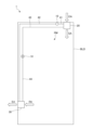
- FIG. 1 is a plan view illustrating how the ventilation device according to the first embodiment is used.
- FIG. 2 is a side view illustrating how the ventilation device according to the first embodiment is used.
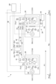
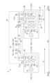
- FIG. 3 is a diagram showing a schematic configuration of the ventilation device according to the first embodiment.
- FIG. 4 is a functional block diagram of the ventilation device according to the first embodiment.
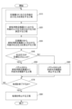
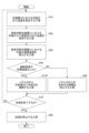
- FIG. 5 is a flowchart showing the processing of the ventilation device according to the first embodiment.
- FIG. 6 is a flowchart showing the processing of the ventilation device according to the first embodiment.
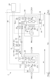
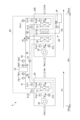
- FIG. 7 is a diagram showing a schematic configuration of a ventilation device according to a second embodiment.
- FIG. 8 is a flowchart showing the processing of the ventilation device according to the second embodiment.
- FIG. 1 is a plan view illustrating how the ventilation device according to the first embodiment is used.
- FIG. 2 is a side view illustrating how the ventilation device according to the first embodiment is used.
- FIG. 3 is a diagram showing a schematic configuration of the ventilation
- FIG. 9 is a flowchart showing the processing of the ventilation device according to the second embodiment.
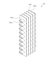
- FIG. 10 is a diagram schematically showing a heat exchanger of a ventilation system according to this embodiment.
- FIG. 11 is a diagram showing a schematic configuration of a ventilation device according to a third embodiment.
- FIG. 12 is a diagram showing a schematic configuration of a ventilation device according to a fourth embodiment.
- FIG. 13 is a diagram showing a schematic configuration of a ventilation device according to a fifth embodiment.
- FIG. 14 is a diagram showing a schematic configuration of a ventilation device according to a sixth embodiment.
- FIG. 15 is a flowchart showing the processing of the ventilation device according to the seventh embodiment.
- FIG. 16 is a flowchart showing the processing of the ventilation device according to the seventh embodiment.
- FIG. 17 is a diagram showing a schematic configuration of a ventilation device according to the eighth embodiment.
- FIG. 18 is a diagram schematically showing an exhaust unit of a ventilation system according to the eighth embodiment.
- FIG. 19 is a diagram illustrating the operation of the ventilation device according to the eighth embodiment.
- FIG. 20 is a diagram schematically showing a modification of the exhaust unit of the ventilation system according to the eighth embodiment.
- FIG. 21 is a diagram schematically showing a water spray section included in the ventilation device according to the present embodiment.
- FIG. 22 is a diagram schematically showing a modification of the water spray section included in the ventilation device according to the present embodiment.
- FIG. 23 is a diagram schematically showing a modification of the exhaust unit included in the ventilation apparatus according to the present embodiment.
- FIG. 24 is a diagram showing the functional configuration of the ventilation device according to this embodiment.
- FIG. 1 is a diagram illustrating the usage state of the ventilation device 1 according to the present embodiment in a plan view.
- FIG. 2 is a side view illustrating how the ventilation device 1 according to the present embodiment is used.
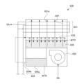
- FIG. 3 is a diagram showing a schematic configuration of the ventilation device 1 according to this embodiment.
- the ventilation device 1 includes a compressor 10, an air supply unit 20, and an exhaust unit 30. Further, the ventilation device 1 includes a refrigerant pipe 41, a refrigerant pipe 42, a refrigerant pipe 43, a refrigerant pipe 44, and an expansion valve 51. Further, the ventilation device 1 includes a control unit 60 that controls the entire ventilation device 1. Note that the compressor 10, the air supply heat exchanger 21 of the air supply unit 20 described later, the exhaust heat exchanger 31 of the exhaust unit 30 described later, the refrigerant pipe 41, the refrigerant pipe 42, the refrigerant pipe 43, and the refrigerant The piping 44 and the expansion valve 51 may be collectively referred to as a refrigerant circuit 50.
- the air that the air supply unit 20 takes in from outside the building BLD is referred to as outdoor air (OA).
- the air that the air supply unit 20 sends into the interior of the building BLD is referred to as supply air SA (SA: Supply Air).
- SA Supply Air
- RA return air RA
- EA exhaust air
- refrigerant R1 and refrigerant R2 are the same refrigerant.
- the same refrigerant is shown differentiated into refrigerant R1 and refrigerant R2 based on the difference in pressure before and after the expansion valve 51.
- FIG. 3 shows how the ventilation system 1 is used in summer. That is, the exhaust heat exchanger 31 acts as a condenser to cool the refrigerant R1 with the return air RA. Then, the air supply heat exchanger 21 acts as an evaporator to cool the outside air OA using the refrigerant R2 obtained by reducing the pressure of the cooled refrigerant R1.
- the directions of the arrowed lines of the refrigerant R1 and the refrigerant R2 indicate the flow directions of the refrigerant R1 and the refrigerant R2 when the refrigerant compressed by the compressor 10 is supplied to the exhaust unit 30.
- the air supply unit 20 of the ventilation system 1 is provided on the ceiling of the room RM.
- the air supply unit 20 takes in outside air OA from outside of the building BLD and supplies air supply SA to the room RM.
- the exhaust unit 30 of the ventilation system 1 is provided on the ceiling of the room RM.
- the exhaust unit 30 takes in return air RA from the indoors of the building BLD, specifically, from the room RM, and exhausts the exhaust air EA to the outdoors of the building BLD. Since the exhaust unit 30 exhausts indoor air of the building BLD to the outdoors of the building BLD, it is particularly desirable to provide it in a place where indoor air is easily contaminated, such as a toilet or a kitchen. For example, in a place where odors are likely to occur, such as a toilet, it may be possible to prevent odors from leaking by making the pressure more negative than in surrounding rooms.
- the air supply unit 20 and the exhaust unit 30 are provided in a room RM partitioned by a wall WL through which air can circulate.
- the units 30 may be provided in the same room RM.
- the compressor 10, the refrigerant piping 41, the refrigerant piping 42, the refrigerant piping 43, the refrigerant piping 44, and the expansion valve 51 are provided in the ceiling AT of the building BLD.
- each of the air supply unit 20 and the exhaust unit 30 may be installed not only in a residential building but also in a business building, a warehouse, or the like.
- Compressor 10 compresses refrigerant flowing through refrigerant circuit 50 .
- the compressor 10 supplies compressed refrigerant to the exhaust unit 30.
- the compressor 10 supplies compressed refrigerant to the air supply unit 20.
- the compressor 10 is connected to the control section 60.
- the control unit 60 controls the compressor 10.
- the ventilation system 1 includes, near the compressor 10, a pressure gauge 10p1 and a pressure gauge 10p2 that measure the pressure of the refrigerant.
- the pressure gauge 10p1 measures the pressure of refrigerant flowing through the refrigerant pipe 41 connecting the compressor 10 and the air supply unit 20.
- the pressure gauge 10p2 measures the pressure of the refrigerant flowing through the refrigerant pipe 42 connecting the compressor 10 and the exhaust unit 30.
- Each of the pressure gauges 10p1 and 10p2 is connected to the control unit 60.
- the control unit 60 obtains the results of measuring the pressure of the refrigerant from each of the pressure gauges 10p1 and 10p2.
- the ventilation system 1 includes a thermometer 10r1 and a thermometer 10r2 near the compressor 10, which measure the temperature of the refrigerant.
- the thermometer 10r1 measures the temperature of the refrigerant flowing through the refrigerant pipe 41 connecting the compressor 10 and the air supply unit 20.
- the thermometer 10r2 measures the temperature of the refrigerant flowing through the refrigerant pipe 42 connecting the compressor 10 and the exhaust unit 30.
- thermometer 10r1 and the thermometer 10r2 are connected to the control unit 60.
- the control unit 60 obtains the results of measuring the temperature of the refrigerant from each of the thermometer 10r1 and the thermometer 10r2.
- Air supply unit 20 takes in outside air OA from outside of the building BLD, exchanges heat between the taken outside air OA and a refrigerant, and supplies the outside air OA after heat exchange to the inside of the building BLD as air supply SA. do.
- the air supply unit 20 includes an air supply heat exchanger 21 and a blower 22. Note that the route through which outside air OA, which is the air outside the building BLD, is supplied as air supply SA to the interior of the building BLD via the air supply unit 20 is referred to as an air supply route P1.
- the outdoors of the building BLD is shown as a region Rout, and the indoors of the building BLD is shown as a region Rin.
- the air supply heat exchanger 21 exchanges heat between the outside air OA and the refrigerant R2.
- the air supply heat exchanger 21 includes a plurality of plate-shaped fins and a pipe through which the refrigerant R2 flows through the fins.
- the supply air heat exchanger 21 is connected to the compressor 10 via a refrigerant pipe 41, and is also connected to the exhaust heat exchanger 31 included in the exhaust unit 30 via a refrigerant pipe 43, an expansion valve 51, and a refrigerant pipe 44. By doing so, the refrigerant R2 flows into the piping of the supply air heat exchanger 21.
- the outside air OA flows between the fins of the supply air heat exchanger 21, heat exchange is performed between the outside air OA and the refrigerant R2 flowing through the piping of the supply air heat exchanger 21.
- the blower 22 blows outside air OA to the supply air heat exchanger 21.
- the outside air OA blown to the supply air heat exchanger 21 by the supply air heat exchanger 21 exchanges heat with the refrigerant R2 flowing through the supply air heat exchanger 21.
- the heat-exchanged outside air OA is blown into the building BLD as supply air SA.
- the blower 22 is, for example, a centrifugal blower or an axial blower.
- the blower 22 is connected to the control section 60 .
- the control unit 60 controls the blower 22 .
- the outside air OA that has undergone heat exchange with the refrigerant R2 by the supply air heat exchanger 21 is blown into the building BLD as supply air SA by the blower 22.
- air A1 first air
- the ventilation system 1 includes, near the air supply unit 20, a thermometer 21r1 and a thermometer 21r2 that measure the temperature of the refrigerant R2.
- the thermometer 21r1 measures the temperature of the refrigerant R2 flowing through the refrigerant pipe 43 connecting the air supply unit 20 and the exhaust unit 30. That is, the thermometer 21r1 measures the temperature of the refrigerant R2 at one refrigerant port of the air supply heat exchanger 21.
- the thermometer 21r2 measures the temperature of the refrigerant R2 flowing through the refrigerant pipe 41 connecting the compressor 10 and the air supply unit 20.
- the thermometer 21r2 measures the temperature of the refrigerant R2 at the other refrigerant port of the supply air heat exchanger 21.
- thermometer 21r1 and the thermometer 21r2 are connected to the control section 60.
- the control unit 60 obtains the results of measuring the temperature of the refrigerant R2 from the thermometer 21r1 and the thermometer 21r2.
- the ventilation system 1 also includes a thermometer 21a1 near the air supply unit 20 that measures the temperature of the air A1 flowing into the air supply heat exchanger 21, and a thermometer 21a1 for measuring the temperature of the air A1 flowing out from the air supply heat exchanger 21.
- a thermometer 21a2 for measuring temperature is provided.
- the thermometer 21a1 is provided near the inflow side of the supply air heat exchanger 21.
- the thermometer 21a2 is provided near the outflow side of the supply air heat exchanger 21.
- thermometer 21a1 and the thermometer 21a2 are connected to the control section 60.
- the control unit 60 obtains the results of measuring the temperature of the air A1 from each of the thermometer 21a1 and the thermometer 21a2.
- the ventilation system 1 includes a hygrometer 21h near the air supply unit 20 that measures the humidity of the air A1 flowing into the air supply heat exchanger 21.
- the hygrometer 21h is provided near the inflow side of the supply air heat exchanger 21. Note that the hygrometer 21h may measure the humidity of the air A1 flowing out from the air supply heat exchanger 21.
- the hygrometer 21h is connected to the control unit 60.
- the control unit 60 obtains the result of measuring the humidity of the air A1 from the hygrometer 21h.
- the exhaust unit 30 takes in return air RA from inside the building BLD, performs heat exchange between the taken in return air RA and refrigerant R1, and exhausts the return air RA after the heat exchange to the outside of the building BLD. Exhaust.
- the exhaust unit 30 includes an exhaust heat exchanger 31, a blower 32, and a nozzle 33. Note that the path through which the return air RA, which is the indoor air of the building BLD, is exhausted to the outside of the building BLD as exhaust EA via the exhaust unit 30 is referred to as an exhaust path P2.
- the exhaust heat exchanger 31 exchanges heat between the return air RA and the refrigerant R1.
- the exhaust heat exchanger 31 includes a plurality of plate-shaped fins and piping through which the refrigerant flows through the fins.
- the exhaust heat exchanger 31 is connected to the compressor 10 via a refrigerant pipe 42, and is connected to the air supply heat exchanger 21 included in the air supply unit 20 via a refrigerant pipe 44, an expansion valve 51, and a refrigerant pipe 43.
- the refrigerant R1 flows through the piping of the exhaust heat exchanger 31.
- heat exchange is performed between the return air RA and the refrigerant R1 flowing through the pipes of the exhaust heat exchanger 31.
- the blower 32 blows return air RA to the exhaust heat exchanger 31.
- the blower 32 is, for example, a centrifugal blower or an axial blower.
- the return air RA heat-exchanged by the exhaust heat exchanger 31 is discharged outdoors as exhaust EA.
- the blower 32 is connected to the control section 60 .
- the control unit 60 controls the blower 32.
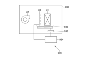
- the nozzle 33 sprays the cooling water supplied from the water supply section 34 toward the exhaust heat exchanger 31.
- the cooling water sprayed from the nozzle 33 is applied to the exhaust heat exchanger 31, thereby cooling the exhaust heat exchanger 31.
- the water supply unit 34 supplies cooling water to the nozzle 33.
- the cooling water is, for example, tap water.
- condensed water condensed in the supply air heat exchanger 21 may be used as the cooling water.
- the cooling water may contain, for example, a rust preventive agent, a fungicide, a cleaning agent, and the like.
- antifreeze may be used as the cooling water.
- the direction in which the cooling water is sprayed from the nozzle may be in a direction opposite to the flow of air.
- the water supply unit 34 includes, for example, a tank that stores cooling water and a pump that sends the cooling water from the tank to the nozzle 33 while pressurizing it.
- the water supply section 34 is connected to the control section 60.
- the control unit 60 controls the water supply unit 34. Water is supplied to the tank storing the cooling water from outside the ventilation device 1, for example from the water supply.
- nozzle 33 and the water supply section 34 are collectively referred to as a water spray section 39.
- cooling water is sprayed from the water spray section 39, but the liquid to be sprayed is not limited to water.
- a liquid other than water may be sprayed from the water spray section 39.
- the ventilation device 1 may include a spraying section that sprays a cooling liquid that is a liquid that cools the exhaust heat exchanger 31 instead of the water spraying section 39 .
- the return air RA that has undergone heat exchange with the refrigerant R2 by the exhaust heat exchanger 31 is blown outdoors of the building BLD by the blower 32 as exhaust EA.
- air A2 second air
- the ventilation system 1 includes, near the exhaust unit 30, a thermometer 31r1 and a thermometer 31r2 that measure the temperature of the refrigerant R1.
- the thermometer 31r1 measures the temperature of the refrigerant R1 flowing through the refrigerant pipe 42 connecting the exhaust unit 30 and the compressor 10.
- the thermometer 31r2 measures the temperature of the refrigerant R1 flowing through the refrigerant pipe 44 connecting the air supply unit 20 and the exhaust unit 30. That is, the thermometer 31r1 measures the temperature of the refrigerant R1 at one refrigerant port of the exhaust heat exchanger 31.
- the thermometer 31r2 measures the temperature of the refrigerant R1 at the other refrigerant port of the exhaust heat exchanger 31.
- thermometer 31r1 and the thermometer 31r2 are connected to the control section 60.
- the control unit 60 obtains the results of measuring the temperature of the refrigerant from each of the thermometer 31r1 and the thermometer 31r2.
- the ventilation device 1 includes a pressure gauge 31p1 and a pressure gauge 31p2 near the exhaust unit 30, which measure the pressure of the refrigerant R1.
- the pressure gauge 31p1 measures the pressure of the refrigerant R1 flowing through the refrigerant pipe 42 connecting the exhaust unit 30 and the compressor 10.
- the pressure gauge 31p2 measures the pressure of the refrigerant R1 flowing through the refrigerant pipe 44 connecting the air supply unit 20 and the exhaust unit 30. That is, the pressure gauge 31p1 measures the pressure of the refrigerant R1 at one refrigerant port of the exhaust heat exchanger 31.
- the pressure gauge 31p2 measures the pressure of the refrigerant R1 at the other refrigerant port of the exhaust heat exchanger 31.
- Each of the pressure gauges 31p1 and 31p2 is connected to the control unit 60.
- the control unit 60 acquires the results of measuring the pressure of the refrigerant from each of the pressure gauges 31p1 and 31p2.
- the ventilation system 1 includes a thermometer 31a1 near the exhaust unit 30 that measures the temperature of the air A2 flowing into the exhaust heat exchanger 31, and a thermometer 31a1 that measures the temperature of the air A2 flowing out from the exhaust heat exchanger 31.
- a thermometer 31a2 is provided.
- the thermometer 31a1 is provided near the inflow side of the exhaust heat exchanger 31.
- the thermometer 31a2 is provided near the outflow side of the exhaust heat exchanger 31.
- thermometer 31a1 and the thermometer 31a2 are connected to the control section 60.
- the control unit 60 obtains the results of measuring the temperature of the air A2 from the thermometer 31a1 and the thermometer 31a2.
- the ventilation device 1 includes a hygrometer 31h near the exhaust unit 30 that measures the humidity of the air A2 flowing into the exhaust heat exchanger 31.
- the hygrometer 31h is provided near the inflow side of the exhaust heat exchanger 31. Note that the hygrometer 31h may measure the humidity of the air A2 flowing out from the exhaust heat exchanger 31.
- the hygrometer 31h is connected to the control unit 60.
- the control unit 60 obtains the result of measuring the humidity of the air A1 from the hygrometer 31h.
- the ventilation device 1 includes a flow meter 33f between the water supply section 34 and the nozzle 33.
- the flow meter 33f measures the flow rate of cooling water supplied from the water supply section 34 to the nozzle 33.
- the flowmeter 33f is, for example, an electromagnetic flowmeter, a vortex flowmeter, an ultrasonic flowmeter, a Coriolis flowmeter, a differential pressure flowmeter, or the like.
- the flow meter 33f is connected to the control section 60.
- the control unit 60 acquires the result of measuring the amount of cooling water sprayed from the nozzle 33 to the exhaust heat exchanger 31 from the flow meter 33f.
- the refrigerant pipe 41 connects between the compressor 10 and the air supply unit 20, more specifically, between the compressor 10 and the air supply heat exchanger 21 provided in the air supply unit 20.
- the refrigerant pipe 42 connects between the compressor 10 and the exhaust unit 30, more specifically, between the compressor 10 and the exhaust heat exchanger 31 provided in the exhaust unit 30.
- the refrigerant pipe 43 connects between the air supply unit 20 and the expansion valve 51, more specifically, between the air supply heat exchanger 21 provided in the air supply unit 20 and the expansion valve 51.
- the refrigerant pipe 44 connects between the exhaust unit 30 and the expansion valve 51, more specifically, between the exhaust heat exchanger 31 included in the exhaust unit 30 and the expansion valve 51.
- the expansion valve 51 reduces the pressure of the refrigerant flowing in from the high pressure side and discharges it.
- the expansion valve 51 reduces the pressure of the inflowing high-pressure side refrigerant R1 and discharges it as refrigerant R2.
- a capillary tube may be used instead of the expansion valve 51.
- the refrigerant circuit 50 is a so-called vapor compression refrigerant circuit.
- the refrigerant circuit 50 includes a compressor 10, a supply air heat exchanger 21, an exhaust heat exchanger 31, a refrigerant pipe 41, a refrigerant pipe 42, a refrigerant pipe 43, a refrigerant pipe 44, and an expansion valve 51. Be prepared.
- the compressor 10, the air supply heat exchanger 21, the exhaust heat exchanger 31, and the expansion valve 51 are connected by refrigerant piping 41, refrigerant piping 42, refrigerant piping 43, and refrigerant piping 44, and the refrigerant is contained inside. flows.
- the compressor 10 supplies compressed refrigerant to the exhaust unit 30.
- the exhaust heat exchanger 31 included in the exhaust unit 30 functions as a condenser by being supplied with compressed refrigerant.
- the air supply heat exchanger 21 included in the air supply unit 20 functions as an evaporator.
- the heat of the return air RA can be recovered and the outside air OA can be cooled.
- the compressor 10 supplies compressed refrigerant to the air supply unit 20.
- the air supply heat exchanger 21 included in the air supply unit 20 functions as a condenser by being supplied with compressed refrigerant.
- the exhaust heat exchanger 31 included in the exhaust unit 30 functions as an evaporator.
- the heat of the return air RA can be recovered and the outside air OA can be heated.
- Control unit 60 The control unit 60 controls the entire ventilation device 1.
- FIG. 4 is a functional block diagram of the control unit 60 included in the ventilation device 1 according to the first embodiment. Note that FIG. 4 also describes components related to the control unit 60.
- the control unit 60 is, for example, a control circuit that includes a processor such as a CPU (Central Processing Unit) and a memory.
- the functions of the control unit 60 are realized by the processor operating according to a program readably stored in the memory.
- a specific example of the control unit 60 is a microcomputer.
- the control unit 60 may be an FPGA (Field Programmable Gate Array) or an ASIC (Application Specific Integrated Circuit).
- the control unit 60 includes a calculation unit 61, a device drive unit 62, and a connection unit 63.
- the calculation unit 61 controls the entire control unit 60. Further, the calculation unit 61 controls the compressor 10 , the blower 22 , the blower 32 , and the water supply unit 34 .
- the equipment drive section 62 outputs signals for controlling the compressor 10, the blower 22, the blower 32, and the water supply section 34.
- connection unit 63 communicates with devices etc. connected to the control unit 60. Connected to the connection part 63 are thermometers 10r1, 10r2, 21a1, 21a2, 21r1, 21r2, 31a1, 31a2, 31r1 and 31r2, pressure gauges 10p1, 10p2, 31p1 and 32p2, and hygrometers 21h and 31h. Ru.
- control unit 60 the devices connected to the control unit 60 are not limited to those described above. Depending on the processing performed by the control unit 60, necessary equipment may be connected as appropriate.
- the ventilation device 1 includes a vapor compression refrigerant circuit 50.
- the ventilation device 1 recovers heat from return air RA and adds the recovered heat to outside air OA to produce supply air SA.
- processing in summer will be explained.
- the temperature of outside air OA is higher than the temperature of return air RA.
- the ventilation system 1 recovers heat from return air RA using a vapor compression refrigerant circuit 50, cools outside air OA, and supplies the cooled air as supply air SA.
- the control unit 60 included in the ventilation device 1 controls the refrigerant circuit 50 so that the temperature of the air supply SA becomes a predetermined set temperature. Specifically, the control unit 60 performs control so that the temperature of the air A1 measured by the thermometer 21a2 becomes the set temperature.
- the ventilation device 1 takes in outside air OA and supplies it indoors as supply air SA, and exhausts return air RA, which is indoor air, as exhaust EA. Therefore, the air volume (supply air volume) of the supply air SA processed by the ventilation device 1 and the air volume (exhaust air volume) of the return air RA are equal.
- the ventilation system 1 needs to discard the heat added to the supply air SA plus the heat generated by the circuit to the exhaust air EA. However, in the ventilation system 1, the intake air amount and the exhaust air amount are controlled to be equal.
- the ventilation device 1 when the temperature of the exhaust gas EA becomes high, the ventilation device 1 according to the first embodiment sprays cooling water on the exhaust heat exchanger 31 to reduce the amount of exhaust gas from the ventilation device 1 using latent heat. Control is performed to lower the temperature of the exhaust EA.
- the ventilation device 1 performs exhaust heat exchange based on at least either the condensation temperature of the exhaust heat exchanger 31 or the discharge pressure discharged from the compressor 10 toward the exhaust heat exchanger 31.
- the water spray section 39 is controlled to spray cooling water onto the container 31.
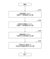
- FIG. 5 is a flowchart showing processing based on the condensing temperature of the exhaust heat exchanger 31 in the ventilation apparatus 1 according to the first embodiment.
- Step S10 When the control unit 60 starts the process, the control unit 60 measures the outlet temperature of the refrigerant R1 in the compressor 10 (step of measuring the outlet temperature of the refrigerant in the compressor 10). The control unit 60 measures the temperature of the refrigerant R1 using the thermometer 10r2. The temperature measured by the thermometer 10r2 is the outlet temperature of the refrigerant in the compressor 10.
- Step S20 the control unit 60 measures the inlet temperature and outlet temperature of the refrigerant R1 in the exhaust heat exchanger 31 (step of measuring the inlet temperature and outlet temperature of the refrigerant in the exhaust heat exchanger 31).
- the control unit 60 measures the temperature of the refrigerant R1 using the thermometer 31r1 and the thermometer 31r2.
- the temperature measured by the thermometer 31r1 is the inlet temperature of the refrigerant in the exhaust heat exchanger 31.
- the temperature measured by the thermometer 31r2 is the outlet temperature of the refrigerant in the exhaust heat exchanger 31.
- Step S30 the control unit 60 calculates the condensation temperature of the refrigerant R1 in the exhaust heat exchanger 31 (step of calculating the condensation temperature of the refrigerant in the exhaust heat exchanger 31).
- the control unit 60 controls the inlet temperature (first temperature) of the refrigerant in the exhaust heat exchanger 31 measured in step S10 and step S20, the outlet temperature (second temperature) of the refrigerant in the exhaust heat exchanger 31, and the compressor 10. Obtain the refrigerant outlet temperature (third temperature) at .
- the control unit 60 calculates the condensation temperature of the refrigerant in the exhaust heat exchanger 31 based on the first temperature, the second temperature, and the third temperature.
- control unit 60 calculates the condensation temperature of the refrigerant in the exhaust heat exchanger 31 based on the measurement results of the thermometer 31r1, the thermometer 31r2, and the thermometer 10r2 measured in step S10 and step S20. .
- control unit 60 calculates the condensation temperature of the refrigerant in the exhaust heat exchanger 31 using the first temperature, the second temperature, and the third temperature.
- control unit 60 includes a table showing the relationship between the first temperature, the second temperature, the third temperature, and the condensation temperature, and uses the table to calculate the relationship between the measured first temperature, second temperature, and third temperature.
- the condensation temperature may be calculated.
- the control unit 60 may calculate the condensation temperature using any one of the first temperature, the second temperature, and the third temperature, or may calculate the condensation temperature using any one of the first temperature, the second temperature, and the third temperature.
- the control unit 60 calculates the condensation temperature of the refrigerant in the exhaust heat exchanger 31 using at least one of the first temperature, the second temperature, and the third temperature.
- control unit 60 may measure only the temperature used to calculate the condensation temperature of the refrigerant in the exhaust heat exchanger 31 in step S30 in step S10 and step S20.
- Step S40 the control unit 60 determines whether the condensation temperature of the refrigerant in the exhaust heat exchanger 31 calculated in step S30 is equal to or higher than the target temperature (step of determining whether the condensation temperature is equal to or higher than the target temperature).
- the target temperature is a predetermined temperature or a preset temperature.
- the target temperature is determined, for example, from the allowable temperature in the refrigerant circuit 50, the allowable temperature of the exhaust gas EA, and the like.
- step S30 If the condensation temperature calculated in step S30 is equal to or higher than the target temperature (YES in step S40), the control unit 60 advances the process to step S50. If the condensation temperature calculated in step S30 is less than the target temperature (NO in step S40), the control unit 60 advances the process to step S60.
- step S40 it is determined whether the condensation temperature of the refrigerant in the exhaust heat exchanger 31 calculated in step S30 is equal to or higher than the target temperature, but it is determined whether the condensation temperature is higher than the target temperature. It's okay.
- control unit 60 controls the water spray unit 39 to spray cooling water to the exhaust heat exchanger 31 based on the condensation temperature.
- Step S50 If the condensation temperature calculated in step S30 is equal to or higher than the target temperature (YES in step S40), the control unit 60 controls the water spray unit 39 to spray cooling water from the nozzle 33 to the exhaust heat exchanger 31. (a step of spraying cooling water from the nozzle 33 to the exhaust heat exchanger 31).
- the control unit 60 sprays a large amount of cooling water from the nozzle 33 when the difference between the condensation temperature and the target temperature is large.
- the water spray section 39 is controlled as follows.
- step S50 the control unit 60 advances the process to step S70.
- Step S60 If the condensation temperature calculated in step S30 is less than the target temperature (NO in step S40), the control unit 60 stops spraying the cooling water from the nozzle 33 (stops spraying the cooling water from the nozzle 33). process). Note that if the cooling water is not being sprayed from the nozzle 33, the spraying of the cooling water continues to be stopped.
- step S60 After completing step S60, the control unit 60 advances the process to step S70.
- Step S70 the control unit 60 determines whether to end the process (step of determining whether to end the process).
- step S70 If the process is to be ended (YES in step S70), the control unit 60 advances the process to step S80. If the process does not end (NO in step S70), the control unit 60 returns to step S10 and repeats the process.
- Step S80 The control unit 60 stops the process (step of stopping the process).
- the control unit 60 performs post-processing such as stopping the spraying of water if cooling water is being sprayed from the nozzle 33, for example.
- FIG. 6 is a flowchart showing processing based on the discharge pressure discharged by the compressor 10 toward the exhaust heat exchanger 31 in the ventilation apparatus 1 according to the first embodiment.
- Step S15 When the control unit 60 starts the process, the control unit 60 measures the outlet pressure of the refrigerant R1 in the compressor 10 (a step of measuring the outlet pressure of the refrigerant in the compressor 10). The control unit 60 measures the pressure of the refrigerant R1 using the pressure gauge 10p2. The pressure measured by the pressure gauge 10p2 is the outlet pressure of the refrigerant in the compressor 10.
- Step S25 the control unit 60 measures the inlet pressure and outlet pressure of the refrigerant R1 in the exhaust heat exchanger 31 (step of measuring the inlet pressure and outlet pressure of the refrigerant in the exhaust heat exchanger 31).
- the control unit 60 measures the pressure of the refrigerant R1 using the pressure gauge 31p1 and the pressure gauge 31p2.
- the pressure measured by the pressure gauge 31p1 is the refrigerant inlet pressure in the exhaust heat exchanger 31.
- the pressure measured by the pressure gauge 31p2 is the outlet pressure of the refrigerant in the exhaust heat exchanger 31.
- Step S35 the control unit 60 calculates the discharge pressure of the refrigerant R1 discharged from the compressor 10 to the exhaust heat exchanger 31 (calculates the discharge pressure of the refrigerant R1 discharged from the compressor 10 to the exhaust heat exchanger 31 process).
- the control unit 60 controls the inlet pressure (first pressure) of the refrigerant in the exhaust heat exchanger 31 measured in step S15 and step S25, the outlet pressure (second pressure) of the refrigerant in the exhaust heat exchanger 31, and the compressor 10. Obtain the refrigerant outlet pressure (third pressure) at .
- the control unit 60 calculates the discharge pressure of the refrigerant R1 to be discharged from the compressor 10 to the exhaust heat exchanger 31 based on the first pressure, the second pressure, and the third pressure. In other words, the control unit 60 controls the refrigerant to be discharged from the compressor 10 to the exhaust heat exchanger 31 based on the measurement results of the pressure gauge 31p1, pressure gauge 31p2, and pressure gauge 10p2 measured in step S15 and step S25. Calculate the discharge pressure of R1.
- control unit 60 calculates the discharge pressure of the refrigerant R1 discharged from the compressor 10 to the exhaust heat exchanger 31 using the first pressure, the second pressure, and the third pressure.
- control unit 60 includes a table showing the relationship between the first pressure, the second pressure, the third pressure, and the discharge pressure, and uses the table to calculate the relationship between the measured first pressure, second pressure, and third pressure.
- the discharge pressure may be calculated.
- the control unit 60 may calculate the discharge pressure using any one of the first pressure, the second pressure, and the third pressure, or may calculate the discharge pressure using any one of the first pressure, the second pressure, and the third pressure.
- one pressure may be selected and the discharge pressure may be calculated based on the selected pressure. That is, the control unit 60 calculates the discharge pressure of the refrigerant R1 discharged from the compressor 10 to the exhaust heat exchanger 31 using at least one of the first pressure, the second pressure, and the third pressure.
- step S35 the control unit 60 measures only the pressure used to calculate the discharge pressure of the refrigerant R1 discharged from the compressor 10 to the exhaust heat exchanger 31 in steps S15 and S25. It's okay.
- Step S45 the control unit 60 determines whether the discharge pressure of the refrigerant R1 discharged from the compressor 10 to the exhaust heat exchanger 31 calculated in step S35 is equal to or higher than the target pressure (whether the discharge pressure is equal to or higher than the target pressure process of determining whether
- the target pressure is a predetermined pressure or a preset pressure.
- the target pressure is determined, for example, from the allowable pressure in the refrigerant circuit 50, the allowable temperature of the exhaust gas EA, and the like.
- step S35 If the discharge pressure calculated in step S35 is equal to or higher than the target pressure (YES in step S45), the control unit 60 advances the process to step S50. If the discharge pressure calculated in step S30 is less than the target pressure (NO in step S45), the control unit 60 advances the process to step S60.
- step S45 it is determined whether the discharge pressure of the refrigerant in the exhaust heat exchanger 31 calculated in step S35 is equal to or higher than the target pressure, but it is determined whether the discharge pressure is higher than the target pressure. It's okay.
- control unit 60 controls the water spray unit 39 to spray cooling water to the exhaust heat exchanger 31 based on the discharge pressure.
- step S50 step S60, step S70, and step S80, the details of the processing are the same as those described above, so the explanation will be omitted.
- the control unit 60 determines, for example, based on the difference between the discharge pressure and the target pressure calculated in step S35, that if the difference between the discharge pressure and the target pressure is large, the control unit 60 releases a large amount from the nozzle 33.
- the water spray section 39 is controlled to spray cooling water of .
- the ventilation system 1 lowers the condensing temperature by using the latent heat of the cooling water by spraying water on the exhaust heat exchanger 31 that serves as a condenser, and the refrigerant reaches a high temperature or high pressure. You can prevent it from happening. By suppressing the refrigerant from becoming high temperature or high pressure, the ventilation device 1 can provide high cooling capacity.
- the ventilation device 1 can efficiently exhaust heat from the exhaust heat exchanger 31, which is an exhaust heat exchanger, by spraying water on the exhaust heat exchanger 31, which is a condenser.
- the ventilation device 1 can be operated for a long period of time by controlling the condensing temperature and the discharge pressure so that they do not become high.
- the air supply route P1 is an example of the first route
- the exhaust route P2 is an example of the second route
- the supply air heat exchanger 21 is an example of the first heat exchanger
- the exhaust heat exchanger 31 is an example of the second heat exchanger.
- This is an example of a container.
- the thermometer 31r1 or the thermometer 31r2 is an example of the first temperature detector
- the thermometer 10r2 is an example of the second temperature detector
- the pressure gauge 31p1 or the pressure gauge 31p2 is an example of the first pressure detector
- the pressure gauge 10p2 is an example of the second pressure detector.
- a ventilation device 2 according to a second embodiment will be described.
- the ventilation device 1 sprays cooling water onto the exhaust heat exchanger 31 from the nozzle 33, but the ventilation device 2 sprays cooling water onto the exhaust heat exchanger 31 from the nozzle to the cooling unit 35 provided upstream of the exhaust heat exchanger 31 in the exhaust path P2. Cooling water is sprayed from 33.
- FIG. 7 is a diagram showing a schematic configuration of a ventilation device 2 according to the second embodiment.
- the ventilation device 2 according to the second embodiment includes an exhaust unit 130 in place of the exhaust unit 30 of the ventilation device 1 according to the first embodiment.
- the description of the configuration common to the ventilation device 1 will be omitted as the above description will be referred to.
- the exhaust unit 130 included in the ventilation device 2 the points that are different from the exhaust unit 30 will be explained in particular.
- the exhaust unit 130 takes in return air RA from inside the building BLD, performs heat exchange between the taken in return air RA and refrigerant R1, and exhausts the return air RA after the heat exchange to the outside of the building BLD. Exhaust.
- the exhaust unit 130 further includes a cooling section 35 in addition to the configuration of the exhaust unit 30.
- the cooling unit 35 holds cooling water and cools the air A2 passing therethrough using the heat of vaporization of the cooling water.
- the cooling unit 35 has a configuration through which air A2 can pass. Further, the cooling unit 35 is formed of a water absorbing material that absorbs and retains water inside and discharges the retained water from the inside to the outside. The cooling unit 35 cools the passing air A2 using heat of vaporization when water is discharged from the water absorbing material to the outside.
- the water absorbing material is, for example, silica, polymer adsorbent, etc.
- the water-absorbing material is preferably a material that swells when it absorbs water and deflates when it drains water.
- the cooling unit 35 uses an absorbent material that absorbs and retains liquid inside and discharges the retained liquid from the inside to the outside. It may be made of material.
- the nozzle 33 sprays cooling water supplied from the water supply section 34 toward the cooling section 35 .
- the cooling water sprayed from the nozzle 33 is applied to the cooling unit 35 to cool the air A2 passing through the cooling unit 35.
- the ventilation device 2 according to the second embodiment is similar to the ventilation device 1 according to the first embodiment, in which the condensation temperature of the exhaust heat exchanger 31 or the discharge discharged by the compressor 10 toward the exhaust heat exchanger 31 is The nozzle 33 sprays cooling water based on at least one of the pressures. However, the objects to which the nozzle 33 sprays cooling water are different. That is, the nozzle 33 of the ventilation device 2 sprays cooling water not to the exhaust heat exchanger 31 like the ventilation device 1, but to the cooling unit 35.
- FIG. 8 is a flowchart showing processing based on the condensing temperature of the exhaust heat exchanger 31 in the ventilation device 2 according to the second embodiment.
- the control unit 60 of the ventilation device 2 executes step S150 in place of step S50 (see FIG. 5) executed by the control unit 60 of the ventilation device 1.
- Step S150 If the condensation temperature calculated in step S30 is equal to or higher than the target temperature (YES in step S40), the control unit 60 controls the water spray unit 39 to spray cooling water from the nozzle 33 to the cooling unit 35 (nozzle 33 to the cooling section 35).
- the control unit 60 sprays a large amount of cooling water from the nozzle 33 when the difference between the condensation temperature and the target temperature is large.
- the water spray section 39 is controlled as follows.
- FIG. 9 is a flowchart showing processing based on the discharge pressure discharged by the compressor 10 toward the exhaust heat exchanger 31 in the ventilation device 2 according to the second embodiment.
- the control unit 60 of the ventilation device 2 executes step S150 in place of step S50 (see FIG. 6) executed by the control unit 60 of the ventilation device 1.
- Step S150 If the discharge pressure calculated in step S35 is equal to or higher than the target pressure (YES in step S45), the control unit 60 controls the water spray unit 39 to spray cooling water from the nozzle 33 to the cooling unit 35 (nozzle 33 to the cooling section 35).
- the control unit 60 sprays a large amount of cooling water from the nozzle 33 when the difference between the discharge pressure and the target pressure is large.
- the water spray section 39 is controlled as follows. By spraying water to the cooling unit 35, the ventilation device 2 can efficiently exhaust heat from the exhaust heat exchanger 31, which is an exhaust heat exchanger.
- the ventilation device 1 according to the first embodiment and the ventilation device 2 according to the second embodiment may be combined to spray cooling water onto both the exhaust heat exchanger 31 and the cooling unit 35.
- the ventilation device 2 according to the second embodiment by spraying more cooling water from the nozzle 33, a part of the cooling water sprayed to the cooling unit 35 is used for exhaust gas through the cooling unit 35. It may also be applied to the heat exchanger 31.
- cooling unit 35 is not limited to use in a ventilation system, but may also be used, for example, to cool air supplied to an outdoor heat exchanger or the like in an air conditioner.
- FIG. 10 is a diagram showing an outline of the exhaust heat exchanger 131 used in the heat exchanger according to this embodiment.
- FIG. 10 is a partially cutaway perspective view of the exhaust heat exchanger 131.
- the exhaust heat exchanger 131 includes a plurality of plate-shaped fins 131f and a plurality of pipes 131p through which the refrigerant flows through the fins 131f.
- the plurality of fins 131f are provided at intervals.
- the plurality of fins 131f are connected to the piping 131p. Air flows between the plurality of fins 131f.
- a refrigerant flows through the plurality of pipes 131p.
- a liquid holding portion 131w is formed on the surfaces of the fins 131f and the pipe 131p, and is made of a water absorbing material that can absorb and hold water inside and discharge the held water from the inside to the outside.
- the same material as the water absorbing material of the cooling section 35 is used for the water absorbing material.
- the liquid holding unit 131w may be formed of an absorbent material that holds liquid inside.
- the sprayed cooling water is held by the water absorbing material of the liquid holding section 131w.
- the heat of vaporization cools the fins 131f in which the liquid retaining portion 131w is formed and the piping 131p.
- the refrigerant flowing through the pipe 131p can be further cooled not only by air but also by vaporization heat (latent heat).
- the cooling water sprayed from the nozzle 33 can be held in the fins 131f and the pipe 131p, the refrigerant can be cooled more stably.
- exhaust heat exchanger 131 is not limited to the exhaust heat exchanger of a ventilation system, but may also be used, for example, as a supply air heat exchanger, an outdoor heat exchanger in an air conditioner, etc.
- the piping 131p is an example of internal piping.
- the exhaust heat exchanger 131 can be used as an exhaust heat exchanger in each of the embodiments of the present disclosure.
- the ventilation system 3 further includes a second exhaust heat exchanger 36 upstream of the exhaust heat exchanger 31 in the ventilation system 1 .
- FIG. 11 is a diagram showing a schematic configuration of a ventilation device 3 according to the third embodiment.
- the ventilation device 3 according to the third embodiment includes an exhaust unit 230 in place of the exhaust unit 30 of the ventilation device 1 according to the first embodiment. Further, the ventilation device 3 according to the third embodiment includes a refrigerant circuit 55 in place of the refrigerant circuit 50 of the ventilation device 1 according to the first embodiment.
- the description of the configuration common to the ventilation device 1 will be omitted as the above description will be referred to.
- the exhaust unit 230 and the refrigerant circuit 55 included in the ventilation device 3 the points that are different from the exhaust unit 30 and the refrigerant circuit 50, respectively, will be described in particular.
- the exhaust unit 230 takes in return air RA from inside the building BLD, performs heat exchange between the taken in return air RA and refrigerant R1, and exhausts the return air RA after the heat exchange to the outside of the building BLD. Exhaust.
- the exhaust unit 230 includes a second exhaust heat exchanger 36 upstream of the exhaust heat exchanger 31 in the exhaust path P2. The second exhaust heat exchanger 36 is provided upstream of the nozzle 33 in the exhaust path P2.
- the second exhaust heat exchanger 36 exchanges heat between the air A2 blown from the blower 32 and the refrigerant R1.
- the air A2 that has passed through the second exhaust heat exchanger 36 further exchanges heat with the refrigerant R1 in the downstream exhaust heat exchanger 31.
- the second exhaust heat exchanger 36 is connected to the expansion valve 51 via the refrigerant pipe 44. Further, the second exhaust heat exchanger 36 is connected to the exhaust heat exchanger 31 via a refrigerant pipe 45.
- the refrigerant circuit 55 is a so-called vapor compression refrigerant circuit.
- the refrigerant circuit 55 includes a compressor 10, a supply air heat exchanger 21, an exhaust heat exchanger 31, a second exhaust heat exchanger 36, a refrigerant pipe 41, a refrigerant pipe 42, a refrigerant pipe 43, and a refrigerant pipe. 44, a refrigerant pipe 45, and an expansion valve 51.
- the refrigerant circuit 55 includes a compressor 10, a supply air heat exchanger 21, an exhaust heat exchanger 31, a second exhaust heat exchanger 36, and an expansion valve 51 that are connected to a refrigerant pipe 41, a refrigerant pipe 42, a refrigerant pipe 43, and a refrigerant They are connected by a pipe 44 and a refrigerant pipe 45, and a refrigerant flows inside.
- the ventilation device 3 can more efficiently exchange heat between the air A2 and the refrigerant R1.
- the ventilation device 3 can efficiently exhaust heat from the exhaust heat exchanger 31 and the second exhaust heat exchanger 36, which are exhaust heat exchangers.
- the ventilation device 3 includes one second exhaust heat exchanger 36, it may include two or more second exhaust heat exchangers 36.
- the second exhaust heat exchanger 36 is an example of the third heat exchanger.
- a ventilation device 4 according to a fourth embodiment will be explained.
- the ventilation system 4 further includes a second exhaust heat exchanger 36 upstream of the exhaust heat exchanger 31 in the ventilation system 2 .
- the nozzle 33 sprays cooling water to the cooling unit 35 instead of the nozzle 33 spraying cooling water to the exhaust heat exchanger 31 in the ventilation device 3.
- FIG. 12 is a diagram showing a schematic configuration of a ventilation device 4 according to the fourth embodiment.
- the ventilation device 4 according to the fourth embodiment includes an exhaust unit 330 in place of the exhaust unit 230 of the ventilation device 3 according to the third embodiment.
- the description of the configuration common to the ventilation device 3 will be omitted as the above description will be referred to.
- the exhaust unit 330 included in the ventilation device 3 the points that are different from the exhaust unit 230 will be explained in particular.
- the exhaust unit 330 takes in return air RA from inside the building BLD, performs heat exchange between the taken in return air RA and refrigerant R1, and exhausts the return air RA after the heat exchange to the outside of the building BLD. Exhaust.
- the exhaust unit 330 includes a cooling unit 35 between the exhaust heat exchanger 31 and the second exhaust heat exchanger 36 in the exhaust path P2, more specifically, between the nozzle 33 and the exhaust heat exchanger 31. Be prepared.
- the nozzle 33 of the ventilation device 4 sprays cooling water not to the exhaust heat exchanger 31 but to the cooling unit 35.
- the ventilation device 4 can more efficiently exchange heat between the air A2 and the refrigerant R1.
- the ventilation device 4 can efficiently exhaust heat from the exhaust heat exchanger 31 and the second exhaust heat exchanger 36, which are exhaust heat exchangers.
- the ventilation device 4 includes one second exhaust heat exchanger 36, it may include two or more second exhaust heat exchangers 36.
- the ventilation device 5 further includes a second nozzle 33a and a third exhaust heat exchanger 37 on the downstream side of the exhaust heat exchanger 31 in the ventilation device 1.
- FIG. 13 is a diagram showing a schematic configuration of a ventilation device 5 according to the fifth embodiment.
- the ventilation device 5 according to the fifth embodiment includes an exhaust unit 430 in place of the exhaust unit 30 of the ventilation device 1 according to the first embodiment.
- the ventilation device 3 according to the third embodiment includes a refrigerant circuit 56 in place of the refrigerant circuit 50 of the ventilation device 1 according to the first embodiment.
- the description of the configuration common to the ventilation device 1 will be omitted as the above description will be referred to.
- the exhaust unit 430 and the refrigerant circuit 56 included in the ventilation device 5 the points that are different from the exhaust unit 30 and the refrigerant circuit 50, respectively, will be explained.
- the exhaust unit 430 takes in return air RA from inside the building BLD, performs heat exchange between the taken in return air RA and refrigerant R1, and exhausts the return air RA after the heat exchange to the outside of the building BLD.
- the exhaust unit 230 includes a third exhaust heat exchanger 37 downstream of the exhaust heat exchanger 31 in the exhaust path P2. Further, a second nozzle 33a is provided between the exhaust heat exchanger 31 and the third exhaust heat exchanger 37.
- the third exhaust heat exchanger 37 performs heat exchange between the air A2 that has passed through the exhaust heat exchanger 31 and the refrigerant R1. Moreover, the third exhaust heat exchanger 37 is sprayed with cooling water from the second nozzle 33a.
- the third exhaust heat exchanger 37 is connected to the exhaust heat exchanger 31 via a refrigerant pipe 46. Further, the third exhaust heat exchanger 37 is connected to the compressor 10 via a refrigerant pipe 42.
- the second nozzle 33a sprays the cooling water supplied from the water supply section 34a toward the third exhaust heat exchanger 37.
- the cooling water sprayed from the second nozzle 33a cools the third exhaust heat exchanger 37 by being applied to the third exhaust heat exchanger 37.
- the water supply section 34a supplies cooling water to the second nozzle 33a.
- the water supply unit 34a includes, for example, a tank that stores cooling water and a pump that sends the cooling water from the tank to the second nozzle 33a while pressurizing it.
- the water supply section 34a is connected to the control section 60.
- the control section 60 controls the water supply section 34a.
- the ventilation device 5 includes a flow meter 33af between the water supply section 34a and the second nozzle 33a. The flow meter 33af measures the flow rate of cooling water supplied from the water supply section 34a to the second nozzle 33a.
- the flowmeter 33af is, for example, an electromagnetic flowmeter, a vortex flowmeter, an ultrasonic flowmeter, a Coriolis flowmeter, a differential pressure flowmeter, or the like.
- Flow meter 33af is connected to control section 60.
- the control unit 60 acquires the result of measuring the amount of cooling water sprayed from the second nozzle 33a to the third exhaust heat exchanger 37 from the flow meter 33af.
- the control section 60 performs the same control as the water spray section 39 on the water spray section 39a.
- the refrigerant circuit 56 is a so-called vapor compression refrigerant circuit.
- the refrigerant circuit 56 includes a compressor 10, a supply air heat exchanger 21, an exhaust heat exchanger 31, a third exhaust heat exchanger 37, refrigerant piping 41, refrigerant piping 42, refrigerant piping 43, and refrigerant piping. 44, a refrigerant pipe 46, and an expansion valve 51.
- the refrigerant circuit 56 includes a compressor 10, a supply air heat exchanger 21, an exhaust heat exchanger 31, a third exhaust heat exchanger 37, and an expansion valve 51 that are connected to a refrigerant pipe 41, a refrigerant pipe 42, a refrigerant pipe 43, and a refrigerant They are connected by a pipe 44 and a refrigerant pipe 46, and a refrigerant flows inside.
- the ventilation device 5 can more efficiently exchange heat with the refrigerant R1. Further, the ventilation device 5 can cool the refrigerant R1 more efficiently. The ventilation device 5 can efficiently exhaust heat from the exhaust heat exchanger 31 and the third exhaust heat exchanger 37, which are exhaust heat exchangers.
- the ventilation device 5 includes one set of the water spray section 39a and the third exhaust heat exchanger 37, it may also include two or more sets of the water spray section 39a and the third exhaust heat exchanger 37. good.
- the ventilation system 4 further includes a third exhaust heat exchanger 37 downstream of the exhaust heat exchanger 31 in the ventilation system 2 .
- the nozzle 33 sprays cooling water to the cooling unit 38 instead of the nozzle 33 spraying the cooling water to the exhaust heat exchanger 31 in the ventilation device 5.
- the second nozzle 33a sprays cooling water to the cooling unit 38 instead of the second nozzle 33a spraying the cooling water to the third exhaust heat exchanger 37. .
- FIG. 14 is a diagram showing a schematic configuration of a ventilation device 6 according to the sixth embodiment.
- the ventilation device 6 according to the sixth embodiment includes an exhaust unit 530 in place of the exhaust unit 430 of the ventilation device 5 according to the fifth embodiment.
- the description of the configuration common to the ventilation device 5 will be omitted as the above description will be referred to.
- the exhaust unit 530 included in the ventilation device 5 the points that are different from the exhaust unit 430 will be explained in particular.
- the exhaust unit 530 takes in return air RA from inside the building BLD, performs heat exchange between the taken in return air RA and refrigerant R1, and exhausts the return air RA after the heat exchange to the outside of the building BLD. Exhaust.
- the exhaust unit 530 includes a cooling section 35 upstream of the exhaust heat exchanger 31 and a cooling section 38 upstream of the third exhaust heat exchanger 37 in the exhaust path P2 with respect to the exhaust unit 430.
- the cooling unit 38 has a similar configuration to the cooling unit 35.
- the nozzle 33 of the ventilation device 6 sprays cooling water not to the exhaust heat exchanger 31 but to the cooling unit 35. Further, the second nozzle 33a of the ventilation device 6 sprays cooling water not to the third exhaust heat exchanger 37 but to the cooling unit 38.
- the ventilation device 6 can more efficiently exchange heat with the refrigerant R1. Further, the ventilation device 6 can cool the refrigerant R1 more efficiently. The ventilation device 6 can efficiently exhaust heat from the exhaust heat exchanger 31 and the third exhaust heat exchanger 37, which are exhaust heat exchangers.
- the ventilation device 5 includes one set of water spray section 39a, cooling section 38, and third exhaust heat exchanger 37; however, two or more sets of water spray section 39a, cooling section 38, and third exhaust heat exchanger 37 A container 37 may be provided.
- the cooling unit 38 is an example of a second cooling unit
- the third exhaust heat exchanger 37 is an example of a fourth heat exchanger
- the water spray unit 39a is an example of a second water spray unit
- water is sprayed from the second nozzle 33a.
- the second cooling water is an example of the second cooling water.
- a ventilation device according to a seventh embodiment will be described.
- the ventilation device executes a process of calculating the amount of cooling water to be sprayed in step S50 or step S150 described above.
- the ventilation device learns the relationship between the temperature of the refrigerant flowing through the refrigerant circuit, the flow rate of the cooling water, and the condensing temperature, creates a predictive model, and uses the cooling water based on the predictive model. Calculate the flow rate. Further, the ventilation device according to the seventh embodiment learns the relationship between the pressure of the refrigerant flowing through the refrigerant circuit, the flow rate of the cooling water, and the discharge pressure, creates a predictive model, and based on the predictive model, Calculate the flow rate of cooling water.
- FIG. 15 is a flowchart showing processing based on the condensing temperature of the exhaust heat exchanger 31 in the ventilation system according to the seventh embodiment.
- Step S210 When the process starts, the control unit 60 sets the first temperature of the refrigerant R1 supplied to the exhaust heat exchanger 31, the second temperature of the refrigerant R1 discharged from the exhaust heat exchanger 31, and At least one of the third temperatures of the refrigerant R1 discharged from the compressor 10 to the second heat exchanger is acquired.
- the control unit 60 sets at least one of the acquired first temperature, second temperature, and third temperature as first learning data (a step of acquiring learning data regarding refrigerant temperature).
- Step S220 Next, the control unit 60 obtains the flow rate of the cooling water sprayed by the water spray unit 39 under a plurality of operating conditions.
- the control unit 60 sets the acquired flow rate of the cooling water as second learning data (a step of acquiring learning data regarding the flow rate of the cooling water).
- Step S230 the control unit 60 learns a prediction model (first prediction model) that predicts how much the condensation temperature in the exhaust heat exchanger 31 will decrease based on the first learning data and the second learning data. Specifically, the control unit 60 predicts how much the condensation temperature in the exhaust heat exchanger 31 will decrease based on at least one of the first temperature, the second temperature, and the third temperature and the flow rate of the cooling water. Create a predictive model for the condensation temperature (step of learning the predictive model for the condensation temperature).
- Step S240 the control unit 60 calculates the flow rate of the cooling water to be sprayed from the water spray unit based on the prediction model learned in step S240. Specifically, the control unit 60 calculates the flow rate of the cooling water sprayed from the water spray unit based on at least one of the first temperature, second temperature, and third temperature used for learning and the condensation temperature. (Process of calculating the flow rate of cooling water using a prediction model).
- FIG. 16 is a flowchart showing processing based on the discharge pressure discharged by the compressor 10 toward the exhaust heat exchanger 31 in the ventilation system according to the seventh embodiment.
- Step S310 When the process is started, the control unit 60 sets the first pressure of the refrigerant R1 supplied to the exhaust heat exchanger 31, the second pressure of the refrigerant R1 discharged from the exhaust heat exchanger 31, and At least one of the third pressures of the refrigerant R1 discharged from the compressor 10 to the second heat exchanger is acquired.
- the control unit 60 sets at least one of the acquired first pressure, second pressure, and third pressure as third learning data (a step of acquiring learning data regarding refrigerant pressure).
- Step S320 Next, the control unit 60 obtains the flow rate of the cooling water sprayed by the water spray unit 39 under a plurality of operating conditions.
- the control unit 60 sets the acquired flow rate of the cooling water as fourth learning data (a step of acquiring learning data regarding the flow rate of the cooling water).
- Step S330 the control unit 60 uses a predictive model (a predictive model) that predicts how much the discharge pressure discharged from the compressor 10 toward the exhaust heat exchanger 31 will decrease based on the third learning data and the fourth learning data. 2 prediction model) (step of learning a prediction model regarding discharge pressure). Specifically, the control unit 60 determines the amount of discharge that the compressor 10 discharges toward the exhaust heat exchanger 31 based on at least one of the first pressure, the second pressure, and the third pressure and the flow rate of the cooling water. Create a predictive model to predict how much pressure will drop.
- a predictive model a predictive model
- Step S340 the control unit 60 calculates the flow rate of the cooling water to be sprayed from the water spray unit based on the prediction model learned in step S340. Specifically, the control unit 60 calculates the flow rate of cooling water sprayed from the water spray unit from at least one of the first pressure, second pressure, and third pressure used for learning and the discharge pressure ( (process of calculating the flow rate of cooling water using a prediction model).
- the amount of water to be sprayed can be optimized by calculating the amount of cooling water to be sprayed using a prediction model.
- FIG. 17 is a side view illustrating how the ventilation device 1 according to the present embodiment is used.
- the ventilation device 8 supplies outside air OA, which is the outdoor air of the building BLD, to the indoor space of the building BLD. Further, the ventilation device 8 exhausts the indoor air of the building BLD to the outside of the building BLD as exhaust EA.
- the ventilation device 8 ventilates the indoor air of the building BLD by supplying and exhausting air.
- the ventilation device 8 includes a compressor 510, an air supply unit 520, and an exhaust unit 530.
- the ventilation system 8 also includes a compressor 510, an air supply heat exchanger 521 of an air supply unit 520 (described later), an exhaust heat exchanger 531 of an exhaust unit 530 (described later), an expansion valve (not shown), and refrigerant piping. 540, and a refrigerant circuit 550.
- the ventilation device 8 includes measuring instruments such as a thermometer that measures the temperature of the refrigerant and a pressure gauge that measures the pressure of the refrigerant, and a control unit that performs control.
- measuring instruments such as a thermometer that measures the temperature of the refrigerant and a pressure gauge that measures the pressure of the refrigerant
- a control unit that performs control. The explanation will be omitted as the reference will be made to the following.
- Compressor 510 compresses refrigerant flowing through refrigerant circuit 550. For example, in summer, when the indoor temperature of the building BLD is lower than the outdoor temperature due to an air conditioner or the like, the compressor 510 supplies compressed refrigerant to the exhaust unit 530. Further, for example, in winter, when the indoor temperature of the building BLD is higher than the outdoor temperature due to heating equipment or the like, the compressor 510 supplies compressed refrigerant to the air supply unit 520.
- Air supply unit 520 takes in outside air OA from outside of the building BLD, performs heat exchange between the taken outside air OA and the refrigerant, and supplies the outside air OA after the heat exchange to the inside of the building BLD as air supply SA. do.
- the air supply unit 520 includes a heat exchanger 521 for air supply.
- the air supply heat exchanger 521 exchanges heat between the outside air OA and the refrigerant.
- the air supply heat exchanger 521 includes a plurality of plate-shaped fins and piping through which the refrigerant flows through the fins.
- the supply air heat exchanger 521 is connected to the compressor 510 via a refrigerant pipe 540, and is also connected to an exhaust heat exchanger 531 included in the exhaust unit 530 via the refrigerant pipe 540, thereby transferring heat for supply air.
- Refrigerant flows through the pipes of the exchanger 521.
- the outside air OA that has undergone heat exchange with the refrigerant by the air supply heat exchanger 521 is blown as air supply SA from the underfloor UF of the building BLD to the room RM1 by the blower BLW.
- the exhaust unit 530 takes in the return air RA from the room RM1 of the building BLD through the attic AT, exchanges heat between the taken in return air RA and the refrigerant, and exhausts the return air RA after the heat exchange. Exhaust to the outside of the building BLD.
- FIG. 18 is a diagram schematically showing an exhaust unit 530 of the ventilation device 8 according to the eighth embodiment.
- the exhaust unit 530 is provided on the rooftop RF of the building BLD.
- the exhaust unit 530 includes an exhaust heat exchanger 531, a blower 532, and a nozzle 533.
- the exhaust heat exchanger 531 exchanges heat between the return air RA and the refrigerant.
- the exhaust heat exchanger 531 includes piping 531p and a filler 531a.
- the exhaust heat exchanger 531 is connected to the compressor 10 via the refrigerant pipe 540, and is also connected to the air supply heat exchanger 521 included in the air supply unit 520 via the refrigerant pipe 540, thereby transferring exhaust heat.
- Refrigerant flows through the pipes of the exchanger 531.
- heat exchange is performed between the return air RA and the refrigerant flowing through the pipe 531p of the exhaust heat exchanger 531.
- the blower 532 blows return air RA to the exhaust heat exchanger 531.
- the blower 532 is, for example, a centrifugal blower or an axial blower.
- the return air RA heat-exchanged by the exhaust heat exchanger 531 is discharged outdoors as exhaust EA.
- the nozzle 533 sprays the cooling water supplied from the water supply section 534 toward the exhaust heat exchanger 531.
- the cooling water sprayed from the nozzle 533 is applied to the exhaust heat exchanger 531, thereby cooling the exhaust heat exchanger 531.
- the water supply section 534 supplies cooling water to the nozzle 533.
- the water supply unit 534 includes, for example, a tank 534a that stores cooling water, a pump that sends the cooling water from the tank to the nozzle 33 under pressure, and a pipe 534b that sends the cooling water from the pump to the nozzle 533.
- the return air RA that has undergone heat exchange with the exhaust heat exchanger 531 is blown outside the building BLD as exhaust EA.
- the cooling water WTR is caused to flow opposite to the flow of the air AIR. That is, the exhaust unit 530 includes a nozzle 533 on the downstream side of the flow of air AIR of the exhaust heat exchanger 531.
- the refrigerant pipe 540 connects the compressor 510, the air supply heat exchanger 521, the exhaust heat exchanger 531, and an expansion valve (not shown). A refrigerant flows through the refrigerant pipe 540 .
- the refrigerant circuit 550 is a so-called vapor compression refrigerant circuit.
- the refrigerant circuit 550 includes a compressor 510, an air supply heat exchanger 521, an exhaust heat exchanger 531, a refrigerant pipe 540, and an expansion valve (not shown).
- the compressor 510, the air supply heat exchanger 521, the exhaust heat exchanger 531, and the expansion valve are connected by a refrigerant pipe 540, and refrigerant flows inside.
- the operation of the refrigerant circuit 550 will be explained.
- the compressor 510 supplies compressed refrigerant to the exhaust unit 530.
- the exhaust heat exchanger 531 included in the exhaust unit 530 functions as a condenser by being supplied with compressed refrigerant.
- the air supply heat exchanger 521 included in the air supply unit 520 functions as an evaporator.
- the heat of the return air RA can be recovered and the outside air OA can be cooled.
- the compressor 510 supplies compressed refrigerant to the air supply unit 520.
- the air supply heat exchanger 521 included in the air supply unit 520 functions as a condenser by being supplied with compressed refrigerant.
- the exhaust heat exchanger 531 included in the exhaust unit 530 functions as an evaporator.
- the heat of the return air RA can be recovered and the outside air OA can be heated.
- the ventilation device 8 may take in the return air RA from the room RM2.
- Room RM2 is, for example, a toilet, bathroom, kitchen, etc.
- the room RM2 is, for example, a room where odor, harmful gas, etc. are generated.
- part of the return air RA from the room RM1 is supplied to the room RM2 through a pipe provided in the ceiling AT from the room RM1.
- the pressure in the room RM2 may be lower than that in the room RM1.
- the exhaust unit 530 By installing the exhaust unit 530 on the rooftop RF of the building BLD, for example, even when exhausting odors, harmful gases, etc., it can be safely exhausted.
- the ventilation device 8 includes a duct for returning part of the return air RA of the room RM1 as supply air SA to a room RM3 provided separately from the room RM1 and the room RM2.
- the ventilation device 8 includes a filter FLT1 and a filter FLT2 that filter the air flowing through the duct.
- Filter FLT1 is, for example, a pre-filter for filtering out large particles and the like.
- the filter FLT2 is, for example, a high-performance filter with a MERV (Minimum Efficiency Reporting Value) of 14 or higher as defined by the American Institute of Heating, Refrigerating, and Air-Conditioning Engineers.
- MERV Minimum Efficiency Reporting Value
- the ventilation device 8 includes an air conditioning heat exchanger EVP that cools the air that has passed through the filter FLT1 and the filter FLT2.
- the air whose temperature has been adjusted by the air conditioning heat exchanger EVP is supplied to the room RM1 as supply air SA by the blower BLW.
- FIG. 19 is a diagram illustrating the operation of the ventilation device 8 according to the eighth embodiment.
- FIG. 19 is an psychrometric diagram.
- FIG. 19 shows the air conditions at positions POS1, POS2, POS3, POS4, POS5, POS6, and POS7 in FIG. 17.
- the horizontal axis of FIG. 19 is dry bulb temperature, and the vertical axis is absolute humidity.
- FIG. 19 shows a case where the evaporation temperature in the supply air heat exchanger 521 is 13.2°C and the condensation temperature in the exhaust heat exchanger 531 is 35.9°C.
- the position POS1 indicates the position where outside air OA is supplied.
- Position POS2 indicates the position where air has passed through the supply air heat exchanger 521.
- Position POS3 indicates the position of room RM1 to which air supply SA is supplied.
- the position POS4 indicates the position of the return air RA in the attic AT.
- Position POS5 indicates a position in front of exhaust heat exchanger 531 in exhaust unit 530.
- Position POS6 indicates the position of exhaust gas EA discharged from exhaust unit 530.
- Position POS7 indicates the position of air that has passed through the air conditioning heat exchanger EVP.
- the outside air OA is cooled by the supply air heat exchanger 521 as shown by the arrow from the point indicating the state of position POS1 to the point indicating the state of position POS2.
- the return air RA is cooled by the air conditioning heat exchanger EVP as shown by the arrow from the point indicating the state of position POS4 to the point indicating the state of position POS7.
- FIG. 19 as shown by an arrow from a point indicating the state of position POS4 to a point indicating the state of position POS5, and an arrow from a point indicating the state of position POS5 to a point indicating the state of position POS6, Return air RA is heated by heat exchanger 531.
- the temperature is set to 62.5° C. to discard condensed waste heat, as shown at point POS6z in FIG. There is a need.
- the temperature of the exhaust gas EA can be lowered and the heat can be recovered in the exhaust heat exchanger.
- the ventilation device 8 can efficiently exhaust heat from the exhaust heat exchanger 531, which is an exhaust heat exchanger.
- An exhaust unit 630 that is a modification of the exhaust unit 530 will be described.
- the exhaust unit 530 sprayed cooling water from the nozzle 533 to the exhaust heat exchanger 531, but the exhaust unit 630 sprayed cooling water to the cooling unit 635 that cools the air supplied to the exhaust heat exchanger 631. Spray.
- the exhaust unit 630 takes in the return air RA from the room RM1 of the building BLD through the attic AT, exchanges heat between the taken-in return air RA and the refrigerant, and exhausts the return air RA after the heat exchange. Exhaust to the outside of the building BLD.
- FIG. 20 is a diagram schematically showing an exhaust unit 630 that is a modification of the exhaust unit 530 of the ventilation device 8 according to the eighth embodiment.
- the exhaust unit 630 like the exhaust unit 530, is provided on the rooftop RF of the building BLD.
- the exhaust unit 630 includes an exhaust heat exchanger 631, a blower 632, a nozzle 633, and a cooling section 635.
- the exhaust heat exchanger 631 exchanges heat between the return air RA that has passed through the cooling unit 635 and the refrigerant.
- the exhaust heat exchanger 631 includes piping 631p.
- the exhaust heat exchanger 631 may include, for example, a plurality of fins through which piping 631p passes.
- Refrigerant flows through the pipe 631p of the exhaust heat exchanger 631.
- the return air RA flows between the pipes 631p of the exhaust heat exchanger 631, heat exchange is performed between the return air RA and the refrigerant flowing through the pipes 631p of the exhaust heat exchanger 631.
- the blower 632 blows return air RA to the cooling unit 635.
- the blower 632 is, for example, a centrifugal blower or an axial blower.
- the return air RA cooled by the cooling unit 635 undergoes heat exchange with the exhaust heat exchanger 631, and is discharged outdoors as exhaust EA.
- the cooling unit 635 holds cooling water and cools the passing return air RA using the heat of vaporization of the cooling water.
- the cooling unit 635 has a configuration through which return air RA can pass. Further, the cooling unit 635 is formed of a water-absorbing material that absorbs and retains water inside and discharges the retained water from the inside to the outside. The cooling unit 635 cools the passing return air RA using the heat of vaporization when water is discharged from the water absorbing material to the outside.
- the water absorbing material is, for example, silica, polymer adsorbent, etc.
- the water-absorbing material is preferably a material that swells when it absorbs water and deflates when it drains water.
- the cooling unit 635 uses an absorbing material that absorbs and retains liquid inside and discharges the retained liquid from the inside to the outside. It may be made of material.
- the nozzle 633 sprays the cooling water supplied from the water supply section 634 toward the cooling section 635.
- the cooling water sprayed from the nozzle 633 is applied to the cooling unit 635 to cool the return air RA passing through the cooling unit 635.
- the water supply unit 634 supplies cooling water to the nozzle 633.
- the water supply unit 634 includes, for example, a tank 634a that stores cooling water, a pump that sends the cooling water from the tank to the nozzle 633 under pressure, and a pipe 634b that sends the cooling water from the pump to the nozzle 633.
- the return air RA sent to the cooling unit 635 by the blower 632 is cooled by the cooling unit 635 and then exchanges heat with the refrigerant by the exhaust heat exchanger 631.
- the return air RA that has undergone heat exchange with the exhaust heat exchanger 631 is blown outside the building BLD as exhaust EA.
- the ventilation system 8 using the exhaust unit 630 can efficiently exhaust heat from the exhaust heat exchanger 631, which is a heat exchanger for exhaust.
- the cooling water WTR is caused to flow opposite to the flow of the air AIR. That is, the exhaust unit 630 includes a nozzle 633 on the downstream side of the flow of air AIR of the cooling unit 635.
- FIG. 21 is a diagram schematically showing a water spray section 39, which is an example of a water spray section included in the ventilation apparatus according to the present embodiment.
- the water spray section 39a has the same configuration as the water spray section 39.
- the water spray section 39 includes a nozzle 33 and a water supply section 34.
- the water supply section 34 includes a tank 34t and a pump 34p.
- the tank 34t stores cooling water.
- the pump 34p sends the cooling water stored in the tank 34t to the nozzle 33 while pressurizing it.
- the water spray section requires a certain amount of cooling water in order to cool each of the heat exchanger and the cooling section. Therefore, the water spray section 39, which is an example of a water spray section included in the ventilation device according to the present embodiment, includes a tank 34t that stores cooling water.
- the water supply unit 34 is supplied with cooling water from the outside in order to store a predetermined amount of cooling water (coolant) in the tank 34t.
- cooling water for example, tap water WS is supplied from the outside to a tank 34t included in the water supply section 34.
- the pump 34p sends the cooling water stored in the tank 34t to the nozzle 33 while pressurizing it.
- the nozzle 33 sprays the cooling water pressurized by the pump 34p toward the heat exchanger or the cooling section.
- cooling water is sprayed from the water spray section 39, but the liquid to be sprayed is not limited to water.
- a liquid other than water may be sprayed from the water spray section 39.
- the ventilation device 1 may include a spraying section that sprays a cooling liquid that is a liquid that cools the exhaust heat exchanger 31 instead of the water spraying section 39 .
- the cooling water (cooling liquid) is preferably water (liquid) at the lowest possible temperature.
- the heat exchanger or cooling section can be further cooled.
- the cooling water (cooling liquid) may be water (liquid) at room temperature that has not been heated or cooled. Even when water (liquid) at room temperature is sprayed onto the heat exchanger or cooling section, the heat exchanger or cooling section can be cooled by the heat of vaporization of the water (liquid) at room temperature.
- the cooling water (cooling liquid) only needs to have a temperature lower than the temperature of the heat exchanger. If the temperature of the cooling water (coolant) is lower than the temperature of the heat exchanger, the heat exchanger to which the cooling water (coolant) is sprayed can be cooled.
- FIG. 22 is a diagram schematically showing a water spray section 839 that is a modified example of the water spray section included in the ventilation apparatus according to the present embodiment.
- the water spray section 839 can be applied to the water spray section 39a or the water spray section 39.
- the water spray section 839 includes a nozzle 833 and a water supply section 834.
- the water supply section 834 includes a tank 834t, a pump 834p, and a compressor 834c.
- Tank 834t stores cooling water.
- the pump 834p sends the cooling water stored in the tank 834t to the nozzle 833 while pressurizing it.
- the compressor 834c supplies compressed air (gas) to the nozzle 833.
- the nozzle 833 is a two-fluid nozzle that sprays water (liquid) and air (gas) at the same time.
- the nozzle 833 sprays a fine mist by simultaneously spraying the cooling water (coolant) supplied from the pump 834p and the air (gas) supplied from the compressor 834c.
- the nozzle 833 sprays a fine mist to cool the air passing through the heat exchanger or cooling section. Further, the fine mist sprayed by the nozzle 833 adheres to the heat exchanger or the cooling section, so that the heat exchanger or the cooling section can be cooled.
- water (liquid) is supplied to the water spray section 839 from the outside.
- FIG. 23 is a diagram schematically showing an exhaust unit 930 that is a modified example of the exhaust unit included in the ventilation apparatus according to the present embodiment.
- the exhaust unit 930 includes an exhaust heat exchanger 31, a water spray section 939, and a blower 32.
- the water spray section 939 includes a nozzle 33, a water supply section 934, a tray 935, and a purification section 936.
- the tray 935 collects the cooling water (cooling liquid) sprayed from the nozzle 33 onto the exhaust heat exchanger 31.
- the tray 935 collects the cooling water (cooling liquid) that is sprayed from the nozzle 33 onto the exhaust heat exchanger 31 and falls through the exhaust heat exchanger 31.
- the tray 935 collects cooling water (cooling liquid) that has fallen from the nozzle 33 without reaching the exhaust heat exchanger 31 .
- the cooling water (coolant) collected by the tray 935 passes through a purification section 936 and is purified, and then returns to the water supply section 934 to be reused.
- the purifying unit 936 includes, for example, a filter.
- the purification unit 936 may be configured to add a cleaning agent for cleaning the cooling water (coolant), or may be a purification device that purifies the cooling water (coolant).
- the water supply unit 934 supplies the collected cooling water (coolant) to the nozzle 33.
- the water spray unit 939 can circulate and reuse the cooling water (coolant). Note that water (liquid) is supplied to the water supply section 934 from the outside similarly to the water supply section 34 and the water supply section 834.
- FIG. 24 is a diagram showing the functional configuration of the ventilation device 9, which is an example of the ventilation device according to the present embodiment.
- blocks related to functions in the ventilation device 9 are shown, and for the structure etc., refer to the ventilation device etc. according to the first embodiment.
- the ventilation device 9 includes a control section 760.
- the control unit 760 includes a water spray control unit 751, a condensation temperature calculation unit 761, and a discharge pressure calculation unit 762.
- the control unit 760 corresponds to the control unit 60 in the ventilation device 1, for example.
- the ventilation device 9 includes a measurement unit 710 that measures a physical quantity correlated to the condensation temperature in the exhaust heat exchanger.
- the measurement section 710 includes a temperature measurement section 711, a temperature measurement section 712, a pressure measurement section 713, a pressure measurement section 714, a rotation speed measurement section 721, a temperature measurement section 731, a temperature measurement section 732, a temperature measurement section 741, and a pressure measurement section 742. and a rotation speed measuring section 743.
- the ventilation system 9 includes a temperature measurement unit 711 that measures the inlet refrigerant temperature in the exhaust heat exchanger (exhaust heat exchanger inlet refrigerant temperature), and an outlet refrigerant temperature in the exhaust heat exchanger (exhaust heat exchanger outlet refrigerant temperature). temperature).
- the temperature measurement unit 711 measures the temperature of the refrigerant flowing into the exhaust heat exchanger. Taking the ventilator 1 as an example, the temperature measurement unit 711 includes a thermometer 31r1.
- the temperature measurement unit 712 measures the temperature of the refrigerant flowing out from the exhaust heat exchanger. Taking the ventilator 1 as an example, the temperature measurement unit 712 includes a thermometer 31r2.
- the ventilation system 9 includes a pressure measurement unit 713 that measures the inlet refrigerant pressure in the exhaust heat exchanger (exhaust heat exchanger inlet refrigerant pressure), and an outlet refrigerant pressure in the exhaust heat exchanger (exhaust heat exchanger outlet refrigerant pressure). and a pressure measurement unit 714 that measures the pressure.
- the pressure measurement unit 713 measures the pressure of the refrigerant flowing into the exhaust heat exchanger.
- the pressure measurement unit 713 includes a pressure gauge 31p1, taking the ventilator 1 as an example.
- the pressure measurement unit 714 measures the pressure of the refrigerant flowing out from the exhaust heat exchanger. Taking the ventilator 1 as an example, the pressure measurement unit 714 includes a pressure gauge 31p2.
- the ventilation device 9 includes a rotation speed measuring section 721 that measures the rotation speed (blower rotation speed) of the blower included in the exhaust unit.
- the rotation speed measurement unit 721 measures the rotation speed of a blower that causes air to flow through the exhaust heat exchanger. Taking the ventilation system 1 as an example, the rotation speed measurement unit 721 measures the rotation speed of the blower 32 .
- the ventilation system 9 includes a temperature measuring section 731 that measures the inlet air temperature in the exhaust heat exchanger (exhaust heat exchanger inlet air temperature), and an outlet air temperature in the exhaust heat exchanger (exhaust heat exchanger outlet air temperature). temperature measuring section 732 that measures temperature).
- the temperature measurement unit 731 measures the temperature of the air flowing into the exhaust heat exchanger.
- the temperature measurement unit 731 includes a thermometer 31a1, taking the ventilation system 1 as an example.
- the temperature measurement unit 732 measures the temperature of the air flowing out from the exhaust heat exchanger.
- the temperature measurement unit 732 includes a thermometer 31a2, taking the ventilation system 1 as an example.
- the ventilation device 9 includes a temperature measuring section 741 that measures the outlet refrigerant temperature in the compressor (compressor outlet refrigerant temperature), and a pressure measuring section 742 that measures the outlet refrigerant pressure in the compressor (compressor outlet refrigerant pressure). Further, the ventilation device 9 includes a rotation speed measurement unit 743 that measures the rotation speed of the compressor (compressor rotation speed).
- the temperature measurement unit 741 measures the temperature of refrigerant discharged from the compressor.
- the temperature measurement unit 741 includes a thermometer 10r2, taking the ventilation system 1 as an example.
- the pressure measurement unit 742 measures the pressure of refrigerant discharged from the compressor.
- the pressure measurement unit 742 includes a pressure gauge 10p2, taking the ventilator 1 as an example.
- the rotation speed measurement unit 743 measures the rotation speed in the compressor.
- the rotation speed measurement unit 743 measures the rotation speed of the compressor 10, taking the ventilation system 1 as an example.
- the condensing temperature calculating section 761 calculates the condensing temperature in the exhaust heat exchanger based on the results measured by the measuring section 710.
- the condensing temperature calculation unit 761 calculates the condensing temperature in the exhaust heat exchanger based on, for example, the compressor outlet refrigerant temperature, the exhaust heat exchanger inlet refrigerant temperature, and the exhaust heat exchanger outlet refrigerant temperature.
- the condensing temperature calculation unit 761 may include a table showing the relationship between the compressor outlet refrigerant temperature, the exhaust heat exchanger inlet refrigerant temperature, the exhaust heat exchanger outlet refrigerant temperature, and the condensing temperature. Then, the condensing temperature calculation unit 761 may calculate the condensing temperature from the measured compressor outlet refrigerant temperature, exhaust heat exchanger inlet refrigerant temperature, and exhaust heat exchanger outlet refrigerant temperature using the table.
- the condensing temperature calculation unit 761 may calculate the condensing temperature in the exhaust heat exchanger based on the compressor rotation speed, for example.
- the condensing temperature calculation unit 761 may include a table showing the relationship between the compressor rotation speed and the condensing temperature, and may calculate the condensation temperature from the measured compressor rotation speed using the table.
- the condensing temperature calculation unit 761 may calculate the condensing temperature in the exhaust heat exchanger based on, for example, the blower rotation speed, the exhaust heat exchanger inlet air temperature, and the exhaust heat exchanger outlet air temperature.
- the condensing temperature calculation unit 761 may include a table showing the relationship between the blower rotation speed, the exhaust heat exchanger inlet air temperature, the exhaust heat exchanger outlet air temperature, and the condensing temperature. Then, the condensing temperature calculation unit 761 may calculate the condensing temperature from the measured blower rotation speed, exhaust heat exchanger inlet air temperature, and exhaust heat exchanger outlet air temperature using the table. Note that instead of the blower rotation speed, the amount of air flowing into the exhaust heat exchanger or the amount of air flowing out from the exhaust heat exchanger may be used.
- the method for calculating the condensation temperature in the condensation temperature calculation unit 761 is not limited to the above.
- the condensation temperature calculation unit 761 may calculate using a physical quantity correlated to the condensation temperature.
- the condensing temperature calculating section 761 may calculate using the refrigerant pressure at the outlet of the compressor.
- the discharge pressure calculation unit 762 calculates the discharge pressure of the refrigerant discharged from the compressor to the exhaust heat exchanger based on the results measured by the measurement unit 710.
- the discharge pressure calculation unit 762 calculates the discharge of refrigerant to be discharged from the compressor to the exhaust heat exchanger based on, for example, the compressor outlet refrigerant pressure, the exhaust heat exchanger inlet refrigerant pressure, and the exhaust heat exchanger outlet refrigerant pressure. Calculate pressure.
- the discharge pressure calculation unit 762 may include a table showing the relationship between the compressor outlet refrigerant pressure, the exhaust heat exchanger inlet refrigerant pressure, the exhaust heat exchanger outlet refrigerant pressure, and the discharge pressure. Then, the discharge pressure calculation unit 762 may calculate the discharge pressure from the measured compressor outlet refrigerant pressure, exhaust heat exchanger inlet refrigerant pressure, and exhaust heat exchanger outlet refrigerant pressure using the table.
- the discharge pressure calculation unit 762 may calculate the discharge pressure of the refrigerant discharged from the compressor to the exhaust heat exchanger, for example, based on the compressor rotation speed.
- the discharge pressure calculation unit 762 may include a table showing the relationship between the compressor rotation speed and the discharge pressure, and use the table to calculate the discharge pressure from the measured compressor rotation speed.
- the discharge pressure calculation unit 762 calculates the discharge of the refrigerant to be discharged from the compressor to the exhaust heat exchanger based on, for example, the blower rotation speed, the exhaust heat exchanger inlet air temperature, and the exhaust heat exchanger outlet air temperature. The pressure may also be calculated.
- the discharge pressure calculation unit 762 may include a table showing the relationship between the blower rotation speed, the exhaust heat exchanger inlet air temperature, the exhaust heat exchanger outlet air temperature, and the discharge pressure. Then, the discharge pressure calculation unit 762 may calculate the discharge pressure from the measured blower rotation speed, exhaust heat exchanger inlet air temperature, and exhaust heat exchanger outlet air temperature using the table. Note that instead of the blower rotation speed, the amount of air flowing into the exhaust heat exchanger or the amount of air flowing out from the exhaust heat exchanger may be used.
- the method for calculating the discharge pressure in the discharge pressure calculation unit 762 is not limited to the above.
- the condensing temperature calculating section 761 may calculate using a physical quantity correlated to the discharge pressure.
- the condensing temperature calculation unit 761 may calculate using the compressor outlet refrigerant temperature, the exhaust heat exchanger inlet refrigerant temperature, the exhaust heat exchanger outlet refrigerant temperature, etc.
- the physical quantity used to determine the discharge pressure is also a physical quantity correlated with the condensation temperature.
- the physical quantities correlated with the condensation temperature include, for example, the exhaust heat exchanger inlet refrigerant temperature, the exhaust heat exchanger outlet refrigerant temperature, the exhaust heat exchanger inlet refrigerant pressure, and the exhaust heat exchanger outlet refrigerant measured by the measurement unit 710.
- One example is pressure.
- the physical quantities correlated with the condensing temperature include, for example, the blower rotation speed measured by the measurement unit 710, the exhaust heat exchanger inlet air temperature, the exhaust heat exchanger outlet air temperature, the compressor outlet refrigerant temperature, and the compressor outlet refrigerant temperature. Examples include pressure and compressor rotation speed.
- examples of the physical quantity correlated with the condensation temperature include the amount of air flowing into the exhaust heat exchanger and the amount of air flowing out from the exhaust heat exchanger. Note that the physical quantity correlated with the condensation temperature is not limited to the physical quantities listed above, but may be any physical quantity correlated with the condensation temperature, in other words, a physical quantity that has an effect on the condensation temperature.
- Water spray control unit 751 controls the spraying of water (coolant) in the water spray section based on at least one of the condensation temperature calculation section 761 and the discharge pressure calculation section 762.
- the ventilation system from the first point of view is a compressor; a first heat exchanger provided in a first path through which outdoor air is supplied indoors and through which the first air passes; a second heat exchanger provided in a second path through which the indoor air is exhausted to the outdoors, and through which the second air passes; a refrigerant circuit in which the compressor, the first heat exchanger, and the second heat exchanger are connected by refrigerant piping, and a refrigerant flows inside; a water spray unit that sprays cooling water onto the second heat exchanger; a control unit that controls the water spray unit to spray the cooling water to the second heat exchanger based on the condensation temperature of the second heat exchanger; It is a ventilation device.
- the exhaust heat in the exhaust heat exchanger can be efficiently exhausted.
- the control unit sprays the cooling water onto the second heat exchanger when the condensation temperature is equal to or higher than a preset target temperature.
- the water spray section may be controlled as follows.
- the third aspect of the ventilation system is a compressor; a first heat exchanger provided in a first path through which outdoor air is supplied indoors and through which the first air passes; a second heat exchanger provided in a second path through which the indoor air is exhausted to the outdoors, and through which the second air passes; a refrigerant circuit in which the compressor, the first heat exchanger, and the second heat exchanger are connected by refrigerant piping, and a refrigerant flows inside; A water absorbing material is provided on the upstream side of the second heat exchanger in the second path, through which the second air passes, absorbs and holds water inside, and discharges the held water from the inside to the outside.
- a cooling unit that cools the second air by heat of vaporization when the water is discharged to the outside; a water spray section that sprays cooling water to the cooling section; a control unit that controls the water spray unit to spray the cooling water to the cooling unit based on the condensation temperature of the second heat exchanger; It is a ventilation device.
- the exhaust heat in the exhaust heat exchanger can be efficiently exhausted.
- the control unit controls the control unit to spray the cooling water to the cooling unit when the condensation temperature is equal to or higher than a preset target temperature.
- the water spray section may also be controlled.
- the control unit controls the cooling water to be sprayed from the water spray unit based on the difference between the condensation temperature and the target temperature. The amount may be controlled.
- a first temperature of the refrigerant supplied to the second heat exchanger and a temperature of the refrigerant discharged from the second heat exchanger are provided.
- the apparatus may further include a first temperature detector that measures one of the second temperatures, and the control section may calculate the condensation temperature based on the measurement result of the first temperature detector.
- the ventilation device is the ventilation device according to the first to fifth aspects, further including a second temperature detector that measures a third temperature of the refrigerant discharged from the compressor to the second heat exchanger.
- the control unit may calculate the condensation temperature based on the measurement result of the second temperature detector.
- the control unit controls a first temperature of the refrigerant supplied to the second heat exchanger and a temperature of the refrigerant discharged from the second heat exchanger.
- a first prediction model that predicts how much the condensation temperature will fall is learned, and based on the first prediction model, one of the first temperature, the second temperature, and the third temperature used for learning and the The flow rate of the cooling water sprayed from the water spray section may be calculated from the condensation temperature.
- the ninth aspect of the ventilation system is a compressor; a first heat exchanger provided in a first path through which outdoor air is supplied indoors and through which the first air passes; a second heat exchanger provided in a second path through which the indoor air is exhausted to the outdoors, and through which the second air passes; a refrigerant circuit in which the compressor, the first heat exchanger, and the second heat exchanger are connected by refrigerant piping, and a refrigerant flows inside; a water spray unit that sprays cooling water onto the second heat exchanger; a control unit that controls the water spray unit to spray the cooling water to the second heat exchanger based on the discharge pressure that the compressor discharges towards the second heat exchanger; It is a ventilation device.
- the exhaust heat in the exhaust heat exchanger can be efficiently exhausted.
- a tenth aspect of the ventilation device is a ninth aspect of the ventilation device according to the present disclosure, in which the controller controls the second heat exchanger when the discharge pressure is equal to or higher than a preset target pressure.
- the water spray section may be controlled to spray the cooling water.
- the ventilation system of the eleventh viewpoint is a compressor; a first heat exchanger provided in a first path through which outdoor air is supplied indoors and through which the first air passes; a second heat exchanger provided in a second path through which the indoor air is exhausted to the outdoors, and through which the second air passes; a refrigerant circuit in which the compressor, the first heat exchanger, and the second heat exchanger are connected by refrigerant piping, and a refrigerant flows inside;
- a water absorbing material that is provided on the upstream side of the second heat exchanger in the second path, through which the second air passes, can absorb and hold water inside, and can discharge the held water from the inside to the outside.
- a cooling unit that cools the second air by heat of vaporization when the water is discharged to the outside; a water spray section that sprays cooling water to the cooling section; a control unit that controls the water spray unit to spray the cooling water to the cooling unit based on the discharge pressure that the compressor discharges toward the second heat exchanger; It is a ventilation device.
- the exhaust heat in the exhaust heat exchanger can be efficiently exhausted.
- the control unit controls the control unit to spray the cooling water to the cooling unit when the discharge pressure is equal to or higher than a preset target pressure.
- the water spray section may also be controlled.
- the control unit controls the cooling water to be sprayed from the water spray unit based on the difference between the discharge pressure and the target pressure. The amount may be controlled.
- a first pressure of the refrigerant supplied to the second heat exchanger and a pressure of the refrigerant discharged from the second heat exchanger are provided.
- the apparatus may further include a first pressure detector that measures one of the second pressures, and the control section may calculate the discharge pressure based on the measurement result of the first pressure detector.
- the ventilation device is the ventilation device according to the ninth to thirteenth aspects, further including a second pressure detector that measures a third pressure of the refrigerant discharged from the compressor to the second heat exchanger.
- the control unit may calculate the discharge pressure based on a measurement result of the second pressure detector.
- the control unit controls the first pressure of the refrigerant supplied to the second heat exchanger, and the ventilation device discharged from the second heat exchanger.
- third learning data is acquired for either a second pressure of the refrigerant discharged from the compressor to the second heat exchanger, and third learning data is obtained for either the second pressure of the refrigerant discharged from the compressor to the second heat exchanger;
- a second prediction model that predicts how much the discharge pressure will decrease is learned, and based on the second prediction model, one of the first pressure, the second pressure, and the third pressure used for learning and the
- the flow rate of the cooling water sprayed from the water spray section may be calculated from the discharge pressure.
- the second heat exchanger includes an internal pipe through which the refrigerant flows, a fin connected to the internal pipe, and a surface of the fin. a liquid holding section formed of a water absorbing material capable of absorbing and holding the cooling water sprayed from the water spraying section inside and discharging the held cooling water from the inside to the outside. , the second heat exchanger may cool the refrigerant by evaporating the cooling water from the water absorbing material.
- the third heat exchanger is provided upstream of the second heat exchanger in the second path and connected to the refrigerant circuit. It may further include.
- the fourth heat exchanger is provided downstream of the second heat exchanger in the second path and connected to the refrigerant circuit. and a second water spray section that is provided between the second heat exchanger and the fourth heat exchanger and sprays the second cooling water onto the fourth heat exchanger.
- a fourth heat exchanger is provided downstream of the second heat exchanger in the second path and connected to the refrigerant circuit. is provided between the second heat exchanger and the fourth heat exchanger, through which the second air passes, absorbs and holds water inside, and transfers the held water from the inside to the outside.
- a second cooling section that is formed of a water-absorbing material to be discharged and that cools the second air by heat of vaporization when the water is discharged to the outside; and a second cooling section that sprays second cooling water to the second cooling section.
- the device may further include a spraying section.
- the ventilation method from the first point of view is A compressor, a first heat exchanger provided in a first path through which outdoor air is supplied indoors and through which the first air passes, and a first heat exchanger provided in a second path through which the indoor air is exhausted outdoors.
- a ventilation device comprising: a second heat exchanger through which second air passes; and a refrigerant circuit in which the compressor, the first heat exchanger, and the second heat exchanger are connected by refrigerant piping, and a refrigerant flows inside.
- the exhaust heat in the exhaust heat exchanger can be efficiently exhausted.
- the ventilation method from the second perspective is A compressor, a first heat exchanger provided in a first path through which outdoor air is supplied indoors and through which the first air passes, and a first heat exchanger provided in a second path through which the indoor air is exhausted outdoors. a second heat exchanger through which second air passes; a refrigerant circuit in which the compressor, the first heat exchanger, and the second heat exchanger are connected by refrigerant piping; and a refrigerant circuit through which the refrigerant flows; and the second path.
- the second heat exchanger is formed of a water absorbing material that is provided upstream of the second heat exchanger, through which the second air passes, absorbs and holds water inside, and discharges the held water from the inside to the outside;
- a ventilation method using a ventilation device comprising: a cooling unit that cools the second air using heat of vaporization when water is discharged to the outside; Spraying cooling water into the cooling section based on the condensation temperature of the second heat exchanger, This is a ventilation method.
- the exhaust heat in the exhaust heat exchanger can be efficiently exhausted.
- the ventilation method from the third perspective is A compressor, a first heat exchanger provided in a first path through which outdoor air is supplied indoors and through which the first air passes, and a first heat exchanger provided in a second path through which the indoor air is exhausted outdoors.
- a ventilation device comprising: a second heat exchanger through which second air passes; and a refrigerant circuit in which the compressor, the first heat exchanger, and the second heat exchanger are connected by refrigerant piping, and a refrigerant flows inside.
- exhaust heat in the exhaust heat exchanger can be efficiently exhausted.
- the ventilation method from the fourth point of view is A compressor, a first heat exchanger provided in a first path through which outdoor air is supplied indoors and through which the first air passes, and a first heat exchanger provided in a second path through which the indoor air is exhausted outdoors. a second heat exchanger through which second air passes; a refrigerant circuit in which the compressor, the first heat exchanger, and the second heat exchanger are connected by refrigerant piping; and a refrigerant circuit through which the refrigerant flows; and the second path.
- the second heat exchanger is formed of a water absorbing material that is provided upstream of the second heat exchanger, through which the second air passes, absorbs and holds water inside, and discharges the held water from the inside to the outside;
- a ventilation method using a ventilation device comprising: a cooling unit that cools the second air using heat of vaporization when water is discharged to the outside; Spraying cooling water to the cooling section based on the discharge pressure discharged by the compressor toward the second heat exchanger, This is a ventilation method.
- exhaust heat in the exhaust heat exchanger can be efficiently exhausted.
Landscapes
- Engineering & Computer Science (AREA)
- Chemical & Material Sciences (AREA)
- Combustion & Propulsion (AREA)
- Mechanical Engineering (AREA)
- General Engineering & Computer Science (AREA)
- Physics & Mathematics (AREA)
- Thermal Sciences (AREA)
- Air Conditioning Control Device (AREA)
Abstract
Description
圧縮機と、
屋外の空気が屋内に給気される第1経路に設けられ第1空気が通過する第1熱交換器と、
前記屋内の空気が前記屋外に排気される第2経路に設けられ第2空気が通過する第2熱交換器と、
前記圧縮機、前記第1熱交換器及び前記第2熱交換器が冷媒配管によって接続され、内部を冷媒が流れる冷媒回路と、
外部から液が供給されるとともに、前記第2熱交換器に冷却液を噴霧する噴霧部と、
を備える、
換気装置である。
圧縮機と、
屋外の空気が屋内に給気される第1経路に設けられ第1空気が通過する第1熱交換器と、
前記屋内の空気が前記屋外に排気される第2経路に設けられ第2空気が通過する第2熱交換器と、
前記圧縮機、前記第1熱交換器及び前記第2熱交換器が冷媒配管によって接続され、内部を冷媒が流れる冷媒回路と、
前記第2経路における前記第2熱交換器の上流側に設けられ前記第2空気が通過し、液体を内部に吸収して保持し、保持した前記液体を前記内部から外部に排出する吸収材により形成され、前記液体が外部に排出される際の気化熱により前記第2空気を冷却する冷却部と、
前記冷却部に冷却液を噴霧する噴霧部と、
を備える、
換気装置。
圧縮機と、屋外の空気が屋内に給気される第1経路に設けられ第1空気が通過する第1熱交換器と、前記屋内の空気が前記屋外に排気される第2経路に設けられ第2空気が通過する第2熱交換器と、前記圧縮機、前記第1熱交換器及び前記第2熱交換器が冷媒配管によって接続され、内部を冷媒が流れる冷媒回路と、を備える換気装置を用いる換気方法であって、
前記第2熱交換器に外部から供給される水を含む冷却液を噴霧する工程を含む、
換気方法である。
圧縮機と、屋外の空気が屋内に給気される第1経路に設けられ第1空気が通過する第1熱交換器と、前記屋内の空気が前記屋外に排気される第2経路に設けられ第2空気が通過する第2熱交換器と、前記圧縮機、前記第1熱交換器及び前記第2熱交換器が冷媒配管によって接続され、内部を冷媒が流れる冷媒回路と、前記第2経路における前記第2熱交換器の上流側に設けられ前記第2空気が通過し、水を内部に吸収して保持し、保持した前記水を前記内部から外部に排出する吸水材により形成され、前記水が外部に排出される際の気化熱により前記第2空気を冷却する冷却部と、を備える換気装置を用いる換気方法であって、
前記冷却部に冷却液を噴霧する工程を含む、
換気方法である。
換気装置1は、建物BLDの屋外の空気を建物BLDの屋内、例えば部屋RM、に給気する。また、換気装置1は、建物BLDの屋内の空気を建物BLDの屋外に排気する。図1は、本実施形態に係る換気装置1の使用状態を平面視で説明する図である。図2は、本実施形態に係る換気装置1の使用状態を側面視で説明する図である。図3は、本実施形態に係る換気装置1の概略構成を示す図である。
圧縮機10は、冷媒回路50を流れる冷媒を圧縮する。例えば、夏において、建物BLDの屋内の温度が、冷房装置等により屋外の温度より低い場合は、圧縮機10は、圧縮した冷媒を排気ユニット30に供給する。また、例えば、冬において、建物BLDの屋内の温度が、暖房器具等により屋外の温度より高い場合は、圧縮機10は、圧縮した冷媒を給気ユニット20に供給する。
給気ユニット20は、建物BLDの屋外から外気OAを取り込んで、取り込んだ外気OAと冷媒との間で熱交換を行い、熱交換後の外気OAを給気SAとして建物BLDの屋内に給気する。給気ユニット20は、給気用熱交換器21と、送風機22と、を備える。なお、建物BLDの屋外の空気である外気OAが、給気ユニット20を経由して、建物BLDの屋内に給気SAとして給気される経路を給気経路P1という。図3において、建物BLDの屋外を領域Rout、建物BLDの屋内を領域Rinとして示す。
排気ユニット30は、建物BLDの屋内から還気RAを取り込んで、取り込んだ還気RAと冷媒R1との間で熱交換を行い、熱交換後の還気RAを排気EAとして建物BLDの屋外に排気する。排気ユニット30は、排気用熱交換器31と、送風機32と、ノズル33と、を備える。なお、建物BLDの屋内の空気である還気RAが、排気ユニット30を経由して、建物BLDの屋外に排気EAとして排気される経路を排気経路P2という。
冷媒配管41は、圧縮機10と給気ユニット20との間、より具体的には、圧縮機10と給気ユニット20が備える給気用熱交換器21との間、を接続する。冷媒配管42は、圧縮機10と排気ユニット30との間、より具体的には、圧縮機10と排気ユニット30が備える排気用熱交換器31との間、を接続する。冷媒配管43は、給気ユニット20と膨張弁51との間、より具体的には、給気ユニット20が備える給気用熱交換器21と膨張弁51との間、を接続する。冷媒配管44は、排気ユニット30と膨張弁51との間、より具体的には、排気ユニット30が備える排気用熱交換器31と膨張弁51との間、を接続する。
膨張弁51は、高圧側から流入する冷媒を減圧して排出する。図3では、膨張弁51は、流入した高圧側の冷媒R1を減圧して、冷媒R2として排出する。なお、膨張弁51に換えて、例えば、キャピラリーチューブを用いてもよい。
冷媒回路50は、いわゆる、蒸気圧縮式の冷媒回路である。冷媒回路50は、圧縮機10と、給気用熱交換器21と、排気用熱交換器31と、冷媒配管41、冷媒配管42、冷媒配管43及び冷媒配管44と、膨張弁51と、を備える。冷媒回路50は、圧縮機10、給気用熱交換器21、排気用熱交換器31及び膨張弁51が冷媒配管41、冷媒配管42、冷媒配管43及び冷媒配管44によって接続され、内部に冷媒が流れる。
制御部60は、換気装置1の全体を制御する。図4は、第1実施形態に係る換気装置1が備える制御部60の機能ブロック図である。なお、図4には、制御部60に関連する構成要素についても記載している。
第1実施形態に係る換気装置1は、蒸気圧縮式の冷媒回路50を備える。換気装置1は、還気RAから熱を回収して、外気OAに回収した熱を付加して給気SAとする。ここでは、夏における処理について説明する。
最初に、換気装置1が備える制御部60が実行する排気用熱交換器31の凝縮温度に基づく制御について説明する。図5は、第1実施形態に係る換気装置1における排気用熱交換器31の凝縮温度に基づく処理を示すフローチャートである。
制御部60が処理を開始すると、制御部60は、圧縮機10における冷媒R1の出口温度を測定する(圧縮機10における冷媒の出口温度を測定する工程)。制御部60は、温度計10r2により、冷媒R1の温度を測定する。温度計10r2により測定する温度は、圧縮機10における冷媒の出口温度である。
次に、制御部60は、排気用熱交換器31における冷媒R1の入口温度及び出口温度を測定する(排気用熱交換器31における冷媒の入口温度及び出口温度を測定する工程)。制御部60は、温度計31r1及び温度計31r2により、冷媒R1の温度を測定する。温度計31r1により測定する温度は、排気用熱交換器31における冷媒の入口温度である。温度計31r2により測定する温度は、排気用熱交換器31における冷媒の出口温度である。
次に、制御部60は、排気用熱交換器31における冷媒R1の凝縮温度を算出する(排気用熱交換器31における冷媒の凝縮温度を算出する工程)。制御部60は、ステップS10及びステップS20において測定した排気用熱交換器31における冷媒の入口温度(第1温度)、排気用熱交換器31における冷媒の出口温度(第2温度)及び圧縮機10における冷媒の出口温度(第3温度)を取得する。そして、制御部60は、第1温度、第2温度及び第3温度に基づいて、排気用熱交換器31における冷媒の凝縮温度を算出する。いいかえると、制御部60は、ステップS10及びステップS20において測定した温度計31r1、温度計31r2及び温度計10r2のそれぞれの測定結果に基づいて、排気用熱交換器31における冷媒の凝縮温度を算出する。
次に、制御部60は、ステップS30で算出した排気用熱交換器31における冷媒の凝縮温度が目標温度以上かどうかについて判定する(凝縮温度が目標温度以上であるかどうか判定する工程)。
ステップS30で算出した凝縮温度が目標温度以上である場合(ステップS40のYES)は、制御部60は、ノズル33から排気用熱交換器31に冷却水を噴霧するように水噴霧部39を制御する(ノズル33から排気用熱交換器31に冷却水を噴霧する工程)。
ステップS30で算出した凝縮温度が目標温度未満である場合(ステップS40のNO)は、制御部60は、ノズル33からの冷却水の噴霧を停止する(ノズル33からの冷却水の噴霧を停止する工程)。なお、ノズル33から冷却水を噴霧していない場合は、冷却水の噴霧の停止を継続する。
次に、制御部60は、処理を終了するかどうか判定する(処理を終了するかどうか判定する工程)。
制御部60は、処理を停止する(処理を停止する工程)。制御部60は、処理を停止する場合に、例えば、ノズル33から冷却水を噴霧している場合には水の噴霧を停止する等の後処理を行う。
次に、換気装置1が備える制御部60が実行する圧縮機10が排気用熱交換器31に向けて吐出する吐出圧力に基づく制御について説明する。図6は、第1実施形態に係る換気装置1における圧縮機10が排気用熱交換器31に向けて吐出する吐出圧力に基づく処理を示すフローチャートである。
制御部60が処理を開始すると、制御部60は、圧縮機10における冷媒R1の出口圧力を測定する(圧縮機10における冷媒の出口圧力を測定する工程)。制御部60は、圧力計10p2により、冷媒R1の圧力を測定する。圧力計10p2により測定する圧力は、圧縮機10における冷媒の出口圧力である。
次に、制御部60は、排気用熱交換器31における冷媒R1の入口圧力及び出口圧力を測定する(排気用熱交換器31における冷媒の入口圧力及び出口圧力を測定する工程)。制御部60は、圧力計31p1及び圧力計31p2により、冷媒R1の圧力を測定する。圧力計31p1により測定する圧力は、排気用熱交換器31における冷媒の入口圧力である。圧力計31p2により測定する圧力は、排気用熱交換器31における冷媒の出口圧力である。
次に、制御部60は、圧縮機10から排気用熱交換器31に吐出する冷媒R1の吐出圧力を算出する(圧縮機10から排気用熱交換器31に吐出する冷媒の吐出圧力を算出する工程)。制御部60は、ステップS15及びステップS25において測定した排気用熱交換器31における冷媒の入口圧力(第1圧力)、排気用熱交換器31における冷媒の出口圧力(第2圧力)及び圧縮機10における冷媒の出口圧力(第3圧力)を取得する。そして、制御部60は、第1圧力、第2圧力及び第3圧力に基づいて、圧縮機10から排気用熱交換器31に吐出する冷媒R1の吐出圧力を算出する。いいかえると、制御部60は、ステップS15及びステップS25において測定した圧力計31p1、圧力計31p2及び圧力計10p2のそれぞれの測定結果に基づいて、圧縮機10から排気用熱交換器31に吐出する冷媒R1の吐出圧力を算出する。
次に、制御部60は、ステップS35で算出した圧縮機10から排気用熱交換器31に吐出する冷媒R1の吐出圧力が目標圧力以上かどうかについて判定する(吐出圧力が目標圧力以上であるかどうか判定する工程)。
第1実施形態に係る換気装置1は、凝縮器となる排気用熱交換器31に水噴霧を行うことにより、冷却水による潜熱を利用することによって凝縮温度を下げて、冷媒が高温又は高圧になることを抑制できる。冷媒は高温又は高圧になることを抑制することにより、換気装置1は、高い冷房能力を出すことができる。換気装置1は、凝縮器となる排気用熱交換器31に水噴霧を行うことにより、排気用の熱交換器である排気用熱交換器31における排熱を効率よくできる。
第2実施形態に係る換気装置2について説明する。換気装置1は、排気用熱交換器31にノズル33から冷却水を噴霧していたが、換気装置2は、排気経路P2における排気用熱交換器31の上流側に設けられる冷却部35にノズル33から冷却水を噴霧する。
排気ユニット130は、建物BLDの屋内から還気RAを取り込んで、取り込んだ還気RAと冷媒R1との間で熱交換を行い、熱交換後の還気RAを排気EAとして建物BLDの屋外に排気する。排気ユニット130は、排気ユニット30の構成に、更に冷却部35を備える。
第2実施形態に係る換気装置2は、第1実施形態に係る換気装置1と同様に、排気用熱交換器31の凝縮温度又は圧縮機10が排気用熱交換器31に向けて吐出する吐出圧力の少なくともいずれかに基づいて、ノズル33が冷却水を噴霧する。ただし、ノズル33が冷却水を噴霧する対象が異なる。すなわち、換気装置2のノズル33は、換気装置1のように排気用熱交換器31ではなく、冷却部35に冷却水を噴霧する。
図8は、第2実施形態に係る換気装置2における排気用熱交換器31の凝縮温度に基づく処理を示すフローチャートである。
ステップS30で算出した凝縮温度が目標温度以上である場合(ステップS40のYES)は、制御部60は、ノズル33から冷却部35に冷却水を噴霧するように水噴霧部39を制御する(ノズル33から冷却部35に冷却水を噴霧する工程)。
図9は、第2実施形態に係る換気装置2における圧縮機10が排気用熱交換器31に向けて吐出する吐出圧力に基づく処理を示すフローチャートである。
ステップS35で算出した吐出圧力が目標圧力以上である場合(ステップS45のYES)は、制御部60は、ノズル33から冷却部35に冷却水を噴霧するように水噴霧部39を制御する(ノズル33から冷却部35に冷却水を噴霧する工程)。
ここで、本実施形態に係る換気装置に用いられる排気用熱交換器の例として排気用熱交換器131について説明する。図10は、本実施形態に係る熱交換器に用いられる排気用熱交換器131の概要を示す図である。図10は、排気用熱交換器131の一部を切断して示す斜視図である。
第3実施形態に係る換気装置3について説明する。換気装置3は、換気装置1における排気用熱交換器31の上流側に更に第2排気用熱交換器36を備える。
排気ユニット230は、建物BLDの屋内から還気RAを取り込んで、取り込んだ還気RAと冷媒R1との間で熱交換を行い、熱交換後の還気RAを排気EAとして建物BLDの屋外に排気する。排気ユニット230は、排気経路P2における排気用熱交換器31の上流に第2排気用熱交換器36を備える。第2排気用熱交換器36は、排気経路P2におけるノズル33より上流に設けられる。
冷媒回路55は、いわゆる、蒸気圧縮式の冷媒回路である。冷媒回路55は、圧縮機10と、給気用熱交換器21と、排気用熱交換器31及び第2排気用熱交換器36と、冷媒配管41、冷媒配管42、冷媒配管43、冷媒配管44及び冷媒配管45と、膨張弁51と、を備える。冷媒回路55は、圧縮機10、給気用熱交換器21、排気用熱交換器31、第2排気用熱交換器36及び膨張弁51が冷媒配管41、冷媒配管42、冷媒配管43、冷媒配管44及び冷媒配管45によって接続され、内部に冷媒が流れる。
第4実施形態に係る換気装置4について説明する。換気装置4は、換気装置2における排気用熱交換器31の上流側に更に第2排気用熱交換器36を備える。別の観点で説明すると、換気装置4は、換気装置3において、ノズル33が排気用熱交換器31に冷却水を噴霧するのに換えて、ノズル33が冷却部35に冷却水を噴霧する。
排気ユニット330は、建物BLDの屋内から還気RAを取り込んで、取り込んだ還気RAと冷媒R1との間で熱交換を行い、熱交換後の還気RAを排気EAとして建物BLDの屋外に排気する。排気ユニット330は、排気経路P2における排気用熱交換器31と第2排気用熱交換器36との間、より詳しくは、ノズル33と排気用熱交換器31との間、に冷却部35を備える。
第5実施形態に係る換気装置5について説明する。換気装置5は、換気装置1における排気用熱交換器31の下流側に更に第2ノズル33a及び第3排気用熱交換器37を備える。
排気ユニット430は、建物BLDの屋内から還気RAを取り込んで、取り込んだ還気RAと冷媒R1との間で熱交換を行い、熱交換後の還気RAを排気EAとして建物BLDの屋外に排気する。排気ユニット230は、排気経路P2における排気用熱交換器31の下流に第3排気用熱交換器37を備える。また、排気用熱交換器31と第3排気用熱交換器37との間に第2ノズル33aを備える。
冷媒回路56は、いわゆる、蒸気圧縮式の冷媒回路である。冷媒回路56は、圧縮機10と、給気用熱交換器21と、排気用熱交換器31及び第3排気用熱交換器37と、冷媒配管41、冷媒配管42、冷媒配管43、冷媒配管44及び冷媒配管46と、膨張弁51と、を備える。冷媒回路56は、圧縮機10、給気用熱交換器21、排気用熱交換器31、第3排気用熱交換器37及び膨張弁51が冷媒配管41、冷媒配管42、冷媒配管43、冷媒配管44及び冷媒配管46によって接続され、内部に冷媒が流れる。
第6実施形態に係る換気装置6について説明する。換気装置4は、換気装置2における排気用熱交換器31の下流側に更に第3排気用熱交換器37を備える。別の観点で説明すると、換気装置6は、換気装置5において、ノズル33が排気用熱交換器31に冷却水を噴霧するのに換えて、ノズル33が冷却部38に冷却水を噴霧する。また、換気装置6は、換気装置5において、第2ノズル33aが第3排気用熱交換器37に冷却水を噴霧するのに換えて、第2ノズル33aが冷却部38に冷却水を噴霧する。
排気ユニット530は、建物BLDの屋内から還気RAを取り込んで、取り込んだ還気RAと冷媒R1との間で熱交換を行い、熱交換後の還気RAを排気EAとして建物BLDの屋外に排気する。排気ユニット530は、排気ユニット430に対して、排気経路P2における排気用熱交換器31の上流に冷却部35、第3排気用熱交換器37の上流に冷却部38と、を備える。冷却部38は、冷却部35と同様の構成を有する。
第7実施形態に係る換気装置について説明する。第7実施形態に係る換気装置は、上述のステップS50又はステップS150において、噴霧する冷却水の量を算出する処理を実行する。
処理を開始すると、制御部60は、複数の動作条件において、排気用熱交換器31に供給される冷媒R1の第1温度、排気用熱交換器31から排出される冷媒R1の第2温度及び圧縮機10から第2熱交換器に吐出される冷媒R1の第3温度の少なくともいずれか一つを取得する。制御部60は、取得した第1温度、第2温度及び第3温度の少なくともいずれかを第1学習データとする(冷媒温度について学習データを取得する工程)。
次に、制御部60は、複数の動作条件において、水噴霧部39が噴霧する冷却水の流量を取得する。制御部60は、取得した冷却水の流量を第2学習データとする(冷却水の流量について学習データを取得する工程)。
次に、制御部60は、第1学習データ及び前記第2学習データに基づいて排気用熱交換器31における凝縮温度がどれだけ下がるかを予測する予測モデル(第1予測モデル)を学習する。具体的には、制御部60は、第1温度、第2温度及び第3温度の少なくともいずれか一つ及び冷却水の流量から、排気用熱交換器31における凝縮温度がどれだけ下がるかを予測する予測モデルを作成する(凝縮温度について予測モデルを学習する工程)。
次に、制御部60は、ステップS240で学習した予測モデルに基づいて、水噴霧部から噴霧する前記冷却水の流量を算出する。具体的には、制御部60は、学習に用いた第1温度、第2温度及び第3温度の少なくともいずれか一つ及び凝縮温度から、水噴霧部から噴霧する前記冷却水の流量を算出する(予測モデルを用いて冷却水の流量を算出する工程)。
処理を開始すると、制御部60は、複数の動作条件において、排気用熱交換器31に供給される冷媒R1の第1圧力、排気用熱交換器31から排出される冷媒R1の第2圧力及び圧縮機10から第2熱交換器に吐出される冷媒R1の第3圧力の少なくともいずれか一つを取得する。制御部60は、取得した第1圧力、第2圧力及び第3圧力の少なくともいずれかを第3学習データとする(冷媒圧力について学習データを取得する工程)。
次に、制御部60は、複数の動作条件において、水噴霧部39が噴霧する冷却水の流量を取得する。制御部60は、取得した冷却水の流量を第4学習データとする(冷却水の流量について学習データを取得する工程)。
次に、制御部60は、第3学習データ及び前記第4学習データに基づいて圧縮機10が排気用熱交換器31に向けて吐出する吐出圧力がどれだけ下がるかを予測する予測モデル(第2予測モデル)を学習する(吐出圧力について予測モデルを学習する工程)。具体的には、制御部60は、第1圧力、第2圧力及び第3圧力の少なくともいずれか一つ及び冷却水の流量から、圧縮機10が排気用熱交換器31に向けて吐出する吐出圧力がどれだけ下がるかを予測する予測モデルを作成する。
次に、制御部60は、ステップS340で学習した予測モデルに基づいて、水噴霧部から噴霧する前記冷却水の流量を算出する。具体的には、制御部60は、学習に用いた第1圧力、第2圧力及び第3圧力の少なくともいずれか一つ及び吐出圧力から、水噴霧部から噴霧する冷却水の流量を算出する(予測モデルを用いて冷却水の流量を算出する工程)。
第8実施形態に係る換気装置8について説明する。図17は、本実施形態に係る換気装置1の使用状態を側面視で説明する図である。換気装置8は、建物BLDの屋外の空気である外気OAを建物BLDの屋内に給気する。また、換気装置8は、建物BLDの屋内の空気を排気EAとして、建物BLDの屋外に排気する。換気装置8は、給気と排気とを行うことにより、建物BLDの屋内の空気を換気する。
圧縮機510は、冷媒回路550を流れる冷媒を圧縮する。例えば、夏において、建物BLDの屋内の温度が、冷房装置等により屋外の温度より低い場合は、圧縮機510は、圧縮した冷媒を排気ユニット530に供給する。また、例えば、冬において、建物BLDの屋内の温度が、暖房器具等により屋外の温度より高い場合は、圧縮機510は、圧縮した冷媒を給気ユニット520に供給する。
給気ユニット520は、建物BLDの屋外から外気OAを取り込んで、取り込んだ外気OAと冷媒との間で熱交換を行い、熱交換後の外気OAを給気SAとして建物BLDの屋内に給気する。給気ユニット520は、給気用熱交換器521を備える。
排気ユニット530は、建物BLDの部屋RM1から天井裏ATを介して還気RAを取り込んで、取り込んだ還気RAと冷媒との間で熱交換を行い、熱交換後の還気RAを排気EAとして建物BLDの屋外に排気する。図18は、第8実施形態に係る換気装置8の排気ユニット530の概略を示す図である。排気ユニット530は、建物BLDの屋上RFに設けられる。排気ユニット530は、排気用熱交換器531と、送風機532と、ノズル533と、を備える。
冷媒配管540は、圧縮機510と、給気用熱交換器521と、排気用熱交換器531と図示しない膨張弁と、を接続する。冷媒配管540には冷媒が流れる。
冷媒回路550は、いわゆる、蒸気圧縮式の冷媒回路である。冷媒回路550は、圧縮機510と、給気用熱交換器521と、排気用熱交換器531と、冷媒配管540と、図示しない膨張弁と、を備える。冷媒回路550は、圧縮機510、給気用熱交換器521、排気用熱交換器531及び膨張弁が冷媒配管540によって接続され、内部に冷媒が流れる。
排気ユニット630は、建物BLDの部屋RM1から天井裏ATを介して還気RAを取り込んで、取り込んだ還気RAと冷媒との間で熱交換を行い、熱交換後の還気RAを排気EAとして建物BLDの屋外に排気する。図20は、第8実施形態に係る換気装置8の排気ユニット530の変形例である排気ユニット630の概略を示す図である。排気ユニット630は、排気ユニット530と同様に建物BLDの屋上RFに設けられる。排気ユニット630は、排気用熱交換器631と、送風機632と、ノズル633と、冷却部635と、を備える。
本実施形態に係る換気装置が備える水噴霧部の詳細について説明する。図21は、本実施形態に係る換気装置が備える水噴霧部の一例である水噴霧部39の概略を示す図である。水噴霧部39aは、水噴霧部39と同じ構成を備える。
本実施形態に係る換気装置が備える水噴霧部の変形例について説明する。図22は、本実施形態に係る換気装置が備える水噴霧部の変形例である水噴霧部839の概略を示す図である。水噴霧部839は、水噴霧部39a又は水噴霧部39に適用できる。
次に、本実施形態に係る換気装置が備える排気ユニットの変形例について説明する。図23は、本実施形態に係る換気装置が備える排気ユニットの変形例である排気ユニット930の概略を示す図である。
第1実施形態に係る換気装置において、排気用熱交換器31の凝縮温度に基づく制御と圧縮機10が排気用熱交換器31に向けて吐出する吐出圧力に基づく制御とについて説明したが、本実施形態に係る換気装置は上記の処理に限らない。
換気装置9は、排気用熱交換器における入口冷媒温度(排気用熱交換器入口冷媒温度)を測定する温度測定部711と、排気用熱交換器における出口冷媒温度(排気用熱交換器出口冷媒温度)を測定する温度測定部712と、を備える。温度測定部711は、排気用熱交換器に流入する冷媒の温度を測定する。温度測定部711は、換気装置1を例に説明すると温度計31r1を含む。温度測定部712は、排気用熱交換器から流出する冷媒の温度を測定する。温度測定部712は、換気装置1を例に説明すると温度計31r2を含む。
凝縮温度算出部761は、測定部710において測定した結果に基づいて、排気用熱交換器における凝縮温度を算出する。
吐出圧力算出部762は、測定部710において測定した結果に基づいて、圧縮機から排気用熱交換器に吐出する冷媒の吐出圧力を算出する。
水噴霧制御部751は、凝縮温度算出部761及び吐出圧力算出部762の少なくともいずれかに基づいて、水噴霧部における水(冷却液)の噴霧を制御する。
圧縮機と、
屋外の空気が屋内に給気される第1経路に設けられ第1空気が通過する第1熱交換器と、
前記屋内の空気が前記屋外に排気される第2経路に設けられ第2空気が通過する第2熱交換器と、
前記圧縮機、前記第1熱交換器及び前記第2熱交換器が冷媒配管によって接続され、内部を冷媒が流れる冷媒回路と、
前記第2熱交換器に冷却水を噴霧する水噴霧部と、
前記第2熱交換器の凝縮温度に基づいて、前記第2熱交換器に前記冷却水を噴霧するように前記水噴霧部を制御する制御部と、を備える、
換気装置である。
圧縮機と、
屋外の空気が屋内に給気される第1経路に設けられ第1空気が通過する第1熱交換器と、
前記屋内の空気が前記屋外に排気される第2経路に設けられ第2空気が通過する第2熱交換器と、
前記圧縮機、前記第1熱交換器及び前記第2熱交換器が冷媒配管によって接続され、内部を冷媒が流れる冷媒回路と、
前記第2経路における前記第2熱交換器の上流側に設けられ前記第2空気が通過し、水を内部に吸収して保持し、保持した前記水を前記内部から外部に排出する吸水材により形成され、前記水が外部に排出される際の気化熱により前記第2空気を冷却する冷却部と、
前記冷却部に冷却水を噴霧する水噴霧部と、
前記第2熱交換器の凝縮温度に基づいて、前記冷却部に前記冷却水を噴霧するように前記水噴霧部を制御する制御部と、を備える、
換気装置である。
圧縮機と、
屋外の空気が屋内に給気される第1経路に設けられ第1空気が通過する第1熱交換器と、
前記屋内の空気が前記屋外に排気される第2経路に設けられ第2空気が通過する第2熱交換器と、
前記圧縮機、前記第1熱交換器及び前記第2熱交換器が冷媒配管によって接続され、内部を冷媒が流れる冷媒回路と、
前記第2熱交換器に冷却水を噴霧する水噴霧部と、
前記圧縮機が前記第2熱交換器に向けて吐出する吐出圧力に基づいて、前記第2熱交換器に前記冷却水を噴霧するように前記水噴霧部を制御する制御部と、を備える、
換気装置である。
圧縮機と、
屋外の空気が屋内に給気される第1経路に設けられ第1空気が通過する第1熱交換器と、
前記屋内の空気が前記屋外に排気される第2経路に設けられ第2空気が通過する第2熱交換器と、
前記圧縮機、前記第1熱交換器及び前記第2熱交換器が冷媒配管によって接続され、内部を冷媒が流れる冷媒回路と、
前記第2経路における前記第2熱交換器の上流側に設けられ前記第2空気が通過し、水を内部に吸収して保持し、保持した前記水を前記内部から外部に排出可能な吸水材により形成され、前記水が外部に排出される際の気化熱により前記第2空気を冷却する冷却部と、
前記冷却部に冷却水を噴霧する水噴霧部と、
前記圧縮機が前記第2熱交換器に向けて吐出する吐出圧力に基づいて、前記冷却部に前記冷却水を噴霧するように前記水噴霧部を制御する制御部と、を備える、
換気装置である。
圧縮機と、屋外の空気が屋内に給気される第1経路に設けられ第1空気が通過する第1熱交換器と、前記屋内の空気が前記屋外に排気される第2経路に設けられ第2空気が通過する第2熱交換器と、前記圧縮機、前記第1熱交換器及び前記第2熱交換器が冷媒配管によって接続され、内部を冷媒が流れる冷媒回路と、を備える換気装置を用いる換気方法であって、
前記第2熱交換器の凝縮温度に基づいて、前記第2熱交換器に冷却水を噴霧する工程を含む、
換気方法である。
圧縮機と、屋外の空気が屋内に給気される第1経路に設けられ第1空気が通過する第1熱交換器と、前記屋内の空気が前記屋外に排気される第2経路に設けられ第2空気が通過する第2熱交換器と、前記圧縮機、前記第1熱交換器及び前記第2熱交換器が冷媒配管によって接続され、内部を冷媒が流れる冷媒回路と、前記第2経路における前記第2熱交換器の上流側に設けられ前記第2空気が通過し、水を内部に吸収して保持し、保持した前記水を前記内部から外部に排出する吸水材により形成され、前記水が外部に排出される際の気化熱により前記第2空気を冷却する冷却部と、を備える換気装置を用いる換気方法であって、
前記第2熱交換器の凝縮温度に基づいて、前記冷却部に冷却水を噴霧する工程を含む、
換気方法である。
圧縮機と、屋外の空気が屋内に給気される第1経路に設けられ第1空気が通過する第1熱交換器と、前記屋内の空気が前記屋外に排気される第2経路に設けられ第2空気が通過する第2熱交換器と、前記圧縮機、前記第1熱交換器及び前記第2熱交換器が冷媒配管によって接続され、内部を冷媒が流れる冷媒回路と、を備える換気装置を用いる換気方法であって、
前記圧縮機が前記第2熱交換器に向けて吐出する吐出圧力に基づいて、前記第2熱交換器に冷却水を噴霧する工程を含む、
換気方法である。
圧縮機と、屋外の空気が屋内に給気される第1経路に設けられ第1空気が通過する第1熱交換器と、前記屋内の空気が前記屋外に排気される第2経路に設けられ第2空気が通過する第2熱交換器と、前記圧縮機、前記第1熱交換器及び前記第2熱交換器が冷媒配管によって接続され、内部を冷媒が流れる冷媒回路と、前記第2経路における前記第2熱交換器の上流側に設けられ前記第2空気が通過し、水を内部に吸収して保持し、保持した前記水を前記内部から外部に排出する吸水材により形成され、前記水が外部に排出される際の気化熱により前記第2空気を冷却する冷却部と、を備える換気装置を用いる換気方法であって、
前記圧縮機が前記第2熱交換器に向けて吐出する吐出圧力に基づいて、前記冷却部に冷却水を噴霧する工程を含む、
換気方法である。
10、510 圧縮機
10p2 圧力計
10r2 温度計
20、520 給気ユニット
21、521 給気用熱交換器
30、130、230、330、430、530、630 排気ユニット
31、131、531、631 排気用熱交換器
31p1 圧力計
31p2 圧力計
31r1 温度計
31r2 温度計
33、533、633 ノズル
33a 第2ノズル
34、34a、534、634、834 給水部
35、38、635 冷却部
36 第2排気用熱交換器
37 第3排気用熱交換器
39、39a、839、939 水噴霧部
41、42、43、44、45、46 冷媒配管
50、55、56、550 冷媒回路
51 膨張弁
60、760 制御部
710 測定部
131f フィン
131p 配管
131w 液保持部
A1 空気
A2 空気
BLD 建物
OA 外気
P1 給気経路
P2 排気経路
R1 冷媒
R2 冷媒
RA 還気
SA 給気
Claims (19)
- 圧縮機と、
屋外の空気が屋内に給気される第1経路に設けられ第1空気が通過する第1熱交換器と、
前記屋内の空気が前記屋外に排気される第2経路に設けられ第2空気が通過する第2熱交換器と、
前記圧縮機、前記第1熱交換器及び前記第2熱交換器が冷媒配管によって接続され、内部を冷媒が流れる冷媒回路と、
外部から液が供給されるとともに、前記第2熱交換器に冷却液を噴霧する噴霧部と、
を備える、
換気装置。 - 前記第2熱交換器における凝縮温度に相関する物理量に基づいて、前記第2熱交換器に前記冷却液を噴霧するように前記噴霧部を制御する制御部を更に備える、
請求項1に記載の換気装置。 - 前記物理量は、前記第2熱交換器に流入する前記冷媒の第1温度、前記第2熱交換器から流出する前記冷媒の第2温度、前記第2熱交換器に流入する前記冷媒の第1圧力、前記第2熱交換器から流出する前記冷媒の第2圧力、前記第2熱交換器に流入する前記第2空気の第3温度、前記第2熱交換器から流出する前記第2空気の第4温度、前記第2熱交換器を通過する風量、前記第2熱交換器を通過する空気を流す送風機の第1回転数、前記圧縮機の第2回転数、前記圧縮機から排出される前記冷媒の第5温度及び前記圧縮機から排出される前記冷媒の第3圧力の少なくともいずれかである、
請求項2に記載の換気装置。 - 前記制御部は、前記物理量から前記第2熱交換器における凝縮温度を算出し、前記凝縮温度が、予め設定された目標温度以上の場合に、前記第2熱交換器に前記冷却液を噴霧するように前記噴霧部を制御する、
請求項3に記載の換気装置。 - 前記制御部は、前記凝縮温度と前記目標温度との差に基づいて、前記噴霧部から噴霧する前記冷却液の量を制御する、
請求項4に記載の換気装置。 - 圧縮機と、
屋外の空気が屋内に給気される第1経路に設けられ第1空気が通過する第1熱交換器と、
前記屋内の空気が前記屋外に排気される第2経路に設けられ第2空気が通過する第2熱交換器と、
前記圧縮機、前記第1熱交換器及び前記第2熱交換器が冷媒配管によって接続され、内部を冷媒が流れる冷媒回路と、
前記第2経路における前記第2熱交換器の上流側に設けられ前記第2空気が通過し、液体を内部に吸収して保持し、保持した前記液体を前記内部から外部に排出する吸収材により形成され、前記液体が外部に排出される際の気化熱により前記第2空気を冷却する冷却部と、
前記冷却部に冷却液を噴霧する噴霧部と、
を備える、
換気装置。 - 前記第2熱交換器における凝縮温度に相関する物理量に基づいて、前記第2熱交換器に前記冷却液を噴霧するように前記噴霧部を制御する制御部を更に備える、
請求項6に記載の換気装置。 - 前記物理量は、前記第2熱交換器に流入する前記冷媒の第1温度、前記第2熱交換器から流出する前記冷媒の第2温度、前記第2熱交換器に流入する前記冷媒の第1圧力、前記第2熱交換器から流出する前記冷媒の第2圧力、前記第2熱交換器に流入する前記第2空気の第3温度、前記第2熱交換器から流出する前記第2空気の第4温度、前記第2熱交換器を通過する風量、前記第2熱交換器を通過する空気を流す送風機の第1回転数、前記圧縮機の第2回転数、前記圧縮機から排出される前記冷媒の第5温度及び前記圧縮機から排出される前記冷媒の第3圧力の少なくともいずれかである、
請求項7に記載の換気装置。 - 前記制御部は、前記物理量から前記第2熱交換器における凝縮温度を算出し、前記凝縮温度が、予め設定された目標温度以上の場合に、前記冷却部に前記冷却液を噴霧するように前記噴霧部を制御する、
請求項8に記載の換気装置。 - 前記制御部は、前記凝縮温度と前記目標温度との差に基づいて、前記噴霧部から噴霧する前記冷却液の量を制御する、
請求項9に記載の換気装置。 - 前記第2熱交換器に供給される前記冷媒の第6温度及び前記第2熱交換器から排出される前記冷媒の第7温度のいずれかを測定する第1温度検出器を更に備え、
前記制御部は、前記第1温度検出器の測定結果に基づいて、前記凝縮温度を算出する、
請求項2から請求項5、請求項7から請求項10のいずれか一項に記載の換気装置。 - 前記圧縮機から前記第2熱交換器に吐出される前記冷媒の第8温度を測定する第2温度検出器を更に備え、
前記制御部は、前記第2温度検出器の測定結果に基づいて、前記凝縮温度を算出する、
請求項2から請求項5、請求項7から請求項10のいずれか一項に記載の換気装置。 - 前記制御部は、
前記第2熱交換器に供給される前記冷媒の第6温度、前記第2熱交換器から排出される前記冷媒の第7温度及び前記圧縮機から前記第2熱交換器に吐出される前記冷媒の第8温度のいずれかについて第1学習データを取得し、
前記噴霧部が噴霧する前記冷却液の流量の第2学習データを取得し、
前記第1学習データ及び前記第2学習データに基づいて、前記第6温度、前記第7温度及び前記第8温度のいずれか及び前記流量から、前記凝縮温度がどれだけ下がるかを予測する第1予測モデルを学習し、
前記第1予測モデルに基づいて、学習に用いた前記第6温度、前記第7温度及び前記第8温度のいずれか及び前記凝縮温度から、前記噴霧部から噴霧する前記冷却液の流量を算出する、
請求項2から請求項5、請求項7から請求項10のいずれか一項に記載の換気装置。 - 前記第2熱交換器は、
前記冷媒が流れる内部配管と、
前記内部配管に接続するフィンと、
前記フィンの表面に形成され、前記噴霧部から噴霧される前記冷却液を内部に吸収して保持し、保持した前記冷却液を前記内部から外部に排出可能な吸水材により形成される液保持部と、を備え、
前記第2熱交換器は、前記吸水材から前記冷却液が蒸発することにより、前記冷媒を冷却する、
請求項1から請求項13のいずれか一項に記載の換気装置。 - 前記第2経路における前記第2熱交換器の上流側に設けられ、前記冷媒回路に接続される第3熱交換器を更に備える、
請求項1から請求項14のいずれか一項に記載の換気装置。 - 前記第2経路における前記第2熱交換器の下流側に設けられ、前記冷媒回路に接続される第4熱交換器と、
前記第2熱交換器と前記第4熱交換器との間に設けられ、前記第4熱交換器に第2冷却液を噴霧する第2噴霧部と、を更に備える、
請求項1から請求項15のいずれか一項に記載の換気装置。 - 前記第2経路における前記第2熱交換器の下流側に設けられ、前記冷媒回路に接続される第4熱交換器と、
前記第2熱交換器と前記第4熱交換器との間に設けられ、前記第2空気が通過し、水を内部に吸収して保持し、保持した前記水を前記内部から外部に排出する吸水材により形成され、前記水が外部に排出される際の気化熱により前記第2空気を冷却する第2冷却部と、
前記第2冷却部に第2冷却液を噴霧する第2噴霧部と、を更に備える、
請求項1から請求項16のいずれか一項に記載の換気装置。 - 圧縮機と、屋外の空気が屋内に給気される第1経路に設けられ第1空気が通過する第1熱交換器と、前記屋内の空気が前記屋外に排気される第2経路に設けられ第2空気が通過する第2熱交換器と、前記圧縮機、前記第1熱交換器及び前記第2熱交換器が冷媒配管によって接続され、内部を冷媒が流れる冷媒回路と、を備える換気装置を用いる換気方法であって、
前記第2熱交換器に外部から供給される水を含む冷却液を噴霧する工程を含む、
換気方法。 - 圧縮機と、屋外の空気が屋内に給気される第1経路に設けられ第1空気が通過する第1熱交換器と、前記屋内の空気が前記屋外に排気される第2経路に設けられ第2空気が通過する第2熱交換器と、前記圧縮機、前記第1熱交換器及び前記第2熱交換器が冷媒配管によって接続され、内部を冷媒が流れる冷媒回路と、前記第2経路における前記第2熱交換器の上流側に設けられ前記第2空気が通過し、水を内部に吸収して保持し、保持した前記水を前記内部から外部に排出する吸水材により形成され、前記水が外部に排出される際の気化熱により前記第2空気を冷却する冷却部と、を備える換気装置を用いる換気方法であって、
前記冷却部に冷却液を噴霧する工程を含む、
換気方法。
Priority Applications (1)
| Application Number | Priority Date | Filing Date | Title |
|---|---|---|---|
| CN202380029891.0A CN118974487A (zh) | 2022-03-31 | 2023-03-30 | 换气装置和换气方法 |
Applications Claiming Priority (2)
| Application Number | Priority Date | Filing Date | Title |
|---|---|---|---|
| JP2022060522 | 2022-03-31 | ||
| JP2022-060522 | 2022-03-31 |
Publications (1)
| Publication Number | Publication Date |
|---|---|
| WO2023191007A1 true WO2023191007A1 (ja) | 2023-10-05 |
Family
ID=88202277
Family Applications (1)
| Application Number | Title | Priority Date | Filing Date |
|---|---|---|---|
| PCT/JP2023/013425 Ceased WO2023191007A1 (ja) | 2022-03-31 | 2023-03-30 | 換気装置及び換気方法 |
Country Status (3)
| Country | Link |
|---|---|
| JP (1) | JP7594203B2 (ja) |
| CN (1) | CN118974487A (ja) |
| WO (1) | WO2023191007A1 (ja) |
Citations (8)
| Publication number | Priority date | Publication date | Assignee | Title |
|---|---|---|---|---|
| JPS52135348U (ja) * | 1976-04-08 | 1977-10-14 | ||
| JPS6136641A (ja) * | 1984-07-26 | 1986-02-21 | Matsushita Electric Ind Co Ltd | 空調換気装置 |
| JPH10246519A (ja) * | 1997-03-07 | 1998-09-14 | Senkyoku Denki Kofun Yugenkoshi | 熱交換式空調装置 |
| JP2002022291A (ja) * | 2000-07-03 | 2002-01-23 | Daikin Ind Ltd | 空気調和装置 |
| JP2002054834A (ja) * | 2000-08-08 | 2002-02-20 | Mitsubishi Electric Corp | 冷凍サイクル装置 |
| KR20110017311A (ko) * | 2009-08-13 | 2011-02-21 | 김헌태 | 에어컨용 응축기 냉각장치 |
| WO2019198174A1 (ja) * | 2018-04-11 | 2019-10-17 | 三菱電機株式会社 | 空気調和装置 |
| WO2020218563A1 (ja) * | 2019-04-26 | 2020-10-29 | ダイキン工業株式会社 | 機械学習装置、空調システム及び機械学習方法 |
Family Cites Families (12)
| Publication number | Priority date | Publication date | Assignee | Title |
|---|---|---|---|---|
| JPH055369Y2 (ja) * | 1988-03-25 | 1993-02-12 | ||
| JP2002039585A (ja) * | 2000-07-24 | 2002-02-06 | Kamakura Seisakusho:Kk | 室内換気システム |
| JP2004144401A (ja) | 2002-10-25 | 2004-05-20 | Gac Corp | 排熱回収装置 |
| JP2010065938A (ja) | 2008-09-11 | 2010-03-25 | Sasakura Engineering Co Ltd | 熱交換式換気システム |
| US8584479B2 (en) | 2010-08-05 | 2013-11-19 | Sanyo Electric Co., Ltd. | Air conditioner having a desiccant rotor with moisture adsorbing area |
| CN202149545U (zh) | 2011-07-14 | 2012-02-22 | 清华大学 | 一种带热回收和加湿功能的新风机组 |
| DE202012101297U1 (de) | 2012-04-11 | 2012-05-24 | Ludwig Michelbach | Wärmerückgewinnungseinrichtung |
| CN102721129A (zh) | 2012-06-29 | 2012-10-10 | 湖南工业大学 | 一种余热回收新风换气机 |
| CN105202654B (zh) | 2015-09-02 | 2019-02-22 | 广东申菱环境系统股份有限公司 | 一种应用于地铁站的一体化空调机组及其控制方法 |
| JP6603299B2 (ja) | 2017-12-25 | 2019-11-06 | 株式会社西部技研 | 換気空調装置 |
| JP7381936B2 (ja) | 2021-12-17 | 2023-11-16 | ダイキン工業株式会社 | 換気装置 |
| JP7695700B2 (ja) | 2022-01-17 | 2025-06-19 | Mdi株式会社 | 熱交換機、建造物の冷房設備および熱交換機の制御方法 |
-
2023
- 2023-03-30 CN CN202380029891.0A patent/CN118974487A/zh active Pending
- 2023-03-30 WO PCT/JP2023/013425 patent/WO2023191007A1/ja not_active Ceased
- 2023-03-30 JP JP2023056628A patent/JP7594203B2/ja active Active
Patent Citations (8)
| Publication number | Priority date | Publication date | Assignee | Title |
|---|---|---|---|---|
| JPS52135348U (ja) * | 1976-04-08 | 1977-10-14 | ||
| JPS6136641A (ja) * | 1984-07-26 | 1986-02-21 | Matsushita Electric Ind Co Ltd | 空調換気装置 |
| JPH10246519A (ja) * | 1997-03-07 | 1998-09-14 | Senkyoku Denki Kofun Yugenkoshi | 熱交換式空調装置 |
| JP2002022291A (ja) * | 2000-07-03 | 2002-01-23 | Daikin Ind Ltd | 空気調和装置 |
| JP2002054834A (ja) * | 2000-08-08 | 2002-02-20 | Mitsubishi Electric Corp | 冷凍サイクル装置 |
| KR20110017311A (ko) * | 2009-08-13 | 2011-02-21 | 김헌태 | 에어컨용 응축기 냉각장치 |
| WO2019198174A1 (ja) * | 2018-04-11 | 2019-10-17 | 三菱電機株式会社 | 空気調和装置 |
| WO2020218563A1 (ja) * | 2019-04-26 | 2020-10-29 | ダイキン工業株式会社 | 機械学習装置、空調システム及び機械学習方法 |
Also Published As
| Publication number | Publication date |
|---|---|
| JP2023153055A (ja) | 2023-10-17 |
| JP7594203B2 (ja) | 2024-12-04 |
| CN118974487A (zh) | 2024-11-15 |
Similar Documents
| Publication | Publication Date | Title |
|---|---|---|
| JP4993014B2 (ja) | コントローラおよび空調処理システム | |
| CN106662355B (zh) | 空调换气装置 | |
| JP6352038B2 (ja) | 空気調和機用室内機およびこれを備えた空気調和機ならびに熱交換器の汚れ検出方法 | |
| JP2008256284A (ja) | 空気調和装置 | |
| JP5447360B2 (ja) | 空気調和装置の制御方法 | |
| JP3713009B2 (ja) | 空調機の凝縮水除去装置及びその除去方法 | |
| JP2014035090A (ja) | 空調システム | |
| JP4047639B2 (ja) | 産業用空調装置 | |
| JP4711438B2 (ja) | 冷凍空調装置および冷凍空調方法 | |
| JPWO2015173895A1 (ja) | 空気調和システム | |
| US12326284B2 (en) | Systems and methods for humidity control in an air conditioning system | |
| JP2009041886A (ja) | 空調熱源設備の性能評価装置 | |
| JP6873721B2 (ja) | 空気処理装置、空気処理装置の制御装置、空気処理システム及び空気処理装置の制御方法 | |
| JP7594203B2 (ja) | 換気装置及び換気方法 | |
| JP6938950B2 (ja) | 空気調和システム | |
| JP2006275509A (ja) | 空気調和装置の制御方法 | |
| JP6971400B2 (ja) | 空調システム、空調方法、及びプログラム | |
| JP6921299B2 (ja) | 空気調和装置およびエアハンドリングユニット | |
| JP2006275507A (ja) | 空気調和装置 | |
| JP2016130064A (ja) | 車両用空気調和装置 | |
| WO2023112437A1 (ja) | 換気装置及び換気装置の制御方法 | |
| CN113348328B (zh) | 空调机 | |
| RU199366U1 (ru) | Внутренний блок кондиционера воздуха с эффектом Джоуля-Томпсона | |
| WO2015140971A1 (ja) | 加湿器、空気調和装置の室内機、及び空気調和装置 | |
| CN217383397U (zh) | Hvacr系统 |
Legal Events
| Date | Code | Title | Description |
|---|---|---|---|
| 121 | Ep: the epo has been informed by wipo that ep was designated in this application |
Ref document number: 23781015 Country of ref document: EP Kind code of ref document: A1 |
|
| WWE | Wipo information: entry into national phase |
Ref document number: 202417071258 Country of ref document: IN |
|
| WWE | Wipo information: entry into national phase |
Ref document number: 202380029891.0 Country of ref document: CN |
|
| WWE | Wipo information: entry into national phase |
Ref document number: 11202406688X Country of ref document: SG |
|
| NENP | Non-entry into the national phase |
Ref country code: DE |
|
| 122 | Ep: pct application non-entry in european phase |
Ref document number: 23781015 Country of ref document: EP Kind code of ref document: A1 |