WO2023189282A1 - シート構造体、及び収容体 - Google Patents
シート構造体、及び収容体 Download PDFInfo
- Publication number
- WO2023189282A1 WO2023189282A1 PCT/JP2023/008551 JP2023008551W WO2023189282A1 WO 2023189282 A1 WO2023189282 A1 WO 2023189282A1 JP 2023008551 W JP2023008551 W JP 2023008551W WO 2023189282 A1 WO2023189282 A1 WO 2023189282A1
- Authority
- WO
- WIPO (PCT)
- Prior art keywords
- sheet
- matte
- layer
- sheet structure
- packaging
- Prior art date
- Legal status (The legal status is an assumption and is not a legal conclusion. Google has not performed a legal analysis and makes no representation as to the accuracy of the status listed.)
- Ceased
Links
Images


Classifications
-
- A—HUMAN NECESSITIES
- A47—FURNITURE; DOMESTIC ARTICLES OR APPLIANCES; COFFEE MILLS; SPICE MILLS; SUCTION CLEANERS IN GENERAL
- A47K—SANITARY EQUIPMENT; ACCESSORIES THEREFOR, e.g. TOILET ACCESSORIES
- A47K7/00—Body washing or cleaning implements
-
- B—PERFORMING OPERATIONS; TRANSPORTING
- B32—LAYERED PRODUCTS
- B32B—LAYERED PRODUCTS, i.e. PRODUCTS BUILT-UP OF STRATA OF FLAT OR NON-FLAT, e.g. CELLULAR OR HONEYCOMB, FORM
- B32B27/00—Layered products comprising a layer of synthetic resin
-
- B—PERFORMING OPERATIONS; TRANSPORTING
- B65—CONVEYING; PACKING; STORING; HANDLING THIN OR FILAMENTARY MATERIAL
- B65D—CONTAINERS FOR STORAGE OR TRANSPORT OF ARTICLES OR MATERIALS, e.g. BAGS, BARRELS, BOTTLES, BOXES, CANS, CARTONS, CRATES, DRUMS, JARS, TANKS, HOPPERS, FORWARDING CONTAINERS; ACCESSORIES, CLOSURES, OR FITTINGS THEREFOR; PACKAGING ELEMENTS; PACKAGES
- B65D81/00—Containers, packaging elements, or packages, for contents presenting particular transport or storage problems, or adapted to be used for non-packaging purposes after removal of contents
- B65D81/24—Adaptations for preventing deterioration or decay of contents; Applications to the container or packaging material of food preservatives, fungicides, pesticides or animal repellants
-
- B—PERFORMING OPERATIONS; TRANSPORTING
- B65—CONVEYING; PACKING; STORING; HANDLING THIN OR FILAMENTARY MATERIAL
- B65D—CONTAINERS FOR STORAGE OR TRANSPORT OF ARTICLES OR MATERIALS, e.g. BAGS, BARRELS, BOTTLES, BOXES, CANS, CARTONS, CRATES, DRUMS, JARS, TANKS, HOPPERS, FORWARDING CONTAINERS; ACCESSORIES, CLOSURES, OR FITTINGS THEREFOR; PACKAGING ELEMENTS; PACKAGES
- B65D83/00—Containers or packages with special means for dispensing contents
- B65D83/08—Containers or packages with special means for dispensing contents for dispensing thin flat articles in succession
Definitions
- the present invention relates to a sheet structure in which a sheet laminate of sheets such as wet tissues is wrapped with a packaging sheet, and a container containing a plurality of the sheet structures.
- a sheet structure includes a sheet laminate in which a plurality of sheets are laminated, and a packaging sheet that wraps the sheet laminate (for example, see Patent Document 1).
- the sheet structure is formed with an opening that serves as a sheet outlet.
- the opening is covered by the lid so that it can be opened and closed.
- the opening is covered by a lid before use. During use, the user opens the lid and takes out the sheet through the opening.
- the sheet structure When the opening is covered by the lid, the sheet structure is enclosed, and moisture in the sheet is prevented from evaporating before use. However, over time, moisture may be released from the packaging sheet to the outside of the packaging sheet, and there is a need to further suppress the evaporation of moisture from the sheet.
- the present invention has been made in view of the above-mentioned problems, and provides a sheet structure and a container that can suppress the evaporation of moisture in the sheet before use and can give the packaging sheet a texture that matches the added value of the product.
- the purpose is to provide
- a sheet structure includes a sheet laminate in which a plurality of sheets containing moisture are laminated, and a packaging sheet containing the sheet laminate.
- the packaging sheet includes a matte layer that has been subjected to a matte finish and a vapor deposition layer that has been subjected to a vapor deposition process.
- a sheet structure includes a sheet laminate in which a plurality of sheets containing moisture are laminated, and a packaging sheet containing the sheet laminate.
- the packaging sheet has a matte layer that has been subjected to a matte finish.
- the water vapor permeability from the inside to the outside of the sheet structure is lower than the water vapor permeability from the outside to the inside of the sheet structure.
- a sheet structure includes a sheet laminate in which a plurality of sheets containing moisture are laminated, and a packaging sheet containing the sheet laminate.
- the packaging sheet has an opening that serves as an outlet for the sheet, and a lid that covers the opening in an openable and closable manner.
- the lid has a matte layer that has been subjected to a matte finish.
- a visual information section is provided in the area where the lid is placed.
- the sheet has hydrophilic fibers.
- the container according to one aspect includes a sheet laminate in which a plurality of sheets having moisture are laminated, a sheet structure encapsulated by a packaging sheet, and a container sheet accommodating an aggregate in which a plurality of the sheet structures are laminated.
- the outer surface of the packaging sheet is provided with a matte region provided with a matte layer subjected to matte processing and a non-matte region not provided with the matte layer.
- the matte layer constitutes the outer surface of the packaging sheet.
- the aggregate has a first sheet structure and a second sheet structure. The matte region of the first sheet structure and the non-matte region of the second sheet structure are in contact with each other.
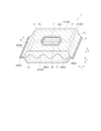
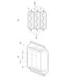
- FIG. 1 is a perspective view of a seat structure according to an embodiment.
- FIG. 2 is a perspective view of the seat structure with the lid removed.
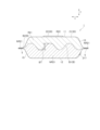
- FIG. 3 is a side view of the seat structure.
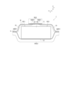
- FIG. 4 is a cross-sectional view of the sheet structure taken along line AA shown in FIG.
- FIG. 5 is a diagram schematically showing an example of the manufacturing process of the sheet structure.
- FIG. 6 is an enlarged view of portion B shown in FIG. 4.
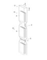
- FIG. 7 is a diagram showing the container according to the embodiment.
- a sheet structure includes a sheet laminate in which a plurality of sheets containing moisture are laminated, and a packaging sheet containing the sheet laminate.
- the packaging sheet includes a matte layer that has been subjected to a matte finish and a vapor deposition layer that has been subjected to a vapor deposition process.
- the packaging sheet since the packaging sheet has the vapor-deposited layer, it is possible to suppress the evaporation of moisture in the encapsulated sheet.
- the packaging sheet has a matte layer.
- the matte layer suppresses light scattering, and the unevenness of the surface gives a feeling that fits your fingers, etc., giving it a luxurious feel and feeling good on the skin. I can give you a kind heart. Therefore, a texture suitable for the added value of the product can be imparted to the packaging sheet. Furthermore, the added value of the product can be sensually conveyed to the user through the packaging sheet. Specifically, for example, we provide a skin-friendly product in which moisture evaporation is suppressed by the vapor deposited layer and the sheet retains sufficient moisture, and a skin-friendly product in which the sheet retains sufficient moisture by the matte layer. I can give you proof that this is the case. That is, while ensuring the quality of the product itself, it is possible to intuitively convey the guaranteed quality to the user.
- a sheet structure includes a sheet laminate in which a plurality of sheets containing moisture are laminated, and a packaging sheet containing the sheet laminate.
- the packaging sheet has a matte layer that has been subjected to a matte finish.
- the water vapor permeability from the inside to the outside of the sheet structure is lower than the water vapor permeability from the outside to the inside of the sheet structure. Since the water vapor permeability from the inside to the outside of the sheet structure is relatively low, the water contained in the sheet is difficult to be released to the outside of the sheet structure, and evaporation of the water in the sheet can be suppressed.
- the packaging sheet has a matte layer.
- the matte layer suppresses light scattering, and the unevenness of the surface gives a feeling that fits your fingers, etc., giving it a luxurious feel and feeling good on the skin. I can give you a kind heart. Therefore, a texture suitable for the added value of the product can be imparted to the packaging sheet. Furthermore, the added value of the product can be sensually conveyed to the user through the packaging sheet. Specifically, for example, by suppressing water vapor permeability from the inside to the outside of the sheet structure, moisture evaporation can be suppressed, and the sheet can provide a skin-friendly product that retains sufficient moisture, while also providing a matte layer. This provides assurance that the sheet is a skin-friendly product that retains sufficient moisture. That is, while ensuring the quality of the product itself, it is possible to intuitively convey the guaranteed quality to the user.
- the sheet structure has a water vapor permeability from the inside to the outside of 0.65 g/m 2 ⁇ day or less.
- the applicant conducted intensive research and found that by having a water vapor permeability of 0.65 g/m 2 ⁇ day or less, evaporation of internal moisture can be effectively suppressed, and the expiration date can be reached within 3 years, which is the standard expiration date. It was found that dissatisfaction with the moisture content of wet tissues can be prevented. Therefore, according to this aspect, it is possible to provide a sheet that sufficiently contains moisture throughout its expiration date.
- the packaging sheet has a matte region where the matte layer is provided and a non-matte region where the matte layer is not provided.
- the boundary between the matte region and the non-matte region has a plurality of curved portions extending in a curved shape. If the boundary extends only in a straight line, the rigidity changes at the boundary, and an unintended straight fold base point is formed in the packaging sheet.
- the folding reference point is divided multiple times at the curved portion, and it is possible to prevent the folding reference points from being continuous. Therefore, it is possible to suppress the formation of unintended linear fold base points on the packaging sheet, maintain the shape of the sheet structure, and continue to protect the internal sheet laminate.
- the packaging sheet has a vapor deposition layer subjected to vapor deposition processing.
- the sheet structure has a front side and a back side facing each other.
- the vapor deposition layer is provided on both the front surface and the back surface.
- the matte layer is provided on the front surface of the front surface and the back surface, and constitutes an outer surface of the packaging sheet.
- the vapor deposition layer is provided on both the front and back surfaces, and evaporation of water in the sheet can be suppressed on both surfaces.
- the matte layer is provided on the front side and constitutes the outer surface of the packaging sheet. Further, no matte layer is provided on the back surface. Therefore, the surface processing on the front and the surface processing on the back are different.
- a matte layer lowers the coefficient of friction on the surface
- transportation during manufacturing may be unstable.
- stability during transport can be improved.
- the texture of the front and the back are different, the user can tell the difference between the front and the back by touch or vision. For example, when a user holds the device between the front and back sides, the difference in texture can be better understood.
- the matte layer lowers the coefficient of friction on the surface, since fingers touch both the front and back surfaces, fingers placed on the back surface are relatively hard to slip and can be held stably.
- the sheet structure has a side surface extending between the front surface and the back surface.
- the packaging sheet has a matte area where the matte layer is provided and a non-matte area where the matte layer is not provided. A boundary between the matte area and the non-matte area is provided on the side surface.
- the side surface has a height direction connecting the front surface and the back surface, and a lateral direction perpendicular to the height direction.
- the boundary has a wave shape having an amplitude in the height direction and extending in the lateral direction. The amplitude is 25% or more of the length of the side surface in the height direction.
- the boundary since the boundary has a wave shape extending in the horizontal direction, the matte regions and the non-matte regions are arranged alternately in the horizontal direction. Furthermore, matte areas and non-matte areas are alternately arranged over an amplitude of 25% or more of the length of the side surface in the height direction. Therefore, even if the user holds the side surface without being aware of the position, the user can easily place his or her fingers across the boundary and can stably hold the sheet structure.
- the packaging sheet includes a sheet main body in which an opening is formed to serve as an outlet for the sheet, and a lid body that freely opens and closes the opening.
- the matte layer is provided on each of the sheet body and the lid.
- the matte layer of the sheet body is a layer in which a matting agent is dispersed.
- the matte layer of the lid is formed by pressing a resin layer to form irregularities.
- the structure of the matte layer is different between the sheet body and the lid body, different textures can be provided. This provides evidence that multiple added values are provided compared to a form with only a matte layer of the same texture.
- the matte layer of the lid is formed by uneven processing, and the lid tends to have deeper irregularities than the sheet body. The unevenness makes it easier for the lid to deform more flexibly, thereby improving the operability of opening and closing the lid.
- the matte layer of the sheet main body is spaced apart from an opening edge surrounding the opening.
- the vicinity of the opening edge is not provided with a matte layer and becomes a non-matte region.
- matte processing applying matte varnish, uneven processing
- minute unevenness is formed, and the adhesive that fixes the lid to the sheet body remains within the unevenness, so that when the lid is opened and closed repeatedly, There is a risk that the adhesive strength of the product may decrease.
- no unevenness is formed by the matte layer near the edge of the opening, it is possible to suppress a decrease in the adhesive strength of the lid.
- the packaging sheet has a first printed layer disposed on the inner surface side of the base material layer, and a second printed layer disposed on the outer surface side than the base material layer.
- the matte layer is arranged on the outer surface side of the base layer.
- the first printed layer is arranged in an area that overlaps with the matte layer
- the second printed layer is arranged in an area that does not overlap with the matte layer.
- the matte layer is placed overlapping the first printed layer and is placed closer to the outer surface than the base layer. Therefore, a matte effect is exhibited on the outer surface of the sheet structure, and the first printed layer and the matte layer are laminated in the thickness direction, so that the texture and aesthetic appearance can be synergistically enhanced.
- the second printed layer is provided in an area that does not overlap with the matte layer, that is, in an area where unevenness due to the matte layer is not formed. Therefore, it is possible to suppress the printing on the second printed layer from being rubbed by the unevenness, and to ensure the visibility of the second printed layer.
- a sheet structure includes a sheet laminate in which a plurality of sheets containing moisture are laminated, and a packaging sheet containing the sheet laminate.
- the packaging sheet has an opening that serves as an outlet for the sheet, and a lid that covers the opening in an openable and closable manner.
- the lid has a matte layer that has been subjected to a matte finish.
- a visual information section is provided in the area where the lid is placed.
- the sheet has hydrophilic fibers. According to this aspect, since the sheet has hydrophilic fibers, the sheet can easily retain moisture, and evaporation of the sheet can be suppressed. Moreover, the lid has a matte layer.
- the matte layer suppresses light scattering, and the unevenness of the surface provides a feeling that feels comfortable on fingers etc., giving it a luxurious feel. It can give you a feeling of being gentle on your skin.
- the visual information section can improve the aesthetic appearance and express added value. Specifically, for example, hydrophilic fibers can suppress moisture evaporation, and the sheet can provide a skin-friendly product that retains sufficient moisture, and the matte layer and visual information area can suppress moisture evaporation. You can be assured that the product is gentle on the skin. That is, while ensuring the quality of the product itself, it is possible to intuitively convey the guaranteed quality to the user.
- the container includes a sheet laminate in which a plurality of sheets having moisture are laminated, a sheet structure encapsulated by a packaging sheet, and a container sheet accommodating an aggregate in which a plurality of the sheet structures are laminated.
- the packaging sheet is provided with a matte region provided with a matte layer subjected to matte processing, and a non-matte region in which the matte layer is not provided.
- the matte layer constitutes the outer surface of the packaging sheet.
- the aggregate has a first sheet structure and a second sheet structure. The matte region of the first sheet structure and the non-matte region of the second sheet structure are in contact with each other.
- the sheet is packaged with a packaging sheet and further accommodated within a storage sheet.
- the packaging sheet has a matte layer and can give a sense of luxury and a feeling of being gentle on the skin. Therefore, a texture suitable for the added value of the product can be imparted to the packaging sheet. Furthermore, the added value of the product can be sensually conveyed to the user through the packaging sheet. While ensuring the quality of the product itself, it is possible to intuitively convey the guaranteed quality to the user. Further, the matte region of the first sheet structure and the non-matte region of the second sheet structure are in contact with each other.
- matte regions abut each other or non-matte regions abut each other over the entire abutting surfaces, they may slip too easily, or they may get caught too much and become difficult to remove.
- the uneven surface of the matte region and the non-irregular surface of the non-matte region engage with each other, thereby suppressing mutual displacement and ensuring ease of removal.
- the accommodation sheet has a matte layer that has been subjected to a matte finish. According to this aspect, visual and tactile effects can be imparted by the matte layer even in the state of the container housing a plurality of sheet structures.
- the accommodation sheet has a layer containing recycled fibers. According to this aspect, high quality and environmentally friendly visual and tactile effects can be provided even in the state of a container housing a plurality of sheet structures.
- FIG. 1 and 2 are perspective views of the seat structure 1.
- FIG. 1 shows the seat structure 1 with the lid 22 not removed
- FIG. 2 shows the seat structure 1 with the lid 22 removed.
- FIG. 3 is a diagram showing a side surface (lateral side surface 17) of the seat structure 1.
- FIG. 4 is a cross-sectional view taken along line AA shown in FIG.
- the sheet structure 1 includes a sheet laminate 50 in which a plurality of sheets 51 containing moisture are laminated, and a packaging sheet 20 containing the sheet laminate 50.
- the sheet structure 1 has a front side 11 and a back side 12 facing each other.
- the front surface 11 may be a surface on which the product name of the sheet structure 1 is written, or may be a surface placed toward a purchaser during display.
- the front surface 11 in this embodiment is a surface on which the openings 7 formed in the packaging sheet 20 are formed.
- the back surface 12 is a surface facing the front surface 11.
- the front side 11 and the back side 12 may extend in the vertical direction X and the horizontal direction Y.
- the sheet structure 1 has a side surface extending in the height direction T connecting a front surface 11 and a back surface 12.
- the side surface has a pair of horizontal side surfaces 17 extending in the horizontal direction Y and the height direction T, and a pair of vertical side surfaces 15 extending in the vertical direction X and the height direction T.
- a packaging joint 5, which will be described later, is provided along the longitudinal direction X on the outer surface of each of the pair of vertical side surfaces 15.
- the sheet structure 1 may have a substantially rectangular parallelepiped shape. Each surface may be a rectangular surface. Furthermore, the surfaces may not intersect perpendicularly at the boundaries where they intersect with each other, but may intersect in a curved manner.
- the sheet 51 of the sheet stack 50 is a sheet containing moisture (for example, wet tissue).
- the sheet laminate 50 may be folded at least along the fold line FL along the lateral direction Y. In the folded state, adjacent sheets 51 in the thickness direction may be alternately arranged.
- the sheet 51 may be folded with a crease extending in the longitudinal direction It may be configured to be partially separable via a line (perforation). The configuration of the sheet 51 will be explained in detail later.
- the packaging sheet 20 includes a sheet laminate 50.
- the packaging sheet 20 may include a sheet main body 21 and a lid body 22.
- the sheet main body 21 may be formed with an opening 7 that serves as an outlet for the sheet 51.
- the lid body 22 closes the opening 7 in an openable and closable manner.
- the opening 7 may be arranged on the front face 11. That is, the surface in which the opening 7 is formed may constitute the front surface 11.
- the dimensions of the opening 7 may be such that each sheet 51 can be pulled out.
- the shape of the opening 7 may be an ellipse, a horizontally long (vertically long) circle, or a perfect circle in plan view, and the shape is not limited.
- the shape of the opening 7 is curved and does not need to have sharp corners in order to prevent the sheet 51 from getting caught.
- the opening 7 may be arranged at the center of the sheet structure 1 in the longitudinal direction X and the center in the lateral direction Y.
- the lid body 22 is configured to cover the opening 7 and has a larger area than the opening 7.
- An adhesive 23 (see FIG. 4) is applied to the surface of the lid 22 facing the sheet body 21, and is releasably bonded to the sheet body 21.
- the material and structure of the packaging sheet 20 will be explained in detail later.
- FIG. 5 is a diagram schematically showing an example of the manufacturing process of the sheet structure 1.
- steps 1 to 4 may be included.
- step 1 (S1) the sheet main body 21 formed in a cylindrical shape is transported in the transport direction MD.
- the lid body 22 is omitted.
- step 2 (S2) after step 1, the sheet stack 50 is placed in the hollow portion of the cylindrical sheet main body 21. Note that the order of steps 1 and 2 may be reversed, and after the sheet laminate 50 is placed on the sheet body 21, the sheet body 21 may be formed into a cylindrical shape.
- step 3 after step 2, the inner side of the sheet main body 21 in the cross direction CD perpendicular to the conveyance direction MD is placed against the side surface (the side surface extending from the lateral side surface 17 in the conveyance direction MD) of the sheet body 21 along the conveyance direction MD.
- the sheet body 21 is folded inward in the cross direction CD by pushing the pressing member toward the sheet body 21.
- step 4 after step 3, the folded sheet bodies 21 are joined together to form the packaging joint portion 5.
- the packaging joint portion 5 is formed over the entire area of the sheet structure 1 in the cross direction (vertical direction X) CD.
- the packaging joint part 5 is folded between a two-layer part where two sheet bodies 21 are joined, a sheet body 21 on the front side 11 side and a sheet body 21 on the back side 12 side, and the two sheet bodies 21.
- the seat body 21 has a four-layer portion in which the four-layer sheet body 21 is sandwiched and the four-layer sheet body 21 is joined.
- the folded sheet main bodies 21 extend inward in the longitudinal direction X between the two sheet main bodies 21.
- a cutting step not shown
- the packaging joint portion 5 is cut at the center in the conveyance direction along the longitudinal direction X, thereby obtaining individual sheet structures 1.
- the sheet structure 1 of this embodiment is configured to be able to suppress evaporation of moisture in the sheet 51 before use, and to impart a texture to the packaging sheet 20 that matches the added value of the product.
- the first to third embodiments for suppressing the evaporation of moisture in the sheet 51 before use and imparting a texture to the packaging sheet 20 that matches the added value of the product will be described in detail.
- a common structure will abbreviate
- FIG. 6 is an enlarged sectional view of portion B shown in FIG. 4, and is a diagram schematically showing the configuration of the seat body 21. As shown in FIG. Although FIG. 6 shows the layers constituting the sheet body 21 as being partially separated, in reality, the layers are in contact with each other.
- the packaging sheet 20 includes at least a matte layer 211 that has been subjected to a matte finish and a vapor deposition layer 212 that has been subjected to a vapor deposition process.
- the sheet body 21 has a matte layer 211 and a vapor deposited layer 212
- the lid body 22 has a matte layer 211 and does not have a vapor deposited layer 212. That is, the matte layer 211 and the vapor deposition layer 212 may be disposed on at least a portion of the packaging sheet 20. Further, the matte layer 211 and the vapor deposited layer 212 may or may not overlap in the thickness direction.
- the state in which two members overlap is not only the state in which the two members are in contact and overlap, but also the state in which the two members are not in contact but indirectly through another member or space. This also includes situations in which the
- the matte layer 211 is a layer in which fine irregularities are formed and gives a matte texture.
- the matte layer 211 may be, for example, a resin layer in which a matting agent is dispersed. Examples of matting agents include silica, alumina, calcium oxide, calcium carbonate, calcium sulfate, calcium silicate, and carbon black.
- the resin layer is formed from, for example, an acrylic resin, an epoxy resin, a urethane resin, a polyolefin resin, a fluororesin, a phenoxy resin, or a silicone resin.
- the matte layer 211 may be formed by OP (overprint) varnish processing by printing matte varnish. Further, the matte layer 211 may be a layer obtained by subjecting a resin layer such as a film to pressure processing such as embossing to form irregularities.
- the packaging sheet 20 may have a base material layer 213, and the matte layer 211 may be laminated on the base material layer 213.
- the matte layer 211 may be formed by applying a matte varnish to the base layer 213.
- the base material layer 213 may be made of polyolefin resin or polyester resin.
- the matte layer 211 of this embodiment is arranged on the outer surface side T1 of the base material layer 213, and constitutes the outer surface of the sheet body 21 and the outer surface of the lid body 22. Therefore, the visual effect of the matte layer 211 can be better exhibited from the outside of the sheet structure 1, and the tactile sensation of the matte layer 211 can also be imparted to the user.
- the matte layer 211 does not need to constitute the outer surface of the sheet main body 21, does not need to constitute the outer surface of the lid body 22, or is arranged on the inner surface side T2 of the base material layer 213. may have been done.
- the vapor deposition layer 212 may be laminated on the matte layer 211 itself without interposing the base layer 213.
- the matte layer 211 may be arranged on the outer surface side T1 of the base material layer 213, and the vapor deposition layer 212 may be arranged on the inner surface side T2 of the base material layer 213.
- the matte layer 211 has an uneven shape, since the base layer 213 is arranged between the matte layer 211 and the vapor deposited layer 212, the arrangement of the vapor deposited layer 212 and the matte layer 211 can be stabilized.
- the vapor deposited layer 212 is a layer in which a metal, oxide, or the like is evaporated onto a base material (for example, the base material layer 213) and adhered to the surface of the base material.
- alumina deposition aluminum oxide
- silica deposition silicon oxide
- aluminum deposition aluminum
- water vapor permeability can be lowered and evaporation of water in the sheet 51 can be suppressed.
- the matte layer 211 and the vapor deposition layer 212 may overlap or may not partially overlap.
- the vapor deposition layer 212 of this embodiment is provided on the entire surface of the sheet body 21 and is not provided on the lid body 22.
- the matte layer 211 is provided in a part of the sheet body 21 and on the entire surface of the lid 22.
- the vapor deposition layer 212 may be provided on the entire surface or a part of the lid 22.
- the matte layer 211 may be provided on the entire surface of the sheet body 21 or may be provided on a part of the lid body 22.
- the packaging sheet 20 has a matte layer 211 and a vapor deposited layer 212. Since the packaging sheet 20 has the vapor deposited layer 212, evaporation of moisture in the enclosed sheet 51 can be suppressed. Furthermore, the packaging sheet 20 has a matte layer 211.
- the matte layer 211 generally suppresses light scattering compared to a structure that does not include the matte layer 211. Further, in the case where the matte layer 211 is disposed on the outer surface of the packaging sheet 20, the unevenness of the surface can provide a feeling that the matte layer 211 is comfortable to the fingers or the like. Therefore, the packaging sheet 20 can give a feeling of luxury and a sense of being gentle on the skin.
- the added value of the product can be sensually conveyed to the user through the packaging sheet 20.
- the evaporation layer 212 can suppress moisture evaporation
- the sheet 51 can sufficiently retain moisture to provide a skin-friendly product
- the matte layer 211 can suppress moisture in the sheet 51. This will give you confidence that the product is gentle on your skin. That is, while ensuring the quality of the product itself, it is possible to intuitively convey the guaranteed quality to the user.
- the packaging sheet 20 according to the second embodiment has a matte layer 211.
- the sheet structure 1 according to the second embodiment has a water vapor permeability from the inside of the sheet structure 1 (inner surface side of the sheet structure 1) to the outside (outer surface side of the sheet structure 1) from the outside of the sheet structure 1. Lower than the water vapor permeability to the inside.
- the packaging sheet 20 according to the second embodiment only needs to satisfy the water vapor permeability, and does not need to have the vapor deposited layer 212. Note that the water vapor permeability may be satisfied as long as the opening 7 of the sheet body 21 is closed with the lid 22, that is, in an unopened state.
- the structure for making the water vapor permeability from the inside to the outside of the sheet structure 1 lower than the water vapor permeability from the outside to the inside of the sheet structure includes the basis weight, material, and adhesive structure of each layer of the packaging sheet 20.
- the layer structure of the film includes a polyolefin of 20 to 40 ⁇ m from the inside, a vapor deposition layer (for example, alumina vapor deposition (aluminum oxide), silica vapor deposition (silicon oxide), vapor deposition of a combination of alumina vapor deposition and silica vapor deposition, aluminum vapor deposition (aluminum)),
- a packaging sheet is prepared by laminating polyolefin or polyester with a thickness of 10 to 25 ⁇ m as the outermost layer.
- the sheet structure 1 according to the second embodiment has a relatively low water vapor permeability from the inside to the outside of the sheet structure 1, it is difficult for the water contained in the sheet 51 to be released to the outside of the sheet structure 1. It is possible to suppress the evaporation of 51 moisture.
- the packaging sheet 20 has the matte layer 211, the visual and tactile effects of the matte layer 211 can be obtained. Therefore, the packaging sheet 20 according to the second embodiment can also provide the packaging sheet 20 with a texture that matches the added value of the product. Furthermore, the added value of the product can be sensually conveyed to the user through the packaging sheet 20.
- the water vapor permeability can be measured using a water vapor permeability measuring device "PERMATRAN-W" (registered trademark) 3/30 manufactured by MOCON/Modern Controls under conditions of a temperature of 40°C and a humidity of 90% RH. (Unit: g/m 2 /day).
- PERMATRAN-W registered trademark
- MOCON/Modern Controls under conditions of a temperature of 40°C and a humidity of 90% RH. (Unit: g/m 2 /day).
- the packaging sheet 20 according to the third embodiment has a lid 22.
- the lid body 22 has a matte layer 211 that has been subjected to a matte finish.
- a visual information section 25 is provided in the area where the lid 22 is placed.
- the sheet has hydrophilic fibers.
- the sheet 51 only needs to contain at least hydrophilic fibers, and may contain other fibers. Hydrophilic fibers are not particularly limited, and examples include cotton fibers, natural cellulose fibers, and rayon fibers. Note that the packaging sheet 20 according to the third embodiment does not need to have the vapor deposition layer 212.
- the region where the lid 22 is arranged includes the region of the lid 22 itself and the sheet body 21 overlapping with the lid 22.
- the visual information section 25 only needs to be visible from the outer surface side of the sheet structure 1, and may be attached to the lid body 22 itself by printing or the like, or attached to the sheet body 21 and attached to a transparent or translucent lid. It may be configured so that it can be visually recognized through the body 22.
- the visual information section 25 may be information indicating the added value of the sheet structure 1, such as information with an image of nature indicating that it contains ingredients derived from nature (such as a cotton design), or information indicating that the sheet contains plenty of moisture. Information that represents the image of water (colors that represent drops or water) can be exemplified.
- the visual information section 25 of this embodiment has a cotton design.
- the lid body 22 has a matte layer 211.
- the matte layer 211 can suppress light scattering and give a feeling of fitting to a finger etc. due to the unevenness of the surface, compared to a non-matte area that generally does not have a matte layer. It can give you a feeling of being gentle on your skin and skin.
- hydrophilic fibers can suppress moisture evaporation
- the sheet can provide a skin-friendly product that retains sufficient moisture
- the matte layer and visual information area can suppress moisture evaporation. You can be assured that the product is gentle on the skin. That is, while ensuring the quality of the product itself, it is possible to intuitively convey the guaranteed quality to the user.
- the sheet structure 1 according to the first to third forms will be described.
- the water vapor permeability from the inside to the outside of the sheet structure 1 may be lower than the water vapor permeability from the outside to the inside of the sheet structure.
- the packaging sheet 20 according to the second form and the third form may also have a vapor deposited layer 212.
- the sheet structure 1 according to the first and second embodiments may also include the lid 22 and the visual information section 25, or the sheet 51 may include hydrophilic fibers.
- the sheet structure 1 has a water vapor permeability from the inside to the outside of the sheet structure 1 of 0.65 g/m 2 ⁇ day or less.
- the applicant conducted intensive research and found that by having a water vapor permeability of 0.65 g/m 2 ⁇ day or less, evaporation of internal moisture can be effectively suppressed, and the expiration date can be reached within 3 years, which is the standard expiration date. It was found that dissatisfaction with the moisture content of wet tissues can be prevented. Therefore, according to this aspect, it is possible to provide the sheet 51 that sufficiently contains moisture throughout the expiration date.
- the packaging sheet 20 may have matte regions R21 and R22 where the matte layer 211 is provided and a non-matte region NR21 where the matte layer 211 is not provided.
- the sheet body 21 is provided with a matte region R21 and a non-matte region NR21
- the lid body 22 is provided with only a matte region R21 and a non-matte region NR21. It has not been done.
- the matte region R22 of the lid body 22 is shown with diagonal lines.
- the matte region R21 and the non-matte region NR21 of the sheet body 21 are shown with diagonal lines.
- the matte regions R21 and R22 of this embodiment are the front surface 11 (excluding the region overlapping the packaging joint 5 and the vicinity of the opening edge), and the region on the front surface 11 side of each of the four side surfaces (the upper region in FIG. 2). (excluding the area overlapping the packaging joint part 5).
- the matte layer 211 is not provided on the back surface 12.
- the non-matte area NR21 of this embodiment is provided in the entire area of the back surface 12 and in each of the four side surfaces on the back surface 12 side (the lower region in FIG. 2).
- the boundary B between the matte region R21 and the non-matte region NR21 in this embodiment includes a first boundary B1 provided on a pair of horizontal side surfaces 17, a second boundary B2 provided on a pair of vertical side surfaces 15, has.
- the first boundary B1 has a wave shape that continues in the horizontal direction Y, and the boundary B of the vertical side surface 15 is linear and extends along the outer edge of the packaging joint 5.
- the first boundary B1 as the boundary B may have a plurality of curved portions extending in a curved shape. If the boundary extends only in a straight line, the rigidity changes at the boundary, and an unintended straight fold base point is formed in the packaging sheet 20.
- the first boundary B1 provided with a plurality of curved parts even if a folding base point is formed at the first boundary B1, the folding base point will be divided multiple times at the curved part, and the folding base point will be Continuation can be suppressed. Therefore, it is possible to suppress the formation of unintended linear fold base points in the packaging sheet 20, maintain the shape of the sheet structure 1, and continue to protect the sheet laminate 50 inside.
- the first boundary B1 has a wavy shape with a plurality of continuous arc-shaped curved parts. Therefore, the first boundary B1 is configured by only continuous curved portions. However, in a modified example, the first boundary B1 may be configured by a combination of a curved part and a straight part. Furthermore, in the case where the matte region R21 is formed by applying matte varnish, the amount of matte varnish applied gradually decreases toward the non-matte region NR21, and the matte regions R21 and R22 form a gradation. There is. In this configuration, a portion to which even a small amount of matte varnish is applied is defined as a boundary B between the matte regions R21 and R22.
- the vapor deposition layer 212 may be provided on both the front side 11 and the back side 12. According to this configuration, evaporation of water in the sheet 51 can be suppressed on both the front surface 11 and the rear surface 12, which have relatively large areas.
- the matte layer 211 (matte regions R21, R22) may be provided on the front surface 11 and may not be provided on the back surface 12.
- the matte layer 211 constitutes the outer surface of the sheet body 21 as the packaging sheet 20. Therefore, the surface treatment of the front surface 11 and the surface treatment of the rear surface 12 are different. For example, if the matte layer 211 lowers the coefficient of friction on the surface of the packaging sheet 20, transportation during manufacturing may not be stable. However, by transporting with the back surface 12 in contact with the transport surface, stability during transport can be improved.
- the user can tell the difference between the front surface 11 and the back surface 12 by touch or vision. For example, when a user holds the front side 11 and the back side 12, the user can recognize the difference in texture and can tell the difference between the front side 11 and the back side 12. Furthermore, even if the coefficient of friction of the surface is lowered by the matte layer 211, since the fingers touch both the front surface 11 and the back surface 12, the fingers placed on the back surface 12 are relatively hard to slip and can be held stably. can.
- the boundary B between the matte region R21 and the non-matte region NR21 may be provided on the side surface.
- the user can grasp the difference in texture.
- the fingers touch the non-matte area NR21, the fingers are relatively hard to slip, and the sheet structure 1 can be held stably.
- the first boundary B1 having the curved portion may be provided on the side surface 17 where the packaging joint 5 is not provided.
- a user may hold the sheet structure 1 so as to grasp the lateral sides where the packaging joint 5 is not provided. At this time, since the fingers hit the non-matte area, the fingers are relatively hard to slip, and the sheet structure can be stably held.
- the first boundary B1 has an amplitude BT in the height direction and has a wave shape extending in the horizontal direction, and the amplitude may be 25% or more of the length of the side surface in the height direction. Since the first boundary B1 has a wave shape extending in the horizontal direction, matte areas and non-matte areas are arranged alternately in the horizontal direction. Furthermore, matte areas and non-matte areas are alternately arranged over an amplitude of 25% or more of the length of the side surface in the height direction. Therefore, even if the user holds the side surface without being aware of the position, the user can easily place his or her fingers across the boundary and can stably hold the sheet structure.
- the amplitude at the longest position may be 25% or more of the length in the height direction of the side surface.
- the length of the side surface in the height direction may be determined by placing the sheet structure 1 on a flat table and placing the left and right packaging joints 5 horizontally. The maximum length in the height direction T is obtained when the material is pulled outward in the direction T.
- the non-matte region NR21 may be provided in a region overlapping the packaging joint portion 5. That is, the matte layer 211 does not need to be provided in the area overlapping the packaging joint 5.
- the sheet main body 21 is heated from its outer surface side to fuse the heat-sealing resin layer 216 (see FIG. 6). At this time, since the matte layer 211 is not provided in the region to be heated, it is possible to prevent the matte varnish forming the matte layer 211 from adhering to the heating member.
- the matte layer 211 may be provided on each of the sheet main body 21 and the lid body 22.
- the user When using the sheet 51, the user operates the lid 22 while holding the sheet body 21, and takes out the sheet 51 through the opening 7.
- the matte layer 211 is provided on the lid body 22 that the user focuses on and operates, and the matte layer 211 is provided on the sheet body 21 that the user operates, the user can Through 211, it is easier to get a sense of luxury and skin-friendly feeling.
- the structure of the matte layer 211 of the sheet body 21 and the structure of the matte layer 211 of the lid body 22 may be different. Since the structure of the matte layer 211 is different between the sheet body 21 and the lid body 22, different textures can be provided. Compared to a form with only the matte layer 211 having the same texture, it is possible to give the user a feeling that multiple added values are provided.
- the matte layer 211 of the sheet body 21 may be a layer in which a matting agent is dispersed, and the matte layer 211 of the lid body 22 may be a layer formed by pressing a resin layer to form irregularities.
- the matte layer 211 of the lid body 22 is formed by uneven processing, and the lid body 22 tends to have deeper irregularities than the sheet body 21.
- the unevenness makes it easier for the lid body 22 to deform more flexibly, and the operability of opening and closing the lid body 22 can be improved.
- the matte layer 211 of the sheet body 21 is a layer in which a matting agent is dispersed, finer unevenness is more likely to be formed on the sheet body 21 than on the lid body 22. Therefore, the roughness when holding and carrying the sheet body 21 can be suppressed, and the user can be assured that the product is supple and gentle on the skin.
- the matte layer 211 of the sheet body 21 may be spaced apart from the opening edge 7E surrounding the opening 7. More specifically, a non-matte area NR21 may be provided in a certain area (area in contact with the adhesive) extending outward in the planar direction from the opening edge 7E. The vicinity of the opening edge 7E is not provided with the matte layer 211, and becomes a non-matte region NR21.
- the matte finish is applied, fine irregularities are formed, and the adhesive for fixing the lid 22 to the sheet body 21 remains within the irregularities, and the adhesive strength of the lid 22 is reduced when the lid 22 is repeatedly opened and closed. There is a risk that it will decrease. However, since no unevenness is formed by the matte layer near the opening edge 7E, a decrease in the adhesive strength of the lid body 22 can be suppressed.
- the packaging sheet 20 includes a first printed layer 214 disposed on the inner surface side T2 of the base material layer 213, and a second printed layer 217 (see FIG. 3) disposed on the outer surface side T1 of the base material layer 213. may have.
- the first printed layer 214 may be arranged in an area overlapping with the matte layer 211, and the second print layer 217 may be arranged in an area not overlapped with the matte layer 211.
- the sheet main body 21 has a first printed layer 214 and a second printed layer 217.
- the first printed layer is arranged on the inner surface side T2 of the vapor deposition layer 212 and on the outer surface side of the adhesive layer 215.
- the first printed layer 214 is arranged over substantially the entire sheet body 21 .
- the first printed layer 214 is arranged in both a region that overlaps with the matte layer 211 (matte region R21) and a region that does not overlap with the matte layer 211 (non-matte region NR21).
- a second printed layer 217 is arranged on the back surface 12. That is, the second printed layer 217 is arranged only in the non-matte region NR21.
- the matte layer 211 is arranged to overlap the first printed layer 214 and is arranged on the outer surface side T1 than the base material layer 213. Therefore, a matte effect is exhibited on the outer surface of the sheet structure 1, and the first printed layer 214 and the matte layer 211 are laminated in the thickness direction, so that the texture and aesthetic appearance can be synergistically enhanced.
- the second printed layer 217 is provided in an area that does not overlap with the matte layer 211, that is, in an area where unevenness due to the matte layer 211 is not formed. Therefore, the printing on the second printed layer 217 is prevented from being rubbed by the unevenness, and the visibility of the second printed layer 217 can be ensured.
- the sheet body 21 of this embodiment includes, from the outer side T1 to the inner side T2, a matte layer 211, a base material layer 213, a vapor deposition layer 212, a first printed layer 214, and an adhesive layer. 215 and a heat-sealing resin layer 216 are laminated in this order.
- the adhesive layer 215 adheres the heat-sealing resin layer 216 and the layer on the base material layer 213 side.
- the heat-sealing resin layer 216 is a layer in which a heat-sealing resin for bonding the sheet bodies 21 to each other is disposed, and is fused at the packaging joint portion 5 to bond the sheet bodies 21 to each other.
- the second printed layer 217 is arranged on the outer surface side of the matte layer 211.
- the second printed layer 217 may be made of ink, for example, and may indicate manufacturing information such as the lot number of the sheet structure.
- FIG. 7(a) is a perspective view of the container 100
- FIG. 7(b) is a side view of the assembly.
- the storage body 100 includes a sheet structure 1 and a storage sheet 101 that stores an assembly in which a plurality of sheet structures 1 are stacked.
- the assembly includes a plurality of sheet structures 1 stacked together, and the assembly of this embodiment includes a first sheet structure 1X, a second sheet structure 1Y, and a third sheet structure 1Z. Note that the assembly may be composed of only the first sheet structure 1X and the second sheet structure 1Y, or may have four or more sheet structures.
- the sheet structures 1 overlap in the height direction T, and the back surface 12 of the first sheet structure 1X and the front surface 11 of the second sheet structure 1Y may be in contact with each other.
- the aggregates may overlap in the vertical direction X or the horizontal direction Y, and the side surface of the first sheet structure 1X and the side surface of the second sheet structure 1Y may abut.
- the storage sheet 101 is a sheet that stores the aggregate, and may be formed into a bag shape.
- the accommodation sheet 101 can be configured, for example, by a matte film whose surface is textured, or a film made by pasting a sealant layer on rayon paper containing rayon and pulp.
- the sheet 51 is wrapped by the packaging sheet 20 and further accommodated in the storage sheet 101. Since the sheet 51 is covered multiple times, evaporation of moisture in the sheet 51 can be suppressed.
- the packaging sheet 20 has a matte layer 211, and the matte layer 211 constitutes the outer surface of the packaging sheet 20. Therefore, a texture suitable for the added value of the product can be imparted to the packaging sheet 20. Furthermore, the added value of the product can be sensually conveyed to the user through the packaging sheet 20.
- the sheet 51 can provide a skin-friendly product that retains sufficient moisture
- the matte layer 211 can provide assurance that the sheet 51 is a skin-friendly product that retains sufficient moisture. . That is, while ensuring the quality of the product itself, it is possible to intuitively convey the guaranteed quality to the user.
- the non-matte region NR21 of the first sheet structure 1X and the matte region R21 of the second sheet structure 1Y are in contact with each other. If matte regions abut each other or non-matte regions abut each other over the entire abutting surfaces, they may slip too easily, or they may get caught too much and become difficult to remove. However, the concavo-convex surface of the matte region R21 and the non-concave and convex surface of the non-matte region NR21 are engaged with each other, and it is possible to suppress mutual displacement and ensure ease of removal.
- a non-matte region NR21 is provided on the entire back surface 12 of the first sheet structure 1X
- a matte region R21 is provided on the entire front surface 11 of the second sheet structure 1Y
- the first sheet The matte region R21 and the non-matte region NR21 are in contact with each other over the entire contact surfaces of the structure 1X and the second sheet structure 1Y.
- the matte region R21 and the non-matte region NR21 may come into contact with each other in a part of the contact surfaces of the first sheet structure and the second sheet structure 1Y.
- the accommodation sheet 101 may have a matte layer that has been subjected to a matte finish. According to this aspect, visual and tactile effects can be provided by the matte layer even in the state of the container 100 that accommodates a plurality of sheet structures 1.
- the matte layer of the accommodation sheet 101 preferably constitutes the outer surface of the accommodation sheet 101.
- the matte layer of the accommodation sheet 101 can have the same structure as the matte layer of the packaging sheet 20, but may be different from the matte layer of the packaging sheet 20.
- the accommodation sheet 101 may have a layer containing recycled fibers. According to this aspect, even in the state of the container 100 that accommodates a plurality of sheet structures 1, high quality and environmentally friendly visual and tactile effects can be provided.
- recycled fibers include rayon, cupro, Lyocell/Tencel, and polynosic.
- the sheet 51 may be made of a laminated nonwoven fabric.
- the laminated nonwoven fabric includes a first surface layer, a second surface layer, and an intermediate layer disposed between them.
- the intermediate layer is mainly composed of hydrophilic fibers. Examples of hydrophilic fibers include cellulose fibers, such as pulp fibers, natural fibers such as cotton, regenerated cellulose fibers such as rayon, purified cellulose fibers, and semi-synthetic cellulose fibers.
- the intermediate layer may include hydrophilic fibers and 5% by mass or more and less than 20% by mass of heat-fusible fibers.
- the intermediate layer preferably contains heat-fusible fibers in a proportion of 7 to 18% by weight, more preferably 8 to 17% by weight, and even more preferably 8 to 16% by weight.
- the heat-fusible fiber has a mutually bonded part.
- the intermediate layer may be composed of hydrophilic fibers and heat-fusible fibers, and may further include other fibers, such as hydrophobic fibers. Note that the hydrophobic fibers will be explained in the first surface layer and second surface layer.
- Each of the first surface layer and the second surface layer contains hydrophobic fibers and hydrophilic fibers, and does not contain heat-fusible fibers. Therefore, in combination with the structure of the intermediate layer, when the laminated nonwoven fabric of the present disclosure is used as a wet tissue, the user will easily feel the smoothness and it will be difficult to twist.
- the hydrophilic fibers constituting each of the first surface layer and the second surface layer are not particularly limited, and from the viewpoint of liquid dispersibility, strength, flexibility, versatility, etc., the materials listed for the intermediate layer can be used.
- cellulose fibers those other than pulp fibers, regenerated cellulose fibers, purified cellulose fibers, and semi-synthetic cellulose fibers are preferred.
- rayon fibers are preferred from the viewpoint of liquid diffusivity, strength after entanglement, ease of handling, versatility, etc.
- the rayon fibers preferably have an average fiber length of 20 to 80 mm, more preferably 30 to 60 mm, and even more preferably 35 to 50 mm. This is from the viewpoint that the rayon fibers become intertwined with each other, increasing the strength of the laminated nonwoven fabric and, ultimately, the wet tissue.
- the hydrophilic fibers constituting each of the first surface layer and the second surface layer further include cotton fibers.
- cotton fibers Compared to short fibers such as pulp fibers, cotton fibers have a smaller number of ends per unit mass, so they can improve liquid retention.
- the laminated nonwoven fabric can improve liquid retention when used as a wet tissue.
- the cotton having a predetermined fiber length is This is because it is difficult to move from the surface and tends to remain on the surface.
- the cotton fibers preferably have an average fiber length of 20 mm or more and less than 30 mm, more preferably 22 to 28 mm. By using cotton fibers with a fiber length of a certain length or more, liquid retention can be improved.
- the cotton fibers include Hirstum cotton (for example, upland cotton), Barbadense cotton, Arboreum cotton, and Helbachaeum cotton.
- the above-mentioned cotton can be organic cotton or pre-organic cotton (trademark).
- Organic cotton means cotton that has been certified as organic cotton such as GOTS (Global Organic Textile Standard).
- the above-mentioned hydrophobic fibers are fibers that are not intended to be heat-fused, and have a softening temperature, melting point, etc. higher than that of the resin constituting the surface of the above-mentioned heat-fusible fibers.
- the fibers include resin fibers such as nylon, polyester, and pyriethylene terephthalate, or composite fibers made by combining thermoplastic fibers thereof.
- the hydrophobic fibers preferably have an average fiber length of 30 mm to 60 mm. When the average fiber length of the hydrophobic fibers is within this range, a web can be easily formed using a carding machine. Further, the hydrophobic fiber preferably has a fineness of 0.6 to 2.2 dtex. When the fineness of the hydrophobic fibers is less than 0.6 dtex, it is difficult to form a web using a carding machine, resulting in a decrease in productivity, while when the fineness of the hydrophobic fibers exceeds 2.2 dtex, , there is a problem that the touch becomes hard.
- each of the first surface layer and the second surface layer preferably has a weight of 5 to 25 g/m 2 , from the viewpoint of the flexibility of the laminated nonwoven fabric, the texture, the diffusivity of the chemical solution, the sheet strength, etc. More preferably, it has a basis weight of 10 to 20 g/m 2 , and even more preferably 11 to 17 g/m 2 .
- the present invention it is possible to provide a sheet structure and a container that can suppress the evaporation of moisture in the sheet before use and can give the packaging sheet a texture that matches the added value of the product.
- Sheet structure 7 Opening 7E: Opening edge 5: Packaging joint 11: Front 12: Back 15: Vertical side 17: Lateral side 20: Packaging sheet 21: Sheet body 22: Lid 25: Visual information section 50: Sheet laminate 51: Sheet 211: Matte layer 212: Vapor deposited layer B: Boundary R21, R22: Matte region NR21: Non-matte region T: Height direction X: Vertical direction Y: Lateral direction
Landscapes
- Engineering & Computer Science (AREA)
- Health & Medical Sciences (AREA)
- Public Health (AREA)
- Mechanical Engineering (AREA)
- Epidemiology (AREA)
- General Health & Medical Sciences (AREA)
- Food Science & Technology (AREA)
- Laminated Bodies (AREA)
- Packages (AREA)
- Containers And Packaging Bodies Having A Special Means To Remove Contents (AREA)
- Wrappers (AREA)
Abstract
使用前のシートの水分の蒸発を抑制でき、かつ製品の付加価値に合った質感を包装シートに付与できるシート構造体を提供する。シート構造体(1)は、水分を有するシート(51)が複数積層されたシート積層体(50)と、シート積層体(1)を内包した包装シート(20)と、を有する。包装シート(20)は、艶消し加工が施された艶消し層(211)と、蒸着加工が施された蒸着層(212)と、を備える。
Description
本発明は、ウェットティッシュ等のシートを積層したシート積層体を、包装シートによって包装したシート構造体及び、当該シート構造体を複数収容した収容体に関する。
シートを複数積層したシート積層体と、シート積層体を包装する包装シートと、を有するシート構造体が提供されている(例えば、特許文献1参照)。シート構造体には、シートの取出口となる開口が形成されている。開口は、蓋部によって開閉可能に覆われている。開口は、使用前に蓋部によって覆われている。使用者は、使用時に、蓋部を開き、開口を介してシートを取り出す。
開口が蓋部によって覆われた状態では、シート構造体は、内包されており、使用前にシートの水分の蒸発することを抑制されている。しかし、時間の経過に伴い包装シートを介して水分がシート外に放出することがあり、シートの水分の蒸発をより抑制することが求められている。
また、近年、肌に対して優しい製品、環境に配慮した製品等、シート自体の機能のみならず、更なる付加価値を有する製品が求められている。当該付加価値を有する製品においては、当該付加価値に合った質感を包装シートに付与することで、使用者の付加価値に対する満足度を高めやすい。そのため、製品であるシート構造体を収容する包装シートの質感を高めることが求められている。
本発明は、上述の問題に鑑みてなされてものであり、使用前のシートの水分の蒸発を抑制でき、かつ製品の付加価値に合った質感を包装シートに付与できるシート構造体、及び収容体を提供することを目的とする。
一態様にかかるシート構造体は、水分を有するシートが複数積層されたシート積層体と、前記シート積層体を内包した包装シートと、を有する。前記包装シートは、艶消し加工が施された艶消し層と、蒸着加工が施された蒸着層と、を備える。
他態様にかかるシート構造体は、水分を有するシートが複数積層されたシート積層体と、前記シート積層体を内包した包装シートと、を有する。前記包装シートは、艶消し加工が施された艶消し層を有する。前記シート構造体の内側から外側への水蒸気透過度は、前記シート構造体の外側から内側への水蒸気透過度よりも低い。
更に他態様にかかるシート構造体は、水分を有するシートが複数積層されたシート積層体と、前記シート積層体を内包した包装シートと、を有する。前記包装シートは、前記シートの取出口となる開口と、前記開口を開閉自在に覆う蓋体と、を有する。前記蓋体は、艶消し加工が施された艶消し層を有する。前記蓋体が配置された領域には、視覚情報部が設けられている。前記シートは、親水性繊維を有する。
一態様にかかる収容体は、水分を有するシートが複数積層されたシート積層体を、包装シートによって内包されたシート構造体と、前記シート構造体が複数積層された集合体を収容した収容シートと、を有する。前記包装シートの外面には、艶消し加工が施された艶消し層が設けられた艶消し領域と、前記艶消し層が設けられていない非艶消し領域と、が設けられている。前記艶消し層は、前記包装シートの外面を構成している。前記集合体は、第1シート構造体と第2シート構造体を有する。前記第1シート構造体の前記艶消し領域と、前記第2シート構造体の前記非艶消し領域と、が当接している。
(1)実施形態の概要
本明細書及び添付図面の記載により、少なくとも以下の事項が明らかとなる。
一態様にかかるシート構造体は、水分を有するシートが複数積層されたシート積層体と、前記シート積層体を内包した包装シートと、を有する。前記包装シートは、艶消し加工が施された艶消し層と、蒸着加工が施された蒸着層と、を備える。本態様によれば、包装シートが蒸着層を有するため、内包されたシートの水分の蒸発を抑制できる。また、包装シートは、艶消し層を有する。艶消し層は、一般的に艶消し層を有しない構成と比較して、光の散乱が抑制されたり、表面の凹凸によって指等に馴染むような感覚を付与したりでき、高級感や肌に優しい心証を与えることができる。よって、製品の付加価値に合った質感を包装シートに付与できる。更に、包装シートを介して製品の付加価値を使用者に感覚的に伝えることができる。具体的には、例えば、蒸着層によって水分の蒸発を抑制でき、シートが水分を十分に保持した肌に優しい製品を提供し、かつ艶消し層によってシートが水分を十分に保持した肌に優しい製品である心証を与えることができる。すなわち、製品自体の品質を担保しつつ、その担保した品質を使用者に感覚的に伝えることができる。
他態様にかかるシート構造体は、水分を有するシートが複数積層されたシート積層体と、前記シート積層体を内包した包装シートと、を有する。前記包装シートは、艶消し加工が施された艶消し層を有する。前記シート構造体の内側から外側への水蒸気透過度は、前記シート構造体の外側から内側への水蒸気透過度よりも低い。シート構造体の内側から外側への水蒸気透過度が比較的低いため、内包されたシートの水分がシート構造体外に放出され難く、シートの水分の蒸発を抑制できる。また、包装シートは、艶消し層を有する。艶消し層は、一般的に艶消し層を有しない構成と比較して、光の散乱が抑制されたり、表面の凹凸によって指等に馴染むような感覚を付与したりでき、高級感や肌に優しい心証を与えることができる。よって、製品の付加価値に合った質感を包装シートに付与できる。更に、包装シートを介して製品の付加価値を使用者に感覚的に伝えることができる。具体的には、例えば、シート構造体の内側から外側への水蒸気透過度を抑えることで水分の蒸発を抑制でき、シートが水分を十分に保持した肌に優しい製品を提供し、かつ艶消し層によってシートが水分を十分に保持した肌に優しい製品である心証を与えることができる。すなわち、製品自体の品質を担保しつつ、その担保した品質を使用者に感覚的に伝えることができる。
好ましい一態様によれば、前記シート構造体の内側から外側への水蒸気透過度は、0.65g/m2・day以下である。出願人が鋭意研究を行ったところ、水蒸気透過度は、0.65g/m2・day以下であることにより、内部の水分の蒸発を効果的に抑制でき、使用期限目安とされる3年間内のウェットティッシュにおける水分率の不満を防ぐことができることがわかった。よって、本態様によれば、使用期限内に亘って水分を十分に含むシートを提供できる。
好ましい一態様によれば、前記包装シートは、前記艶消し層が設けられた艶消し領域と、前記艶消し層が設けられていない非艶消し領域と、を有する。前記艶消し領域と前記非艶消し領域の境界は、曲線状に延びる曲線部を複数有する。境界が直線状にのみ延びる形態に合っては、当該境界で剛性が変化し、包装シートに意図しない直線状の折り基点が形成される。これに対して、曲線部が複数設けられているため、仮に境界にて折り基点が形成されても、その折り基点が曲線部において複数回分断し、折り基点が連続することを抑制できる。よって、包装シートに意図しない直線状の折り基点が形成されることを抑制し、シート構造体の形状を維持し、内部のシート積層体を保護し続けることができる。
好ましい一態様によれば、前記包装シートは、蒸着加工が施された蒸着層を有する。前記シート構造体は、互いに対向する正面及び背面を有する。前記蒸着層は、前記正面及び前記背面の両方に設けられている。前記艶消し層は、前記正面及び前記背面のうち前記正面に設けられ、かつ前記包装シートの外面を構成している。本態様によれば、正面と背面の両方に蒸着層が設けられており、両方の面においてシートの水分の蒸発を抑制できる。艶消し層は、正面に設けられ、包装シートの外面を構成している。また、艶消し層は、背面に設けられていない。そのため、正面の表面加工と、背面の表面加工と、が異なる。例えば、艶消し層によって表面の摩擦係数が低くなる場合には、製造時の搬送が安定しないことがある。しかし、背面を搬送面に当接した状態で搬送することで、搬送時の安定性を向上できる。また、正面の質感と背面の質感が異なるため、使用者は、触感や視覚によって正面と背面の別を把握できる。例えば、使用者が正面と背面を挟むように持った際に、質感の違いをより把握できる。更に、艶消し層によって表面の摩擦係数が低くなる場合であっても、正面と背面の両方に指が触れるため、背面に当てた指が比較的滑り難く、安定した持つことができる。
好ましい一態様によれば、前記シート構造体は、前記正面と前記背面の間に延びる側面を有する。前記包装シートは、前記艶消し層が設けられた艶消し領域と、前記艶消し層が設けられていない非艶消し領域と、を有する。前記艶消し領域と前記非艶消し領域の境界は、前記側面に設けられている。本態様によれば、使用者が側面同士を挟むように持った際に、質感の違いを把握できる。また、指が非艶消し領域に当たることにより、指が比較的滑り難く、シート構造体を安定して持つことができる。
好ましい一態様によれば、前記側面は、前記正面と前記背面を繋ぐ高さ方向と、前記高さ方向と直交する横方向と、を有している。前記境界は、前記高さ方向に振幅を持ち、前記横方向に延びる波形状である。前記振幅は、前記側面の高さ方向の長さの25%以上である。本態様によれば、境界が横方向に延びる波形状であるため、横方向において艶消し領域と非艶消し領域が交互に配置される。また、振幅が側面の高さ方向の長さの25%以上に亘って、艶消し領域と非艶消し領域が交互に配置されている。そのため、使用者が位置を意識せずに側面を持った場合であっても、境界に跨がるように指を当てやすく、シート構造体を安定して持つことができる。
好ましい一態様によれば、前記包装シートは、前記シートの取出口となる開口が形成されたシート本体と、前記開口を開閉自在に閉じる蓋体と、を有している。前記艶消し層は、前記シート本体と、前記蓋体と、のそれぞれに設けられている。本態様によれば、使用者は、シートの使用時に、シート本体を押さえつつ蓋体を操作し、開口を介してシートを取り出す。このとき、使用者が着目しかつ操作する蓋体に艶消し層が設けられ、かつ使用者が操作するシート本体に艶消し層が設けられているため、使用者は、艶消し層を介して高級感や肌に優しい心証を得やすい。
好ましい一態様によれば、前記シート本体の前記艶消し層は、マット剤を分散させた層である。前記蓋体の前記艶消し層は、樹脂層を押圧加工し、凹凸を形成した層によって構成されている。本態様によれば、シート本体と蓋体において艶消し層の構造が異なるため、異なる質感を提供できる。同じ質感の艶消し層のみの形態と比較して、複数の付加価値が提供されている心証を与えることができる。また、蓋体の艶消し層が凹凸加工によって構成されており、蓋体には、シート本体よりも深い凹凸が形成され易い。当該凹凸によって蓋体がより柔軟に変形し易くなり、蓋体の開閉操作の操作性を向上できる。
好ましい一態様によれば、前記シート本体の前記艶消し層は、前記開口を囲む開口縁と離間している。本態様によれば、開口縁の近傍は、艶消し層が設けられていなく、非艶消し領域となる。艶消し加工(マットニスの塗布、凹凸加工)を施すと微細な凹凸が形成され、凹凸内に蓋体をシート本体に止着するための粘着剤が残り、蓋体を繰り返し開閉した際に蓋体の粘着力が低下するおそれがある。しかし、開口縁の近傍に艶消し層による凹凸が形成されないため、蓋体の粘着力の低下を抑制できる。
好ましい一態様によれば、前記包装シートは、基材層の内面側に配置された第1印刷層と、前記基材層よりも外面側に配置された第2印刷層と、を有する。前記艶消し層は、前記基材層の外面側に配置されている。前記第1印刷層は、前記艶消し層と重なる領域に配置されており、前記第2印刷層は、前記艶消し層と重ならない領域に配置されている。本態様によれば、艶消し層は、第1印刷層に重なって配置され、基材層よりも外面側に配置されている。よって、シート構造体の外面に艶消し効果を発揮すると共に、第1印刷層と艶消し層が厚み方向に積層され、相乗的に質感や美観を高めることができる。また、第2印刷層は、艶消し層と重ならない領域、すなわち、艶消し層による凹凸が形成されていない領域に設けられている。よって、第2印刷層の印刷が凹凸によって擦れることを抑制し、第2印刷層の視認性を確保できる。
更に他態様にかかるシート構造体は、水分を有するシートが複数積層されたシート積層体と、前記シート積層体を内包した包装シートと、を有する。前記包装シートは、前記シートの取出口となる開口と、前記開口を開閉自在に覆う蓋体と、を有する。前記蓋体は、艶消し加工が施された艶消し層を有する。前記蓋体が配置された領域には、視覚情報部が設けられている。前記シートは、親水性繊維を有する。本態様によれば、シートが親水性繊維を有するため、シートが水分を保持し易く、シートの蒸発を抑制できる。また、蓋体は、艶消し層を有する。艶消し層は、一般的に艶消し層を有しない非艶消し領域と比較して、光の散乱が抑制されたり、表面の凹凸によって指等に馴染むような感覚を付与したりでき、高級感や肌に優しい心証を与えることができる。また、蓋体が設けられた領域には、視覚情報部がある。当該視覚情報部によって、美観を向上できるとともに、付加価値を表現することができる。具体的には、例えば、親水性繊維によって水分の蒸発を抑制でき、シートが水分を十分に保持した肌に優しい製品を提供し、かつ艶消し層及び視覚情報部によってシートが水分を十分に保持した肌に優しい製品である心証を与えることができる。すなわち、製品自体の品質を担保しつつ、その担保した品質を使用者に感覚的に伝えることができる。
一態様にかかる収容体は、水分を有するシートが複数積層されたシート積層体を、包装シートによって内包されたシート構造体と、前記シート構造体が複数積層された集合体を収容した収容シートと、を有する。前記包装シートには、艶消し加工が施された艶消し層が設けられた艶消し領域と、前記艶消し層が設けられていない非艶消し領域と、が設けられている。前記艶消し層は、前記包装シートの外面を構成している。前記集合体は、第1シート構造体と第2シート構造体を有する。前記第1シート構造体の前記艶消し領域と、前記第2シート構造体の前記非艶消し領域と、が当接している。本態様によれば、シートは、包装シートによって包装され、更に収容シート内に収容されている。そのため、シートの水分の蒸発を抑制できる。また、包装シートは、艶消し層を有し、高級感や肌に優しい心証を与えることができる。よって、製品の付加価値に合った質感を包装シートに付与できる。更に、包装シートを介して製品の付加価値を使用者に感覚的に伝えることができる。製品自体の品質を担保しつつ、その担保した品質を使用者に感覚的に伝えることができる。また、第1シート構造体の前記艶消し領域と第2シート構造体の前記非艶消し領域とが当接している。当接する面の全体に亘って艶消し領域同士が当接したり、非艶消し領域の同士が当接したりすると、互いに滑り易くなり過ぎたり、反対に引っかかり過ぎで取り出しにくくなったりすることがある。しかし、艶消し領域の凹凸面と非艶消し領域の非凹凸面がかみ合い、互いの位置ずれを抑制しつつ、取り出しやすさをも担保できる。
好ましい一態様によれば、前記収容シートは、艶消し加工が施された艶消し層を有する。本態様によれば、複数のシート構造体を収容した収容体の状態においても、艶消し層による視覚及び触覚の効果を付与できる。
好ましい一態様によれば、前記収容シートは、再生繊維を含む層を有する。本態様によれば、複数のシート構造体を収容した収容体の状態においても、高品質かつ環境にやさしい視覚及び触覚の効果を付与できる。
(2)シート構造体の構成
以下、図面を参照して、実施形態に係るシート構造体1について説明する。なお、以下の図面の記載において、同一又は類似の部分には、同一又は類似の符号を付している。ただし、図面は模式的なものであり、各寸法の比率等は現実のものとは異なることに留意すべきである。したがって、具体的な寸法等は、以下の説明を参酌して判断すべきである。また、図面相互間においても互いの寸法の関係や比率が異なる部分が含まれ得る。
以下、図面を参照して、実施形態に係るシート構造体1について説明する。なお、以下の図面の記載において、同一又は類似の部分には、同一又は類似の符号を付している。ただし、図面は模式的なものであり、各寸法の比率等は現実のものとは異なることに留意すべきである。したがって、具体的な寸法等は、以下の説明を参酌して判断すべきである。また、図面相互間においても互いの寸法の関係や比率が異なる部分が含まれ得る。
図1及び図2は、シート構造体1の斜視図である。図1は、蓋体22を外していない状態のシート構造体1を示しており、図2は、蓋体22を外した状態のシート構造体1を示している。図3は、シート構造体1の側面(横側面17)を示した図である。図4は、図1に示すA-A線に沿った断面図である。シート構造体1は、水分を有するシート51が複数積層されたシート積層体50と、シート積層体50を内包した包装シート20と、を有する。
シート構造体1は、互いに対向する正面11及び背面12を有する。正面11は、シート構造体1の商品名が記載された面であってよく、陳列時に購入者側に向けて配置される面であってよい。本実施の形態における正面11は、包装シート20に形成された開口7が形成された面である。背面12は、正面11と向き合う面である。正面11及び背面12は、縦方向X及び横方向Yに延びてよい。シート構造体1は、正面11と背面12を繋ぐ高さ方向Tに延びる側面を有する。側面は、横方向Y及び高さ方向Tに延びる一対の横側面17と、縦方向X及び高さ方向Tに延びる一対の縦側面15と、を有する。一対の縦側面15のそれぞれの外面には、後述する包装接合部5が縦方向Xに沿って設けられている。シート構造体1は、略直方体であってよい。各面は、矩形の面であってもよい。また、各面は、互いに交わる境界において垂直に交わらずに、曲線状に交わっていてもよい。
シート積層体50のシート51は、水分を含むシート(例えば、ウェットティッシュ)である。シート積層体50は、横方向Yに沿う折り目FLを基点に少なくとも折り畳まれてよい。折り畳まれた状態で、厚み方向に隣接するシート51同士が交互に配置されてよい。なお、変形例において、シート51は、縦方向Xに延びる折り目を基点に折り畳まれていてもよいし、折り目を基点に折り畳まれずに積層されていてもよいし、連続するシートによって構成され、切り取り線(ミシン目)を介して部分的に切り離し可能に構成されていてもよい。シート51の構成については、後述にて詳細に説明する。
包装シート20は、シート積層体50を内包する。包装シート20は、シート本体21と、蓋体22と、を有してよい。シート本体21は、シート51の取出口となる開口7が形成されてよい。蓋体22は、開口7を開閉自在に閉じる。開口7は、正面11に配置されてよい。すなわち、開口7が形成された面が、正面11を構成してよい。開口7の寸法は、各シート51を引き出し可能な寸法であればよい。開口7の形状は、平面視にて、楕円形であってもよいし、横長(縦長)の円形であってもよいし、正円形であってもよいし、その形状は限定されない。好適には、開口7の形状は、シート51の引っかかりを抑制するため、曲線状であって、尖った角部を有していなくてよい。開口7は、シート構造体1の縦方向Xの中央及び横方向Yの中央に配置されてよい。蓋体22は、開口7を覆うように構成されており、開口7よりも大きい面積を有する。蓋体22のシート本体21と対向する面には、粘着剤23(図4参照)が付されており、剥離可能にシート本体21に接合している。包装シート20の材質及び構成については、後述にて詳細に説明する。
図5は、シート構造体1の製造工程の一例を模式的に示した図である。シート構造体1を製造する際は、少なくともステップ1からステップ4を有してよい。ステップ1(S1)は、筒状に形成されたシート本体21を搬送方向MDに搬送する。なお、図5では、蓋体22を省略している。ステップ2(S2)は、ステップ1の後に、当該筒状のシート本体21の中空部にシート積層体50を配置する。なお、ステップ1とステップ2の順序は、逆であってもよく、シート本体21上にシート積層体50を配置した後に、シート本体21を筒状に成型してもよい。ステップ3(S3)は、ステップ2の後に、シート本体21の搬送方向MDに沿う側面(横側面17から搬送方向MDに延びる側面)に対して、搬送方向MDに直交する交差方向CDの内側に向けて押圧部材を押し込み、シート本体21を交差方向CDの内側に折り畳む。ステップ4(S4)は、ステップ3の後に、折り畳んだシート本体21同士を接合し、包装接合部5を形成する。包装接合部5は、シート構造体1の交差方向(縦方向X)CDの全域に亘って形成されている。包装接合部5は、正面11側のシート本体21と、背面12側のシート本体21と、の2枚のシート本体21が接合された2層部分と、当該2枚のシート本体21間に折り畳まれたシート本体21が挟まれ、4層のシート本体21が接合された4層部分と、を有する。4層部分では、折り畳まれたシート本体21が、当該2枚のシート本体21間において、縦方向Xの内側に延びている。次いで、図示しない切断工程によって、包装接合部5の搬送方向の中央を縦方向Xに沿って切断することにより、個々のシート構造体1を得ることができる。
本実施の形態のシート構造体1は、使用前のシート51の水分の蒸発を抑制でき、かつ製品の付加価値に合った質感を包装シート20に付与できるように構成されている。次いで、使用前のシート51の水分の蒸発を抑制でき、かつ製品の付加価値に合った質感を包装シート20に付与するための第1形態から第3形態について詳細に説明する。なお、第1形態から第3形態において、共通の構成は、同符号を用いて説明を省略する。図6は、図4に示すB部分の拡大断面図であり、シート本体21の構成を模式的に示した図である。なお、図6においては、シート本体21を構成する層を一部離間した状態で示しているが、実際には、各層は当接している。
第1形態に係る包装シート20は、艶消し加工が施された艶消し層211と、蒸着加工が施された蒸着層212と、を少なくとも備える。本実施の形態では、シート本体21は、艶消し層211及び蒸着層212を有し、蓋体22は、艶消し層211を有し、蒸着層212を有しない。すなわち、艶消し層211及び蒸着層212は、包装シート20の少なくとも一部に配置されていればよい。また、艶消し層211と蒸着層212は、厚み方向に重なっていてもよいし、重なっていなくてもよい。なお、本実施の形態において2つの部材が重なった状態は、2つの部材が当接して重なった状態のみならず、2つの部材が当接せずに、他の部材又は空間を介して間接的に重なった状態も含むものである。
艶消し層211は、微細な凹凸が形成されており、マットな質感を付与する層である。艶消し層211は、例えば、マット剤を分散させた樹脂層であってよい。マット剤は、例えば、シリカ、アルミナ、酸化カルシウム、炭酸カルシウム、硫酸カルシウム、ケイ酸カルシウム、カーボンブラックである。樹脂層は、例えば、アクリル系樹脂、エポキシ系樹脂、ウレタン系樹脂、ポリオレフィン系樹脂、フッ素系樹脂、フェノキシ系樹脂、シリコーン系樹脂から形成される。また、艶消し層211は、マットニスの印刷によるOP(オーバープリント)ニス加工によって構成されていてもよい。また、艶消し層211は、フィルム等の樹脂層をエンボス加工等の押圧加工し、凹凸を形成した層であってよい。
包装シート20は、基材層213を有してよく、艶消し層211は、基材層213に積層されていてよい。例えば、艶消し層211は、基材層213にマットニスを塗布することによって構成されてよい。基材層213は、ポリオレフィン系樹脂又はポリエステル系樹脂によって構成されてよい。本実施の形態の艶消し層211は、基材層213の外面側T1に配置されており、シート本体21の外面及び蓋体22の外面を構成している。そのため、シート構造体1の外側から艶消し層211の視覚効果をより発揮でき、艶消し層211の触感も使用者等に付与できる。なお、変形例において、艶消し層211は、シート本体21の外面を構成しなくてもよいし、蓋体22の外面を構成しなくてもよいし、基材層213の内面側T2に配置されていてもよい。また、エンボス加工等によってフィルム自体に凹凸が形成された艶消し層にあっては、基材層213を介さずに、艶消し層211自体に蒸着層212が積層されていてもよい。艶消し層211は、基材層213の外面側T1に配置され、蒸着層212は、基材層213の内面側T2に配置されてよい。艶消し層211は、凹凸形状となるが、基材層213が艶消し層211と蒸着層212の間に配置されるため、蒸着層212と艶消し層211の配置を安定させることができる。
蒸着層212は、基材(例えば、基材層213)に、金属又は酸化物などを蒸発させて、基材の表面に付着させた層である。具体的には、例えば、アルミナ蒸着(酸化アルミニウム)、シリカ蒸着(ケイ素酸化物)、アルミナ蒸着とシリカ蒸着を合わせた蒸着、アルミ蒸着(アルミ)を例示である。当該蒸着層212を設けることにより、水蒸気透過度を下げることができ、シート51の水分の蒸発を抑制できる。なお、艶消し層211と蒸着層212は、重なっていてもよいし、部分的に重なっていなくてもよい。本実施の形態の蒸着層212は、シート本体21の全面に設けられ、蓋体22に設けられていない。一方、艶消し層211は、シート本体21の一部の領域、及び蓋体22の全面に設けられている。変形例において、蒸着層212は、蓋体22の全面又は一部の領域に設けられていてもよい。艶消し層211は、シート本体21の全面に設けられていてもよいし、蓋体22の一部の領域に設けられていてもよい。
第1形態に係る包装シート20は、艶消し層211と蒸着層212を有する。包装シート20が蒸着層212を有するため、内包されたシート51の水分の蒸発を抑制できる。また、包装シート20は、艶消し層211を有する。艶消し層211は、一般的に艶消し層211を有しない構成と比較して光の散乱が抑制される。また、艶消し層211が包装シート20の外面に配置された形態にあっては、表面の凹凸によって指等に馴染むような感覚を付与したりできる。よって、包装シート20によって高級感や肌に優しい心証を与えることができる。よって、製品の付加価値に合った質感を包装シート20に付与できる。更に、包装シート20を介して製品の付加価値を使用者に感覚的に伝えることができる。具体的には、例えば、蒸着層212によって水分の蒸発を抑制でき、シート51が水分を十分に保持した肌に優しい製品を提供し、かつ艶消し層211によってシート51が水分を十分に保持した肌に優しい製品である心証を与えることができる。すなわち、製品自体の品質を担保しつつ、その担保した品質を使用者に感覚的に伝えることができる。
第2形態に係る包装シート20は、艶消し層211を有する。第2形態に係るシート構造体1は、シート構造体1の内側(シート構造体の内面側)から外側(シート構造体1の外面側)への水蒸気透過度は、シート構造体1の外側から内側への水蒸気透過度よりも低い。第2形態に係る包装シート20は、当該水蒸気透過度を満たしていればよく、蒸着層212を有していなくてもよい。なお、水蒸気透過度は、シート本体21の開口7を蓋体22で閉じた状態、すなわち、未開封の状態で満たしていればよい。また、シート構造体1の内側から外側への水蒸気透過度を、シート構造体の外側から内側への水蒸気透過度よりも低くするための構成は、包装シート20の目付、材質、各層の接着構成によって実現できる。例えば、フィルムの層構成として内側からポリオレフィン20~40μm、蒸着層(例えばアルミナ蒸着(酸化アルミニウム)、シリカ蒸着(ケイ素酸化物)、アルミナ蒸着とシリカ蒸着を合わせた蒸着、アルミ蒸着(アルミ))、最外層としてポリオレフィンまたはポリエステル10~25μmを貼り合わせた包装シートとする。
第2形態に係るシート構造体1は、シート構造体1の内側から外側への水蒸気透過度が比較的低いため、内包されたシート51の水分がシート構造体1の外に放出され難く、シート51の水分の蒸発を抑制できる。また、包装シート20は、艶消し層211を有するため、艶消し層211による視覚及び触覚の効果を得ることができる。よって、第2形態に係る包装シート20によっても、製品の付加価値に合った質感を包装シート20に付与できる。更に、包装シート20を介して製品の付加価値を使用者に感覚的に伝えることができる。なお、水蒸気透過度の測定は、MOCON/Modern Controls社製の水蒸気透過率測定装置“PERMATRAN-W”(登録商標)3/30を用いて、温度40℃、湿度90%RHの条件で測定できる(単位:g/m2/day)。
第3形態に係る包装シート20は、蓋体22を有する。蓋体22は、艶消し加工が施された艶消し層211を有する。蓋体22が配置された領域には、視覚情報部25が設けられている。シートは、親水性繊維を有する。シート51は、少なくとも親水性繊維を含んでいればよく、他の繊維を含んでいてもよい。親水性繊維は、特に制限されず、コットン繊維、天然セルロース繊維、レーヨン繊維を例示できる。なお、第3形態に係る包装シート20は、蒸着層212を有していなくてもよい。蓋体22が配置された領域は、蓋体22自体の領域及び蓋体22と重なったシート本体21を含んでいる。視覚情報部25は、シート構造体1の外面側から視認可能であればよく、蓋体22自体に印刷等によって付されていてもよいし、シート本体21に付され、透明又は半透明の蓋体22を介して視認できるように構成されていてよい。視覚情報部25は、シート構造体1の付加価値を示す情報であってよく、例えば、自然由来の成分を含むことを示す自然をイメージした情報(コットンのデザイン等)、水分をたっぷり含んだシートであることをイメージした情報(滴や水をイメージした色)を例示できる。本実施の形態の視覚情報部25は、綿花のデザインである。
シート51が親水性繊維を有するため、シート51が水分を保持し易く、シート51の蒸発を抑制できる。また、蓋体22は、艶消し層211を有する。艶消し層211は、一般的に艶消し層を有しない非艶消し領域と比較して、光の散乱が抑制されたり、表面の凹凸によって指等に馴染むような感覚を付与したりでき、高級感や肌に優しい心証を与えることができる。また、蓋体が設けられた領域には、視覚情報部がある。当該視覚情報部によって、美観を向上できるとともに、付加価値を表現することができる。具体的には、例えば、親水性繊維によって水分の蒸発を抑制でき、シートが水分を十分に保持した肌に優しい製品を提供し、かつ艶消し層及び視覚情報部によってシートが水分を十分に保持した肌に優しい製品である心証を与えることができる。すなわち、製品自体の品質を担保しつつ、その担保した品質を使用者に感覚的に伝えることができる。
次いで、第1形態から第3形態に係るシート構造体1において、好適な形態について説明する。なお、第1形態及び第3形態においても、シート構造体1の内側から外側への水蒸気透過度は、シート構造体の外側から内側への水蒸気透過度よりも低くてもよい。また、第2形態及び第3形態に係る包装シート20も、蒸着層212を有してもよい。また、第1形態及び第2形態に係るシート構造体1においても、蓋体22及び視覚情報部25を有してもよいし、シート51が親水性繊維を有してもよい。
シート構造体1は、シート構造体1の内側から外側への水蒸気透過度が、0.65g/m2・day以下であることが好ましい。出願人が鋭意研究を行ったところ、水蒸気透過度は、0.65g/m2・day以下であることにより、内部の水分の蒸発を効果的に抑制でき、使用期限目安とされる3年間内のウェットティッシュにおける水分率の不満を防ぐことができることがわかった。よって、本態様によれば、使用期限内に亘って水分を十分に含むシート51を提供できる。
包装シート20は、艶消し層211が設けられた艶消し領域R21,R22と、艶消し層211が設けられていない非艶消し領域NR21と、を有してよい。本実施の形態では、シート本体21には、艶消し領域R21と非艶消し領域NR21が設けられており、蓋体22には、艶消し領域R21のみが設けられ、非艶消し領域NR21が設けられていない。図1では、蓋体22の艶消し領域R22に斜線を付して示している。図2では、シート本体21の艶消し領域R21及び非艶消し領域NR21に斜線を付して示している。本実施の形態の艶消し領域R21,R22は、正面11(包装接合部5と重なる領域及び開口縁近傍を除く)、と、4つの側面のそれぞれの正面11側の領域(図2における上側の領域、ただし、包装接合部5と重なる領域を除く)と、に設けられている。艶消し層211は、背面12に設けられていない。本実施の形態の非艶消し領域NR21は、背面12の全域と、4つの側面のそれぞれの背面12側の領域(図2における下側の領域)と、に設けられている。本実施の形態の艶消し領域R21と非艶消し領域NR21の境界Bは、一対の横側面17に設けられた第1境界B1と、一対の縦側面15に設けられた第2境界B2と、を有する。第1境界B1は、横方向Yに連続する波形状であり、縦側面15の境界Bは、直線状であって包装接合部5の外縁に沿って延びている。
境界Bとしての第1境界B1は、曲線状に延びる曲線部を複数有してよい。境界が直線状にのみ延びる形態にあっては、当該境界で剛性が変化し、包装シート20に意図しない直線状の折り基点が形成される。これに対して、曲線部が複数設けられた第1境界B1によれば、仮に第1境界B1にて折り基点が形成されても、その折り基点が曲線部において複数回分断し、折り基点が連続することを抑制できる。よって、包装シート20に意図しない直線状の折り基点が形成されることを抑制し、シート構造体1の形状を維持し、内部のシート積層体50を保護し続けることができる。第1境界B1は、円弧状の曲線部が複数連続した波形状である。そのため、第1境界B1は、曲線部のみが連なって構成されている。しかし、変形例において、第1境界B1は、曲線部と直線部の組み合わせによって構成されていてもよい。また、艶消し領域R21がマットニスの塗布によって形成された形態にあっては、マットニスの塗布量が徐々に非艶消し領域NR21に向かって少なくなり、艶消し領域R21、R22がグラデーションを構成することがある。当該構成にあっては、僅かの量でもマットニスが付された部分を艶消し領域R21,R22の境界Bとして規定する。
蒸着層212は、正面11及び背面12の両方に設けられてよい。当該構成によれば、比較的面積が大きい正面11及び背面12両方においてシート51の水分の蒸発を抑制できる。艶消し層211(艶消し領域R21,R22)は、正面11に設けられ、背面12に設けられていなくてよい。艶消し層211は、包装シート20としてのシート本体21の外面を構成している。そのため、正面11の表面加工と、背面12の表面加工と、が異なる。例えば、艶消し層211によって包装シート20の表面の摩擦係数が低くなる場合には、製造時の搬送が安定しないことがある。しかし、背面12を搬送面に当接した状態で搬送することで、搬送時の安定性を向上できる。また、正面11の質感と背面12の質感が異なるため、使用者は、触感や視覚によって正面11と背面12の別を把握できる。例えば、使用者が正面11と背面12を挟むように持った際に、質感の違いを認識し、正面11と背面12の別を把握できる。更に、艶消し層211によって表面の摩擦係数が低くなる場合であっても、正面11と背面12の両方に指が触れるため、背面12に当てた指が比較的滑り難く、安定した持つことができる。
艶消し領域R21と非艶消し領域NR21の境界Bは、側面に設けられてよい。使用者が側面同士を挟むように持った際に、質感の違いを把握できる。また、指が非艶消し領域NR21に当たることにより、指が比較的滑り難く、シート構造体1を安定して持つことができる。より好適には、曲線部を有する第1境界B1は、包装接合部5が設けられていない横側面17に設けられてよい。使用者は、包装接合部5が設けられていない横側面同士を把持するように、シート構造体1を持つことがある。このとき、指が非艶消し領域に当たることにより、指が比較的滑り難く、シート構造体を安定して持つことができる。
第1境界B1は、高さ方向に振幅BTを持ち、横方向に延びる波形状であり、振幅は、側面の高さ方向の長さの25%以上であってよい。第1境界B1が横方向に延びる波形状であるため、横方向において艶消し領域と非艶消し領域が交互に配置される。また、振幅が側面の高さ方向の長さの25%以上に亘って、艶消し領域と非艶消し領域が交互に配置されている。そのため、使用者が位置を意識せずに側面を持った場合であっても、境界に跨がるように指を当てやすく、シート構造体を安定して持つことができる。なお、振幅が変化する形態にあっては、最も長い位置における振幅が側面の高さ方向の長さに対する25%以上であってよい。また、シート本体21が変形し易い形態(例えば、フィルム)にあっては、側面の高さ方向の長さは、シート構造体1を平らな台上に置き、左右の包装接合部5を横方向の外側に引っ張った状態で、高さ方向Tの最大長さとする。
非艶消し領域NR21は、包装接合部5と重なる領域に設けられてよい。すなわち、包装接合部5と重なる領域には、艶消し層211が設けられていなくてよい。包装接合部5の形成時(上述のステップ4)では、シート本体21を、その外面側から加熱し、熱融着樹脂層216(図6参照)を融着する。このとき、加熱する領域に、艶消し層211が設けられていないため、艶消し層211を構成するマットニスが加熱部材に付着する不具合を抑制できる。
艶消し層211は、シート本体21と、蓋体22と、のそれぞれに設けられてよい。使用者は、シート51の使用時に、シート本体21を押さえつつ蓋体22を操作し、開口7を介してシート51を取り出す。このとき、使用者が着目しかつ操作する蓋体22に艶消し層211が設けられ、使用者が操作するシート本体21に艶消し層211が設けられているため、使用者は、艶消し層211を介して高級感や肌に優しい心証をより得やすい。
シート本体21の艶消し層211の構成と、蓋体22の艶消し層211の構成と、は異なっていてよい。シート本体21と蓋体22において艶消し層211の構造が異なるため、異なる質感を提供できる。同じ質感の艶消し層211のみの形態と比較して、使用者に複数の付加価値が提供されている心証を与えることができる。シート本体21の艶消し層211は、マット剤を分散させた層であってよく、蓋体22の艶消し層211は、樹脂層を押圧加工し、凹凸を形成した層であってよい。蓋体22の艶消し層211が凹凸加工によって構成されており、蓋体22には、シート本体21よりも深い凹凸が形成され易い。当該凹凸によって蓋体22がより柔軟に変形し易くなり、蓋体22の開閉操作の操作性を向上できる。一方、シート本体21の艶消し層211がマット剤を分散させて層であるため、シート本体21には、蓋体22よりも細かい凹凸が形成され易い。よって、シート本体21を把持して持ち運ぶ際のざらつきを抑え、しなやか、かつ肌に優しい製品である心証を使用者に付与できる。
シート本体21の艶消し層211は、開口7を囲む開口縁7Eと離間してよい。より詳細には、開口縁7Eから平面方向の外側に延びる一定領域(粘着剤と当接する領域)には、非艶消し領域NR21が設けられてよい。開口縁7Eの近傍は、艶消し層211が設けられていなく、非艶消し領域NR21となる。艶消し加工を施すと微細な凹凸が形成され、凹凸内に蓋体22をシート本体21に止着するための粘着剤が残り、蓋体22を繰り返し開閉した際に蓋体22の粘着力が低下するおそれがある。しかし、開口縁7Eの近傍に艶消し層による凹凸が形成されないため、蓋体22の粘着力の低下を抑制できる。
包装シート20は、基材層213の内面側T2に配置された第1印刷層214と、基材層213よりも外面側T1に配置された第2印刷層217(図3参照)と、を有してよい。第1印刷層214は、艶消し層211と重なる領域に配置されてよく、第2印刷層217は、艶消し層211と重ならない領域に配置されてよい。本実施の形態では、シート本体21が第1印刷層214と第2印刷層217を有している。第1印刷層は、蒸着層212の内面側T2、かつ接着層215の外面側に配置されている。第1印刷層214は、シート本体21の略全体に配置されている。すなわち、第1印刷層214は、艶消し層211と重なる領域(艶消し領域R21)と、艶消し層211と重ならない領域(非艶消し領域NR21)と、の両方に配置されている。第2印刷層217は、背面12に配置されている。すなわち、第2印刷層217は、非艶消し領域NR21のみに配置されている。艶消し層211は、第1印刷層214に重なって配置され、基材層213よりも外面側T1に配置されている。よって、シート構造体1の外面に艶消し効果を発揮すると共に、第1印刷層214と艶消し層211が厚み方向に積層され、相乗的に質感や美観を高めることができる。また、第2印刷層217は、艶消し層211と重ならない領域、すなわち、艶消し層211による凹凸が形成されていない領域に設けられている。よって、第2印刷層217の印刷が凹凸によって擦れることを抑制し、第2印刷層217の視認性を確保できる。
本実施の形態のシート本体21は、図6に示すように、外面側T1から内面側T2に向かって、艶消し層211、基材層213、蒸着層212、第1印刷層214、接着層215、及び熱融着樹脂層216の順で積層されている。接着層215は、熱融着樹脂層216と基材層213側の層とを接着する。熱融着樹脂層216は、シート本体21同士を接合するための熱融着樹脂が配置された層であり、包装接合部5において融着し、シート本体21同士を接合する。また、第2印刷層217が配置された箇所においては、艶消し層211の外面側に第2印刷層217が配置されている。第2印刷層217は、例えば、インクによって構成され、シート構造体のロット番号等の製造情報を示してよい。
(3)収容体の構成
次いで、このように構成されたシート構造体1を複数収容した収容体100について、図7を参照して詳細に説明する。図7(a)は、収容体100の斜視図であり、図7(b)は、集合体の側面図である。収容体100は、シート構造体1と、シート構造体1が複数積層された集合体を収容した収容シート101と、を有する。集合体は、複数のシート構造体1が積層されており、本実施の形態の集合体は、第1シート構造体1X、第2シート構造体1Y及び第3シート構造体1Zを有する。なお、集合体は、第1シート構造体1X、第2シート構造体1Yのみによって構成されていてもよいし、4つ以上のシート構造体を有してもよい。集合体は、シート構造体1が高さ方向Tに重なっており、第1シート構造体1Xの背面12と第2シート構造体1Yの正面11が当接してよい。変形例において、集合体は、縦方向X又は横方向Yに重なってよく、第1シート構造体1Xの側面と第2シート構造体1Yの側面が当接してもよい。収容シート101は、集合体を収容するシートであり、袋状に成形されてよい。収容シート101は、例えば、フィルムの表面に凹凸加工がされたマットフィルム、レーヨンとパルプを配合したレーヨン紙にシーラント層を貼り合わせたフィルムによって構成できる。
次いで、このように構成されたシート構造体1を複数収容した収容体100について、図7を参照して詳細に説明する。図7(a)は、収容体100の斜視図であり、図7(b)は、集合体の側面図である。収容体100は、シート構造体1と、シート構造体1が複数積層された集合体を収容した収容シート101と、を有する。集合体は、複数のシート構造体1が積層されており、本実施の形態の集合体は、第1シート構造体1X、第2シート構造体1Y及び第3シート構造体1Zを有する。なお、集合体は、第1シート構造体1X、第2シート構造体1Yのみによって構成されていてもよいし、4つ以上のシート構造体を有してもよい。集合体は、シート構造体1が高さ方向Tに重なっており、第1シート構造体1Xの背面12と第2シート構造体1Yの正面11が当接してよい。変形例において、集合体は、縦方向X又は横方向Yに重なってよく、第1シート構造体1Xの側面と第2シート構造体1Yの側面が当接してもよい。収容シート101は、集合体を収容するシートであり、袋状に成形されてよい。収容シート101は、例えば、フィルムの表面に凹凸加工がされたマットフィルム、レーヨンとパルプを配合したレーヨン紙にシーラント層を貼り合わせたフィルムによって構成できる。
シート51は、包装シート20によって包装され、更に収容シート101に収容されている。シートによって複数回覆われているため、シート51の水分の蒸発を抑制できる。包装シート20は、艶消し層211を有し、艶消し層211は、包装シート20の外面を構成する。よって、製品の付加価値に合った質感を包装シート20に付与できる。更に、包装シート20を介して製品の付加価値を使用者に感覚的に伝えることができる。具体的には、例えば、シートが水分を十分に保持した肌に優しい製品を提供し、かつ艶消し層211によってシート51が水分を十分に保持した肌に優しい製品である心証を与えることができる。すなわち、製品自体の品質を担保しつつ、その担保した品質を使用者に感覚的に伝えることができる。
第1シート構造体1Xの非艶消し領域NR21と、第2シート構造体1Yの艶消し領域R21と、が当接している。当接する面の全体に亘って艶消し領域同士が当接したり、非艶消し領域の同士が当接したりすると、互いに滑り易くなり過ぎたり、反対に引っかかり過ぎで取り出しにくくなったりすることがある。しかし、艶消し領域R21の凹凸面と非艶消し領域NR21の非凹凸面がかみ合い、互いの位置ずれを抑制しつつ、取り出しやすさをも担保できる。本実施の形態では、第1シート構造体1Xの背面12の全体に非艶消し領域NR21が設けられ、第2シート構造体1Yの正面11の全体に艶消し領域R21が設けられ、第1シート構造体1Xと第2シート構造体1Yの当接面の全体に亘って艶消し領域R21と非艶消し領域NR21が当接している。しかし、変形例において、第1シート構造体と第2シート構造体1Yの当接面の一部において、艶消し領域R21と非艶消し領域NR21が当接してもよい。
収容シート101は、艶消し加工が施された艶消し層を有してもよい。本態様によれば、複数のシート構造体1を収容した収容体100の状態においても、艶消し層による視覚及び触覚の効果を付与できる。なお、収容シート101の艶消し層は、収容シート101の外面を構成していることが好ましい。また、収容シート101の艶消し層は、包装シート20の艶消し層と同様の構成を採用することができるが、包装シート20の艶消し層と異なっていてもよい。
収容シート101は、再生繊維を含む層を有してよい。本態様によれば、複数のシート構造体1を収容した収容体100の状態においても、高品質かつ環境にやさしい視覚及び触覚の効果を付与できる。再生繊維は、例えば、レーヨン、キュプラ、リヨセル/テンセル、ポリノジック等を挙げることができる。
(4)シートの構成
シート51は、周知のウェットシートを用いることができるが、本発明において、好適なシート51の構成について詳細に説明する。シート51は、積層不織布によって構成されてよい。積層不織布は、第1表面層と、第2表面層と、それらの間に配置された中間層と、を備えている。中間層は、主に親水性繊維から構成されている。親水性繊維としては、例えば、セルロース系繊維が挙げられ、パルプ繊維、綿などの天然繊維、レーヨン等の再生セルロース繊維や、精製セルロース繊維、半合成セルロース繊維などが挙げられる。中間層は、親水性繊維と、5質量%以上且つ20質量%未満の熱融着性繊維と、を含んでもよい。中間層は、好ましくは7~18質量%、より好ましくは8~17質量%、そしてさらに好ましくは8~16質量%の比率で熱融着性繊維を含む。当該構成と、第1表面層及び第2表面層の構成と組み合わせることにより、上記積層不織布がウェットティッシュとして用いられた場合に、使用者が滑らかさを覚えやすくなる。なお、上記中間層では、熱融着性繊維は、お互いに接合している部分を有する。中間層は、親水性繊維及び熱融着性繊維から構成されていてもよく、そしてその他の繊維、例えば、疎水性繊維をさらに含むことができる。なお、疎水性繊維については、第1表面層及び第2表面層の箇所で説明する。
シート51は、周知のウェットシートを用いることができるが、本発明において、好適なシート51の構成について詳細に説明する。シート51は、積層不織布によって構成されてよい。積層不織布は、第1表面層と、第2表面層と、それらの間に配置された中間層と、を備えている。中間層は、主に親水性繊維から構成されている。親水性繊維としては、例えば、セルロース系繊維が挙げられ、パルプ繊維、綿などの天然繊維、レーヨン等の再生セルロース繊維や、精製セルロース繊維、半合成セルロース繊維などが挙げられる。中間層は、親水性繊維と、5質量%以上且つ20質量%未満の熱融着性繊維と、を含んでもよい。中間層は、好ましくは7~18質量%、より好ましくは8~17質量%、そしてさらに好ましくは8~16質量%の比率で熱融着性繊維を含む。当該構成と、第1表面層及び第2表面層の構成と組み合わせることにより、上記積層不織布がウェットティッシュとして用いられた場合に、使用者が滑らかさを覚えやすくなる。なお、上記中間層では、熱融着性繊維は、お互いに接合している部分を有する。中間層は、親水性繊維及び熱融着性繊維から構成されていてもよく、そしてその他の繊維、例えば、疎水性繊維をさらに含むことができる。なお、疎水性繊維については、第1表面層及び第2表面層の箇所で説明する。
第1表面層及び第2表面層のそれぞれは、疎水性繊維及び親水性繊維を含むとともに、熱融着性繊維を含まない。それにより、中間層の構成と組み合わせて、本開示の積層不織布がウェットティッシュとして使用された際に、使用者が滑らかさを覚えやすく、そしてよれにくくなる。第1表面層及び第2表面層のそれぞれを構成する親水性繊維としては、特に制限されず、液拡散性、強度、柔軟性、汎用性等の点から、中間層の箇所で列挙した物が挙げられ、セルロース系繊維のうち、パルプ繊維以外のもの、再生セルロース繊維、精製セルロース繊維及び半合成セルロース繊維が好ましい。シート構造体中に複数重なりあったシートの中間層および/又は表面層に、主に親水性繊維を用いた層を設けることで、繊維に水分を保持することができ、シート構造体から水分が揮発・蒸散することを抑制することが可能となる。
第1表面層及び第2表面層のそれぞれを構成する親水性繊維としては、レーヨン繊維が、液拡散性、交絡後の強度、取扱い易さ、汎用性等の点から好ましい。上記レーヨン繊維は、好ましくは20~80mm、より好ましくは30~60mm、そしてさらに好ましくは35~50mmの平均繊維長を有する。レーヨン繊維同士が交絡し、積層不織布、ひいてはウェットティッシュの強度が高くなる観点からである。
また、第1表面層及び第2表面層のそれぞれを構成する親水性繊維としては、コットン繊維をさらに含むことが好ましい。コットン繊維は、パルプ繊維等の短い繊維と比較して、単位質量当たりの端部の数が少ないことから液の保持性を高めることができる。そしてレーヨン繊維等の長い繊維と比較して上記積層不織布がウェットティッシュとして用いられた場合に液の保持性を高めることができる。
また、本開示の積層不織布が、乾式スパンレース不織布である場合には、ウォータージェット等の高圧水流処理を施す際に、所定の繊維長を有するコットンは、第1表面層及び第2表面層の表面から動きにくく、当該表面に残りやすいからである。コットン繊維は、好ましくは20mm以上且つ30mm未満、より好ましくは22~28mmの平均繊維長を有する。一定以上の繊維長のコットン繊維を用いることで、液の保持性を高めることができる。上記コットン繊維としては、ヒルスツム種コットン(例えば、アップランドコットン)、バルバデンセ種コットン、アルボレウム種コットン及びヘルバケウム種コットンが挙げられる。また、上記コットンは、オーガニックコットン、プレオーガニックコットン(商標)であることができる。オーガニックコットンは、GOTS(Global Organic Textile Standard)のようなオーガニックコットンとしての認証を受けたコットンを意味する。
上記疎水性繊維としては、熱融着させることを意図していない繊維であり、上述の熱融着性繊維の表面を構成する樹脂の軟化温度、融点等よりも高い軟化温度、融点等を有するものであることが好ましく、例えば、ナイロン、ポリエステル、ピリエチレンテレフタレート等の樹脂繊維又はそれらの熱可塑性繊維を組み合わせた複合繊維などが挙げられる。
上記疎水性繊維は、30mm~60mmの平均繊維長を有することが好ましい。疎水性繊維の平均繊維長がこの範囲内にあると、容易にカード機でウェブを形成することができる。また、上記疎水性繊維は、0.6~2.2dtexの繊度を有することが好ましい。疎水性繊維の繊度が0.6dtex未満である場合には、カード機でのウェブ形成が難しいため、生産性が低下するという問題があり、疎水性繊維の繊度が2.2dtexを超える場合には、触感が硬くなるという問題がある。本発明の積層不織布では、第1表面層及び第2表面層のそれぞれは、積層不織布の柔軟性、肌触り感、薬液の拡散性、シート強度等の点から、好ましくは5~25g/m2、より好ましくは10~20g/m2、そしてさらに好ましくは11~17g/m2の坪量を有する。
以上、上述の実施形態を用いて本発明について詳細に説明したが、当業者にとっては、本発明が本明細書中に説明した実施形態に限定されるものではないということは明らかである。本発明は、特許請求の範囲の記載により定まる本発明の趣旨及び範囲を逸脱することなく修正及び変更態様として実施することができる。したがって、本明細書の記載は、例示説明を目的とするものであり、本発明に対して何ら制限的な意味を有するものではない。
なお、2022年3月28日に出願された日本国特許出願第2022-052586号の全内容が、参照により、本明細書に組み込まれる。
本発明によれば、使用前のシートの水分の蒸発を抑制でき、かつ製品の付加価値に合った質感を包装シートに付与できるシート構造体、及び収容体を提供することができる。
1 :シート構造体
7 :開口
7E :開口縁
5 :包装接合部
11 :正面
12 :背面
15 :縦側面
17 :横側面
20 :包装シート
21 :シート本体
22 :蓋体
25 :視覚情報部
50 :シート積層体
51 :シート
211 :艶消し層
212 :蒸着層
B :境界
R21、R22 :艶消し領域
NR21 :非艶消し領域
T :高さ方向
X :縦方向
Y :横方向
7 :開口
7E :開口縁
5 :包装接合部
11 :正面
12 :背面
15 :縦側面
17 :横側面
20 :包装シート
21 :シート本体
22 :蓋体
25 :視覚情報部
50 :シート積層体
51 :シート
211 :艶消し層
212 :蒸着層
B :境界
R21、R22 :艶消し領域
NR21 :非艶消し領域
T :高さ方向
X :縦方向
Y :横方向
Claims (15)
- 水分を有するシートが複数積層されたシート積層体と、
前記シート積層体を内包した包装シートと、を有するシート構造体であって、
前記包装シートは、艶消し加工が施された艶消し層と、蒸着加工が施された蒸着層と、を備える、シート構造体。 - 水分を有するシートが複数積層されたシート積層体と、
前記シート積層体を内包した包装シートと、を有するシート構造体であって、
前記包装シートは、艶消し加工が施された艶消し層を有し、
前記シート構造体の内側から外側への水蒸気透過度は、前記シート構造体の外側から内側への水蒸気透過度よりも低い、シート構造体。 - 前記シート構造体の内側から外側への水蒸気透過度は、0.65g/m2・day以下である、請求項2に記載のシート構造体。
- 前記包装シートは、前記艶消し層が設けられた艶消し領域と、前記艶消し層が設けられていない非艶消し領域と、を有し、
前記艶消し領域と前記非艶消し領域の境界は、曲線状に延びる曲線部を複数有する、請求項1から請求項3のいずれか1項に記載のシート構造体。 - 前記包装シートは、蒸着加工が施された蒸着層を有し、
前記シート構造体は、互いに対向する正面及び背面を有し、
前記蒸着層は、前記正面及び前記背面の両方に設けられており、
前記艶消し層は、前記正面及び前記背面のうち前記正面に設けられ、かつ前記包装シートの外面を構成している、請求項1から請求項4のいずれか1項に記載のシート構造体。 - 前記シート構造体は、前記正面と前記背面の間に延びる側面を有し、
前記包装シートは、前記艶消し層が設けられた艶消し領域と、前記艶消し層が設けられていない非艶消し領域と、を有し、
前記艶消し領域と前記非艶消し領域の境界は、前記側面に設けられている、請求項5に記載のシート構造体。 - 前記側面は、前記正面と前記背面を繋ぐ高さ方向と、前記高さ方向と直交する横方向と、を有しており、
前記境界は、前記高さ方向に振幅を持ち、前記横方向に延びる波形状であり、
前記振幅は、前記側面の前記高さ方向の長さの25%以上である、請求項6に記載のシート構造体。 - 前記包装シートは、前記シートの取出口となる開口が形成されたシート本体と、前記開口を開閉自在に閉じる蓋体と、を有しており、
前記艶消し層は、前記シート本体と、前記蓋体と、のそれぞれに設けられている、請求項1から請求項7のいずれか1項に記載のシート構造体。 - 前記シート本体の前記艶消し層は、マット剤を分散させた層であり、
前記蓋体の前記艶消し層は、樹脂層を押圧加工し、凹凸を形成した層によって構成されている、請求項8に記載のシート構造体。 - 前記シート本体の前記艶消し層は、前記開口を囲む開口縁と離間している、請求項8又は9に記載のシート構造体。
- 前記包装シートは、基材層の内面側に配置された第1印刷層と、前記基材層よりも外面側に配置された第2印刷層と、を有し、
前記艶消し層は、前記基材層の外面側に配置されており、
前記第1印刷層は、前記艶消し層と重なる領域に配置されており、
前記第2印刷層は、前記艶消し層と重ならない領域に配置されている、請求項1から請求項10のいずれか1項に記載のシート構造体。 - 水分を有するシートが複数積層されたシート積層体と、
前記シート積層体を内包した包装シートと、を有するシート構造体であって、
前記包装シートは、前記シートの取出口となる開口を開閉自在に覆う蓋体を有し、
前記蓋体は、艶消し加工が施された艶消し層を有し、
前記蓋体が配置された領域には、視覚情報部が設けられており、
前記シートは、親水性繊維を有する、シート構造体。 - 水分を有するシートが複数積層されたシート積層体を、包装シートによって内包されたシート構造体と、前記シート構造体が複数積層された集合体を収容した収容シートと、を有する収容体であって、
前記包装シートは、艶消し加工が施された艶消し層が設けられた艶消し領域と、前記艶消し層が設けられていない非艶消し領域と、が設けられており、
前記艶消し層は、前記包装シートの外面を構成しており、
前記集合体は、第1シート構造体と第2シート構造体を有し、
前記第1シート構造体の前記艶消し領域と、前記第2シート構造体の前記非艶消し領域と、が当接している、収容体。 - 前記収容シートは、艶消し加工が施された艶消し層を有する、請求項13に記載の収容体。
- 前記収容シートは、再生繊維を含む層を有する、請求項13又は請求項14に記載の収容体。
Priority Applications (1)
| Application Number | Priority Date | Filing Date | Title |
|---|---|---|---|
| TW112111192A TW202337785A (zh) | 2022-03-28 | 2023-03-24 | 薄片構造體、及收容體 |
Applications Claiming Priority (2)
| Application Number | Priority Date | Filing Date | Title |
|---|---|---|---|
| JP2022052586A JP2023145225A (ja) | 2022-03-28 | 2022-03-28 | シート構造体、及び収容体 |
| JP2022-052586 | 2022-03-28 |
Publications (1)
| Publication Number | Publication Date |
|---|---|
| WO2023189282A1 true WO2023189282A1 (ja) | 2023-10-05 |
Family
ID=88201385
Family Applications (1)
| Application Number | Title | Priority Date | Filing Date |
|---|---|---|---|
| PCT/JP2023/008551 Ceased WO2023189282A1 (ja) | 2022-03-28 | 2023-03-07 | シート構造体、及び収容体 |
Country Status (3)
| Country | Link |
|---|---|
| JP (1) | JP2023145225A (ja) |
| TW (1) | TW202337785A (ja) |
| WO (1) | WO2023189282A1 (ja) |
Citations (13)
| Publication number | Priority date | Publication date | Assignee | Title |
|---|---|---|---|---|
| JP2003061858A (ja) * | 2001-08-30 | 2003-03-04 | Pigeon Corp | 包装ウエットティッシュ |
| JP2003102640A (ja) * | 2001-09-28 | 2003-04-08 | Daio Paper Corp | ウェットティッシュ用不織布 |
| JP2006233345A (ja) * | 2005-02-22 | 2006-09-07 | Kuraray Co Ltd | 不織布およびその製造方法 |
| JP2009143590A (ja) * | 2007-12-13 | 2009-07-02 | Dainippon Printing Co Ltd | 包装容器 |
| JP2010006471A (ja) * | 2008-05-30 | 2010-01-14 | Daio Paper Corp | 衛生用薄葉紙包装体及び衛生用薄葉紙包装体用の外装フィルム製造方法 |
| JP2011051631A (ja) * | 2009-09-02 | 2011-03-17 | Dnp Fine Chemicals Co Ltd | 容器用ラベル印刷物 |
| JP2014105001A (ja) * | 2012-11-28 | 2014-06-09 | Nippon Paper Crecia Co Ltd | シート包装体 |
| JP2017119531A (ja) * | 2015-12-28 | 2017-07-06 | 花王株式会社 | 包装容器 |
| JP2019163081A (ja) * | 2018-03-20 | 2019-09-26 | 大王製紙株式会社 | ティシュペーパー収納体 |
| JP6770787B1 (ja) * | 2019-11-01 | 2020-10-21 | 朗 高野 | 蓋部材 |
| JP2021008279A (ja) * | 2019-06-28 | 2021-01-28 | 大王製紙株式会社 | フィルム包装ティシュー集合包装体 |
| JP2021080008A (ja) * | 2019-11-22 | 2021-05-27 | 株式会社服部 | 湿潤シート包装用袋及びその製法 |
| JP2021133936A (ja) * | 2020-02-25 | 2021-09-13 | 大王製紙株式会社 | シート包装体 |
-
2022
- 2022-03-28 JP JP2022052586A patent/JP2023145225A/ja active Pending
-
2023
- 2023-03-07 WO PCT/JP2023/008551 patent/WO2023189282A1/ja not_active Ceased
- 2023-03-24 TW TW112111192A patent/TW202337785A/zh unknown
Patent Citations (13)
| Publication number | Priority date | Publication date | Assignee | Title |
|---|---|---|---|---|
| JP2003061858A (ja) * | 2001-08-30 | 2003-03-04 | Pigeon Corp | 包装ウエットティッシュ |
| JP2003102640A (ja) * | 2001-09-28 | 2003-04-08 | Daio Paper Corp | ウェットティッシュ用不織布 |
| JP2006233345A (ja) * | 2005-02-22 | 2006-09-07 | Kuraray Co Ltd | 不織布およびその製造方法 |
| JP2009143590A (ja) * | 2007-12-13 | 2009-07-02 | Dainippon Printing Co Ltd | 包装容器 |
| JP2010006471A (ja) * | 2008-05-30 | 2010-01-14 | Daio Paper Corp | 衛生用薄葉紙包装体及び衛生用薄葉紙包装体用の外装フィルム製造方法 |
| JP2011051631A (ja) * | 2009-09-02 | 2011-03-17 | Dnp Fine Chemicals Co Ltd | 容器用ラベル印刷物 |
| JP2014105001A (ja) * | 2012-11-28 | 2014-06-09 | Nippon Paper Crecia Co Ltd | シート包装体 |
| JP2017119531A (ja) * | 2015-12-28 | 2017-07-06 | 花王株式会社 | 包装容器 |
| JP2019163081A (ja) * | 2018-03-20 | 2019-09-26 | 大王製紙株式会社 | ティシュペーパー収納体 |
| JP2021008279A (ja) * | 2019-06-28 | 2021-01-28 | 大王製紙株式会社 | フィルム包装ティシュー集合包装体 |
| JP6770787B1 (ja) * | 2019-11-01 | 2020-10-21 | 朗 高野 | 蓋部材 |
| JP2021080008A (ja) * | 2019-11-22 | 2021-05-27 | 株式会社服部 | 湿潤シート包装用袋及びその製法 |
| JP2021133936A (ja) * | 2020-02-25 | 2021-09-13 | 大王製紙株式会社 | シート包装体 |
Also Published As
| Publication number | Publication date |
|---|---|
| JP2023145225A (ja) | 2023-10-11 |
| TW202337785A (zh) | 2023-10-01 |
Similar Documents
| Publication | Publication Date | Title |
|---|---|---|
| JP6265440B2 (ja) | パックシート包装体 | |
| EP0030348A1 (en) | A method for producing a re-sealable dispenser-container as well as dispenser-container produced according to this method | |
| JP2000290899A (ja) | ウェットシート用基材 | |
| TWI724996B (zh) | 面膜片包裝體 | |
| JP2011136741A (ja) | 吸収性物品用包装体 | |
| EP0119314A2 (en) | A re-sealable dispenser-container | |
| JP3732443B2 (ja) | 体の洗浄具 | |
| JP3183818B2 (ja) | ウェットティッシュ積層体 | |
| JP7814188B2 (ja) | シート包装体 | |
| JP2023145225A (ja) | シート構造体、及び収容体 | |
| JP5377941B2 (ja) | 衛生用薄葉紙包装体及び衛生用薄葉紙包装体用の外装フィルム製造方法 | |
| WO2012105400A1 (ja) | 折り畳みパックシート配列体及びパックシート包装体 | |
| JP7386729B2 (ja) | 包装吸収性物品、及び包装吸収性物品の製造方法 | |
| JP7425627B2 (ja) | 包装シート、及び包装吸収性物品 | |
| JP3182114B2 (ja) | シート状開閉蓋を有する包装体 | |
| EP4410705A1 (en) | Packaging bag and sheet packaging body | |
| JP2003102640A (ja) | ウェットティッシュ用不織布 | |
| WO2015060351A1 (ja) | ウエットシート包装体 | |
| US20050288643A1 (en) | Wrapping body | |
| JP2002205731A (ja) | 不織布素材で被覆された箱 | |
| EP0420301B1 (en) | A re-sealable dispenser-container | |
| JP4986221B2 (ja) | ウエットティシュペーパー収納容器 | |
| JP4640804B2 (ja) | 薬液封入体 | |
| JP7540792B1 (ja) | 包装体 | |
| CN218528585U (zh) | 护肤用片以及片包装体 |
Legal Events
| Date | Code | Title | Description |
|---|---|---|---|
| 121 | Ep: the epo has been informed by wipo that ep was designated in this application |
Ref document number: 23779309 Country of ref document: EP Kind code of ref document: A1 |
|
| NENP | Non-entry into the national phase |
Ref country code: DE |
|
| 122 | Ep: pct application non-entry in european phase |
Ref document number: 23779309 Country of ref document: EP Kind code of ref document: A1 |