WO2023157348A1 - 多心光コネクタおよび光接続構造 - Google Patents
多心光コネクタおよび光接続構造 Download PDFInfo
- Publication number
- WO2023157348A1 WO2023157348A1 PCT/JP2022/031536 JP2022031536W WO2023157348A1 WO 2023157348 A1 WO2023157348 A1 WO 2023157348A1 JP 2022031536 W JP2022031536 W JP 2022031536W WO 2023157348 A1 WO2023157348 A1 WO 2023157348A1
- Authority
- WO
- WIPO (PCT)
- Prior art keywords
- spring push
- fiber
- ferrule
- insertion opening
- hole
- Prior art date
- Legal status (The legal status is an assumption and is not a legal conclusion. Google has not performed a legal analysis and makes no representation as to the accuracy of the status listed.)
- Ceased
Links
Images








Classifications
-
- G—PHYSICS
- G02—OPTICS
- G02B—OPTICAL ELEMENTS, SYSTEMS OR APPARATUS
- G02B6/00—Light guides; Structural details of arrangements comprising light guides and other optical elements, e.g. couplings
- G02B6/24—Coupling light guides
- G02B6/36—Mechanical coupling means
- G02B6/40—Mechanical coupling means having fibre bundle mating means
-
- G—PHYSICS
- G02—OPTICS
- G02B—OPTICAL ELEMENTS, SYSTEMS OR APPARATUS
- G02B6/00—Light guides; Structural details of arrangements comprising light guides and other optical elements, e.g. couplings
- G02B6/24—Coupling light guides
- G02B6/36—Mechanical coupling means
- G02B6/38—Mechanical coupling means having fibre to fibre mating means
- G02B6/3807—Dismountable connectors, i.e. comprising plugs
- G02B6/381—Dismountable connectors, i.e. comprising plugs of the ferrule type, e.g. fibre ends embedded in ferrules, connecting a pair of fibres
-
- G—PHYSICS
- G02—OPTICS
- G02B—OPTICAL ELEMENTS, SYSTEMS OR APPARATUS
- G02B6/00—Light guides; Structural details of arrangements comprising light guides and other optical elements, e.g. couplings
- G02B6/24—Coupling light guides
- G02B6/36—Mechanical coupling means
- G02B6/38—Mechanical coupling means having fibre to fibre mating means
- G02B6/3807—Dismountable connectors, i.e. comprising plugs
- G02B6/3833—Details of mounting fibres in ferrules; Assembly methods; Manufacture
- G02B6/3834—Means for centering or aligning the light guide within the ferrule
- G02B6/3838—Means for centering or aligning the light guide within the ferrule using grooves for light guides
- G02B6/3839—Means for centering or aligning the light guide within the ferrule using grooves for light guides for a plurality of light guides
-
- G—PHYSICS
- G02—OPTICS
- G02B—OPTICAL ELEMENTS, SYSTEMS OR APPARATUS
- G02B6/00—Light guides; Structural details of arrangements comprising light guides and other optical elements, e.g. couplings
- G02B6/24—Coupling light guides
- G02B6/36—Mechanical coupling means
- G02B6/38—Mechanical coupling means having fibre to fibre mating means
- G02B6/3807—Dismountable connectors, i.e. comprising plugs
- G02B6/3869—Mounting ferrules to connector body, i.e. plugs
-
- G—PHYSICS
- G02—OPTICS
- G02B—OPTICAL ELEMENTS, SYSTEMS OR APPARATUS
- G02B6/00—Light guides; Structural details of arrangements comprising light guides and other optical elements, e.g. couplings
- G02B6/24—Coupling light guides
- G02B6/36—Mechanical coupling means
- G02B6/38—Mechanical coupling means having fibre to fibre mating means
- G02B6/3807—Dismountable connectors, i.e. comprising plugs
- G02B6/3873—Connectors using guide surfaces for aligning ferrule ends, e.g. tubes, sleeves, V-grooves, rods, pins, balls
- G02B6/3874—Connectors using guide surfaces for aligning ferrule ends, e.g. tubes, sleeves, V-grooves, rods, pins, balls using tubes, sleeves to align ferrules
-
- G—PHYSICS
- G02—OPTICS
- G02B—OPTICAL ELEMENTS, SYSTEMS OR APPARATUS
- G02B6/00—Light guides; Structural details of arrangements comprising light guides and other optical elements, e.g. couplings
- G02B6/24—Coupling light guides
- G02B6/36—Mechanical coupling means
- G02B6/38—Mechanical coupling means having fibre to fibre mating means
- G02B6/3807—Dismountable connectors, i.e. comprising plugs
- G02B6/3873—Connectors using guide surfaces for aligning ferrule ends, e.g. tubes, sleeves, V-grooves, rods, pins, balls
- G02B6/3882—Connectors using guide surfaces for aligning ferrule ends, e.g. tubes, sleeves, V-grooves, rods, pins, balls using rods, pins or balls to align a pair of ferrule ends
Definitions
- the present invention relates to a multi-fiber optical connector and an optical connection structure.
- Such an optical connector generally includes a biasing member that biases a ferrule having a connection end face toward another optical connector.
- the connecting end faces of the optical connectors are pressed against each other by the biasing force, thereby stabilizing the connection of the optical connectors.
- the user presses the connection end surfaces of the optical connectors against the biasing force of the biasing member.
- the present invention has been made in consideration of such circumstances, and an object of the present invention is to provide a multi-fiber optical connector and an optical connection structure capable of reducing the force required when connecting multi-fiber optical connectors.
- a multi-fiber optical connector includes a connection end provided with a connection end face, a proximal end located on the opposite side of the connection end, and a connector facing the connection end face. a plurality of fiber holes through which a plurality of optical fibers can be inserted; a first member arranged to face the base end of the ferrule in the longitudinal direction in which the fiber holes extend; and a biasing member disposed between the first member and the ferrule in and biasing the ferrule toward the connecting end, and a spring that biases the first member toward the connecting end by rotational movement Push and provide.
- a multi-fiber optical connector is a multi-fiber optical connector to be inserted into an adapter, comprising: a connection end provided with a connection end surface; and a plurality of fiber holes through which a plurality of optical fibers can be inserted toward the connection end face, and the base end of the ferrule in the longitudinal direction in which the fiber holes extend.
- a first member disposed to face each other; a biasing member disposed between the first member and the ferrule in the longitudinal direction to bias the ferrule toward the connecting end; and a spring push that presses the first member toward the connecting end.
- FIG. 1 is a perspective view showing an optical connection structure according to an embodiment of the invention
- FIG. FIG. 2 is a cross-sectional view taken along line II-II shown in FIG. 1
- 1 is a perspective view showing a multi-fiber optical connector according to an embodiment of the present invention
- FIG. 1 is an exploded view showing part of a multi-fiber optical connector according to an embodiment of the present invention
- FIG. 4 is a perspective view showing a spring push according to an embodiment of the invention
- It is a perspective view showing an adapter concerning an embodiment of the present invention.
- 7B is a view of the adapter shown in FIG. 7A as viewed from arrow VIIB;
- FIG. 7B is a view of the adapter shown in FIG. 7A as viewed from arrow VIIC;
- FIG. 7B is a view of the adapter shown in FIG. 7A as viewed from arrow VIID;
- FIG. 7B is a view of the adapter shown in FIG. 7A as viewed from arrow VIIE;
- FIG. 7B is a view of the adapter shown in FIG. 7A as viewed from arrow VIIF;
- FIG. 7B is a view of the adapter shown in FIG. 7A as viewed from arrow VIIG;
- FIG. 2 is a view of the optical connection structure shown in FIG. 1 as viewed from arrow VIII;
- FIG. 9B is a diagram illustrating a state following FIG. 9A
- FIG. 4 is a diagram showing how the multi-core optical connector according to the embodiment of the present invention is inserted into an adapter; It is a figure which shows the state following FIG. 10A. It is a figure which shows the state which arranged the optical connection structure which concerns on embodiment of this invention two-dimensionally.
- a multi-fiber optical connector 1 and an optical connection structure 100 according to embodiments of the present invention will be described below with reference to the drawings.
- the optical connection structure 100 includes a plurality of multi-fiber optical connectors 1, an adapter 2, and a clip C.
- a clip concave portion 90 into which the clip C is fitted is formed in the adapter body portion 80 (described later) of the adapter 2 (see also FIG. 7A).
- the optical connection structure 100 is used, for example, by being incorporated into an optical connection device for connecting a large number of optical fibers in a data center or the like.
- the clip C can be used when fixing the optical connection structure 100 to the device. Note that the optical connection structure 100 may not have the adapter 2 and the clip recess 90 .
- the optical connection structure 100 includes four male connectors 1M and four female connectors 1F.
- the four male connectors 1M are connected to the four female connectors 1F by being inserted into insertion openings 81 (described later) of the adapter 2, respectively.
- the only structural difference between the male connector 1M and the female connector 1F is the presence or absence of guide pins 70 (described later).
- the male connector 1M will be explained when the multi-fiber optical connector 1 is explained.
- each multi-fiber optical connector 1 (male connector 1M) includes a ferrule 10, a plurality of optical fibers 20, a first member 30, a biasing member 40, and a spring push 50. , a second member 60 and a pair of guide pins 70 .
- the ferrule 10 has a connecting end 10a provided with a connecting end surface 11 and a proximal end 10b positioned opposite to the connecting end 10a.
- the ferrule 10 has a plurality of fiber holes 12 through which a plurality of optical fibers 20 can be inserted toward the connection end surface 11 .
- the longitudinal direction Z is also the direction in which the connecting end 10a and the proximal end 10b of the ferrule 10 are aligned.
- the longitudinal direction Z is also the direction in which each male connector 1M and each female connector 1F in the optical connection structure 100 face each other.
- One direction perpendicular to the longitudinal direction Z is called a first direction X.
- a direction orthogonal to both the longitudinal direction Z and the first direction X is called a second direction Y. As shown in FIG.
- the direction from the proximal end 10b of the ferrule 10 (which the male connector 1M has) toward the connecting end 10a along the longitudinal direction Z is referred to as the +Z direction, forward, distal side, or connecting end side.
- the orientation opposite the +Z orientation is referred to as the -Z orientation, posterior, or proximal.
- One orientation along the first direction X is referred to as the +X orientation or rightward.
- the orientation opposite to the +X orientation is referred to as the -X orientation or leftward.
- One orientation along the second direction Y is referred to as the +Y orientation or upward.
- the orientation opposite to the +Y orientation is referred to as the -Y orientation or down.
- connection end 10a of the ferrule 10 faces forward, and the proximal end 10b faces rearward.
- the connection end surface 11 described above abuts the connection end surface 11 of the other optical connector when connecting the multi-fiber optical connector 1 to another optical connector. That is, in the optical connection structure 100 according to the present embodiment, when the male connector 1M and the female connector 1F are connected, the connection end surface 11 of the male connector 1M and the connection end surface 11 of the female connector 1F abut against each other.
- the connection end surface 11 may be perpendicular to the longitudinal direction Z, or may be non-perpendicular to the longitudinal direction Z (see FIG. 2).
- a plurality of fiber holes 12 and a pair of guide pin holes 13 are formed in the connection end face 11 of the ferrule 10 according to this embodiment.
- a guide pin 70 is inserted through each guide pin hole 13 .
- Each fiber hole 12 and guide pin hole 13 is opened in the connection end surface 11 of the ferrule 10 and penetrates the ferrule 10 in the longitudinal direction Z.
- a plurality of fiber holes 12 according to this embodiment are positioned between a pair of guide pin holes 13 in the first direction X. As shown in FIG.
- Each optical fiber 20 has a core and a clad. Although not shown, at least part of the optical fiber 20 may be covered with a sheath. Resin, for example, can be used as the material of the sheath. A boot B may be attached to the optical fiber 20, as shown in the example of FIG. Each optical fiber 20 may be secured within each fiber hole 12 by an adhesive or the like.
- the first member 30 is arranged to face the proximal end 10b of the ferrule 10 in the longitudinal direction Z.
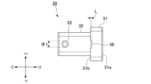
- the first member 30 according to this embodiment has a large diameter portion 31 and a small diameter portion 32 extending rearward from the large diameter portion 31 .
- the large-diameter portion 31 and the small-diameter portion 32 in this embodiment are formed in a substantially rectangular shape in a cross-sectional view perpendicular to the longitudinal direction Z.
- the “substantially rectangular shape” includes a case where it can be regarded as a rectangular shape by eliminating chamfering and manufacturing errors.
- the dimensions of the small diameter portion 32 in the first direction X and the second direction Y are smaller than the dimensions of the large diameter portion 31 in the first direction X and the second direction Y, respectively.
- a through hole 33 is formed in the first member 30 so as to pass through the large-diameter portion 31 and the small-diameter portion 32 in the longitudinal direction Z (see also FIG. 2).
- the first member 30 has a tubular shape.
- the large diameter portion 31 has a pressing surface 31a facing forward and a pressed surface 31b facing rearward.
- a fitting recess 36 recessed forward is formed in the pressed surface 31b.
- the distance in the longitudinal direction Z between the front end of the fitting recess 36 and the pressed surface 31b may be referred to as the "recess amount L of the fitting recess 36" (see FIG. 5).
- the fitting recess 36 in this embodiment is arranged at the central position in the second direction Y of the large diameter portion 31 .
- the first member 30 according to the present embodiment is formed with a pair of locking holes 34 passing through the upper wall and the lower wall of the small diameter portion 32 in the second direction Y, respectively.
- the shape of the locking hole 34 according to this embodiment is rectangular when viewed from the second direction Y. As shown in FIG.
- the first member 30 has a pair of retaining pins 35 projecting outward in the first direction X from the side surface of the small diameter portion 32 .
- Each retainer pin 35 according to the present embodiment is positioned at the rear end of the small diameter portion 32 .
- each retainer pin 35 has a substantially circular shape when viewed from the first direction X.
- the "substantially circular shape" includes an elliptical shape and a case that can be regarded as a circular shape if manufacturing errors are eliminated.
- the outer diameter of the retainer pin 35 may be represented by symbol ⁇ 1.
- the second member 60 according to this embodiment is attached to the proximal end 10b of the ferrule 10. As shown in FIG.
- the second member 60 according to this embodiment functions as a pin clamp.
- the second member 60 according to this embodiment has a gripping base 61 and an extension 62 extending rearward from the gripping base 61 .
- the gripping base portion 61 and the extension portion 62 in this embodiment are each formed in a substantially rectangular shape in a cross-sectional view perpendicular to the longitudinal direction Z.
- the “substantially rectangular shape” includes a case where it can be regarded as a rectangular shape by eliminating chamfering and manufacturing errors.
- the dimensions of the extending portion 62 in the first direction X and the second direction Y are smaller than the dimensions of the gripping base 61 in the first direction X and the second direction Y, respectively.
- the extending portion 62 is inserted through the through hole 33 of the first member 30 (see also FIG. 2).
- the second member 60 is formed with a fiber insertion hole 63 passing through the grip base 61 and the extension 62 in the longitudinal direction Z (see also FIG. 2).
- the second member 60 has a tubular shape.
- a plurality of optical fibers 20 are inserted through the fiber insertion holes 63 .
- the gripping base 61 has a pressing surface 61a facing forward, a biased surface 61b facing rearward, and a pair of first opposing surfaces 61c facing forward.
- the pressing surface 61a abuts on the proximal end 10b of the ferrule 10 via an auxiliary tool 67 (see FIG. 3).
- the pressing surface 61a is positioned between the pair of first opposing surfaces 61c. Further, each first opposing surface 61c is located behind the pressing surface 61a.
- An opening 64 and a locking claw 65 are formed in each of the upper wall and the lower wall of the extending portion 62 according to this embodiment.
- the shape of the opening 64 according to the present embodiment is a C shape that opens rearward when viewed from the second direction Y.
- the locking claw 65 is surrounded by an opening 64 when viewed from the second direction Y.
- the locking claw 65 is elastically bendable in the second direction Y with the rear end portion of the locking claw 65 as a base end.
- a locking protrusion 65 a that protrudes outward in the second direction Y is provided at the front end (tip) of each locking claw 65 .
- the biasing member 40 is arranged between the first member 30 and the ferrule 10 in the longitudinal direction Z. More specifically, in the present embodiment, the biasing member 40 is sandwiched between the pressing surface 31a of the first member 30 and the biased surface 61b of the second member 60 in the longitudinal direction Z. As shown in FIG. The biasing member 40 is compressed between the pressing surface 31a and the biased surface 61b, so that the ferrule 10 is directed toward the connection end 10a (forward) via the pressing surface 61a of the second member 60. ) have a biasing role.
- a coil spring for example, can be used as the biasing member 40 .
- each locking protrusion 65a is inserted into the locking hole 34 and 34 (see also FIGS. 9A and 9B).
- the second member 60 holds the first member 30 in a state in which the first member 30 presses the biasing member 40 and the biasing member 40 is compressed. That is, the first member 30 functions as a holding member that causes the second member 60 to hold the biasing member 40 .
- the second member 60 is a so-called pin clamp, and is formed with a pair of guide pin gripping holes 66 for gripping a pair of guide pins 70 .
- Each guide pin gripping hole 66 opens onto the pressing surface 61 a of the gripping base 61 .
- the guide pin gripping hole 66 according to this embodiment opens inward in the first direction X and communicates with the fiber insertion hole 63 .
- an auxiliary tool 67 is attached to the pressing surface 61a of the gripping base 61 according to this embodiment.
- a pair of slits 67a extending in the second direction Y are formed in the auxiliary tool 67 .
- Each guide pin 70 is gripped by the second member 60 by being passed through the slit 67 a and inserted into the guide pin gripping hole 66 .
- the guide pin gripping hole 66 may not communicate with the fiber insertion hole 63 and may open only on the pressing surface 61a. In this case, the auxiliary tool 67 may not be attached to the grip base 61 . Further, if the first member 30 can be held while the first member 30 presses the biasing member 40, the second member 60 may not be a pin clamp.
- the spring push 50 according to this embodiment is arranged behind the first member 30 .
- the spring push 50 according to this embodiment has a rotation base 51, a pressing projection 52, a spindle projection 53, a fixed projection 54, an auxiliary projection 55, and a handle 56.
- the handle 56 extends rearward from the rotation base 51 .
- the spindle projection 53 is a projection that projects downward from the rotation base 51 . As shown in FIG. 2 , the spindle projection 53 is inserted into a spindle hole 83 formed in the adapter 2 . Although the details will be described later, by inserting the support shaft projection 53 into the support shaft hole 83, the spring push 50 can perform rotational movement using the support shaft projection 53 as a spindle (see also FIG. 10A).
- the pressing protrusion 52 is a protrusion that protrudes forward from the rotation base 51. As shown in FIG. As shown in FIG. 3 , the pressing protrusion 52 is fitted into the fitting recess 36 of the first member 30 . As the spring push 50 performs the rotational motion described above, the pressing projection 52 presses the first member 30 forward (see also FIG. 10A). In other words, the spring push 50 presses the first member 30 forward by rotational motion.
- the fixed projection 54 is a projection formed on the handle 56.
- the fixing protrusion 54 is inserted into a fixing hole 84 formed in the adapter 2.
- the spring push 50 is fixed to the adapter 2 while pressing the first member 30 (see also FIG. 10B).
- the spring push 50 is formed with a pair of retaining holes 51a penetrating through the rotation base 51 in the first direction X.
- the retainer pin 35 of the first member 30 is inserted into each retainer hole 51a.
- the shape of each retaining hole 51a according to the present embodiment is substantially circular when viewed from the first direction X.
- the “substantially circular shape” also includes cases where the shape can be regarded as circular if manufacturing errors are eliminated.
- the inner diameter of the retainer hole 51a may be denoted by ⁇ 2.
- the inner diameter ⁇ 2 of the retaining hole 51 a is equal to or greater than the outer diameter ⁇ 1 of the retaining pin 35 .
- the recess amount L (see FIG. 5) of the fitting recess 36 is larger than the difference between the inner diameter ⁇ 2 of the retaining hole 51a and the outer diameter ⁇ 1 of the retaining pin 35 .
- This configuration prevents the pressing projection 52 from falling out of the fitting recess 36 . That is, the first member 30 also functions as a holding member that holds the spring push 50 .
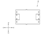
- the adapter 2 has an adapter body portion 80, a plurality of insertion openings 81, and a non-insertion portion .
- the insertion port 81 is a hole formed in the adapter main body 80, into which the multi-fiber optical connector 1 (male connector 1M or female connector 1F) described above is inserted.
- the non-insertion portion 82 is a portion of the adapter body portion 80 where the insertion opening 81 is not formed.
- the adapter main body 80 has four male insertion openings 81M into which the male connectors 1M are respectively inserted, four female insertion openings 81F into which the female connectors 1F are inserted, is formed.
- the four male insertion openings 81M and the four female insertion openings 81F are in one-to-one correspondence and are opposed to each other in the longitudinal direction Z.
- the structure of the male insertion port 81M and the structure of the female insertion port 81F are basically the same. Henceforth, when describing the insertion port 81, unless otherwise specified, the male insertion port 81M will be described.
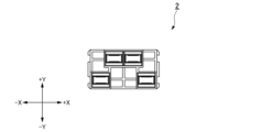
- each of the four male insertion openings 81M may be referred to as a first insertion opening 81A, a second insertion opening 81B, a third insertion opening 81C, and a fourth insertion opening 81D. (See FIG. 7F).
- the four insertion openings 81A to 81D according to this embodiment are arranged symmetrically in the first direction X (see FIG. 7F).
- each insertion port 81 has a small diameter portion 81a into which the ferrule 10 is inserted, and a large diameter portion 81b which is a hole communicating with the rear end of the small diameter portion 81a.
- the dimensions of the large diameter portion 81b in the first direction X and the second direction Y are larger than the dimensions of the small diameter portion 81a in the first direction X and the second direction Y, respectively.
- a rearward facing second facing surface 81c is provided at the front end of the large diameter portion 81b.
- Each insertion port 81 is formed with the previously described support shaft hole 83 and fixing hole 84 .
- the spindle hole 83 according to this embodiment is a hole that opens to the lower surface of the insertion port 81 .
- the shape of the insertion opening 81 corresponds to the shape of the spindle projection 53 .
- the fixing hole 84 according to this embodiment is a hole that opens to the upper surface of the insertion port 81 .
- the shape of the fixing hole 84 corresponds to the shape of the fixing projection 54 .
- the first insertion opening 81A and the second insertion opening 81B are arranged side by side in the first direction X.
- the third insertion opening 81C and the fourth insertion opening 81D are arranged side by side in the first direction X.
- the positions of the third insertion opening 81C and the fourth insertion opening 81D are different in the second direction Y from the positions of the first insertion opening 81A and the second insertion opening 81B.
- the third insertion opening 81C and the fourth insertion opening 81D are positioned below the first insertion opening 81A and the second insertion opening 81B.
- the third insertion opening 81C and the fourth insertion opening 81D are arranged outside in the first direction X as viewed from the longitudinal direction Z relative to the first insertion opening 81A and the second insertion opening 81B.
- the distance d2 between the third insertion opening 81C and the fourth insertion opening 81D in the first direction X is greater than the distance d1 between the first insertion opening 81A and the second insertion opening 81B in the first direction X. is also big.
- the first members 30 of the four multi-fiber optical connectors 1 may not overlap each other in the second direction Y.
- the positions of the four insertion openings 81A to 81D are set so that the four first members 30 do not overlap each other in the second direction Y in the inserted state.
- the non-insertion portion 82 of the adapter body portion 80 may have a mesh structure. That is, the non-insertion portion 82 may include a plurality of through-holes 82a passing through the adapter body portion 80 in the longitudinal direction Z, and a plurality of column beam portions 82b arranged in the through-holes 82a. Each column beam part 82b which concerns on this embodiment is extended in the 1st direction X or the 2nd direction Y, and connects the inner surface of the through-hole 82a. Since the non-insertion portion 82 has the through hole 82a, the air permeability of the optical connection structure 100 is improved. In other words, the optical connection structure 100 is less likely to block the flow of heat in the optical connection device. Moreover, the mechanical strength of the adapter 2 can be improved by arranging the plurality of column beam portions 82b in the through hole 82a. Note that the number, orientation, and shape of the column beam portions 82b can be changed as appropriate.
- an assembly step of assembling the multi-fiber optical connector 1 an insertion step of inserting the assembled multi-fiber optical connector 1 into the insertion port 81 of the adapter 2 is done.
- the assembly process may be performed, for example, at a factory that manufactures the multi-fiber optical connector 1 .
- the insertion process may be performed by a user using the optical connection structure 100, for example.
- the assembling process includes a sandwiching process of sandwiching the biasing member 40 between the first member 30 and the second member 60 . More specifically, first, the extending portion 62 of the second member 60 is inserted into the biasing member 40, and the front end of the biasing member 40 contacts the biased surface 61b of the second member 60 (see FIG. 9A). ). Next, the first member 30 is attached to the second member 60 from the rear such that the extending portion 62 is inserted into the through hole 33 of the first member 30 . When the first member 30 advances, as shown in FIG. 9A, the locking claw 65 bends inward in the second direction Y, and the pressing surface 31a of the first member 30 comes into contact with the rear end of the biasing member 40. As shown in FIG.
- a ferrule attaching step of attaching the ferrule 10 to the second member 60 a spring push attaching step of attaching the spring push 50 to the first member 30, the ferrule 10, the first member 30, the spring push 50,
- the assembling process is completed by performing a step of inserting the optical fiber 20 through the second member 60 and the like.
- the order in which the sandwiching process, the ferrule mounting process, the spring push mounting process, and the insertion process are performed can be changed as appropriate.
- the user first inserts the pivot projection 53 of the spring push 50 into the pivot hole 83 of the adapter 2 as shown in FIG. 10A.
- the user for example, grips and lifts the handle 56 to rotate the spring push 50 around the spindle projection 53 (see FIG. 10B). More specifically, when the user lifts the handle 56, the spring push 50 rotates with the rotation axis parallel to the first direction X. As shown in FIG. At this time, the pressing protrusion 52 of the spring push 50 and the fitting recess 36 of the first member 30 slide against each other, and the pressing protrusion 52 presses the first member 30 forward. That is, the rotational motion of the spring push 50 is converted into linear motion of the first member 30 in the longitudinal direction Z.
- the spring push 50 pushes the first member 30 forward, the biasing member 40 is further compressed than when the assembly process is completed.
- the fixing protrusion 54 of the spring push 50 is inserted into the fixing hole 84 of the adapter 2 .
- the spring push 50 and the multi-fiber optical connector 1 are fixed in the insertion opening 81 of the adapter 2 while the spring push 50 presses the first member 30 .
- the manufacture (assembly) of the optical connection structure 100 that is, the connection between each male connector 1M and the female connector 1F is completed.
- the rotational movement of the spring push 50 is used to press the first member 30 . Therefore, the principle of leverage can reduce the force to be applied to the spring push 50 when the user connects the multi-fiber optical connectors 1 to each other.
- the biasing member 40 can be compressed in two steps, ie, the assembly step (sandwiching step) and the insertion step. Therefore, it is possible to reduce the amount by which the user should rotate the spring push 50 during the insertion process.
- the multi-fiber optical connector 1 has a structure in which the spring push 50 presses the biasing member 40 via the first member 30 . More specifically, a structure is employed that presses the biasing member 40 by converting the rotational motion of the spring push 50 into the linear motion of the first member 30 . With this configuration, buckling of the biasing member 40 is less likely to occur than when the spring push 50 in rotational motion directly contacts the biasing member 40 .
- the biasing member 40 is arranged outside the extending portion 62 of the second member 60, so contact between the biasing member 40 and the optical fiber 20 is suppressed. be done. This prevents the biasing member 40 from accidentally contacting the optical fiber 20 and damaging the optical fiber 20 during the insertion process.
- the third insertion opening 81C and the fourth insertion opening 81D according to the present embodiment are arranged outside in the first direction X relative to the first insertion opening 81A and the second insertion opening 81B. there is Therefore, the user can easily operate the spring push 50 by touching the spring push 50 by inserting a finger into the space S1 (see FIG. 11) between the third insertion opening 81C and the fourth insertion opening 81D. (rotate). Further, as shown in FIG. 11, even when the optical connection structure 100 according to the present embodiment is two-dimensionally integrated in the first direction X and the second direction Y, the user can easily operate the spring push 50. be able to.
- the user can operate the spring push 50 by inserting a finger into the space S1 described above or the space S2 shown in FIG.
- the space S2 is a space between the second insertion opening 81B of a given optical connection structure 100 and the first insertion opening 81A of the adjacent optical connection structure 100 (see FIG. 11). reference).
- the multi-fiber optical connector 1 is the multi-fiber optical connector 1 to be inserted into the adapter 2, and the connection end 10a provided with the connection end surface 11 and the connection end 10a are A ferrule 10 having a base end 10b located on the opposite side and a plurality of fiber holes 12 through which a plurality of optical fibers 20 can be inserted toward a connection end face 11, and opposed to the base end 10b of the ferrule 10 in the longitudinal direction Z. and a biasing member 40 disposed between the first member 30 and the ferrule 10 in the longitudinal direction Z to bias the ferrule 10 forward (connection end 10a). , and a spring push 50 that presses the first member 30 forward (connecting end 10a) by rotational motion.
- the multi-fiber optical connector 1 further includes a second member 60 that holds the first member 30 while the first member 30 presses the biasing member 40 .
- a retaining pin 35 is formed in the first member 30, and a retaining hole 51a is formed in the spring push 50.
- the spring push 50 is secured to the first member. It is held by one member 30 . This configuration can prevent the spring push 50 from coming off the first member 30 .
- the spring push 50 has a pressing projection 52 that contacts the first member 30 and presses the first member 30, and the first member 30 is formed with a fitting recess 36 into which the pressing projection 52 is fitted.
- the recess amount L of the fitting recess 36 is larger than the difference between the inner diameter ⁇ 2 of the retaining hole 51 a and the outer diameter ⁇ 1 of the retaining pin 35 . This configuration prevents the pressing projection 52 from falling out of the fitting recess 36 .
- the spring push 50 has a support shaft projection 53, which is a projection that is inserted into a support shaft hole 83, which is a hole formed in the adapter 2, and serves as a support shaft for the rotational movement. This configuration allows the spring push 50 to rotate stably.
- the spring push 50 has a fixing projection 54 , and the fixing projection 54 is inserted into a fixing hole 84 that is a hole formed in the adapter 2 to press the spring push 50 against the first member 30 . It is a projection for fixing 50 to the adapter 2 .
- the optical connection structure 100 includes at least four multi-fiber optical connectors 1 and an adapter 2 formed with at least four insertion openings 81 into which the multi-fiber optical connectors 1 are inserted,
- the first insertion opening 81A and the second insertion opening 81B are arranged side by side in the first direction X, and the positions of the third insertion opening 81C and the fourth insertion opening 81D are the same in the second direction Y as the first insertion opening 81A.
- the second insertion opening 81B, the third insertion opening 81C and the fourth insertion opening 81D are located outside the first insertion opening 81A and the second insertion opening 81B in the first direction X when viewed from the longitudinal direction Z. are placed out of alignment.
- the user can easily operate the spring push 50 by inserting a finger into the space S1 between the third insertion opening 81C and the fourth insertion opening 81D.
- the first members 30 of the four multi-fiber optical connectors 1 do not overlap each other in the second direction Y when the four multi-fiber optical connectors 1 are inserted into the four insertion openings 81A to 81D. According to this configuration, the above-described space S1 becomes larger, and the operation of the spring push 50 becomes easier.
- the support shaft projection 53 of the spring push 50 protrudes downward from the rotation base 51, but may protrude upward from the rotation base 51.
- the rotation axis of the rotational movement of the spring push 50 may not be parallel to the first direction X, but may be parallel to another direction perpendicular to the longitudinal direction Z (eg, the second direction Y).
- the direction in which the support shaft protrusion 53 protrudes from the rotation base 51, the protrusion direction of the retainer pin 35, and the penetration direction of the retainer hole 51a may be changed according to the direction of the rotational movement.
- the spring push 50 can be fixed to the adapter 2, the position and orientation of the fixing projection 54 can be changed as appropriate.
- the retaining pin 35 is formed in the first member 30 and the retaining hole 51a is formed in the spring push 50.
- the retaining pin 35 is formed in the spring push 50 and the retaining hole 51a is formed. may be formed on the first member 30 .
- the multi-fiber optical connector 1 does not have to include the second member 60 .
- a configuration may be adopted in which the front end of the biasing member 40 contacts the proximal end 10b of the ferrule 10 and the biasing member 40 directly biases the ferrule 10 .
- the number of insertion openings 81 (male insertion openings 81M) provided in the adapter 2 can be appropriately changed as long as it is four or more.
- Optical connection structure 1... Multi-core optical connector 2... Adapter 10... Ferrule 10a... Connection end 10b... Base end 11... Connection end surface 12... Fiber hole 20... Optical fiber 30... First member 34... Locking hole 35... Removal Stop pin 36... Fitting recess 40... Biasing member 50... Spring push 51a... Retaining hole 52... Pressing protrusion 53... Support shaft protrusion 54... Fixed protrusion 81... Insertion opening 81A... First insertion opening 81B... Second insertion opening 81C...Third insertion port 81D...Fourth insertion port 83...Support shaft hole 84...Fixing hole Z...Longitudinal direction X...First direction Y...Second direction
Landscapes
- Physics & Mathematics (AREA)
- General Physics & Mathematics (AREA)
- Optics & Photonics (AREA)
- Mechanical Coupling Of Light Guides (AREA)
Priority Applications (4)
| Application Number | Priority Date | Filing Date | Title |
|---|---|---|---|
| US18/834,422 US20250155650A1 (en) | 2022-02-17 | 2022-08-22 | Multi-fiber optical connector and optical connection structure |
| CN202280087156.0A CN118475862A (zh) | 2022-02-17 | 2022-08-22 | 多芯光连接器及光连接构造 |
| JP2024500933A JP7812908B2 (ja) | 2022-02-17 | 2022-08-22 | 多心光コネクタおよび光接続構造 |
| IL314503A IL314503A (en) | 2022-02-17 | 2022-08-22 | Multiple optical fiber connector and optical connection structure |
Applications Claiming Priority (2)
| Application Number | Priority Date | Filing Date | Title |
|---|---|---|---|
| JP2022-022852 | 2022-02-17 | ||
| JP2022022852 | 2022-02-17 |
Publications (1)
| Publication Number | Publication Date |
|---|---|
| WO2023157348A1 true WO2023157348A1 (ja) | 2023-08-24 |
Family
ID=87578226
Family Applications (1)
| Application Number | Title | Priority Date | Filing Date |
|---|---|---|---|
| PCT/JP2022/031536 Ceased WO2023157348A1 (ja) | 2022-02-17 | 2022-08-22 | 多心光コネクタおよび光接続構造 |
Country Status (5)
| Country | Link |
|---|---|
| US (1) | US20250155650A1 (https=) |
| JP (1) | JP7812908B2 (https=) |
| CN (1) | CN118475862A (https=) |
| IL (1) | IL314503A (https=) |
| WO (1) | WO2023157348A1 (https=) |
Citations (7)
| Publication number | Priority date | Publication date | Assignee | Title |
|---|---|---|---|---|
| JPH0581808U (ja) * | 1992-04-02 | 1993-11-05 | 三和電気工業株式会社 | Sc形多芯光コネクタ |
| JP2013532849A (ja) * | 2010-07-30 | 2013-08-19 | コーニング ケーブル システムズ リミテッド ライアビリティ カンパニー | 相補嵌合ジオメトリを備えたフェルール及び関連光ファイバコネクタ |
| JP2017090798A (ja) * | 2015-11-16 | 2017-05-25 | 株式会社フジクラ | 光コネクタ |
| US20170343741A1 (en) * | 2014-12-19 | 2017-11-30 | Adc Telecommunications (Shanghai) Distribution Co., Ltd. | Hardened fiber optic connector with pre-compressed spring |
| WO2019230504A1 (ja) * | 2018-05-28 | 2019-12-05 | 日本通信電材株式会社 | 弾性部材及び光コネクタ |
| CN111200212A (zh) * | 2018-11-16 | 2020-05-26 | 康普技术有限责任公司 | 连接固定装置 |
| JP2020204701A (ja) * | 2019-06-17 | 2020-12-24 | 株式会社フジクラ | 光コネクタ |
Family Cites Families (2)
| Publication number | Priority date | Publication date | Assignee | Title |
|---|---|---|---|---|
| JP5687965B2 (ja) * | 2011-07-05 | 2015-03-25 | 株式会社フジクラ | 光コネクタ、コネクタ接続ユニット |
| JP2019113719A (ja) * | 2017-12-25 | 2019-07-11 | 株式会社フジクラ | 光コネクタ |
-
2022
- 2022-08-22 IL IL314503A patent/IL314503A/en unknown
- 2022-08-22 CN CN202280087156.0A patent/CN118475862A/zh active Pending
- 2022-08-22 US US18/834,422 patent/US20250155650A1/en active Pending
- 2022-08-22 WO PCT/JP2022/031536 patent/WO2023157348A1/ja not_active Ceased
- 2022-08-22 JP JP2024500933A patent/JP7812908B2/ja active Active
Patent Citations (7)
| Publication number | Priority date | Publication date | Assignee | Title |
|---|---|---|---|---|
| JPH0581808U (ja) * | 1992-04-02 | 1993-11-05 | 三和電気工業株式会社 | Sc形多芯光コネクタ |
| JP2013532849A (ja) * | 2010-07-30 | 2013-08-19 | コーニング ケーブル システムズ リミテッド ライアビリティ カンパニー | 相補嵌合ジオメトリを備えたフェルール及び関連光ファイバコネクタ |
| US20170343741A1 (en) * | 2014-12-19 | 2017-11-30 | Adc Telecommunications (Shanghai) Distribution Co., Ltd. | Hardened fiber optic connector with pre-compressed spring |
| JP2017090798A (ja) * | 2015-11-16 | 2017-05-25 | 株式会社フジクラ | 光コネクタ |
| WO2019230504A1 (ja) * | 2018-05-28 | 2019-12-05 | 日本通信電材株式会社 | 弾性部材及び光コネクタ |
| CN111200212A (zh) * | 2018-11-16 | 2020-05-26 | 康普技术有限责任公司 | 连接固定装置 |
| JP2020204701A (ja) * | 2019-06-17 | 2020-12-24 | 株式会社フジクラ | 光コネクタ |
Also Published As
| Publication number | Publication date |
|---|---|
| US20250155650A1 (en) | 2025-05-15 |
| IL314503A (en) | 2024-09-01 |
| CN118475862A (zh) | 2024-08-09 |
| JP7812908B2 (ja) | 2026-02-10 |
| JPWO2023157348A1 (https=) | 2023-08-24 |
Similar Documents
| Publication | Publication Date | Title |
|---|---|---|
| US8376629B2 (en) | Fiber optic connector assembly employing fiber movement support and method of assembly | |
| JP4951029B2 (ja) | 光コネクタアダプタ及び光コネクタ | |
| JP7606008B2 (ja) | フェルールの保持構造 | |
| JP2020046582A (ja) | Lc用ユニブーツプラグコネクタ | |
| JP4409364B2 (ja) | コネクタホルダおよびコネクタホルダ付き光コネクタ | |
| WO2023157348A1 (ja) | 多心光コネクタおよび光接続構造 | |
| JP7457204B2 (ja) | 光コネクタの製造工具 | |
| JP2005077846A (ja) | 光コネクタ | |
| JP7778925B2 (ja) | 光コネクタ、光コネクタアセンブリ、および光接続構造 | |
| JP2007240943A (ja) | 光コネクタ | |
| JP4387732B2 (ja) | 光コネクタ | |
| JP4339023B2 (ja) | 光コネクタ、コネクタホルダ | |
| JP2005062513A (ja) | 光コネクタ | |
| JP4043021B2 (ja) | 光コネクタ組立工具および光ファイバ接続方法 | |
| JP4361465B2 (ja) | 光コネクタ用工具、工具付き光コネクタ | |
| JP2007219012A (ja) | 光コネクタ装置 | |
| JP4441480B2 (ja) | 光コネクタ用接続治具 | |
| JP2011081038A (ja) | 光ファイバ接続方法 | |
| JP2005128327A (ja) | 光コネクタ | |
| JP2012118221A (ja) | 光コネクタおよびケーブル付き光コネクタの製造方法 | |
| US7416348B2 (en) | Optical connector excellent in assemblability and dimensional accuracy | |
| CN117289402A (zh) | 光连接器 | |
| JP2007121862A (ja) | 光コネクタ用工具、工具付き光コネクタ | |
| JPWO2023157348A5 (https=) | ||
| CN121578452A (zh) | 一种超小型光纤连接器 |
Legal Events
| Date | Code | Title | Description |
|---|---|---|---|
| 121 | Ep: the epo has been informed by wipo that ep was designated in this application |
Ref document number: 22927242 Country of ref document: EP Kind code of ref document: A1 |
|
| WWE | Wipo information: entry into national phase |
Ref document number: 202280087156.0 Country of ref document: CN |
|
| ENP | Entry into the national phase |
Ref document number: 2024500933 Country of ref document: JP Kind code of ref document: A |
|
| WWE | Wipo information: entry into national phase |
Ref document number: 314503 Country of ref document: IL |
|
| WWE | Wipo information: entry into national phase |
Ref document number: 18834422 Country of ref document: US |
|
| NENP | Non-entry into the national phase |
Ref country code: DE |
|
| 122 | Ep: pct application non-entry in european phase |
Ref document number: 22927242 Country of ref document: EP Kind code of ref document: A1 |
|
| WWP | Wipo information: published in national office |
Ref document number: 18834422 Country of ref document: US |