WO2023157244A1 - 加工時間予測装置及び加工時間予測方法 - Google Patents
加工時間予測装置及び加工時間予測方法 Download PDFInfo
- Publication number
- WO2023157244A1 WO2023157244A1 PCT/JP2022/006693 JP2022006693W WO2023157244A1 WO 2023157244 A1 WO2023157244 A1 WO 2023157244A1 JP 2022006693 W JP2022006693 W JP 2022006693W WO 2023157244 A1 WO2023157244 A1 WO 2023157244A1
- Authority
- WO
- WIPO (PCT)
- Prior art keywords
- axis
- machining
- unit
- machining time
- time prediction
- Prior art date
- Legal status (The legal status is an assumption and is not a legal conclusion. Google has not performed a legal analysis and makes no representation as to the accuracy of the status listed.)
- Ceased
Links
Images






Classifications
-
- G—PHYSICS
- G05—CONTROLLING; REGULATING
- G05B—CONTROL OR REGULATING SYSTEMS IN GENERAL; FUNCTIONAL ELEMENTS OF SUCH SYSTEMS; MONITORING OR TESTING ARRANGEMENTS FOR SUCH SYSTEMS OR ELEMENTS
- G05B19/00—Program-control systems
- G05B19/02—Program-control systems electric
- G05B19/18—Numerical control [NC], i.e. automatically operating machines, in particular machine tools, e.g. in a manufacturing environment, so as to execute positioning, movement or co-ordinated operations by means of program data in numerical form
- G05B19/406—Numerical control [NC], i.e. automatically operating machines, in particular machine tools, e.g. in a manufacturing environment, so as to execute positioning, movement or co-ordinated operations by means of program data in numerical form characterised by monitoring or safety
- G05B19/4063—Monitoring general control system
-
- G—PHYSICS
- G05—CONTROLLING; REGULATING
- G05B—CONTROL OR REGULATING SYSTEMS IN GENERAL; FUNCTIONAL ELEMENTS OF SUCH SYSTEMS; MONITORING OR TESTING ARRANGEMENTS FOR SUCH SYSTEMS OR ELEMENTS
- G05B19/00—Program-control systems
- G05B19/02—Program-control systems electric
- G05B19/18—Numerical control [NC], i.e. automatically operating machines, in particular machine tools, e.g. in a manufacturing environment, so as to execute positioning, movement or co-ordinated operations by means of program data in numerical form
- G05B19/406—Numerical control [NC], i.e. automatically operating machines, in particular machine tools, e.g. in a manufacturing environment, so as to execute positioning, movement or co-ordinated operations by means of program data in numerical form characterised by monitoring or safety
- G05B19/4069—Simulating machining process on screen
-
- G—PHYSICS
- G05—CONTROLLING; REGULATING
- G05B—CONTROL OR REGULATING SYSTEMS IN GENERAL; FUNCTIONAL ELEMENTS OF SUCH SYSTEMS; MONITORING OR TESTING ARRANGEMENTS FOR SUCH SYSTEMS OR ELEMENTS
- G05B19/00—Program-control systems
- G05B19/02—Program-control systems electric
- G05B19/18—Numerical control [NC], i.e. automatically operating machines, in particular machine tools, e.g. in a manufacturing environment, so as to execute positioning, movement or co-ordinated operations by means of program data in numerical form
- G05B19/416—Numerical control [NC], i.e. automatically operating machines, in particular machine tools, e.g. in a manufacturing environment, so as to execute positioning, movement or co-ordinated operations by means of program data in numerical form characterised by control of velocity, acceleration or deceleration
-
- G—PHYSICS
- G05—CONTROLLING; REGULATING
- G05B—CONTROL OR REGULATING SYSTEMS IN GENERAL; FUNCTIONAL ELEMENTS OF SUCH SYSTEMS; MONITORING OR TESTING ARRANGEMENTS FOR SUCH SYSTEMS OR ELEMENTS
- G05B19/00—Program-control systems
- G05B19/02—Program-control systems electric
- G05B19/18—Numerical control [NC], i.e. automatically operating machines, in particular machine tools, e.g. in a manufacturing environment, so as to execute positioning, movement or co-ordinated operations by means of program data in numerical form
- G05B19/414—Structure of the control system, e.g. common controller or multiprocessor systems, interface to servo, programmable interface controller
- G05B19/4145—Structure of the control system, e.g. common controller or multiprocessor systems, interface to servo, programmable interface controller characterised by using same processor to execute programmable controller and numerical controller function [CNC] and PC controlled NC [PCNC]
-
- G—PHYSICS
- G05—CONTROLLING; REGULATING
- G05B—CONTROL OR REGULATING SYSTEMS IN GENERAL; FUNCTIONAL ELEMENTS OF SUCH SYSTEMS; MONITORING OR TESTING ARRANGEMENTS FOR SUCH SYSTEMS OR ELEMENTS
- G05B2219/00—Program-control systems
- G05B2219/30—Nc systems
- G05B2219/32—Operator till task planning
- G05B2219/32063—Adapt speed of tool as function of deviation from target rate of workpieces
-
- G—PHYSICS
- G05—CONTROLLING; REGULATING
- G05B—CONTROL OR REGULATING SYSTEMS IN GENERAL; FUNCTIONAL ELEMENTS OF SUCH SYSTEMS; MONITORING OR TESTING ARRANGEMENTS FOR SUCH SYSTEMS OR ELEMENTS
- G05B2219/00—Program-control systems
- G05B2219/30—Nc systems
- G05B2219/33—Director till display
- G05B2219/33099—Computer numerical control [CNC]; Software control [SWC]
-
- G—PHYSICS
- G05—CONTROLLING; REGULATING
- G05B—CONTROL OR REGULATING SYSTEMS IN GENERAL; FUNCTIONAL ELEMENTS OF SUCH SYSTEMS; MONITORING OR TESTING ARRANGEMENTS FOR SUCH SYSTEMS OR ELEMENTS
- G05B2219/00—Program-control systems
- G05B2219/30—Nc systems
- G05B2219/37—Measurements
- G05B2219/37336—Cutting, machining time
Definitions
- the present invention relates to a machining time prediction device and a machining time prediction method for a machine tool, and more particularly to a machining time prediction device and a machining time prediction method for predicting the machining time of a machine tool that controls at least one axis to machine a workpiece based on a machining program.
- the present invention relates to a machining time prediction method.
- Patent Literature 1 describes a numerical control device that obtains the shortest predicted machining time within an allowable machining error. Specifically, in Patent Document 1, speed data that gives a machining speed and accuracy data that gives a machining accuracy when machining a workpiece are specified, and a program analysis unit creates interpolation data for a machining program, The interpolating section performs interpolation according to the interpolation data based on the velocity created by the pre-interpolation acceleration/deceleration section to create interpolation data ( ⁇ Pn), and the post-interpolation acceleration/deceleration section performs interpolation on the interpolation data ( ⁇ Pn) after interpolation. It describes that acceleration/deceleration is performed to create servo position command data (VCn).
- VCn servo position command data
- a servo simulation unit receives servo position command data (VCn), creates servo position data (Qn) by simulating an actual servo operation, and a machining time prediction unit predicts the number of times of interpolation based on the interpolation data. It is described that the machining time can be measured by counting , and that the machining error prediction unit obtains the predicted machining error using interpolation data ( ⁇ Pn) and servo position data (Qn).
- Patent Literature 2 describes a numerical control device capable of highly accurate prediction of machining time in consideration of machine delays that occur in machines.
- a numerical controller includes a reference machining time prediction unit that predicts a reference machining time, which is a machining time that does not consider acceleration/deceleration of an axis, based on a machining program, and Acceleration/deceleration number prediction unit that predicts the number of acceleration/deceleration times of the axis during machining, and deviation time that is the difference between the actual machining time that is the actual machining time required for actual machining by the machine and the reference machining time that is predicted for the machining.
- a correction time for correcting the reference machining time based on a data storage unit that stores such information, the number of acceleration/deceleration times predicted by the acceleration/deceleration number prediction unit, and information related to the divergence time stored in the data storage unit. and a machining time prediction unit for calculating a predicted machining time obtained by correcting the reference machining time with the correction time.
- Patent Literature 3 describes a machining time calculation device that can accurately calculate the required machining time before machining.
- a divided trajectory calculation means divides a designated tool trajectory at large intervals in a portion where the curvature is small, and divides the designated tool trajectory at smaller intervals as the curvature increases to obtain divided trajectories.
- the axis control data calculating means moves the tool on each divided locus at a speed according to the specified tool moving speed to machine the workpiece, each position obtained at an arbitrary position on the divided locus and at a predetermined time interval It is described that the axial control data A is obtained from the time change of the tool moving speed in the axial direction.
- Patent Literature 3 describes that the required machining time calculation means calculates the machining time for machining the specified range.
- a representative first aspect of the present disclosure is a machining time prediction device that predicts the machining time of a machine tool that controls at least one axis to machine a workpiece based on a machining program, an analysis unit that analyzes the machining program and generates an operation command for the axis; an execution control unit comprising an interpolation unit that supervises the execution of the operation command and instructs the operation of the axis from the result of analyzing the machining program, and an operation completion determination unit that determines that the operation of the axis is completed; , an axis control unit that generates a control command based on the operation instruction of the axis from the interpolation unit; a machining time prediction unit that measures the time required to execute the machining program and predicts the machining time; an axis operation simulation unit that simulates the operation of the axis based on the control command and outputs a virtual result; with The motion completion determination unit determines completion of the motion of the axis based on the virtual performance. It is a machining
- a representative second aspect of the present disclosure is a computer as a machining time prediction device that predicts the machining time of a machine tool that controls at least one axis to machine a workpiece based on a machining program, a process of analyzing the machining program and generating an operation command for the axis; supervising the execution of the motion commands, instructing the motion of the axes based on the result of analyzing the machining program; a process of determining that the movement of the axis is complete; a process of generating a control command based on the operation instruction of the axis; a process of measuring the time required to execute the machining program and estimating the machining time; Axis operation simulation processing for simulating the operation of the axis and outputting a virtual result based on the control command; and run determining completion of the axis operation based on the virtual performance in the process of determining the completion of the axis operation; This is a machining time prediction method.
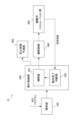
- FIG. 1 is a block diagram showing the configuration of a machining time prediction device according to a first embodiment of the present disclosure
- FIG. FIG. 4 is a block diagram of a transfer function of the shaft motion simulation unit when the shaft of the shaft motion simulation unit is a feed shaft
- FIG. 4 is a block diagram of a transfer function of the shaft motion simulation unit when the shaft of the shaft motion simulation unit is the main shaft
- FIG. 4 is a block diagram showing the configuration of the shaft motion simulation unit when the shaft of the shaft motion simulation unit is the main shaft
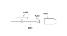
- It is a figure which shows the drive system which consists of a motor, a coupling, and a ball screw.
- FIG. 4 is a characteristic diagram showing the relationship between friction torque and angular velocity of a motor
- 1 is a configuration diagram showing a configuration of a machining center for machining turbine blades W
- FIG. FIG. 4 is a characteristic diagram for explaining an in-position check
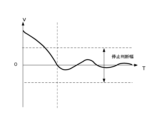
- FIG. 10 is a characteristic diagram for explaining a speed stop determination width
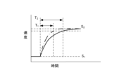
- FIG. 4 is a characteristic diagram for explaining a velocity arrival width and a waiting time until the velocity enters the arrival width
- FIG. 5 is a characteristic diagram showing an X-axis command speed, an X-axis speed output from an axis motion simulation unit, and a waiting time
- It is a flowchart which shows the machining time prediction operation
- FIG. 4 is a block diagram showing a configuration in which a Z-axis motion simulation section operates following motion of a spindle motion simulation section;
- FIG. 4 is a diagram showing a configuration example in which an X-axis motion simulation section and a Z-axis motion simulation section are connected to the same DC bus;
- FIG. 4 is a characteristic diagram showing the relationship between the maximum torque and rotation speed of the motor;
- FIG. 10 is a characteristic diagram showing a predicted waiting time and a waiting time in consideration of the NT characteristic assuming that ⁇ max of the region R1 is also applied to the region R2.
- FIG. 1 is a block diagram showing the configuration of a machining time prediction device according to the first embodiment of the present disclosure.
- the machining time prediction device 10 includes an analysis section 100 , an execution control section 200 , an axis control section 300 , an axis operation simulation section 400 and a machining time prediction section 500 .
- the execution control unit 200 has an interpolation unit 201 and an operation completion determination unit 202 .
- the machining time prediction device 10 predicts the machining time (execution time of the machining program) of a machine tool that controls at least one axis to machine a workpiece based on the machining program.
- the analysis unit 100, the interpolation unit 201, and the axis control unit 300 constitute a numerical control device (hereinafter referred to as NC device).
- the operation completion determination section 202 may be provided inside the NC device together with the interpolation section 201, or may be provided outside the NC device.
- the machining time prediction unit 500 may be provided within the NC device. Each part constituting the machining time prediction device 10 will be described below.
- the analysis unit 100 interprets an NC (Numerical Control) program, which is a machining program that defines feed axis positioning and spindle speed control operations, decomposes the NC program into codes and values, and analyzes the movement distance, movement path, and Obtain the command speed (which will be the operation command for the axis).
- NC Genetic Control
- the execution control unit 200 has an interpolation unit 201 and an operation completion determination unit 202 .
- the interpolator 201 supervises the execution of motion commands and instructs the motion of the axes based on the results of analysis of the NC program. Specifically, based on the movement distance, straight line or arc movement path, and command speed obtained by the analysis unit 100, interpolation data (axis operation instruction and ) and outputs interpolation data to the axis control unit 300 .
- the operation completion determination unit 202 determines the completion of the axis operation based on the control command output from the axis control unit 300 or the axis operation simulation unit 400 and the virtual performance output from the axis operation simulation unit 400 .
- the virtual results are, for example, the feed axis position, position deviation, speed or speed deviation, and spindle speed output from the shaft motion simulation unit 400 .
- the operation completion determination unit 202 for example, confirms operation completion for a movement command (positioning) for a feed axis and operation completion for a rotation speed change (speed change) of a main axis based on the virtual results. The details of the operation completion confirmation operation by the operation completion determination unit 202 will be described later.
- the axis control unit 300 generates a control command based on the axis operation instruction from the interpolation unit 201 and outputs it to the axis operation simulation unit 400 . Specifically, the axis control unit 300 generates an acceleration/deceleration profile based on the interpolated data, and further distributes it to each control axis, so that the servo motor serving as the feed axis electric motor and the main shaft serving as the main shaft electric motor are generated. A position command value or a speed command value for each motor control cycle is given to the shaft motion simulation unit 400 .
- the axis operation simulation unit 400 performs servo control for following the position command value or speed command value in driving the electric motor that drives the feed axis and the spindle, and simulates the operation of the machine tool, and provides the virtual results to the operation completion determination unit 202. Output. Further, the axis operation simulation unit 400 outputs control commands such as position command values and speed command values to the operation completion determination unit 202 . The details of the shaft motion simulation by the shaft motion simulation unit 400 will be described later.
- the machining time prediction unit 500 obtains the command time of the machining program using the movement distance, the movement path, the command speed, etc. obtained by the analysis unit 100, and the obtained command time and the axis control unit 300 or the operation completion determination unit 202
- the machining time (execution time of the machining program) is predicted from the control command output from and the waiting time obtained from the notification of completion confirmation from the operation completion determination unit 202 .
- the control command input to the machining time prediction unit 500 may be output from the axis control unit 300 or the axis motion simulation unit 400. The details of the machining time prediction operation by the machining time prediction unit 500 will be described later.
- the waiting time is, for example, deceleration to the position range of the designated width or the range of the stop judgment width judged to stop at speed "0" after the speed command value is set to speed "0" (stop). is the time it takes to reach Further, the waiting time is, for example, the time from when the speed command value is set to the target speed until the speed increases and the target speed reaches the target speed range.
- the machining time prediction unit 500 predicts the machining time by adding the total command time and the total waiting time when the axis acceleration and stop commands are repeated in the machining program.
- the axis motion simulation unit 400 simulates the motion of the feed axis that draws a trajectory based on the machining program and the spindle that rotates the tool or work.
- the axis motion simulation unit 400 is illustrated by the transfer function block diagram of FIG. 2, for example, when the axis is a feed axis.
- a block diagram of a configuration similar to that of FIG. 2 is described in Japanese Patent Application Laid-Open No. 3-110607.
- the transfer function of the shaft motion simulation unit 400 is configured by combining the transfer functions 401 to 407 .
- a transfer function 401 is a position loop transfer function, and Kp indicates a position gain.
- a transfer function 402 is the transfer function of the velocity loop, where k1 is the integral gain and k2 is the proportional gain.
- Transfer functions 403 and 404 are transfer functions of the motor. Kt is the torque constant, and Jm is the motor inertia (moment of inertia).
- a transfer function 405 indicates a ball screw or the like that is a coupling portion between the servomotor and the machine.
- Transfer function 406 is the transfer function of the machine, and J L represents the inertia of the machine.
- Transfer function 407 is the transfer function of the integral element that integrates the velocity of the moving parts of the machine to determine the position of the machine.
- a position loop indicated by transfer function 401 and a velocity loop indicated by transfer function 402 are servo control models, and motors, ball screws, etc. and integral elements indicated by transfer functions 403, 404, 405, 406 and 407 are plant models. .
- the angular velocity of the servomotor can be obtained by the differential equation of Equation 1 (Equation 1 below). A numerical solution using this differential equation is included in the plant model.
- Equation 1 ⁇ is angular velocity
- ⁇ is torque
- Jm motor inertia.
- a feedback signal Pf of the machine position detected by a linear scale or the like is subtracted from the position command Pc output from the axis control unit 300 to obtain a position deviation . is required.
- a feedback value Vf of the motor speed detected by a pulse coder or the like attached to the servomotor is subtracted from this speed command Vc to obtain a speed deviation, and proportional integration is performed to obtain a torque command Tc (current command).
- the servomotor is driven based on Tc, and the position and speed of the servomotor are feedback-controlled in a closed-loop manner.
- the shaft operation simulation unit 400 is configured such that the transfer function 407 integrates the angular velocity of the servomotor to obtain the angle of the servomotor, and the value obtained by converting the angle of the servomotor into the position of the machine is regarded as the position of the machine. good too.
- the shaft motion simulation unit 400 is illustrated by the block diagram of the transfer function in FIG. 3, for example, when the shaft is the main shaft.
- the block diagram shown in FIG. 3 corresponds to the block diagram shown in FIG. 2 with the transfer functions 401, 407 associated with the loop of the machine position feedback signal Pf removed.
- the transfer functions 402, 403, 404 shown in FIG. 3 are the same as the transfer functions 402, 403, 404 shown in FIG.
- the motors represented by transfer functions 403, 404 in FIG. 3 are servo motors or induction motors.
- Transfer function 406 in FIG. 3 is the transfer function of the principal axis.
- the transfer function 405 in FIG. 3 is the connection between the motor and the main shaft. Alternatively, the speed may be increased and transmitted to the main shaft.
- a transfer function 404 of the motor outputs a value Vf obtained by converting the angular velocity of the motor to the rotation speed of the main shaft, and a transfer function 402 of the speed loop performs speed control so that the output Vf of the transfer function 404 matches the main shaft rotation speed command Vc. conduct.
- FIG. 3 functions as a spindle motion simulation section even with a configuration in which the output of the transfer function 406 is Vf. Furthermore, even if transfer functions 405 and 406 are removed in FIG. 3, if Jm is the sum of the motor inertia and the main shaft inertia, it functions as a spindle motion simulation section.
- the shaft motion simulation unit 400 is shown in the block diagram of FIG. 4, for example, when the shaft is the main shaft and the motor is the induction motor.
- a block diagram of a configuration similar to that of FIG. 4 is described in JP-A-2020-5406.
- the block diagram shown in FIG. 4 shows the proximity switch, the rotation speed calculation unit using the number of pulses detected by the proximity switch, and the speed command correction unit shown in the block diagram described in Japanese Patent Application Laid-Open No. 2020-5406. is removed.
- the configuration and operation of the shaft operation simulation unit 400, excluding the proximity switch, the rotation speed calculation unit that uses the number of pulses detected by the proximity switch, and the speed command correction unit, are described in Japanese Patent Application Laid-Open No. 2020-5406. Since the configuration and operation are the same, detailed description is omitted.
- the shaft motion simulation section 400 includes a subtractor 411, a speed control section 412, a current control section 413, a primary frequency control section 414, a slip frequency calculation section 415, a subtractor 416, two-phase and three-phase A conversion unit 417 and an induction motor 418 are provided.
- a subtractor 411 obtains a difference between a speed command value output from the shaft control unit 300 and a rotation speed estimated value output from a subtractor 416, which will be described later, and outputs a speed deviation.
- a speed control unit 412 generates a current command value (torque command value) by performing, for example, PI (proportional, integral) control on the speed deviation obtained by the subtractor 411 .
- a current control unit 413 determines a voltage command value (a d-phase voltage command value and a q-phase voltage command value).
- a primary frequency control unit 414 generates a primary frequency command value based on the current command value (torque command value) generated by the speed control unit 412 .
- the slip frequency calculation unit 415 calculates an estimated slip frequency value based on the current command value (torque command value) generated by the speed control unit 412 .
- a subtractor 416 obtains the difference between the primary frequency command value from the primary frequency control unit 414 and the estimated slip frequency value obtained by the slip frequency calculation unit 415, and outputs it as a rotational speed calculation value of the induction motor 418. do.
- the two-phase-to-three phase conversion unit 417 Based on the primary frequency command value from the primary frequency control unit 414, the two-phase-to-three phase conversion unit 417 converts the d-phase voltage command value and the q-phase voltage command value generated by the current control unit 413 into UVW components.
- a voltage command value for driving the induction motor 418 is generated by converting to a phase voltage command value.
- the drive current value of the induction motor 418 can be calculated, for example, by giving the previously generated voltage command value to the state equation of the induction motor 418 as a voltage.
- the equation of state of the induction motor and the method of calculating the current are described, for example, in the non-patent document Murata, Tsuchiya, and Takeda, ⁇ Primary magnetic flux linkage vector control of induction motors'', Transactions of the Society of Instrument and Control Engineers, Vol.25, No.11 P1194- 1201 (1989).
- Equation 2 the friction torque fm acting on the motor 4001 is expressed by Equation 2 (equation 2 below).
- Equation 2 The relationship between the friction torque fm and the angular velocity ⁇ m of the motor is shown in the characteristic diagram of FIG.
- J m represents the sum of the inertia moments of the rotor, coupling, and ball screw of the motor
- ⁇ m represents the angular velocity of the motor.
- a simulation is performed to update the angular velocity ⁇ m every time ⁇ t.
- Frictional torque f L [k] acting on the table can be obtained by changing the subscript of Equation 2 and FIG. 6 from “m" to "L".
- JL is a value obtained by converting the mass of the table into a moment of inertia
- ⁇ L is a value obtained by converting the velocity of the table into an angular velocity.
- Equation (3) The torque ⁇ m[k] applied to the motor and the torque ⁇ L[k] applied to the table are obtained using Equation (3).
- Equation 3 ⁇ in is the input torque supplied to the motor, and Ks is the torsional stiffness between the motor and the table.
- Equation 4 the relational expression of Equation 4 (Equation 4 below) is obtained.
- ⁇ m is the angular velocity of the motor
- ⁇ L is the torque applied to the motor, which is the angular velocity obtained by converting the velocity of the table into angular velocity. Since the static friction F is a factor that deteriorates the servo controllability at low speeds, by considering the static friction in the calculation of the angular velocity, it is possible to improve the prediction accuracy of the operation completion waiting time, which will be described later.
- the axis motion simulation section can change whether the axis motion simulation is for a feed axis or a main axis by a command from the machining program.
- contour control rotation axis for example, see https://www.jmtba.or.jp/exportcontrol "9.
- Concept of contour control rotation axis and indexing axis (2018.7.24)" "Axes that have an axis name, are controlled by a numerical controller (NC) on the main body of the machine tool, are intended for turning, milling, and grinding (hereinafter referred to as "cutting") and satisfy all of the following: is the axis of rotation that can be contoured.
- NC numerical controller
- Axes that can use rotary motion as cutting feed (2) Axes that can command cutting feed simultaneously with other linear axes and rotary axes (3) When commanded simultaneously with other linear axes and rotary axes, Axis that interpolates along the specified path".
- FIG. 7 is a configuration diagram showing the configuration of a machining center for machining turbine blades W.
- the machining center shown in FIG. 7 has a pair of pedestals 421a and 421b having clamping mechanisms 424a and 424b capable of holding turbine blades W, and a pedestal 423 on which a tool T can be mounted.
- Servomotors 422a, 422b for rotating are incorporated.
- the table 421a is installed in such a posture that the axis can rotate around the A1 axis parallel to the horizontal axis.
- the table 421b is installed in such a posture that the clamp mechanisms 424a and 424b are opposed to each other and the main shaft is rotatable around the A2 axis coaxial with the A1 axis.
- the platform 421b is slidable in the U-axis direction parallel to the A1-axis and A2-axis (also the X-axis in FIG. 1). Further, the table 423 is rotatable around a B-axis parallel to the front-rear direction (Y-axis direction) in FIG. Further, the tool T is mounted on a spindle (not shown) inside the table 423 and is rotatable together with the spindle by a servomotor (not shown).
- a machining program for machining a workpiece W into a turbine blade is being executed in the machining center of FIG.
- the A1 and A2 axes act as feed axes.
- a rotary tool T such as an end mill is used to machine the blade shape at the center of the work.
- the A1 and A2 axes operate as main axes. Turning is performed on a rotating work W using a tool T such as a cutting tool.
- the A1 and A2 axes are rotary axes driven by the servo motors 422a and 422b, and become feed axes or main axes in the course of the machining program according to instructions from the machining program.
- the motion completion determination unit 202 determines the completion of motion based on the control command output from the axis control unit 300 or the shaft motion simulation unit 400 and the virtual performance output from the shaft motion simulation unit 400. to judge.
- (1) Judgment Operation of Operation Completion at Stop Operation completion judgment unit 202 determines that when the speed command value is set to speed “0” (stop), the feed axis or main axis is decelerated and the specified width is reached. Completion of the operation is judged based on whether it has entered the position range or the range of the stop judgment width for judging the stop of the speed "0". Whether or not the feed axis or main shaft has been decelerated and has entered the position range of the specified width is determined by the operation completion determination unit 202 determining the positioning of the feed shaft or main shaft by an in-position check.
- the operation completion determination unit 202 performs an in-position check when the speed command value is set to speed "0" (stop), and determines that the operation is completed if the in-position is reached. In-position means that the motor has arrived within the width of the commanded position.
- FIG. 8 is a characteristic diagram for explaining the in-position check.
- the characteristic diagram shown in FIG. 8 shows the relationship between the time T and the X-axis speed command and the positional deviation amount at the time T. As shown in FIG. The positional deviation amount is a virtual actual result.
- the operation completion determination unit 202 sequentially acquires the X-axis speed command value at time T from the axis control unit 300 or the axis operation simulation unit 400 , and also acquires the position deviation amount at time T from the axis operation simulation unit 400 . Then, the operation completion determination unit 202 performs an in-position check when the X-axis speed command value becomes speed "0" (stop) in block Nxx of the machining program, and the position deviation amount is set in advance.
- the interpolation unit 201 When it becomes equal to or less than the in-position width, it is determined that the operation is completed, and the interpolation unit 201 is notified of the operation completion confirmation.
- the interpolation unit 201 starts the operation of the next block Nyy upon receiving the operation completion confirmation notification.
- the operation completion determination unit 202 notifies the processing time prediction unit 500 of operation completion confirmation.
- the machining time prediction unit 500 recognizes the end of the block Nxx and measures the machining time.
- the operation completion determination unit 202 may determine the completion of the operation during deceleration based on whether the speed has entered the stop determination range without depending on the in-position check.
- FIG. 9 is a characteristic diagram for explaining the speed stop determination range.
- the motion completion determination unit 202 sequentially acquires the speed of the X-axis at time T from the axis motion simulation unit 400 .
- the operation completion determination unit 202 determines that the operation is completed, and performs interpolation.
- the unit 201 is notified of operation completion confirmation.
- the interpolation unit 201 When the interpolation unit 201 receives the operation completion confirmation notification, the interpolation unit 201 starts the operation of the next block. Further, the operation completion determination unit 202 notifies the processing time prediction unit 500 of operation completion confirmation. When receiving the operation completion confirmation notification, the machining time prediction unit 500 recognizes the end of the block and measures the machining time.
- FIG. 10 is a characteristic diagram for explaining the arrival width of the speed and the waiting time until the speed enters the arrival width during acceleration.
- the motion completion determination unit 202 sequentially acquires the speed of the feed shaft or the rotation speed of the main shaft at time T from the shaft motion simulation unit 400 . Then, the operation completion determination unit 202 determines that the operation is completed when the speed of the feed axis or the rotation speed of the main shaft reaches a preset range, and notifies the interpolation unit 201 of operation completion confirmation.
- the operation completion determination unit 202 notifies the processing time prediction unit 500 of operation completion confirmation.
- the machining time prediction unit 500 measures the machining time when receiving the operation completion confirmation notification. Even during deceleration, the operation completion determination unit 202 can determine that the operation is completed when the speed of the feed shaft or the rotation speed of the main shaft reaches a preset range.
- the machining time prediction unit 500 measures the time required to execute the machining program and predicts the machining time. For example, as already described, the machining time prediction unit 500 obtains the command time of the machining program using the movement distance, the movement path, the command speed, etc. obtained by the analysis unit 100, and the obtained command time and the axis control The time required for executing the machining program is measured from the control command output from the unit 300 or the operation completion determination unit 202 and the waiting time obtained from the completion confirmation notification from the operation completion determination unit 202, and the machining time is predicted. I do. Machining time can be obtained from the sum of the command time and the waiting time.
- FIG. 11 is a characteristic diagram showing the X-axis command speed, the X-axis speed output from the axis motion simulation section, and the waiting time.
- the method of obtaining the command time of the machining program using the analysis result of the analysis unit 100 is performed using a known technology, for example, the technology related to the machining time prediction device disclosed in Japanese Patent Application Laid-Open No. 2012-093975. can be done.
- Japanese Patent Application Laid-Open No. 2012-093975 discloses an NC command decoding unit that decodes NC commands, a segment data generation unit that divides a tool path into segments that are fine sections, an intermediate memory that stores segment data, and a segment tangent line.
- a speed constraint processing unit that obtains the speed in the direction
- a segment movement time calculation unit that calculates the time required for the tool to move each segment based on the speed obtained by the speed constraint processing unit, and a time required to move each segment.
- a machining time prediction device is described which is provided with a total movement time calculation unit for calculating the total tool movement time, and which calculates the time required for the tool to move along a path designated by an NC command.
- the method of obtaining the waiting time at the time of stop is based on the time t2 at which the operation is completed determined by the operation completion determining unit 202 and the speed of the X-axis command speed becomes "0" (stop). It is obtained by taking the difference from the time t1 when A method of obtaining the waiting time during acceleration can be performed in the same manner.
- the machining time prediction unit 500 adds the total command time and the total waiting time (aggregates the command time and the waiting time), Predict machining time.
- the time required to execute the machining program refers to, for example, the time from when the analysis of the machining program is started to when it is determined that the operation of the last block of the machining program has been completed.
- the machining time is determined as the sum of the command time and the waiting time
- several implementation means can be assumed as to how to set the respective timings for starting and completing the execution of the machining program. It is possible. Considering that the present invention focuses on the axis operation command time and the operation completion waiting time, it does not matter whether the start of execution is set before the start of the first axis operation command, or when the execution is started. It does not affect the gist of the invention even if the completion is set anywhere after the operation completion judgment of the last axis operation.
- FIG. 12 is a flow chart showing the operation of the machining time prediction device 10.
- the analysis unit 100 interprets the NC program and obtains the movement distance, the movement path, and the command speed.
- the interpolator 201 generates interpolated data
- the axis controller 300 generates a position command value or a speed command value based on the interpolated data.
- step S12 the axis operation simulation unit 400 performs servo control for following the position command value or the speed command value in driving the electric motor that drives the feed axis and the spindle, and simulates the operation of the machine tool, and the virtual result is the operation completion.
- Output to determination unit 202 the axis operation simulation unit 400 performs servo control for following the position command value or the speed command value in driving the electric motor that drives the feed axis and the spindle, and simulates the operation of the machine tool, and the virtual result is the operation completion.
- step S13 based on the command output from the interpolation unit 201 and the virtual performance output from the axis motion simulation unit 400, the completion of the motion is determined.
- step S14 the machining time prediction unit 500 obtains the command time of the machining program using the interpolated data obtained by the interpolation unit 201, and obtains the waiting time from the completion confirmation notification from the operation completion determination unit 202.
- step S15 the machining time prediction unit 500 adds the total command time and the total waiting time (counts the command time and waiting time) to predict the machining time.
- FIG. 13 is a block diagram showing the configuration of a machining time prediction device according to the second embodiment of the present disclosure.
- the machining time prediction device 10A shown in FIG. The axis motion simulation section 400 is divided into an X-axis motion simulation section 400A, a Z-axis motion simulation section 400B, and a spindle motion simulation section 400C, and a model setting section 600 is added.
- the interpolation section 201 is divided into a feed axis interpolation section 201A and a spindle instruction section 203, and the functions are separated.
- the model setting section 600 sets the constants of the simulation models of the X-axis motion simulation section 400A, the Z-axis motion simulation section 400B, and the spindle motion simulation section 400C. For example, when the simulation models of the X-axis motion simulation section 400A and the Z-axis motion simulation section 400B are shown in the block diagram of the transfer function in FIG . Set constants such as J m and inertia J L of the machine.
- the feed axis interpolation unit 201A and the spindle command unit 203 are capable of performing operations mutually referring to the virtual results.
- the spindle instruction unit 203 refers to the virtual result output from the Z-axis motion simulation unit 400B when performing constant peripheral speed control in lathe machining in which the rotation speed is increased as the center is approached.
- the fact that the feed axis interpolation unit 201A refers to the virtual result output from the spindle motion simulation unit 400C simultaneously interpolates the spindle and the feed axis, precisely synchronizing the rotation of the tool and the movement of its Z axis, is a rigid and rigid type. This is done in the case of tap control.
- a feed axis servo control unit is sometimes required to control the feed operation of the feed axis so as to follow the operation of the main axis.
- the feed axis controls synchronous operation (a so-called master-slave synchronous system) in which it operates to follow the rotational movement of the main shaft while taking into account the thread pitch specified by the tapping program.
- synchronous operation a so-called master-slave synchronous system
- the configuration of the shaft motion simulation when the feed motion of the feed shaft is controlled to follow the motion of the main shaft will be described with reference to FIG. 14 .
- FIG. 14 is a block diagram showing a configuration of a modification in which the Z-axis motion simulation section 400B operates following the motion of the spindle motion simulation section 400C.
- the Z-axis motion simulation section 400B has the same configuration as shown in FIG. 2, and the spindle motion simulation section 400C has the same configuration as shown in FIG.
- the rotation speed calculation unit 421 of the spindle motion simulation unit 400C outputs the rotation speed calculation value of the spindle (which becomes the virtual actual results of the other axes) to the Z-axis control unit 300B.
- the Z-axis control unit 300B calculates the amount of motion of the feed axis following the motion of the main shaft from the calculated value of the rotation speed of the main shaft, and outputs the position command P c (axis control command ) is output.
- the Z-axis control unit 300B integrates the rotation speed calculation value of the main shaft to obtain the rotation amount of the main shaft, and multiplies the rotation amount of the main shaft by the screw pitch to calculate the feed movement amount of the feed axis that follows the operation of the main shaft. can do.
- FIG. 15 is a diagram showing a configuration example in which the X-axis motion simulation section and the Z-axis motion simulation section are connected to the same DC bus. Although the X-axis motion simulation section and the Z-axis motion simulation section are connected to the same DC bus here, the X-axis motion simulation section and the Z-axis motion simulation section may be connected to the DC bus, respectively. .
- the axis motion simulation unit shown in FIG. 15 includes a plurality of machines driven by motors.
- the X-axis motion simulation section 400A includes a servo control section 441, an inverter 442, a motor 443, a coupling 444, a ball screw 445 and a table 446.
- the servo control unit 441 serves as a servo control model.
- the inverter 442, motor 443, coupling 444, ball screw 445 and table 446 are plant models.
- the Z-axis motion simulation section 400B includes a servo control section 451, an inverter 452, a motor 453, a coupling 454, a ball screw 455 and a table 456.
- the servo control unit 451 serves as a servo control model.
- the inverter 452, motor 453, coupling 454, ball screw 455 and table 456 are plant models.
- Servo control 441 and servo control 451 are represented by position loop transfer function 401 and velocity loop transfer function 402, respectively, in FIG.
- Motor 443 and motor 453 are represented by motor transfer functions 403 and 404, respectively, in FIG.
- Coupling 444 and ball screw 445 and coupling 444 and ball screw 445 are each illustrated by transfer function 405 in FIG.
- Tables 446 and 456 are each represented by transfer function 406 in FIG.
- An AC voltage supplied from an AC power supply 431 is rectified by a rectifier 432, and the rectified voltage by a smoothing capacitor 433 is smoothed.
- the regenerative resistor 434 consumes the regenerative power when excess regenerative power is generated and the DC bus voltage (bus voltage) VD reaches a specified value, and the regenerative transistor 435 consumes the regenerative power when the bus voltage reaches the specified value. In this case, the power stored in the smoothing capacitor 433 is consumed by the regenerative resistor 434 .
- the DC bus is connected to inverter 442 and inverter 452 , and DC bus voltage V D is applied to inverter 442 and inverter 452 .
- the servo control unit 441 gives a voltage command to the inverter 442 based on the position command value or speed command value output from the X-axis control unit 300A.
- the servo control unit 451 gives a voltage command to the inverter 452 based on the position command value or speed command value output from the Z-axis control unit 300B.
- the inverters 442 and 452 perform PWM (Pulse Width Modulation) calculations and the like on the DC bus voltage VD , respectively, and perform power conversion so that voltage commands are applied to the motors 443 and 453, thereby supplying current to the motors 443 and 453. supply.
- PWM Pulse Width Modulation
- the maximum torque Tor of the motor changes according to the rotation speed N, as shown in the characteristic diagram of FIG.
- the NT characteristics also change with the DC link voltage.
- region R1 shown in FIG. 16 narrows.
- the relationship between the DC link voltage VD and the region R1 is as follows.
- the R1 region is a region where Expression 5 (Equation 5 below) holds.
- Equation 5 ⁇ LIM is the motor's electrical and mechanical allowable torque
- Kt is the torque constant
- Rm is the winding resistance.
- ⁇ maX ⁇ LIM
- transition to region R2 occurs when Equation 6 (Equation 6 below) is established and depends on the DC link voltage VD .
- Equation 7 holds, and again ⁇ max depends on the DC bus voltage VD .
- Equation 8 If torsional rigidity, table inertia, and friction are ignored in Equation 4, the relational expression of angular velocity ⁇ m shown in Equation 8 is obtained.
- the relational expression of the angular velocity ⁇ m shown in Equation 8 is obtained using the differential equation shown in Equation 1.
- ⁇ in is calculated by speed servo control, but cannot exceed the maximum value ⁇ max determined by NT characteristics. Machine tool spindles are often required to accelerate and decelerate between low and high speed ranges at maximum torque.
- calculating ⁇ m by Equation 8 in consideration of NT characteristics increases the prediction accuracy of the speed arrival waiting time.
- time T1 indicates the predicted waiting time assuming that ⁇ max of region R1 is also applied to region R2, and time T2 is the waiting time in consideration of NT characteristics.
- the machining time prediction device can be realized by hardware, software, or a combination thereof.
- “implemented by software” means implemented by a computer reading and executing a program.
- the machining time prediction device is an arithmetic processing unit such as a CPU (Central Processing Unit) Prepare.
- the machining time prediction device includes an auxiliary storage device such as an HDD (Hard Disk Drive) that stores various control programs such as application software or an OS (Operating System), and a temporary It also has a main memory such as RAM (Random Access Memory) for storing the data that is actually needed.
- auxiliary storage device such as an HDD (Hard Disk Drive) that stores various control programs such as application software or an OS (Operating System)
- main memory such as RAM (Random Access Memory) for storing the data that is actually needed.
- the arithmetic processing unit reads the application software or OS from the auxiliary storage device, and while developing the read application software or OS in the main storage device, performs arithmetic processing based on the application software or OS. do Also, based on the result of this calculation, various hardware included in each device is controlled. This implements the functional blocks of the present embodiment.
- Each component included in the machining time prediction device can be realized by hardware including electronic circuits.
- some or all of the functions of each component included in the machining time prediction device for example, ASIC (Application Specific Integrated Circuit), gate array, FPGA (Field Programmable Gate Array ), CPLD (Complex Programmable Logic Device), or other integrated circuit (IC).
- ASIC Application Specific Integrated Circuit
- FPGA Field Programmable Gate Array
- CPLD Complex Programmable Logic Device
- IC integrated circuit
- Non-transitory computer readable media include various types of tangible storage media.
- Examples of non-transitory computer-readable media include magnetic recording media (e.g., hard disk drives), magneto-optical recording media (e.g., magneto-optical discs), CD-ROMs (Read Only Memory), CD-Rs, CD-R/ W, including semiconductor memory (eg, mask ROM, PROM (programmable ROM), EPROM (erasable PROM), flash ROM, RAM (random access memory));
- the program may also be delivered to the computer on various types of transitory computer readable medium.
- the machining time prediction device and the machining time prediction method according to the present disclosure can take various embodiments having the following configurations, including the embodiments described above.
- a machining time prediction device for example, machining time prediction devices 10 and 10A that predicts the machining time of a machine tool that controls at least one axis to machine a workpiece based on a machining program, an analysis unit (e.g., analysis unit 100) that analyzes the machining program and generates an operation command for the axis;
- An interpolating unit for example, an interpolating unit 201 that supervises the execution of the operation command and instructs the operation of the axis from the result of analyzing the machining program, and an operation completion determination unit that determines that the operation of the axis is completed.
- an execution control unit e.g., execution control unit 200
- execution control unit 200 including (e.g., operation completion determination unit 202); an axis control unit (for example, an axis control unit 300) that generates a control command based on the operation instruction of the axis from the interpolation unit;
- a machining time prediction unit for example, a machining time prediction unit 500
- shaft motion simulation unit for example, a shaft motion simulation unit 400
- the motion completion determination unit determines completion of the motion of the axis based on the virtual performance.
- Machining time prediction device According to this machining time prediction device, without using actual machining data, even if the machining program frequently issues an axis stop command or if the machine tool is equipped with a large inertia axis, an accurate Machining time can be predicted.
- axis motion simulation by the axis motion simulation unit is performed for the feed axis or the spindle can be changed by a command from the machining program. Machining time prediction device as described.
- a model setting unit capable of changing characteristics of the shaft operation simulation unit;
- the axis motion simulation unit a servo control model that causes the virtual performance to follow the control command;
- a plant model that includes a numerical solution method for one or more differential equations and calculates the virtual performance when a manipulated variable that is an output of the servo control model is input;
- the machining time prediction device according to any one of (1) to (4) above, comprising:
- the plant model includes an electric motor driven by an inverter as a power source for the shaft;
- the machining time prediction device according to (5) above, wherein the DC bus voltage to which the inverter is connected can be calculated.
- a computer as a machining time prediction device that predicts the machining time of a machine tool that controls at least one axis to machine a workpiece based on a machining program, a process of analyzing the machining program and generating an operation command for the axis; supervising the execution of the motion commands, instructing the motion of the axes based on the result of analyzing the machining program; a process of determining that the movement of the axis is complete; a process of generating a control command based on the operation instruction of the axis; a process of measuring the time required to execute the machining program and estimating the machining time; Axis operation simulation processing for simulating the operation of the axis and outputting a virtual result based on the control command; and run determining completion of the axis operation based on the virtual performance in the process of determining the completion of the axis operation; Machining time prediction method. According to this machining time prediction method, without using actual machining data, even if the machining program and
Landscapes
- Engineering & Computer Science (AREA)
- Human Computer Interaction (AREA)
- Manufacturing & Machinery (AREA)
- Physics & Mathematics (AREA)
- General Physics & Mathematics (AREA)
- Automation & Control Theory (AREA)
- Numerical Control (AREA)
Priority Applications (8)
| Application Number | Priority Date | Filing Date | Title |
|---|---|---|---|
| CN202280091041.9A CN118647948B (zh) | 2022-02-18 | 2022-02-18 | 加工时间预测装置以及加工时间预测方法 |
| PCT/JP2022/006693 WO2023157244A1 (ja) | 2022-02-18 | 2022-02-18 | 加工時間予測装置及び加工時間予測方法 |
| US18/724,408 US12298735B2 (en) | 2022-02-18 | 2022-02-18 | Machining time prediction device and machining time prediction method |
| JP2023574805A JP7572574B2 (ja) | 2022-02-18 | 2022-02-18 | 加工時間予測装置及び加工時間予測方法 |
| CN202510194915.9A CN120065919A (zh) | 2022-02-18 | 2022-02-18 | 轴动作完成判断装置以及轴动作完成判断方法 |
| DE112022005535.9T DE112022005535T5 (de) | 2022-02-18 | 2022-02-18 | Vorrichtung zur Bearbeitungszeitvorhersage und Verfahren zur Bearbeitungszeitvorhersage |
| JP2024168579A JP7610069B2 (ja) | 2022-02-18 | 2024-09-27 | 軸動作完了判断装置及び軸動作完了判断方法 |
| US19/174,186 US20250238014A1 (en) | 2022-02-18 | 2025-04-09 | Axis operation completion determination device and method for determining completion of axis operation |
Applications Claiming Priority (1)
| Application Number | Priority Date | Filing Date | Title |
|---|---|---|---|
| PCT/JP2022/006693 WO2023157244A1 (ja) | 2022-02-18 | 2022-02-18 | 加工時間予測装置及び加工時間予測方法 |
Related Child Applications (2)
| Application Number | Title | Priority Date | Filing Date |
|---|---|---|---|
| US18/724,408 A-371-Of-International US12298735B2 (en) | 2022-02-18 | 2022-02-18 | Machining time prediction device and machining time prediction method |
| US19/174,186 Continuation US20250238014A1 (en) | 2022-02-18 | 2025-04-09 | Axis operation completion determination device and method for determining completion of axis operation |
Publications (1)
| Publication Number | Publication Date |
|---|---|
| WO2023157244A1 true WO2023157244A1 (ja) | 2023-08-24 |
Family
ID=87578138
Family Applications (1)
| Application Number | Title | Priority Date | Filing Date |
|---|---|---|---|
| PCT/JP2022/006693 Ceased WO2023157244A1 (ja) | 2022-02-18 | 2022-02-18 | 加工時間予測装置及び加工時間予測方法 |
Country Status (5)
| Country | Link |
|---|---|
| US (2) | US12298735B2 (https=) |
| JP (2) | JP7572574B2 (https=) |
| CN (2) | CN118647948B (https=) |
| DE (1) | DE112022005535T5 (https=) |
| WO (1) | WO2023157244A1 (https=) |
Cited By (1)
| Publication number | Priority date | Publication date | Assignee | Title |
|---|---|---|---|---|
| CN116911469A (zh) * | 2023-09-12 | 2023-10-20 | 成都飞机工业(集团)有限责任公司 | 一种数控机床加工时间预测方法 |
Families Citing this family (1)
| Publication number | Priority date | Publication date | Assignee | Title |
|---|---|---|---|---|
| WO2023157244A1 (ja) * | 2022-02-18 | 2023-08-24 | ファナック株式会社 | 加工時間予測装置及び加工時間予測方法 |
Citations (3)
| Publication number | Priority date | Publication date | Assignee | Title |
|---|---|---|---|---|
| JP2007025945A (ja) * | 2005-07-14 | 2007-02-01 | Jtekt Corp | 加工時間予測方法および予測装置ならびに加工時間予測機能を備えたncデータ編集装置 |
| JP2019061523A (ja) * | 2017-09-27 | 2019-04-18 | オムロン株式会社 | 情報処理装置、情報処理方法およびプログラム |
| JP2020107315A (ja) * | 2018-12-27 | 2020-07-09 | オムロン株式会社 | 同期制御装置、同期制御システム、同期制御方法、及びシミュレーション装置 |
Family Cites Families (22)
| Publication number | Priority date | Publication date | Assignee | Title |
|---|---|---|---|---|
| JPH03110607A (ja) | 1989-09-26 | 1991-05-10 | Fanuc Ltd | サーボモータの制御方式 |
| JP2005513601A (ja) * | 2001-12-18 | 2005-05-12 | エムティエス・システムズ・コーポレーション | 制御システムのための制御パラメータを確定する方法 |
| JP2004034214A (ja) * | 2002-07-02 | 2004-02-05 | Yaskawa Electric Corp | 同期制御軸の位置決め完了検出方法 |
| JP2004126956A (ja) | 2002-10-02 | 2004-04-22 | Okuma Corp | 数値制御装置 |
| JP2007011680A (ja) | 2005-06-30 | 2007-01-18 | Nachi Fujikoshi Corp | サイクルタイムシミュレーション装置 |
| JP4802170B2 (ja) | 2007-10-18 | 2011-10-26 | 株式会社ソディック | 加工時間算出装置およびそのプログラム |
| JP5566469B2 (ja) * | 2010-10-27 | 2014-08-06 | 株式会社牧野フライス製作所 | 数値制御方法 |
| JP4980458B2 (ja) | 2010-10-27 | 2012-07-18 | ファナック株式会社 | 数値制御工作機械の加工時間予測装置 |
| JP5149421B2 (ja) * | 2011-05-20 | 2013-02-20 | ファナック株式会社 | 加工時間予測部および加工誤差予測部を有する数値制御装置 |
| JP6066041B2 (ja) * | 2012-07-17 | 2017-01-25 | 三菱日立パワーシステムズ株式会社 | 加工支援装置および加工支援システム |
| JP6002571B2 (ja) | 2012-12-20 | 2016-10-05 | オークマ株式会社 | 工作機械における切削加工方法 |
| DE112013006613B4 (de) * | 2013-02-07 | 2023-04-27 | Mitsubishi Electric Corporation | Servo-Regelungsvorrichtung |
| JP2014219911A (ja) | 2013-05-10 | 2014-11-20 | 東芝機械株式会社 | シミュレーション装置およびシミュレーションプログラム |
| KR101638623B1 (ko) * | 2016-01-25 | 2016-07-11 | 경일대학교산학협력단 | 공작물의 가공 시뮬레이션 시스템 및 이를 이용한 방법 |
| JP6378249B2 (ja) | 2016-05-16 | 2018-08-22 | ファナック株式会社 | サーボ制御および機械運動の遅れを考慮する加工時間予測機能を有する数値制御装置 |
| CN109839901A (zh) * | 2017-11-24 | 2019-06-04 | 友嘉实业股份有限公司 | 加工时间预估系统 |
| JP6878378B2 (ja) * | 2018-10-31 | 2021-05-26 | ファナック株式会社 | 数値制御装置 |
| CN110221580B (zh) * | 2019-05-29 | 2020-07-10 | 华中科技大学 | 一种基于主轴数据仿真的进给速度优化方法 |
| JP7269097B2 (ja) * | 2019-05-30 | 2023-05-08 | ファナック株式会社 | 回転軸の制御装置 |
| JP7101718B2 (ja) * | 2019-06-12 | 2022-07-15 | 株式会社Kokusai Electric | 加熱部、温度制御システム、処理装置および半導体装置の製造方法 |
| JP7414461B2 (ja) * | 2019-10-18 | 2024-01-16 | ファナック株式会社 | プログラム作成支援装置、プログラム作成支援システム、及びプログラム作成支援方法 |
| WO2023157244A1 (ja) * | 2022-02-18 | 2023-08-24 | ファナック株式会社 | 加工時間予測装置及び加工時間予測方法 |
-
2022
- 2022-02-18 WO PCT/JP2022/006693 patent/WO2023157244A1/ja not_active Ceased
- 2022-02-18 CN CN202280091041.9A patent/CN118647948B/zh active Active
- 2022-02-18 US US18/724,408 patent/US12298735B2/en active Active
- 2022-02-18 DE DE112022005535.9T patent/DE112022005535T5/de active Pending
- 2022-02-18 CN CN202510194915.9A patent/CN120065919A/zh active Pending
- 2022-02-18 JP JP2023574805A patent/JP7572574B2/ja active Active
-
2024
- 2024-09-27 JP JP2024168579A patent/JP7610069B2/ja active Active
-
2025
- 2025-04-09 US US19/174,186 patent/US20250238014A1/en active Pending
Patent Citations (3)
| Publication number | Priority date | Publication date | Assignee | Title |
|---|---|---|---|---|
| JP2007025945A (ja) * | 2005-07-14 | 2007-02-01 | Jtekt Corp | 加工時間予測方法および予測装置ならびに加工時間予測機能を備えたncデータ編集装置 |
| JP2019061523A (ja) * | 2017-09-27 | 2019-04-18 | オムロン株式会社 | 情報処理装置、情報処理方法およびプログラム |
| JP2020107315A (ja) * | 2018-12-27 | 2020-07-09 | オムロン株式会社 | 同期制御装置、同期制御システム、同期制御方法、及びシミュレーション装置 |
Cited By (2)
| Publication number | Priority date | Publication date | Assignee | Title |
|---|---|---|---|---|
| CN116911469A (zh) * | 2023-09-12 | 2023-10-20 | 成都飞机工业(集团)有限责任公司 | 一种数控机床加工时间预测方法 |
| CN116911469B (zh) * | 2023-09-12 | 2024-01-12 | 成都飞机工业(集团)有限责任公司 | 一种数控机床加工时间预测方法 |
Also Published As
| Publication number | Publication date |
|---|---|
| CN118647948A (zh) | 2024-09-13 |
| US12298735B2 (en) | 2025-05-13 |
| DE112022005535T5 (de) | 2024-09-19 |
| US20250238014A1 (en) | 2025-07-24 |
| JP7572574B2 (ja) | 2024-10-23 |
| JP2024177216A (ja) | 2024-12-19 |
| US20250068141A1 (en) | 2025-02-27 |
| CN118647948B (zh) | 2025-02-18 |
| JP7610069B2 (ja) | 2025-01-07 |
| JPWO2023157244A1 (https=) | 2023-08-24 |
| CN120065919A (zh) | 2025-05-30 |
Similar Documents
| Publication | Publication Date | Title |
|---|---|---|
| JP7610069B2 (ja) | 軸動作完了判断装置及び軸動作完了判断方法 | |
| Sun et al. | Jerk-limited feedrate scheduling and optimization for five-axis machining using new piecewise linear programming approach | |
| Chen et al. | Mechanical model and contouring analysis of high-speed ball-screw drive systems with compliance effect | |
| CN106489105B (zh) | 控制参数调整装置 | |
| Chen et al. | Contour error–bounded parametric interpolator with minimum feedrate fluctuation for five-axis CNC machine tools | |
| JP2000250614A (ja) | バックラッシ補正装置および数値制御システム | |
| CN111052015A (zh) | 数控系统及电动机控制装置 | |
| CN103071826A (zh) | 一种高速高精多轴pcb数控钻床及其控制方法 | |
| JP5452788B1 (ja) | 数値制御装置 | |
| KR880001647B1 (ko) | 로보트 제어장치 | |
| JP2013218552A (ja) | 工作機械の送り軸を駆動するサーボモータを制御するサーボモータ制御装置 | |
| JPS61156309A (ja) | 速度段差平滑機能を備えた数値制御装置 | |
| CN203061919U (zh) | 一种高速高精多轴pcb数控钻床 | |
| CN116872199A (zh) | 并联机器人动态轮廓误差预补偿方法及装置 | |
| JP6770018B2 (ja) | 設定装置及び設定プログラム | |
| Guo et al. | A rapid and accurate positioning method with linear deceleration in servo system | |
| Sztendel et al. | Five-axis machine tool condition monitoring using dSPACE real-time system | |
| Breaz et al. | Computer simulation for the study of CNC feed drives dynamic behavior and accuracy | |
| JP2007072943A (ja) | 位置制御装置 | |
| Radu-Eugen et al. | Improving the dynamic behavior and working accuracy of the CNC laser cutting machines | |
| CN103853098B (zh) | 一种应用于雕铣机的伺服位置控制方法 | |
| CN116088425A (zh) | 一种数控加工的伺服控制方法、装置、设备和存储介质 | |
| Cugnon et al. | Modeling of machining operations based on the Virtual Machine Tool concept | |
| JP2021018566A (ja) | サーボ制御装置 | |
| JP3120597B2 (ja) | 非真円形工作物加工用数値制御装置 |
Legal Events
| Date | Code | Title | Description |
|---|---|---|---|
| 121 | Ep: the epo has been informed by wipo that ep was designated in this application |
Ref document number: 22927145 Country of ref document: EP Kind code of ref document: A1 |
|
| WWE | Wipo information: entry into national phase |
Ref document number: 2023574805 Country of ref document: JP |
|
| WWE | Wipo information: entry into national phase |
Ref document number: 18724408 Country of ref document: US |
|
| WWE | Wipo information: entry into national phase |
Ref document number: 202280091041.9 Country of ref document: CN |
|
| 122 | Ep: pct application non-entry in european phase |
Ref document number: 22927145 Country of ref document: EP Kind code of ref document: A1 |
|
| WWG | Wipo information: grant in national office |
Ref document number: 202280091041.9 Country of ref document: CN |
|
| WWP | Wipo information: published in national office |
Ref document number: 18724408 Country of ref document: US |
|
| WWG | Wipo information: grant in national office |
Ref document number: 18724408 Country of ref document: US |