WO2023157244A1 - Machining time prediction device and machining time prediction method - Google Patents
Machining time prediction device and machining time prediction method Download PDFInfo
- Publication number
- WO2023157244A1 WO2023157244A1 PCT/JP2022/006693 JP2022006693W WO2023157244A1 WO 2023157244 A1 WO2023157244 A1 WO 2023157244A1 JP 2022006693 W JP2022006693 W JP 2022006693W WO 2023157244 A1 WO2023157244 A1 WO 2023157244A1
- Authority
- WO
- WIPO (PCT)
- Prior art keywords
- axis
- machining
- unit
- machining time
- time prediction
- Prior art date
Links
- 238000003754 machining Methods 0.000 title claims abstract description 168
- 238000000034 method Methods 0.000 title claims description 31
- 238000004088 simulation Methods 0.000 claims abstract description 102
- 238000004458 analytical method Methods 0.000 claims abstract description 17
- 230000033001 locomotion Effects 0.000 claims description 131
- 230000008569 process Effects 0.000 claims description 16
- 238000012545 processing Methods 0.000 claims description 13
- 230000008859 change Effects 0.000 claims description 6
- 230000006870 function Effects 0.000 description 43
- 238000012546 transfer Methods 0.000 description 39
- 238000010586 diagram Methods 0.000 description 37
- 238000004364 calculation method Methods 0.000 description 17
- 238000012790 confirmation Methods 0.000 description 15
- 230000001133 acceleration Effects 0.000 description 13
- 230000008878 coupling Effects 0.000 description 10
- 238000010168 coupling process Methods 0.000 description 10
- 238000005859 coupling reaction Methods 0.000 description 10
- 230000006698 induction Effects 0.000 description 9
- 230000001172 regenerating effect Effects 0.000 description 8
- 239000003990 capacitor Substances 0.000 description 4
- 238000012937 correction Methods 0.000 description 4
- 238000009499 grossing Methods 0.000 description 4
- 238000006243 chemical reaction Methods 0.000 description 3
- 230000007246 mechanism Effects 0.000 description 3
- 230000004048 modification Effects 0.000 description 3
- 238000012986 modification Methods 0.000 description 3
- 230000002093 peripheral effect Effects 0.000 description 3
- 238000013500 data storage Methods 0.000 description 2
- 238000005516 engineering process Methods 0.000 description 2
- 230000003068 static effect Effects 0.000 description 2
- 230000001360 synchronised effect Effects 0.000 description 2
- 238000007514 turning Methods 0.000 description 2
- 230000001934 delay Effects 0.000 description 1
- 230000009365 direct transmission Effects 0.000 description 1
- 230000004907 flux Effects 0.000 description 1
- 238000000227 grinding Methods 0.000 description 1
- 230000010354 integration Effects 0.000 description 1
- 238000003801 milling Methods 0.000 description 1
- NJPPVKZQTLUDBO-UHFFFAOYSA-N novaluron Chemical compound C1=C(Cl)C(OC(F)(F)C(OC(F)(F)F)F)=CC=C1NC(=O)NC(=O)C1=C(F)C=CC=C1F NJPPVKZQTLUDBO-UHFFFAOYSA-N 0.000 description 1
- 230000010355 oscillation Effects 0.000 description 1
- 230000004044 response Effects 0.000 description 1
- 239000004065 semiconductor Substances 0.000 description 1
- 230000007704 transition Effects 0.000 description 1
- 238000004804 winding Methods 0.000 description 1
Images


Classifications
-
- G—PHYSICS
- G05—CONTROLLING; REGULATING
- G05B—CONTROL OR REGULATING SYSTEMS IN GENERAL; FUNCTIONAL ELEMENTS OF SUCH SYSTEMS; MONITORING OR TESTING ARRANGEMENTS FOR SUCH SYSTEMS OR ELEMENTS
- G05B19/00—Programme-control systems
- G05B19/02—Programme-control systems electric
- G05B19/18—Numerical control [NC], i.e. automatically operating machines, in particular machine tools, e.g. in a manufacturing environment, so as to execute positioning, movement or co-ordinated operations by means of programme data in numerical form
- G05B19/406—Numerical control [NC], i.e. automatically operating machines, in particular machine tools, e.g. in a manufacturing environment, so as to execute positioning, movement or co-ordinated operations by means of programme data in numerical form characterised by monitoring or safety
- G05B19/4063—Monitoring general control system
Definitions
- the present invention relates to a machining time prediction device and a machining time prediction method for a machine tool, and more particularly to a machining time prediction device and a machining time prediction method for predicting the machining time of a machine tool that controls at least one axis to machine a workpiece based on a machining program.
- the present invention relates to a machining time prediction method.
- Patent Literature 1 describes a numerical control device that obtains the shortest predicted machining time within an allowable machining error. Specifically, in Patent Document 1, speed data that gives a machining speed and accuracy data that gives a machining accuracy when machining a workpiece are specified, and a program analysis unit creates interpolation data for a machining program, The interpolating section performs interpolation according to the interpolation data based on the velocity created by the pre-interpolation acceleration/deceleration section to create interpolation data ( ⁇ Pn), and the post-interpolation acceleration/deceleration section performs interpolation on the interpolation data ( ⁇ Pn) after interpolation. It describes that acceleration/deceleration is performed to create servo position command data (VCn).
- VCn servo position command data
- a servo simulation unit receives servo position command data (VCn), creates servo position data (Qn) by simulating an actual servo operation, and a machining time prediction unit predicts the number of times of interpolation based on the interpolation data. It is described that the machining time can be measured by counting , and that the machining error prediction unit obtains the predicted machining error using interpolation data ( ⁇ Pn) and servo position data (Qn).
- Patent Literature 2 describes a numerical control device capable of highly accurate prediction of machining time in consideration of machine delays that occur in machines.
- a numerical controller includes a reference machining time prediction unit that predicts a reference machining time, which is a machining time that does not consider acceleration/deceleration of an axis, based on a machining program, and Acceleration/deceleration number prediction unit that predicts the number of acceleration/deceleration times of the axis during machining, and deviation time that is the difference between the actual machining time that is the actual machining time required for actual machining by the machine and the reference machining time that is predicted for the machining.
- a correction time for correcting the reference machining time based on a data storage unit that stores such information, the number of acceleration/deceleration times predicted by the acceleration/deceleration number prediction unit, and information related to the divergence time stored in the data storage unit. and a machining time prediction unit for calculating a predicted machining time obtained by correcting the reference machining time with the correction time.
- Patent Literature 3 describes a machining time calculation device that can accurately calculate the required machining time before machining.
- a divided trajectory calculation means divides a designated tool trajectory at large intervals in a portion where the curvature is small, and divides the designated tool trajectory at smaller intervals as the curvature increases to obtain divided trajectories.
- the axis control data calculating means moves the tool on each divided locus at a speed according to the specified tool moving speed to machine the workpiece, each position obtained at an arbitrary position on the divided locus and at a predetermined time interval It is described that the axial control data A is obtained from the time change of the tool moving speed in the axial direction.
- Patent Literature 3 describes that the required machining time calculation means calculates the machining time for machining the specified range.
- a representative first aspect of the present disclosure is a machining time prediction device that predicts the machining time of a machine tool that controls at least one axis to machine a workpiece based on a machining program, an analysis unit that analyzes the machining program and generates an operation command for the axis; an execution control unit comprising an interpolation unit that supervises the execution of the operation command and instructs the operation of the axis from the result of analyzing the machining program, and an operation completion determination unit that determines that the operation of the axis is completed; , an axis control unit that generates a control command based on the operation instruction of the axis from the interpolation unit; a machining time prediction unit that measures the time required to execute the machining program and predicts the machining time; an axis operation simulation unit that simulates the operation of the axis based on the control command and outputs a virtual result; with The motion completion determination unit determines completion of the motion of the axis based on the virtual performance. It is a machining
- a representative second aspect of the present disclosure is a computer as a machining time prediction device that predicts the machining time of a machine tool that controls at least one axis to machine a workpiece based on a machining program, a process of analyzing the machining program and generating an operation command for the axis; supervising the execution of the motion commands, instructing the motion of the axes based on the result of analyzing the machining program; a process of determining that the movement of the axis is complete; a process of generating a control command based on the operation instruction of the axis; a process of measuring the time required to execute the machining program and estimating the machining time; Axis operation simulation processing for simulating the operation of the axis and outputting a virtual result based on the control command; and run determining completion of the axis operation based on the virtual performance in the process of determining the completion of the axis operation; This is a machining time prediction method.
- FIG. 1 is a block diagram showing the configuration of a machining time prediction device according to a first embodiment of the present disclosure
- FIG. FIG. 4 is a block diagram of a transfer function of the shaft motion simulation unit when the shaft of the shaft motion simulation unit is a feed shaft
- FIG. 4 is a block diagram of a transfer function of the shaft motion simulation unit when the shaft of the shaft motion simulation unit is the main shaft
- FIG. 4 is a block diagram showing the configuration of the shaft motion simulation unit when the shaft of the shaft motion simulation unit is the main shaft
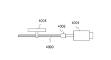
- It is a figure which shows the drive system which consists of a motor, a coupling, and a ball screw.
- FIG. 4 is a characteristic diagram showing the relationship between friction torque and angular velocity of a motor
- 1 is a configuration diagram showing a configuration of a machining center for machining turbine blades W
- FIG. FIG. 4 is a characteristic diagram for explaining an in-position check
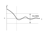
- FIG. 10 is a characteristic diagram for explaining a speed stop determination width
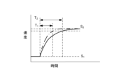
- FIG. 4 is a characteristic diagram for explaining a velocity arrival width and a waiting time until the velocity enters the arrival width
- FIG. 5 is a characteristic diagram showing an X-axis command speed, an X-axis speed output from an axis motion simulation unit, and a waiting time
- It is a flowchart which shows the machining time prediction operation
- FIG. 4 is a block diagram showing a configuration in which a Z-axis motion simulation section operates following motion of a spindle motion simulation section;
- FIG. 4 is a diagram showing a configuration example in which an X-axis motion simulation section and a Z-axis motion simulation section are connected to the same DC bus;
- FIG. 4 is a characteristic diagram showing the relationship between the maximum torque and rotation speed of the motor;
- FIG. 10 is a characteristic diagram showing a predicted waiting time and a waiting time in consideration of the NT characteristic assuming that ⁇ max of the region R1 is also applied to the region R2.
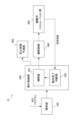
- FIG. 1 is a block diagram showing the configuration of a machining time prediction device according to the first embodiment of the present disclosure.
- the machining time prediction device 10 includes an analysis section 100 , an execution control section 200 , an axis control section 300 , an axis operation simulation section 400 and a machining time prediction section 500 .
- the execution control unit 200 has an interpolation unit 201 and an operation completion determination unit 202 .
- the machining time prediction device 10 predicts the machining time (execution time of the machining program) of a machine tool that controls at least one axis to machine a workpiece based on the machining program.
- the analysis unit 100, the interpolation unit 201, and the axis control unit 300 constitute a numerical control device (hereinafter referred to as NC device).
- the operation completion determination section 202 may be provided inside the NC device together with the interpolation section 201, or may be provided outside the NC device.
- the machining time prediction unit 500 may be provided within the NC device. Each part constituting the machining time prediction device 10 will be described below.
- the analysis unit 100 interprets an NC (Numerical Control) program, which is a machining program that defines feed axis positioning and spindle speed control operations, decomposes the NC program into codes and values, and analyzes the movement distance, movement path, and Obtain the command speed (which will be the operation command for the axis).
- NC Genetic Control
- the execution control unit 200 has an interpolation unit 201 and an operation completion determination unit 202 .
- the interpolator 201 supervises the execution of motion commands and instructs the motion of the axes based on the results of analysis of the NC program. Specifically, based on the movement distance, straight line or arc movement path, and command speed obtained by the analysis unit 100, interpolation data (axis operation instruction and ) and outputs interpolation data to the axis control unit 300 .
- the operation completion determination unit 202 determines the completion of the axis operation based on the control command output from the axis control unit 300 or the axis operation simulation unit 400 and the virtual performance output from the axis operation simulation unit 400 .
- the virtual results are, for example, the feed axis position, position deviation, speed or speed deviation, and spindle speed output from the shaft motion simulation unit 400 .
- the operation completion determination unit 202 for example, confirms operation completion for a movement command (positioning) for a feed axis and operation completion for a rotation speed change (speed change) of a main axis based on the virtual results. The details of the operation completion confirmation operation by the operation completion determination unit 202 will be described later.
- the axis control unit 300 generates a control command based on the axis operation instruction from the interpolation unit 201 and outputs it to the axis operation simulation unit 400 . Specifically, the axis control unit 300 generates an acceleration/deceleration profile based on the interpolated data, and further distributes it to each control axis, so that the servo motor serving as the feed axis electric motor and the main shaft serving as the main shaft electric motor are generated. A position command value or a speed command value for each motor control cycle is given to the shaft motion simulation unit 400 .
- the axis operation simulation unit 400 performs servo control for following the position command value or speed command value in driving the electric motor that drives the feed axis and the spindle, and simulates the operation of the machine tool, and provides the virtual results to the operation completion determination unit 202. Output. Further, the axis operation simulation unit 400 outputs control commands such as position command values and speed command values to the operation completion determination unit 202 . The details of the shaft motion simulation by the shaft motion simulation unit 400 will be described later.
- the machining time prediction unit 500 obtains the command time of the machining program using the movement distance, the movement path, the command speed, etc. obtained by the analysis unit 100, and the obtained command time and the axis control unit 300 or the operation completion determination unit 202
- the machining time (execution time of the machining program) is predicted from the control command output from and the waiting time obtained from the notification of completion confirmation from the operation completion determination unit 202 .
- the control command input to the machining time prediction unit 500 may be output from the axis control unit 300 or the axis motion simulation unit 400. The details of the machining time prediction operation by the machining time prediction unit 500 will be described later.
- the waiting time is, for example, deceleration to the position range of the designated width or the range of the stop judgment width judged to stop at speed "0" after the speed command value is set to speed "0" (stop). is the time it takes to reach Further, the waiting time is, for example, the time from when the speed command value is set to the target speed until the speed increases and the target speed reaches the target speed range.
- the machining time prediction unit 500 predicts the machining time by adding the total command time and the total waiting time when the axis acceleration and stop commands are repeated in the machining program.
- the axis motion simulation unit 400 simulates the motion of the feed axis that draws a trajectory based on the machining program and the spindle that rotates the tool or work.
- the axis motion simulation unit 400 is illustrated by the transfer function block diagram of FIG. 2, for example, when the axis is a feed axis.
- a block diagram of a configuration similar to that of FIG. 2 is described in Japanese Patent Application Laid-Open No. 3-110607.
- the transfer function of the shaft motion simulation unit 400 is configured by combining the transfer functions 401 to 407 .
- a transfer function 401 is a position loop transfer function, and Kp indicates a position gain.
- a transfer function 402 is the transfer function of the velocity loop, where k1 is the integral gain and k2 is the proportional gain.
- Transfer functions 403 and 404 are transfer functions of the motor. Kt is the torque constant, and Jm is the motor inertia (moment of inertia).
- a transfer function 405 indicates a ball screw or the like that is a coupling portion between the servomotor and the machine.
- Transfer function 406 is the transfer function of the machine, and J L represents the inertia of the machine.
- Transfer function 407 is the transfer function of the integral element that integrates the velocity of the moving parts of the machine to determine the position of the machine.
- a position loop indicated by transfer function 401 and a velocity loop indicated by transfer function 402 are servo control models, and motors, ball screws, etc. and integral elements indicated by transfer functions 403, 404, 405, 406 and 407 are plant models. .
- the angular velocity of the servomotor can be obtained by the differential equation of Equation 1 (Equation 1 below). A numerical solution using this differential equation is included in the plant model.
- Equation 1 ⁇ is angular velocity
- ⁇ is torque
- Jm motor inertia.
- a feedback signal Pf of the machine position detected by a linear scale or the like is subtracted from the position command Pc output from the axis control unit 300 to obtain a position deviation . is required.
- a feedback value Vf of the motor speed detected by a pulse coder or the like attached to the servomotor is subtracted from this speed command Vc to obtain a speed deviation, and proportional integration is performed to obtain a torque command Tc (current command).
- the servomotor is driven based on Tc, and the position and speed of the servomotor are feedback-controlled in a closed-loop manner.
- the shaft operation simulation unit 400 is configured such that the transfer function 407 integrates the angular velocity of the servomotor to obtain the angle of the servomotor, and the value obtained by converting the angle of the servomotor into the position of the machine is regarded as the position of the machine. good too.
- the shaft motion simulation unit 400 is illustrated by the block diagram of the transfer function in FIG. 3, for example, when the shaft is the main shaft.
- the block diagram shown in FIG. 3 corresponds to the block diagram shown in FIG. 2 with the transfer functions 401, 407 associated with the loop of the machine position feedback signal Pf removed.
- the transfer functions 402, 403, 404 shown in FIG. 3 are the same as the transfer functions 402, 403, 404 shown in FIG.
- the motors represented by transfer functions 403, 404 in FIG. 3 are servo motors or induction motors.
- Transfer function 406 in FIG. 3 is the transfer function of the principal axis.
- the transfer function 405 in FIG. 3 is the connection between the motor and the main shaft. Alternatively, the speed may be increased and transmitted to the main shaft.
- a transfer function 404 of the motor outputs a value Vf obtained by converting the angular velocity of the motor to the rotation speed of the main shaft, and a transfer function 402 of the speed loop performs speed control so that the output Vf of the transfer function 404 matches the main shaft rotation speed command Vc. conduct.
- FIG. 3 functions as a spindle motion simulation section even with a configuration in which the output of the transfer function 406 is Vf. Furthermore, even if transfer functions 405 and 406 are removed in FIG. 3, if Jm is the sum of the motor inertia and the main shaft inertia, it functions as a spindle motion simulation section.
- the shaft motion simulation unit 400 is shown in the block diagram of FIG. 4, for example, when the shaft is the main shaft and the motor is the induction motor.
- a block diagram of a configuration similar to that of FIG. 4 is described in JP-A-2020-5406.
- the block diagram shown in FIG. 4 shows the proximity switch, the rotation speed calculation unit using the number of pulses detected by the proximity switch, and the speed command correction unit shown in the block diagram described in Japanese Patent Application Laid-Open No. 2020-5406. is removed.
- the configuration and operation of the shaft operation simulation unit 400, excluding the proximity switch, the rotation speed calculation unit that uses the number of pulses detected by the proximity switch, and the speed command correction unit, are described in Japanese Patent Application Laid-Open No. 2020-5406. Since the configuration and operation are the same, detailed description is omitted.
- the shaft motion simulation section 400 includes a subtractor 411, a speed control section 412, a current control section 413, a primary frequency control section 414, a slip frequency calculation section 415, a subtractor 416, two-phase and three-phase A conversion unit 417 and an induction motor 418 are provided.
- a subtractor 411 obtains a difference between a speed command value output from the shaft control unit 300 and a rotation speed estimated value output from a subtractor 416, which will be described later, and outputs a speed deviation.
- a speed control unit 412 generates a current command value (torque command value) by performing, for example, PI (proportional, integral) control on the speed deviation obtained by the subtractor 411 .
- a current control unit 413 determines a voltage command value (a d-phase voltage command value and a q-phase voltage command value).
- a primary frequency control unit 414 generates a primary frequency command value based on the current command value (torque command value) generated by the speed control unit 412 .
- the slip frequency calculation unit 415 calculates an estimated slip frequency value based on the current command value (torque command value) generated by the speed control unit 412 .
- a subtractor 416 obtains the difference between the primary frequency command value from the primary frequency control unit 414 and the estimated slip frequency value obtained by the slip frequency calculation unit 415, and outputs it as a rotational speed calculation value of the induction motor 418. do.
- the two-phase-to-three phase conversion unit 417 Based on the primary frequency command value from the primary frequency control unit 414, the two-phase-to-three phase conversion unit 417 converts the d-phase voltage command value and the q-phase voltage command value generated by the current control unit 413 into UVW components.
- a voltage command value for driving the induction motor 418 is generated by converting to a phase voltage command value.
- the drive current value of the induction motor 418 can be calculated, for example, by giving the previously generated voltage command value to the state equation of the induction motor 418 as a voltage.
- the equation of state of the induction motor and the method of calculating the current are described, for example, in the non-patent document Murata, Tsuchiya, and Takeda, ⁇ Primary magnetic flux linkage vector control of induction motors'', Transactions of the Society of Instrument and Control Engineers, Vol.25, No.11 P1194- 1201 (1989).
- Equation 2 the friction torque fm acting on the motor 4001 is expressed by Equation 2 (equation 2 below).
- Equation 2 The relationship between the friction torque fm and the angular velocity ⁇ m of the motor is shown in the characteristic diagram of FIG.
- J m represents the sum of the inertia moments of the rotor, coupling, and ball screw of the motor
- ⁇ m represents the angular velocity of the motor.
- a simulation is performed to update the angular velocity ⁇ m every time ⁇ t.
- Frictional torque f L [k] acting on the table can be obtained by changing the subscript of Equation 2 and FIG. 6 from “m" to "L".
- JL is a value obtained by converting the mass of the table into a moment of inertia
- ⁇ L is a value obtained by converting the velocity of the table into an angular velocity.
- Equation (3) The torque ⁇ m[k] applied to the motor and the torque ⁇ L[k] applied to the table are obtained using Equation (3).
- Equation 3 ⁇ in is the input torque supplied to the motor, and Ks is the torsional stiffness between the motor and the table.
- Equation 4 the relational expression of Equation 4 (Equation 4 below) is obtained.
- ⁇ m is the angular velocity of the motor
- ⁇ L is the torque applied to the motor, which is the angular velocity obtained by converting the velocity of the table into angular velocity. Since the static friction F is a factor that deteriorates the servo controllability at low speeds, by considering the static friction in the calculation of the angular velocity, it is possible to improve the prediction accuracy of the operation completion waiting time, which will be described later.
- the axis motion simulation section can change whether the axis motion simulation is for a feed axis or a main axis by a command from the machining program.
- contour control rotation axis for example, see https://www.jmtba.or.jp/exportcontrol "9.
- Concept of contour control rotation axis and indexing axis (2018.7.24)" "Axes that have an axis name, are controlled by a numerical controller (NC) on the main body of the machine tool, are intended for turning, milling, and grinding (hereinafter referred to as "cutting") and satisfy all of the following: is the axis of rotation that can be contoured.
- NC numerical controller
- Axes that can use rotary motion as cutting feed (2) Axes that can command cutting feed simultaneously with other linear axes and rotary axes (3) When commanded simultaneously with other linear axes and rotary axes, Axis that interpolates along the specified path".
- FIG. 7 is a configuration diagram showing the configuration of a machining center for machining turbine blades W.
- the machining center shown in FIG. 7 has a pair of pedestals 421a and 421b having clamping mechanisms 424a and 424b capable of holding turbine blades W, and a pedestal 423 on which a tool T can be mounted.
- Servomotors 422a, 422b for rotating are incorporated.
- the table 421a is installed in such a posture that the axis can rotate around the A1 axis parallel to the horizontal axis.
- the table 421b is installed in such a posture that the clamp mechanisms 424a and 424b are opposed to each other and the main shaft is rotatable around the A2 axis coaxial with the A1 axis.
- the platform 421b is slidable in the U-axis direction parallel to the A1-axis and A2-axis (also the X-axis in FIG. 1). Further, the table 423 is rotatable around a B-axis parallel to the front-rear direction (Y-axis direction) in FIG. Further, the tool T is mounted on a spindle (not shown) inside the table 423 and is rotatable together with the spindle by a servomotor (not shown).
- a machining program for machining a workpiece W into a turbine blade is being executed in the machining center of FIG.
- the A1 and A2 axes act as feed axes.
- a rotary tool T such as an end mill is used to machine the blade shape at the center of the work.
- the A1 and A2 axes operate as main axes. Turning is performed on a rotating work W using a tool T such as a cutting tool.
- the A1 and A2 axes are rotary axes driven by the servo motors 422a and 422b, and become feed axes or main axes in the course of the machining program according to instructions from the machining program.
- the motion completion determination unit 202 determines the completion of motion based on the control command output from the axis control unit 300 or the shaft motion simulation unit 400 and the virtual performance output from the shaft motion simulation unit 400. to judge.
- (1) Judgment Operation of Operation Completion at Stop Operation completion judgment unit 202 determines that when the speed command value is set to speed “0” (stop), the feed axis or main axis is decelerated and the specified width is reached. Completion of the operation is judged based on whether it has entered the position range or the range of the stop judgment width for judging the stop of the speed "0". Whether or not the feed axis or main shaft has been decelerated and has entered the position range of the specified width is determined by the operation completion determination unit 202 determining the positioning of the feed shaft or main shaft by an in-position check.
- the operation completion determination unit 202 performs an in-position check when the speed command value is set to speed "0" (stop), and determines that the operation is completed if the in-position is reached. In-position means that the motor has arrived within the width of the commanded position.
- FIG. 8 is a characteristic diagram for explaining the in-position check.
- the characteristic diagram shown in FIG. 8 shows the relationship between the time T and the X-axis speed command and the positional deviation amount at the time T. As shown in FIG. The positional deviation amount is a virtual actual result.
- the operation completion determination unit 202 sequentially acquires the X-axis speed command value at time T from the axis control unit 300 or the axis operation simulation unit 400 , and also acquires the position deviation amount at time T from the axis operation simulation unit 400 . Then, the operation completion determination unit 202 performs an in-position check when the X-axis speed command value becomes speed "0" (stop) in block Nxx of the machining program, and the position deviation amount is set in advance.
- the interpolation unit 201 When it becomes equal to or less than the in-position width, it is determined that the operation is completed, and the interpolation unit 201 is notified of the operation completion confirmation.
- the interpolation unit 201 starts the operation of the next block Nyy upon receiving the operation completion confirmation notification.
- the operation completion determination unit 202 notifies the processing time prediction unit 500 of operation completion confirmation.
- the machining time prediction unit 500 recognizes the end of the block Nxx and measures the machining time.
- the operation completion determination unit 202 may determine the completion of the operation during deceleration based on whether the speed has entered the stop determination range without depending on the in-position check.
- FIG. 9 is a characteristic diagram for explaining the speed stop determination range.
- the motion completion determination unit 202 sequentially acquires the speed of the X-axis at time T from the axis motion simulation unit 400 .
- the operation completion determination unit 202 determines that the operation is completed, and performs interpolation.
- the unit 201 is notified of operation completion confirmation.
- the interpolation unit 201 When the interpolation unit 201 receives the operation completion confirmation notification, the interpolation unit 201 starts the operation of the next block. Further, the operation completion determination unit 202 notifies the processing time prediction unit 500 of operation completion confirmation. When receiving the operation completion confirmation notification, the machining time prediction unit 500 recognizes the end of the block and measures the machining time.
- FIG. 10 is a characteristic diagram for explaining the arrival width of the speed and the waiting time until the speed enters the arrival width during acceleration.
- the motion completion determination unit 202 sequentially acquires the speed of the feed shaft or the rotation speed of the main shaft at time T from the shaft motion simulation unit 400 . Then, the operation completion determination unit 202 determines that the operation is completed when the speed of the feed axis or the rotation speed of the main shaft reaches a preset range, and notifies the interpolation unit 201 of operation completion confirmation.
- the operation completion determination unit 202 notifies the processing time prediction unit 500 of operation completion confirmation.
- the machining time prediction unit 500 measures the machining time when receiving the operation completion confirmation notification. Even during deceleration, the operation completion determination unit 202 can determine that the operation is completed when the speed of the feed shaft or the rotation speed of the main shaft reaches a preset range.
- the machining time prediction unit 500 measures the time required to execute the machining program and predicts the machining time. For example, as already described, the machining time prediction unit 500 obtains the command time of the machining program using the movement distance, the movement path, the command speed, etc. obtained by the analysis unit 100, and the obtained command time and the axis control The time required for executing the machining program is measured from the control command output from the unit 300 or the operation completion determination unit 202 and the waiting time obtained from the completion confirmation notification from the operation completion determination unit 202, and the machining time is predicted. I do. Machining time can be obtained from the sum of the command time and the waiting time.
- FIG. 11 is a characteristic diagram showing the X-axis command speed, the X-axis speed output from the axis motion simulation section, and the waiting time.
- the method of obtaining the command time of the machining program using the analysis result of the analysis unit 100 is performed using a known technology, for example, the technology related to the machining time prediction device disclosed in Japanese Patent Application Laid-Open No. 2012-093975. can be done.
- Japanese Patent Application Laid-Open No. 2012-093975 discloses an NC command decoding unit that decodes NC commands, a segment data generation unit that divides a tool path into segments that are fine sections, an intermediate memory that stores segment data, and a segment tangent line.
- a speed constraint processing unit that obtains the speed in the direction
- a segment movement time calculation unit that calculates the time required for the tool to move each segment based on the speed obtained by the speed constraint processing unit, and a time required to move each segment.
- a machining time prediction device is described which is provided with a total movement time calculation unit for calculating the total tool movement time, and which calculates the time required for the tool to move along a path designated by an NC command.
- the method of obtaining the waiting time at the time of stop is based on the time t2 at which the operation is completed determined by the operation completion determining unit 202 and the speed of the X-axis command speed becomes "0" (stop). It is obtained by taking the difference from the time t1 when A method of obtaining the waiting time during acceleration can be performed in the same manner.
- the machining time prediction unit 500 adds the total command time and the total waiting time (aggregates the command time and the waiting time), Predict machining time.
- the time required to execute the machining program refers to, for example, the time from when the analysis of the machining program is started to when it is determined that the operation of the last block of the machining program has been completed.
- the machining time is determined as the sum of the command time and the waiting time
- several implementation means can be assumed as to how to set the respective timings for starting and completing the execution of the machining program. It is possible. Considering that the present invention focuses on the axis operation command time and the operation completion waiting time, it does not matter whether the start of execution is set before the start of the first axis operation command, or when the execution is started. It does not affect the gist of the invention even if the completion is set anywhere after the operation completion judgment of the last axis operation.
- FIG. 12 is a flow chart showing the operation of the machining time prediction device 10.
- the analysis unit 100 interprets the NC program and obtains the movement distance, the movement path, and the command speed.
- the interpolator 201 generates interpolated data
- the axis controller 300 generates a position command value or a speed command value based on the interpolated data.
- step S12 the axis operation simulation unit 400 performs servo control for following the position command value or the speed command value in driving the electric motor that drives the feed axis and the spindle, and simulates the operation of the machine tool, and the virtual result is the operation completion.
- Output to determination unit 202 the axis operation simulation unit 400 performs servo control for following the position command value or the speed command value in driving the electric motor that drives the feed axis and the spindle, and simulates the operation of the machine tool, and the virtual result is the operation completion.
- step S13 based on the command output from the interpolation unit 201 and the virtual performance output from the axis motion simulation unit 400, the completion of the motion is determined.
- step S14 the machining time prediction unit 500 obtains the command time of the machining program using the interpolated data obtained by the interpolation unit 201, and obtains the waiting time from the completion confirmation notification from the operation completion determination unit 202.
- step S15 the machining time prediction unit 500 adds the total command time and the total waiting time (counts the command time and waiting time) to predict the machining time.
- FIG. 13 is a block diagram showing the configuration of a machining time prediction device according to the second embodiment of the present disclosure.
- the machining time prediction device 10A shown in FIG. The axis motion simulation section 400 is divided into an X-axis motion simulation section 400A, a Z-axis motion simulation section 400B, and a spindle motion simulation section 400C, and a model setting section 600 is added.
- the interpolation section 201 is divided into a feed axis interpolation section 201A and a spindle instruction section 203, and the functions are separated.
- the model setting section 600 sets the constants of the simulation models of the X-axis motion simulation section 400A, the Z-axis motion simulation section 400B, and the spindle motion simulation section 400C. For example, when the simulation models of the X-axis motion simulation section 400A and the Z-axis motion simulation section 400B are shown in the block diagram of the transfer function in FIG . Set constants such as J m and inertia J L of the machine.
- the feed axis interpolation unit 201A and the spindle command unit 203 are capable of performing operations mutually referring to the virtual results.
- the spindle instruction unit 203 refers to the virtual result output from the Z-axis motion simulation unit 400B when performing constant peripheral speed control in lathe machining in which the rotation speed is increased as the center is approached.
- the fact that the feed axis interpolation unit 201A refers to the virtual result output from the spindle motion simulation unit 400C simultaneously interpolates the spindle and the feed axis, precisely synchronizing the rotation of the tool and the movement of its Z axis, is a rigid and rigid type. This is done in the case of tap control.
- a feed axis servo control unit is sometimes required to control the feed operation of the feed axis so as to follow the operation of the main axis.
- the feed axis controls synchronous operation (a so-called master-slave synchronous system) in which it operates to follow the rotational movement of the main shaft while taking into account the thread pitch specified by the tapping program.
- synchronous operation a so-called master-slave synchronous system
- the configuration of the shaft motion simulation when the feed motion of the feed shaft is controlled to follow the motion of the main shaft will be described with reference to FIG. 14 .
- FIG. 14 is a block diagram showing a configuration of a modification in which the Z-axis motion simulation section 400B operates following the motion of the spindle motion simulation section 400C.
- the Z-axis motion simulation section 400B has the same configuration as shown in FIG. 2, and the spindle motion simulation section 400C has the same configuration as shown in FIG.
- the rotation speed calculation unit 421 of the spindle motion simulation unit 400C outputs the rotation speed calculation value of the spindle (which becomes the virtual actual results of the other axes) to the Z-axis control unit 300B.
- the Z-axis control unit 300B calculates the amount of motion of the feed axis following the motion of the main shaft from the calculated value of the rotation speed of the main shaft, and outputs the position command P c (axis control command ) is output.
- the Z-axis control unit 300B integrates the rotation speed calculation value of the main shaft to obtain the rotation amount of the main shaft, and multiplies the rotation amount of the main shaft by the screw pitch to calculate the feed movement amount of the feed axis that follows the operation of the main shaft. can do.
- FIG. 15 is a diagram showing a configuration example in which the X-axis motion simulation section and the Z-axis motion simulation section are connected to the same DC bus. Although the X-axis motion simulation section and the Z-axis motion simulation section are connected to the same DC bus here, the X-axis motion simulation section and the Z-axis motion simulation section may be connected to the DC bus, respectively. .
- the axis motion simulation unit shown in FIG. 15 includes a plurality of machines driven by motors.
- the X-axis motion simulation section 400A includes a servo control section 441, an inverter 442, a motor 443, a coupling 444, a ball screw 445 and a table 446.
- the servo control unit 441 serves as a servo control model.
- the inverter 442, motor 443, coupling 444, ball screw 445 and table 446 are plant models.
- the Z-axis motion simulation section 400B includes a servo control section 451, an inverter 452, a motor 453, a coupling 454, a ball screw 455 and a table 456.
- the servo control unit 451 serves as a servo control model.
- the inverter 452, motor 453, coupling 454, ball screw 455 and table 456 are plant models.
- Servo control 441 and servo control 451 are represented by position loop transfer function 401 and velocity loop transfer function 402, respectively, in FIG.
- Motor 443 and motor 453 are represented by motor transfer functions 403 and 404, respectively, in FIG.
- Coupling 444 and ball screw 445 and coupling 444 and ball screw 445 are each illustrated by transfer function 405 in FIG.
- Tables 446 and 456 are each represented by transfer function 406 in FIG.
- An AC voltage supplied from an AC power supply 431 is rectified by a rectifier 432, and the rectified voltage by a smoothing capacitor 433 is smoothed.
- the regenerative resistor 434 consumes the regenerative power when excess regenerative power is generated and the DC bus voltage (bus voltage) VD reaches a specified value, and the regenerative transistor 435 consumes the regenerative power when the bus voltage reaches the specified value. In this case, the power stored in the smoothing capacitor 433 is consumed by the regenerative resistor 434 .
- the DC bus is connected to inverter 442 and inverter 452 , and DC bus voltage V D is applied to inverter 442 and inverter 452 .
- the servo control unit 441 gives a voltage command to the inverter 442 based on the position command value or speed command value output from the X-axis control unit 300A.
- the servo control unit 451 gives a voltage command to the inverter 452 based on the position command value or speed command value output from the Z-axis control unit 300B.
- the inverters 442 and 452 perform PWM (Pulse Width Modulation) calculations and the like on the DC bus voltage VD , respectively, and perform power conversion so that voltage commands are applied to the motors 443 and 453, thereby supplying current to the motors 443 and 453. supply.
- PWM Pulse Width Modulation
- the maximum torque Tor of the motor changes according to the rotation speed N, as shown in the characteristic diagram of FIG.
- the NT characteristics also change with the DC link voltage.
- region R1 shown in FIG. 16 narrows.
- the relationship between the DC link voltage VD and the region R1 is as follows.
- the R1 region is a region where Expression 5 (Equation 5 below) holds.
- Equation 5 ⁇ LIM is the motor's electrical and mechanical allowable torque
- Kt is the torque constant
- Rm is the winding resistance.
- ⁇ maX ⁇ LIM
- transition to region R2 occurs when Equation 6 (Equation 6 below) is established and depends on the DC link voltage VD .
- Equation 7 holds, and again ⁇ max depends on the DC bus voltage VD .
- Equation 8 If torsional rigidity, table inertia, and friction are ignored in Equation 4, the relational expression of angular velocity ⁇ m shown in Equation 8 is obtained.
- the relational expression of the angular velocity ⁇ m shown in Equation 8 is obtained using the differential equation shown in Equation 1.
- ⁇ in is calculated by speed servo control, but cannot exceed the maximum value ⁇ max determined by NT characteristics. Machine tool spindles are often required to accelerate and decelerate between low and high speed ranges at maximum torque.
- calculating ⁇ m by Equation 8 in consideration of NT characteristics increases the prediction accuracy of the speed arrival waiting time.
- time T1 indicates the predicted waiting time assuming that ⁇ max of region R1 is also applied to region R2, and time T2 is the waiting time in consideration of NT characteristics.
- the machining time prediction device can be realized by hardware, software, or a combination thereof.
- “implemented by software” means implemented by a computer reading and executing a program.
- the machining time prediction device is an arithmetic processing unit such as a CPU (Central Processing Unit) Prepare.
- the machining time prediction device includes an auxiliary storage device such as an HDD (Hard Disk Drive) that stores various control programs such as application software or an OS (Operating System), and a temporary It also has a main memory such as RAM (Random Access Memory) for storing the data that is actually needed.
- auxiliary storage device such as an HDD (Hard Disk Drive) that stores various control programs such as application software or an OS (Operating System)
- main memory such as RAM (Random Access Memory) for storing the data that is actually needed.
- the arithmetic processing unit reads the application software or OS from the auxiliary storage device, and while developing the read application software or OS in the main storage device, performs arithmetic processing based on the application software or OS. do Also, based on the result of this calculation, various hardware included in each device is controlled. This implements the functional blocks of the present embodiment.
- Each component included in the machining time prediction device can be realized by hardware including electronic circuits.
- some or all of the functions of each component included in the machining time prediction device for example, ASIC (Application Specific Integrated Circuit), gate array, FPGA (Field Programmable Gate Array ), CPLD (Complex Programmable Logic Device), or other integrated circuit (IC).
- ASIC Application Specific Integrated Circuit
- FPGA Field Programmable Gate Array
- CPLD Complex Programmable Logic Device
- IC integrated circuit
- Non-transitory computer readable media include various types of tangible storage media.
- Examples of non-transitory computer-readable media include magnetic recording media (e.g., hard disk drives), magneto-optical recording media (e.g., magneto-optical discs), CD-ROMs (Read Only Memory), CD-Rs, CD-R/ W, including semiconductor memory (eg, mask ROM, PROM (programmable ROM), EPROM (erasable PROM), flash ROM, RAM (random access memory));
- the program may also be delivered to the computer on various types of transitory computer readable medium.
- the machining time prediction device and the machining time prediction method according to the present disclosure can take various embodiments having the following configurations, including the embodiments described above.
- a machining time prediction device for example, machining time prediction devices 10 and 10A that predicts the machining time of a machine tool that controls at least one axis to machine a workpiece based on a machining program, an analysis unit (e.g., analysis unit 100) that analyzes the machining program and generates an operation command for the axis;
- An interpolating unit for example, an interpolating unit 201 that supervises the execution of the operation command and instructs the operation of the axis from the result of analyzing the machining program, and an operation completion determination unit that determines that the operation of the axis is completed.
- an execution control unit e.g., execution control unit 200
- execution control unit 200 including (e.g., operation completion determination unit 202); an axis control unit (for example, an axis control unit 300) that generates a control command based on the operation instruction of the axis from the interpolation unit;
- a machining time prediction unit for example, a machining time prediction unit 500
- shaft motion simulation unit for example, a shaft motion simulation unit 400
- the motion completion determination unit determines completion of the motion of the axis based on the virtual performance.
- Machining time prediction device According to this machining time prediction device, without using actual machining data, even if the machining program frequently issues an axis stop command or if the machine tool is equipped with a large inertia axis, an accurate Machining time can be predicted.
- axis motion simulation by the axis motion simulation unit is performed for the feed axis or the spindle can be changed by a command from the machining program. Machining time prediction device as described.
- a model setting unit capable of changing characteristics of the shaft operation simulation unit;
- the axis motion simulation unit a servo control model that causes the virtual performance to follow the control command;
- a plant model that includes a numerical solution method for one or more differential equations and calculates the virtual performance when a manipulated variable that is an output of the servo control model is input;
- the machining time prediction device according to any one of (1) to (4) above, comprising:
- the plant model includes an electric motor driven by an inverter as a power source for the shaft;
- the machining time prediction device according to (5) above, wherein the DC bus voltage to which the inverter is connected can be calculated.
- a computer as a machining time prediction device that predicts the machining time of a machine tool that controls at least one axis to machine a workpiece based on a machining program, a process of analyzing the machining program and generating an operation command for the axis; supervising the execution of the motion commands, instructing the motion of the axes based on the result of analyzing the machining program; a process of determining that the movement of the axis is complete; a process of generating a control command based on the operation instruction of the axis; a process of measuring the time required to execute the machining program and estimating the machining time; Axis operation simulation processing for simulating the operation of the axis and outputting a virtual result based on the control command; and run determining completion of the axis operation based on the virtual performance in the process of determining the completion of the axis operation; Machining time prediction method. According to this machining time prediction method, without using actual machining data, even if the machining program and
Abstract
The present invention enables accurate prediction of machining time without using actual machining data. A machining time prediction device for a machine tool that controls at least one axis to machine a workpiece on the basis of a machining program, the machining time prediction device comprising: an analysis unit that analyzes the machining program and generates operation instructions for the axis; an execution control unit equipped with an interpolation unit that supervises the execution of operation instructions, and instructs the operation of the axis on the basis of the result of analyzing the machining program and an operation completion determination unit that determines that the operation of the axis is complete; an axis control unit that generates control commands on the basis of the axis operation instructions; a machining time prediction unit that measures the time required to execute the machining program and predicts the machining time; and an axis operation simulation unit that simulates the operation of the axis on the basis of the control commands and outputs virtual performance. The operation completion determination unit determines the completion of the operation of the axis on the basis of the virtual performance.
Description
本発明は、工作機械の加工時間予測装置及び加工時間予測方法に関し、特に、加工プログラムに基づき、少なくとも1つの軸を制御してワークを加工する工作機械の加工時間を予測する加工時間予測装置及び加工時間予測方法に関する。
The present invention relates to a machining time prediction device and a machining time prediction method for a machine tool, and more particularly to a machining time prediction device and a machining time prediction method for predicting the machining time of a machine tool that controls at least one axis to machine a workpiece based on a machining program. The present invention relates to a machining time prediction method.
機械加工を効率よく行うためには、加工前に各工程の所要時間を把握しておく必要がある。特に、CNC工作機械の加工プログラムを実行するための所要時間を把握することは重要である。
In order to perform machining efficiently, it is necessary to know the time required for each process before machining. In particular, it is important to know the time required to execute the machining program of the CNC machine tool.
特許文献1には、許容加工誤差内で最も短い予測加工時間を求める数値制御装置が記載されている。
具体的には、特許文献1には、ワークの加工を行う際の加工速度を与える速度データと加工精度を与える精度データを指定し、加工プログラムに対しプログラム解析部が補間用データを作成し、補間部が補間前加減速部によって作成された速度に基づいて補間用データにしたがって補間を行って補間データ(ΔPn)を作成し、補間後加減速部が補間データ(ΔPn)に対して補間後加減速を行いサーボ位置指令データ(VCn)を作成することが記載されている。そして、特許文献1には、サーボシミュレーション部がサーボ位置指令データ(VCn)を受け取り、実際のサーボ動作をシミュレーションしたサーボ位置データ(Qn)を作成し、加工時間予測部が補間データによりまたは補間回数をカウントすることにより加工時間を測定でき、加工誤差予測部が補間データ(ΔPn)とサーボ位置データ(Qn)を用い予測加工誤差を求めることが記載されている。Patent Literature 1 describes a numerical control device that obtains the shortest predicted machining time within an allowable machining error.
Specifically, inPatent Document 1, speed data that gives a machining speed and accuracy data that gives a machining accuracy when machining a workpiece are specified, and a program analysis unit creates interpolation data for a machining program, The interpolating section performs interpolation according to the interpolation data based on the velocity created by the pre-interpolation acceleration/deceleration section to create interpolation data (ΔPn), and the post-interpolation acceleration/deceleration section performs interpolation on the interpolation data (ΔPn) after interpolation. It describes that acceleration/deceleration is performed to create servo position command data (VCn). In Patent Document 1, a servo simulation unit receives servo position command data (VCn), creates servo position data (Qn) by simulating an actual servo operation, and a machining time prediction unit predicts the number of times of interpolation based on the interpolation data. It is described that the machining time can be measured by counting , and that the machining error prediction unit obtains the predicted machining error using interpolation data (ΔPn) and servo position data (Qn).
具体的には、特許文献1には、ワークの加工を行う際の加工速度を与える速度データと加工精度を与える精度データを指定し、加工プログラムに対しプログラム解析部が補間用データを作成し、補間部が補間前加減速部によって作成された速度に基づいて補間用データにしたがって補間を行って補間データ(ΔPn)を作成し、補間後加減速部が補間データ(ΔPn)に対して補間後加減速を行いサーボ位置指令データ(VCn)を作成することが記載されている。そして、特許文献1には、サーボシミュレーション部がサーボ位置指令データ(VCn)を受け取り、実際のサーボ動作をシミュレーションしたサーボ位置データ(Qn)を作成し、加工時間予測部が補間データによりまたは補間回数をカウントすることにより加工時間を測定でき、加工誤差予測部が補間データ(ΔPn)とサーボ位置データ(Qn)を用い予測加工誤差を求めることが記載されている。
Specifically, in
特許文献2には、機械で発生する機械遅れを考慮した精度の高い加工時間の予測を可能とする数値制御装置が記載されている。
具体的には、特許文献2には、数値制御装置が、加工プログラムに基づいて軸の加減速を考慮しない加工時間である基準加工時間を予測する基準加工時間予測部と、加工プログラムに基づいて加工おける軸の加減速回数を予測する加減速回数予測部と、機械による実際の加工に掛かる加工時間である実加工時間と、当該加工において予測された基準加工時間との差である乖離時間に係る情報を記憶するデータ記憶部と、加減速回数予測部が予測した加減速回数と、データ記憶部に記憶された乖離時間に係る情報とに基づいて、基準加工時間を補正するための補正時間を算出する補正時間算出部と、基準加工時間を補正時間で補正した予測加工時間を算出する加工時間予測部と、を備えることが記載されている。 Patent Literature 2 describes a numerical control device capable of highly accurate prediction of machining time in consideration of machine delays that occur in machines.
Specifically, in Patent Document 2, a numerical controller includes a reference machining time prediction unit that predicts a reference machining time, which is a machining time that does not consider acceleration/deceleration of an axis, based on a machining program, and Acceleration/deceleration number prediction unit that predicts the number of acceleration/deceleration times of the axis during machining, and deviation time that is the difference between the actual machining time that is the actual machining time required for actual machining by the machine and the reference machining time that is predicted for the machining. A correction time for correcting the reference machining time based on a data storage unit that stores such information, the number of acceleration/deceleration times predicted by the acceleration/deceleration number prediction unit, and information related to the divergence time stored in the data storage unit. and a machining time prediction unit for calculating a predicted machining time obtained by correcting the reference machining time with the correction time.
特許文献3には、加工前に正確に加工所要時間を算出することができる加工時間算出装置が記載されている。
具体的には、特許文献3には、分割軌跡算出手段が、指定工具軌跡を曲率が小さい部分は大きい間隔で分割し、指定工具軌跡の曲率が大きくなるに従って小さい間隔で分割した分割軌跡を求め、軸制御データ算出手段が、工具を指定工具移動速度に従った速度で各分割軌跡上を移動させてワークを加工するときの該分割軌跡上の任意の位置と所定の時間間隔で求めた各軸方向の工具移動速度の時間変化とを軸制御データAとして求めることが記載されている。そして、特許文献3には、加工所要時間算出手段が、指定された範囲を加工するための加工時間を算出することが記載されている。 Patent Literature 3 describes a machining time calculation device that can accurately calculate the required machining time before machining.
Specifically, in Patent Document 3, a divided trajectory calculation means divides a designated tool trajectory at large intervals in a portion where the curvature is small, and divides the designated tool trajectory at smaller intervals as the curvature increases to obtain divided trajectories. , when the axis control data calculating means moves the tool on each divided locus at a speed according to the specified tool moving speed to machine the workpiece, each position obtained at an arbitrary position on the divided locus and at a predetermined time interval It is described that the axial control data A is obtained from the time change of the tool moving speed in the axial direction. Patent Literature 3 describes that the required machining time calculation means calculates the machining time for machining the specified range.
CNC工作機械の加工プログラムに軸の停止命令が頻出する場合、及び工作機械に大慣性(応答時定数大)の軸が搭載される場合には、正確な加工時間の予測が難しい。
また、加工時間の予測に実加工のデータを用いると、データの収集に時間及び労力が必要となる。
よって、実加工のデータを用いることなく、加工プログラムで軸の停止命令が頻出する場合、及び工作機械に大慣性の軸が搭載される場合であっても、正確な加工時間の予測が可能な、工作機械の加工時間予測装置が望まれている。 Accurate prediction of the machining time is difficult when axis stop commands are frequently issued in the machining program of the CNC machine tool, and when the machine tool is equipped with an axis with a large inertia (large response time constant).
Moreover, if actual machining data is used to predict the machining time, time and labor are required to collect the data.
Therefore, it is possible to accurately predict the machining time without using actual machining data, even if there are frequent axis stop commands in the machining program, or even if the machine tool is equipped with a large inertia axis. , a machining time prediction device for a machine tool is desired.
本開示の代表的な第1の態様は、加工プログラムに基づき、少なくとも1つの軸を制御してワークを加工する工作機械の加工時間を予測する加工時間予測装置であって、
前記加工プログラムを解析して前記軸の動作命令を生成する解析部と、
前記動作命令の実行を統括し、前記加工プログラムを解析した結果から前記軸の動作を指示する補間部、及び前記軸の動作が完了したことを判断する動作完了判断部を備えた実行制御部と、
前記補間部からの前記軸の動作指示に基づいて制御指令を生成する軸制御部と、
前記加工プログラムの実行に要した時間を測定して、前記加工時間を予測する加工時間予測部と、
前記制御指令に基づき、前記軸の動作を模擬して仮想実績を出力する軸動作シミュレーション部と、
を備え、
前記動作完了判断部は、前記仮想実績に基づいて前記軸の動作の完了を判断する、
加工時間予測装置である。 A representative first aspect of the present disclosure is a machining time prediction device that predicts the machining time of a machine tool that controls at least one axis to machine a workpiece based on a machining program,
an analysis unit that analyzes the machining program and generates an operation command for the axis;
an execution control unit comprising an interpolation unit that supervises the execution of the operation command and instructs the operation of the axis from the result of analyzing the machining program, and an operation completion determination unit that determines that the operation of the axis is completed; ,
an axis control unit that generates a control command based on the operation instruction of the axis from the interpolation unit;
a machining time prediction unit that measures the time required to execute the machining program and predicts the machining time;
an axis operation simulation unit that simulates the operation of the axis based on the control command and outputs a virtual result;
with
The motion completion determination unit determines completion of the motion of the axis based on the virtual performance.
It is a machining time prediction device.
本開示の代表的な第2の態様は、加工プログラムに基づき、少なくとも1つの軸を制御してワークを加工する工作機械の加工時間を予測する加工時間予測装置としてのコンピュータが、
前記加工プログラムを解析して前記軸の動作命令を生成する処理と、
前記動作命令の実行を統括し、前記加工プログラムを解析した結果から前記軸の動作を指示し、
前記軸の動作が完了したことを判断する処理と、
前記軸の動作指示に基づいて制御指令を生成する処理と、
前記加工プログラムの実行に要した時間を測定して、前記加工時間を予測する処理と、
前記制御指令に基づき、前記軸の動作を模擬して仮想実績を出力する軸動作シミュレーション処理、
を実行し、
前記軸の動作が完了したことを判断する処理において、前記仮想実績に基づいて前記軸の動作の完了を判断する、
加工時間予測方法である。 A representative second aspect of the present disclosure is a computer as a machining time prediction device that predicts the machining time of a machine tool that controls at least one axis to machine a workpiece based on a machining program,
a process of analyzing the machining program and generating an operation command for the axis;
supervising the execution of the motion commands, instructing the motion of the axes based on the result of analyzing the machining program;
a process of determining that the movement of the axis is complete;
a process of generating a control command based on the operation instruction of the axis;
a process of measuring the time required to execute the machining program and estimating the machining time;
Axis operation simulation processing for simulating the operation of the axis and outputting a virtual result based on the control command;
and run
determining completion of the axis operation based on the virtual performance in the process of determining the completion of the axis operation;
This is a machining time prediction method.
本開示の各態様によれば、実加工のデータを用いることなく、加工プログラムで軸の停止命令が頻出する場合、及び工作機械に大慣性の軸が搭載される場合であっても、正確な加工時間の予測が可能となる。
According to each aspect of the present disclosure, even if a machining program frequently issues an axis stop command and a machine tool is equipped with a large-inertia axis, accurate Machining time can be predicted.
以下、本開示の実施形態について図面を用いて詳細に説明する。
Hereinafter, embodiments of the present disclosure will be described in detail with reference to the drawings.
(第1実施形態)
図1は本開示の第1実施形態の、加工時間予測装置の構成を示すブロック図である。
加工時間予測装置10は、解析部100、実行制御部200、軸制御部300、軸動作シミュレーション部400、及び加工時間予測部500を備えている。実行制御部200は、補間部201及び動作完了判断部202を備えている。加工時間予測装置10は、加工プログラムに基づき、少なくとも1つの軸を制御してワークを加工する工作機械の加工時間(加工プログラムの実行時間)を予測する。
解析部100、補間部201及び軸制御部300は、数値制御装置(以下、NC装置と記す)を構成する。動作完了判断部202は、補間部201とともにNC装置内に設けられても、NC装置外に設けられてもよい。加工時間予測部500は、NC装置内に設けられてもよい。
以下、加工時間予測装置10を構成する各部について説明する。 (First embodiment)
FIG. 1 is a block diagram showing the configuration of a machining time prediction device according to the first embodiment of the present disclosure.
The machiningtime prediction device 10 includes an analysis section 100 , an execution control section 200 , an axis control section 300 , an axis operation simulation section 400 and a machining time prediction section 500 . The execution control unit 200 has an interpolation unit 201 and an operation completion determination unit 202 . The machining time prediction device 10 predicts the machining time (execution time of the machining program) of a machine tool that controls at least one axis to machine a workpiece based on the machining program.
Theanalysis unit 100, the interpolation unit 201, and the axis control unit 300 constitute a numerical control device (hereinafter referred to as NC device). The operation completion determination section 202 may be provided inside the NC device together with the interpolation section 201, or may be provided outside the NC device. The machining time prediction unit 500 may be provided within the NC device.
Each part constituting the machiningtime prediction device 10 will be described below.
図1は本開示の第1実施形態の、加工時間予測装置の構成を示すブロック図である。
加工時間予測装置10は、解析部100、実行制御部200、軸制御部300、軸動作シミュレーション部400、及び加工時間予測部500を備えている。実行制御部200は、補間部201及び動作完了判断部202を備えている。加工時間予測装置10は、加工プログラムに基づき、少なくとも1つの軸を制御してワークを加工する工作機械の加工時間(加工プログラムの実行時間)を予測する。
解析部100、補間部201及び軸制御部300は、数値制御装置(以下、NC装置と記す)を構成する。動作完了判断部202は、補間部201とともにNC装置内に設けられても、NC装置外に設けられてもよい。加工時間予測部500は、NC装置内に設けられてもよい。
以下、加工時間予測装置10を構成する各部について説明する。 (First embodiment)
FIG. 1 is a block diagram showing the configuration of a machining time prediction device according to the first embodiment of the present disclosure.
The machining
The
Each part constituting the machining
解析部100は、送り軸の位置決め及び主軸の速度制御の動作を規定する加工プログラムとなるNC(Numerical Control)プログラムを解釈し、NCプログラムを各コードと値に分解し、移動距離、移動経路及び指令速度(軸の動作命令となる)を求める。
The analysis unit 100 interprets an NC (Numerical Control) program, which is a machining program that defines feed axis positioning and spindle speed control operations, decomposes the NC program into codes and values, and analyzes the movement distance, movement path, and Obtain the command speed (which will be the operation command for the axis).
実行制御部200は、補間部201及び動作完了判断部202を備えている。
補間部201は、動作命令の実行を統括し、NCプログラムを解析した結果から軸の動作を指示する。具体的には、解析部100により得られた移動距離、直線又は円弧などの移動経路、指令速度をもとに、移動経路上の点を補間周期で補間計算した補間データ(軸の動作指示となる)を生成し、軸制御部300へ補間データを出力する。 Theexecution control unit 200 has an interpolation unit 201 and an operation completion determination unit 202 .
The interpolator 201 supervises the execution of motion commands and instructs the motion of the axes based on the results of analysis of the NC program. Specifically, based on the movement distance, straight line or arc movement path, and command speed obtained by theanalysis unit 100, interpolation data (axis operation instruction and ) and outputs interpolation data to the axis control unit 300 .
補間部201は、動作命令の実行を統括し、NCプログラムを解析した結果から軸の動作を指示する。具体的には、解析部100により得られた移動距離、直線又は円弧などの移動経路、指令速度をもとに、移動経路上の点を補間周期で補間計算した補間データ(軸の動作指示となる)を生成し、軸制御部300へ補間データを出力する。 The
The interpolator 201 supervises the execution of motion commands and instructs the motion of the axes based on the results of analysis of the NC program. Specifically, based on the movement distance, straight line or arc movement path, and command speed obtained by the
動作完了判断部202は、軸制御部300又は軸動作シミュレーション部400から出力される制御指令と、軸動作シミュレーション部400から出力される仮想実績とに基づいて、軸の動作の完了を判断する。仮想実績は、例えば、軸動作シミュレーション部400から出力される、送り軸の位置、位置偏差、速度若しくは速度偏差、及び主軸回転数である。動作完了判断部202は、仮想実績に基づいて、例えば、送り軸に対する移動命令(位置決め)に対する動作完了確認、主軸の回転数変更(速度変更)に対する動作完了確認を行う。動作完了判断部202による動作完了確認の動作の詳細は後述する。
The operation completion determination unit 202 determines the completion of the axis operation based on the control command output from the axis control unit 300 or the axis operation simulation unit 400 and the virtual performance output from the axis operation simulation unit 400 . The virtual results are, for example, the feed axis position, position deviation, speed or speed deviation, and spindle speed output from the shaft motion simulation unit 400 . The operation completion determination unit 202, for example, confirms operation completion for a movement command (positioning) for a feed axis and operation completion for a rotation speed change (speed change) of a main axis based on the virtual results. The details of the operation completion confirmation operation by the operation completion determination unit 202 will be described later.
軸制御部300は、補間部201からの軸の動作指示に基づいて制御指令を生成して軸動作シミュレーション部400へ出力する。具体的には、軸制御部300は、補間データに基づいて加減速プロファイルを生成し、さらに各制御軸への分配を行うことで、送り軸の電動機となるサーボモータ及び主軸の電動機となる主軸モータの制御周期ごとの位置指令値又は速度指令値を軸動作シミュレーション部400に与える。
The axis control unit 300 generates a control command based on the axis operation instruction from the interpolation unit 201 and outputs it to the axis operation simulation unit 400 . Specifically, the axis control unit 300 generates an acceleration/deceleration profile based on the interpolated data, and further distributes it to each control axis, so that the servo motor serving as the feed axis electric motor and the main shaft serving as the main shaft electric motor are generated. A position command value or a speed command value for each motor control cycle is given to the shaft motion simulation unit 400 .
軸動作シミュレーション部400は、位置指令値又は速度指令値に、送り軸及び主軸を駆動する電動機の駆動を追従させるサーボ制御及び工作機械の動作のシミュレーションを行い、仮想実績を動作完了判断部202に出力する。また、軸動作シミュレーション部400は、位置指令値、速度指令値等の制御指令を動作完了判断部202に出力する。軸動作シミュレーション部400による軸動作シミュレーションの詳細は後述する。
The axis operation simulation unit 400 performs servo control for following the position command value or speed command value in driving the electric motor that drives the feed axis and the spindle, and simulates the operation of the machine tool, and provides the virtual results to the operation completion determination unit 202. Output. Further, the axis operation simulation unit 400 outputs control commands such as position command values and speed command values to the operation completion determination unit 202 . The details of the shaft motion simulation by the shaft motion simulation unit 400 will be described later.
加工時間予測部500は、解析部100で求めた移動距離、移動経路及び指令速度等を用いて、加工プログラムの指令時間を求め、求めた指令時間と、軸制御部300又は動作完了判断部202から出力される制御指令及び動作完了判断部202からの完了確認の通知から求められる待ち時間とから、加工時間(加工プログラムの実行時間)の予測を行う。なお、加工時間予測部500に入力される制御指令は、軸制御部300又は軸動作シミュレーション部400から出力されてもよい。加工時間予測部500による加工時間の予測動作の詳細は後述する。
待ち時間とは、例えば、速度指令値が速度“0”(停止)に設定されてから、指定された幅の位置範囲若しくは速度”0”の停止と判断される停止判断幅の範囲まで減速して到達するまでの時間をいう。また、待ち時間とは、例えば、速度指令値が目標とする速度に設定されてから、速度が増加して、目標とする速度の到達幅の範囲まで到達するまでの時間をいう。
加工時間予測部500は、加工プログラムで軸の加速と停止の命令が繰り返される場合、指令時間の合計と、待ち時間の合計とを加算して加工時間の予測を行う。 The machiningtime prediction unit 500 obtains the command time of the machining program using the movement distance, the movement path, the command speed, etc. obtained by the analysis unit 100, and the obtained command time and the axis control unit 300 or the operation completion determination unit 202 The machining time (execution time of the machining program) is predicted from the control command output from and the waiting time obtained from the notification of completion confirmation from the operation completion determination unit 202 . The control command input to the machining time prediction unit 500 may be output from the axis control unit 300 or the axis motion simulation unit 400. The details of the machining time prediction operation by the machining time prediction unit 500 will be described later.
The waiting time is, for example, deceleration to the position range of the designated width or the range of the stop judgment width judged to stop at speed "0" after the speed command value is set to speed "0" (stop). is the time it takes to reach Further, the waiting time is, for example, the time from when the speed command value is set to the target speed until the speed increases and the target speed reaches the target speed range.
The machiningtime prediction unit 500 predicts the machining time by adding the total command time and the total waiting time when the axis acceleration and stop commands are repeated in the machining program.
待ち時間とは、例えば、速度指令値が速度“0”(停止)に設定されてから、指定された幅の位置範囲若しくは速度”0”の停止と判断される停止判断幅の範囲まで減速して到達するまでの時間をいう。また、待ち時間とは、例えば、速度指令値が目標とする速度に設定されてから、速度が増加して、目標とする速度の到達幅の範囲まで到達するまでの時間をいう。
加工時間予測部500は、加工プログラムで軸の加速と停止の命令が繰り返される場合、指令時間の合計と、待ち時間の合計とを加算して加工時間の予測を行う。 The machining
The waiting time is, for example, deceleration to the position range of the designated width or the range of the stop judgment width judged to stop at speed "0" after the speed command value is set to speed "0" (stop). is the time it takes to reach Further, the waiting time is, for example, the time from when the speed command value is set to the target speed until the speed increases and the target speed reaches the target speed range.
The machining
次に、軸動作シミュレーション部400、動作完了判断部202、及び加工時間予測部500について更に説明する。
(軸動作シミュレーション部400)
軸動作シミュレーション部400は、加工プログラムに基づく軌跡を描く送り軸と、工具又はワークを回転させる主軸との動作のシミュレーションを行う。
軸動作シミュレーション部400は、例えば、軸が送り軸である場合、図2の伝達関数のブロック線図で示される。図2のブロック線図と同様な構成のブロック線図は、特開平3-110607号公報に記載されている。
軸動作シミュレーション部400の伝達関数は、伝達関数401から伝達関数407の結合により構成される。 Next, the shaftoperation simulation unit 400, operation completion determination unit 202, and machining time prediction unit 500 will be further described.
(Axis motion simulation unit 400)
The axismotion simulation unit 400 simulates the motion of the feed axis that draws a trajectory based on the machining program and the spindle that rotates the tool or work.
The axismotion simulation unit 400 is illustrated by the transfer function block diagram of FIG. 2, for example, when the axis is a feed axis. A block diagram of a configuration similar to that of FIG. 2 is described in Japanese Patent Application Laid-Open No. 3-110607.
The transfer function of the shaftmotion simulation unit 400 is configured by combining the transfer functions 401 to 407 .
(軸動作シミュレーション部400)
軸動作シミュレーション部400は、加工プログラムに基づく軌跡を描く送り軸と、工具又はワークを回転させる主軸との動作のシミュレーションを行う。
軸動作シミュレーション部400は、例えば、軸が送り軸である場合、図2の伝達関数のブロック線図で示される。図2のブロック線図と同様な構成のブロック線図は、特開平3-110607号公報に記載されている。
軸動作シミュレーション部400の伝達関数は、伝達関数401から伝達関数407の結合により構成される。 Next, the shaft
(Axis motion simulation unit 400)
The axis
The axis
The transfer function of the shaft
図2において、伝達関数401は、位置ループの伝達関数で、Kpはポジションゲインを示す。伝達関数402は、速度ループの伝達関数で、k1は積分ゲイン、k2は比例ゲインを示す。伝達関数403、404はモータの伝達関数である。Ktはトルク定数、Jmはモータイナーシャ(慣性モーメント)を示す。伝達関数405はサーボモータと機械の結合部であるボールネジ等を示す。伝達関数406は機械の伝達関数で、JLは機械のイナーシャを示す。伝達関数407は機械の可動部の速度を積分して機械の位置を求める積分要素の伝達関数である。
In FIG. 2, a transfer function 401 is a position loop transfer function, and Kp indicates a position gain. A transfer function 402 is the transfer function of the velocity loop, where k1 is the integral gain and k2 is the proportional gain. Transfer functions 403 and 404 are transfer functions of the motor. Kt is the torque constant, and Jm is the motor inertia (moment of inertia). A transfer function 405 indicates a ball screw or the like that is a coupling portion between the servomotor and the machine. Transfer function 406 is the transfer function of the machine, and J L represents the inertia of the machine. Transfer function 407 is the transfer function of the integral element that integrates the velocity of the moving parts of the machine to determine the position of the machine.
伝達関数401で示される位置ループ、伝達関数402で示される速度ループはサーボ制御モデルとなり、伝達関数403、404、405、406及び407で示される、モータ、ボールネジ等及び積分要素はプラントモデルである。
サーボモータの角速度は、数式1(以下の数1)の微分方程式で求めることができる。
この微分方程式を用いた数値解法はプラントモデルに含まれる。
数式1において、ωは角速度、τはトルク、Jmはモータイナーシャを示す。

軸制御部300から出力される位置指令Pcからリニアスケール等で検出される機械の位置のフィードバック信号Pfを減じて位置偏差を求め、この位置偏差にポジションゲインKpを乗じて、速度指令Vcが求められる。この速度指令Vcからサーボモータに取付けられたパルスコーダ等で検出されるモータ速度のフィードバック値Vfを減じて速度偏差を求め、比例積分してトルク指令TC(電流指令)を求め、トルク指令Tcに基いてサーボモータは駆動され、サーボモータはクローズド・ループ方式で位置、速度のフィードバック制御がなされる。
また、軸動作シミュレーション部400は、伝達関数407がサーボモータの角速度を積分してサーボモータの角度を求め、サーボモータの角度を機械の位置に換算した値を機械の位置とみなす構成であってもよい。 A position loop indicated bytransfer function 401 and a velocity loop indicated by transfer function 402 are servo control models, and motors, ball screws, etc. and integral elements indicated by transfer functions 403, 404, 405, 406 and 407 are plant models. .
The angular velocity of the servomotor can be obtained by the differential equation of Equation 1 (Equation 1 below).
A numerical solution using this differential equation is included in the plant model.
InEquation 1, ω is angular velocity, τ is torque, and Jm is motor inertia.
A feedback signal Pf of the machine position detected by a linear scale or the like is subtracted from the position command Pc output from the axis control unit 300 to obtain a position deviation . is required. A feedback value Vf of the motor speed detected by a pulse coder or the like attached to the servomotor is subtracted from this speed command Vc to obtain a speed deviation, and proportional integration is performed to obtain a torque command Tc (current command). The servomotor is driven based on Tc, and the position and speed of the servomotor are feedback-controlled in a closed-loop manner.
Further, the shaftoperation simulation unit 400 is configured such that the transfer function 407 integrates the angular velocity of the servomotor to obtain the angle of the servomotor, and the value obtained by converting the angle of the servomotor into the position of the machine is regarded as the position of the machine. good too.
サーボモータの角速度は、数式1(以下の数1)の微分方程式で求めることができる。
この微分方程式を用いた数値解法はプラントモデルに含まれる。
数式1において、ωは角速度、τはトルク、Jmはモータイナーシャを示す。
また、軸動作シミュレーション部400は、伝達関数407がサーボモータの角速度を積分してサーボモータの角度を求め、サーボモータの角度を機械の位置に換算した値を機械の位置とみなす構成であってもよい。 A position loop indicated by
The angular velocity of the servomotor can be obtained by the differential equation of Equation 1 (
A numerical solution using this differential equation is included in the plant model.
In
Further, the shaft
軸動作シミュレーション部400は、例えば、軸が主軸である場合、図3の伝達関数のブロック線図で示される。図3に示すブロック線図は、図2に示すブロック線図の機械の位置のフィードバック信号Pfのループに関係する伝達関数401、407を取り除いたブロック線図に対応する。
The shaft motion simulation unit 400 is illustrated by the block diagram of the transfer function in FIG. 3, for example, when the shaft is the main shaft. The block diagram shown in FIG. 3 corresponds to the block diagram shown in FIG. 2 with the transfer functions 401, 407 associated with the loop of the machine position feedback signal Pf removed.
図3に示した、伝達関数402、403、404は、図2に示した伝達関数402、403、404と同じである。図3の伝達関数403、404で示されるモータは、サーボモータ又は誘導モータである。
図3の伝達関数406は、主軸の伝達関数である。図3の伝達関数405は、モータと主軸の結合部で、カップリングによってモータの回転軸と主軸が直接結合されている場合もあれば、歯車機構やベルト・プーリ機構によってモータの回転数が減速あるいは増速されて主軸に伝達される場合もある。モータの伝達関数404はモータの角速度を主軸回転数に換算した値Vfを出力して、速度ループの伝達関数402は主軸回転数指令Vcと、伝達関数404の出力Vfを一致させるよう速度制御を行う。 The transfer functions 402, 403, 404 shown in FIG. 3 are the same as the transfer functions 402, 403, 404 shown in FIG. The motors represented by transfer functions 403, 404 in FIG. 3 are servo motors or induction motors.
Transfer function 406 in FIG. 3 is the transfer function of the principal axis. The transfer function 405 in FIG. 3 is the connection between the motor and the main shaft. Alternatively, the speed may be increased and transmitted to the main shaft. A transfer function 404 of the motor outputs a value Vf obtained by converting the angular velocity of the motor to the rotation speed of the main shaft, and a transfer function 402 of the speed loop performs speed control so that the output Vf of the transfer function 404 matches the main shaft rotation speed command Vc. conduct.
図3の伝達関数406は、主軸の伝達関数である。図3の伝達関数405は、モータと主軸の結合部で、カップリングによってモータの回転軸と主軸が直接結合されている場合もあれば、歯車機構やベルト・プーリ機構によってモータの回転数が減速あるいは増速されて主軸に伝達される場合もある。モータの伝達関数404はモータの角速度を主軸回転数に換算した値Vfを出力して、速度ループの伝達関数402は主軸回転数指令Vcと、伝達関数404の出力Vfを一致させるよう速度制御を行う。 The
また、図3は、伝達関数406の出力をVfとする構成であっても、主軸動作シミュレーション部として機能する。
さらに、図3は、伝達関数405と伝達関数406を取り除いてもJmをモータイナーシャと主軸イナーシャの和とすれば主軸動作シミュレーション部として機能する。 In addition, FIG. 3 functions as a spindle motion simulation section even with a configuration in which the output of thetransfer function 406 is Vf.
Furthermore, even if transfer functions 405 and 406 are removed in FIG. 3, if Jm is the sum of the motor inertia and the main shaft inertia, it functions as a spindle motion simulation section.
さらに、図3は、伝達関数405と伝達関数406を取り除いてもJmをモータイナーシャと主軸イナーシャの和とすれば主軸動作シミュレーション部として機能する。 In addition, FIG. 3 functions as a spindle motion simulation section even with a configuration in which the output of the
Furthermore, even if
軸動作シミュレーション部400は、例えば、軸が主軸で、モータが誘導モータである場合は、図4のブロック図で示される。図4のブロック図と同様な構成のブロック図は、特開2020-5406号公報に記載されている。図4に示すブロック図は、特開2020-5406号公報に記載されたブロック図に示された、近接スイッチと、近接スイッチの検出パルス数を利用する回転速度計算部と、速度指令補正部とが取り除かれている。近接スイッチと、近接スイッチの検出パルス数を利用する回転速度計算部と、速度指令補正部とを除いた、軸動作シミュレーション部400の構成及び動作は、特開2020-5406号公報に記載された構成及び動作と同様なので、詳細な説明は省略する。
The shaft motion simulation unit 400 is shown in the block diagram of FIG. 4, for example, when the shaft is the main shaft and the motor is the induction motor. A block diagram of a configuration similar to that of FIG. 4 is described in JP-A-2020-5406. The block diagram shown in FIG. 4 shows the proximity switch, the rotation speed calculation unit using the number of pulses detected by the proximity switch, and the speed command correction unit shown in the block diagram described in Japanese Patent Application Laid-Open No. 2020-5406. is removed. The configuration and operation of the shaft operation simulation unit 400, excluding the proximity switch, the rotation speed calculation unit that uses the number of pulses detected by the proximity switch, and the speed command correction unit, are described in Japanese Patent Application Laid-Open No. 2020-5406. Since the configuration and operation are the same, detailed description is omitted.
図4に示すように、軸動作シミュレーション部400は、減算器411、速度制御部412、電流制御部413、1次周波数制御部414、すべり周波数計算部415、減算器416、2相-3相変換部417、及び誘導モータ418を備えている。
As shown in FIG. 4, the shaft motion simulation section 400 includes a subtractor 411, a speed control section 412, a current control section 413, a primary frequency control section 414, a slip frequency calculation section 415, a subtractor 416, two-phase and three-phase A conversion unit 417 and an induction motor 418 are provided.
減算器411は、軸制御部300から出力される速度指令値と、後述の減算器416から出力される回転速度推定値との差を求めて、速度偏差を出力する。
速度制御部412は、減算器411で求められた速度偏差に、例えばPI(比例、積分)制御を施すことにより、電流指令値(トルク指令値)を生成する。 Asubtractor 411 obtains a difference between a speed command value output from the shaft control unit 300 and a rotation speed estimated value output from a subtractor 416, which will be described later, and outputs a speed deviation.
Aspeed control unit 412 generates a current command value (torque command value) by performing, for example, PI (proportional, integral) control on the speed deviation obtained by the subtractor 411 .
速度制御部412は、減算器411で求められた速度偏差に、例えばPI(比例、積分)制御を施すことにより、電流指令値(トルク指令値)を生成する。 A
A
電流制御部413は、速度制御部412で生成された電流指令値(トルク指令値)と、後述する誘導モータ418の駆動電流値とに基づいて、電圧指令値(d相電圧指令値とq相電圧指令値)を生成する。
A current control unit 413 determines a voltage command value (a d-phase voltage command value and a q-phase voltage command value).
1次周波数制御部414は、速度制御部412で生成された電流指令値(トルク指令値)に基づいて1次周波数指令値を生成する。
A primary frequency control unit 414 generates a primary frequency command value based on the current command value (torque command value) generated by the speed control unit 412 .
すべり周波数計算部415は、速度制御部412で生成された電流指令値(トルク指令値)に基づいて、すべり周波数推定値を計算する。
The slip frequency calculation unit 415 calculates an estimated slip frequency value based on the current command value (torque command value) generated by the speed control unit 412 .
減算器416は、1次周波数制御部414からの1次周波数指令値と、すべり周波数計算部415で求められたすべり周波数推定値との差を求めて、誘導モータ418の回転速度計算値として出力する。
A subtractor 416 obtains the difference between the primary frequency command value from the primary frequency control unit 414 and the estimated slip frequency value obtained by the slip frequency calculation unit 415, and outputs it as a rotational speed calculation value of the induction motor 418. do.
2相-3相変換部417は、1次周波数制御部414からの1次周波数指令値に基づいて、電流制御部413で生成されたd相電圧指令値とq相電圧指令値とをUVW各相の電圧指令値に変換することにより、誘導モータ418を駆動するための電圧指令値を生成する。
Based on the primary frequency command value from the primary frequency control unit 414, the two-phase-to-three phase conversion unit 417 converts the d-phase voltage command value and the q-phase voltage command value generated by the current control unit 413 into UVW components. A voltage command value for driving the induction motor 418 is generated by converting to a phase voltage command value.
誘導モータ418の駆動電流値は、例えば、誘導モータ418の状態方程式に前回生成した電圧指令値を電圧として与えることで算出することができる。誘導モータの状態方程式および電流の計算方法は、例えば、非特許文献である、村田・土谷・武田「誘導電動機の1次鎖交磁束ベクトル制御』計測自動制御学会論文集Vol25,No.11 P1194-1201(1989年)に記載されている。
The drive current value of the induction motor 418 can be calculated, for example, by giving the previously generated voltage command value to the state equation of the induction motor 418 as a voltage. The equation of state of the induction motor and the method of calculating the current are described, for example, in the non-patent document Murata, Tsuchiya, and Takeda, ``Primary magnetic flux linkage vector control of induction motors'', Transactions of the Society of Instrument and Control Engineers, Vol.25, No.11 P1194- 1201 (1989).
なお、摩擦を考慮した場合の、モータの角速度は、以下のように計算することができる。
図5に示すように、モータ4001、カップリング4002、ボールネジ4003及びテーブル4004からなる駆動系を考えると、モータ4001に作用する摩擦トルクfmは、数式2(以下の数式2)で示され、摩擦トルクfmとモータの角速度ωmとの関係は図6の特性図で示される。
数式2において、Jmはモータのロータ、カップリング、ボールネジの慣性モーメントの和を示し、ωmはモータの角速度を示す。時間Δtごとに角速度ωmを更新するシミュレーションを行う。更新の回数をk、時刻kΔtの角速度をωm[k]と表記する。

数式2及び図6の添え字を”m”から”L”に替えると、テーブルに作用する摩擦トルクfL[k]を求めることができる。JLはテーブルの質量を慣性モーメントに換算した値、ωLはテーブルの速度を角速度に換算した値となる。
Note that the angular velocity of the motor can be calculated as follows when friction is taken into account.
As shown in FIG. 5, considering a drive system consisting of amotor 4001, a coupling 4002, a ball screw 4003, and a table 4004, the friction torque fm acting on the motor 4001 is expressed by Equation 2 (equation 2 below), The relationship between the friction torque fm and the angular velocity ωm of the motor is shown in the characteristic diagram of FIG.
In Equation 2, J m represents the sum of the inertia moments of the rotor, coupling, and ball screw of the motor, and ω m represents the angular velocity of the motor. A simulation is performed to update the angular velocity ω m every time Δt. The number of updates is denoted by k, and the angular velocity at time kΔt is denoted by ω m [k].
Frictional torque f L [k] acting on the table can be obtained by changing the subscript of Equation 2 and FIG. 6 from "m" to "L". JL is a value obtained by converting the mass of the table into a moment of inertia, and ωL is a value obtained by converting the velocity of the table into an angular velocity.
図5に示すように、モータ4001、カップリング4002、ボールネジ4003及びテーブル4004からなる駆動系を考えると、モータ4001に作用する摩擦トルクfmは、数式2(以下の数式2)で示され、摩擦トルクfmとモータの角速度ωmとの関係は図6の特性図で示される。
数式2において、Jmはモータのロータ、カップリング、ボールネジの慣性モーメントの和を示し、ωmはモータの角速度を示す。時間Δtごとに角速度ωmを更新するシミュレーションを行う。更新の回数をk、時刻kΔtの角速度をωm[k]と表記する。
As shown in FIG. 5, considering a drive system consisting of a
In Equation 2, J m represents the sum of the inertia moments of the rotor, coupling, and ball screw of the motor, and ω m represents the angular velocity of the motor. A simulation is performed to update the angular velocity ω m every time Δt. The number of updates is denoted by k, and the angular velocity at time kΔt is denoted by ω m [k].
モータに印加されるトルクτm[k]、及びテーブルに印加されるトルクτL[k]は、数式3を用いて求められる。数式3において、τinはモータに供給された入力トルク、Ksはモータとテーブルとの間のねじれ剛性である。

数式3に示したトルクτm[k]及びトルクτL[k]を用いて、数式4(以下の数4)の関係式が求められる。数式4において、ωmはモータの角速度、ωLはテーブルの速度を角速度に換算した角速度はモータに印加されるトルクである。

静止摩擦Fは、低速におけるサーボ制御性を悪化させる要因なので、静止摩擦を角速度の計算で考慮することで、後述する動作完了待ち時間の予測精度を高めることができる。
The torque τm[k] applied to the motor and the torque τL[k] applied to the table are obtained using Equation (3). In Equation 3, τin is the input torque supplied to the motor, and Ks is the torsional stiffness between the motor and the table.
Using the torque τ m [k] and the torque τ L [k] shown in Equation 3, the relational expression of Equation 4 (Equation 4 below) is obtained. In Expression 4, ωm is the angular velocity of the motor, and ωL is the torque applied to the motor, which is the angular velocity obtained by converting the velocity of the table into angular velocity.
Since the static friction F is a factor that deteriorates the servo controllability at low speeds, by considering the static friction in the calculation of the angular velocity, it is possible to improve the prediction accuracy of the operation completion waiting time, which will be described later.
軸動作シミュレーション部は、例えば軸が輪郭制御回転軸である場合には、軸動作シミュレーションを送り軸であるか、主軸であるかを、加工プログラムの命令により変更可能とすることができる。
輪郭制御回転軸の定義は、例えば、https://www.jmtba.or.jp/exportcontrolの「9.輪郭制御回転軸と割出し軸の考え方について(2018.7.24)」において、
「軸名称を有し、工作機械本体側の数値制御装置(NC)により制御され、旋削・フライス削り・研削(以下「切削」という。)を意図したものであって、次の全てを満たす軸は 輪郭制御 をすることができる 回転軸である。
(1)回転動作を切削送りとして用いることができる軸
(2)他の直線軸や回転軸と同時に切削送り指令することができる軸
(3)他の直線軸や回転軸と同時に指令した場合、指定した経路に沿って補間動作をする軸」とされている。 For example, when the axis is a contour control rotary axis, the axis motion simulation section can change whether the axis motion simulation is for a feed axis or a main axis by a command from the machining program.
For the definition of the contour control rotation axis, for example, see https://www.jmtba.or.jp/exportcontrol "9. Concept of contour control rotation axis and indexing axis (2018.7.24)"
"Axes that have an axis name, are controlled by a numerical controller (NC) on the main body of the machine tool, are intended for turning, milling, and grinding (hereinafter referred to as "cutting") and satisfy all of the following: is the axis of rotation that can be contoured.
(1) Axes that can use rotary motion as cutting feed (2) Axes that can command cutting feed simultaneously with other linear axes and rotary axes (3) When commanded simultaneously with other linear axes and rotary axes, Axis that interpolates along the specified path".
輪郭制御回転軸の例としては、例えば、特開2014-121746号公報に記載された、タービンブレードWを加工するマシニングセンタがある。
図7はタービンブレードWを加工するマシニングセンタの構成を示す構成図である。
図7に示すマシニングセンタは、タービンブレードWを把持可能なクランプ機構424a、424bを備えた一対の台421a、421b、及び工具Tを装着可能な台423を有し、各台421a、421bは、軸(図示せず)を回転させるためのサーボモータ422a、422bを内蔵している。そして、台421aは、水平軸に平行なA1軸周りで軸を回転可能とした姿勢で設置されている。一方、台421bは、クランプ機構424a、424b同士が対向し、且つ、A1軸と同軸なA2軸周りで主軸を回転可能とした姿勢で設置されている。 As an example of the contour control rotary shaft, there is a machining center for machining turbine blades W, which is described in Japanese Patent Application Laid-Open No. 2014-121746.
FIG. 7 is a configuration diagram showing the configuration of a machining center for machining turbine blades W. As shown in FIG.
The machining center shown in FIG. 7 has a pair of pedestals 421a and 421b having clamping mechanisms 424a and 424b capable of holding turbine blades W, and a pedestal 423 on which a tool T can be mounted. Servomotors 422a, 422b for rotating (not shown) are incorporated. The table 421a is installed in such a posture that the axis can rotate around the A1 axis parallel to the horizontal axis. On the other hand, the table 421b is installed in such a posture that the clamp mechanisms 424a and 424b are opposed to each other and the main shaft is rotatable around the A2 axis coaxial with the A1 axis.
図7はタービンブレードWを加工するマシニングセンタの構成を示す構成図である。
図7に示すマシニングセンタは、タービンブレードWを把持可能なクランプ機構424a、424bを備えた一対の台421a、421b、及び工具Tを装着可能な台423を有し、各台421a、421bは、軸(図示せず)を回転させるためのサーボモータ422a、422bを内蔵している。そして、台421aは、水平軸に平行なA1軸周りで軸を回転可能とした姿勢で設置されている。一方、台421bは、クランプ機構424a、424b同士が対向し、且つ、A1軸と同軸なA2軸周りで主軸を回転可能とした姿勢で設置されている。 As an example of the contour control rotary shaft, there is a machining center for machining turbine blades W, which is described in Japanese Patent Application Laid-Open No. 2014-121746.
FIG. 7 is a configuration diagram showing the configuration of a machining center for machining turbine blades W. As shown in FIG.
The machining center shown in FIG. 7 has a pair of
台421bは、A1軸及びA2軸(図1におけるX軸でもある)に平行なU軸方向へスライド可能とされている。また、台423は、図7における表裏方向(Y軸方向)に平行なB軸周りで旋回可能となっている。さらに、工具Tは、台423内部の主軸(図示せず)に装着されており、サーボモータ(図示せず)によって主軸と共に回転可能となっている。
The platform 421b is slidable in the U-axis direction parallel to the A1-axis and A2-axis (also the X-axis in FIG. 1). Further, the table 423 is rotatable around a B-axis parallel to the front-rear direction (Y-axis direction) in FIG. Further, the tool T is mounted on a spindle (not shown) inside the table 423 and is rotatable together with the spindle by a servomotor (not shown).
図7のマシニングセンタにおいて、ワークWをタービンブレードに加工する加工プログラムが実行されているものとする。ブレード部分を加工するとき、A1軸とA2軸は送り軸として動作する。エンドミルなどの回転工具Tでワーク中央部のブレード形状を加工する。他方、ワーク端部に円筒形状を加工するとき、A1軸とA2軸は主軸として動作する。回転するワークWにバイトなどの工具Tを用いて旋削加工を実施する。つまり、A1軸とA2軸はサーボモータ422a、422bで駆動される回転軸であって、加工プログラムの命令により、加工プログラムの途中で送り軸になったり、主軸になったりする。
It is assumed that a machining program for machining a workpiece W into a turbine blade is being executed in the machining center of FIG. When machining the blade portion, the A1 and A2 axes act as feed axes. A rotary tool T such as an end mill is used to machine the blade shape at the center of the work. On the other hand, when machining a cylindrical shape on the end of the work, the A1 and A2 axes operate as main axes. Turning is performed on a rotating work W using a tool T such as a cutting tool. In other words, the A1 and A2 axes are rotary axes driven by the servo motors 422a and 422b, and become feed axes or main axes in the course of the machining program according to instructions from the machining program.
(動作完了判断部202)
動作完了判断部202は、既に説明したように、軸制御部300又は軸動作シミュレーション部400から出力される制御指令と、軸動作シミュレーション部400から出力される仮想実績とに基づいて、動作の完了を判断する。 (Operation Completion Determination Unit 202)
As already described, the motioncompletion determination unit 202 determines the completion of motion based on the control command output from the axis control unit 300 or the shaft motion simulation unit 400 and the virtual performance output from the shaft motion simulation unit 400. to judge.
動作完了判断部202は、既に説明したように、軸制御部300又は軸動作シミュレーション部400から出力される制御指令と、軸動作シミュレーション部400から出力される仮想実績とに基づいて、動作の完了を判断する。 (Operation Completion Determination Unit 202)
As already described, the motion
(1)停止時の動作完了の判断動作
動作完了判断部202は、速度指令値が速度“0”(停止)に設定された場合に、送り軸又は主軸が減速されて、指定された幅の位置範囲内に入ったか、又は速度”0”の停止と判断される停止判断幅の範囲内に入ったかで、動作完了を判断する。
送り軸又は主軸が減速されて、指定された幅の位置範囲内に入ったか否かは、動作完了判断部202が、送り軸又は主軸の位置決めをインポジションチェックで判断することで行われる。動作完了判断部202は、速度指令値が速度“0”(停止)に設定された場合に、インポジションチェックを行い、インポジションに入っていれば動作完了と判断する。インポジションとは、モータが指令された位置の幅内に到着していることをいう。 (1) Judgment Operation of Operation Completion at Stop Operationcompletion judgment unit 202 determines that when the speed command value is set to speed “0” (stop), the feed axis or main axis is decelerated and the specified width is reached. Completion of the operation is judged based on whether it has entered the position range or the range of the stop judgment width for judging the stop of the speed "0".
Whether or not the feed axis or main shaft has been decelerated and has entered the position range of the specified width is determined by the operationcompletion determination unit 202 determining the positioning of the feed shaft or main shaft by an in-position check. The operation completion determination unit 202 performs an in-position check when the speed command value is set to speed "0" (stop), and determines that the operation is completed if the in-position is reached. In-position means that the motor has arrived within the width of the commanded position.
動作完了判断部202は、速度指令値が速度“0”(停止)に設定された場合に、送り軸又は主軸が減速されて、指定された幅の位置範囲内に入ったか、又は速度”0”の停止と判断される停止判断幅の範囲内に入ったかで、動作完了を判断する。
送り軸又は主軸が減速されて、指定された幅の位置範囲内に入ったか否かは、動作完了判断部202が、送り軸又は主軸の位置決めをインポジションチェックで判断することで行われる。動作完了判断部202は、速度指令値が速度“0”(停止)に設定された場合に、インポジションチェックを行い、インポジションに入っていれば動作完了と判断する。インポジションとは、モータが指令された位置の幅内に到着していることをいう。 (1) Judgment Operation of Operation Completion at Stop Operation
Whether or not the feed axis or main shaft has been decelerated and has entered the position range of the specified width is determined by the operation
図8は、インポジションチェックを説明するための特性図である。図8に示す特性図は、時刻Tと、時刻TにおけるX軸速度指令及び位置偏差量との関係を示している。位置偏差量は仮想実績となる。
動作完了判断部202は、時刻TにおけるX軸の速度指令値を軸制御部300又は軸動作シミュレーション部400から逐次取得し、また時刻Tにおける位置偏差量を軸動作シミュレーション部400から逐次取得する。そして、動作完了判断部202は、加工プログラムのブロックNxxで、X軸速度指令値が速度“0”(停止)となったときに、インポジションチェックを行い、位置偏差量が予め設定されているインポジション幅以下となったら、動作完了と判断し、補間部201に動作完了確認を通知する。補間部201は、動作完了確認の通知を受けると、次ブロックNyyの動作を開始する。図8では、加工プログラムのブロックNxxで、X軸速度指令値が速度“0”(停止)となったときから、次ブロックNyyの動作が開始されるまでの期間をインポジションチェックとして示されている。
また、動作完了判断部202は、加工時間予測部500に動作完了確認を通知する。加工時間予測部500は、動作完了確認の通知を受けると、ブロックNxxの終了を認識し、加工時間の測定を行う。 FIG. 8 is a characteristic diagram for explaining the in-position check. The characteristic diagram shown in FIG. 8 shows the relationship between the time T and the X-axis speed command and the positional deviation amount at the time T. As shown in FIG. The positional deviation amount is a virtual actual result.
The operationcompletion determination unit 202 sequentially acquires the X-axis speed command value at time T from the axis control unit 300 or the axis operation simulation unit 400 , and also acquires the position deviation amount at time T from the axis operation simulation unit 400 . Then, the operation completion determination unit 202 performs an in-position check when the X-axis speed command value becomes speed "0" (stop) in block Nxx of the machining program, and the position deviation amount is set in advance. When it becomes equal to or less than the in-position width, it is determined that the operation is completed, and the interpolation unit 201 is notified of the operation completion confirmation. The interpolation unit 201 starts the operation of the next block Nyy upon receiving the operation completion confirmation notification. In FIG. 8, in block Nxx of the machining program, the period from when the X-axis speed command value becomes speed "0" (stop) to when the operation of the next block Nyy starts is shown as an in-position check. there is
Further, the operationcompletion determination unit 202 notifies the processing time prediction unit 500 of operation completion confirmation. When receiving the operation completion confirmation notification, the machining time prediction unit 500 recognizes the end of the block Nxx and measures the machining time.
動作完了判断部202は、時刻TにおけるX軸の速度指令値を軸制御部300又は軸動作シミュレーション部400から逐次取得し、また時刻Tにおける位置偏差量を軸動作シミュレーション部400から逐次取得する。そして、動作完了判断部202は、加工プログラムのブロックNxxで、X軸速度指令値が速度“0”(停止)となったときに、インポジションチェックを行い、位置偏差量が予め設定されているインポジション幅以下となったら、動作完了と判断し、補間部201に動作完了確認を通知する。補間部201は、動作完了確認の通知を受けると、次ブロックNyyの動作を開始する。図8では、加工プログラムのブロックNxxで、X軸速度指令値が速度“0”(停止)となったときから、次ブロックNyyの動作が開始されるまでの期間をインポジションチェックとして示されている。
また、動作完了判断部202は、加工時間予測部500に動作完了確認を通知する。加工時間予測部500は、動作完了確認の通知を受けると、ブロックNxxの終了を認識し、加工時間の測定を行う。 FIG. 8 is a characteristic diagram for explaining the in-position check. The characteristic diagram shown in FIG. 8 shows the relationship between the time T and the X-axis speed command and the positional deviation amount at the time T. As shown in FIG. The positional deviation amount is a virtual actual result.
The operation
Further, the operation
動作完了判断部202は、減速時の動作完了を、インポジションチェックによらず、速度が停止判断幅に入ったことにより判断してもよい。
図9は、速度の停止判断幅を説明するための特性図である。
動作完了判断部202は、時刻TにおけるX軸の速度を軸動作シミュレーション部400から逐次取得する。そして、動作完了判断部202は、X軸の速度が予め設定されている停止判断幅に入り、速度の振動が所定の回数だけ停止判断幅内に収まった場合に、動作完了と判断し、補間部201に動作完了確認を通知する。補間部201は、動作完了確認の通知を受けると、次ブロックの動作を開始する。
また、動作完了判断部202は、加工時間予測部500に動作完了確認を通知する。加工時間予測部500は、動作完了確認の通知を受けると、ブロックの終了を認識し、加工時間の測定を行う。 The operationcompletion determination unit 202 may determine the completion of the operation during deceleration based on whether the speed has entered the stop determination range without depending on the in-position check.
FIG. 9 is a characteristic diagram for explaining the speed stop determination range.
The motioncompletion determination unit 202 sequentially acquires the speed of the X-axis at time T from the axis motion simulation unit 400 . When the speed of the X-axis enters a preset stop determination range and the speed oscillation falls within the stop determination range a predetermined number of times, the operation completion determination unit 202 determines that the operation is completed, and performs interpolation. The unit 201 is notified of operation completion confirmation. When the interpolation unit 201 receives the operation completion confirmation notification, the interpolation unit 201 starts the operation of the next block.
Further, the operationcompletion determination unit 202 notifies the processing time prediction unit 500 of operation completion confirmation. When receiving the operation completion confirmation notification, the machining time prediction unit 500 recognizes the end of the block and measures the machining time.
図9は、速度の停止判断幅を説明するための特性図である。
動作完了判断部202は、時刻TにおけるX軸の速度を軸動作シミュレーション部400から逐次取得する。そして、動作完了判断部202は、X軸の速度が予め設定されている停止判断幅に入り、速度の振動が所定の回数だけ停止判断幅内に収まった場合に、動作完了と判断し、補間部201に動作完了確認を通知する。補間部201は、動作完了確認の通知を受けると、次ブロックの動作を開始する。
また、動作完了判断部202は、加工時間予測部500に動作完了確認を通知する。加工時間予測部500は、動作完了確認の通知を受けると、ブロックの終了を認識し、加工時間の測定を行う。 The operation
FIG. 9 is a characteristic diagram for explaining the speed stop determination range.
The motion
Further, the operation
(2)加速あるいは減速時の動作完了の判断動作
動作完了判断部202は、速度又は主軸回転数が変更の場合は、速度到達のチェックを行い、動作完了を判断する。
図10は、加速時に速度の到達幅及び速度が到達幅に入るまでの待ち時間を説明するための特性図である。
動作完了判断部202は、時刻Tにおける、送り軸の速度又は主軸回転数を軸動作シミュレーション部400から逐次取得する。そして、動作完了判断部202は、送り軸の速度又は主軸回転数が予め設定されている到達幅に入ったときに動作完了と判断し、補間部201に動作完了確認を通知する。
また、動作完了判断部202は、加工時間予測部500に動作完了確認を通知する。加工時間予測部500は、動作完了確認の通知を受けると、加工時間の測定を行う。
減速時においても、動作完了判断部202は、送り軸の速度又は主軸回転数が予め設定されている到達幅に入ったときに動作完了と判断することができる。 (2) Operation Completion Judgment During Acceleration or Deceleration When the speed or spindle rotation speed is changed, the operationcompletion judging section 202 checks whether the speed has been reached and judges the completion of the operation.
FIG. 10 is a characteristic diagram for explaining the arrival width of the speed and the waiting time until the speed enters the arrival width during acceleration.
The motioncompletion determination unit 202 sequentially acquires the speed of the feed shaft or the rotation speed of the main shaft at time T from the shaft motion simulation unit 400 . Then, the operation completion determination unit 202 determines that the operation is completed when the speed of the feed axis or the rotation speed of the main shaft reaches a preset range, and notifies the interpolation unit 201 of operation completion confirmation.
Further, the operationcompletion determination unit 202 notifies the processing time prediction unit 500 of operation completion confirmation. The machining time prediction unit 500 measures the machining time when receiving the operation completion confirmation notification.
Even during deceleration, the operationcompletion determination unit 202 can determine that the operation is completed when the speed of the feed shaft or the rotation speed of the main shaft reaches a preset range.
動作完了判断部202は、速度又は主軸回転数が変更の場合は、速度到達のチェックを行い、動作完了を判断する。
図10は、加速時に速度の到達幅及び速度が到達幅に入るまでの待ち時間を説明するための特性図である。
動作完了判断部202は、時刻Tにおける、送り軸の速度又は主軸回転数を軸動作シミュレーション部400から逐次取得する。そして、動作完了判断部202は、送り軸の速度又は主軸回転数が予め設定されている到達幅に入ったときに動作完了と判断し、補間部201に動作完了確認を通知する。
また、動作完了判断部202は、加工時間予測部500に動作完了確認を通知する。加工時間予測部500は、動作完了確認の通知を受けると、加工時間の測定を行う。
減速時においても、動作完了判断部202は、送り軸の速度又は主軸回転数が予め設定されている到達幅に入ったときに動作完了と判断することができる。 (2) Operation Completion Judgment During Acceleration or Deceleration When the speed or spindle rotation speed is changed, the operation
FIG. 10 is a characteristic diagram for explaining the arrival width of the speed and the waiting time until the speed enters the arrival width during acceleration.
The motion
Further, the operation
Even during deceleration, the operation
(加工時間予測部500)
加工時間予測部500は、加工プログラムの実行に要した時間を測定して加工時間を予測する。
例えば、加工時間予測部500は、既に述べたように、解析部100で求めた移動距離、移動経路及び指令速度等を用いて、加工プログラムの指令時間を求め、求めた指令時間と、軸制御部300又は動作完了判断部202から出力される制御指令、及び動作完了判断部202からの完了確認の通知から求められる待ち時間とから加工プログラムの実行に要した時間を測定し、加工時間の予測を行う。
加工時間は、指令時間と待ち時間との和で求めることができる。
図11はX軸指令速度と軸動作シミュレーション部から出力されたX軸速度、及び待ち時間を示す特性図である。 (Processing time prediction unit 500)
The machiningtime prediction unit 500 measures the time required to execute the machining program and predicts the machining time.
For example, as already described, the machiningtime prediction unit 500 obtains the command time of the machining program using the movement distance, the movement path, the command speed, etc. obtained by the analysis unit 100, and the obtained command time and the axis control The time required for executing the machining program is measured from the control command output from the unit 300 or the operation completion determination unit 202 and the waiting time obtained from the completion confirmation notification from the operation completion determination unit 202, and the machining time is predicted. I do.
Machining time can be obtained from the sum of the command time and the waiting time.
FIG. 11 is a characteristic diagram showing the X-axis command speed, the X-axis speed output from the axis motion simulation section, and the waiting time.
加工時間予測部500は、加工プログラムの実行に要した時間を測定して加工時間を予測する。
例えば、加工時間予測部500は、既に述べたように、解析部100で求めた移動距離、移動経路及び指令速度等を用いて、加工プログラムの指令時間を求め、求めた指令時間と、軸制御部300又は動作完了判断部202から出力される制御指令、及び動作完了判断部202からの完了確認の通知から求められる待ち時間とから加工プログラムの実行に要した時間を測定し、加工時間の予測を行う。
加工時間は、指令時間と待ち時間との和で求めることができる。
図11はX軸指令速度と軸動作シミュレーション部から出力されたX軸速度、及び待ち時間を示す特性図である。 (Processing time prediction unit 500)
The machining
For example, as already described, the machining
Machining time can be obtained from the sum of the command time and the waiting time.
FIG. 11 is a characteristic diagram showing the X-axis command speed, the X-axis speed output from the axis motion simulation section, and the waiting time.
解析部100での解析結果を用いて、加工プログラムの指令時間を求める方法は、公知の技術、例えば、特開2012-093975号公報に開示された、加工時間予測装置に関する技術を用いて行うことができる。特開2012-093975号公報には、NC指令を解読するNC指令解読部と、工具経路を細かい切片であるセグメントに分割するセグメントデータ生成部と、セグメントデータを格納する中間メモリと、セグメントの接線方向の速度を求める速度制約処理部と、速度制約処理部によって求めた速度に基づいて各セグメントを工具が移動するのに要する時間を算出するセグメント移動時間算出部と、各セグメントを移動する時間の総和を工具移動時間とする全移動時間算出部と、を備え、NC指令によって工具が指定された経路を移動するのに要する時間を算出する加工時間予測装置が記載されている。
The method of obtaining the command time of the machining program using the analysis result of the analysis unit 100 is performed using a known technology, for example, the technology related to the machining time prediction device disclosed in Japanese Patent Application Laid-Open No. 2012-093975. can be done. Japanese Patent Application Laid-Open No. 2012-093975 discloses an NC command decoding unit that decodes NC commands, a segment data generation unit that divides a tool path into segments that are fine sections, an intermediate memory that stores segment data, and a segment tangent line. A speed constraint processing unit that obtains the speed in the direction, a segment movement time calculation unit that calculates the time required for the tool to move each segment based on the speed obtained by the speed constraint processing unit, and a time required to move each segment. A machining time prediction device is described which is provided with a total movement time calculation unit for calculating the total tool movement time, and which calculates the time required for the tool to move along a path designated by an NC command.
停止時の待ち時間を求める方法は、例えば、図11に示すように、動作完了判断部202で判断された動作完了の時刻t2と、X軸指令速度の速度が“0”(停止)となったときの時刻t1との差をとることで求められる。加速時の待ち時間を求める方法も同様にして行うことができる。
加工時間予測部500は、加工プログラムで軸の加速と停止の命令が繰り返される場合、指令時間の合計と、待ち時間の合計とを加算して(指令時間と待ち時間とを集計して)、加工時間の予測を行う。 For example, as shown in FIG. 11, the method of obtaining the waiting time at the time of stop is based on the time t2 at which the operation is completed determined by the operationcompletion determining unit 202 and the speed of the X-axis command speed becomes "0" (stop). It is obtained by taking the difference from the time t1 when A method of obtaining the waiting time during acceleration can be performed in the same manner.
When the machining program repeats commands to accelerate and stop the axis, the machiningtime prediction unit 500 adds the total command time and the total waiting time (aggregates the command time and the waiting time), Predict machining time.
加工時間予測部500は、加工プログラムで軸の加速と停止の命令が繰り返される場合、指令時間の合計と、待ち時間の合計とを加算して(指令時間と待ち時間とを集計して)、加工時間の予測を行う。 For example, as shown in FIG. 11, the method of obtaining the waiting time at the time of stop is based on the time t2 at which the operation is completed determined by the operation
When the machining program repeats commands to accelerate and stop the axis, the machining
加工プログラムの実行に要した時間とは、例えば、加工プログラムの解析を開始したときから、加工プログラムの最後のブロックについて動作完了が判断されたときまでを指す。加工プログラムの実行開始と実行完了のそれぞれの時機をどう設定するかについては、加工時間を指令時間と待ち時間との和で求める上記の例の他にもいくつかの実施手段を想定することが可能ではある。本発明が軸動作の指令時間と動作完了待ち時間に着目してなされたものであることを鑑みれば、実行開始を最初の軸動作の指令開始時点よりも前のいずれに設定しようとも、あるいは実行完了を最後の軸動作の動作完了判断よりも後のいずれに設定しようとも発明の主旨には何ら影響しない。
The time required to execute the machining program refers to, for example, the time from when the analysis of the machining program is started to when it is determined that the operation of the last block of the machining program has been completed. In addition to the above example in which the machining time is determined as the sum of the command time and the waiting time, several implementation means can be assumed as to how to set the respective timings for starting and completing the execution of the machining program. It is possible. Considering that the present invention focuses on the axis operation command time and the operation completion waiting time, it does not matter whether the start of execution is set before the start of the first axis operation command, or when the execution is started. It does not affect the gist of the invention even if the completion is set anywhere after the operation completion judgment of the last axis operation.
以上、加工時間予測装置10の構成について説明した。次に加工時間予測装置10の加工時間予測動作について、加工プログラムで軸の加速と停止の命令が繰り返される場合を例にとって、フローチャートを用いて説明する。
図12は、加工時間予測装置10の動作を示すフローチャートである。
ステップS11において、解析部100は、NCプログラムを解釈し、移動距離、移動経路及び指令速度を求める。そして、補間部201は補間データを生成し、軸制御部300は、補間データをもとに、位置指令値又は速度指令値を生成する。 The configuration of the machiningtime prediction device 10 has been described above. Next, the machining time prediction operation of the machining time prediction device 10 will be described with reference to a flow chart, taking as an example a case where the machining program repeats commands to accelerate and stop the axis.
FIG. 12 is a flow chart showing the operation of the machiningtime prediction device 10. As shown in FIG.
At step S11, theanalysis unit 100 interprets the NC program and obtains the movement distance, the movement path, and the command speed. Then, the interpolator 201 generates interpolated data, and the axis controller 300 generates a position command value or a speed command value based on the interpolated data.
図12は、加工時間予測装置10の動作を示すフローチャートである。
ステップS11において、解析部100は、NCプログラムを解釈し、移動距離、移動経路及び指令速度を求める。そして、補間部201は補間データを生成し、軸制御部300は、補間データをもとに、位置指令値又は速度指令値を生成する。 The configuration of the machining
FIG. 12 is a flow chart showing the operation of the machining
At step S11, the
ステップS12において、軸動作シミュレーション部400は、位置指令値又は速度指令値に、送り軸及び主軸を駆動する電動機の駆動を追従させるサーボ制御及び工作機械の動作のシミュレーションを行い、仮想実績を動作完了判断部202に出力する。
In step S12, the axis operation simulation unit 400 performs servo control for following the position command value or the speed command value in driving the electric motor that drives the feed axis and the spindle, and simulates the operation of the machine tool, and the virtual result is the operation completion. Output to determination unit 202 .
ステップS13において、補間部201から出力される指令と、軸動作シミュレーション部400から出力される仮想実績とに基づいて、動作の完了を判断する。
In step S13, based on the command output from the interpolation unit 201 and the virtual performance output from the axis motion simulation unit 400, the completion of the motion is determined.
ステップS14において、加工時間予測部500は、補間部201で求めた補間データを用いて、加工プログラムの指令時間を求め、また、動作完了判断部202からの完了確認の通知から待ち時間を求める。
In step S14, the machining time prediction unit 500 obtains the command time of the machining program using the interpolated data obtained by the interpolation unit 201, and obtains the waiting time from the completion confirmation notification from the operation completion determination unit 202.
ステップS15において、加工時間予測部500は、指令時間の合計と、待ち時間の合計とを加算して(指令時間と待ち時間とを集計して)、加工時間の予測を行う。
In step S15, the machining time prediction unit 500 adds the total command time and the total waiting time (counts the command time and waiting time) to predict the machining time.
(第2実施形態)
図13は本開示の第2実施形態の、加工時間予測装置の構成を示すブロック図である。
図13に示す加工時間予測装置10Aは、図1に示された加工時間予測装置10と比較して、軸制御部300がX軸制御部300A、Z軸制御部300B、主軸制御部300Cに分けられ、軸動作シミュレーション部400が、X軸動作シミュレーション部400A、Z軸動作シミュレーション部400B、主軸動作シミュレーション部400Cに分けられ、モデル設定部600が追加されている。また、加工時間予測装置10Aは、補間部201が送り軸補間部201Aと主軸命令部203とに分けられ、機能分離されている。
モデル設定部600は、X軸動作シミュレーション部400A、Z軸動作シミュレーション部400B、主軸動作シミュレーション部400Cのシミュレーションモデルの定数を設定する。例えば、X軸動作シミュレーション部400A、Z軸動作シミュレーション部400Bのシミュレーションモデルが図2の伝達関数のブロック線図で示される場合、積分ゲインk1、比例ゲインk2、トルク定数Kt、モータイナーシャJm、機械のイナーシャJL等の定数を設定する。 (Second embodiment)
FIG. 13 is a block diagram showing the configuration of a machining time prediction device according to the second embodiment of the present disclosure.
Compared to the machiningtime prediction device 10 shown in FIG. 1, the machining time prediction device 10A shown in FIG. The axis motion simulation section 400 is divided into an X-axis motion simulation section 400A, a Z-axis motion simulation section 400B, and a spindle motion simulation section 400C, and a model setting section 600 is added. Further, in the machining time prediction device 10A, the interpolation section 201 is divided into a feed axis interpolation section 201A and a spindle instruction section 203, and the functions are separated.
Themodel setting section 600 sets the constants of the simulation models of the X-axis motion simulation section 400A, the Z-axis motion simulation section 400B, and the spindle motion simulation section 400C. For example, when the simulation models of the X-axis motion simulation section 400A and the Z-axis motion simulation section 400B are shown in the block diagram of the transfer function in FIG . Set constants such as J m and inertia J L of the machine.
図13は本開示の第2実施形態の、加工時間予測装置の構成を示すブロック図である。
図13に示す加工時間予測装置10Aは、図1に示された加工時間予測装置10と比較して、軸制御部300がX軸制御部300A、Z軸制御部300B、主軸制御部300Cに分けられ、軸動作シミュレーション部400が、X軸動作シミュレーション部400A、Z軸動作シミュレーション部400B、主軸動作シミュレーション部400Cに分けられ、モデル設定部600が追加されている。また、加工時間予測装置10Aは、補間部201が送り軸補間部201Aと主軸命令部203とに分けられ、機能分離されている。
モデル設定部600は、X軸動作シミュレーション部400A、Z軸動作シミュレーション部400B、主軸動作シミュレーション部400Cのシミュレーションモデルの定数を設定する。例えば、X軸動作シミュレーション部400A、Z軸動作シミュレーション部400Bのシミュレーションモデルが図2の伝達関数のブロック線図で示される場合、積分ゲインk1、比例ゲインk2、トルク定数Kt、モータイナーシャJm、機械のイナーシャJL等の定数を設定する。 (Second embodiment)
FIG. 13 is a block diagram showing the configuration of a machining time prediction device according to the second embodiment of the present disclosure.
Compared to the machining
The
送り軸補間部201Aと主軸命令部203は、相互に仮想実績を参照した動作が可能である。例えば、主軸命令部203がZ軸動作シミュレーション部400Bから出力される仮想実績を参照することが、旋盤加工で、中心に近くなるほど回転数を上げる周速一定制御を行う場合に行われる。送り軸補間部201Aが主軸動作シミュレーション部400Cから出力される仮想実績を参照することが、主軸と送り軸とを同時に補間し、工具の回転とそのZ軸の移動とを精密に同期させる、リジッドタップ制御の場合に行われる。
The feed axis interpolation unit 201A and the spindle command unit 203 are capable of performing operations mutually referring to the virtual results. For example, the spindle instruction unit 203 refers to the virtual result output from the Z-axis motion simulation unit 400B when performing constant peripheral speed control in lathe machining in which the rotation speed is increased as the center is approached. The fact that the feed axis interpolation unit 201A refers to the virtual result output from the spindle motion simulation unit 400C simultaneously interpolates the spindle and the feed axis, precisely synchronizing the rotation of the tool and the movement of its Z axis, is a rigid and rigid type. This is done in the case of tap control.
(第1変形例)
工作機械において、送り軸のサーボ制御部は、主軸の動作に追従するように送り軸の送り動作を制御することが求められる場合がある。例えば、送り軸が、タップ加工プログラムで指定されるねじピッチを考慮しながら、主軸の回転動作に追従するように動作する同期運転(いわゆるマスター・スレーブ同期方式)を制御する場合である。
送り軸の送り動作を主軸の動作に追従するように制御する場合の軸動作シミュレーションの構成を図14を用いて説明する。 (First modification)
2. Description of the Related Art In a machine tool, a feed axis servo control unit is sometimes required to control the feed operation of the feed axis so as to follow the operation of the main axis. For example, this is the case where the feed axis controls synchronous operation (a so-called master-slave synchronous system) in which it operates to follow the rotational movement of the main shaft while taking into account the thread pitch specified by the tapping program.
The configuration of the shaft motion simulation when the feed motion of the feed shaft is controlled to follow the motion of the main shaft will be described with reference to FIG. 14 .
図14は、Z軸動作シミュレーション部400Bが、主軸動作シミュレーション部400Cの動作に追従して動作する変形例の構成を示すブロック図である。Z軸動作シミュレーション部400Bは図2に示した構成と同一であり、主軸動作シミュレーション部400Cの構成は図3に示した構成と同一であるとする。
図14に示すように、主軸動作シミュレーション部400Cの回転速度計算部421から、主軸の回転速度計算値(他の軸の仮想実績となる)をZ軸制御部300Bに出力する。Z軸制御部300Bは、主軸の回転速度計算値から主軸の動作に追従する送り軸の動作量を算出し、Z軸動作シミュレーション部400Bへ、図2に示す位置指令Pc(軸の制御指令となる)を出力する。Z軸制御部300Bは、主軸の回転速度計算値を積算して主軸の回転量を得て、主軸の回転量にねじピッチを乗じることで主軸の動作に追従する送り軸の送り動作量を算出することができる。 FIG. 14 is a block diagram showing a configuration of a modification in which the Z-axismotion simulation section 400B operates following the motion of the spindle motion simulation section 400C. The Z-axis motion simulation section 400B has the same configuration as shown in FIG. 2, and the spindle motion simulation section 400C has the same configuration as shown in FIG.
As shown in FIG. 14, the rotationspeed calculation unit 421 of the spindle motion simulation unit 400C outputs the rotation speed calculation value of the spindle (which becomes the virtual actual results of the other axes) to the Z-axis control unit 300B. The Z-axis control unit 300B calculates the amount of motion of the feed axis following the motion of the main shaft from the calculated value of the rotation speed of the main shaft, and outputs the position command P c (axis control command ) is output. The Z-axis control unit 300B integrates the rotation speed calculation value of the main shaft to obtain the rotation amount of the main shaft, and multiplies the rotation amount of the main shaft by the screw pitch to calculate the feed movement amount of the feed axis that follows the operation of the main shaft. can do.
図14に示すように、主軸動作シミュレーション部400Cの回転速度計算部421から、主軸の回転速度計算値(他の軸の仮想実績となる)をZ軸制御部300Bに出力する。Z軸制御部300Bは、主軸の回転速度計算値から主軸の動作に追従する送り軸の動作量を算出し、Z軸動作シミュレーション部400Bへ、図2に示す位置指令Pc(軸の制御指令となる)を出力する。Z軸制御部300Bは、主軸の回転速度計算値を積算して主軸の回転量を得て、主軸の回転量にねじピッチを乗じることで主軸の動作に追従する送り軸の送り動作量を算出することができる。 FIG. 14 is a block diagram showing a configuration of a modification in which the Z-axis
As shown in FIG. 14, the rotation
(第2変形例)
本変形例では、図13に示す加工時間予測装置10AのX軸動作シミュレーション部400AとZ軸動作シミュレーション部400Bとが、同一のDCバスに接続される例について説明する。 (Second modification)
In this modified example, an example in which the X-axismotion simulation section 400A and the Z-axis motion simulation section 400B of the machining time prediction device 10A shown in FIG. 13 are connected to the same DC bus will be described.
本変形例では、図13に示す加工時間予測装置10AのX軸動作シミュレーション部400AとZ軸動作シミュレーション部400Bとが、同一のDCバスに接続される例について説明する。 (Second modification)
In this modified example, an example in which the X-axis
図15は、X軸動作シミュレーション部とZ軸動作シミュレーション部とが、同一のDCバスに接続される構成例を示す図である。ここでは、X軸動作シミュレーション部とZ軸動作シミュレーション部とが、同一のDCバスに接続されているが、X軸動作シミュレーション部とZ軸動作シミュレーション部とがそれぞれDCバスに接続されてもよい。
図15に示すした軸動作シミュレーション部は、モータにより駆動される機械を複数備えている。 FIG. 15 is a diagram showing a configuration example in which the X-axis motion simulation section and the Z-axis motion simulation section are connected to the same DC bus. Although the X-axis motion simulation section and the Z-axis motion simulation section are connected to the same DC bus here, the X-axis motion simulation section and the Z-axis motion simulation section may be connected to the DC bus, respectively. .
The axis motion simulation unit shown in FIG. 15 includes a plurality of machines driven by motors.
X軸動作シミュレーション部400Aは、サーボ制御部441、インバータ442、モータ443、カップリング444、ボールネジ445及びテーブル446を備えている。サーボ制御部441は、サーボ制御モデルとなる。インバータ442、モータ443、カップリング444、ボールネジ445及びテーブル446はプラントモデルとなる。
Z軸動作シミュレーション部400Bは、サーボ制御部451、インバータ452、モータ453、カップリング454、ボールネジ455及びテーブル456を備えている。サーボ制御部451は、サーボ制御モデルとなる。インバータ452、モータ453、カップリング454、ボールネジ455及びテーブル456はプラントモデルとなる。
サーボ制御部441及びサーボ制御部451はそれぞれ、図2の、位置ループの伝達関数401及び速度ループの伝達関数402で示される。モータ443及びモータ453はそれぞれ、図2のモータの伝達関数403、404で示される。カップリング444とボールネジ445、及びカップリング444とボールネジ445はそれぞれ、図2の伝達関数405で示される。テーブル446及びテーブル456はそれぞれ、図2の伝達関数406で示される。
なお、インバータ442、452をモデル化しない場合には、遅れ要素(1/(Ts+1))として表現するか、直達(トルク指令=モータ印加トルク)として表現する。 The X-axismotion simulation section 400A includes a servo control section 441, an inverter 442, a motor 443, a coupling 444, a ball screw 445 and a table 446. The servo control unit 441 serves as a servo control model. The inverter 442, motor 443, coupling 444, ball screw 445 and table 446 are plant models.
The Z-axismotion simulation section 400B includes a servo control section 451, an inverter 452, a motor 453, a coupling 454, a ball screw 455 and a table 456. The servo control unit 451 serves as a servo control model. The inverter 452, motor 453, coupling 454, ball screw 455 and table 456 are plant models.
Servo control 441 andservo control 451 are represented by position loop transfer function 401 and velocity loop transfer function 402, respectively, in FIG. Motor 443 and motor 453 are represented by motor transfer functions 403 and 404, respectively, in FIG. Coupling 444 and ball screw 445 and coupling 444 and ball screw 445 are each illustrated by transfer function 405 in FIG. Tables 446 and 456 are each represented by transfer function 406 in FIG.
When the inverters 442 and 452 are not modeled, they are expressed as delay elements (1/(T s +1)) or as direct transmission (torque command=motor applied torque).
Z軸動作シミュレーション部400Bは、サーボ制御部451、インバータ452、モータ453、カップリング454、ボールネジ455及びテーブル456を備えている。サーボ制御部451は、サーボ制御モデルとなる。インバータ452、モータ453、カップリング454、ボールネジ455及びテーブル456はプラントモデルとなる。
サーボ制御部441及びサーボ制御部451はそれぞれ、図2の、位置ループの伝達関数401及び速度ループの伝達関数402で示される。モータ443及びモータ453はそれぞれ、図2のモータの伝達関数403、404で示される。カップリング444とボールネジ445、及びカップリング444とボールネジ445はそれぞれ、図2の伝達関数405で示される。テーブル446及びテーブル456はそれぞれ、図2の伝達関数406で示される。
なお、インバータ442、452をモデル化しない場合には、遅れ要素(1/(Ts+1))として表現するか、直達(トルク指令=モータ印加トルク)として表現する。 The X-axis
The Z-axis
Servo control 441 and
When the
交流電源431から供給された交流電圧は、整流器432で整流され、平滑コンデンサ433で整流された後の電圧が平滑化される。回生抵抗434は、余剰な回生電力が発生してDCバス電圧(母線電圧)VDが規定値に達した場合に回生電力を消費し、回生トランジスタ435は、母線電圧が規定値に達している場合にオン状態となり平滑コンデンサ433に蓄えられている電力を回生抵抗434で消費させる。DCバスはインバータ442とインバータ452に接続され、DCバス電圧VDは、インバータ442とインバータ452に印加される。図13に示したモデル設定部600は、平滑コンデンサ433の容量値及び回生抵抗434の抵抗値を設定する。
DCバス電圧は、交流電源431の交流電圧、平滑コンデンサ433の容量値、及び回生抵抗434の抵抗値等により算出することができる。
サーボ制御部441はX軸制御部300Aから出力される位置指令値又は速度指令値に基づいてインバータ442に電圧指令を与える。サーボ制御部451はZ軸制御部300Bから出力される位置指令値又は速度指令値に基づいてインバータ452に電圧指令を与える。
インバータ442、452は、それぞれDCバス電圧VDに対しPWM(Pulse Width Modulation)演算等を行い、電圧指令がモータ443、453に印加されるように電力変換することで電流をモータ443、453に供給する。 An AC voltage supplied from anAC power supply 431 is rectified by a rectifier 432, and the rectified voltage by a smoothing capacitor 433 is smoothed. The regenerative resistor 434 consumes the regenerative power when excess regenerative power is generated and the DC bus voltage (bus voltage) VD reaches a specified value, and the regenerative transistor 435 consumes the regenerative power when the bus voltage reaches the specified value. In this case, the power stored in the smoothing capacitor 433 is consumed by the regenerative resistor 434 . The DC bus is connected to inverter 442 and inverter 452 , and DC bus voltage V D is applied to inverter 442 and inverter 452 . The model setting unit 600 shown in FIG. 13 sets the capacitance value of the smoothing capacitor 433 and the resistance value of the regenerative resistor 434 .
The DC bus voltage can be calculated from the AC voltage of theAC power supply 431, the capacitance value of the smoothing capacitor 433, the resistance value of the regenerative resistor 434, and the like.
The servo control unit 441 gives a voltage command to theinverter 442 based on the position command value or speed command value output from the X-axis control unit 300A. The servo control unit 451 gives a voltage command to the inverter 452 based on the position command value or speed command value output from the Z-axis control unit 300B.
The inverters 442 and 452 perform PWM (Pulse Width Modulation) calculations and the like on the DC bus voltage VD , respectively, and perform power conversion so that voltage commands are applied to the motors 443 and 453, thereby supplying current to the motors 443 and 453. supply.
DCバス電圧は、交流電源431の交流電圧、平滑コンデンサ433の容量値、及び回生抵抗434の抵抗値等により算出することができる。
サーボ制御部441はX軸制御部300Aから出力される位置指令値又は速度指令値に基づいてインバータ442に電圧指令を与える。サーボ制御部451はZ軸制御部300Bから出力される位置指令値又は速度指令値に基づいてインバータ452に電圧指令を与える。
インバータ442、452は、それぞれDCバス電圧VDに対しPWM(Pulse Width Modulation)演算等を行い、電圧指令がモータ443、453に印加されるように電力変換することで電流をモータ443、453に供給する。 An AC voltage supplied from an
The DC bus voltage can be calculated from the AC voltage of the
The servo control unit 441 gives a voltage command to the
The
モータの最大トルクTorは、図16の特性図に示すように、回転数Nに応じて変化する。
N-T特性もDCリンク電圧によって変化する。DCリンク電圧が低下すると、図16に示す領域R1は狭くなる。
DCリンク電圧VDと領域R1との関係は以下の通りである。
R1領域とは、数式5(以下の数5)が成立する領域である。数式5において、τLIMはモータの電気的、機械的な許容トルク、Ktはトルク定数、Rmは巻線抵抗である。

領域R1では、τmaX=τLIMであり、領域R2へ遷移するのは、数式6(以下の数6)が成立するときであり、DCリンク電圧VDに依存する。

R2領域では、数式7(以下の数7)が成立し、やはり、τmaxはDCバス電圧VDに依存する。

The maximum torque Tor of the motor changes according to the rotation speed N, as shown in the characteristic diagram of FIG.
The NT characteristics also change with the DC link voltage. As the DC link voltage drops, region R1 shown in FIG. 16 narrows.
The relationship between the DC link voltage VD and the region R1 is as follows.
The R1 region is a region where Expression 5 (Equation 5 below) holds. In Equation 5, τ LIM is the motor's electrical and mechanical allowable torque, Kt is the torque constant, and Rm is the winding resistance.
In region R1, τmaX=τLIM, and transition to region R2 occurs when Equation 6 (Equation 6 below) is established and depends on the DC link voltage VD .
In the R2 region, Equation 7 holds, and again τmax depends on the DC bus voltage VD .
N-T特性もDCリンク電圧によって変化する。DCリンク電圧が低下すると、図16に示す領域R1は狭くなる。
DCリンク電圧VDと領域R1との関係は以下の通りである。
R1領域とは、数式5(以下の数5)が成立する領域である。数式5において、τLIMはモータの電気的、機械的な許容トルク、Ktはトルク定数、Rmは巻線抵抗である。
The NT characteristics also change with the DC link voltage. As the DC link voltage drops, region R1 shown in FIG. 16 narrows.
The relationship between the DC link voltage VD and the region R1 is as follows.
The R1 region is a region where Expression 5 (Equation 5 below) holds. In Equation 5, τ LIM is the motor's electrical and mechanical allowable torque, Kt is the torque constant, and Rm is the winding resistance.
数式4において、ねじり剛性、テーブル慣性、摩擦を無視すると、数式8に示す、角速度ωmの関係式が得られる。数式8に示す、角速度ωmの関係式は数式1に示した微分方程式を用いて求められる。

τinは、速度サーボ制御によって計算されるが、N-T特性で決まる最大値τmaxを超えることができない。
工作機械の主軸は、しばしば、最大トルクで低回転域と高回転域との間を加速、減速することが求められる。このとき、τmaxを一定として数式8でωmを計算するよりも、N-T特性を考慮して、数式8でωmを計算することの方が、速度到達待ち時間の予測精度が高まる。
図17において、時間T1は、領域R1のτmaxが領域R2にも適用されるとして、予測した待ち時間を示し、時間T2はN-T特性を考慮した待ち時間である。 If torsional rigidity, table inertia, and friction are ignored in Equation 4, the relational expression of angular velocity ωm shown in Equation 8 is obtained. The relational expression of the angular velocity ωm shown in Equation 8 is obtained using the differential equation shown inEquation 1.
τin is calculated by speed servo control, but cannot exceed the maximum value τmax determined by NT characteristics.
Machine tool spindles are often required to accelerate and decelerate between low and high speed ranges at maximum torque. At this time, rather than calculating ωm by Equation 8 with τmax constant, calculating ωm by Equation 8 in consideration of NT characteristics increases the prediction accuracy of the speed arrival waiting time.
In FIG. 17, time T1 indicates the predicted waiting time assuming that τmax of region R1 is also applied to region R2, and time T2 is the waiting time in consideration of NT characteristics.
工作機械の主軸は、しばしば、最大トルクで低回転域と高回転域との間を加速、減速することが求められる。このとき、τmaxを一定として数式8でωmを計算するよりも、N-T特性を考慮して、数式8でωmを計算することの方が、速度到達待ち時間の予測精度が高まる。
図17において、時間T1は、領域R1のτmaxが領域R2にも適用されるとして、予測した待ち時間を示し、時間T2はN-T特性を考慮した待ち時間である。 If torsional rigidity, table inertia, and friction are ignored in Equation 4, the relational expression of angular velocity ωm shown in Equation 8 is obtained. The relational expression of the angular velocity ωm shown in Equation 8 is obtained using the differential equation shown in
Machine tool spindles are often required to accelerate and decelerate between low and high speed ranges at maximum torque. At this time, rather than calculating ωm by Equation 8 with τmax constant, calculating ωm by Equation 8 in consideration of NT characteristics increases the prediction accuracy of the speed arrival waiting time.
In FIG. 17, time T1 indicates the predicted waiting time assuming that τmax of region R1 is also applied to region R2, and time T2 is the waiting time in consideration of NT characteristics.
以上説明した各実施形態によれば、実加工のデータを用いることなく、加工プログラムで軸の停止命令が頻出する場合、及び工作機械に大慣性の軸が搭載される場合であっても、正確な加工時間の予測が可能となる。
また、各実施形態によれば、自動工具交換装置など補助機構の動作を担う周辺軸について、移動量あるいは指令点列が与えられるのであれば、周辺軸の動作時間予測が可能となる。 According to each of the embodiments described above, without using actual machining data, even if the machining program frequently issues an axis stop command or if the machine tool is equipped with an axis with a large inertia, it can be accurately controlled. It is possible to predict a reasonable machining time.
Further, according to each embodiment, if a movement amount or a command point sequence is given for a peripheral axis that is responsible for the operation of an auxiliary mechanism such as an automatic tool changer, it is possible to predict the operation time of the peripheral axis.
以上、本実施形態における、加工時間予測装置に含まれる機能ブロックを実現するために、加工時間予測装置は、ハードウェア、ソフトウェア又はこれらの組み合わせにより実現することができる。ここで、ソフトウェアによって実現されるとは、コンピュータがプログラムを読み込んで実行することにより実現されることを意味する。
As described above, in order to realize the functional blocks included in the machining time prediction device in this embodiment, the machining time prediction device can be realized by hardware, software, or a combination thereof. Here, "implemented by software" means implemented by a computer reading and executing a program.
本実施形態における、加工時間予測装置に含まれる機能ブロックをソフトウェア又はこれらの組み合わせにより実現する実現するために、具体的には、加工時間予測装置は、CPU(Central Processing Unit)等の演算処理装置を備える。また、加工時間予測装置は、アプリケーションソフトウェア又はOS(Operating System)等の各種の制御用プログラムを格納したHDD(Hard Disk Drive)等の補助記憶装置、及び演算処理装置がプログラムを実行する上で一時的に必要とされるデータを格納するためのRAM(Random Access Memory)といった主記憶装置も備える。
In order to realize the functional blocks included in the machining time prediction device in the present embodiment by software or a combination thereof, specifically, the machining time prediction device is an arithmetic processing unit such as a CPU (Central Processing Unit) Prepare. In addition, the machining time prediction device includes an auxiliary storage device such as an HDD (Hard Disk Drive) that stores various control programs such as application software or an OS (Operating System), and a temporary It also has a main memory such as RAM (Random Access Memory) for storing the data that is actually needed.
そして、加工時間予測装置において、演算処理装置が補助記憶装置からアプリケーションソフトウェア又はOSを読み込み、読み込んだアプリケーションソフトウェア又はOSを主記憶装置に展開させながら、これらのアプリケーションソフトウェア又はOSに基づいた演算処理を行なう。また、この演算結果に基づいて、各装置が備える各種のハードウェアを制御する。これにより、本実施形態の機能ブロックは実現される。
Then, in the machining time prediction device, the arithmetic processing unit reads the application software or OS from the auxiliary storage device, and while developing the read application software or OS in the main storage device, performs arithmetic processing based on the application software or OS. do Also, based on the result of this calculation, various hardware included in each device is controlled. This implements the functional blocks of the present embodiment.
加工時間予測装置に含まれる各構成部は、電子回路等を含むハードウェアにより実現することができる。加工時間予測装置をハードウェアで構成する場合、加工時間予測装置に含まれる各構成部の機能の一部又は全部を、例えば、ASIC(Application Specific Integrated Circuit)、ゲートアレイ、FPGA(Field Programmable Gate Array)、CPLD(Complex Programmable Logic Device)等の集積回路(IC)で構成することができる。
Each component included in the machining time prediction device can be realized by hardware including electronic circuits. When configuring the machining time prediction device with hardware, some or all of the functions of each component included in the machining time prediction device, for example, ASIC (Application Specific Integrated Circuit), gate array, FPGA (Field Programmable Gate Array ), CPLD (Complex Programmable Logic Device), or other integrated circuit (IC).
プログラムは、様々なタイプの非一時的なコンピュータ可読媒体(non-transitory computer readable medium)を用いて格納され、コンピュータに供給することができる。非一時的なコンピュータ可読媒体は、様々なタイプの実体のある記録媒体(tangible storage medium)を含む。非一時的なコンピュータ可読媒体の例は、磁気記録媒体(例えば、ハードディスクドライブ)、光磁気記録媒体(例えば、光磁気ディスク)、CD-ROM(Read Only Memory)、CD-R、CD-R/W、半導体メモリ(例えば、マスクROM、PROM(Programmable ROM)、EPROM(Erasable PROM)、フラッシュROM、RAM(random access memory))を含む。また、プログラムは、様々なタイプの一時的なコンピュータ可読媒体(transitory computer readable medium)によってコンピュータに供給されてもよい。
Programs can be stored and supplied to computers using various types of non-transitory computer readable media. Non-transitory computer readable media include various types of tangible storage media. Examples of non-transitory computer-readable media include magnetic recording media (e.g., hard disk drives), magneto-optical recording media (e.g., magneto-optical discs), CD-ROMs (Read Only Memory), CD-Rs, CD-R/ W, including semiconductor memory (eg, mask ROM, PROM (programmable ROM), EPROM (erasable PROM), flash ROM, RAM (random access memory)); The program may also be delivered to the computer on various types of transitory computer readable medium.
上述した実施形態は、本発明の好適な実施形態ではあるが、上記実施形態のみに本発明の範囲を限定するものではなく、本発明の要旨を逸脱しない範囲において種々の変更を施した形態での実施が可能である。
Although the above-described embodiments are preferred embodiments of the present invention, they are not intended to limit the scope of the present invention only to the above-described embodiments. can be implemented.
本開示による加工時間予測装置及び加工時間予測方法は、上述した実施形態を含め、次のような構成を有する各種各様の実施形態を取ることができる。
The machining time prediction device and the machining time prediction method according to the present disclosure can take various embodiments having the following configurations, including the embodiments described above.
(1) 加工プログラムに基づき、少なくとも1つの軸を制御してワークを加工する工作機械の加工時間を予測する加工時間予測装置(例えば、加工時間予測装置10、10A)であって、
前記加工プログラムを解析して前記軸の動作命令を生成する解析部(例えば、解析部100)と、
前記動作命令の実行を統括し、前記加工プログラムを解析した結果から前記軸の動作を指示する補間部(例えば、補間部201)、及び前記軸の動作が完了したことを判断する動作完了判断部(例えば、動作完了判断部202)を備えた実行制御部(例えば、実行制御部200)と、
前記補間部からの前記軸の動作指示に基づいて制御指令を生成する軸制御部(例えば、軸制御部300)と、
前記加工プログラムの実行に要した時間を測定して、前記加工時間を予測する加工時間予測部(例えば、加工時間予測部500)と、
前記制御指令に基づき、前記軸の動作を模擬して仮想実績を出力する軸動作シミュレーション部(例えば、軸動作シミュレーション部400)と、
を備え、
前記動作完了判断部は、前記仮想実績に基づいて前記軸の動作の完了を判断する、
加工時間予測装置。
この加工時間予測装置によれば、実加工のデータを用いることなく、加工プログラムで軸の停止命令が頻出する場合、及び工作機械に大慣性の軸が搭載される場合であっても、正確な加工時間の予測が可能となる。 (1) A machining time prediction device (for example, machining time prediction devices 10 and 10A) that predicts the machining time of a machine tool that controls at least one axis to machine a workpiece based on a machining program,
an analysis unit (e.g., analysis unit 100) that analyzes the machining program and generates an operation command for the axis;
An interpolating unit (for example, an interpolating unit 201) that supervises the execution of the operation command and instructs the operation of the axis from the result of analyzing the machining program, and an operation completion determination unit that determines that the operation of the axis is completed. an execution control unit (e.g., execution control unit 200) including (e.g., operation completion determination unit 202);
an axis control unit (for example, an axis control unit 300) that generates a control command based on the operation instruction of the axis from the interpolation unit;
A machining time prediction unit (for example, a machining time prediction unit 500) that measures the time required to execute the machining program and predicts the machining time;
a shaft motion simulation unit (for example, a shaft motion simulation unit 400) that simulates the motion of the shaft and outputs a virtual result based on the control command;
with
The motion completion determination unit determines completion of the motion of the axis based on the virtual performance.
Machining time prediction device.
According to this machining time prediction device, without using actual machining data, even if the machining program frequently issues an axis stop command or if the machine tool is equipped with a large inertia axis, an accurate Machining time can be predicted.
前記加工プログラムを解析して前記軸の動作命令を生成する解析部(例えば、解析部100)と、
前記動作命令の実行を統括し、前記加工プログラムを解析した結果から前記軸の動作を指示する補間部(例えば、補間部201)、及び前記軸の動作が完了したことを判断する動作完了判断部(例えば、動作完了判断部202)を備えた実行制御部(例えば、実行制御部200)と、
前記補間部からの前記軸の動作指示に基づいて制御指令を生成する軸制御部(例えば、軸制御部300)と、
前記加工プログラムの実行に要した時間を測定して、前記加工時間を予測する加工時間予測部(例えば、加工時間予測部500)と、
前記制御指令に基づき、前記軸の動作を模擬して仮想実績を出力する軸動作シミュレーション部(例えば、軸動作シミュレーション部400)と、
を備え、
前記動作完了判断部は、前記仮想実績に基づいて前記軸の動作の完了を判断する、
加工時間予測装置。
この加工時間予測装置によれば、実加工のデータを用いることなく、加工プログラムで軸の停止命令が頻出する場合、及び工作機械に大慣性の軸が搭載される場合であっても、正確な加工時間の予測が可能となる。 (1) A machining time prediction device (for example, machining
an analysis unit (e.g., analysis unit 100) that analyzes the machining program and generates an operation command for the axis;
An interpolating unit (for example, an interpolating unit 201) that supervises the execution of the operation command and instructs the operation of the axis from the result of analyzing the machining program, and an operation completion determination unit that determines that the operation of the axis is completed. an execution control unit (e.g., execution control unit 200) including (e.g., operation completion determination unit 202);
an axis control unit (for example, an axis control unit 300) that generates a control command based on the operation instruction of the axis from the interpolation unit;
A machining time prediction unit (for example, a machining time prediction unit 500) that measures the time required to execute the machining program and predicts the machining time;
a shaft motion simulation unit (for example, a shaft motion simulation unit 400) that simulates the motion of the shaft and outputs a virtual result based on the control command;
with
The motion completion determination unit determines completion of the motion of the axis based on the virtual performance.
Machining time prediction device.
According to this machining time prediction device, without using actual machining data, even if the machining program frequently issues an axis stop command or if the machine tool is equipped with a large inertia axis, an accurate Machining time can be predicted.
(2) 前記軸動作シミュレーション部は、前記加工プログラムに基づく軌跡を描く送り軸と、工具又はワークを回転させる主軸との動作のシミュレーションを行う、上記(1)に記載の加工時間予測装置。
(2) The machining time prediction device according to (1) above, wherein the axis motion simulation unit simulates the motion of a feed axis that draws a trajectory based on the machining program and a spindle that rotates a tool or a work.
(3) 前記軸動作シミュレーション部は、他の軸の仮想実績に基づいて、前記他の軸の動作に追従するように動作する、上記(2)に記載の加工時間予測装置。
(3) The machining time prediction device according to (2) above, wherein the axis motion simulation unit operates to follow the motion of the other axis based on the virtual performance of the other axis.
(4) 前記軸動作シミュレーション部による軸動作シミュレーションを行うのが、前記送り軸であるか、前記主軸であるかは、加工プログラムの命令により変更可能である、上記(2)又は(3)に記載の加工時間予測装置。
(4) Whether the axis motion simulation by the axis motion simulation unit is performed for the feed axis or the spindle can be changed by a command from the machining program. Machining time prediction device as described.
(5) 前記軸動作シミュレーション部の特性を変更可能なモデル設定部を備え、
前記軸動作シミュレーション部は、
前記仮想実績を前記制御指令に追従させるサーボ制御モデルと、
1つ以上の微分方程式の数値解法を含み、サーボ制御モデルの出力たる操作量を入力すると、前記仮想実績を算出するプラントモデルと、
を備えた、上記(1)から(4)のいずれかに記載の加工時間予測装置。 (5) A model setting unit capable of changing characteristics of the shaft operation simulation unit;
The axis motion simulation unit
a servo control model that causes the virtual performance to follow the control command;
a plant model that includes a numerical solution method for one or more differential equations and calculates the virtual performance when a manipulated variable that is an output of the servo control model is input;
The machining time prediction device according to any one of (1) to (4) above, comprising:
(6) 前記プラントモデルが前記軸の動力源としてインバータによって駆動される電動モータを含み、
前記インバータが接続されたDCバス電圧が算出可能である、上記(5)に記載の加工時間予測装置。 (6) the plant model includes an electric motor driven by an inverter as a power source for the shaft;
The machining time prediction device according to (5) above, wherein the DC bus voltage to which the inverter is connected can be calculated.
前記インバータが接続されたDCバス電圧が算出可能である、上記(5)に記載の加工時間予測装置。 (6) the plant model includes an electric motor driven by an inverter as a power source for the shaft;
The machining time prediction device according to (5) above, wherein the DC bus voltage to which the inverter is connected can be calculated.
(7) 前記軸動作シミュレーション部は、2つ以上の軸に対してそれぞれ設けられ、各軸動作シミュレーション部の前記インバータが同一のDCバスに接続されている、上記(6)に記載の加工時間予測装置。
(7) The machining time according to (6) above, wherein the axis motion simulation units are provided for two or more axes, respectively, and the inverters of the respective axis motion simulation units are connected to the same DC bus. prediction device.
(8) 加工プログラムに基づき、少なくとも1つの軸を制御してワークを加工する工作機械の加工時間を予測する加工時間予測装置としてのコンピュータが、
前記加工プログラムを解析して前記軸の動作命令を生成する処理と、
前記動作命令の実行を統括し、前記加工プログラムを解析した結果から前記軸の動作を指示し、
前記軸の動作が完了したことを判断する処理と、
前記軸の動作指示に基づいて制御指令を生成する処理と、
前記加工プログラムの実行に要した時間を測定して、前記加工時間を予測する処理と、
前記制御指令に基づき、前記軸の動作を模擬して仮想実績を出力する軸動作シミュレーション処理、
を実行し、
前記軸の動作が完了したことを判断する処理において、前記仮想実績に基づいて前記軸の動作の完了を判断する、
加工時間予測方法。
この加工時間予測方法によれば、実加工のデータを用いることなく、加工プログラムで軸の停止命令が頻出する場合、及び工作機械に大慣性の軸が搭載される場合であっても、正確な加工時間の予測が可能となる。 (8) A computer as a machining time prediction device that predicts the machining time of a machine tool that controls at least one axis to machine a workpiece based on a machining program,
a process of analyzing the machining program and generating an operation command for the axis;
supervising the execution of the motion commands, instructing the motion of the axes based on the result of analyzing the machining program;
a process of determining that the movement of the axis is complete;
a process of generating a control command based on the operation instruction of the axis;
a process of measuring the time required to execute the machining program and estimating the machining time;
Axis operation simulation processing for simulating the operation of the axis and outputting a virtual result based on the control command;
and run
determining completion of the axis operation based on the virtual performance in the process of determining the completion of the axis operation;
Machining time prediction method.
According to this machining time prediction method, without using actual machining data, even if the machining program frequently issues an axis stop command or if the machine tool is equipped with a large inertia axis, an accurate Machining time can be predicted.
10、10A 加工時間予測装置
100 解析部
200 実行制御部
201 補間部
202 動作完了判断部
300 軸制御部
400 軸動作シミュレーション部
500 加工時間予測部
600 モデル設定部 10, 10A Machiningtime prediction device 100 Analysis unit 200 Execution control unit 201 Interpolation unit 202 Operation completion determination unit 300 Axis control unit 400 Axis operation simulation unit 500 Machining time prediction unit 600 Model setting unit
100 解析部
200 実行制御部
201 補間部
202 動作完了判断部
300 軸制御部
400 軸動作シミュレーション部
500 加工時間予測部
600 モデル設定部 10, 10A Machining
Claims (8)
- 加工プログラムに基づき、少なくとも1つの軸を制御してワークを加工する工作機械の加工時間を予測する加工時間予測装置であって、
前記加工プログラムを解析して前記軸の動作命令を生成する解析部と、
前記動作命令の実行を統括し、前記加工プログラムを解析した結果から前記軸の動作を指示する補間部、及び前記軸の動作が完了したことを判断する動作完了判断部を備えた実行制御部と、
前記補間部からの前記軸の動作指示に基づいて制御指令を生成する軸制御部と、
前記加工プログラムの実行に要した時間を測定して、前記加工時間を予測する加工時間予測部と、
前記制御指令に基づき、前記軸の動作を模擬して仮想実績を出力する軸動作シミュレーション部と、
を備え、
前記動作完了判断部は、前記仮想実績に基づいて前記軸の動作の完了を判断する、
加工時間予測装置。 A machining time prediction device that predicts the machining time of a machine tool that controls at least one axis to machine a workpiece based on a machining program,
an analysis unit that analyzes the machining program and generates an operation command for the axis;
an execution control unit comprising an interpolation unit that supervises the execution of the operation command and instructs the operation of the axis from the result of analyzing the machining program, and an operation completion determination unit that determines that the operation of the axis is completed; ,
an axis control unit that generates a control command based on the operation instruction of the axis from the interpolation unit;
a machining time prediction unit that measures the time required to execute the machining program and predicts the machining time;
an axis operation simulation unit that simulates the operation of the axis based on the control command and outputs a virtual result;
with
The motion completion determination unit determines completion of the motion of the axis based on the virtual performance.
Machining time prediction device. - 前記軸動作シミュレーション部は、前記加工プログラムに基づく軌跡を描く送り軸と、工具又はワークを回転させる主軸との動作のシミュレーションを行う、請求項1に記載の加工時間予測装置。 The machining time prediction device according to claim 1, wherein the axis motion simulation unit simulates the motion of a feed axis that draws a trajectory based on the machining program and a spindle that rotates a tool or a work.
- 前記軸動作シミュレーション部は、他の軸の仮想実績に基づいて、前記他の軸の動作に追従するように動作する、請求項2に記載の加工時間予測装置。 The machining time prediction device according to claim 2, wherein the axis motion simulation unit operates to follow the motion of the other axis based on the virtual performance of the other axis.
- 前記軸動作シミュレーション部による軸動作シミュレーションを行うのが、前記送り軸であるか、前記主軸であるかは、加工プログラムの命令により変更可能である、請求項2又は請求項3に記載の加工時間予測装置。 4. The machining time according to claim 2 or 3, wherein it is possible to change whether it is the feed axis or the main axis that the axis motion simulation is performed by the axis motion simulation unit, by a command of a machining program. prediction device.
- 前記軸動作シミュレーション部の特性を変更可能なモデル設定部を備え、
前記軸動作シミュレーション部は、
前記仮想実績を前記制御指令に追従させるサーボ制御モデルと、
1つ以上の微分方程式の数値解法を含み、サーボ制御モデルの出力たる操作量を入力すると、前記仮想実績を算出するプラントモデルと、
を備えた、請求項1から請求項4のいずれか1項に記載の加工時間予測装置。 a model setting unit capable of changing the characteristics of the shaft operation simulation unit;
The axis motion simulation unit
a servo control model that causes the virtual performance to follow the control command;
a plant model that includes a numerical solution method for one or more differential equations and calculates the virtual performance when a manipulated variable that is an output of the servo control model is input;
The machining time prediction device according to any one of claims 1 to 4, comprising: - 前記プラントモデルが前記軸の動力源としてインバータによって駆動される電動モータを含み、
前記インバータが接続されたDCバス電圧が算出可能である、請求項5に記載の加工時間予測装置。 wherein the plant model includes an electric motor driven by an inverter as a power source for the shaft;
6. The machining time prediction device according to claim 5, wherein the DC bus voltage to which said inverter is connected can be calculated. - 前記軸動作シミュレーション部は、2つ以上の軸に対してそれぞれ設けられ、各軸動作シミュレーション部の前記インバータが同一のDCバスに接続されている、請求項6に記載の加工時間予測装置。 The machining time prediction device according to claim 6, wherein the axis motion simulation units are provided for two or more axes, respectively, and the inverters of each axis motion simulation unit are connected to the same DC bus.
- 加工プログラムに基づき、少なくとも1つの軸を制御してワークを加工する工作機械の加工時間を予測する加工時間予測装置としてのコンピュータが、
前記加工プログラムを解析して前記軸の動作命令を生成する処理と、
前記動作命令の実行を統括し、前記加工プログラムを解析した結果から前記軸の動作を指示し、
前記軸の動作が完了したことを判断する処理と、
前記軸の動作指示に基づいて制御指令を生成する処理と、
前記加工プログラムの実行に要した時間を測定して、前記加工時間を予測する処理と、
前記制御指令に基づき、前記軸の動作を模擬して仮想実績を出力する軸動作シミュレーション処理、
を実行し、
前記軸の動作が完了したことを判断する処理において、前記仮想実績に基づいて前記軸の動作の完了を判断する、
加工時間予測方法。 A computer as a machining time prediction device that predicts the machining time of a machine tool that controls at least one axis to machine a workpiece based on a machining program,
a process of analyzing the machining program and generating an operation command for the axis;
supervising the execution of the motion commands, instructing the motion of the axes based on the result of analyzing the machining program;
a process of determining that the movement of the axis is complete;
a process of generating a control command based on the operation instruction of the axis;
a process of measuring the time required to execute the machining program and estimating the machining time;
Axis operation simulation processing for simulating the operation of the axis and outputting a virtual result based on the control command;
and run
determining completion of the axis operation based on the virtual performance in the process of determining the completion of the axis operation;
Machining time prediction method.
Priority Applications (2)
| Application Number | Priority Date | Filing Date | Title |
|---|---|---|---|
| JP2023574805A JPWO2023157244A1 (en) | 2022-02-18 | 2022-02-18 | |
| PCT/JP2022/006693 WO2023157244A1 (en) | 2022-02-18 | 2022-02-18 | Machining time prediction device and machining time prediction method |
Applications Claiming Priority (1)
| Application Number | Priority Date | Filing Date | Title |
|---|---|---|---|
| PCT/JP2022/006693 WO2023157244A1 (en) | 2022-02-18 | 2022-02-18 | Machining time prediction device and machining time prediction method |
Publications (1)
| Publication Number | Publication Date |
|---|---|
| WO2023157244A1 true WO2023157244A1 (en) | 2023-08-24 |
Family
ID=87578138
Family Applications (1)
| Application Number | Title | Priority Date | Filing Date |
|---|---|---|---|
| PCT/JP2022/006693 WO2023157244A1 (en) | 2022-02-18 | 2022-02-18 | Machining time prediction device and machining time prediction method |
Country Status (2)
| Country | Link |
|---|---|
| JP (1) | JPWO2023157244A1 (en) |
| WO (1) | WO2023157244A1 (en) |
Cited By (1)
| Publication number | Priority date | Publication date | Assignee | Title |
|---|---|---|---|---|
| CN116911469A (en) * | 2023-09-12 | 2023-10-20 | 成都飞机工业(集团)有限责任公司 | Numerical control machine tool machining time prediction method |
Citations (3)
| Publication number | Priority date | Publication date | Assignee | Title |
|---|---|---|---|---|
| JP2007025945A (en) * | 2005-07-14 | 2007-02-01 | Jtekt Corp | Machining time prediction method, machining time predictor, and nc data editor with machining time prediction function |
| JP2019061523A (en) * | 2017-09-27 | 2019-04-18 | オムロン株式会社 | Information processing unit, information processing method, and program |
| JP2020107315A (en) * | 2018-12-27 | 2020-07-09 | オムロン株式会社 | Synchronization control device, synchronization control system, synchronization control method, and simulation device |
-
2022
- 2022-02-18 WO PCT/JP2022/006693 patent/WO2023157244A1/en active Application Filing
- 2022-02-18 JP JP2023574805A patent/JPWO2023157244A1/ja active Pending
Patent Citations (3)
| Publication number | Priority date | Publication date | Assignee | Title |
|---|---|---|---|---|
| JP2007025945A (en) * | 2005-07-14 | 2007-02-01 | Jtekt Corp | Machining time prediction method, machining time predictor, and nc data editor with machining time prediction function |
| JP2019061523A (en) * | 2017-09-27 | 2019-04-18 | オムロン株式会社 | Information processing unit, information processing method, and program |
| JP2020107315A (en) * | 2018-12-27 | 2020-07-09 | オムロン株式会社 | Synchronization control device, synchronization control system, synchronization control method, and simulation device |
Cited By (2)
| Publication number | Priority date | Publication date | Assignee | Title |
|---|---|---|---|---|
| CN116911469A (en) * | 2023-09-12 | 2023-10-20 | 成都飞机工业(集团)有限责任公司 | Numerical control machine tool machining time prediction method |
| CN116911469B (en) * | 2023-09-12 | 2024-01-12 | 成都飞机工业(集团)有限责任公司 | Numerical control machine tool machining time prediction method |
Also Published As
| Publication number | Publication date |
|---|---|
| JPWO2023157244A1 (en) | 2023-08-24 |
Similar Documents
| Publication | Publication Date | Title |
|---|---|---|
| Chen et al. | Mechanical model and contouring analysis of high-speed ball-screw drive systems with compliance effect | |
| Sun et al. | Jerk-limited feedrate scheduling and optimization for five-axis machining using new piecewise linear programming approach | |
| JP2000250614A (en) | Backlash correction device and numerical control system | |
| Chen et al. | Contour error–bounded parametric interpolator with minimum feedrate fluctuation for five-axis CNC machine tools | |
| Bosetti et al. | Feed-rate and trajectory optimization for CNC machine tools | |
| US20130264988A1 (en) | Servo motor control device for controlling servo motor configured to drive feed axis of machine tool | |
| Lee et al. | An integrated prediction model including the cutting process for virtual product development of machine tools | |
| JPS61156309A (en) | Numerically controlled device containing speed difference smoothing function | |
| KR880001647B1 (en) | Robot control apparatus | |
| CN111052015A (en) | Numerical control system and motor control device | |
| WO2023157244A1 (en) | Machining time prediction device and machining time prediction method | |
| JPWO2014196066A1 (en) | Numerical controller | |
| JP2007072943A (en) | Position controller | |
| JPH0722873B2 (en) | Position control device for feed axis | |
| JP2008117032A (en) | Working control device and its program | |
| CN105929791A (en) | Direct contour control method of plane rectangular coordinate motion system | |
| JP6770018B2 (en) | Setting device and setting program | |
| CN116872199A (en) | Method and device for pre-compensating dynamic contour errors of parallel robots | |
| Guo et al. | A rapid and accurate positioning method with linear deceleration in servo system | |
| Sztendel et al. | Five-axis machine tool condition monitoring using dSPACE real-time system | |
| CN116088425A (en) | Servo control method, device and equipment for numerical control machining and storage medium | |
| Breaz et al. | Computer simulation for the study of CNC feed drives dynamic behavior and accuracy | |
| JPH03150090A (en) | Control system for spindle motor | |
| Radu-Eugen et al. | Improving the dynamic behavior and working accuracy of the CNC laser cutting machines | |
| Cugnon et al. | Modeling of machining operations based on the Virtual Machine Tool concept |
Legal Events
| Date | Code | Title | Description |
|---|---|---|---|
| 121 | Ep: the epo has been informed by wipo that ep was designated in this application |
Ref document number: 22927145 Country of ref document: EP Kind code of ref document: A1 |
|
| WWE | Wipo information: entry into national phase |
Ref document number: 2023574805 Country of ref document: JP |