WO2023149483A1 - 全固体電池の端子用樹脂フィルム及び全固体電池 - Google Patents
全固体電池の端子用樹脂フィルム及び全固体電池 Download PDFInfo
- Publication number
- WO2023149483A1 WO2023149483A1 PCT/JP2023/003260 JP2023003260W WO2023149483A1 WO 2023149483 A1 WO2023149483 A1 WO 2023149483A1 JP 2023003260 W JP2023003260 W JP 2023003260W WO 2023149483 A1 WO2023149483 A1 WO 2023149483A1
- Authority
- WO
- WIPO (PCT)
- Prior art keywords
- resin film
- terminal
- solid
- state battery
- sealant layer
- Prior art date
- Legal status (The legal status is an assumption and is not a legal conclusion. Google has not performed a legal analysis and makes no representation as to the accuracy of the status listed.)
- Ceased
Links
Images




Classifications
-
- H—ELECTRICITY
- H01—ELECTRIC ELEMENTS
- H01M—PROCESSES OR MEANS, e.g. BATTERIES, FOR THE DIRECT CONVERSION OF CHEMICAL ENERGY INTO ELECTRICAL ENERGY
- H01M10/00—Secondary cells; Manufacture thereof
- H01M10/05—Accumulators with non-aqueous electrolyte
- H01M10/052—Li-accumulators
-
- H—ELECTRICITY
- H01—ELECTRIC ELEMENTS
- H01M—PROCESSES OR MEANS, e.g. BATTERIES, FOR THE DIRECT CONVERSION OF CHEMICAL ENERGY INTO ELECTRICAL ENERGY
- H01M50/00—Constructional details or processes of manufacture of the non-active parts of electrochemical cells other than fuel cells, e.g. hybrid cells
- H01M50/10—Primary casings; Jackets or wrappings
- H01M50/183—Sealing members
- H01M50/19—Sealing members characterised by the material
- H01M50/197—Sealing members characterised by the material having a layered structure
-
- H—ELECTRICITY
- H01—ELECTRIC ELEMENTS
- H01M—PROCESSES OR MEANS, e.g. BATTERIES, FOR THE DIRECT CONVERSION OF CHEMICAL ENERGY INTO ELECTRICAL ENERGY
- H01M50/00—Constructional details or processes of manufacture of the non-active parts of electrochemical cells other than fuel cells, e.g. hybrid cells
- H01M50/10—Primary casings; Jackets or wrappings
- H01M50/183—Sealing members
- H01M50/19—Sealing members characterised by the material
- H01M50/193—Organic material
-
- H—ELECTRICITY
- H01—ELECTRIC ELEMENTS
- H01M—PROCESSES OR MEANS, e.g. BATTERIES, FOR THE DIRECT CONVERSION OF CHEMICAL ENERGY INTO ELECTRICAL ENERGY
- H01M10/00—Secondary cells; Manufacture thereof
- H01M10/05—Accumulators with non-aqueous electrolyte
- H01M10/056—Accumulators with non-aqueous electrolyte characterised by the materials used as electrolytes, e.g. mixed inorganic/organic electrolytes
- H01M10/0561—Accumulators with non-aqueous electrolyte characterised by the materials used as electrolytes, e.g. mixed inorganic/organic electrolytes the electrolyte being constituted of inorganic materials only
- H01M10/0562—Solid materials
-
- H—ELECTRICITY
- H01—ELECTRIC ELEMENTS
- H01M—PROCESSES OR MEANS, e.g. BATTERIES, FOR THE DIRECT CONVERSION OF CHEMICAL ENERGY INTO ELECTRICAL ENERGY
- H01M10/00—Secondary cells; Manufacture thereof
- H01M10/05—Accumulators with non-aqueous electrolyte
- H01M10/058—Construction or manufacture
- H01M10/0585—Construction or manufacture of accumulators having only flat construction elements, i.e. flat positive electrodes, flat negative electrodes and flat separators
-
- H—ELECTRICITY
- H01—ELECTRIC ELEMENTS
- H01M—PROCESSES OR MEANS, e.g. BATTERIES, FOR THE DIRECT CONVERSION OF CHEMICAL ENERGY INTO ELECTRICAL ENERGY
- H01M50/00—Constructional details or processes of manufacture of the non-active parts of electrochemical cells other than fuel cells, e.g. hybrid cells
- H01M50/10—Primary casings; Jackets or wrappings
- H01M50/102—Primary casings; Jackets or wrappings characterised by their shape or physical structure
- H01M50/105—Pouches or flexible bags
-
- H—ELECTRICITY
- H01—ELECTRIC ELEMENTS
- H01M—PROCESSES OR MEANS, e.g. BATTERIES, FOR THE DIRECT CONVERSION OF CHEMICAL ENERGY INTO ELECTRICAL ENERGY
- H01M50/00—Constructional details or processes of manufacture of the non-active parts of electrochemical cells other than fuel cells, e.g. hybrid cells
- H01M50/10—Primary casings; Jackets or wrappings
- H01M50/116—Primary casings; Jackets or wrappings characterised by the material
- H01M50/117—Inorganic material
- H01M50/119—Metals
-
- H—ELECTRICITY
- H01—ELECTRIC ELEMENTS
- H01M—PROCESSES OR MEANS, e.g. BATTERIES, FOR THE DIRECT CONVERSION OF CHEMICAL ENERGY INTO ELECTRICAL ENERGY
- H01M50/00—Constructional details or processes of manufacture of the non-active parts of electrochemical cells other than fuel cells, e.g. hybrid cells
- H01M50/10—Primary casings; Jackets or wrappings
- H01M50/116—Primary casings; Jackets or wrappings characterised by the material
- H01M50/121—Organic material
-
- H—ELECTRICITY
- H01—ELECTRIC ELEMENTS
- H01M—PROCESSES OR MEANS, e.g. BATTERIES, FOR THE DIRECT CONVERSION OF CHEMICAL ENERGY INTO ELECTRICAL ENERGY
- H01M50/00—Constructional details or processes of manufacture of the non-active parts of electrochemical cells other than fuel cells, e.g. hybrid cells
- H01M50/10—Primary casings; Jackets or wrappings
- H01M50/116—Primary casings; Jackets or wrappings characterised by the material
- H01M50/124—Primary casings; Jackets or wrappings characterised by the material having a layered structure
-
- H—ELECTRICITY
- H01—ELECTRIC ELEMENTS
- H01M—PROCESSES OR MEANS, e.g. BATTERIES, FOR THE DIRECT CONVERSION OF CHEMICAL ENERGY INTO ELECTRICAL ENERGY
- H01M50/00—Constructional details or processes of manufacture of the non-active parts of electrochemical cells other than fuel cells, e.g. hybrid cells
- H01M50/10—Primary casings; Jackets or wrappings
- H01M50/131—Primary casings; Jackets or wrappings characterised by physical properties, e.g. gas permeability, size or heat resistance
-
- H—ELECTRICITY
- H01—ELECTRIC ELEMENTS
- H01M—PROCESSES OR MEANS, e.g. BATTERIES, FOR THE DIRECT CONVERSION OF CHEMICAL ENERGY INTO ELECTRICAL ENERGY
- H01M50/00—Constructional details or processes of manufacture of the non-active parts of electrochemical cells other than fuel cells, e.g. hybrid cells
- H01M50/10—Primary casings; Jackets or wrappings
- H01M50/172—Arrangements of electric connectors penetrating the casing
- H01M50/174—Arrangements of electric connectors penetrating the casing adapted for the shape of the cells
- H01M50/178—Arrangements of electric connectors penetrating the casing adapted for the shape of the cells for pouch or flexible bag cells
-
- H—ELECTRICITY
- H01—ELECTRIC ELEMENTS
- H01M—PROCESSES OR MEANS, e.g. BATTERIES, FOR THE DIRECT CONVERSION OF CHEMICAL ENERGY INTO ELECTRICAL ENERGY
- H01M50/00—Constructional details or processes of manufacture of the non-active parts of electrochemical cells other than fuel cells, e.g. hybrid cells
- H01M50/10—Primary casings; Jackets or wrappings
- H01M50/183—Sealing members
- H01M50/184—Sealing members characterised by their shape or structure
-
- H—ELECTRICITY
- H01—ELECTRIC ELEMENTS
- H01M—PROCESSES OR MEANS, e.g. BATTERIES, FOR THE DIRECT CONVERSION OF CHEMICAL ENERGY INTO ELECTRICAL ENERGY
- H01M50/00—Constructional details or processes of manufacture of the non-active parts of electrochemical cells other than fuel cells, e.g. hybrid cells
- H01M50/10—Primary casings; Jackets or wrappings
- H01M50/183—Sealing members
- H01M50/186—Sealing members characterised by the disposition of the sealing members
-
- H—ELECTRICITY
- H01—ELECTRIC ELEMENTS
- H01M—PROCESSES OR MEANS, e.g. BATTERIES, FOR THE DIRECT CONVERSION OF CHEMICAL ENERGY INTO ELECTRICAL ENERGY
- H01M50/00—Constructional details or processes of manufacture of the non-active parts of electrochemical cells other than fuel cells, e.g. hybrid cells
- H01M50/10—Primary casings; Jackets or wrappings
- H01M50/183—Sealing members
- H01M50/19—Sealing members characterised by the material
- H01M50/198—Sealing members characterised by the material characterised by physical properties, e.g. adhesiveness or hardness
-
- H—ELECTRICITY
- H01—ELECTRIC ELEMENTS
- H01M—PROCESSES OR MEANS, e.g. BATTERIES, FOR THE DIRECT CONVERSION OF CHEMICAL ENERGY INTO ELECTRICAL ENERGY
- H01M50/00—Constructional details or processes of manufacture of the non-active parts of electrochemical cells other than fuel cells, e.g. hybrid cells
- H01M50/50—Current conducting connections for cells or batteries
- H01M50/543—Terminals
- H01M50/547—Terminals characterised by the disposition of the terminals on the cells
- H01M50/548—Terminals characterised by the disposition of the terminals on the cells on opposite sides of the cell
-
- H—ELECTRICITY
- H01—ELECTRIC ELEMENTS
- H01M—PROCESSES OR MEANS, e.g. BATTERIES, FOR THE DIRECT CONVERSION OF CHEMICAL ENERGY INTO ELECTRICAL ENERGY
- H01M50/00—Constructional details or processes of manufacture of the non-active parts of electrochemical cells other than fuel cells, e.g. hybrid cells
- H01M50/50—Current conducting connections for cells or batteries
- H01M50/543—Terminals
- H01M50/547—Terminals characterised by the disposition of the terminals on the cells
- H01M50/55—Terminals characterised by the disposition of the terminals on the cells on the same side of the cell
-
- H—ELECTRICITY
- H01—ELECTRIC ELEMENTS
- H01M—PROCESSES OR MEANS, e.g. BATTERIES, FOR THE DIRECT CONVERSION OF CHEMICAL ENERGY INTO ELECTRICAL ENERGY
- H01M50/00—Constructional details or processes of manufacture of the non-active parts of electrochemical cells other than fuel cells, e.g. hybrid cells
- H01M50/50—Current conducting connections for cells or batteries
- H01M50/543—Terminals
- H01M50/552—Terminals characterised by their shape
- H01M50/553—Terminals adapted for prismatic, pouch or rectangular cells
-
- H—ELECTRICITY
- H01—ELECTRIC ELEMENTS
- H01M—PROCESSES OR MEANS, e.g. BATTERIES, FOR THE DIRECT CONVERSION OF CHEMICAL ENERGY INTO ELECTRICAL ENERGY
- H01M50/00—Constructional details or processes of manufacture of the non-active parts of electrochemical cells other than fuel cells, e.g. hybrid cells
- H01M50/50—Current conducting connections for cells or batteries
- H01M50/543—Terminals
- H01M50/552—Terminals characterised by their shape
- H01M50/553—Terminals adapted for prismatic, pouch or rectangular cells
- H01M50/557—Plate-shaped terminals
-
- H—ELECTRICITY
- H01—ELECTRIC ELEMENTS
- H01M—PROCESSES OR MEANS, e.g. BATTERIES, FOR THE DIRECT CONVERSION OF CHEMICAL ENERGY INTO ELECTRICAL ENERGY
- H01M50/00—Constructional details or processes of manufacture of the non-active parts of electrochemical cells other than fuel cells, e.g. hybrid cells
- H01M50/50—Current conducting connections for cells or batteries
- H01M50/543—Terminals
- H01M50/562—Terminals characterised by the material
-
- H—ELECTRICITY
- H01—ELECTRIC ELEMENTS
- H01M—PROCESSES OR MEANS, e.g. BATTERIES, FOR THE DIRECT CONVERSION OF CHEMICAL ENERGY INTO ELECTRICAL ENERGY
- H01M2300/00—Electrolytes
- H01M2300/0017—Non-aqueous electrolytes
- H01M2300/0065—Solid electrolytes
- H01M2300/0068—Solid electrolytes inorganic
-
- Y—GENERAL TAGGING OF NEW TECHNOLOGICAL DEVELOPMENTS; GENERAL TAGGING OF CROSS-SECTIONAL TECHNOLOGIES SPANNING OVER SEVERAL SECTIONS OF THE IPC; TECHNICAL SUBJECTS COVERED BY FORMER USPC CROSS-REFERENCE ART COLLECTIONS [XRACs] AND DIGESTS
- Y02—TECHNOLOGIES OR APPLICATIONS FOR MITIGATION OR ADAPTATION AGAINST CLIMATE CHANGE
- Y02E—REDUCTION OF GREENHOUSE GAS [GHG] EMISSIONS, RELATED TO ENERGY GENERATION, TRANSMISSION OR DISTRIBUTION
- Y02E60/00—Enabling technologies; Technologies with a potential or indirect contribution to GHG emissions mitigation
- Y02E60/10—Energy storage using batteries
Definitions
- the present invention relates to a terminal resin film for an all-solid-state battery and an all-solid-state battery.
- all-solid-state batteries capable of increasing capacity has progressed rapidly. Unlike the current lithium-ion batteries, all-solid-state batteries can be used at high temperatures that were previously unattainable because the electrolyte is solid, and there is no need for equipment to cool the battery, so the space associated with that is reduced. It is expected to improve efficiency, reduce costs, and reduce power consumption.
- Such an all-solid-state battery includes an exterior bag that houses a battery body such as a solid electrolyte and electrodes, and a metal terminal called a tab for extracting current from the battery body. are covered with a terminal resin film (sometimes called a "tab sealant").
- a battery body such as a solid electrolyte and electrodes
- a metal terminal called a tab for extracting current from the battery body.
- a terminal resin film sometimes called a "tab sealant"
- a terminal resin film for example, the one described in Patent Document 1 below is known.
- the resin composition contains a thermoplastic resin having a melting point of 160°C or higher and a thermoplastic resin having a melting point of less than 160°C.
- a terminal resin film is disclosed.
- the terminal resin film for the all-solid-state battery described in Patent Document 1 described above has the following problems. That is, when the resin film for terminals described in Patent Document 1 is heat-sealed to a metal terminal, air bubbles may be generated over the entire surface of the resin film for terminals.
- the present disclosure has been made in view of the above problems, and aims to provide a terminal resin film for an all-solid-state battery and an all-solid-state battery that can suppress the generation of air bubbles when heat-sealed to a metal terminal.
- the inventors of the present invention have investigated the cause of the phenomenon in which air bubbles are generated all over the terminal resin film as described above. As a result, it was thought that the reason why bubbles were generated all over the terminal resin film was that the terminal resin film was heat-sealed to the metal terminal at a high temperature. That is, when the terminal resin film is heat-sealed to the metal terminal at a high temperature, the moisture in the terminal resin film evaporates, and the generated air bubbles expand at once and easily combine with other air bubbles to grow and cool. The inventors of the present invention thought that it might be to remain behind. Further, the inventors considered that the above phenomenon largely depends on the water content in the terminal resin film. Therefore, the inventors of the present invention have further conducted extensive research, and as a result, have found that the above-described problems can be solved by the following disclosure.
- the present disclosure is a resin film for a terminal of an all-solid-state battery that is adhered by heat sealing to a part of the outer peripheral surface of a metal terminal that is electrically connected to a battery body that constitutes an all-solid-state battery, wherein the water content is is 2700 mass ppm or less, the resin film for a terminal of an all-solid-state battery.
- the terminal resin film when the terminal resin film is heat-sealed to a part of the outer peripheral surface of the metal terminal, the generation of air bubbles in the terminal resin film can be suppressed. For this reason, it is possible to prevent the resin film for terminals from having rough portions (portions with many bubbles) and dense portions (portions with few bubbles) and lowering of the sealing strength to the metal terminals at the rough portions. Therefore, even if the battery body including the solid electrolyte expands due to the use of the all-solid-state battery in a high-temperature environment, and a force acts on the exterior bag to open it, the terminal resin film can maintain the sealed state of the exterior bag. can be done.
- the all-solid-state battery contains a sulfide-based solid electrolyte as a solid electrolyte in the exterior bag
- gas such as hydrogen sulfide is generated due to the reaction between the moisture and the sulfide-based solid electrolyte in the exterior bag of the all-solid-state battery. Even if it occurs, such gas leakage can be suppressed.
- the terminal resin film since the generation of air bubbles, which tend to become passages for moisture, is suppressed, the intrusion of moisture from the outside of the exterior material into the terminal resin film is suppressed.
- the all-solid-state battery contains a sulfide-based solid electrolyte as a solid electrolyte in the exterior bag, generation of hydrogen sulfide due to a reaction between moisture and the sulfide-based solid electrolyte can be suppressed.
- the moisture content of the terminal resin film may be 2000 ppm by mass or less. In this case, when the terminal resin film is heat-sealed to a part of the outer peripheral surface of the metal terminal, the generation of air bubbles in the terminal resin film can be suppressed more sufficiently.
- the moisture content of the terminal resin film may be 200 ppm by mass or more. It is preferable that the terminal resin film is a multilayer film having an insulating layer and a sealant layer provided on at least one side of the insulating layer.
- the insulating layer ensures the thickness of the resin film for terminals and ensures insulation during heat sealing.
- the sealant layer can fill the gap between the terminal resin film and the metal terminal.
- the sealant layer may be provided on both sides of the insulating layer.
- the sealant layer of the multilayer film is preferably an acid-modified polyolefin resin layer.
- the acid-modified polyolefin resin layer has excellent adhesion to metal, the adhesion between the sealant layer of the terminal resin film and the metal terminal can be further improved.
- the terminal resin film is preferably a polyolefin film containing a polyolefin resin or a polyester film containing a polyester resin.
- the sealing performance with respect to the metal terminals and the exterior bag is better.
- the terminal resin film can further improve the heat resistance of the all-solid-state battery.
- the terminal resin film preferably has a melting point of 250°C or less.
- the heat sealing temperature can be lowered by making the terminal resin film have a melting point of 250°C or less. Therefore, when the terminal resin film is heat-sealed to the metal terminal, it is possible to further suppress the generation of air bubbles in the terminal resin film. Therefore, deterioration of the sealing strength and barrier properties of the terminal resin film is further suppressed. Therefore, the resin film for terminals can more sufficiently maintain the sealing performance of the exterior bag of the all-solid-state battery. Moreover, the resin film for terminals can also suppress penetration of moisture through the resin film for terminals.
- the terminal resin film preferably has a melting point of 150°C or higher.
- the resin film for terminals has a melting point of 150° C. or higher, so that even when the resin film for terminals is used in a high-temperature environment, deterioration in the sealing strength of the resin film for terminals against metal terminals can be suppressed. can be done. Therefore, when the all-solid-state battery contains a sulfide-based solid electrolyte as a solid electrolyte in the exterior bag, gas such as hydrogen sulfide is generated due to the reaction between the moisture and the sulfide-based solid electrolyte in the exterior bag of the all-solid-state battery. Even if it occurs, such gas leakage can be further suppressed.
- the present disclosure includes a battery body including a solid electrolyte, a metal terminal electrically connected to the battery body, an exterior bag that sandwiches the metal terminal and houses the battery body, and one of the metal terminals. and a terminal resin film adhered to the outer peripheral surface of the portion by heat sealing, wherein the terminal resin film is made of the terminal resin film described above.
- the terminal resin film is adhered to a part of the outer peripheral surface of the metal terminal by heat sealing.
- the terminal resin film described above when the terminal resin film is heat-sealed to the metal terminal, the generation of air bubbles in the terminal resin film can be suppressed. For this reason, according to the all-solid-state battery of the present disclosure, it is possible to prevent the terminal resin film from having rough portions and dense portions, resulting in a decrease in the sealing strength with respect to the metal terminal at the rough portions.
- the all-solid-state battery can maintain the sealed state of the exterior bag with the terminal resin film.
- the generation of air bubbles, which tend to become passages for moisture, is suppressed, so that the intrusion of moisture from the outside of the all-solid-state battery is suppressed.
- the solid electrolyte may be a sulfide-based solid electrolyte.
- melting point means “melting peak temperature” determined according to the method described in JIS K7121-1987, and when two or more melting peaks appear independently, the lowest melting peak temperature is employed.
- the melting point refers to the melting point of the layer having the lowest melting point among the layers constituting the multilayer film.
- a terminal resin film for an all-solid-state battery and an all-solid-state battery that can suppress the generation of air bubbles when heat-sealed to a metal terminal are provided.
- FIG. 1 is a cross-sectional view schematically showing a terminal resin film of an all-solid-state battery according to an embodiment of the present disclosure
- FIG. 1 is a perspective view showing an all-solid-state battery according to an embodiment of the present disclosure
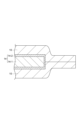
- FIG. 3 is a partial cross-sectional view of the terminal resin film and the metal terminal shown in FIG. 2 taken along the line AA.
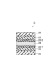
- FIG. 2 is a cross-sectional view schematically showing an example of the exterior material shown in FIG. 1
- FIG. 4 is a cross-sectional view schematically showing a terminal resin film according to another embodiment of the present disclosure
- FIG. 2 is a plan view showing a structure for obtaining evaluation samples in Examples and Comparative Examples;
- FIG. 1 is a cross-sectional view schematically showing a terminal resin film of an all-solid-state battery according to an embodiment of the present disclosure.
- a terminal resin film (hereinafter also simply referred to as “terminal resin film”) 10 of the all-solid-state battery of the present embodiment includes a first sealant layer 1, an insulating layer 2 and a second sealant layer 3. are prepared in this order. That is, the terminal resin film 10 is a multilayer film.
- the first sealant layer 1 is provided on the first surface 2 a side of the insulating layer 2
- the second sealant layer 3 is provided on the second surface 2 b side of the insulating layer 2 .
- the first sealant layer 1 and the second sealant layer 3 are provided on both sides of the insulating layer 2 .
- the moisture content of the terminal resin film 10 is 2700 ppm by mass or less.
- the terminal resin film 10 may have an adhesive layer for bonding the first sealant layer 1 and the insulating layer 2 together.
- the terminal resin film 10 may have an adhesive layer for bonding the second sealant layer 3 and the insulating layer 2 together.
- the terminal resin film 10 when the terminal resin film 10 is heat-sealed to the metal terminal, the number of air bubbles in the terminal resin film 10 is reduced compared to when the terminal resin film 10 has a moisture content of more than 2700 ppm by mass. Occurrence can be further suppressed.
- the terminal resin film 10 since the terminal resin film 10 is composed of a multilayer film including the insulating layer 2 and the first sealant layer 1 and the second sealant layer 3 provided on both sides of the insulating layer 2, the terminal resin film 10 functions It is possible to separate them. That is, the thickness of the terminal resin film 10 is ensured by the insulating layer 2, and the insulating property at the time of heat sealing is ensured.
- the first sealant layer 1 can fill the gap between the terminal resin film 10 and the metal terminal.
- the second sealant layer 3 can be heat-sealed (heat-sealed) to the exterior bag of the all-solid-state battery.
- the insulating layer 2 prevents the terminal resin film 10 from Since the thickness is guaranteed, stable insulation is ensured.
- the water content of the terminal resin film 10 may be 2700 mass ppm or less, but may be 2600 mass ppm or less, 2500 mass ppm or less, or 2200 mass ppm or less.
- the water content of the terminal resin film 10 is preferably 2000 mass ppm or less, more preferably 1500 mass ppm or less.
- the moisture content of the terminal resin film 10 may be 0 mass ppm.
- the moisture content of the terminal resin film 10 may be 200 mass ppm or more, 300 mass ppm or more, 400 mass ppm or more, or 500 mass ppm or more.
- each of the first sealant layer 1, the insulating layer 2, and the second sealant layer 3 may have a water content of 2700 mass ppm or less, but some layers have a water content of 2700 mass ppm or less and the remaining Even if the water content in the layer is higher than 2700 ppm by mass, the total water content should be 2700 ppm by mass or less.
- the first sealant layer 1 is a layer that is adhered to a portion of the outer peripheral surface of the metal terminal 14 by heat sealing (thermal fusion bonding).
- first sealant layer 1 examples include thermoplastic resins such as polyolefin resins, polyamide resins, polyester resins, polycarbonate resins, polyphenylene ether resins, polyacetal resins, polystyrene resins, polyvinyl chloride resins, and polyvinyl acetate resins.
- thermoplastic resins such as polyolefin resins, polyamide resins, polyester resins, polycarbonate resins, polyphenylene ether resins, polyacetal resins, polystyrene resins, polyvinyl chloride resins, and polyvinyl acetate resins.
- a film can be used. Sealing suitability and heat resistance can be controlled by blending the various resins listed above to form a polymer alloy.
- a film containing a polyolefin resin hereinafter also referred to as a "polyolefin film”
- a film containing a polyester resin hereinafter also referred to as a “polyester film”
- the sealing performance with respect to the metal terminal and the exterior bag is improved.
- the polyolefin film and the polyester film have heat resistance, the terminal resin film 10 can further improve the heat resistance of the all-solid-state battery.
- Polyolefin resins include, for example, low-density, medium-density or high-density polyethylene; ethylene- ⁇ -olefin copolymers; polypropylene; block or random copolymers containing propylene as a copolymerization component; Examples include polyolefin resins such as polymers.
- the polyolefin resin may be an acid-modified polyolefin resin obtained by modifying a polyolefin resin with acid or glycidyl.
- the first sealant layer 1 is preferably an acid-modified polyolefin resin layer containing an acid-modified polyolefin resin. In this case, since the acid-modified polyolefin resin layer has excellent adhesion to metal, the adhesion between the terminal resin film 10 and the metal terminal can be further improved.
- polyester resins examples include polyethylene terephthalate (PET) resin, polybutylene terephthalate (PBT) resin, polyethylene naphthalate (PEN) resin, polybutylene naphthalate (PBN) resin, and copolymers thereof. be done.
- PET polyethylene terephthalate
- PBT polybutylene terephthalate
- PEN polyethylene naphthalate
- PBN polybutylene naphthalate
- copolymers thereof be done.
- One of these polyester-based resins may be used alone, or two or more thereof may be used in combination. Copolymerization of any acid and glycol may also be used.
- the first sealant layer 1 contains, for example, an antioxidant, a slip agent, a flame retardant, an antiblocking agent, a light stabilizer, a dehydrating agent, a tackifier, and a crystal nucleus in order to impart sealability, heat resistance and other functionality. Additives such as agents and plasticizers may be further included as necessary.
- the melting point of the first sealant layer 1 is not particularly limited, it is preferably 150°C or higher, more preferably 155°C or higher, and even more preferably 160°C or higher. Since the melting point of the first sealant layer 1 is 150° C. or higher, even if the terminal resin film 10 is used in a high-temperature environment, it is possible to suppress a decrease in the sealing strength of the terminal resin film 10 against the metal terminals. .
- the all-solid-state battery contains a sulfide-based solid electrolyte as a solid electrolyte in the exterior bag, gas such as hydrogen sulfide is generated due to the reaction between the moisture and the sulfide-based solid electrolyte in the exterior bag of the all-solid-state battery. Even if it occurs, such gas leakage can be further suppressed.
- the melting point of the first sealant layer 1 is preferably 250°C or lower, more preferably 240°C or lower, and even more preferably 230°C or lower.
- the heat sealing temperature can be lowered by setting the melting point of the first sealant layer 1 to 250° C. or less. Therefore, when the terminal resin film 10 is heat-sealed to the metal terminal, the generation of air bubbles in the first sealant layer 1 can be further suppressed. Therefore, deterioration of the sealing strength and barrier properties of the terminal resin film 10 to the metal terminal is further suppressed. Therefore, the terminal resin film 10 can more sufficiently maintain the sealing performance of the exterior bag of the all-solid-state battery. In addition, the terminal resin film 10 can also suppress penetration of moisture through the terminal resin film 10 .
- the thickness of the first sealant layer 1 is not particularly limited, it is preferably 10-200 ⁇ m, more preferably 20-150 ⁇ m. When the thickness of the first sealant layer 1 is 10 ⁇ m or more, the gap between the metal terminal and the terminal resin film 10 is easily filled with the resin constituting the first sealant layer 1 . In addition, since the thickness of the first sealant layer 1 is 200 ⁇ m or less, the amount of heat required to melt the first sealant layer 1 can be reduced, so that the sealing of the terminal resin film 10 to the metal terminal is facilitated. It can be performed at a low temperature in a short time, shortening the tact time, and further improving productivity.
- the thickness of the first sealant layer 1 may be greater than the thickness of the second sealant layer 3 or less than the thickness of the second sealant layer 3, but is preferably greater than the thickness of the second sealant layer 3. .
- the thickness of the first sealant layer 1 is greater than the thickness of the second sealant layer 3 so that the terminal resin film 10 is heated to the metal terminal at a high temperature. Since the amount of resin filling the gap between the first sealant layer 1 and the metal terminal can be made larger than that of the second sealant layer 3 when sealing, the gap can be filled more easily.
- the first sealant layer 1 and the second sealant layer 3 have the same thickness, and the first sealant layer 1 and the second sealant layer 3 contain the same resin.
- the first sealant layer 1 can be used as the second sealant layer 3 and the second sealant layer 3 can be used as the first sealant layer 1, and the terminal resin film 10 can be fused to the metal terminal.
- the resin contained in the first sealant layer 1 and the second sealant layer 3 is preferably an acid-modified polyolefin resin. In this case, even when the second sealant layer 3 is heat-sealed to the metal terminal, the adhesion between the metal terminal and the terminal resin film is improved.
- the insulating layer 2 is a layer for suppressing thinning (seal thinning) of the terminal resin film 10 during heat sealing and ensuring insulation between the metal terminal and the metal layer of the exterior material.
- a film containing a thermoplastic resin such as polyolefin resin, polyamide resin, polyester resin, polycarbonate resin, polyphenylene ether resin, polyacetal resin, polystyrene resin, polyvinyl chloride resin, polyvinyl acetate resin, etc.
- a thermoplastic resin such as polyolefin resin, polyamide resin, polyester resin, polycarbonate resin, polyphenylene ether resin, polyacetal resin, polystyrene resin, polyvinyl chloride resin, polyvinyl acetate resin, etc.
- Sealing suitability and heat resistance can be controlled by blending the various resins listed above to form a polymer alloy.
- the terminal resin film 10 can further improve the heat resistance of the all-solid-state battery.
- the insulating layer 2 contains, for example, an antioxidant, a slip agent, a flame retardant, an antiblocking agent, a light stabilizer, a dehydrating agent, a tackifier, and a crystal nucleus in order to impart sealability, heat resistance, and other functionality.
- Additives such as agents, colorants, plasticizers, etc. may be further included as necessary.
- the melting point of the insulating layer 2 is not particularly limited, it is preferably 150°C or higher, more preferably 155°C or higher, and even more preferably 160°C or higher.
- the insulating layer 2 has a melting point of 150° C. or higher, it is possible to suppress deterioration in sealing strength of the terminal resin film 10 against metal terminals even when the terminal resin film 10 is used in a high-temperature environment. Therefore, when the all-solid-state battery contains a sulfide-based solid electrolyte as a solid electrolyte in the exterior bag, gas such as hydrogen sulfide is generated due to the reaction between the moisture and the sulfide-based solid electrolyte in the exterior bag of the all-solid-state battery. Even if it occurs, such gas leakage can be further suppressed.
- the melting point of the insulating layer 2 is preferably 250°C or lower, more preferably 240°C or lower, and even more preferably 230°C or lower.
- the melting point of the insulating layer 2 may be higher than the melting points of the resins contained in the first sealant layer 1 and the second sealant layer 3, and not higher than the melting points of the resins contained in the first sealant layer 1 and the second sealant layer 3. However, it is preferably higher than the melting points of the resins contained in the first sealant layer 1 and the second sealant layer.
- the terminal resin film 10 is heat-sealed with an exterior material including a barrier layer made of a metal layer, it is possible to suppress the seal thinning (thinning) of the insulating layer 2 , and the barrier layer of the exterior material and the metal terminal can be suppressed. It becomes easy to secure insulation between.
- the thickness of the insulating layer 2 is not particularly limited, it is preferably 10 to 200 ⁇ m, more preferably 20 to 150 ⁇ m. Sufficient insulation can be obtained by setting the thickness of the insulating layer 2 to 10 ⁇ m or more. By setting the thickness of the insulating layer 2 to 100 ⁇ m or less, it is possible to reduce the amount of water vapor that enters from the peripheral portion of the terminal resin film 10 .
- the second sealant layer 3 is a layer that is heat-sealed (heat-sealed) to the exterior bag of the all-solid-state battery.
- the second sealant layer 3 examples include thermoplastic resins such as polyolefin resins, polyamide resins, polyester resins, polycarbonate resins, polyphenylene ether resins, polyacetal resins, polystyrene resins, polyvinyl chloride resins, and polyvinyl acetate resins.
- thermoplastic resins such as polyolefin resins, polyamide resins, polyester resins, polycarbonate resins, polyphenylene ether resins, polyacetal resins, polystyrene resins, polyvinyl chloride resins, and polyvinyl acetate resins.
- a film can be used. Sealing suitability and heat resistance can be controlled by blending the various resins listed above to form a polymer alloy.
- the terminal resin film 10 can further improve the heat resistance of the all-solid-state battery.
- Polyolefin resins include, for example, low-density, medium-density or high-density polyethylene; ethylene- ⁇ -olefin copolymers; polypropylene; block or random copolymers containing propylene as a copolymerization component; Examples include polyolefin resins such as polymers.
- the polyolefin resin may be an acid-modified polyolefin resin obtained by modifying a polyolefin resin with acid or glycidyl.
- polyester resins examples include polyethylene terephthalate (PET) resin, polybutylene terephthalate (PBT) resin, polyethylene naphthalate (PEN) resin, polybutylene naphthalate (PBN) resin, and copolymers thereof. be done.
- PET polyethylene terephthalate
- PBT polybutylene terephthalate
- PEN polyethylene naphthalate
- PBN polybutylene naphthalate
- copolymers thereof be done.
- One of these polyester-based resins may be used alone, or two or more thereof may be used in combination. Copolymerization of any acid and glycol may also be used.
- the second sealant layer 3 is also composed of a polyolefin film.
- a laminated film composed of the first sealant layer 1, the insulating layer 2 and the second sealant layer 3 can be formed by co-extrusion, and the adhesion strength between the layers can be further increased.
- the first sealant layer 1 and the insulating layer 2 are made of a polyester film
- the second sealant layer 3 is also made of a polyester film. In this case, good adhesion can be obtained when the first sealant layer 1, the insulating layer 2 and the second sealant layer 3 are adhered with a heat-resistant polyester-based adhesive.
- the second sealant layer 3 contains, for example, an antioxidant, a slip agent, a flame retardant, an antiblocking agent, a light stabilizer, a dehydrating agent, a tackifier, a Additives such as crystal nucleating agents and plasticizers may be further included as necessary.
- the melting point of the second sealant layer 3 is not particularly limited, it is preferably 150°C or higher, more preferably 155°C or higher, and even more preferably 160°C or higher. Since the melting point of the second sealant layer 3 is 150° C. or higher, even when the terminal resin film 10 is used in a high-temperature environment, it is possible to suppress a decrease in the sealing strength of the terminal resin film 10 against the metal terminals. .
- the all-solid-state battery contains a sulfide-based solid electrolyte as a solid electrolyte in the exterior bag, gas such as hydrogen sulfide is generated due to the reaction between the moisture and the sulfide-based solid electrolyte in the exterior bag of the all-solid-state battery. Even if it occurs, such gas leakage can be further suppressed.
- the melting point of the second sealant layer 3 is preferably 250°C or lower, more preferably 240°C or lower, and even more preferably 230°C or lower.
- the heat sealing temperature can be lowered by setting the melting point of the second sealant layer 3 to 250° C. or lower. Therefore, when the terminal resin film 10 is heat-sealed to the exterior bag, the generation of air bubbles in the second sealant layer 2 can be further suppressed. Therefore, deterioration of the sealing strength and barrier properties of the terminal resin film 10 to the metal terminal is further suppressed. Therefore, the terminal resin film 10 can more sufficiently maintain the sealing performance of the exterior bag of the all-solid-state battery. In addition, the terminal resin film 10 can also suppress penetration of moisture through the terminal resin film 10 .
- the melting point of the second sealant layer 3 may be the same as or different from the melting point of the first sealant layer 1, but preferably the same.
- the thickness of the second sealant layer 3 is not particularly limited, it is preferably 10-200 ⁇ m, more preferably 20-150 ⁇ m. Sufficient sealing strength can be obtained by setting the thickness of the second sealant layer 3 to 10 ⁇ m or more. Since the thickness of the second sealant layer 3 is 200 ⁇ m or less, the amount of heat required to melt the second sealant layer 3 can be reduced. Sealing can be performed at a low temperature in a short time, shortening the tact time and further improving productivity.
- the terminal resin film 10 is used in an all-solid-state battery having a sulfide-based solid electrolyte
- at least one of the layers constituting the terminal resin film 10 of the present embodiment contains hydrogen sulfide that decomposes or adsorbs hydrogen sulfide. It may contain a decomposition adsorption material.
- the hydrogen sulfide decomposition and adsorption material is contained in, for example, the first sealant layer 1, the insulating layer 2, the second sealant layer 3, or the adhesive layer.
- Hydrogen sulfide decomposition and adsorption materials include zinc oxide, amorphous metal silicates (mainly containing copper and zinc as metals), hydrates of zirconium and tantanoid elements, and tetravalent metal phosphates (especially those containing metals).
- copper amorphous metal silicates (mainly containing copper and zinc as metals), hydrates of zirconium and tantanoid elements, and tetravalent metal phosphates (especially those containing metals).
- copper mixtures of zeolite and zinc ions, mixtures of zeolite, zinc oxide and copper(II) oxide, potassium permanganate, sodium permanganate, silver sulfate, silver acetate, aluminum oxide, iron hydroxide, Isocyanate compounds, aluminum silicate, potassium aluminum sulfate, zeolite, activated carbon, amine compounds, ionomers and the like.
- the hydrogen sulfide decomposition and adsorption material preferably contains zinc oxide (ZnO) and/or zinc ions from the viewpoints of making hydrogen sulfide more harmless and from the viewpoint of cost and handling.
- the hydrogen sulfide decomposition and adsorption material can be used alone or in combination of two or more.
- the hydrogen sulfide decomposition and adsorption material As the hydrogen sulfide decomposition and adsorption material, the following deodorant that has a deodorant effect on hydrogen sulfide may be used. Specifically, for example, Dainichi Seika Kogyo Co., Ltd.'s "Daime Shoe PE-M 3000-Z” (polyethylene masterbatch product), Toagosei Co., Ltd.'s “Kesmon”, Rasa Kogyo Co., Ltd.'s “Shokulens , and "Dashlight ZU” and "Dashlight CZU” manufactured by Sinanen Zeomic Co., Ltd.
- a metallic soap such as zinc stearate may be added to the layer containing the hydrogen sulfide decomposition and adsorption material from the viewpoint of improving the dispersibility of the hydrogen sulfide decomposition and adsorption material.
- the dispersibility of the hydrogen sulfide decomposition and adsorption material in the layer can be improved, and the effect of detoxifying hydrogen sulfide is less likely to occur. It is easy to suppress deterioration of the function (for example, adhesion strength, seal strength, etc.) of the layer containing the adsorbent material.
- the hydrogen sulfide decomposition/adsorption material may be used as a masterbatch in advance.
- a high-concentration blended product is prepared in advance as a masterbatch.
- the masterbatch may be blended with the resin of at least one of the first sealant layer 1, the insulating layer 2, the second sealant layer 3 and the adhesive layer so as to obtain an appropriate concentration.
- the hydrogen sulfide decomposition and adsorption material is preferably blended with the insulating layer 2 .
- the hydrogen sulfide decomposition and adsorption material is not blended in the first sealant layer 1 and the second sealant layer 3, it is possible to further suppress the decrease in the strength between the first sealant layer 1 of the terminal resin film and the metal terminal. , it is possible to further suppress the deterioration of the strength between the second sealant layer 3 of the terminal resin film and the exterior material.
- the hydrogen sulfide decomposition and adsorption material may be blended in the second sealant layer 3 . Even in this case, since the hydrogen sulfide decomposition and adsorption material is not mixed in the first sealant layer 1, it is possible to further suppress a decrease in the strength between the first sealant layer 1 of the terminal resin film and the metal terminal.
- the hydrogen sulfide decomposition and adsorption material when the adhesive layer is coated, it may be blended directly into the coating liquid, or when the adhesive layer is formed by extrusion or the like. may be blended by preparing a masterbatch in the same manner as the first sealant layer 1 .
- thermoplastic resins such as polyolefin resins, polyamide resins, polyester resins, polycarbonate resins, polyphenylene ether resins, polyacetal resins, polystyrene resins, polyvinyl chloride resins, and polyvinyl acetate resins can be used. Resin can be used.
- the content of the hydrogen sulfide decomposition and adsorption material in the layer containing the hydrogen sulfide decomposition and adsorption material may be 0.01% by mass or more and 30% by mass or less based on the total amount of the layer, and may be 0.05% by mass or more and 20% by mass. It may be less than or equal to 0.1% by mass or more and 15% by mass or less.
- the content of the hydrogen sulfide decomposition and adsorption material is at least the above lower limit value, the effect of detoxifying hydrogen sulfide can be sufficiently obtained, and when it is at most the above upper limit value, the layer containing the hydrogen sulfide decomposition and adsorption material is reduced. A decrease in functions (for example, adhesion strength, seal strength, etc.) can be suppressed.
- the terminal resin film 10 can be obtained, for example, by co-extrusion of the first sealant layer 1, the insulating layer 2 and the second sealant layer 3.
- the terminal resin film 10 can also be obtained by preparing the first sealant layer 1, the insulating layer 2, and the second sealant layer 3 in advance, laminating them, and thermally laminating them.
- the temperature during heat lamination may be higher than the melting point of the first sealant layer 1 and the melting point of the second sealant layer 3 .
- the terminal resin film 10 has the first sealant layer 1, the adhesive layer, the insulating layer 2, and the second sealant layer 3, the two-layer film consisting of the insulating layer 2 and the second sealant layer 3 is formed in advance.
- the two-layer film and the first sealant layer 1 may be laminated using an adhesive by a dry lamination method using an adhesive.
- the terminal resin film 10 and the metal terminal 14 are melt-bonded together by a fusion process. At this time, with the first sealant layer 1 of the terminal resin film 10 shown in FIG. The terminal resin film 10 and the metal terminal 14 are heat-sealed (see FIG. 3).
- the first sealant layer 1 In the fusion process, from the viewpoint of obtaining sufficient adhesiveness and sealing between the terminal resin film 10 and the metal terminal 14, it is preferable to heat the first sealant layer 1 to a temperature higher than the melting point of the first sealant layer 1 +20°C.
- the temperature for heating the terminal resin film 10 may be, for example, 155 to 285°C.
- the heat-sealing time can be determined in consideration of the adhesion to the metal terminal 14 and productivity.
- the heat-sealing time can be appropriately set, for example, within the range of 1 to 60 seconds.
- the terminal resin film 10 and the exterior material 13 are melt-bonded (see FIG. 2). Specifically, the terminal resin film 10 and the exterior material are heat-sealed while simultaneously melting the second sealant layer 3 by heating and adhering the second sealant layer 3 to the exterior material by pressure. .
- the heating temperature may be a temperature at which both the second sealant layer 3 of the terminal resin film 10 and the sealant layer of the exterior material 13 are melted.
- the melting point of the sealant layer having the higher melting point among the second sealant layer 3 of the terminal resin film 10 and the sealant layer of the exterior material 13 is +20°C. It is preferable to set the temperature as above.
- the temperature for heating the terminal resin film 10 may be, for example, 155 to 285°C.
- the heat-sealing time can be determined in consideration of adhesion to the exterior material 13 and productivity.
- the heat-sealing time can be appropriately set, for example, within the range of 1 to 60 seconds.
- FIG. 2 is a perspective view showing an embodiment of an all-solid-state battery produced using the terminal resin film described above.
- the all-solid-state battery 50 includes a battery body 11 having a sulfide-based electrolyte as a solid electrolyte, and two metal terminals (current extraction terminals) 14 for extracting current from the battery body 11 to the outside. , terminal resin film 10, and exterior bag 54 for housing battery body 11 in an airtight state.
- the exterior bag 54 is used as a container for housing the battery body 11 .
- the terminal resin film 10 is adhered to a part of the outer peripheral surface of the metal terminal 14 , and the metal terminal 14 is sandwiched by the exterior bag 54 with the terminal resin film 10 interposed therebetween.
- the first sealant layer 1 is adhered to the metal terminal 14 and the second sealant layer 3 is adhered to the exterior bag 54 .
- the terminal resin film 10 is adhered to the metal terminal 14 by heat sealing.
- the generation of air bubbles in the terminal resin film 10 can be suppressed. Therefore, according to the all-solid-state battery 50, it is possible to prevent the terminal resin film 10 from having a rough portion and a dense portion, resulting in a decrease in the sealing strength with respect to the metal terminal at the rough portion.
- the all-solid-state battery 50 is protected from the exterior bag 54 by the terminal resin film 10 .
- the leakage of the hydrogen sulfide from the exterior bag 54 is suppressed.
- the generation of air bubbles, which tend to become passages for moisture is suppressed, so that the intrusion of moisture from the outside of the terminal resin film 10 is suppressed.
- the battery main body 11, the metal terminals 14, and the exterior bag 54 will be described in detail below.
- the battery body 11 has at least one power generation element consisting of a positive electrode, a solid electrolyte and a negative electrode.
- the solid electrolyte is not limited to a sulfide-based solid electrolyte, and may be an oxide-based solid electrolyte or the like.
- ⁇ Metal terminal> As shown in FIGS. 2 and 3, the pair of metal terminals 14 has a metal terminal body 14-1 and a corrosion prevention layer 14-2. Of the pair of metal terminal bodies 14-1, one metal terminal body 14-1 is electrically connected to the positive electrode of the battery body 11, and the other metal terminal body 14-1 is connected to the negative electrode of the battery body 11. is electrically connected to The pair of metal terminal main bodies 14-1 extend in a direction away from the battery main body 11, and are partly exposed from the exterior material 13. As shown in FIG.
- the shape of the pair of metal terminal bodies 14-1 can be, for example, a flat plate shape.
- Metal can be used as the material for the metal terminal body 14-1. This metal can be determined in consideration of the structure of the battery body 11 and the material of each component of the battery body 11 .
- the material of the metal terminal main body 14-1 connected to the positive electrode of the battery main body 11 is preferably aluminum.
- the material of the metal terminal main body 14-1 connected to the positive electrode of the battery main body 11 may be an aluminum material with a purity of 97% or higher, such as 1N30.
- an O material that has been tempered by sufficient annealing may be used for the purpose of adding flexibility.
- the material of the metal terminal main body 14-1 connected to the negative electrode of the battery main body 11 can be composed of, for example, copper with a nickel plating layer formed on its surface, or nickel.
- the thickness of the metal terminal body 14-1 can be determined according to the size and capacity of the all-solid-state battery 50. If the all-solid-state battery 50 is small, the thickness of the metal terminal body 14-1 may be 50 ⁇ m or more. In the case of a large-sized all-solid-state battery for power storage, in-vehicle use, etc., the thickness of the metal terminal main body 14-1 can be appropriately set within the range of 100 to 1000 ⁇ m.
- the corrosion prevention layer 14-2 is arranged so as to cover the surface of the metal terminal body 14-1.
- the corrosion prevention layer 14-2 is a layer for suppressing corrosion of the metal terminal body 14-1 from corrosive components such as hydrogen sulfide.
- the exterior bag 54 is obtained by overlapping two exterior materials 13 and heat-sealing the overlapped peripheral edge portions.
- the exterior bag 54 can also be obtained by folding the exterior material 13 in half and heat-sealing the overlapped peripheral edges.
- the exterior material 13 includes, from the battery body 11 side, a sealant layer 21, a first adhesive layer 22, a corrosion prevention treatment layer 23-1, a barrier layer 24, a corrosion prevention treatment layer 23-2, and a second adhesive layer.
- An agent layer 25 and a substrate layer 26 are provided in this order (see FIG. 4).
- the sealant layer 21 is a layer that imparts sealing properties to the exterior material 13 by heat sealing, and is a layer that is arranged inside and heat-sealed (heat-sealed) when the all-solid-state battery 50 is assembled.
- a polyolefin resin or an acid-modified polyolefin resin obtained by graft-modifying a polyolefin resin with maleic anhydride or the like can be used.
- polystyrene resin low-density, medium-density and high-density polyethylene; ethylene- ⁇ -olefin copolymer; homo, block or random polypropylene; propylene- ⁇ -olefin copolymer and the like can be used.
- the polyolefin resin preferably contains polypropylene.
- the sealant layer 21 may be a single-layer film or a multi-layer film in which multiple layers are laminated, depending on the required functions. Specifically, it may be a multi-layer film in which a resin such as an ethylene-cyclic olefin copolymer or polymethylpentene is interposed in order to impart moisture resistance.
- the sealant layer 21 may contain various additives (flame retardants, slip agents, antiblocking agents, antioxidants, light stabilizers, tackifiers, etc.).
- the thickness of the sealant layer 21 is preferably 10-150 ⁇ m, more preferably 30-80 ⁇ m.
- the thickness of the sealant layer 21 is 10 ⁇ m or more, the exterior material 13 can have sufficient adhesion to the exterior material 13 or the terminal resin film 10 .
- the thickness of the sealant layer 21 is 150 ⁇ m or less, the cost of the exterior material 13 can be suppressed.
- a known adhesive such as a dry lamination adhesive or an acid-modified heat-sealable resin can be appropriately selected and used.
- the corrosion prevention treatment layers 23-1 and 23-2 are preferably formed on both sides of the barrier layer 24 in terms of performance.
- the corrosion prevention treatment layer 23-1 may be arranged only on the surface of the barrier layer 24 that is to be exposed.
- the barrier layer 24 may be a conductive metal layer.
- materials for the barrier layer 24 include aluminum and stainless steel, and aluminum is preferable from the viewpoint of cost, mass (density), and the like.
- a polyurethane-based adhesive containing polyester polyol, polyether polyol, acrylic polyol, or the like as a main ingredient can be used.
- the base material layer 26 may be a single layer film such as nylon or polyethylene terephthalate (PET), or a multilayer film. Like the sealant layer 21, the base material layer 26 may contain various additives (flame retardants, slip agents, antiblocking agents, antioxidants, light stabilizers, tackifiers, etc.).
- the exterior material 13 may further include a protective layer (not shown) for protecting the base material layer 26 on the surface of the base material layer 26 opposite to the sealant layer 21 .
- an adhesive resin layer may be used.
- At least one layer among the layers constituting the exterior material 13 of the present embodiment may contain a hydrogen sulfide decomposition and adsorption material, similar to the terminal resin film 10 .
- a hydrogen sulfide decomposition and adsorption material similar to the terminal resin film 10 .
- the hydrogen sulfide decomposition and adsorption material is contained in, for example, the first adhesive layer 22, the second adhesive layer 25, the sealant layer 21, or at least one layer of these.
- the hydrogen sulfide decomposition and adsorption material is preferably contained in the sealant layer 21 . In this case, permeation of hydrogen sulfide through the exterior material 13 is effectively suppressed.
- the terminal resin film 10 includes the first sealant layer 1, the insulating layer 2, and the second sealant layer 3.
- the terminal resin film 10 is It is not necessary to have the insulating layer 2 .
- the terminal resin film may be composed of a single layer film like the terminal resin film 110 shown in FIG. In this case, the terminal resin film 110 has a moisture content of 2700 ppm by mass or less.
- the terminal resin film 110 may be composed of either the first sealant layer 1 , the insulating layer 2 or the second sealant layer 3 .
- Example 1 A film made of acid-modified polypropylene (thickness: 25 ⁇ m, melting point: 140° C.), a film made of polypropylene (thickness: 50 ⁇ m, melting point: 164° C.), and a film made of acid-modified polypropylene (thickness: 25 ⁇ m, melting point: 140° C.) were coextruded to obtain a polyolefin film 1 (PO film 1) having a thickness of 100 ⁇ m. The water content of the obtained PO film 1 was 358 mass ppm.
- Example 2 PO film 1 was changed to polyolefin film 2 (PO film 2) made of polypropylene-polyethylene random copolymer (manufactured by Futamura Chemical Co., Ltd., trade name: FHK2, melting point: 135° C.), and the thickness was changed from 100 ⁇ m to 40 ⁇ m.
- a resin film for a terminal was obtained in the same manner as in Example 1 except for the above. The moisture content of the obtained terminal resin film was 516 mass ppm.
- Example 3 Example except that the PO film 1 was changed to a polyester film (polyester film 1) made of polyethylene terephthalate (manufactured by Unitika Ltd., trade name: Emblet, melting point: 257° C.) and the thickness was changed from 100 ⁇ m to 25 ⁇ m.
- a terminal resin film was obtained in the same manner as in Example 1. The moisture content of the obtained terminal resin film was 2682 mass ppm.
- Example 4 Example except that the PO film 1 was changed to a polyester film (polyester film 2) made of polyethylene naphthalate (manufactured by Toyobo Co., Ltd., trade name: Teonex, melting point: 265° C.) and the thickness was changed from 100 ⁇ m to 25 ⁇ m.
- a terminal resin film was obtained in the same manner as in Example 1. The moisture content of the obtained terminal resin film was 2637 mass ppm.
- Example 5 Example 1 was repeated except that the PO film 1 was changed to a polyester film (polyester film 3) made of a copolymer of multiple types of polyethylene terephthalate (melting point: 210°C) and the thickness was changed from 100 ⁇ m to 25 ⁇ m. A terminal resin film was obtained. The moisture content of the obtained terminal resin film was 1648 mass ppm.
- polyester film 3 made of a copolymer of multiple types of polyethylene terephthalate (melting point: 210°C) and the thickness was changed from 100 ⁇ m to 25 ⁇ m.
- a terminal resin film was obtained.
- the moisture content of the obtained terminal resin film was 1648 mass ppm.
- the PO film 1 was a film made of acid-modified polypropylene (thickness: 25 ⁇ m, melting point: 165° C.), a film made of polypropylene (thickness: 50 ⁇ m, melting point: 165° C.), and a film made of acid-modified polypropylene (thickness: 25 ⁇ m, melting point: 165° C.).
- a terminal resin film was obtained in the same manner as in Example 1, except that the polyolefin film 3 (PO film 3) was changed to a laminate formed by co-extrusion. The moisture content of the obtained terminal resin film was 546 mass ppm.
- Example 1 Example 1 except that the PO film 1 was changed to a polyamide film (PA film) made of nylon 6 (manufactured by Toyobo Co., Ltd., trade name: Harden N1102, melting point: 225° C.), and the thickness was changed from 100 ⁇ m to 25 ⁇ m.
- a terminal resin film was obtained in the same manner as in the above.
- the moisture content of the obtained terminal resin film was 23729 mass ppm.
- the moisture content was measured as follows. That is, a terminal resin film cut into 10 cm squares was left in an environment of 23 ° C. / 50% RH for two days, and then a heating moisture vaporizer set at 300 ° C.
- Moisture content (mass ppm) measured moisture content (g) / mass of terminal resin film (g)
- a terminal resin film was cut into a size of 120 mm ⁇ 60 mm, folded in half, and both ends of the terminal resin film were overlapped in the longitudinal direction.
- the film was heat-sealed for 10 seconds at a temperature of +20° C. to the melting point of the film to form a heat-sealed portion having a width of 10 mm (hatched portion in FIG. 6), thereby producing a structure.
- the structure was then stored at room temperature for 12 hours. After that, a central portion of the heat-sealed portion in the longitudinal direction was cut out from the structure with a width of 15 mm ⁇ 30 mm (see the broken line portion in FIG. 6) to prepare an evaluation sample.
- this evaluation sample was separated into two separate pieces at the fused portion. Then, the fused portion of the separated pieces was visually observed, and the state of occurrence of air bubbles in the terminal resin film was evaluated based on the following criteria. Table 1 shows the results.
- the "melting point of the terminal resin film" is the outermost sealant layer having the lowest melting point among the layers constituting the multi-layer film. melting point. (Evaluation criteria) ⁇ : no bubbles are observed ⁇ : bubbles are observed locally ⁇ : bubbles are observed on the entire surface
- the resin film for terminals of the all-solid-state battery of the present disclosure can suppress the generation of air bubbles when heat-sealed to metal terminals.
- SYMBOLS 1 First sealant layer (sealant layer), 2... Insulating layer, 3... Second sealant layer (sealant layer), 10, 110... Resin film for terminal, 11... Battery body, 14... Metal terminal, 50... All solid battery.
Landscapes
- Chemical & Material Sciences (AREA)
- Chemical Kinetics & Catalysis (AREA)
- Electrochemistry (AREA)
- General Chemical & Material Sciences (AREA)
- Manufacturing & Machinery (AREA)
- Engineering & Computer Science (AREA)
- Inorganic Chemistry (AREA)
- Physics & Mathematics (AREA)
- Condensed Matter Physics & Semiconductors (AREA)
- General Physics & Mathematics (AREA)
- Sealing Battery Cases Or Jackets (AREA)
- Secondary Cells (AREA)
- Connection Of Batteries Or Terminals (AREA)
Priority Applications (4)
| Application Number | Priority Date | Filing Date | Title |
|---|---|---|---|
| KR1020247025611A KR20240140087A (ko) | 2022-02-02 | 2023-02-01 | 전고체 전지의 단자용 수지 필름 및 전고체 전지 |
| EP23749799.5A EP4475300A4 (en) | 2022-02-02 | 2023-02-01 | ALL-SOLID-STATE BATTERY TERMINAL RESIN FILM AND ALL-SOLID-STATE BATTERY |
| CN202380018535.9A CN118591932A (zh) | 2022-02-02 | 2023-02-01 | 全固态电池的端子用树脂膜以及全固态电池 |
| US18/791,273 US20240396136A1 (en) | 2022-02-02 | 2024-07-31 | Terminal resin film of fully-solid-state battery and fully-solid state battery |
Applications Claiming Priority (2)
| Application Number | Priority Date | Filing Date | Title |
|---|---|---|---|
| JP2022-015008 | 2022-02-02 | ||
| JP2022015008A JP7556366B2 (ja) | 2022-02-02 | 2022-02-02 | 全固体電池の端子用樹脂フィルム及び全固体電池 |
Related Child Applications (1)
| Application Number | Title | Priority Date | Filing Date |
|---|---|---|---|
| US18/791,273 Continuation US20240396136A1 (en) | 2022-02-02 | 2024-07-31 | Terminal resin film of fully-solid-state battery and fully-solid state battery |
Publications (1)
| Publication Number | Publication Date |
|---|---|
| WO2023149483A1 true WO2023149483A1 (ja) | 2023-08-10 |
Family
ID=87552434
Family Applications (1)
| Application Number | Title | Priority Date | Filing Date |
|---|---|---|---|
| PCT/JP2023/003260 Ceased WO2023149483A1 (ja) | 2022-02-02 | 2023-02-01 | 全固体電池の端子用樹脂フィルム及び全固体電池 |
Country Status (6)
| Country | Link |
|---|---|
| US (1) | US20240396136A1 (https=) |
| EP (1) | EP4475300A4 (https=) |
| JP (3) | JP7556366B2 (https=) |
| KR (1) | KR20240140087A (https=) |
| CN (1) | CN118591932A (https=) |
| WO (1) | WO2023149483A1 (https=) |
Citations (4)
| Publication number | Priority date | Publication date | Assignee | Title |
|---|---|---|---|---|
| JP2009032539A (ja) * | 2007-07-27 | 2009-02-12 | Toyota Motor Corp | 固体型電池 |
| JP2012178256A (ja) * | 2011-02-25 | 2012-09-13 | Toyota Motor Corp | イオン伝導体材料、固体電解質層、電極活物質層および全固体電池 |
| JP2016062712A (ja) * | 2014-09-17 | 2016-04-25 | トヨタ自動車株式会社 | 全固体リチウム二次電池の製造方法 |
| JP2021108242A (ja) * | 2019-12-27 | 2021-07-29 | 凸版印刷株式会社 | 端子用樹脂フィルム及びその選定方法、並びに蓄電装置 |
Family Cites Families (9)
| Publication number | Priority date | Publication date | Assignee | Title |
|---|---|---|---|---|
| DE69716324T2 (de) * | 1996-03-25 | 2003-06-18 | Toyo Boseki K.K., Osaka | Film zum Beschichten von Metall, laminiertes Metall sowie Metallbehälter |
| JP2001062974A (ja) | 1999-08-26 | 2001-03-13 | Mitsubishi Polyester Film Copp | 熱ラミネート用多層ポリエステルフィルム |
| JP2018170071A (ja) | 2017-03-29 | 2018-11-01 | マクセルホールディングス株式会社 | 電気化学素子 |
| JP7415921B2 (ja) | 2018-06-27 | 2024-01-17 | Toppanホールディングス株式会社 | 端子用樹脂フィルム及びこれを用いた蓄電装置 |
| US20220263377A1 (en) | 2019-08-21 | 2022-08-18 | Makita Corporation | Electric work machine |
| WO2021090951A1 (ja) | 2019-11-08 | 2021-05-14 | 大日本印刷株式会社 | 金属端子用接着性フィルム、金属端子用接着性フィルムの製造方法、金属端子用接着性フィルム付き金属端子、当該金属端子用接着性フィルムを用いた蓄電デバイス、及び蓄電デバイスの製造方法 |
| JP7585617B2 (ja) | 2020-03-25 | 2024-11-19 | Toppanホールディングス株式会社 | 蓄電デバイス用端子フィルム |
| JP7508915B2 (ja) * | 2020-07-16 | 2024-07-02 | 大日本印刷株式会社 | 金属端子用接着性フィルム、金属端子用接着性フィルム付き金属端子、接着性フィルム付き金属端子、当該金属端子用接着性フィルムを用いた接着性フィルム付き金属端子の製造方法、当該金属端子用接着性フィルムを用いた蓄電デバイス、及び蓄電デバイスの製造方法 |
| KR20230037490A (ko) | 2020-07-16 | 2023-03-16 | 다이니폰 인사츠 가부시키가이샤 | 전고체 전지의 금속 단자용 접착성 필름, 금속 단자용 접착성 필름 부착 금속 단자, 상기 금속 단자용 접착성 필름을 사용한 전고체 전지, 및 전고체 전지의 제조 방법 |
-
2022
- 2022-02-02 JP JP2022015008A patent/JP7556366B2/ja active Active
-
2023
- 2023-02-01 CN CN202380018535.9A patent/CN118591932A/zh active Pending
- 2023-02-01 EP EP23749799.5A patent/EP4475300A4/en active Pending
- 2023-02-01 KR KR1020247025611A patent/KR20240140087A/ko active Pending
- 2023-02-01 WO PCT/JP2023/003260 patent/WO2023149483A1/ja not_active Ceased
-
2024
- 2024-07-31 US US18/791,273 patent/US20240396136A1/en active Pending
- 2024-09-09 JP JP2024155302A patent/JP7761100B2/ja active Active
-
2025
- 2025-10-15 JP JP2025173766A patent/JP2025185191A/ja active Pending
Patent Citations (4)
| Publication number | Priority date | Publication date | Assignee | Title |
|---|---|---|---|---|
| JP2009032539A (ja) * | 2007-07-27 | 2009-02-12 | Toyota Motor Corp | 固体型電池 |
| JP2012178256A (ja) * | 2011-02-25 | 2012-09-13 | Toyota Motor Corp | イオン伝導体材料、固体電解質層、電極活物質層および全固体電池 |
| JP2016062712A (ja) * | 2014-09-17 | 2016-04-25 | トヨタ自動車株式会社 | 全固体リチウム二次電池の製造方法 |
| JP2021108242A (ja) * | 2019-12-27 | 2021-07-29 | 凸版印刷株式会社 | 端子用樹脂フィルム及びその選定方法、並びに蓄電装置 |
Non-Patent Citations (1)
| Title |
|---|
| See also references of EP4475300A4 * |
Also Published As
| Publication number | Publication date |
|---|---|
| JP2024161285A (ja) | 2024-11-15 |
| EP4475300A4 (en) | 2025-08-13 |
| EP4475300A1 (en) | 2024-12-11 |
| JP7556366B2 (ja) | 2024-09-26 |
| JP2025185191A (ja) | 2025-12-18 |
| KR20240140087A (ko) | 2024-09-24 |
| JP7761100B2 (ja) | 2025-10-28 |
| JP2023112961A (ja) | 2023-08-15 |
| US20240396136A1 (en) | 2024-11-28 |
| CN118591932A (zh) | 2024-09-03 |
Similar Documents
| Publication | Publication Date | Title |
|---|---|---|
| KR102507154B1 (ko) | 이차 전지용 단자 피복 수지 필름, 이차 전지용 탭 부재, 및 이차 전지 | |
| JP6699105B2 (ja) | 端子用樹脂フィルム、それを用いたタブ及び蓄電デバイス | |
| CN102969463A (zh) | 电池用包装材料及锂二次电池 | |
| JP6597027B2 (ja) | 電池、及び電池素子を収容するための包装材料 | |
| JP7676754B2 (ja) | 端子用樹脂フィルム、及びそれを用いた蓄電デバイス | |
| KR20210021942A (ko) | 축전 장치용 외장재 및 이것을 사용한 축전 장치 | |
| JP7001279B2 (ja) | 安全性が向上したパウチ型二次電池ケース | |
| US20240387911A1 (en) | Fully-solid-state battery packaging material and fully-solid-state battery | |
| JP2026021635A (ja) | タブシーラント及びこれを用いた蓄電デバイス | |
| JP2003051291A (ja) | 電池用包装材料およびそれを用いた電池 | |
| JP2026012902A (ja) | 端子用樹脂フィルム、及びそれを用いた蓄電デバイス | |
| WO2023149483A1 (ja) | 全固体電池の端子用樹脂フィルム及び全固体電池 | |
| KR101975305B1 (ko) | 안전성이 향상된 파우치형 이차전지 케이스 | |
| US20250132409A1 (en) | Protection film for all-solid-state battery | |
| WO2020262668A1 (ja) | 真空断熱材用外包材、真空断熱材、および真空断熱材付き物品 | |
| KR20250098760A (ko) | 파우치형 이차전지 및 파우치형 이차전지의 제조방법 | |
| WO2026014352A1 (ja) | 端子用樹脂フィルム、端子用樹脂フィルムの製造方法、及び蓄電デバイス | |
| CN117121245A (zh) | 蓄电器件用树脂膜和蓄电器件 | |
| CN120604383A (zh) | 软包膜层叠体和软包型二次电池 | |
| JP2022165772A (ja) | 端子用樹脂フィルム、及びそれを用いた蓄電デバイス |
Legal Events
| Date | Code | Title | Description |
|---|---|---|---|
| 121 | Ep: the epo has been informed by wipo that ep was designated in this application |
Ref document number: 23749799 Country of ref document: EP Kind code of ref document: A1 |
|
| WWE | Wipo information: entry into national phase |
Ref document number: 202380018535.9 Country of ref document: CN |
|
| ENP | Entry into the national phase |
Ref document number: 20247025611 Country of ref document: KR Kind code of ref document: A |
|
| WWE | Wipo information: entry into national phase |
Ref document number: 2023749799 Country of ref document: EP |
|
| NENP | Non-entry into the national phase |
Ref country code: DE |
|
| ENP | Entry into the national phase |
Ref document number: 2023749799 Country of ref document: EP Effective date: 20240902 |