WO2023149483A1 - Terminal resin film of all solid state battery and all solid state battery - Google Patents
Terminal resin film of all solid state battery and all solid state battery Download PDFInfo
- Publication number
- WO2023149483A1 WO2023149483A1 PCT/JP2023/003260 JP2023003260W WO2023149483A1 WO 2023149483 A1 WO2023149483 A1 WO 2023149483A1 JP 2023003260 W JP2023003260 W JP 2023003260W WO 2023149483 A1 WO2023149483 A1 WO 2023149483A1
- Authority
- WO
- WIPO (PCT)
- Prior art keywords
- resin film
- terminal
- solid
- state battery
- sealant layer
- Prior art date
Links
- 229920005989 resin Polymers 0.000 title claims abstract description 240
- 239000011347 resin Substances 0.000 title claims abstract description 240
- 239000007787 solid Substances 0.000 title abstract description 7
- 239000000565 sealant Substances 0.000 claims abstract description 154
- 229910052751 metal Inorganic materials 0.000 claims abstract description 95
- 239000002184 metal Substances 0.000 claims abstract description 95
- 230000002093 peripheral effect Effects 0.000 claims abstract description 13
- 238000002844 melting Methods 0.000 claims description 53
- 230000008018 melting Effects 0.000 claims description 53
- 238000007789 sealing Methods 0.000 claims description 46
- 239000007784 solid electrolyte Substances 0.000 claims description 34
- 229920005672 polyolefin resin Polymers 0.000 claims description 30
- UCKMPCXJQFINFW-UHFFFAOYSA-N Sulphide Chemical compound [S-2] UCKMPCXJQFINFW-UHFFFAOYSA-N 0.000 claims description 20
- XLYOFNOQVPJJNP-UHFFFAOYSA-N water Substances O XLYOFNOQVPJJNP-UHFFFAOYSA-N 0.000 claims description 19
- 229920006267 polyester film Polymers 0.000 claims description 17
- 229920000098 polyolefin Polymers 0.000 claims description 14
- 229920001225 polyester resin Polymers 0.000 claims description 11
- 239000004645 polyester resin Substances 0.000 claims description 9
- 238000009413 insulation Methods 0.000 abstract description 10
- 239000010410 layer Substances 0.000 description 252
- 239000000463 material Substances 0.000 description 66
- RWSOTUBLDIXVET-UHFFFAOYSA-N Dihydrogen sulfide Chemical compound S RWSOTUBLDIXVET-UHFFFAOYSA-N 0.000 description 45
- 229910000037 hydrogen sulfide Inorganic materials 0.000 description 45
- 238000000354 decomposition reaction Methods 0.000 description 25
- 238000001179 sorption measurement Methods 0.000 description 25
- -1 polypropylene Polymers 0.000 description 24
- 239000012790 adhesive layer Substances 0.000 description 16
- 239000007789 gas Substances 0.000 description 11
- 239000004743 Polypropylene Substances 0.000 description 10
- 230000004888 barrier function Effects 0.000 description 10
- 229920001155 polypropylene Polymers 0.000 description 10
- 239000003795 chemical substances by application Substances 0.000 description 8
- 229920000139 polyethylene terephthalate Polymers 0.000 description 8
- 239000005020 polyethylene terephthalate Substances 0.000 description 8
- 238000006243 chemical reaction Methods 0.000 description 7
- 238000005536 corrosion prevention Methods 0.000 description 7
- 230000006866 deterioration Effects 0.000 description 7
- 239000004594 Masterbatch (MB) Substances 0.000 description 6
- 239000000853 adhesive Substances 0.000 description 6
- 230000001070 adhesive effect Effects 0.000 description 6
- 229920005992 thermoplastic resin Polymers 0.000 description 6
- 229920000089 Cyclic olefin copolymer Polymers 0.000 description 5
- XLOMVQKBTHCTTD-UHFFFAOYSA-N Zinc monoxide Chemical compound [Zn]=O XLOMVQKBTHCTTD-UHFFFAOYSA-N 0.000 description 5
- 239000000654 additive Substances 0.000 description 5
- 229910052782 aluminium Inorganic materials 0.000 description 5
- XAGFODPZIPBFFR-UHFFFAOYSA-N aluminium Chemical compound [Al] XAGFODPZIPBFFR-UHFFFAOYSA-N 0.000 description 5
- 239000003963 antioxidant agent Substances 0.000 description 5
- 238000011156 evaluation Methods 0.000 description 5
- 239000003063 flame retardant Substances 0.000 description 5
- 238000010438 heat treatment Methods 0.000 description 5
- 239000004611 light stabiliser Substances 0.000 description 5
- 238000000034 method Methods 0.000 description 5
- 229920000642 polymer Polymers 0.000 description 5
- 239000012748 slip agent Substances 0.000 description 5
- RYGMFSIKBFXOCR-UHFFFAOYSA-N Copper Chemical compound [Cu] RYGMFSIKBFXOCR-UHFFFAOYSA-N 0.000 description 4
- LYCAIKOWRPUZTN-UHFFFAOYSA-N Ethylene glycol Chemical compound OCCO LYCAIKOWRPUZTN-UHFFFAOYSA-N 0.000 description 4
- PXHVJJICTQNCMI-UHFFFAOYSA-N Nickel Chemical compound [Ni] PXHVJJICTQNCMI-UHFFFAOYSA-N 0.000 description 4
- 229930182556 Polyacetal Natural products 0.000 description 4
- 239000002253 acid Substances 0.000 description 4
- 238000007334 copolymerization reaction Methods 0.000 description 4
- 229910052802 copper Inorganic materials 0.000 description 4
- 239000010949 copper Substances 0.000 description 4
- 238000001125 extrusion Methods 0.000 description 4
- 238000004519 manufacturing process Methods 0.000 description 4
- 229920006122 polyamide resin Polymers 0.000 description 4
- 229920001707 polybutylene terephthalate Polymers 0.000 description 4
- 229920005668 polycarbonate resin Polymers 0.000 description 4
- 239000004431 polycarbonate resin Substances 0.000 description 4
- 229920006324 polyoxymethylene Polymers 0.000 description 4
- 229920001955 polyphenylene ether Polymers 0.000 description 4
- 229920005990 polystyrene resin Polymers 0.000 description 4
- 229920002689 polyvinyl acetate Polymers 0.000 description 4
- 239000011118 polyvinyl acetate Substances 0.000 description 4
- 239000004800 polyvinyl chloride Substances 0.000 description 4
- 229920000915 polyvinyl chloride Polymers 0.000 description 4
- 239000004711 α-olefin Substances 0.000 description 4
- RNFJDJUURJAICM-UHFFFAOYSA-N 2,2,4,4,6,6-hexaphenoxy-1,3,5-triaza-2$l^{5},4$l^{5},6$l^{5}-triphosphacyclohexa-1,3,5-triene Chemical compound N=1P(OC=2C=CC=CC=2)(OC=2C=CC=CC=2)=NP(OC=2C=CC=CC=2)(OC=2C=CC=CC=2)=NP=1(OC=1C=CC=CC=1)OC1=CC=CC=C1 RNFJDJUURJAICM-UHFFFAOYSA-N 0.000 description 3
- QPLDLSVMHZLSFG-UHFFFAOYSA-N Copper oxide Chemical compound [Cu]=O QPLDLSVMHZLSFG-UHFFFAOYSA-N 0.000 description 3
- HBBGRARXTFLTSG-UHFFFAOYSA-N Lithium ion Chemical compound [Li+] HBBGRARXTFLTSG-UHFFFAOYSA-N 0.000 description 3
- 229910021536 Zeolite Inorganic materials 0.000 description 3
- 239000000956 alloy Substances 0.000 description 3
- 229910045601 alloy Inorganic materials 0.000 description 3
- 230000003078 antioxidant effect Effects 0.000 description 3
- 230000000052 comparative effect Effects 0.000 description 3
- 229920001577 copolymer Polymers 0.000 description 3
- 239000012024 dehydrating agents Substances 0.000 description 3
- HNPSIPDUKPIQMN-UHFFFAOYSA-N dioxosilane;oxo(oxoalumanyloxy)alumane Chemical compound O=[Si]=O.O=[Al]O[Al]=O HNPSIPDUKPIQMN-UHFFFAOYSA-N 0.000 description 3
- 230000000694 effects Effects 0.000 description 3
- 239000003792 electrolyte Substances 0.000 description 3
- 230000004927 fusion Effects 0.000 description 3
- 238000007499 fusion processing Methods 0.000 description 3
- 229920001903 high density polyethylene Polymers 0.000 description 3
- 239000004700 high-density polyethylene Substances 0.000 description 3
- 229910001416 lithium ion Inorganic materials 0.000 description 3
- 229920001684 low density polyethylene Polymers 0.000 description 3
- 239000004702 low-density polyethylene Substances 0.000 description 3
- 229920001179 medium density polyethylene Polymers 0.000 description 3
- 239000004701 medium-density polyethylene Substances 0.000 description 3
- 238000002156 mixing Methods 0.000 description 3
- 230000035515 penetration Effects 0.000 description 3
- 239000004014 plasticizer Substances 0.000 description 3
- 239000011112 polyethylene naphthalate Substances 0.000 description 3
- 229920005604 random copolymer Polymers 0.000 description 3
- 239000002356 single layer Substances 0.000 description 3
- 239000010457 zeolite Substances 0.000 description 3
- OKTJSMMVPCPJKN-UHFFFAOYSA-N Carbon Chemical compound [C] OKTJSMMVPCPJKN-UHFFFAOYSA-N 0.000 description 2
- 239000004698 Polyethylene Substances 0.000 description 2
- PTFCDOFLOPIGGS-UHFFFAOYSA-N Zinc dication Chemical compound [Zn+2] PTFCDOFLOPIGGS-UHFFFAOYSA-N 0.000 description 2
- 229920001400 block copolymer Polymers 0.000 description 2
- 239000013078 crystal Substances 0.000 description 2
- 239000002781 deodorant agent Substances 0.000 description 2
- 238000009820 dry lamination Methods 0.000 description 2
- 125000003055 glycidyl group Chemical group C(C1CO1)* 0.000 description 2
- WGCNASOHLSPBMP-UHFFFAOYSA-N hydroxyacetaldehyde Natural products OCC=O WGCNASOHLSPBMP-UHFFFAOYSA-N 0.000 description 2
- 238000010030 laminating Methods 0.000 description 2
- 150000002739 metals Chemical class 0.000 description 2
- 239000000203 mixture Substances 0.000 description 2
- 229910052759 nickel Inorganic materials 0.000 description 2
- 229920000573 polyethylene Polymers 0.000 description 2
- 229920005862 polyol Polymers 0.000 description 2
- QQONPFPTGQHPMA-UHFFFAOYSA-N propylene Natural products CC=C QQONPFPTGQHPMA-UHFFFAOYSA-N 0.000 description 2
- 125000004805 propylene group Chemical group [H]C([H])([H])C([H])([*:1])C([H])([H])[*:2] 0.000 description 2
- 239000011342 resin composition Substances 0.000 description 2
- 238000004904 shortening Methods 0.000 description 2
- 239000000344 soap Substances 0.000 description 2
- 239000011787 zinc oxide Substances 0.000 description 2
- JYLNVJYYQQXNEK-UHFFFAOYSA-N 3-amino-2-(4-chlorophenyl)-1-propanesulfonic acid Chemical compound OS(=O)(=O)CC(CN)C1=CC=C(Cl)C=C1 JYLNVJYYQQXNEK-UHFFFAOYSA-N 0.000 description 1
- 239000004713 Cyclic olefin copolymer Substances 0.000 description 1
- 239000004677 Nylon Substances 0.000 description 1
- 229920002292 Nylon 6 Polymers 0.000 description 1
- 239000004952 Polyamide Substances 0.000 description 1
- 239000004721 Polyphenylene oxide Substances 0.000 description 1
- HCHKCACWOHOZIP-UHFFFAOYSA-N Zinc Chemical compound [Zn] HCHKCACWOHOZIP-UHFFFAOYSA-N 0.000 description 1
- QCWXUUIWCKQGHC-UHFFFAOYSA-N Zirconium Chemical compound [Zr] QCWXUUIWCKQGHC-UHFFFAOYSA-N 0.000 description 1
- YKTSYUJCYHOUJP-UHFFFAOYSA-N [O--].[Al+3].[Al+3].[O-][Si]([O-])([O-])[O-] Chemical compound [O--].[Al+3].[Al+3].[O-][Si]([O-])([O-])[O-] YKTSYUJCYHOUJP-UHFFFAOYSA-N 0.000 description 1
- 239000004840 adhesive resin Substances 0.000 description 1
- 229920006223 adhesive resin Polymers 0.000 description 1
- 239000003463 adsorbent Substances 0.000 description 1
- 238000000137 annealing Methods 0.000 description 1
- 238000005452 bending Methods 0.000 description 1
- 239000012159 carrier gas Substances 0.000 description 1
- 239000011248 coating agent Substances 0.000 description 1
- 238000000576 coating method Methods 0.000 description 1
- 239000003086 colorant Substances 0.000 description 1
- 230000007797 corrosion Effects 0.000 description 1
- 238000005260 corrosion Methods 0.000 description 1
- 239000003484 crystal nucleating agent Substances 0.000 description 1
- 238000000605 extraction Methods 0.000 description 1
- 238000011049 filling Methods 0.000 description 1
- 150000004677 hydrates Chemical class 0.000 description 1
- 229920000554 ionomer Polymers 0.000 description 1
- 235000014413 iron hydroxide Nutrition 0.000 description 1
- NCNCGGDMXMBVIA-UHFFFAOYSA-L iron(ii) hydroxide Chemical compound [OH-].[OH-].[Fe+2] NCNCGGDMXMBVIA-UHFFFAOYSA-L 0.000 description 1
- 239000012948 isocyanate Substances 0.000 description 1
- 238000003475 lamination Methods 0.000 description 1
- 239000007788 liquid Substances 0.000 description 1
- 239000002075 main ingredient Substances 0.000 description 1
- FPYJFEHAWHCUMM-UHFFFAOYSA-N maleic anhydride Chemical compound O=C1OC(=O)C=C1 FPYJFEHAWHCUMM-UHFFFAOYSA-N 0.000 description 1
- 229910001463 metal phosphate Inorganic materials 0.000 description 1
- 229910052914 metal silicate Inorganic materials 0.000 description 1
- 239000005300 metallic glass Substances 0.000 description 1
- 229920001778 nylon Polymers 0.000 description 1
- TWNQGVIAIRXVLR-UHFFFAOYSA-N oxo(oxoalumanyloxy)alumane Chemical compound O=[Al]O[Al]=O TWNQGVIAIRXVLR-UHFFFAOYSA-N 0.000 description 1
- 238000007747 plating Methods 0.000 description 1
- 229920003207 poly(ethylene-2,6-naphthalate) Polymers 0.000 description 1
- 229920002647 polyamide Polymers 0.000 description 1
- 229920000728 polyester Polymers 0.000 description 1
- 229920005906 polyester polyol Polymers 0.000 description 1
- 229920000570 polyether Polymers 0.000 description 1
- 229920000306 polymethylpentene Polymers 0.000 description 1
- 239000011116 polymethylpentene Substances 0.000 description 1
- 150000003077 polyols Chemical class 0.000 description 1
- 229920002635 polyurethane Polymers 0.000 description 1
- 239000004814 polyurethane Substances 0.000 description 1
- GRLPQNLYRHEGIJ-UHFFFAOYSA-J potassium aluminium sulfate Chemical compound [Al+3].[K+].[O-]S([O-])(=O)=O.[O-]S([O-])(=O)=O GRLPQNLYRHEGIJ-UHFFFAOYSA-J 0.000 description 1
- 239000012286 potassium permanganate Substances 0.000 description 1
- 238000010248 power generation Methods 0.000 description 1
- 239000011241 protective layer Substances 0.000 description 1
- CQLFBEKRDQMJLZ-UHFFFAOYSA-M silver acetate Chemical compound [Ag+].CC([O-])=O CQLFBEKRDQMJLZ-UHFFFAOYSA-M 0.000 description 1
- 229940071536 silver acetate Drugs 0.000 description 1
- 229910000367 silver sulfate Inorganic materials 0.000 description 1
- YPNVIBVEFVRZPJ-UHFFFAOYSA-L silver sulfate Chemical compound [Ag+].[Ag+].[O-]S([O-])(=O)=O YPNVIBVEFVRZPJ-UHFFFAOYSA-L 0.000 description 1
- 239000010935 stainless steel Substances 0.000 description 1
- 229910001220 stainless steel Inorganic materials 0.000 description 1
- 238000003860 storage Methods 0.000 description 1
- 239000000758 substrate Substances 0.000 description 1
- 239000006200 vaporizer Substances 0.000 description 1
- 229910052725 zinc Inorganic materials 0.000 description 1
- 239000011701 zinc Substances 0.000 description 1
- XOOUIPVCVHRTMJ-UHFFFAOYSA-L zinc stearate Chemical compound [Zn+2].CCCCCCCCCCCCCCCCCC([O-])=O.CCCCCCCCCCCCCCCCCC([O-])=O XOOUIPVCVHRTMJ-UHFFFAOYSA-L 0.000 description 1
- 229910052726 zirconium Inorganic materials 0.000 description 1
Images


Classifications
-
- H—ELECTRICITY
- H01—ELECTRIC ELEMENTS
- H01M—PROCESSES OR MEANS, e.g. BATTERIES, FOR THE DIRECT CONVERSION OF CHEMICAL ENERGY INTO ELECTRICAL ENERGY
- H01M10/00—Secondary cells; Manufacture thereof
- H01M10/05—Accumulators with non-aqueous electrolyte
- H01M10/052—Li-accumulators
-
- H—ELECTRICITY
- H01—ELECTRIC ELEMENTS
- H01M—PROCESSES OR MEANS, e.g. BATTERIES, FOR THE DIRECT CONVERSION OF CHEMICAL ENERGY INTO ELECTRICAL ENERGY
- H01M10/00—Secondary cells; Manufacture thereof
- H01M10/05—Accumulators with non-aqueous electrolyte
- H01M10/056—Accumulators with non-aqueous electrolyte characterised by the materials used as electrolytes, e.g. mixed inorganic/organic electrolytes
- H01M10/0561—Accumulators with non-aqueous electrolyte characterised by the materials used as electrolytes, e.g. mixed inorganic/organic electrolytes the electrolyte being constituted of inorganic materials only
- H01M10/0562—Solid materials
-
- H—ELECTRICITY
- H01—ELECTRIC ELEMENTS
- H01M—PROCESSES OR MEANS, e.g. BATTERIES, FOR THE DIRECT CONVERSION OF CHEMICAL ENERGY INTO ELECTRICAL ENERGY
- H01M10/00—Secondary cells; Manufacture thereof
- H01M10/05—Accumulators with non-aqueous electrolyte
- H01M10/058—Construction or manufacture
- H01M10/0585—Construction or manufacture of accumulators having only flat construction elements, i.e. flat positive electrodes, flat negative electrodes and flat separators
-
- H—ELECTRICITY
- H01—ELECTRIC ELEMENTS
- H01M—PROCESSES OR MEANS, e.g. BATTERIES, FOR THE DIRECT CONVERSION OF CHEMICAL ENERGY INTO ELECTRICAL ENERGY
- H01M50/00—Constructional details or processes of manufacture of the non-active parts of electrochemical cells other than fuel cells, e.g. hybrid cells
- H01M50/10—Primary casings; Jackets or wrappings
- H01M50/131—Primary casings; Jackets or wrappings characterised by physical properties, e.g. gas permeability, size or heat resistance
-
- H—ELECTRICITY
- H01—ELECTRIC ELEMENTS
- H01M—PROCESSES OR MEANS, e.g. BATTERIES, FOR THE DIRECT CONVERSION OF CHEMICAL ENERGY INTO ELECTRICAL ENERGY
- H01M50/00—Constructional details or processes of manufacture of the non-active parts of electrochemical cells other than fuel cells, e.g. hybrid cells
- H01M50/10—Primary casings; Jackets or wrappings
- H01M50/172—Arrangements of electric connectors penetrating the casing
- H01M50/174—Arrangements of electric connectors penetrating the casing adapted for the shape of the cells
- H01M50/178—Arrangements of electric connectors penetrating the casing adapted for the shape of the cells for pouch or flexible bag cells
-
- H—ELECTRICITY
- H01—ELECTRIC ELEMENTS
- H01M—PROCESSES OR MEANS, e.g. BATTERIES, FOR THE DIRECT CONVERSION OF CHEMICAL ENERGY INTO ELECTRICAL ENERGY
- H01M50/00—Constructional details or processes of manufacture of the non-active parts of electrochemical cells other than fuel cells, e.g. hybrid cells
- H01M50/10—Primary casings; Jackets or wrappings
- H01M50/183—Sealing members
- H01M50/184—Sealing members characterised by their shape or structure
-
- H—ELECTRICITY
- H01—ELECTRIC ELEMENTS
- H01M—PROCESSES OR MEANS, e.g. BATTERIES, FOR THE DIRECT CONVERSION OF CHEMICAL ENERGY INTO ELECTRICAL ENERGY
- H01M50/00—Constructional details or processes of manufacture of the non-active parts of electrochemical cells other than fuel cells, e.g. hybrid cells
- H01M50/10—Primary casings; Jackets or wrappings
- H01M50/183—Sealing members
- H01M50/19—Sealing members characterised by the material
- H01M50/193—Organic material
-
- H—ELECTRICITY
- H01—ELECTRIC ELEMENTS
- H01M—PROCESSES OR MEANS, e.g. BATTERIES, FOR THE DIRECT CONVERSION OF CHEMICAL ENERGY INTO ELECTRICAL ENERGY
- H01M50/00—Constructional details or processes of manufacture of the non-active parts of electrochemical cells other than fuel cells, e.g. hybrid cells
- H01M50/10—Primary casings; Jackets or wrappings
- H01M50/183—Sealing members
- H01M50/19—Sealing members characterised by the material
- H01M50/197—Sealing members characterised by the material having a layered structure
-
- Y—GENERAL TAGGING OF NEW TECHNOLOGICAL DEVELOPMENTS; GENERAL TAGGING OF CROSS-SECTIONAL TECHNOLOGIES SPANNING OVER SEVERAL SECTIONS OF THE IPC; TECHNICAL SUBJECTS COVERED BY FORMER USPC CROSS-REFERENCE ART COLLECTIONS [XRACs] AND DIGESTS
- Y02—TECHNOLOGIES OR APPLICATIONS FOR MITIGATION OR ADAPTATION AGAINST CLIMATE CHANGE
- Y02E—REDUCTION OF GREENHOUSE GAS [GHG] EMISSIONS, RELATED TO ENERGY GENERATION, TRANSMISSION OR DISTRIBUTION
- Y02E60/00—Enabling technologies; Technologies with a potential or indirect contribution to GHG emissions mitigation
- Y02E60/10—Energy storage using batteries
Definitions
- the present invention relates to a terminal resin film for an all-solid-state battery and an all-solid-state battery.
- all-solid-state batteries capable of increasing capacity has progressed rapidly. Unlike the current lithium-ion batteries, all-solid-state batteries can be used at high temperatures that were previously unattainable because the electrolyte is solid, and there is no need for equipment to cool the battery, so the space associated with that is reduced. It is expected to improve efficiency, reduce costs, and reduce power consumption.
- Such an all-solid-state battery includes an exterior bag that houses a battery body such as a solid electrolyte and electrodes, and a metal terminal called a tab for extracting current from the battery body. are covered with a terminal resin film (sometimes called a "tab sealant").
- a battery body such as a solid electrolyte and electrodes
- a metal terminal called a tab for extracting current from the battery body.
- a terminal resin film sometimes called a "tab sealant"
- a terminal resin film for example, the one described in Patent Document 1 below is known.
- the resin composition contains a thermoplastic resin having a melting point of 160°C or higher and a thermoplastic resin having a melting point of less than 160°C.
- a terminal resin film is disclosed.
- the terminal resin film for the all-solid-state battery described in Patent Document 1 described above has the following problems. That is, when the resin film for terminals described in Patent Document 1 is heat-sealed to a metal terminal, air bubbles may be generated over the entire surface of the resin film for terminals.
- the present disclosure has been made in view of the above problems, and aims to provide a terminal resin film for an all-solid-state battery and an all-solid-state battery that can suppress the generation of air bubbles when heat-sealed to a metal terminal.
- the inventors of the present invention have investigated the cause of the phenomenon in which air bubbles are generated all over the terminal resin film as described above. As a result, it was thought that the reason why bubbles were generated all over the terminal resin film was that the terminal resin film was heat-sealed to the metal terminal at a high temperature. That is, when the terminal resin film is heat-sealed to the metal terminal at a high temperature, the moisture in the terminal resin film evaporates, and the generated air bubbles expand at once and easily combine with other air bubbles to grow and cool. The inventors of the present invention thought that it might be to remain behind. Further, the inventors considered that the above phenomenon largely depends on the water content in the terminal resin film. Therefore, the inventors of the present invention have further conducted extensive research, and as a result, have found that the above-described problems can be solved by the following disclosure.
- the present disclosure is a resin film for a terminal of an all-solid-state battery that is adhered by heat sealing to a part of the outer peripheral surface of a metal terminal that is electrically connected to a battery body that constitutes an all-solid-state battery, wherein the water content is is 2700 mass ppm or less, the resin film for a terminal of an all-solid-state battery.
- the terminal resin film when the terminal resin film is heat-sealed to a part of the outer peripheral surface of the metal terminal, the generation of air bubbles in the terminal resin film can be suppressed. For this reason, it is possible to prevent the resin film for terminals from having rough portions (portions with many bubbles) and dense portions (portions with few bubbles) and lowering of the sealing strength to the metal terminals at the rough portions. Therefore, even if the battery body including the solid electrolyte expands due to the use of the all-solid-state battery in a high-temperature environment, and a force acts on the exterior bag to open it, the terminal resin film can maintain the sealed state of the exterior bag. can be done.
- the all-solid-state battery contains a sulfide-based solid electrolyte as a solid electrolyte in the exterior bag
- gas such as hydrogen sulfide is generated due to the reaction between the moisture and the sulfide-based solid electrolyte in the exterior bag of the all-solid-state battery. Even if it occurs, such gas leakage can be suppressed.
- the terminal resin film since the generation of air bubbles, which tend to become passages for moisture, is suppressed, the intrusion of moisture from the outside of the exterior material into the terminal resin film is suppressed.
- the all-solid-state battery contains a sulfide-based solid electrolyte as a solid electrolyte in the exterior bag, generation of hydrogen sulfide due to a reaction between moisture and the sulfide-based solid electrolyte can be suppressed.
- the moisture content of the terminal resin film may be 2000 ppm by mass or less. In this case, when the terminal resin film is heat-sealed to a part of the outer peripheral surface of the metal terminal, the generation of air bubbles in the terminal resin film can be suppressed more sufficiently.
- the moisture content of the terminal resin film may be 200 ppm by mass or more. It is preferable that the terminal resin film is a multilayer film having an insulating layer and a sealant layer provided on at least one side of the insulating layer.
- the insulating layer ensures the thickness of the resin film for terminals and ensures insulation during heat sealing.
- the sealant layer can fill the gap between the terminal resin film and the metal terminal.
- the sealant layer may be provided on both sides of the insulating layer.
- the sealant layer of the multilayer film is preferably an acid-modified polyolefin resin layer.
- the acid-modified polyolefin resin layer has excellent adhesion to metal, the adhesion between the sealant layer of the terminal resin film and the metal terminal can be further improved.
- the terminal resin film is preferably a polyolefin film containing a polyolefin resin or a polyester film containing a polyester resin.
- the sealing performance with respect to the metal terminals and the exterior bag is better.
- the terminal resin film can further improve the heat resistance of the all-solid-state battery.
- the terminal resin film preferably has a melting point of 250°C or less.
- the heat sealing temperature can be lowered by making the terminal resin film have a melting point of 250°C or less. Therefore, when the terminal resin film is heat-sealed to the metal terminal, it is possible to further suppress the generation of air bubbles in the terminal resin film. Therefore, deterioration of the sealing strength and barrier properties of the terminal resin film is further suppressed. Therefore, the resin film for terminals can more sufficiently maintain the sealing performance of the exterior bag of the all-solid-state battery. Moreover, the resin film for terminals can also suppress penetration of moisture through the resin film for terminals.
- the terminal resin film preferably has a melting point of 150°C or higher.
- the resin film for terminals has a melting point of 150° C. or higher, so that even when the resin film for terminals is used in a high-temperature environment, deterioration in the sealing strength of the resin film for terminals against metal terminals can be suppressed. can be done. Therefore, when the all-solid-state battery contains a sulfide-based solid electrolyte as a solid electrolyte in the exterior bag, gas such as hydrogen sulfide is generated due to the reaction between the moisture and the sulfide-based solid electrolyte in the exterior bag of the all-solid-state battery. Even if it occurs, such gas leakage can be further suppressed.
- the present disclosure includes a battery body including a solid electrolyte, a metal terminal electrically connected to the battery body, an exterior bag that sandwiches the metal terminal and houses the battery body, and one of the metal terminals. and a terminal resin film adhered to the outer peripheral surface of the portion by heat sealing, wherein the terminal resin film is made of the terminal resin film described above.
- the terminal resin film is adhered to a part of the outer peripheral surface of the metal terminal by heat sealing.
- the terminal resin film described above when the terminal resin film is heat-sealed to the metal terminal, the generation of air bubbles in the terminal resin film can be suppressed. For this reason, according to the all-solid-state battery of the present disclosure, it is possible to prevent the terminal resin film from having rough portions and dense portions, resulting in a decrease in the sealing strength with respect to the metal terminal at the rough portions.
- the all-solid-state battery can maintain the sealed state of the exterior bag with the terminal resin film.
- the generation of air bubbles, which tend to become passages for moisture, is suppressed, so that the intrusion of moisture from the outside of the all-solid-state battery is suppressed.
- the solid electrolyte may be a sulfide-based solid electrolyte.
- melting point means “melting peak temperature” determined according to the method described in JIS K7121-1987, and when two or more melting peaks appear independently, the lowest melting peak temperature is employed.
- the melting point refers to the melting point of the layer having the lowest melting point among the layers constituting the multilayer film.
- a terminal resin film for an all-solid-state battery and an all-solid-state battery that can suppress the generation of air bubbles when heat-sealed to a metal terminal are provided.
- FIG. 1 is a cross-sectional view schematically showing a terminal resin film of an all-solid-state battery according to an embodiment of the present disclosure
- FIG. 1 is a perspective view showing an all-solid-state battery according to an embodiment of the present disclosure
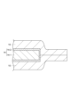
- FIG. 3 is a partial cross-sectional view of the terminal resin film and the metal terminal shown in FIG. 2 taken along the line AA.
- FIG. 2 is a cross-sectional view schematically showing an example of the exterior material shown in FIG. 1
- FIG. 4 is a cross-sectional view schematically showing a terminal resin film according to another embodiment of the present disclosure
- FIG. 2 is a plan view showing a structure for obtaining evaluation samples in Examples and Comparative Examples;
- FIG. 1 is a cross-sectional view schematically showing a terminal resin film of an all-solid-state battery according to an embodiment of the present disclosure.
- a terminal resin film (hereinafter also simply referred to as “terminal resin film”) 10 of the all-solid-state battery of the present embodiment includes a first sealant layer 1, an insulating layer 2 and a second sealant layer 3. are prepared in this order. That is, the terminal resin film 10 is a multilayer film.
- the first sealant layer 1 is provided on the first surface 2 a side of the insulating layer 2
- the second sealant layer 3 is provided on the second surface 2 b side of the insulating layer 2 .
- the first sealant layer 1 and the second sealant layer 3 are provided on both sides of the insulating layer 2 .
- the moisture content of the terminal resin film 10 is 2700 ppm by mass or less.
- the terminal resin film 10 may have an adhesive layer for bonding the first sealant layer 1 and the insulating layer 2 together.
- the terminal resin film 10 may have an adhesive layer for bonding the second sealant layer 3 and the insulating layer 2 together.
- the terminal resin film 10 when the terminal resin film 10 is heat-sealed to the metal terminal, the number of air bubbles in the terminal resin film 10 is reduced compared to when the terminal resin film 10 has a moisture content of more than 2700 ppm by mass. Occurrence can be further suppressed.
- the terminal resin film 10 since the terminal resin film 10 is composed of a multilayer film including the insulating layer 2 and the first sealant layer 1 and the second sealant layer 3 provided on both sides of the insulating layer 2, the terminal resin film 10 functions It is possible to separate them. That is, the thickness of the terminal resin film 10 is ensured by the insulating layer 2, and the insulating property at the time of heat sealing is ensured.
- the first sealant layer 1 can fill the gap between the terminal resin film 10 and the metal terminal.
- the second sealant layer 3 can be heat-sealed (heat-sealed) to the exterior bag of the all-solid-state battery.
- the insulating layer 2 prevents the terminal resin film 10 from Since the thickness is guaranteed, stable insulation is ensured.
- the water content of the terminal resin film 10 may be 2700 mass ppm or less, but may be 2600 mass ppm or less, 2500 mass ppm or less, or 2200 mass ppm or less.
- the water content of the terminal resin film 10 is preferably 2000 mass ppm or less, more preferably 1500 mass ppm or less.
- the moisture content of the terminal resin film 10 may be 0 mass ppm.
- the moisture content of the terminal resin film 10 may be 200 mass ppm or more, 300 mass ppm or more, 400 mass ppm or more, or 500 mass ppm or more.
- each of the first sealant layer 1, the insulating layer 2, and the second sealant layer 3 may have a water content of 2700 mass ppm or less, but some layers have a water content of 2700 mass ppm or less and the remaining Even if the water content in the layer is higher than 2700 ppm by mass, the total water content should be 2700 ppm by mass or less.
- the first sealant layer 1 is a layer that is adhered to a portion of the outer peripheral surface of the metal terminal 14 by heat sealing (thermal fusion bonding).
- first sealant layer 1 examples include thermoplastic resins such as polyolefin resins, polyamide resins, polyester resins, polycarbonate resins, polyphenylene ether resins, polyacetal resins, polystyrene resins, polyvinyl chloride resins, and polyvinyl acetate resins.
- thermoplastic resins such as polyolefin resins, polyamide resins, polyester resins, polycarbonate resins, polyphenylene ether resins, polyacetal resins, polystyrene resins, polyvinyl chloride resins, and polyvinyl acetate resins.
- a film can be used. Sealing suitability and heat resistance can be controlled by blending the various resins listed above to form a polymer alloy.
- a film containing a polyolefin resin hereinafter also referred to as a "polyolefin film”
- a film containing a polyester resin hereinafter also referred to as a “polyester film”
- the sealing performance with respect to the metal terminal and the exterior bag is improved.
- the polyolefin film and the polyester film have heat resistance, the terminal resin film 10 can further improve the heat resistance of the all-solid-state battery.
- Polyolefin resins include, for example, low-density, medium-density or high-density polyethylene; ethylene- ⁇ -olefin copolymers; polypropylene; block or random copolymers containing propylene as a copolymerization component; Examples include polyolefin resins such as polymers.
- the polyolefin resin may be an acid-modified polyolefin resin obtained by modifying a polyolefin resin with acid or glycidyl.
- the first sealant layer 1 is preferably an acid-modified polyolefin resin layer containing an acid-modified polyolefin resin. In this case, since the acid-modified polyolefin resin layer has excellent adhesion to metal, the adhesion between the terminal resin film 10 and the metal terminal can be further improved.
- polyester resins examples include polyethylene terephthalate (PET) resin, polybutylene terephthalate (PBT) resin, polyethylene naphthalate (PEN) resin, polybutylene naphthalate (PBN) resin, and copolymers thereof. be done.
- PET polyethylene terephthalate
- PBT polybutylene terephthalate
- PEN polyethylene naphthalate
- PBN polybutylene naphthalate
- copolymers thereof be done.
- One of these polyester-based resins may be used alone, or two or more thereof may be used in combination. Copolymerization of any acid and glycol may also be used.
- the first sealant layer 1 contains, for example, an antioxidant, a slip agent, a flame retardant, an antiblocking agent, a light stabilizer, a dehydrating agent, a tackifier, and a crystal nucleus in order to impart sealability, heat resistance and other functionality. Additives such as agents and plasticizers may be further included as necessary.
- the melting point of the first sealant layer 1 is not particularly limited, it is preferably 150°C or higher, more preferably 155°C or higher, and even more preferably 160°C or higher. Since the melting point of the first sealant layer 1 is 150° C. or higher, even if the terminal resin film 10 is used in a high-temperature environment, it is possible to suppress a decrease in the sealing strength of the terminal resin film 10 against the metal terminals. .
- the all-solid-state battery contains a sulfide-based solid electrolyte as a solid electrolyte in the exterior bag, gas such as hydrogen sulfide is generated due to the reaction between the moisture and the sulfide-based solid electrolyte in the exterior bag of the all-solid-state battery. Even if it occurs, such gas leakage can be further suppressed.
- the melting point of the first sealant layer 1 is preferably 250°C or lower, more preferably 240°C or lower, and even more preferably 230°C or lower.
- the heat sealing temperature can be lowered by setting the melting point of the first sealant layer 1 to 250° C. or less. Therefore, when the terminal resin film 10 is heat-sealed to the metal terminal, the generation of air bubbles in the first sealant layer 1 can be further suppressed. Therefore, deterioration of the sealing strength and barrier properties of the terminal resin film 10 to the metal terminal is further suppressed. Therefore, the terminal resin film 10 can more sufficiently maintain the sealing performance of the exterior bag of the all-solid-state battery. In addition, the terminal resin film 10 can also suppress penetration of moisture through the terminal resin film 10 .
- the thickness of the first sealant layer 1 is not particularly limited, it is preferably 10-200 ⁇ m, more preferably 20-150 ⁇ m. When the thickness of the first sealant layer 1 is 10 ⁇ m or more, the gap between the metal terminal and the terminal resin film 10 is easily filled with the resin constituting the first sealant layer 1 . In addition, since the thickness of the first sealant layer 1 is 200 ⁇ m or less, the amount of heat required to melt the first sealant layer 1 can be reduced, so that the sealing of the terminal resin film 10 to the metal terminal is facilitated. It can be performed at a low temperature in a short time, shortening the tact time, and further improving productivity.
- the thickness of the first sealant layer 1 may be greater than the thickness of the second sealant layer 3 or less than the thickness of the second sealant layer 3, but is preferably greater than the thickness of the second sealant layer 3. .
- the thickness of the first sealant layer 1 is greater than the thickness of the second sealant layer 3 so that the terminal resin film 10 is heated to the metal terminal at a high temperature. Since the amount of resin filling the gap between the first sealant layer 1 and the metal terminal can be made larger than that of the second sealant layer 3 when sealing, the gap can be filled more easily.
- the first sealant layer 1 and the second sealant layer 3 have the same thickness, and the first sealant layer 1 and the second sealant layer 3 contain the same resin.
- the first sealant layer 1 can be used as the second sealant layer 3 and the second sealant layer 3 can be used as the first sealant layer 1, and the terminal resin film 10 can be fused to the metal terminal.
- the resin contained in the first sealant layer 1 and the second sealant layer 3 is preferably an acid-modified polyolefin resin. In this case, even when the second sealant layer 3 is heat-sealed to the metal terminal, the adhesion between the metal terminal and the terminal resin film is improved.
- the insulating layer 2 is a layer for suppressing thinning (seal thinning) of the terminal resin film 10 during heat sealing and ensuring insulation between the metal terminal and the metal layer of the exterior material.
- a film containing a thermoplastic resin such as polyolefin resin, polyamide resin, polyester resin, polycarbonate resin, polyphenylene ether resin, polyacetal resin, polystyrene resin, polyvinyl chloride resin, polyvinyl acetate resin, etc.
- a thermoplastic resin such as polyolefin resin, polyamide resin, polyester resin, polycarbonate resin, polyphenylene ether resin, polyacetal resin, polystyrene resin, polyvinyl chloride resin, polyvinyl acetate resin, etc.
- Sealing suitability and heat resistance can be controlled by blending the various resins listed above to form a polymer alloy.
- the terminal resin film 10 can further improve the heat resistance of the all-solid-state battery.
- the insulating layer 2 contains, for example, an antioxidant, a slip agent, a flame retardant, an antiblocking agent, a light stabilizer, a dehydrating agent, a tackifier, and a crystal nucleus in order to impart sealability, heat resistance, and other functionality.
- Additives such as agents, colorants, plasticizers, etc. may be further included as necessary.
- the melting point of the insulating layer 2 is not particularly limited, it is preferably 150°C or higher, more preferably 155°C or higher, and even more preferably 160°C or higher.
- the insulating layer 2 has a melting point of 150° C. or higher, it is possible to suppress deterioration in sealing strength of the terminal resin film 10 against metal terminals even when the terminal resin film 10 is used in a high-temperature environment. Therefore, when the all-solid-state battery contains a sulfide-based solid electrolyte as a solid electrolyte in the exterior bag, gas such as hydrogen sulfide is generated due to the reaction between the moisture and the sulfide-based solid electrolyte in the exterior bag of the all-solid-state battery. Even if it occurs, such gas leakage can be further suppressed.
- the melting point of the insulating layer 2 is preferably 250°C or lower, more preferably 240°C or lower, and even more preferably 230°C or lower.
- the melting point of the insulating layer 2 may be higher than the melting points of the resins contained in the first sealant layer 1 and the second sealant layer 3, and not higher than the melting points of the resins contained in the first sealant layer 1 and the second sealant layer 3. However, it is preferably higher than the melting points of the resins contained in the first sealant layer 1 and the second sealant layer.
- the terminal resin film 10 is heat-sealed with an exterior material including a barrier layer made of a metal layer, it is possible to suppress the seal thinning (thinning) of the insulating layer 2 , and the barrier layer of the exterior material and the metal terminal can be suppressed. It becomes easy to secure insulation between.
- the thickness of the insulating layer 2 is not particularly limited, it is preferably 10 to 200 ⁇ m, more preferably 20 to 150 ⁇ m. Sufficient insulation can be obtained by setting the thickness of the insulating layer 2 to 10 ⁇ m or more. By setting the thickness of the insulating layer 2 to 100 ⁇ m or less, it is possible to reduce the amount of water vapor that enters from the peripheral portion of the terminal resin film 10 .
- the second sealant layer 3 is a layer that is heat-sealed (heat-sealed) to the exterior bag of the all-solid-state battery.
- the second sealant layer 3 examples include thermoplastic resins such as polyolefin resins, polyamide resins, polyester resins, polycarbonate resins, polyphenylene ether resins, polyacetal resins, polystyrene resins, polyvinyl chloride resins, and polyvinyl acetate resins.
- thermoplastic resins such as polyolefin resins, polyamide resins, polyester resins, polycarbonate resins, polyphenylene ether resins, polyacetal resins, polystyrene resins, polyvinyl chloride resins, and polyvinyl acetate resins.
- a film can be used. Sealing suitability and heat resistance can be controlled by blending the various resins listed above to form a polymer alloy.
- the terminal resin film 10 can further improve the heat resistance of the all-solid-state battery.
- Polyolefin resins include, for example, low-density, medium-density or high-density polyethylene; ethylene- ⁇ -olefin copolymers; polypropylene; block or random copolymers containing propylene as a copolymerization component; Examples include polyolefin resins such as polymers.
- the polyolefin resin may be an acid-modified polyolefin resin obtained by modifying a polyolefin resin with acid or glycidyl.
- polyester resins examples include polyethylene terephthalate (PET) resin, polybutylene terephthalate (PBT) resin, polyethylene naphthalate (PEN) resin, polybutylene naphthalate (PBN) resin, and copolymers thereof. be done.
- PET polyethylene terephthalate
- PBT polybutylene terephthalate
- PEN polyethylene naphthalate
- PBN polybutylene naphthalate
- copolymers thereof be done.
- One of these polyester-based resins may be used alone, or two or more thereof may be used in combination. Copolymerization of any acid and glycol may also be used.
- the second sealant layer 3 is also composed of a polyolefin film.
- a laminated film composed of the first sealant layer 1, the insulating layer 2 and the second sealant layer 3 can be formed by co-extrusion, and the adhesion strength between the layers can be further increased.
- the first sealant layer 1 and the insulating layer 2 are made of a polyester film
- the second sealant layer 3 is also made of a polyester film. In this case, good adhesion can be obtained when the first sealant layer 1, the insulating layer 2 and the second sealant layer 3 are adhered with a heat-resistant polyester-based adhesive.
- the second sealant layer 3 contains, for example, an antioxidant, a slip agent, a flame retardant, an antiblocking agent, a light stabilizer, a dehydrating agent, a tackifier, a Additives such as crystal nucleating agents and plasticizers may be further included as necessary.
- the melting point of the second sealant layer 3 is not particularly limited, it is preferably 150°C or higher, more preferably 155°C or higher, and even more preferably 160°C or higher. Since the melting point of the second sealant layer 3 is 150° C. or higher, even when the terminal resin film 10 is used in a high-temperature environment, it is possible to suppress a decrease in the sealing strength of the terminal resin film 10 against the metal terminals. .
- the all-solid-state battery contains a sulfide-based solid electrolyte as a solid electrolyte in the exterior bag, gas such as hydrogen sulfide is generated due to the reaction between the moisture and the sulfide-based solid electrolyte in the exterior bag of the all-solid-state battery. Even if it occurs, such gas leakage can be further suppressed.
- the melting point of the second sealant layer 3 is preferably 250°C or lower, more preferably 240°C or lower, and even more preferably 230°C or lower.
- the heat sealing temperature can be lowered by setting the melting point of the second sealant layer 3 to 250° C. or lower. Therefore, when the terminal resin film 10 is heat-sealed to the exterior bag, the generation of air bubbles in the second sealant layer 2 can be further suppressed. Therefore, deterioration of the sealing strength and barrier properties of the terminal resin film 10 to the metal terminal is further suppressed. Therefore, the terminal resin film 10 can more sufficiently maintain the sealing performance of the exterior bag of the all-solid-state battery. In addition, the terminal resin film 10 can also suppress penetration of moisture through the terminal resin film 10 .
- the melting point of the second sealant layer 3 may be the same as or different from the melting point of the first sealant layer 1, but preferably the same.
- the thickness of the second sealant layer 3 is not particularly limited, it is preferably 10-200 ⁇ m, more preferably 20-150 ⁇ m. Sufficient sealing strength can be obtained by setting the thickness of the second sealant layer 3 to 10 ⁇ m or more. Since the thickness of the second sealant layer 3 is 200 ⁇ m or less, the amount of heat required to melt the second sealant layer 3 can be reduced. Sealing can be performed at a low temperature in a short time, shortening the tact time and further improving productivity.
- the terminal resin film 10 is used in an all-solid-state battery having a sulfide-based solid electrolyte
- at least one of the layers constituting the terminal resin film 10 of the present embodiment contains hydrogen sulfide that decomposes or adsorbs hydrogen sulfide. It may contain a decomposition adsorption material.
- the hydrogen sulfide decomposition and adsorption material is contained in, for example, the first sealant layer 1, the insulating layer 2, the second sealant layer 3, or the adhesive layer.
- Hydrogen sulfide decomposition and adsorption materials include zinc oxide, amorphous metal silicates (mainly containing copper and zinc as metals), hydrates of zirconium and tantanoid elements, and tetravalent metal phosphates (especially those containing metals).
- copper amorphous metal silicates (mainly containing copper and zinc as metals), hydrates of zirconium and tantanoid elements, and tetravalent metal phosphates (especially those containing metals).
- copper mixtures of zeolite and zinc ions, mixtures of zeolite, zinc oxide and copper(II) oxide, potassium permanganate, sodium permanganate, silver sulfate, silver acetate, aluminum oxide, iron hydroxide, Isocyanate compounds, aluminum silicate, potassium aluminum sulfate, zeolite, activated carbon, amine compounds, ionomers and the like.
- the hydrogen sulfide decomposition and adsorption material preferably contains zinc oxide (ZnO) and/or zinc ions from the viewpoints of making hydrogen sulfide more harmless and from the viewpoint of cost and handling.
- the hydrogen sulfide decomposition and adsorption material can be used alone or in combination of two or more.
- the hydrogen sulfide decomposition and adsorption material As the hydrogen sulfide decomposition and adsorption material, the following deodorant that has a deodorant effect on hydrogen sulfide may be used. Specifically, for example, Dainichi Seika Kogyo Co., Ltd.'s "Daime Shoe PE-M 3000-Z” (polyethylene masterbatch product), Toagosei Co., Ltd.'s “Kesmon”, Rasa Kogyo Co., Ltd.'s “Shokulens , and "Dashlight ZU” and "Dashlight CZU” manufactured by Sinanen Zeomic Co., Ltd.
- a metallic soap such as zinc stearate may be added to the layer containing the hydrogen sulfide decomposition and adsorption material from the viewpoint of improving the dispersibility of the hydrogen sulfide decomposition and adsorption material.
- the dispersibility of the hydrogen sulfide decomposition and adsorption material in the layer can be improved, and the effect of detoxifying hydrogen sulfide is less likely to occur. It is easy to suppress deterioration of the function (for example, adhesion strength, seal strength, etc.) of the layer containing the adsorbent material.
- the hydrogen sulfide decomposition/adsorption material may be used as a masterbatch in advance.
- a high-concentration blended product is prepared in advance as a masterbatch.
- the masterbatch may be blended with the resin of at least one of the first sealant layer 1, the insulating layer 2, the second sealant layer 3 and the adhesive layer so as to obtain an appropriate concentration.
- the hydrogen sulfide decomposition and adsorption material is preferably blended with the insulating layer 2 .
- the hydrogen sulfide decomposition and adsorption material is not blended in the first sealant layer 1 and the second sealant layer 3, it is possible to further suppress the decrease in the strength between the first sealant layer 1 of the terminal resin film and the metal terminal. , it is possible to further suppress the deterioration of the strength between the second sealant layer 3 of the terminal resin film and the exterior material.
- the hydrogen sulfide decomposition and adsorption material may be blended in the second sealant layer 3 . Even in this case, since the hydrogen sulfide decomposition and adsorption material is not mixed in the first sealant layer 1, it is possible to further suppress a decrease in the strength between the first sealant layer 1 of the terminal resin film and the metal terminal.
- the hydrogen sulfide decomposition and adsorption material when the adhesive layer is coated, it may be blended directly into the coating liquid, or when the adhesive layer is formed by extrusion or the like. may be blended by preparing a masterbatch in the same manner as the first sealant layer 1 .
- thermoplastic resins such as polyolefin resins, polyamide resins, polyester resins, polycarbonate resins, polyphenylene ether resins, polyacetal resins, polystyrene resins, polyvinyl chloride resins, and polyvinyl acetate resins can be used. Resin can be used.
- the content of the hydrogen sulfide decomposition and adsorption material in the layer containing the hydrogen sulfide decomposition and adsorption material may be 0.01% by mass or more and 30% by mass or less based on the total amount of the layer, and may be 0.05% by mass or more and 20% by mass. It may be less than or equal to 0.1% by mass or more and 15% by mass or less.
- the content of the hydrogen sulfide decomposition and adsorption material is at least the above lower limit value, the effect of detoxifying hydrogen sulfide can be sufficiently obtained, and when it is at most the above upper limit value, the layer containing the hydrogen sulfide decomposition and adsorption material is reduced. A decrease in functions (for example, adhesion strength, seal strength, etc.) can be suppressed.
- the terminal resin film 10 can be obtained, for example, by co-extrusion of the first sealant layer 1, the insulating layer 2 and the second sealant layer 3.
- the terminal resin film 10 can also be obtained by preparing the first sealant layer 1, the insulating layer 2, and the second sealant layer 3 in advance, laminating them, and thermally laminating them.
- the temperature during heat lamination may be higher than the melting point of the first sealant layer 1 and the melting point of the second sealant layer 3 .
- the terminal resin film 10 has the first sealant layer 1, the adhesive layer, the insulating layer 2, and the second sealant layer 3, the two-layer film consisting of the insulating layer 2 and the second sealant layer 3 is formed in advance.
- the two-layer film and the first sealant layer 1 may be laminated using an adhesive by a dry lamination method using an adhesive.
- the terminal resin film 10 and the metal terminal 14 are melt-bonded together by a fusion process. At this time, with the first sealant layer 1 of the terminal resin film 10 shown in FIG. The terminal resin film 10 and the metal terminal 14 are heat-sealed (see FIG. 3).
- the first sealant layer 1 In the fusion process, from the viewpoint of obtaining sufficient adhesiveness and sealing between the terminal resin film 10 and the metal terminal 14, it is preferable to heat the first sealant layer 1 to a temperature higher than the melting point of the first sealant layer 1 +20°C.
- the temperature for heating the terminal resin film 10 may be, for example, 155 to 285°C.
- the heat-sealing time can be determined in consideration of the adhesion to the metal terminal 14 and productivity.
- the heat-sealing time can be appropriately set, for example, within the range of 1 to 60 seconds.
- the terminal resin film 10 and the exterior material 13 are melt-bonded (see FIG. 2). Specifically, the terminal resin film 10 and the exterior material are heat-sealed while simultaneously melting the second sealant layer 3 by heating and adhering the second sealant layer 3 to the exterior material by pressure. .
- the heating temperature may be a temperature at which both the second sealant layer 3 of the terminal resin film 10 and the sealant layer of the exterior material 13 are melted.
- the melting point of the sealant layer having the higher melting point among the second sealant layer 3 of the terminal resin film 10 and the sealant layer of the exterior material 13 is +20°C. It is preferable to set the temperature as above.
- the temperature for heating the terminal resin film 10 may be, for example, 155 to 285°C.
- the heat-sealing time can be determined in consideration of adhesion to the exterior material 13 and productivity.
- the heat-sealing time can be appropriately set, for example, within the range of 1 to 60 seconds.
- FIG. 2 is a perspective view showing an embodiment of an all-solid-state battery produced using the terminal resin film described above.
- the all-solid-state battery 50 includes a battery body 11 having a sulfide-based electrolyte as a solid electrolyte, and two metal terminals (current extraction terminals) 14 for extracting current from the battery body 11 to the outside. , terminal resin film 10, and exterior bag 54 for housing battery body 11 in an airtight state.
- the exterior bag 54 is used as a container for housing the battery body 11 .
- the terminal resin film 10 is adhered to a part of the outer peripheral surface of the metal terminal 14 , and the metal terminal 14 is sandwiched by the exterior bag 54 with the terminal resin film 10 interposed therebetween.
- the first sealant layer 1 is adhered to the metal terminal 14 and the second sealant layer 3 is adhered to the exterior bag 54 .
- the terminal resin film 10 is adhered to the metal terminal 14 by heat sealing.
- the generation of air bubbles in the terminal resin film 10 can be suppressed. Therefore, according to the all-solid-state battery 50, it is possible to prevent the terminal resin film 10 from having a rough portion and a dense portion, resulting in a decrease in the sealing strength with respect to the metal terminal at the rough portion.
- the all-solid-state battery 50 is protected from the exterior bag 54 by the terminal resin film 10 .
- the leakage of the hydrogen sulfide from the exterior bag 54 is suppressed.
- the generation of air bubbles, which tend to become passages for moisture is suppressed, so that the intrusion of moisture from the outside of the terminal resin film 10 is suppressed.
- the battery main body 11, the metal terminals 14, and the exterior bag 54 will be described in detail below.
- the battery body 11 has at least one power generation element consisting of a positive electrode, a solid electrolyte and a negative electrode.
- the solid electrolyte is not limited to a sulfide-based solid electrolyte, and may be an oxide-based solid electrolyte or the like.
- ⁇ Metal terminal> As shown in FIGS. 2 and 3, the pair of metal terminals 14 has a metal terminal body 14-1 and a corrosion prevention layer 14-2. Of the pair of metal terminal bodies 14-1, one metal terminal body 14-1 is electrically connected to the positive electrode of the battery body 11, and the other metal terminal body 14-1 is connected to the negative electrode of the battery body 11. is electrically connected to The pair of metal terminal main bodies 14-1 extend in a direction away from the battery main body 11, and are partly exposed from the exterior material 13. As shown in FIG.
- the shape of the pair of metal terminal bodies 14-1 can be, for example, a flat plate shape.
- Metal can be used as the material for the metal terminal body 14-1. This metal can be determined in consideration of the structure of the battery body 11 and the material of each component of the battery body 11 .
- the material of the metal terminal main body 14-1 connected to the positive electrode of the battery main body 11 is preferably aluminum.
- the material of the metal terminal main body 14-1 connected to the positive electrode of the battery main body 11 may be an aluminum material with a purity of 97% or higher, such as 1N30.
- an O material that has been tempered by sufficient annealing may be used for the purpose of adding flexibility.
- the material of the metal terminal main body 14-1 connected to the negative electrode of the battery main body 11 can be composed of, for example, copper with a nickel plating layer formed on its surface, or nickel.
- the thickness of the metal terminal body 14-1 can be determined according to the size and capacity of the all-solid-state battery 50. If the all-solid-state battery 50 is small, the thickness of the metal terminal body 14-1 may be 50 ⁇ m or more. In the case of a large-sized all-solid-state battery for power storage, in-vehicle use, etc., the thickness of the metal terminal main body 14-1 can be appropriately set within the range of 100 to 1000 ⁇ m.
- the corrosion prevention layer 14-2 is arranged so as to cover the surface of the metal terminal body 14-1.
- the corrosion prevention layer 14-2 is a layer for suppressing corrosion of the metal terminal body 14-1 from corrosive components such as hydrogen sulfide.
- the exterior bag 54 is obtained by overlapping two exterior materials 13 and heat-sealing the overlapped peripheral edge portions.
- the exterior bag 54 can also be obtained by folding the exterior material 13 in half and heat-sealing the overlapped peripheral edges.
- the exterior material 13 includes, from the battery body 11 side, a sealant layer 21, a first adhesive layer 22, a corrosion prevention treatment layer 23-1, a barrier layer 24, a corrosion prevention treatment layer 23-2, and a second adhesive layer.
- An agent layer 25 and a substrate layer 26 are provided in this order (see FIG. 4).
- the sealant layer 21 is a layer that imparts sealing properties to the exterior material 13 by heat sealing, and is a layer that is arranged inside and heat-sealed (heat-sealed) when the all-solid-state battery 50 is assembled.
- a polyolefin resin or an acid-modified polyolefin resin obtained by graft-modifying a polyolefin resin with maleic anhydride or the like can be used.
- polystyrene resin low-density, medium-density and high-density polyethylene; ethylene- ⁇ -olefin copolymer; homo, block or random polypropylene; propylene- ⁇ -olefin copolymer and the like can be used.
- the polyolefin resin preferably contains polypropylene.
- the sealant layer 21 may be a single-layer film or a multi-layer film in which multiple layers are laminated, depending on the required functions. Specifically, it may be a multi-layer film in which a resin such as an ethylene-cyclic olefin copolymer or polymethylpentene is interposed in order to impart moisture resistance.
- the sealant layer 21 may contain various additives (flame retardants, slip agents, antiblocking agents, antioxidants, light stabilizers, tackifiers, etc.).
- the thickness of the sealant layer 21 is preferably 10-150 ⁇ m, more preferably 30-80 ⁇ m.
- the thickness of the sealant layer 21 is 10 ⁇ m or more, the exterior material 13 can have sufficient adhesion to the exterior material 13 or the terminal resin film 10 .
- the thickness of the sealant layer 21 is 150 ⁇ m or less, the cost of the exterior material 13 can be suppressed.
- a known adhesive such as a dry lamination adhesive or an acid-modified heat-sealable resin can be appropriately selected and used.
- the corrosion prevention treatment layers 23-1 and 23-2 are preferably formed on both sides of the barrier layer 24 in terms of performance.
- the corrosion prevention treatment layer 23-1 may be arranged only on the surface of the barrier layer 24 that is to be exposed.
- the barrier layer 24 may be a conductive metal layer.
- materials for the barrier layer 24 include aluminum and stainless steel, and aluminum is preferable from the viewpoint of cost, mass (density), and the like.
- a polyurethane-based adhesive containing polyester polyol, polyether polyol, acrylic polyol, or the like as a main ingredient can be used.
- the base material layer 26 may be a single layer film such as nylon or polyethylene terephthalate (PET), or a multilayer film. Like the sealant layer 21, the base material layer 26 may contain various additives (flame retardants, slip agents, antiblocking agents, antioxidants, light stabilizers, tackifiers, etc.).
- the exterior material 13 may further include a protective layer (not shown) for protecting the base material layer 26 on the surface of the base material layer 26 opposite to the sealant layer 21 .
- an adhesive resin layer may be used.
- At least one layer among the layers constituting the exterior material 13 of the present embodiment may contain a hydrogen sulfide decomposition and adsorption material, similar to the terminal resin film 10 .
- a hydrogen sulfide decomposition and adsorption material similar to the terminal resin film 10 .
- the hydrogen sulfide decomposition and adsorption material is contained in, for example, the first adhesive layer 22, the second adhesive layer 25, the sealant layer 21, or at least one layer of these.
- the hydrogen sulfide decomposition and adsorption material is preferably contained in the sealant layer 21 . In this case, permeation of hydrogen sulfide through the exterior material 13 is effectively suppressed.
- the terminal resin film 10 includes the first sealant layer 1, the insulating layer 2, and the second sealant layer 3.
- the terminal resin film 10 is It is not necessary to have the insulating layer 2 .
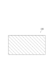
- the terminal resin film may be composed of a single layer film like the terminal resin film 110 shown in FIG. In this case, the terminal resin film 110 has a moisture content of 2700 ppm by mass or less.
- the terminal resin film 110 may be composed of either the first sealant layer 1 , the insulating layer 2 or the second sealant layer 3 .
- Example 1 A film made of acid-modified polypropylene (thickness: 25 ⁇ m, melting point: 140° C.), a film made of polypropylene (thickness: 50 ⁇ m, melting point: 164° C.), and a film made of acid-modified polypropylene (thickness: 25 ⁇ m, melting point: 140° C.) were coextruded to obtain a polyolefin film 1 (PO film 1) having a thickness of 100 ⁇ m. The water content of the obtained PO film 1 was 358 mass ppm.
- Example 2 PO film 1 was changed to polyolefin film 2 (PO film 2) made of polypropylene-polyethylene random copolymer (manufactured by Futamura Chemical Co., Ltd., trade name: FHK2, melting point: 135° C.), and the thickness was changed from 100 ⁇ m to 40 ⁇ m.
- a resin film for a terminal was obtained in the same manner as in Example 1 except for the above. The moisture content of the obtained terminal resin film was 516 mass ppm.
- Example 3 Example except that the PO film 1 was changed to a polyester film (polyester film 1) made of polyethylene terephthalate (manufactured by Unitika Ltd., trade name: Emblet, melting point: 257° C.) and the thickness was changed from 100 ⁇ m to 25 ⁇ m.
- a terminal resin film was obtained in the same manner as in Example 1. The moisture content of the obtained terminal resin film was 2682 mass ppm.
- Example 4 Example except that the PO film 1 was changed to a polyester film (polyester film 2) made of polyethylene naphthalate (manufactured by Toyobo Co., Ltd., trade name: Teonex, melting point: 265° C.) and the thickness was changed from 100 ⁇ m to 25 ⁇ m.
- a terminal resin film was obtained in the same manner as in Example 1. The moisture content of the obtained terminal resin film was 2637 mass ppm.
- Example 5 Example 1 was repeated except that the PO film 1 was changed to a polyester film (polyester film 3) made of a copolymer of multiple types of polyethylene terephthalate (melting point: 210°C) and the thickness was changed from 100 ⁇ m to 25 ⁇ m. A terminal resin film was obtained. The moisture content of the obtained terminal resin film was 1648 mass ppm.
- polyester film 3 made of a copolymer of multiple types of polyethylene terephthalate (melting point: 210°C) and the thickness was changed from 100 ⁇ m to 25 ⁇ m.
- a terminal resin film was obtained.
- the moisture content of the obtained terminal resin film was 1648 mass ppm.
- the PO film 1 was a film made of acid-modified polypropylene (thickness: 25 ⁇ m, melting point: 165° C.), a film made of polypropylene (thickness: 50 ⁇ m, melting point: 165° C.), and a film made of acid-modified polypropylene (thickness: 25 ⁇ m, melting point: 165° C.).
- a terminal resin film was obtained in the same manner as in Example 1, except that the polyolefin film 3 (PO film 3) was changed to a laminate formed by co-extrusion. The moisture content of the obtained terminal resin film was 546 mass ppm.
- Example 1 Example 1 except that the PO film 1 was changed to a polyamide film (PA film) made of nylon 6 (manufactured by Toyobo Co., Ltd., trade name: Harden N1102, melting point: 225° C.), and the thickness was changed from 100 ⁇ m to 25 ⁇ m.
- a terminal resin film was obtained in the same manner as in the above.
- the moisture content of the obtained terminal resin film was 23729 mass ppm.
- the moisture content was measured as follows. That is, a terminal resin film cut into 10 cm squares was left in an environment of 23 ° C. / 50% RH for two days, and then a heating moisture vaporizer set at 300 ° C.
- Moisture content (mass ppm) measured moisture content (g) / mass of terminal resin film (g)
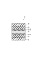
- a terminal resin film was cut into a size of 120 mm ⁇ 60 mm, folded in half, and both ends of the terminal resin film were overlapped in the longitudinal direction.
- the film was heat-sealed for 10 seconds at a temperature of +20° C. to the melting point of the film to form a heat-sealed portion having a width of 10 mm (hatched portion in FIG. 6), thereby producing a structure.
- the structure was then stored at room temperature for 12 hours. After that, a central portion of the heat-sealed portion in the longitudinal direction was cut out from the structure with a width of 15 mm ⁇ 30 mm (see the broken line portion in FIG. 6) to prepare an evaluation sample.
- this evaluation sample was separated into two separate pieces at the fused portion. Then, the fused portion of the separated pieces was visually observed, and the state of occurrence of air bubbles in the terminal resin film was evaluated based on the following criteria. Table 1 shows the results.
- the "melting point of the terminal resin film" is the outermost sealant layer having the lowest melting point among the layers constituting the multi-layer film. melting point. (Evaluation criteria) ⁇ : no bubbles are observed ⁇ : bubbles are observed locally ⁇ : bubbles are observed on the entire surface
- the resin film for terminals of the all-solid-state battery of the present disclosure can suppress the generation of air bubbles when heat-sealed to metal terminals.
- SYMBOLS 1 First sealant layer (sealant layer), 2... Insulating layer, 3... Second sealant layer (sealant layer), 10, 110... Resin film for terminal, 11... Battery body, 14... Metal terminal, 50... All solid battery.
Landscapes
- Chemical & Material Sciences (AREA)
- Chemical Kinetics & Catalysis (AREA)
- Electrochemistry (AREA)
- General Chemical & Material Sciences (AREA)
- Engineering & Computer Science (AREA)
- Manufacturing & Machinery (AREA)
- Physics & Mathematics (AREA)
- Condensed Matter Physics & Semiconductors (AREA)
- General Physics & Mathematics (AREA)
- Inorganic Chemistry (AREA)
- Sealing Battery Cases Or Jackets (AREA)
- Secondary Cells (AREA)
Abstract
In the present invention, a terminal resin film of an all solid state battery is adhered by a heat seal to the outer peripheral surface of a portion of a metal terminal electrically connected to a battery body constituting an all solid state battery, wherein the moisture content is 2700 ppm by mass or less. The terminal resin film may also be formed from a multilayer film having an insulation layer and a sealant layer provided to at least one surface of the insulation layer.
Description
本発明は、全固体電池の端子用樹脂フィルム及び全固体電池に関する。
The present invention relates to a terminal resin film for an all-solid-state battery and an all-solid-state battery.
近年、大容量化が可能な全固体電池の開発が急速に進んでいる。全固体電池は、現在のリチウムイオン電池とは異なり、電解質が固体であることから今までは実現できなかった高温での使用が可能となり、電池を冷却する設備が不要となるため、それに伴うスペース効率の向上、コストダウン、低電力化が期待される。
In recent years, the development of all-solid-state batteries capable of increasing capacity has progressed rapidly. Unlike the current lithium-ion batteries, all-solid-state batteries can be used at high temperatures that were previously unattainable because the electrolyte is solid, and there is no need for equipment to cool the battery, so the space associated with that is reduced. It is expected to improve efficiency, reduce costs, and reduce power consumption.
このような全固体電池は、固体電解質及び電極などの電池本体を収容する外装袋と、電池本体から電流を取り出すためのタブと呼ばれる金属端子とを備えており、金属端子の一部の外周面は、端子用樹脂フィルム(「タブシーラント」と呼ばれることもある)によって覆われている。
Such an all-solid-state battery includes an exterior bag that houses a battery body such as a solid electrolyte and electrodes, and a metal terminal called a tab for extracting current from the battery body. are covered with a terminal resin film (sometimes called a "tab sealant").
このような端子用樹脂フィルムとして、従来、例えば下記特許文献1に記載のものが知られている。同文献には、電流取出し端子に対する密着性を有する樹脂組成物からなり、この樹脂組成物が、融点が160℃以上の熱可塑性樹脂を含み、且つ、融点が160℃未満の熱可塑性樹脂を含まない端子用樹脂フィルムが開示されている。
Conventionally, as such a terminal resin film, for example, the one described in Patent Document 1 below is known. In the document, it is composed of a resin composition having adhesion to a current take-out terminal, and the resin composition contains a thermoplastic resin having a melting point of 160°C or higher and a thermoplastic resin having a melting point of less than 160°C. A terminal resin film is disclosed.
しかし、上述した特許文献1に記載の全固体電池の端子用樹脂フィルムは、以下に示す課題を有していた。
すなわち、上記特許文献1に記載の端子用樹脂フィルムは、金属端子に対してヒートシールさせると、端子用樹脂フィルムに全面的に気泡の発生が見られることがあった。 However, the terminal resin film for the all-solid-state battery described inPatent Document 1 described above has the following problems.
That is, when the resin film for terminals described inPatent Document 1 is heat-sealed to a metal terminal, air bubbles may be generated over the entire surface of the resin film for terminals.
すなわち、上記特許文献1に記載の端子用樹脂フィルムは、金属端子に対してヒートシールさせると、端子用樹脂フィルムに全面的に気泡の発生が見られることがあった。 However, the terminal resin film for the all-solid-state battery described in
That is, when the resin film for terminals described in
本開示は、上記課題に鑑みてなされたものであり、金属端子にヒートシールさせる場合に気泡の発生を抑制できる全固体電池の端子用樹脂フィルム及び全固体電池を提供することを目的とする。
The present disclosure has been made in view of the above problems, and aims to provide a terminal resin film for an all-solid-state battery and an all-solid-state battery that can suppress the generation of air bubbles when heat-sealed to a metal terminal.
本発明者らは、上記のように端子用樹脂フィルムに全面的に気泡の発生が見られる現象が生じる原因について検討した。その結果、端子用樹脂フィルムに全面的に気泡の発生が見られたのは、金属端子に端子用樹脂フィルムを高温でヒートシールさせることが原因ではないかと考えた。すなわち、端子用樹脂フィルムを金属端子に高温でヒートシールさせると、端子用樹脂フィルム中の水分が気化し、生成された気泡が一気に膨張して他の気泡と容易に結合して成長し、冷却後に残るためではないかと本発明者らは考えた。また、上記現象は、端子用樹脂フィルム中の含水率に大きく依存するのではないかと本発明者らは考えた。そこで、本発明者らはさらに鋭意研究を重ねた結果、以下の開示により上記課題を解決し得ることを見出した。
The inventors of the present invention have investigated the cause of the phenomenon in which air bubbles are generated all over the terminal resin film as described above. As a result, it was thought that the reason why bubbles were generated all over the terminal resin film was that the terminal resin film was heat-sealed to the metal terminal at a high temperature. That is, when the terminal resin film is heat-sealed to the metal terminal at a high temperature, the moisture in the terminal resin film evaporates, and the generated air bubbles expand at once and easily combine with other air bubbles to grow and cool. The inventors of the present invention thought that it might be to remain behind. Further, the inventors considered that the above phenomenon largely depends on the water content in the terminal resin film. Therefore, the inventors of the present invention have further conducted extensive research, and as a result, have found that the above-described problems can be solved by the following disclosure.
すなわち、本開示は、全固体電池を構成する電池本体と電気的に接続される金属端子の一部の外周面にヒートシールにより接着される全固体電池の端子用樹脂フィルムであって、含水率が2700質量ppm以下である、全固体電池の端子用樹脂フィルムである。
That is, the present disclosure is a resin film for a terminal of an all-solid-state battery that is adhered by heat sealing to a part of the outer peripheral surface of a metal terminal that is electrically connected to a battery body that constitutes an all-solid-state battery, wherein the water content is is 2700 mass ppm or less, the resin film for a terminal of an all-solid-state battery.
上記端子用樹脂フィルムによれば、当該端子用樹脂フィルムを、金属端子の一部の外周面にヒートシールさせる場合に、当該端子用樹脂フィルムにおける気泡の発生を抑制できる。このため、端子用樹脂フィルムに粗な部分(気泡が多い部分)と密な部分(気泡が少ない部分)とが生じて粗な部分で金属端子に対するシール強度が低下することが抑制される。したがって、高温環境下での全固体電池の使用により固体電解質を含む電池本体が膨張して外装袋に開封しようとする力が働いても、端子用樹脂フィルムは外装袋の密封状態を維持させることができる。このため、全固体電池が固体電解質として硫化物系固体電解質を外装袋内に収容する場合に、全固体電池の外装袋内で水分と硫化物系固体電解質との反応により硫化水素等のガスが発生しても、そのようなガスの漏洩を抑制することができる。また、端子用樹脂フィルムにおいて、水分の通路となりやすい気泡の発生が抑制されるため、外装材の外部から端子用樹脂フィルムへの水分の侵入が抑制される。このため、全固体電池が固体電解質として硫化物系固体電解質を外装袋内に収容する場合には、水分と硫化物系固体電解質との反応による硫化水素の発生を抑制することもできる。
According to the terminal resin film, when the terminal resin film is heat-sealed to a part of the outer peripheral surface of the metal terminal, the generation of air bubbles in the terminal resin film can be suppressed. For this reason, it is possible to prevent the resin film for terminals from having rough portions (portions with many bubbles) and dense portions (portions with few bubbles) and lowering of the sealing strength to the metal terminals at the rough portions. Therefore, even if the battery body including the solid electrolyte expands due to the use of the all-solid-state battery in a high-temperature environment, and a force acts on the exterior bag to open it, the terminal resin film can maintain the sealed state of the exterior bag. can be done. Therefore, when the all-solid-state battery contains a sulfide-based solid electrolyte as a solid electrolyte in the exterior bag, gas such as hydrogen sulfide is generated due to the reaction between the moisture and the sulfide-based solid electrolyte in the exterior bag of the all-solid-state battery. Even if it occurs, such gas leakage can be suppressed. In addition, in the terminal resin film, since the generation of air bubbles, which tend to become passages for moisture, is suppressed, the intrusion of moisture from the outside of the exterior material into the terminal resin film is suppressed. Therefore, when the all-solid-state battery contains a sulfide-based solid electrolyte as a solid electrolyte in the exterior bag, generation of hydrogen sulfide due to a reaction between moisture and the sulfide-based solid electrolyte can be suppressed.
上記端子用樹脂フィルムの含水率は2000質量ppm以下であってもよい。この場合、当該端子用樹脂フィルムを、金属端子の一部の外周面にヒートシールさせる場合に、当該端子用樹脂フィルムにおける気泡の発生をより十分に抑制できる。
上記端子用樹脂フィルムの含水率は200質量ppm以上であってもよい。
上記端子用樹脂フィルムは、絶縁層と、前記絶縁層の少なくとも一面側に設けられるシーラント層とを有する多層フィルムからなることが好ましい。 The moisture content of the terminal resin film may be 2000 ppm by mass or less. In this case, when the terminal resin film is heat-sealed to a part of the outer peripheral surface of the metal terminal, the generation of air bubbles in the terminal resin film can be suppressed more sufficiently.
The moisture content of the terminal resin film may be 200 ppm by mass or more.
It is preferable that the terminal resin film is a multilayer film having an insulating layer and a sealant layer provided on at least one side of the insulating layer.
この場合、端子用樹脂フィルムを機能分離させることが可能となる。すなわち、絶縁層により端子用樹脂フィルムの厚みが担保されてヒートシール時の絶縁性が確保される。一方、シーラント層は、端子用樹脂フィルムと金属端子との隙間を埋めることが可能となる。また、端子用樹脂フィルムを金属端子にヒートシールする時にシーラント層が流動化されてシーラント層の絶縁性にバラツキが生じても、絶縁層によって端子用樹脂フィルムの厚みが担保されるため、安定した絶縁性が確保される。
上記多層フィルムにおいては、前記シーラント層が前記絶縁層の両面側に設けられてもよい。 In this case, it is possible to separate the functions of the terminal resin film. In other words, the insulating layer ensures the thickness of the resin film for terminals and ensures insulation during heat sealing. On the other hand, the sealant layer can fill the gap between the terminal resin film and the metal terminal. In addition, even if the sealant layer is fluidized when the terminal resin film is heat-sealed to the metal terminal, and the insulation properties of the sealant layer vary, the thickness of the terminal resin film is secured by the insulating layer, so stable Insulation is ensured.
In the multilayer film, the sealant layer may be provided on both sides of the insulating layer.
上記端子用樹脂フィルムにおいては、前記多層フィルムのうち前記シーラント層が酸変性ポリオレフィン樹脂層であることが好ましい。
In the terminal resin film, the sealant layer of the multilayer film is preferably an acid-modified polyolefin resin layer.
この場合、酸変性ポリオレフィン樹脂層が金属との密着性に優れるため、端子用樹脂フィルムのシーラント層と金属端子との密着性をより向上させることができる。
In this case, since the acid-modified polyolefin resin layer has excellent adhesion to metal, the adhesion between the sealant layer of the terminal resin film and the metal terminal can be further improved.
上記端子用樹脂フィルムは、ポリオレフィン系樹脂を含むポリオレフィンフィルム又はポリエステル系樹脂を含むポリエステルフィルムであることが好ましい。
The terminal resin film is preferably a polyolefin film containing a polyolefin resin or a polyester film containing a polyester resin.
この場合、全固体電池において、金属端子及び外装袋に対するシール性がより良好となる。また、ポリオレフィンフィルム及びポリエステルフィルムは耐熱性を有するため、端子用樹脂フィルムは、全固体電池の耐熱性をより向上させることができる。
In this case, in the all-solid-state battery, the sealing performance with respect to the metal terminals and the exterior bag is better. Moreover, since the polyolefin film and the polyester film have heat resistance, the terminal resin film can further improve the heat resistance of the all-solid-state battery.
上記端子用樹脂フィルムは、250℃以下の融点を有することが好ましい。
The terminal resin film preferably has a melting point of 250°C or less.
この場合、端子用樹脂フィルムが250℃以下の融点を有することで、ヒートシール温度を低下させることができる。このため、当該端子用樹脂フィルムを金属端子にヒートシールさせる際に、端子用樹脂フィルムにおいて気泡の発生をより抑制することができる。したがって、端子用樹脂フィルムのシール強度及びバリア性の低下がより抑制される。このため、上記端子用樹脂フィルムは、全固体電池の外装袋の密封性をより十分に維持させることができる。また、端子用樹脂フィルムは、当該端子用樹脂フィルムを通じた水分の侵入を抑制することもできる。
In this case, the heat sealing temperature can be lowered by making the terminal resin film have a melting point of 250°C or less. Therefore, when the terminal resin film is heat-sealed to the metal terminal, it is possible to further suppress the generation of air bubbles in the terminal resin film. Therefore, deterioration of the sealing strength and barrier properties of the terminal resin film is further suppressed. Therefore, the resin film for terminals can more sufficiently maintain the sealing performance of the exterior bag of the all-solid-state battery. Moreover, the resin film for terminals can also suppress penetration of moisture through the resin film for terminals.
上記端子用樹脂フィルムは、150℃以上の融点を有することが好ましい。
The terminal resin film preferably has a melting point of 150°C or higher.
この場合、端子用樹脂フィルムが150℃以上の融点を有することで、端子用樹脂フィルムが高温環境下で使用されても、金属端子に対する端子用樹脂フィルムのシール強度が低下することを抑制することができる。このため、全固体電池が固体電解質として硫化物系固体電解質を外装袋内に収容する場合に、全固体電池の外装袋内で水分と硫化物系固体電解質との反応により硫化水素等のガスが発生しても、そのようなガスの漏洩をより抑制することができる。
In this case, the resin film for terminals has a melting point of 150° C. or higher, so that even when the resin film for terminals is used in a high-temperature environment, deterioration in the sealing strength of the resin film for terminals against metal terminals can be suppressed. can be done. Therefore, when the all-solid-state battery contains a sulfide-based solid electrolyte as a solid electrolyte in the exterior bag, gas such as hydrogen sulfide is generated due to the reaction between the moisture and the sulfide-based solid electrolyte in the exterior bag of the all-solid-state battery. Even if it occurs, such gas leakage can be further suppressed.
また、本開示は、固体電解質を含む電池本体と、前記電池本体と電気的に接続された金属端子と、前記金属端子を挟持し且つ前記電池本体を収容する外装袋と、前記金属端子の一部の外周面にヒートシールにより接着される端子用樹脂フィルムとを備え、前記端子用樹脂フィルムが、上述した端子用樹脂フィルムからなる、全固体電池である。
Further, the present disclosure includes a battery body including a solid electrolyte, a metal terminal electrically connected to the battery body, an exterior bag that sandwiches the metal terminal and houses the battery body, and one of the metal terminals. and a terminal resin film adhered to the outer peripheral surface of the portion by heat sealing, wherein the terminal resin film is made of the terminal resin film described above.
この全固体電池によれば、端子用樹脂フィルムが、ヒートシールにより金属端子の一部の外周面に接着される。ここで、上述した端子用樹脂フィルムによれば、当該端子用樹脂フィルムを金属端子にヒートシールさせる場合に、当該端子用樹脂フィルムにおける気泡の発生を抑制できる。このため、本開示の全固体電池によれば、端子用樹脂フィルムに粗な部分と密な部分とが生じて粗な部分で金属端子に対するシール強度が低下することが抑制される。したがって、高温環境下での全固体電池の使用により電池本体が膨張して外装袋に開封しようとする力が働いても、全固体電池は端子用樹脂フィルムにより外装袋の密封状態を維持できる。また、端子用樹脂フィルムにおいて、水分の通路となりやすい気泡の発生が抑制されるため、全固体電池の外部からの水分の侵入が抑制される。
上記全固体電池においては、上記固体電解質が硫化物系固体電解質であってもよい。 According to this all-solid-state battery, the terminal resin film is adhered to a part of the outer peripheral surface of the metal terminal by heat sealing. Here, according to the terminal resin film described above, when the terminal resin film is heat-sealed to the metal terminal, the generation of air bubbles in the terminal resin film can be suppressed. For this reason, according to the all-solid-state battery of the present disclosure, it is possible to prevent the terminal resin film from having rough portions and dense portions, resulting in a decrease in the sealing strength with respect to the metal terminal at the rough portions. Therefore, even if the battery main body expands due to the use of the all-solid-state battery in a high-temperature environment and a force acts on the exterior bag to open it, the all-solid-state battery can maintain the sealed state of the exterior bag with the terminal resin film. In addition, in the terminal resin film, the generation of air bubbles, which tend to become passages for moisture, is suppressed, so that the intrusion of moisture from the outside of the all-solid-state battery is suppressed.
In the all-solid-state battery, the solid electrolyte may be a sulfide-based solid electrolyte.
なお、本開示において、「融点」はJIS K7121-1987に記載の方法に準拠して求められる「融解ピーク温度」を意味し、融解ピークが2個以上独立して現れる場合には最も低い融解ピーク温度が採用される。
In the present disclosure, "melting point" means "melting peak temperature" determined according to the method described in JIS K7121-1987, and when two or more melting peaks appear independently, the lowest melting peak temperature is employed.
また、本開示において、端子用樹脂フィルムが多層フィルムである場合には、融点とは、多層フィルムを構成する層のうち最も低い融点を有する層の融点をいうものとする。
Further, in the present disclosure, when the terminal resin film is a multilayer film, the melting point refers to the melting point of the layer having the lowest melting point among the layers constituting the multilayer film.
本開示によれば、金属端子にヒートシールさせる場合に気泡の発生を抑制できる全固体電池の端子用樹脂フィルム及び全固体電池が提供される。
According to the present disclosure, a terminal resin film for an all-solid-state battery and an all-solid-state battery that can suppress the generation of air bubbles when heat-sealed to a metal terminal are provided.
以下、図面を参照しながら本開示の好適な実施形態について説明する。なお、図面中、同一又は相当部分には同一符号を付し、重複する説明は省略する。また、図面の寸法比率は図示の比率に限られるものではない。
Preferred embodiments of the present disclosure will be described below with reference to the drawings. In the drawings, the same or corresponding parts are denoted by the same reference numerals, and redundant explanations are omitted. Also, the dimensional ratios in the drawings are not limited to the illustrated ratios.
[全固体電池の端子用樹脂フィルム]
図1は、本開示の一実施形態に係る全固体電池の端子用樹脂フィルムを模式的に表す断面図である。図1に示すように、本実施形態の全固体電池の端子用樹脂フィルム(以下、単に「端子用樹脂フィルム」ともいう)10は、第1シーラント層1、絶縁層2及び第2シーラント層3をこの順に備える。すなわち、端子用樹脂フィルム10は多層フィルムである。ここで、第1シーラント層1は絶縁層2の第1面2a側に設けられ、第2シーラント層3は、絶縁層2の第2面2b側に設けられている。すなわち、第1シーラント層1及び第2シーラント層3が、絶縁層2の両面側に設けられている。また、端子用樹脂フィルム10の含水率は2700質量ppm以下である。なお、端子用樹脂フィルム10は、第1シーラント層1と絶縁層2とを接着する接着剤層を有してもよい。また、端子用樹脂フィルム10は、第2シーラント層3と絶縁層2とを接着する接着剤層を有してもよい。 [Resin film for terminal of all-solid-state battery]
FIG. 1 is a cross-sectional view schematically showing a terminal resin film of an all-solid-state battery according to an embodiment of the present disclosure. As shown in FIG. 1, a terminal resin film (hereinafter also simply referred to as “terminal resin film”) 10 of the all-solid-state battery of the present embodiment includes afirst sealant layer 1, an insulating layer 2 and a second sealant layer 3. are prepared in this order. That is, the terminal resin film 10 is a multilayer film. Here, the first sealant layer 1 is provided on the first surface 2 a side of the insulating layer 2 , and the second sealant layer 3 is provided on the second surface 2 b side of the insulating layer 2 . That is, the first sealant layer 1 and the second sealant layer 3 are provided on both sides of the insulating layer 2 . Moreover, the moisture content of the terminal resin film 10 is 2700 ppm by mass or less. The terminal resin film 10 may have an adhesive layer for bonding the first sealant layer 1 and the insulating layer 2 together. Moreover, the terminal resin film 10 may have an adhesive layer for bonding the second sealant layer 3 and the insulating layer 2 together.
図1は、本開示の一実施形態に係る全固体電池の端子用樹脂フィルムを模式的に表す断面図である。図1に示すように、本実施形態の全固体電池の端子用樹脂フィルム(以下、単に「端子用樹脂フィルム」ともいう)10は、第1シーラント層1、絶縁層2及び第2シーラント層3をこの順に備える。すなわち、端子用樹脂フィルム10は多層フィルムである。ここで、第1シーラント層1は絶縁層2の第1面2a側に設けられ、第2シーラント層3は、絶縁層2の第2面2b側に設けられている。すなわち、第1シーラント層1及び第2シーラント層3が、絶縁層2の両面側に設けられている。また、端子用樹脂フィルム10の含水率は2700質量ppm以下である。なお、端子用樹脂フィルム10は、第1シーラント層1と絶縁層2とを接着する接着剤層を有してもよい。また、端子用樹脂フィルム10は、第2シーラント層3と絶縁層2とを接着する接着剤層を有してもよい。 [Resin film for terminal of all-solid-state battery]
FIG. 1 is a cross-sectional view schematically showing a terminal resin film of an all-solid-state battery according to an embodiment of the present disclosure. As shown in FIG. 1, a terminal resin film (hereinafter also simply referred to as “terminal resin film”) 10 of the all-solid-state battery of the present embodiment includes a
端子用樹脂フィルム10は、端子用樹脂フィルム10の含水率が2700質量ppmを超える場合に比べて、当該端子用樹脂フィルム10を金属端子にヒートシールさせる場合に、端子用樹脂フィルム10における気泡の発生をより抑制することができる。また、端子用樹脂フィルム10が、絶縁層2と、絶縁層2の両面側に設けられる第1シーラント層1及び第2シーラント層3とを含む多層フィルムからなるため、端子用樹脂フィルム10を機能分離させることが可能となる。すなわち、絶縁層2により端子用樹脂フィルム10の厚みが担保されてヒートシール時の絶縁性が確保される。一方、第1シーラント層1は、端子用樹脂フィルム10と金属端子との隙間を埋めることが可能となる。他方、第2シーラント層3は、全固体電池の外装袋にヒートシール(熱融着)させることが可能となる。また、端子用樹脂フィルム10を金属端子にヒートシールする時に第1シーラント層1が流動化されて第1シーラント層1の絶縁性にバラツキが生じても、絶縁層2によって端子用樹脂フィルム10の厚みが担保されるため、安定した絶縁性が確保される。
In the terminal resin film 10, when the terminal resin film 10 is heat-sealed to the metal terminal, the number of air bubbles in the terminal resin film 10 is reduced compared to when the terminal resin film 10 has a moisture content of more than 2700 ppm by mass. Occurrence can be further suppressed. In addition, since the terminal resin film 10 is composed of a multilayer film including the insulating layer 2 and the first sealant layer 1 and the second sealant layer 3 provided on both sides of the insulating layer 2, the terminal resin film 10 functions It is possible to separate them. That is, the thickness of the terminal resin film 10 is ensured by the insulating layer 2, and the insulating property at the time of heat sealing is ensured. On the other hand, the first sealant layer 1 can fill the gap between the terminal resin film 10 and the metal terminal. On the other hand, the second sealant layer 3 can be heat-sealed (heat-sealed) to the exterior bag of the all-solid-state battery. In addition, even if the first sealant layer 1 is fluidized when the terminal resin film 10 is heat-sealed to the metal terminal and the insulation properties of the first sealant layer 1 vary, the insulating layer 2 prevents the terminal resin film 10 from Since the thickness is guaranteed, stable insulation is ensured.
端子用樹脂フィルム10の含水率は2700質量ppm以下であればよいが、2600質量ppm以下、2500質量ppm以下又は2200質量ppm以下であってもよい。端子用樹脂フィルム10の含水率は、好ましくは2000質量ppm以下であり、より好ましくは1500質量ppm以下である。端子用樹脂フィルム10の含水率は0質量ppmであってもよい。
また、端子用樹脂フィルム10の含水率は200質量ppm以上、300質量ppm以上、400質量ppm以上又は500質量ppm以上であってもよい。 The water content of theterminal resin film 10 may be 2700 mass ppm or less, but may be 2600 mass ppm or less, 2500 mass ppm or less, or 2200 mass ppm or less. The water content of the terminal resin film 10 is preferably 2000 mass ppm or less, more preferably 1500 mass ppm or less. The moisture content of the terminal resin film 10 may be 0 mass ppm.
Moreover, the moisture content of theterminal resin film 10 may be 200 mass ppm or more, 300 mass ppm or more, 400 mass ppm or more, or 500 mass ppm or more.
また、端子用樹脂フィルム10の含水率は200質量ppm以上、300質量ppm以上、400質量ppm以上又は500質量ppm以上であってもよい。 The water content of the
Moreover, the moisture content of the
なお、端子用樹脂フィルム10においては、全体として含水率が2700質量ppm以下であればよい。したがって、第1シーラント層1、絶縁層2及び第2シーラント層3の各々において、含水率が2700質量ppm以下であってもよいが、一部の層で含水率を2700質量ppm以下とし残りの層で含水率を2700質量ppmより大きくしても、全体として含水率が2700質量ppm以下となればよい。
It should be noted that the terminal resin film 10 may have a moisture content of 2700 ppm by mass or less as a whole. Therefore, each of the first sealant layer 1, the insulating layer 2, and the second sealant layer 3 may have a water content of 2700 mass ppm or less, but some layers have a water content of 2700 mass ppm or less and the remaining Even if the water content in the layer is higher than 2700 ppm by mass, the total water content should be 2700 ppm by mass or less.
以下、端子用樹脂フィルム10を構成する各層について詳細に説明する。
Each layer constituting the terminal resin film 10 will be described in detail below.
<第1シーラント層>
第1シーラント層1は、本実施形態では、金属端子14の一部の外周面にヒートシール(熱融着)により接着される層である。 <First sealant layer>
In this embodiment, thefirst sealant layer 1 is a layer that is adhered to a portion of the outer peripheral surface of the metal terminal 14 by heat sealing (thermal fusion bonding).
第1シーラント層1は、本実施形態では、金属端子14の一部の外周面にヒートシール(熱融着)により接着される層である。 <First sealant layer>
In this embodiment, the
第1シーラント層1としては、例えば、ポリオレフィン系樹脂、ポリアミド樹脂、ポリエステル系樹脂、ポリカーボネート樹脂、ポリフェニレンエーテル樹脂、ポリアセタール樹脂、ポリスチレン樹脂、ポリ塩化ビニル樹脂、ポリ酢酸ビニル樹脂などの熱可塑性樹脂を含むフィルムを用いることができる。上記に挙げた各種樹脂をブレンドしポリマーアロイ化することで、シール適正や耐熱性を制御することができる。
Examples of the first sealant layer 1 include thermoplastic resins such as polyolefin resins, polyamide resins, polyester resins, polycarbonate resins, polyphenylene ether resins, polyacetal resins, polystyrene resins, polyvinyl chloride resins, and polyvinyl acetate resins. A film can be used. Sealing suitability and heat resistance can be controlled by blending the various resins listed above to form a polymer alloy.
中でも、ポリオレフィン系樹脂を含むフィルム(以下、「ポリオレフィンフィルム」ともいう)又はポリエステル系樹脂を含むフィルム(以下、「ポリエステルフィルム」ともいう)を用いることが好ましい。この場合、金属端子及び外装袋に対するシール性がより良好となる。また、ポリオレフィンフィルム及びポリエステルフィルムは耐熱性を有するため、端子用樹脂フィルム10は、全固体電池の耐熱性をより向上させることができる。
Among them, it is preferable to use a film containing a polyolefin resin (hereinafter also referred to as a "polyolefin film") or a film containing a polyester resin (hereinafter also referred to as a "polyester film"). In this case, the sealing performance with respect to the metal terminal and the exterior bag is improved. Moreover, since the polyolefin film and the polyester film have heat resistance, the terminal resin film 10 can further improve the heat resistance of the all-solid-state battery.
ポリオレフィン系樹脂としては、例えば、低密度、中密度又は高密度のポリエチレン;エチレン-αオレフィン共重合体;ポリプロピレン;プロピレンを共重合成分として含むブロック又はランダム共重合体;及び、プロピレン-αオレフィン共重合体等のポリオレフィン樹脂が挙げられる。ポリオレフィン系樹脂は、ポリオレフィン樹脂を酸又はグリシジルで変性してなる酸変性ポリオレフィン樹脂であってもよい。
中でも、第1シーラント層1は、酸変性ポリオレフィン樹脂を含む酸変性ポリオレフィン樹脂層であることが好ましい。この場合、酸変性ポリオレフィン樹脂層が金属との密着性に優れるため、端子用樹脂フィルム10と金属端子との密着性をより向上させることができる。 Polyolefin resins include, for example, low-density, medium-density or high-density polyethylene; ethylene-α-olefin copolymers; polypropylene; block or random copolymers containing propylene as a copolymerization component; Examples include polyolefin resins such as polymers. The polyolefin resin may be an acid-modified polyolefin resin obtained by modifying a polyolefin resin with acid or glycidyl.
Among them, thefirst sealant layer 1 is preferably an acid-modified polyolefin resin layer containing an acid-modified polyolefin resin. In this case, since the acid-modified polyolefin resin layer has excellent adhesion to metal, the adhesion between the terminal resin film 10 and the metal terminal can be further improved.
中でも、第1シーラント層1は、酸変性ポリオレフィン樹脂を含む酸変性ポリオレフィン樹脂層であることが好ましい。この場合、酸変性ポリオレフィン樹脂層が金属との密着性に優れるため、端子用樹脂フィルム10と金属端子との密着性をより向上させることができる。 Polyolefin resins include, for example, low-density, medium-density or high-density polyethylene; ethylene-α-olefin copolymers; polypropylene; block or random copolymers containing propylene as a copolymerization component; Examples include polyolefin resins such as polymers. The polyolefin resin may be an acid-modified polyolefin resin obtained by modifying a polyolefin resin with acid or glycidyl.
Among them, the
ポリエステル系樹脂としては、例えば、ポリエチレンテレフタレート(PET)樹脂、ポリブチレンテレフタレート(PBT)樹脂、ポリエチレンナフタレート(PEN)樹脂、ポリブチレンナフタレート(PBN)樹脂、及び、それらの共重合体等が挙げられる。これらポリエステル系樹脂は、1種を単独で使用してもよく、2種以上を併用してもよい。また、任意の酸とグリコールを共重合させたものを使用してもよい。
Examples of polyester resins include polyethylene terephthalate (PET) resin, polybutylene terephthalate (PBT) resin, polyethylene naphthalate (PEN) resin, polybutylene naphthalate (PBN) resin, and copolymers thereof. be done. One of these polyester-based resins may be used alone, or two or more thereof may be used in combination. Copolymerization of any acid and glycol may also be used.
第1シーラント層1は、シール性、耐熱性およびその他機能性を付与させるために、例えば酸化防止剤、スリップ剤、難燃剤、アンチブロッキング剤、光安定剤、脱水剤、粘着付与剤、結晶核剤、可塑剤等の添加剤を必要に応じてさらに含んでもよい。
The first sealant layer 1 contains, for example, an antioxidant, a slip agent, a flame retardant, an antiblocking agent, a light stabilizer, a dehydrating agent, a tackifier, and a crystal nucleus in order to impart sealability, heat resistance and other functionality. Additives such as agents and plasticizers may be further included as necessary.
第1シーラント層1の融点は、特に制限されるものではないが、好ましくは150℃以上であり、より好ましくは155℃以上であり、より一層好ましくは、160℃以上である。第1シーラント層1の融点が150℃以上であることで、端子用樹脂フィルム10が高温環境下で使用されても、金属端子に対する端子用樹脂フィルム10のシール強度の低下を抑制することができる。このため、全固体電池が固体電解質として硫化物系固体電解質を外装袋内に収容する場合に、全固体電池の外装袋内で水分と硫化物系固体電解質との反応により硫化水素等のガスが発生しても、そのようなガスの漏洩をより抑制することができる。
Although the melting point of the first sealant layer 1 is not particularly limited, it is preferably 150°C or higher, more preferably 155°C or higher, and even more preferably 160°C or higher. Since the melting point of the first sealant layer 1 is 150° C. or higher, even if the terminal resin film 10 is used in a high-temperature environment, it is possible to suppress a decrease in the sealing strength of the terminal resin film 10 against the metal terminals. . Therefore, when the all-solid-state battery contains a sulfide-based solid electrolyte as a solid electrolyte in the exterior bag, gas such as hydrogen sulfide is generated due to the reaction between the moisture and the sulfide-based solid electrolyte in the exterior bag of the all-solid-state battery. Even if it occurs, such gas leakage can be further suppressed.
第1シーラント層1の融点は、好ましくは250℃以下であり、より好ましくは240℃以下であり、より一層好ましくは230℃以下である。この場合、第1シーラント層1の融点が250℃以下であることで、ヒートシール温度を低下させることができる。このため、端子用樹脂フィルム10を金属端子にヒートシールさせる際に、第1シーラント層1において気泡の発生をより抑制することができる。したがって、端子用樹脂フィルム10の金属端子に対するシール強度及びバリア性の低下がより抑制される。このため、端子用樹脂フィルム10は、全固体電池の外装袋の密封性をより十分に維持させることができる。また、端子用樹脂フィルム10は、当該端子用樹脂フィルム10を通じた水分の侵入を抑制することもできる。
The melting point of the first sealant layer 1 is preferably 250°C or lower, more preferably 240°C or lower, and even more preferably 230°C or lower. In this case, the heat sealing temperature can be lowered by setting the melting point of the first sealant layer 1 to 250° C. or less. Therefore, when the terminal resin film 10 is heat-sealed to the metal terminal, the generation of air bubbles in the first sealant layer 1 can be further suppressed. Therefore, deterioration of the sealing strength and barrier properties of the terminal resin film 10 to the metal terminal is further suppressed. Therefore, the terminal resin film 10 can more sufficiently maintain the sealing performance of the exterior bag of the all-solid-state battery. In addition, the terminal resin film 10 can also suppress penetration of moisture through the terminal resin film 10 .
第1シーラント層1の厚さは、特に限定されるものではないが、10~200μmであることが好ましく、20~150μmであることがより好ましい。第1シーラント層1の厚さが10μm以上であることで、金属端子と端子用樹脂フィルム10との隙間が第1シーラント層1を構成する樹脂によって埋め込まれやすくなる。また、第1シーラント層1の厚さが200μm以下であることで、第1シーラント層1を溶かすために必要な熱量を低下させることができるため、金属端子への端子用樹脂フィルム10のシールを低温・短時間で行うことができ、タクトタイムを短縮することができ、生産性をより向上させることができる。
Although the thickness of the first sealant layer 1 is not particularly limited, it is preferably 10-200 μm, more preferably 20-150 μm. When the thickness of the first sealant layer 1 is 10 μm or more, the gap between the metal terminal and the terminal resin film 10 is easily filled with the resin constituting the first sealant layer 1 . In addition, since the thickness of the first sealant layer 1 is 200 μm or less, the amount of heat required to melt the first sealant layer 1 can be reduced, so that the sealing of the terminal resin film 10 to the metal terminal is facilitated. It can be performed at a low temperature in a short time, shortening the tact time, and further improving productivity.
第1シーラント層1の厚さは、第2シーラント層3の厚さより大きくても、第2シーラント層3の厚さ以下であってもよいが、第2シーラント層3の厚さより大きいことが好ましい。端子用樹脂フィルム10の厚さが同一である場合、第1シーラント層1の厚さが、第2シーラント層3の厚さより大きい方が、端子用樹脂フィルム10を高温で金属端子に対してヒートシールさせる場合に第1シーラント層1と金属端子との隙間を埋める樹脂の量を第2シーラント層3よりも多くすることができるため、その隙間をより埋め易くすることができる。
また、第1シーラント層1と第2シーラント層3の厚さは同じであり、第1シーラント層1及び第2シーラント層3が同じ樹脂を含むことが好ましい。この場合、第1シーラント層1を第2シーラント層3として、第2シーラント層3を第1シーラント層1として使用することができるようになり、端子用樹脂フィルム10の金属端子への融着処理に際して、第1シーラント層1と第2シーラント層3とを区別する必要がなくなり、融着処理作業を効率よく行うことができる。ここで、第1シーラント層1及び第2シーラント層3に含まれる樹脂は、酸変性ポリオレフィン樹脂であることが好ましい。この場合、第2シーラント層3が金属端子にヒートシールされる場合でも、金属端子と端子用樹脂フィルムとの密着性がより良好になる。 The thickness of thefirst sealant layer 1 may be greater than the thickness of the second sealant layer 3 or less than the thickness of the second sealant layer 3, but is preferably greater than the thickness of the second sealant layer 3. . When the thickness of the terminal resin film 10 is the same, the thickness of the first sealant layer 1 is greater than the thickness of the second sealant layer 3 so that the terminal resin film 10 is heated to the metal terminal at a high temperature. Since the amount of resin filling the gap between the first sealant layer 1 and the metal terminal can be made larger than that of the second sealant layer 3 when sealing, the gap can be filled more easily.
Moreover, it is preferable that thefirst sealant layer 1 and the second sealant layer 3 have the same thickness, and the first sealant layer 1 and the second sealant layer 3 contain the same resin. In this case, the first sealant layer 1 can be used as the second sealant layer 3 and the second sealant layer 3 can be used as the first sealant layer 1, and the terminal resin film 10 can be fused to the metal terminal. In this case, there is no need to distinguish between the first sealant layer 1 and the second sealant layer 3, and the fusion bonding work can be performed efficiently. Here, the resin contained in the first sealant layer 1 and the second sealant layer 3 is preferably an acid-modified polyolefin resin. In this case, even when the second sealant layer 3 is heat-sealed to the metal terminal, the adhesion between the metal terminal and the terminal resin film is improved.
また、第1シーラント層1と第2シーラント層3の厚さは同じであり、第1シーラント層1及び第2シーラント層3が同じ樹脂を含むことが好ましい。この場合、第1シーラント層1を第2シーラント層3として、第2シーラント層3を第1シーラント層1として使用することができるようになり、端子用樹脂フィルム10の金属端子への融着処理に際して、第1シーラント層1と第2シーラント層3とを区別する必要がなくなり、融着処理作業を効率よく行うことができる。ここで、第1シーラント層1及び第2シーラント層3に含まれる樹脂は、酸変性ポリオレフィン樹脂であることが好ましい。この場合、第2シーラント層3が金属端子にヒートシールされる場合でも、金属端子と端子用樹脂フィルムとの密着性がより良好になる。 The thickness of the
Moreover, it is preferable that the
<絶縁層2>
絶縁層2は、ヒートシール時の端子用樹脂フィルム10の薄層化(シール痩せ)を抑制し、金属端子と外装材の金属層との間の絶縁性を確保するための層である。 <Insulatinglayer 2>
The insulatinglayer 2 is a layer for suppressing thinning (seal thinning) of the terminal resin film 10 during heat sealing and ensuring insulation between the metal terminal and the metal layer of the exterior material.
絶縁層2は、ヒートシール時の端子用樹脂フィルム10の薄層化(シール痩せ)を抑制し、金属端子と外装材の金属層との間の絶縁性を確保するための層である。 <Insulating
The insulating
絶縁層2としては、例えば、ポリオレフィン系樹脂、ポリアミド樹脂、ポリエステル系樹脂、ポリカーボネート樹脂、ポリフェニレンエーテル樹脂、ポリアセタール樹脂、ポリスチレン樹脂、ポリ塩化ビニル樹脂、ポリ酢酸ビニル樹脂などの熱可塑性樹脂を含むフィルムを用いることができる。上記に挙げた各種樹脂をブレンドしポリマーアロイ化することで、シール適正や耐熱性を制御することができる。
As the insulating layer 2, for example, a film containing a thermoplastic resin such as polyolefin resin, polyamide resin, polyester resin, polycarbonate resin, polyphenylene ether resin, polyacetal resin, polystyrene resin, polyvinyl chloride resin, polyvinyl acetate resin, etc. can be used. Sealing suitability and heat resistance can be controlled by blending the various resins listed above to form a polymer alloy.
中でも、ポリオレフィンフィルム又はポリエステルフィルムを用いることが好ましい。この場合、ポリオレフィンフィルム又はポリエステルフィルムが耐熱性を有するため、端子用樹脂フィルム10は、全固体電池の耐熱性をより向上させることができる。
Among them, it is preferable to use a polyolefin film or a polyester film. In this case, since the polyolefin film or the polyester film has heat resistance, the terminal resin film 10 can further improve the heat resistance of the all-solid-state battery.
また、絶縁層2は、シール性、耐熱性およびその他機能性を付与させるために、例えば酸化防止剤、スリップ剤、難燃剤、アンチブロッキング剤、光安定剤、脱水剤、粘着付与剤、結晶核剤、着色剤、可塑剤等の添加剤を必要に応じてさらに含んでもよい。
In addition, the insulating layer 2 contains, for example, an antioxidant, a slip agent, a flame retardant, an antiblocking agent, a light stabilizer, a dehydrating agent, a tackifier, and a crystal nucleus in order to impart sealability, heat resistance, and other functionality. Additives such as agents, colorants, plasticizers, etc. may be further included as necessary.
絶縁層2の融点は、特に制限されるものではないが、好ましくは150℃以上であり、より好ましくは155℃以上であり、より一層好ましくは、160℃以上である。絶縁層2の融点が150℃以上であることで、端子用樹脂フィルム10が高温環境下で使用されても、金属端子に対する端子用樹脂フィルム10のシール強度の低下を抑制することができる。このため、全固体電池が固体電解質として硫化物系固体電解質を外装袋内に収容する場合に、全固体電池の外装袋内で水分と硫化物系固体電解質との反応により硫化水素等のガスが発生しても、そのようなガスの漏洩をより抑制することができる。
Although the melting point of the insulating layer 2 is not particularly limited, it is preferably 150°C or higher, more preferably 155°C or higher, and even more preferably 160°C or higher. When the insulating layer 2 has a melting point of 150° C. or higher, it is possible to suppress deterioration in sealing strength of the terminal resin film 10 against metal terminals even when the terminal resin film 10 is used in a high-temperature environment. Therefore, when the all-solid-state battery contains a sulfide-based solid electrolyte as a solid electrolyte in the exterior bag, gas such as hydrogen sulfide is generated due to the reaction between the moisture and the sulfide-based solid electrolyte in the exterior bag of the all-solid-state battery. Even if it occurs, such gas leakage can be further suppressed.
絶縁層2の融点は、好ましくは250℃以下であり、より好ましくは240℃以下であり、より一層好ましくは230℃以下である。
The melting point of the insulating layer 2 is preferably 250°C or lower, more preferably 240°C or lower, and even more preferably 230°C or lower.
絶縁層2の融点は、第1シーラント層1及び第2シーラント層3に含まれる樹脂の融点より高くてもよく、第1シーラント層1及び第2シーラント層3に含まれる樹脂の融点以下であってもよいが、第1シーラント層1及び第2シーラント層に含まれる樹脂の融点より高いことが好ましい。この場合、端子用樹脂フィルム10を、金属層からなるバリア層を含む外装材をヒートシールさせる際に、絶縁層2のシール痩せ(薄層化)を抑制でき、外装材のバリア層と金属端子との間で絶縁性を確保しやすくなる。
The melting point of the insulating layer 2 may be higher than the melting points of the resins contained in the first sealant layer 1 and the second sealant layer 3, and not higher than the melting points of the resins contained in the first sealant layer 1 and the second sealant layer 3. However, it is preferably higher than the melting points of the resins contained in the first sealant layer 1 and the second sealant layer. In this case, when the terminal resin film 10 is heat-sealed with an exterior material including a barrier layer made of a metal layer, it is possible to suppress the seal thinning (thinning) of the insulating layer 2 , and the barrier layer of the exterior material and the metal terminal can be suppressed. It becomes easy to secure insulation between.
絶縁層2の厚さは、特に限定されるものではないが、10~200μmであることが好ましく、20~150μmであることがより好ましい。絶縁層2の厚さが10μm以上であることにより、十分な絶縁性を得ることができる。絶縁層2の厚さが100μm以下であることにより、端子用樹脂フィルム10の周縁部からの水蒸気の浸入量を低減することができる。
Although the thickness of the insulating layer 2 is not particularly limited, it is preferably 10 to 200 μm, more preferably 20 to 150 μm. Sufficient insulation can be obtained by setting the thickness of the insulating layer 2 to 10 μm or more. By setting the thickness of the insulating layer 2 to 100 μm or less, it is possible to reduce the amount of water vapor that enters from the peripheral portion of the terminal resin film 10 .
<第2シーラント層>
第2シーラント層3は、本実施形態では、全固体電池の外装袋にヒートシール(熱融着)される層である。 <Second sealant layer>
In this embodiment, thesecond sealant layer 3 is a layer that is heat-sealed (heat-sealed) to the exterior bag of the all-solid-state battery.
第2シーラント層3は、本実施形態では、全固体電池の外装袋にヒートシール(熱融着)される層である。 <Second sealant layer>
In this embodiment, the
第2シーラント層3としては、例えば、ポリオレフィン系樹脂、ポリアミド樹脂、ポリエステル系樹脂、ポリカーボネート樹脂、ポリフェニレンエーテル樹脂、ポリアセタール樹脂、ポリスチレン樹脂、ポリ塩化ビニル樹脂、ポリ酢酸ビニル樹脂などの熱可塑性樹脂を含むフィルムを用いることができる。上記に挙げた各種樹脂をブレンドしポリマーアロイ化することで、シール適正や耐熱性を制御することができる。
Examples of the second sealant layer 3 include thermoplastic resins such as polyolefin resins, polyamide resins, polyester resins, polycarbonate resins, polyphenylene ether resins, polyacetal resins, polystyrene resins, polyvinyl chloride resins, and polyvinyl acetate resins. A film can be used. Sealing suitability and heat resistance can be controlled by blending the various resins listed above to form a polymer alloy.
中でも、ポリオレフィンフィルム又はポリエステルフィルムを用いることが好ましい。この場合、金属端子及び外装袋に対するシール性がより良好となる。また、ポリオレフィンフィルム及びポリエステルフィルムは耐熱性を有するため、端子用樹脂フィルム10は、全固体電池の耐熱性をより向上させることができる。
Among them, it is preferable to use a polyolefin film or a polyester film. In this case, the sealing performance with respect to the metal terminal and the exterior bag is improved. Moreover, since the polyolefin film and the polyester film have heat resistance, the terminal resin film 10 can further improve the heat resistance of the all-solid-state battery.
ポリオレフィン系樹脂としては、例えば、低密度、中密度又は高密度のポリエチレン;エチレン-αオレフィン共重合体;ポリプロピレン;プロピレンを共重合成分として含むブロック又はランダム共重合体;及び、プロピレン-αオレフィン共重合体等のポリオレフィン樹脂が挙げられる。ポリオレフィン系樹脂は、ポリオレフィン樹脂を酸又はグリシジルで変性してなる酸変性ポリオレフィン樹脂であってもよい。
Polyolefin resins include, for example, low-density, medium-density or high-density polyethylene; ethylene-α-olefin copolymers; polypropylene; block or random copolymers containing propylene as a copolymerization component; Examples include polyolefin resins such as polymers. The polyolefin resin may be an acid-modified polyolefin resin obtained by modifying a polyolefin resin with acid or glycidyl.
ポリエステル系樹脂としては、例えば、ポリエチレンテレフタレート(PET)樹脂、ポリブチレンテレフタレート(PBT)樹脂、ポリエチレンナフタレート(PEN)樹脂、ポリブチレンナフタレート(PBN)樹脂、及び、それらの共重合体等が挙げられる。これらポリエステル系樹脂は、1種を単独で使用してもよく、2種以上を併用してもよい。また、任意の酸とグリコールを共重合させたものを使用してもよい。
Examples of polyester resins include polyethylene terephthalate (PET) resin, polybutylene terephthalate (PBT) resin, polyethylene naphthalate (PEN) resin, polybutylene naphthalate (PBN) resin, and copolymers thereof. be done. One of these polyester-based resins may be used alone, or two or more thereof may be used in combination. Copolymerization of any acid and glycol may also be used.
第1シーラント層1及び絶縁層2がポリオレフィンフィルムで構成される場合には、第2シーラント層3もポリオレフィンフィルムで構成されることが好ましい。この場合、第1シーラント層1、絶縁層2及び第2シーラント層3からなる積層フィルムを共押し出しで製膜でき、層間の密着強度をより高くすることができる。また、第1シーラント層1及び絶縁層2がポリエステルフィルムで構成される場合には、第2シーラント層3もポリエステルフィルムで構成されることが好ましい。この場合、第1シーラント層1、絶縁層2及び第2シーラント層3を、耐熱性を有するポリエステル系接着剤で接着する場合に良好な密着性が得られる。
When the first sealant layer 1 and the insulating layer 2 are composed of a polyolefin film, it is preferable that the second sealant layer 3 is also composed of a polyolefin film. In this case, a laminated film composed of the first sealant layer 1, the insulating layer 2 and the second sealant layer 3 can be formed by co-extrusion, and the adhesion strength between the layers can be further increased. Moreover, when the first sealant layer 1 and the insulating layer 2 are made of a polyester film, it is preferable that the second sealant layer 3 is also made of a polyester film. In this case, good adhesion can be obtained when the first sealant layer 1, the insulating layer 2 and the second sealant layer 3 are adhered with a heat-resistant polyester-based adhesive.
また、第2シーラント層3は、シール性、耐熱性およびその他機能性を付与させるために、例えば酸化防止剤、スリップ剤、難燃剤、アンチブロッキング剤、光安定剤、脱水剤、粘着付与剤、結晶核剤、可塑剤等の添加剤を必要に応じてさらに含んでもよい。
In addition, the second sealant layer 3 contains, for example, an antioxidant, a slip agent, a flame retardant, an antiblocking agent, a light stabilizer, a dehydrating agent, a tackifier, a Additives such as crystal nucleating agents and plasticizers may be further included as necessary.
第2シーラント層3の融点は、特に制限されるものではないが、好ましくは150℃以上であり、より好ましくは155℃以上であり、より一層好ましくは160℃以上である。第2シーラント層3の融点が150℃以上であることで、端子用樹脂フィルム10が高温環境下で使用されても、金属端子に対する端子用樹脂フィルム10のシール強度の低下を抑制することができる。このため、全固体電池が固体電解質として硫化物系固体電解質を外装袋内に収容する場合に、全固体電池の外装袋内で水分と硫化物系固体電解質との反応により硫化水素等のガスが発生しても、そのようなガスの漏洩をより抑制することができる。
Although the melting point of the second sealant layer 3 is not particularly limited, it is preferably 150°C or higher, more preferably 155°C or higher, and even more preferably 160°C or higher. Since the melting point of the second sealant layer 3 is 150° C. or higher, even when the terminal resin film 10 is used in a high-temperature environment, it is possible to suppress a decrease in the sealing strength of the terminal resin film 10 against the metal terminals. . Therefore, when the all-solid-state battery contains a sulfide-based solid electrolyte as a solid electrolyte in the exterior bag, gas such as hydrogen sulfide is generated due to the reaction between the moisture and the sulfide-based solid electrolyte in the exterior bag of the all-solid-state battery. Even if it occurs, such gas leakage can be further suppressed.
第2シーラント層3の融点は、好ましくは250℃以下であり、より好ましくは240℃以下であり、より一層好ましくは230℃以下である。この場合、第2シーラント層3の融点が250℃以下であることで、ヒートシール温度を低下させることができる。このため、端子用樹脂フィルム10を外装袋にヒートシールさせる際に、第2シーラント層2において気泡の発生をより抑制することができる。したがって、端子用樹脂フィルム10の金属端子に対するシール強度及びバリア性の低下がより抑制される。このため、端子用樹脂フィルム10は、全固体電池の外装袋の密封性をより十分に維持させることができる。また、端子用樹脂フィルム10は、当該端子用樹脂フィルム10を通じた水分の侵入を抑制することもできる。
The melting point of the second sealant layer 3 is preferably 250°C or lower, more preferably 240°C or lower, and even more preferably 230°C or lower. In this case, the heat sealing temperature can be lowered by setting the melting point of the second sealant layer 3 to 250° C. or lower. Therefore, when the terminal resin film 10 is heat-sealed to the exterior bag, the generation of air bubbles in the second sealant layer 2 can be further suppressed. Therefore, deterioration of the sealing strength and barrier properties of the terminal resin film 10 to the metal terminal is further suppressed. Therefore, the terminal resin film 10 can more sufficiently maintain the sealing performance of the exterior bag of the all-solid-state battery. In addition, the terminal resin film 10 can also suppress penetration of moisture through the terminal resin film 10 .
第2シーラント層3の融点は、第1シーラント層1の融点と同一でも異なってもよいが、同一であることが好ましい。
The melting point of the second sealant layer 3 may be the same as or different from the melting point of the first sealant layer 1, but preferably the same.
第2シーラント層3の厚さは、特に限定されるものではないが、10~200μmであることが好ましく、20~150μmであることがより好ましい。第2シーラント層3の厚さが10μm以上であることにより、十分なシール強度を得ることができる。第2シーラント層3の厚さが200μm以下であることにより、第2シーラント層3を溶かすために必要な熱量を低下させることができるため、全固体電池の外装袋への端子用樹脂フィルム10のシールを低温・短時間で行うことができ、タクトタイムを短縮することができ、生産性をより向上させることができる。
Although the thickness of the second sealant layer 3 is not particularly limited, it is preferably 10-200 μm, more preferably 20-150 μm. Sufficient sealing strength can be obtained by setting the thickness of the second sealant layer 3 to 10 μm or more. Since the thickness of the second sealant layer 3 is 200 μm or less, the amount of heat required to melt the second sealant layer 3 can be reduced. Sealing can be performed at a low temperature in a short time, shortening the tact time and further improving productivity.
<硫化水素分解吸着材料>
端子用樹脂フィルム10が硫化物系固体電解質を有する全固体電池に用いられる場合、本実施形態の端子用樹脂フィルム10を構成する層のうちの少なくとも一層は、硫化水素を分解又は吸着する硫化水素分解吸着材料を含有していてもよい。この場合、全固体電池において、水と硫化物系固体電解質とが反応して硫化水素が発生しても、硫化水素が端子用樹脂フィルム10を透過することが抑制される。硫化水素分解吸着材料は、例えば第1シーラント層1、絶縁層2、第2シーラント層3又は接着剤層のいずれかに含まれる。 <Hydrogen sulfide decomposition and adsorption material>
When theterminal resin film 10 is used in an all-solid-state battery having a sulfide-based solid electrolyte, at least one of the layers constituting the terminal resin film 10 of the present embodiment contains hydrogen sulfide that decomposes or adsorbs hydrogen sulfide. It may contain a decomposition adsorption material. In this case, in the all-solid-state battery, even if water and the sulfide-based solid electrolyte react to generate hydrogen sulfide, hydrogen sulfide is suppressed from permeating the terminal resin film 10 . The hydrogen sulfide decomposition and adsorption material is contained in, for example, the first sealant layer 1, the insulating layer 2, the second sealant layer 3, or the adhesive layer.
端子用樹脂フィルム10が硫化物系固体電解質を有する全固体電池に用いられる場合、本実施形態の端子用樹脂フィルム10を構成する層のうちの少なくとも一層は、硫化水素を分解又は吸着する硫化水素分解吸着材料を含有していてもよい。この場合、全固体電池において、水と硫化物系固体電解質とが反応して硫化水素が発生しても、硫化水素が端子用樹脂フィルム10を透過することが抑制される。硫化水素分解吸着材料は、例えば第1シーラント層1、絶縁層2、第2シーラント層3又は接着剤層のいずれかに含まれる。 <Hydrogen sulfide decomposition and adsorption material>
When the
硫化水素分解吸着材料としては、酸化亜鉛、非晶質金属ケイ酸塩(主に金属が銅、亜鉛であるもの)、ジルコニウム・タンタノイド元素の水和物、4価金属リン酸塩(特に金属が銅であるもの)、ゼオライト及び亜鉛イオンの混合物、ゼオライトと酸化亜鉛と酸化銅(II)との混合物、過マンガン酸カリウム、過マンガン酸ナトリウム、硫酸銀、酢酸銀、酸化アルミニウム、水酸化鉄、イソシアネート化合物、ケイ酸アルミニウム、硫酸アルミニウムカリウム、ゼオライト、活性炭、アミン系化合物、アイオノマー等が挙げられる。また、硫化水素分解吸着材料は、硫化水素をより無害化しやすく、コストや取り扱い性の観点から、酸化亜鉛(ZnO)及び/又は亜鉛イオンを含むものであることが好ましい。硫化水素分解吸着材料は一種を単独で又は二種以上を組み合わせて用いることができる。
Hydrogen sulfide decomposition and adsorption materials include zinc oxide, amorphous metal silicates (mainly containing copper and zinc as metals), hydrates of zirconium and tantanoid elements, and tetravalent metal phosphates (especially those containing metals). copper), mixtures of zeolite and zinc ions, mixtures of zeolite, zinc oxide and copper(II) oxide, potassium permanganate, sodium permanganate, silver sulfate, silver acetate, aluminum oxide, iron hydroxide, Isocyanate compounds, aluminum silicate, potassium aluminum sulfate, zeolite, activated carbon, amine compounds, ionomers and the like. In addition, the hydrogen sulfide decomposition and adsorption material preferably contains zinc oxide (ZnO) and/or zinc ions from the viewpoints of making hydrogen sulfide more harmless and from the viewpoint of cost and handling. The hydrogen sulfide decomposition and adsorption material can be used alone or in combination of two or more.
硫化水素分解吸着材料としては、以下のような硫化水素について消臭効果がある消臭剤を用いてもよい。具体的には、例えば、大日精化工業株式会社製の「ダイムシュー PE-M 3000-Z」(ポリエチレンマスターバッチ品)、東亞合成株式会社製の「ケスモン」、ラサ工業株式会社製の「シュークレンズ」、並びに、株式会社シナネンゼオミック製の「ダッシュライト ZU」及び「ダッシュライト CZU」等が挙げられる。
As the hydrogen sulfide decomposition and adsorption material, the following deodorant that has a deodorant effect on hydrogen sulfide may be used. Specifically, for example, Dainichi Seika Kogyo Co., Ltd.'s "Daime Shoe PE-M 3000-Z" (polyethylene masterbatch product), Toagosei Co., Ltd.'s "Kesmon", Rasa Kogyo Co., Ltd.'s "Shokulens , and "Dashlight ZU" and "Dashlight CZU" manufactured by Sinanen Zeomic Co., Ltd.
硫化水素分解吸着材料を含有する層には、硫化水素分解吸着材料の分散性を向上させる観点から、ステアリン酸亜鉛等の金属石鹸を添加してもよい。硫化水素分解吸着材料を金属石鹸と併用することで、層内での硫化水素分解吸着材料の分散性を高めることができ、硫化水素を無毒化する効果の偏りが生じ難くなると共に、硫化水素分解吸着材料を含有する層の機能(例えば、密着強度やシール強度等)の低下を抑制し易い。
A metallic soap such as zinc stearate may be added to the layer containing the hydrogen sulfide decomposition and adsorption material from the viewpoint of improving the dispersibility of the hydrogen sulfide decomposition and adsorption material. By using the hydrogen sulfide decomposition and adsorption material together with the metal soap, the dispersibility of the hydrogen sulfide decomposition and adsorption material in the layer can be improved, and the effect of detoxifying hydrogen sulfide is less likely to occur. It is easy to suppress deterioration of the function (for example, adhesion strength, seal strength, etc.) of the layer containing the adsorbent material.
硫化水素分解吸着材料は、予めマスターバッチ化して用いてもよい。
硫化水素分解吸着材料が、第1シーラント層1、絶縁層2、第2シーラント層3及び接着剤層のうちの少なくとも1層に配合される場合は、マスターバッチとして事前に高濃度配合品を作製して置き、その後適切な濃度になる様に、第1シーラント層1、絶縁層2、第2シーラント層3及び接着剤層のうちの少なくとも1層の樹脂にマスターバッチを配合してもよい。なお、硫化水素分解吸着材料は、絶縁層2に配合されることが好ましい。この場合、硫化水素分解吸着材料が第1シーラント層1及び第2シーラント層3に配合されないため、端子用樹脂フィルムの第1シーラント層1と金属端子との強度が低下することをより抑制できるとともに、端子用樹脂フィルムの第2シーラント層3と外装材との強度が低下することをより抑制できる。硫化水素分解吸着材料は、第2シーラント層3に配合されてもよい。この場合でも、硫化水素分解吸着材料が第1シーラント層1に配合されないため、端子用樹脂フィルムの第1シーラント層1と金属端子との強度が低下することをより抑制できる。
硫化水素分解吸着材料が上記接着剤層に配合される場合で、接着剤層が塗工される場合は塗工液に直接配合してもよいし、接着剤層が押出等で形成される場合は上記第1シーラント層1と同様にマスターバッチを作製して配合してもよい。なお、マスターバッチを作製する場合、樹脂としては、ポリオレフィン系樹脂、ポリアミド樹脂、ポリエステル系樹脂、ポリカーボネート樹脂、ポリフェニレンエーテル樹脂、ポリアセタール樹脂、ポリスチレン樹脂、ポリ塩化ビニル樹脂、ポリ酢酸ビニル樹脂などの熱可塑性樹脂を用いることができる。 The hydrogen sulfide decomposition/adsorption material may be used as a masterbatch in advance.
When the hydrogen sulfide decomposition and adsorption material is blended in at least one of thefirst sealant layer 1, the insulating layer 2, the second sealant layer 3, and the adhesive layer, a high-concentration blended product is prepared in advance as a masterbatch. After that, the masterbatch may be blended with the resin of at least one of the first sealant layer 1, the insulating layer 2, the second sealant layer 3 and the adhesive layer so as to obtain an appropriate concentration. Note that the hydrogen sulfide decomposition and adsorption material is preferably blended with the insulating layer 2 . In this case, since the hydrogen sulfide decomposition and adsorption material is not blended in the first sealant layer 1 and the second sealant layer 3, it is possible to further suppress the decrease in the strength between the first sealant layer 1 of the terminal resin film and the metal terminal. , it is possible to further suppress the deterioration of the strength between the second sealant layer 3 of the terminal resin film and the exterior material. The hydrogen sulfide decomposition and adsorption material may be blended in the second sealant layer 3 . Even in this case, since the hydrogen sulfide decomposition and adsorption material is not mixed in the first sealant layer 1, it is possible to further suppress a decrease in the strength between the first sealant layer 1 of the terminal resin film and the metal terminal.
When the hydrogen sulfide decomposition and adsorption material is blended in the adhesive layer, when the adhesive layer is coated, it may be blended directly into the coating liquid, or when the adhesive layer is formed by extrusion or the like. may be blended by preparing a masterbatch in the same manner as thefirst sealant layer 1 . When preparing a masterbatch, thermoplastic resins such as polyolefin resins, polyamide resins, polyester resins, polycarbonate resins, polyphenylene ether resins, polyacetal resins, polystyrene resins, polyvinyl chloride resins, and polyvinyl acetate resins can be used. Resin can be used.
硫化水素分解吸着材料が、第1シーラント層1、絶縁層2、第2シーラント層3及び接着剤層のうちの少なくとも1層に配合される場合は、マスターバッチとして事前に高濃度配合品を作製して置き、その後適切な濃度になる様に、第1シーラント層1、絶縁層2、第2シーラント層3及び接着剤層のうちの少なくとも1層の樹脂にマスターバッチを配合してもよい。なお、硫化水素分解吸着材料は、絶縁層2に配合されることが好ましい。この場合、硫化水素分解吸着材料が第1シーラント層1及び第2シーラント層3に配合されないため、端子用樹脂フィルムの第1シーラント層1と金属端子との強度が低下することをより抑制できるとともに、端子用樹脂フィルムの第2シーラント層3と外装材との強度が低下することをより抑制できる。硫化水素分解吸着材料は、第2シーラント層3に配合されてもよい。この場合でも、硫化水素分解吸着材料が第1シーラント層1に配合されないため、端子用樹脂フィルムの第1シーラント層1と金属端子との強度が低下することをより抑制できる。
硫化水素分解吸着材料が上記接着剤層に配合される場合で、接着剤層が塗工される場合は塗工液に直接配合してもよいし、接着剤層が押出等で形成される場合は上記第1シーラント層1と同様にマスターバッチを作製して配合してもよい。なお、マスターバッチを作製する場合、樹脂としては、ポリオレフィン系樹脂、ポリアミド樹脂、ポリエステル系樹脂、ポリカーボネート樹脂、ポリフェニレンエーテル樹脂、ポリアセタール樹脂、ポリスチレン樹脂、ポリ塩化ビニル樹脂、ポリ酢酸ビニル樹脂などの熱可塑性樹脂を用いることができる。 The hydrogen sulfide decomposition/adsorption material may be used as a masterbatch in advance.
When the hydrogen sulfide decomposition and adsorption material is blended in at least one of the
When the hydrogen sulfide decomposition and adsorption material is blended in the adhesive layer, when the adhesive layer is coated, it may be blended directly into the coating liquid, or when the adhesive layer is formed by extrusion or the like. may be blended by preparing a masterbatch in the same manner as the
硫化水素分解吸着材料を含有する層における硫化水素分解吸着材料の含有量は、当該層全量を基準として0.01質量%以上30質量%以下であってよく、0.05質量%以上20質量%以下であってよく、0.1質量%以上15質量%以下であってよい。硫化水素分解吸着材料の含有量が上記下限値以上であることで、硫化水素無害化の効果が十分に得られ易く、上記上限値以下であることで、硫化水素分解吸着材料を含有する層の機能(例えば、密着強度やシール強度等)の低下を抑制できる。
The content of the hydrogen sulfide decomposition and adsorption material in the layer containing the hydrogen sulfide decomposition and adsorption material may be 0.01% by mass or more and 30% by mass or less based on the total amount of the layer, and may be 0.05% by mass or more and 20% by mass. It may be less than or equal to 0.1% by mass or more and 15% by mass or less. When the content of the hydrogen sulfide decomposition and adsorption material is at least the above lower limit value, the effect of detoxifying hydrogen sulfide can be sufficiently obtained, and when it is at most the above upper limit value, the layer containing the hydrogen sulfide decomposition and adsorption material is reduced. A decrease in functions (for example, adhesion strength, seal strength, etc.) can be suppressed.
[端子用樹脂フィルムの製造方法]
次に、端子用樹脂フィルム10の製造方法について説明する。但し、端子用樹脂フィルム10の製造方法は、下記の製造方法に限定されない。 [Method for producing terminal resin film]
Next, a method for manufacturing theterminal resin film 10 will be described. However, the manufacturing method of the terminal resin film 10 is not limited to the following manufacturing method.
次に、端子用樹脂フィルム10の製造方法について説明する。但し、端子用樹脂フィルム10の製造方法は、下記の製造方法に限定されない。 [Method for producing terminal resin film]
Next, a method for manufacturing the
端子用樹脂フィルム10は、例えば第1シーラント層1、絶縁層2及び第2シーラント層3を共押出しすることにより得ることができる。
The terminal resin film 10 can be obtained, for example, by co-extrusion of the first sealant layer 1, the insulating layer 2 and the second sealant layer 3.
端子用樹脂フィルム10は、第1シーラント層1、絶縁層2、第2シーラント層3を予め用意しておき、これらを積層して熱ラミネートさせることにより得ることもできる。
熱ラミネート時の温度は、第1シーラント層1の融点及び第2シーラント層3の融点よりも高い温度であればよい。 Theterminal resin film 10 can also be obtained by preparing the first sealant layer 1, the insulating layer 2, and the second sealant layer 3 in advance, laminating them, and thermally laminating them.
The temperature during heat lamination may be higher than the melting point of thefirst sealant layer 1 and the melting point of the second sealant layer 3 .
熱ラミネート時の温度は、第1シーラント層1の融点及び第2シーラント層3の融点よりも高い温度であればよい。 The
The temperature during heat lamination may be higher than the melting point of the
端子用樹脂フィルム10が第1シーラント層1、接着剤層、絶縁層2、第2シーラント層3を有する場合、絶縁層2及び第2シーラント層3からなる2層フィルムを事前に製膜した後、接着剤を用いて2層フィルムと第1シーラント層1とを、接着剤を用いたドライラミネート法により積層してもよい。
When the terminal resin film 10 has the first sealant layer 1, the adhesive layer, the insulating layer 2, and the second sealant layer 3, the two-layer film consisting of the insulating layer 2 and the second sealant layer 3 is formed in advance. Alternatively, the two-layer film and the first sealant layer 1 may be laminated using an adhesive by a dry lamination method using an adhesive.
[端子用樹脂フィルムの融着方法]
図1に示した端子用樹脂フィルム10と外装袋とを溶融接着する融着処理について説明する。 [Method of fusion-bonding resin film for terminals]
A fusion process for fusion-bonding theterminal resin film 10 and the exterior bag shown in FIG. 1 will be described.
図1に示した端子用樹脂フィルム10と外装袋とを溶融接着する融着処理について説明する。 [Method of fusion-bonding resin film for terminals]
A fusion process for fusion-bonding the
まず、端子用樹脂フィルム10と金属端子14とを溶融接着する融着処理を行う。このとき、図1に示した端子用樹脂フィルム10の第1シーラント層1を金属端子14側に向け、加熱による第1シーラント層1の溶融と、加圧による第1シーラント層1と金属端子14との密着とを同時に行いながら、端子用樹脂フィルム10と金属端子14とを熱融着させる(図3参照)。
First, the terminal resin film 10 and the metal terminal 14 are melt-bonded together by a fusion process. At this time, with the first sealant layer 1 of the terminal resin film 10 shown in FIG. The terminal resin film 10 and the metal terminal 14 are heat-sealed (see FIG. 3).
融着処理では、端子用樹脂フィルム10と金属端子14との充分な密着性及び封止性を得る観点から、第1シーラント層1の融点+20℃以上の温度に加熱することが好ましい。
In the fusion process, from the viewpoint of obtaining sufficient adhesiveness and sealing between the terminal resin film 10 and the metal terminal 14, it is preferable to heat the first sealant layer 1 to a temperature higher than the melting point of the first sealant layer 1 +20°C.
端子用樹脂フィルム10の加熱温度は、例えば、155~285℃であってよい。また、熱融着の時間は、金属端子14との密着性、及び生産性を考慮して決定することができる。熱融着の時間は、例えば、1~60秒の範囲内で適宜設定することができる。
The temperature for heating the terminal resin film 10 may be, for example, 155 to 285°C. Also, the heat-sealing time can be determined in consideration of the adhesion to the metal terminal 14 and productivity. The heat-sealing time can be appropriately set, for example, within the range of 1 to 60 seconds.
次に、端子用樹脂フィルム10と外装材13とを溶融接着する融着処理を行う(図2参照)。具体的には、加熱による第2シーラント層3の溶融と、加圧による第2シーラント層3と外装材との密着とを同時に行いながら、端子用樹脂フィルム10と外装材とを熱融着させる。
Next, the terminal resin film 10 and the exterior material 13 are melt-bonded (see FIG. 2). Specifically, the terminal resin film 10 and the exterior material are heat-sealed while simultaneously melting the second sealant layer 3 by heating and adhering the second sealant layer 3 to the exterior material by pressure. .
融着処理では、端子用樹脂フィルム10の第2シーラント層3及び外装材13のシーラント層を加熱して溶融させる。このとき、加熱温度は、端子用樹脂フィルム10の第2シーラント層3及び外装材13のシーラント層の両方が溶融する温度であればよいが、端子用樹脂フィルム10の第2シーラント層3及び外装材13のシーラント層の充分な密着性及び封止性を得る観点から、端子用樹脂フィルム10の第2シーラント層3及び外装材13のシーラント層のうち融点が高い方のシーラント層の融点+20℃以上の温度とすることが好ましい。
In the fusion bonding process, the second sealant layer 3 of the terminal resin film 10 and the sealant layer of the exterior material 13 are heated and melted. At this time, the heating temperature may be a temperature at which both the second sealant layer 3 of the terminal resin film 10 and the sealant layer of the exterior material 13 are melted. From the viewpoint of obtaining sufficient adhesion and sealing properties of the sealant layer of the material 13, the melting point of the sealant layer having the higher melting point among the second sealant layer 3 of the terminal resin film 10 and the sealant layer of the exterior material 13 is +20°C. It is preferable to set the temperature as above.
端子用樹脂フィルム10の加熱温度は、例えば、155~285℃であってよい。熱融着の時間は、外装材13との密着性、及び生産性を考慮して決定することができる。熱融着の時間は、例えば、1~60秒の範囲内で適宜設定することができる。
The temperature for heating the terminal resin film 10 may be, for example, 155 to 285°C. The heat-sealing time can be determined in consideration of adhesion to the exterior material 13 and productivity. The heat-sealing time can be appropriately set, for example, within the range of 1 to 60 seconds.
[全固体電池]
図2は、上述した端子用樹脂フィルムを用いて作製した全固体電池の一実施形態を示す斜視図である。図2に示されるように、全固体電池50は、固体電解質としての硫化物系電解質を有する電池本体11と、電池本体11から電流を外部に取り出すための2つの金属端子(電流取出し端子)14と、端子用樹脂フィルム10と、電池本体11を気密状態で収容する外装袋54とを含む。外装袋54は電池本体11を収容する容器として用いられる。端子用樹脂フィルム10は、金属端子14の一部の外周面に接着されており、金属端子14は、端子用樹脂フィルム10を介して外装袋54によって挟持されている。端子用樹脂フィルム10では、第1シーラント層1が金属端子14に接着され、第2シーラント層3が外装袋54に接着されている。 [All-solid battery]
FIG. 2 is a perspective view showing an embodiment of an all-solid-state battery produced using the terminal resin film described above. As shown in FIG. 2, the all-solid-state battery 50 includes a battery body 11 having a sulfide-based electrolyte as a solid electrolyte, and two metal terminals (current extraction terminals) 14 for extracting current from the battery body 11 to the outside. , terminal resin film 10, and exterior bag 54 for housing battery body 11 in an airtight state. The exterior bag 54 is used as a container for housing the battery body 11 . The terminal resin film 10 is adhered to a part of the outer peripheral surface of the metal terminal 14 , and the metal terminal 14 is sandwiched by the exterior bag 54 with the terminal resin film 10 interposed therebetween. In the terminal resin film 10 , the first sealant layer 1 is adhered to the metal terminal 14 and the second sealant layer 3 is adhered to the exterior bag 54 .
図2は、上述した端子用樹脂フィルムを用いて作製した全固体電池の一実施形態を示す斜視図である。図2に示されるように、全固体電池50は、固体電解質としての硫化物系電解質を有する電池本体11と、電池本体11から電流を外部に取り出すための2つの金属端子(電流取出し端子)14と、端子用樹脂フィルム10と、電池本体11を気密状態で収容する外装袋54とを含む。外装袋54は電池本体11を収容する容器として用いられる。端子用樹脂フィルム10は、金属端子14の一部の外周面に接着されており、金属端子14は、端子用樹脂フィルム10を介して外装袋54によって挟持されている。端子用樹脂フィルム10では、第1シーラント層1が金属端子14に接着され、第2シーラント層3が外装袋54に接着されている。 [All-solid battery]
FIG. 2 is a perspective view showing an embodiment of an all-solid-state battery produced using the terminal resin film described above. As shown in FIG. 2, the all-solid-
全固体電池50によれば、端子用樹脂フィルム10がヒートシールにより金属端子14と接着される。ここで、端子用樹脂フィルム10によれば、当該端子用樹脂フィルム10を金属端子14にヒートシールさせる場合に、端子用樹脂フィルム10における気泡の発生を抑制できる。このため、全固体電池50によれば、端子用樹脂フィルム10に粗な部分と密な部分とが生じて粗な部分で金属端子に対するシール強度が低下することが抑制される。したがって、高温環境下での全固体電池50の使用により電池本体11が膨張して外装袋54に開封しようとする力が働いても、全固体電池50は、端子用樹脂フィルム10により外装袋54の密封状態を維持できる。その結果、外装袋54内で硫化水素が発生しても、その硫化水素が外装袋54から漏洩することが抑制される。また、第1シーラント層1において、水分の通路となりやすい気泡の発生が抑制されるため、端子用樹脂フィルム10の外部からの水分の侵入が抑制される。その結果、水分と硫化物系電解質との反応により硫化水素が発生することを抑制することができる。
According to the all-solid-state battery 50, the terminal resin film 10 is adhered to the metal terminal 14 by heat sealing. Here, according to the terminal resin film 10, when the terminal resin film 10 is heat-sealed to the metal terminal 14, the generation of air bubbles in the terminal resin film 10 can be suppressed. Therefore, according to the all-solid-state battery 50, it is possible to prevent the terminal resin film 10 from having a rough portion and a dense portion, resulting in a decrease in the sealing strength with respect to the metal terminal at the rough portion. Therefore, even if the battery main body 11 expands due to the use of the all-solid-state battery 50 in a high-temperature environment, and a force that attempts to open the exterior bag 54 acts, the all-solid-state battery 50 is protected from the exterior bag 54 by the terminal resin film 10 . can maintain hermetic condition. As a result, even if hydrogen sulfide is generated in the exterior bag 54, the leakage of the hydrogen sulfide from the exterior bag 54 is suppressed. In addition, in the first sealant layer 1, the generation of air bubbles, which tend to become passages for moisture, is suppressed, so that the intrusion of moisture from the outside of the terminal resin film 10 is suppressed. As a result, it is possible to suppress the generation of hydrogen sulfide due to the reaction between moisture and the sulfide-based electrolyte.
以下、電池本体11、金属端子14及び外装袋54について詳細に説明する。
The battery main body 11, the metal terminals 14, and the exterior bag 54 will be described in detail below.
<電池本体>
電池本体11は、正極、固体電解質及び負極からなる発電素子を少なくとも1つ有する。固体電解質は、硫化物系固体電解質に限られず、酸化物系固体電解質などであってもよい。
<金属端子>
図2及び図3に示すように、一対の金属端子14は、金属端子本体14-1と、腐食防止層14-2とを有する。一対の金属端子本体14-1のうち、一方の金属端子本体14-1は、電池本体11の正極と電気的に接続されており、他方の金属端子本体14-1は、電池本体11の負極と電気的に接続されている。一対の金属端子本体14-1は、電池本体11から離間する方向に延在しており、その一部が外装材13から露出されている。一対の金属端子本体14-1の形状は、例えば、平板形状とすることができる。 <Battery body>
Thebattery body 11 has at least one power generation element consisting of a positive electrode, a solid electrolyte and a negative electrode. The solid electrolyte is not limited to a sulfide-based solid electrolyte, and may be an oxide-based solid electrolyte or the like.
<Metal terminal>
As shown in FIGS. 2 and 3, the pair ofmetal terminals 14 has a metal terminal body 14-1 and a corrosion prevention layer 14-2. Of the pair of metal terminal bodies 14-1, one metal terminal body 14-1 is electrically connected to the positive electrode of the battery body 11, and the other metal terminal body 14-1 is connected to the negative electrode of the battery body 11. is electrically connected to The pair of metal terminal main bodies 14-1 extend in a direction away from the battery main body 11, and are partly exposed from the exterior material 13. As shown in FIG. The shape of the pair of metal terminal bodies 14-1 can be, for example, a flat plate shape.
電池本体11は、正極、固体電解質及び負極からなる発電素子を少なくとも1つ有する。固体電解質は、硫化物系固体電解質に限られず、酸化物系固体電解質などであってもよい。
<金属端子>
図2及び図3に示すように、一対の金属端子14は、金属端子本体14-1と、腐食防止層14-2とを有する。一対の金属端子本体14-1のうち、一方の金属端子本体14-1は、電池本体11の正極と電気的に接続されており、他方の金属端子本体14-1は、電池本体11の負極と電気的に接続されている。一対の金属端子本体14-1は、電池本体11から離間する方向に延在しており、その一部が外装材13から露出されている。一対の金属端子本体14-1の形状は、例えば、平板形状とすることができる。 <Battery body>
The
<Metal terminal>
As shown in FIGS. 2 and 3, the pair of
金属端子本体14-1の材料としては、金属を用いることができる。この金属は、電池本体11の構造や電池本体11の各構成要素の材料等を考慮して決めることができる。
Metal can be used as the material for the metal terminal body 14-1. This metal can be determined in consideration of the structure of the battery body 11 and the material of each component of the battery body 11 .
全固体電池50がリチウムイオン二次電池である場合、正極用集電体としてアルミニウムを用いることができ、負極用集電体として銅を用いることができる。全固体電池50がリチウムイオン二次電池である場合、電池本体11の正極と接続される金属端子本体14-1の材料は、アルミニウムであることが好ましい。また、電池本体11の正極と接続される金属端子本体14-1の材料は、1N30等の純度97%以上のアルミニウム素材であってもよい。さらに、金属端子本体14-1を屈曲させる場合には、柔軟性を付加する目的で十分な焼鈍により調質したO材を用いてもよい。電池本体11の負極と接続される金属端子本体14-1の材料は、例えば表面にニッケルめっき層が形成された銅、又はニッケルで構成することができる。
When the all-solid-state battery 50 is a lithium-ion secondary battery, aluminum can be used as the positive electrode current collector, and copper can be used as the negative electrode current collector. When the all-solid-state battery 50 is a lithium-ion secondary battery, the material of the metal terminal main body 14-1 connected to the positive electrode of the battery main body 11 is preferably aluminum. The material of the metal terminal main body 14-1 connected to the positive electrode of the battery main body 11 may be an aluminum material with a purity of 97% or higher, such as 1N30. Furthermore, when bending the metal terminal main body 14-1, an O material that has been tempered by sufficient annealing may be used for the purpose of adding flexibility. The material of the metal terminal main body 14-1 connected to the negative electrode of the battery main body 11 can be composed of, for example, copper with a nickel plating layer formed on its surface, or nickel.
金属端子本体14-1の厚さは、全固体電池50のサイズや容量に応じて決めることができる。全固体電池50が小型である場合、金属端子本体14-1の厚さは、50μm以上であってよい。蓄電、車載用途等の大型の全固体電池の場合、金属端子本体14-1の厚さは、100~1000μmの範囲内で適宜設定することができる。
The thickness of the metal terminal body 14-1 can be determined according to the size and capacity of the all-solid-state battery 50. If the all-solid-state battery 50 is small, the thickness of the metal terminal body 14-1 may be 50 μm or more. In the case of a large-sized all-solid-state battery for power storage, in-vehicle use, etc., the thickness of the metal terminal main body 14-1 can be appropriately set within the range of 100 to 1000 μm.
腐食防止層14-2は、金属端子本体14-1の表面を覆うように配置されている。全固体電池50において、腐食防止層14-2は、硫化水素等の腐食成分から金属端子本体14-1が腐食されることを抑制するための層である。
The corrosion prevention layer 14-2 is arranged so as to cover the surface of the metal terminal body 14-1. In the all-solid-state battery 50, the corrosion prevention layer 14-2 is a layer for suppressing corrosion of the metal terminal body 14-1 from corrosive components such as hydrogen sulfide.
<外装袋>
図2に示すように、外装袋54は、2枚の外装材13を重ね合わせ、重なり合った周縁部同士をヒートシールすることで得られる。外装袋54は、外装材13を半分に折り曲げて重なり合った周縁部同士をヒートシールすることによっても得られる。外装材13は、電池本体11側から、シーラント層21と、第1接着剤層22と、腐食防止処理層23-1と、バリア層24と、腐食防止処理層23-2と、第2接着剤層25と、基材層26と、をこの順に備える(図4参照)。 <Outer bag>
As shown in FIG. 2, theexterior bag 54 is obtained by overlapping two exterior materials 13 and heat-sealing the overlapped peripheral edge portions. The exterior bag 54 can also be obtained by folding the exterior material 13 in half and heat-sealing the overlapped peripheral edges. The exterior material 13 includes, from the battery body 11 side, a sealant layer 21, a first adhesive layer 22, a corrosion prevention treatment layer 23-1, a barrier layer 24, a corrosion prevention treatment layer 23-2, and a second adhesive layer. An agent layer 25 and a substrate layer 26 are provided in this order (see FIG. 4).
図2に示すように、外装袋54は、2枚の外装材13を重ね合わせ、重なり合った周縁部同士をヒートシールすることで得られる。外装袋54は、外装材13を半分に折り曲げて重なり合った周縁部同士をヒートシールすることによっても得られる。外装材13は、電池本体11側から、シーラント層21と、第1接着剤層22と、腐食防止処理層23-1と、バリア層24と、腐食防止処理層23-2と、第2接着剤層25と、基材層26と、をこの順に備える(図4参照)。 <Outer bag>
As shown in FIG. 2, the
シーラント層21は、外装材13に対し、ヒートシールによる封止性を付与する層であり、全固体電池50の組み立て時に内側に配置されてヒートシール(熱融着)される層である。シーラント層21の母材としては、例えば、ポリオレフィン樹脂、ポリオレフィン樹脂に無水マレイン酸等をグラフト変性させた酸変性ポリオレフィン樹脂を用いることができる。上記ポリオレフィン樹脂としては、低密度、中密度、高密度のポリエチレン;エチレン-αオレフィン共重合体;ホモ、ブロック、又はランダムポリプロピレン;プロピレン-αオレフィン共重合体等を用いることができる。これらの中でも上記ポリオレフィン樹脂は、ポリプロピレンを含むことが好ましい。これらポリオレフィン樹脂は、1種を単独で又は2種以上を組み合わせて用いることができる。
The sealant layer 21 is a layer that imparts sealing properties to the exterior material 13 by heat sealing, and is a layer that is arranged inside and heat-sealed (heat-sealed) when the all-solid-state battery 50 is assembled. As the base material of the sealant layer 21, for example, a polyolefin resin or an acid-modified polyolefin resin obtained by graft-modifying a polyolefin resin with maleic anhydride or the like can be used. As the polyolefin resin, low-density, medium-density and high-density polyethylene; ethylene-α-olefin copolymer; homo, block or random polypropylene; propylene-α-olefin copolymer and the like can be used. Among these, the polyolefin resin preferably contains polypropylene. These polyolefin resins can be used singly or in combination of two or more.
シーラント層21は、必要とされる機能に応じて、単層フィルム、又は複数の層を積層させた多層フィルムであってよい。具体的には、防湿性を付与するために、エチレン-環状オレフィン共重合体、ポリメチルペンテン等の樹脂を介在させた多層フィルムであってよい。シーラント層21は、各種添加剤(難燃剤、スリップ剤、アンチブロッキング剤、酸化防止剤、光安定剤、粘着付与剤等)を含んでよい。
The sealant layer 21 may be a single-layer film or a multi-layer film in which multiple layers are laminated, depending on the required functions. Specifically, it may be a multi-layer film in which a resin such as an ethylene-cyclic olefin copolymer or polymethylpentene is interposed in order to impart moisture resistance. The sealant layer 21 may contain various additives (flame retardants, slip agents, antiblocking agents, antioxidants, light stabilizers, tackifiers, etc.).
シーラント層21の厚さは、10~150μmであることが好ましく、30~80μmであることがより好ましい。シーラント層21の厚さが10μm以上であることで、外装材13は、外装材13、又は、端子用樹脂フィルム10との間で、充分な密着性を有することが可能となる。また、シーラント層21の厚さが150μm以下であることで、外装材13のコストを抑えることができる。
The thickness of the sealant layer 21 is preferably 10-150 μm, more preferably 30-80 μm. When the thickness of the sealant layer 21 is 10 μm or more, the exterior material 13 can have sufficient adhesion to the exterior material 13 or the terminal resin film 10 . Moreover, since the thickness of the sealant layer 21 is 150 μm or less, the cost of the exterior material 13 can be suppressed.
第1接着剤層22としては、ドライラミネーション用接着剤、酸変性された熱融着性樹脂等の公知の接着剤を適宜選択して用いることができる。
As the first adhesive layer 22, a known adhesive such as a dry lamination adhesive or an acid-modified heat-sealable resin can be appropriately selected and used.
図4に示すように、腐食防止処理層23-1、23-2は、バリア層24の両面に形成することが性能上好ましいが、コストを抑える観点から、第1接着剤層22側に位置するバリア層24の面のみに腐食防止処理層23-1を配置してよい。
As shown in FIG. 4, the corrosion prevention treatment layers 23-1 and 23-2 are preferably formed on both sides of the barrier layer 24 in terms of performance. The corrosion prevention treatment layer 23-1 may be arranged only on the surface of the barrier layer 24 that is to be exposed.
バリア層24は、導電性を有する金属層であってよい。バリア層24の材料としては、アルミニウム及びステンレス鋼等が挙げられ、コスト、質量(密度)等の観点から、アルミニウムが好ましい。
The barrier layer 24 may be a conductive metal layer. Examples of materials for the barrier layer 24 include aluminum and stainless steel, and aluminum is preferable from the viewpoint of cost, mass (density), and the like.
第2接着剤層25としては、ポリエステルポリオール、ポリエーテルポリオール、アクリルポリオール等を主剤としたポリウレタン系の接着剤を用いることができる。
As the second adhesive layer 25, a polyurethane-based adhesive containing polyester polyol, polyether polyol, acrylic polyol, or the like as a main ingredient can be used.
基材層26としては、ナイロン、ポリエチレンテレフタレート(PET)等の単層膜、及び多層膜であってよい。基材層26は、シーラント層21と同様に、各種添加剤(難燃剤、スリップ剤、アンチブロッキング剤、酸化防止剤、光安定剤、粘着付与剤等)を含んでよい。
The base material layer 26 may be a single layer film such as nylon or polyethylene terephthalate (PET), or a multilayer film. Like the sealant layer 21, the base material layer 26 may contain various additives (flame retardants, slip agents, antiblocking agents, antioxidants, light stabilizers, tackifiers, etc.).
また、外装材13は、基材層26のシーラント層21とは反対側の面上に、基材層26を保護する保護層(図示せず)を更に備えていてもよい。
In addition, the exterior material 13 may further include a protective layer (not shown) for protecting the base material layer 26 on the surface of the base material layer 26 opposite to the sealant layer 21 .
また、外装材13においては、第1接着剤層22に代えて、接着性樹脂層を用いてもよい。
Also, in the exterior material 13, instead of the first adhesive layer 22, an adhesive resin layer may be used.
本実施形態の外装材13を構成する層のうちの少なくとも一層は、端子用樹脂フィルム10と同様、硫化水素分解吸着材料を含有していてもよい。この場合、全固体電池50において、水と硫化物系固体電解質とが反応して硫化水素が発生しても、硫化水素が外装材13を透過することが抑制される。硫化水素分解吸着材料は、例えば第1接着剤層22、第2接着剤層25、シーラント層21又はこれらのうち少なくとも一層に含有される。特に、硫化水素分解吸着材料は、シーラント層21に含まれることが好ましい。この場合、硫化水素が外装材13を透過することが効果的に抑制される。
At least one layer among the layers constituting the exterior material 13 of the present embodiment may contain a hydrogen sulfide decomposition and adsorption material, similar to the terminal resin film 10 . In this case, even if water and the sulfide-based solid electrolyte react with each other to generate hydrogen sulfide in the all-solid-state battery 50 , hydrogen sulfide is suppressed from permeating the exterior material 13 . The hydrogen sulfide decomposition and adsorption material is contained in, for example, the first adhesive layer 22, the second adhesive layer 25, the sealant layer 21, or at least one layer of these. In particular, the hydrogen sulfide decomposition and adsorption material is preferably contained in the sealant layer 21 . In this case, permeation of hydrogen sulfide through the exterior material 13 is effectively suppressed.
以上、本開示の好ましい実施形態について詳述したが、本開示は上記の実施形態に限定されるものではない。
例えば、端子用樹脂フィルム10は、第1シーラント層1、絶縁層2及び第2シーラント層3を備えているが、外装袋54が金属層を有さない場合には、端子用樹脂フィルム10は絶縁層2を有していなくてもよい。また、端子用樹脂フィルムは、図5に示す端子用樹脂フィルム110のように、単層フィルムで構成されていてもよい。この場合、この端子用樹脂フィルム110は、2700質量ppm以下の含水率を有する。端子用樹脂フィルム110は、第1シーラント層1、絶縁層2又は第2シーラント層3のいずれかで構成されてもよい。 Although preferred embodiments of the present disclosure have been described in detail above, the present disclosure is not limited to the above embodiments.
For example, theterminal resin film 10 includes the first sealant layer 1, the insulating layer 2, and the second sealant layer 3. However, when the exterior bag 54 does not have a metal layer, the terminal resin film 10 is It is not necessary to have the insulating layer 2 . Also, the terminal resin film may be composed of a single layer film like the terminal resin film 110 shown in FIG. In this case, the terminal resin film 110 has a moisture content of 2700 ppm by mass or less. The terminal resin film 110 may be composed of either the first sealant layer 1 , the insulating layer 2 or the second sealant layer 3 .
例えば、端子用樹脂フィルム10は、第1シーラント層1、絶縁層2及び第2シーラント層3を備えているが、外装袋54が金属層を有さない場合には、端子用樹脂フィルム10は絶縁層2を有していなくてもよい。また、端子用樹脂フィルムは、図5に示す端子用樹脂フィルム110のように、単層フィルムで構成されていてもよい。この場合、この端子用樹脂フィルム110は、2700質量ppm以下の含水率を有する。端子用樹脂フィルム110は、第1シーラント層1、絶縁層2又は第2シーラント層3のいずれかで構成されてもよい。 Although preferred embodiments of the present disclosure have been described in detail above, the present disclosure is not limited to the above embodiments.
For example, the
以下、実施例に基づいて本開示をより具体的に説明するが、本開示は以下の実施例に限定されるものではない。
Hereinafter, the present disclosure will be described more specifically based on examples, but the present disclosure is not limited to the following examples.
(実施例1)
酸変性ポリプロピレンからなるフィルム(厚み:25μm、融点:140℃)と、ポリプロピレンからなるフィルム(厚み:50μm、融点:164℃)と、酸変性ポリプロピレンからなるフィルム(厚み:25μm、融点:140℃)を共押出しして、厚さ100μmのポリオレフィンフィルム1(POフィルム1)を得た。得られたPOフィルム1の含水率は358質量ppmであった。 (Example 1)
A film made of acid-modified polypropylene (thickness: 25 μm, melting point: 140° C.), a film made of polypropylene (thickness: 50 μm, melting point: 164° C.), and a film made of acid-modified polypropylene (thickness: 25 μm, melting point: 140° C.) were coextruded to obtain a polyolefin film 1 (PO film 1) having a thickness of 100 μm. The water content of the obtainedPO film 1 was 358 mass ppm.
酸変性ポリプロピレンからなるフィルム(厚み:25μm、融点:140℃)と、ポリプロピレンからなるフィルム(厚み:50μm、融点:164℃)と、酸変性ポリプロピレンからなるフィルム(厚み:25μm、融点:140℃)を共押出しして、厚さ100μmのポリオレフィンフィルム1(POフィルム1)を得た。得られたPOフィルム1の含水率は358質量ppmであった。 (Example 1)
A film made of acid-modified polypropylene (thickness: 25 μm, melting point: 140° C.), a film made of polypropylene (thickness: 50 μm, melting point: 164° C.), and a film made of acid-modified polypropylene (thickness: 25 μm, melting point: 140° C.) were coextruded to obtain a polyolefin film 1 (PO film 1) having a thickness of 100 μm. The water content of the obtained
(実施例2)
POフィルム1を、ポリプロピレン-ポリエチレンランダム共重合体(フタムラ化学株式会社製、商品名:FHK2、融点:135℃)からなるポリオレフィンフィルム2(POフィルム2)に変更し、厚みを100μmから40μmに変更したこと以外は実施例1と同様にして端子用樹脂フィルムを得た。得られた端子用樹脂フィルムの含水率は516質量ppmであった。 (Example 2)
PO film 1 was changed to polyolefin film 2 (PO film 2) made of polypropylene-polyethylene random copolymer (manufactured by Futamura Chemical Co., Ltd., trade name: FHK2, melting point: 135° C.), and the thickness was changed from 100 μm to 40 μm. A resin film for a terminal was obtained in the same manner as in Example 1 except for the above. The moisture content of the obtained terminal resin film was 516 mass ppm.
POフィルム1を、ポリプロピレン-ポリエチレンランダム共重合体(フタムラ化学株式会社製、商品名:FHK2、融点:135℃)からなるポリオレフィンフィルム2(POフィルム2)に変更し、厚みを100μmから40μmに変更したこと以外は実施例1と同様にして端子用樹脂フィルムを得た。得られた端子用樹脂フィルムの含水率は516質量ppmであった。 (Example 2)
(実施例3)
POフィルム1を、ポリエチレンテレフタレート(ユニチカ株式会社製、商品名:エンブレット、融点:257℃)からなるポリエステルフィルム(ポリエステルフィルム1)に変更し、厚みを100μmから25μmに変更したこと以外は実施例1と同様にして端子用樹脂フィルムを得た。得られた端子用樹脂フィルムの含水率は2682質量ppmであった。 (Example 3)
Example except that thePO film 1 was changed to a polyester film (polyester film 1) made of polyethylene terephthalate (manufactured by Unitika Ltd., trade name: Emblet, melting point: 257° C.) and the thickness was changed from 100 μm to 25 μm. A terminal resin film was obtained in the same manner as in Example 1. The moisture content of the obtained terminal resin film was 2682 mass ppm.
POフィルム1を、ポリエチレンテレフタレート(ユニチカ株式会社製、商品名:エンブレット、融点:257℃)からなるポリエステルフィルム(ポリエステルフィルム1)に変更し、厚みを100μmから25μmに変更したこと以外は実施例1と同様にして端子用樹脂フィルムを得た。得られた端子用樹脂フィルムの含水率は2682質量ppmであった。 (Example 3)
Example except that the
(実施例4)
POフィルム1を、ポリエチレンナフタレート(東洋紡株式会社製、商品名:テオネックス、融点:265℃)からなるポリエステルフィルム(ポリエステルフィルム2)に変更し、厚みを100μmから25μmに変更したこと以外は実施例1と同様にして端子用樹脂フィルムを得た。得られた端子用樹脂フィルムの含水率は2637質量ppmであった。 (Example 4)
Example except that thePO film 1 was changed to a polyester film (polyester film 2) made of polyethylene naphthalate (manufactured by Toyobo Co., Ltd., trade name: Teonex, melting point: 265° C.) and the thickness was changed from 100 μm to 25 μm. A terminal resin film was obtained in the same manner as in Example 1. The moisture content of the obtained terminal resin film was 2637 mass ppm.
POフィルム1を、ポリエチレンナフタレート(東洋紡株式会社製、商品名:テオネックス、融点:265℃)からなるポリエステルフィルム(ポリエステルフィルム2)に変更し、厚みを100μmから25μmに変更したこと以外は実施例1と同様にして端子用樹脂フィルムを得た。得られた端子用樹脂フィルムの含水率は2637質量ppmであった。 (Example 4)
Example except that the
(実施例5)
POフィルム1を、複数種類のポリエチレンテレフタレートの共重合体(融点:210℃)からなるポリエステルフィルム(ポリエステルフィルム3)に変更し、厚みを100μmから25μmに変更したこと以外は実施例1と同様にして端子用樹脂フィルムを得た。得られた端子用樹脂フィルムの含水率は1648質量ppmであった。 (Example 5)
Example 1 was repeated except that thePO film 1 was changed to a polyester film (polyester film 3) made of a copolymer of multiple types of polyethylene terephthalate (melting point: 210°C) and the thickness was changed from 100 µm to 25 µm. A terminal resin film was obtained. The moisture content of the obtained terminal resin film was 1648 mass ppm.
POフィルム1を、複数種類のポリエチレンテレフタレートの共重合体(融点:210℃)からなるポリエステルフィルム(ポリエステルフィルム3)に変更し、厚みを100μmから25μmに変更したこと以外は実施例1と同様にして端子用樹脂フィルムを得た。得られた端子用樹脂フィルムの含水率は1648質量ppmであった。 (Example 5)
Example 1 was repeated except that the
(実施例6)
POフィルム1を、酸変性ポリプロピレンからなるフィルム(厚み:25μm、融点:165℃)、ポリプロピレンからなるフィルム(厚み:50μm、融点:165℃)及び酸変性ポリプロピレンからなるフィルム(厚み:25μm、融点:165℃)を共押出ししてなる積層体からなるポリオレフィンフィルム3(POフィルム3)に変更したこと以外は実施例1と同様にして端子用樹脂フィルムを得た。得られた端子用樹脂フィルムの含水率は546質量ppmであった。 (Example 6)
ThePO film 1 was a film made of acid-modified polypropylene (thickness: 25 μm, melting point: 165° C.), a film made of polypropylene (thickness: 50 μm, melting point: 165° C.), and a film made of acid-modified polypropylene (thickness: 25 μm, melting point: 165° C.). A terminal resin film was obtained in the same manner as in Example 1, except that the polyolefin film 3 (PO film 3) was changed to a laminate formed by co-extrusion. The moisture content of the obtained terminal resin film was 546 mass ppm.
POフィルム1を、酸変性ポリプロピレンからなるフィルム(厚み:25μm、融点:165℃)、ポリプロピレンからなるフィルム(厚み:50μm、融点:165℃)及び酸変性ポリプロピレンからなるフィルム(厚み:25μm、融点:165℃)を共押出ししてなる積層体からなるポリオレフィンフィルム3(POフィルム3)に変更したこと以外は実施例1と同様にして端子用樹脂フィルムを得た。得られた端子用樹脂フィルムの含水率は546質量ppmであった。 (Example 6)
The
(比較例1)
POフィルム1を、ナイロン6(東洋紡株式会社製、商品名:ハーデンN1102、融点:225℃)からなるポリアミドフィルム(PAフィルム)に変更し、厚みを100μmから25μmに変更したこと以外は実施例1と同様にして端子用樹脂フィルムを得た。得られた端子用樹脂フィルムの含水率は23729質量ppmであった。
なお、含水率は、以下のようにして測定した。
すなわち、10cm角にカットした端子用樹脂フィルムを23℃/50%RHの環境下で二日間放置した後、300℃に設定した加熱水分気化装置(株式会社HIRANUMA製、商品名:EV-2000)を用いて加熱し、発生した水分の量を、微量水分測定装置(カールフィッシャー:株式会社HIRANUMA製「AQ-2100」)にて測定した。このとき、キャリアガスとして、乾燥したN2ガスを用いた。そして、上記のようにして測定した水分量の値を用い、下記式に基づいて含水率を算出した。
含水率(質量ppm)=測定した水分量(g)/端子用樹脂フィルムの質量(g) (Comparative example 1)
Example 1 except that thePO film 1 was changed to a polyamide film (PA film) made of nylon 6 (manufactured by Toyobo Co., Ltd., trade name: Harden N1102, melting point: 225° C.), and the thickness was changed from 100 μm to 25 μm. A terminal resin film was obtained in the same manner as in the above. The moisture content of the obtained terminal resin film was 23729 mass ppm.
In addition, the moisture content was measured as follows.
That is, a terminal resin film cut into 10 cm squares was left in an environment of 23 ° C. / 50% RH for two days, and then a heating moisture vaporizer set at 300 ° C. (manufactured by HIRANUMA Co., Ltd., product name: EV-2000). and the amount of generated moisture was measured with a trace moisture measuring device (Karl Fischer: "AQ-2100" manufactured by HIRANUMA Co., Ltd.). At this time, dry N2 gas was used as a carrier gas. Then, using the value of the water content measured as described above, the water content was calculated based on the following formula.
Moisture content (mass ppm) = measured moisture content (g) / mass of terminal resin film (g)
POフィルム1を、ナイロン6(東洋紡株式会社製、商品名:ハーデンN1102、融点:225℃)からなるポリアミドフィルム(PAフィルム)に変更し、厚みを100μmから25μmに変更したこと以外は実施例1と同様にして端子用樹脂フィルムを得た。得られた端子用樹脂フィルムの含水率は23729質量ppmであった。
なお、含水率は、以下のようにして測定した。
すなわち、10cm角にカットした端子用樹脂フィルムを23℃/50%RHの環境下で二日間放置した後、300℃に設定した加熱水分気化装置(株式会社HIRANUMA製、商品名:EV-2000)を用いて加熱し、発生した水分の量を、微量水分測定装置(カールフィッシャー:株式会社HIRANUMA製「AQ-2100」)にて測定した。このとき、キャリアガスとして、乾燥したN2ガスを用いた。そして、上記のようにして測定した水分量の値を用い、下記式に基づいて含水率を算出した。
含水率(質量ppm)=測定した水分量(g)/端子用樹脂フィルムの質量(g) (Comparative example 1)
Example 1 except that the
In addition, the moisture content was measured as follows.
That is, a terminal resin film cut into 10 cm squares was left in an environment of 23 ° C. / 50% RH for two days, and then a heating moisture vaporizer set at 300 ° C. (manufactured by HIRANUMA Co., Ltd., product name: EV-2000). and the amount of generated moisture was measured with a trace moisture measuring device (Karl Fischer: "AQ-2100" manufactured by HIRANUMA Co., Ltd.). At this time, dry N2 gas was used as a carrier gas. Then, using the value of the water content measured as described above, the water content was calculated based on the following formula.
Moisture content (mass ppm) = measured moisture content (g) / mass of terminal resin film (g)
<端子用樹脂フィルムの評価>
端子用樹脂フィルムを120mm×60mmのサイズに切り出し、半分に折りたたみ、端子用樹脂フィルムの長手方向の両端部を重ね合わせ、これらの両端部を、0.6MPaの圧力で加圧しながら、端子用樹脂フィルムの融点+20℃の温度で10秒間にわたってヒートシールし、幅が10mmのヒートシール部(図6の斜線部)を形成し、構造体を作製した。その後、構造体を12時間室温で保管した。その後、構造体からヒートシール部の長手方向における中央部を幅15mm×30mmで切り出し(図6の破線部を参照)、評価用サンプルを作製した。そして、この評価用サンプルを、融着部で2つの分離片に分離させた。そして、分離した分離片のうち融着部を目視にて観察し、以下の基準に基づいて端子用樹脂フィルムの気泡の発生状態の評価を行った。結果を表1に示す。なお、「端子用樹脂フィルムの融点」は、端子用樹脂フィルムが多層フィルムである場合には、多層フィルムを構成する層のうち最も融点の低い層であって最も外側に配置されるシーラント層の融点とした。
(評価基準)
◎:気泡の発生が見られない
〇:局所的に気泡の発生が見られる
×:全面的に気泡の発生が見られる <Evaluation of terminal resin film>
A terminal resin film was cut into a size of 120 mm × 60 mm, folded in half, and both ends of the terminal resin film were overlapped in the longitudinal direction. The film was heat-sealed for 10 seconds at a temperature of +20° C. to the melting point of the film to form a heat-sealed portion having a width of 10 mm (hatched portion in FIG. 6), thereby producing a structure. The structure was then stored at room temperature for 12 hours. After that, a central portion of the heat-sealed portion in the longitudinal direction was cut out from the structure with a width of 15 mm×30 mm (see the broken line portion in FIG. 6) to prepare an evaluation sample. Then, this evaluation sample was separated into two separate pieces at the fused portion. Then, the fused portion of the separated pieces was visually observed, and the state of occurrence of air bubbles in the terminal resin film was evaluated based on the following criteria. Table 1 shows the results. When the terminal resin film is a multi-layer film, the "melting point of the terminal resin film" is the outermost sealant layer having the lowest melting point among the layers constituting the multi-layer film. melting point.
(Evaluation criteria)
◎: no bubbles are observed ○: bubbles are observed locally ×: bubbles are observed on the entire surface

表1に示す結果より、含水率が2700質量ppm以下である実施例1~6の端子用樹脂フィルムは、含水率が2700質量ppmを超える比較例1の端子用樹脂フィルムに比べて、気泡の発生が抑制されることが分かった。
From the results shown in Table 1, the resin films for terminals of Examples 1 to 6 having a water content of 2700 mass ppm or less have fewer air bubbles than the resin film for terminals of Comparative Example 1 having a water content of more than 2700 mass ppm. It was found that the occurrence was suppressed.
したがって、本開示の全固体電池の端子用樹脂フィルムによれば、金属端子にヒートシールさせる場合に気泡の発生を抑制できることが確認された。
Therefore, it was confirmed that the resin film for terminals of the all-solid-state battery of the present disclosure can suppress the generation of air bubbles when heat-sealed to metal terminals.
1…第1シーラント層(シーラント層)、2…絶縁層、3…第2シーラント層(シーラント層)、10,110…端子用樹脂フィルム、11…電池本体、14…金属端子、50…全固体電池。
DESCRIPTION OFSYMBOLS 1... First sealant layer (sealant layer), 2... Insulating layer, 3... Second sealant layer (sealant layer), 10, 110... Resin film for terminal, 11... Battery body, 14... Metal terminal, 50... All solid battery.
DESCRIPTION OF
Claims (11)
- 全固体電池を構成する電池本体と電気的に接続される金属端子の一部の外周面にヒートシールにより接着される全固体電池の端子用樹脂フィルムであって、
含水率が2700質量ppm以下である、全固体電池の端子用樹脂フィルム。 A resin film for a terminal of an all-solid-state battery that is adhered by heat sealing to the outer peripheral surface of a part of a metal terminal that is electrically connected to a battery body that constitutes the all-solid-state battery,
A resin film for a terminal of an all-solid-state battery, having a water content of 2700 ppm by mass or less. - 含水率が2000質量ppm以下である、請求項1に記載の全固体電池の端子用樹脂フィルム。 The resin film for terminals of an all-solid-state battery according to claim 1, wherein the water content is 2000 ppm by mass or less.
- 含水率が200質量ppm以上である、請求項1又は2に記載の全固体電池の端子用樹脂フィルム。 The resin film for a terminal of an all-solid-state battery according to claim 1 or 2, wherein the water content is 200 ppm by mass or more.
- 絶縁層と、前記絶縁層の少なくとも一面側に設けられるシーラント層とを有する多層フィルムからなる、請求項1~3のいずれか一項に記載の全固体電池の端子用樹脂フィルム。 The resin film for terminals of an all-solid-state battery according to any one of claims 1 to 3, comprising a multilayer film having an insulating layer and a sealant layer provided on at least one side of the insulating layer.
- 前記多層フィルムにおいて、前記シーラント層が前記絶縁層の両面側に設けられる、請求項4に記載の全固体電池の端子用樹脂フィルム。 The resin film for a terminal of an all-solid-state battery according to claim 4, wherein in the multilayer film, the sealant layer is provided on both sides of the insulating layer.
- 前記多層フィルムのうち前記シーラント層が酸変性ポリオレフィン樹脂層である、請求項4又は5に記載の全固体電池の端子用樹脂フィルム。 The resin film for a terminal of an all-solid-state battery according to claim 4 or 5, wherein the sealant layer of the multilayer film is an acid-modified polyolefin resin layer.
- ポリオレフィン系樹脂を含むポリオレフィンフィルム又はポリエステル系樹脂を含むポリエステルフィルムである、請求項1~3のいずれか一項に記載の全固体電池の端子用樹脂フィルム。 The resin film for a terminal of an all-solid-state battery according to any one of claims 1 to 3, which is a polyolefin film containing a polyolefin resin or a polyester film containing a polyester resin.
- 250℃以下の融点を有する、請求項1~7のいずれか一項に記載の全固体電池の端子用樹脂フィルム。 The resin film for a terminal of an all-solid-state battery according to any one of claims 1 to 7, which has a melting point of 250°C or less.
- 150℃以上の融点を有する、請求項1~8のいずれか一項に記載の全固体電池の端子用樹脂フィルム。 The resin film for a terminal of an all-solid-state battery according to any one of claims 1 to 8, which has a melting point of 150°C or higher.
- 固体電解質を含む電池本体と、
前記電池本体と電気的に接続された金属端子と、
前記金属端子を挟持し且つ前記電池本体を収容する外装袋と、
前記金属端子の一部の外周面にヒートシールにより接着される端子用樹脂フィルムとを備え、
前記端子用樹脂フィルムが、請求項1~9のいずれか一項に記載の端子用樹脂フィルムからなる、全固体電池。 a battery body containing a solid electrolyte;
a metal terminal electrically connected to the battery body;
an exterior bag that sandwiches the metal terminal and houses the battery body;
a terminal resin film adhered to a part of the outer peripheral surface of the metal terminal by heat sealing;
An all-solid-state battery, wherein the resin film for terminals comprises the resin film for terminals according to any one of claims 1 to 9. - 前記固体電解質が硫化物系固体電解質である、請求項10に記載の全固体電池。
11. The all-solid-state battery according to claim 10, wherein said solid electrolyte is a sulfide-based solid electrolyte.
Applications Claiming Priority (2)
| Application Number | Priority Date | Filing Date | Title |
|---|---|---|---|
| JP2022-015008 | 2022-02-02 | ||
| JP2022015008A JP2023112961A (en) | 2022-02-02 | 2022-02-02 | Resin film for terminal of all-solid-state battery and all-solid-state battery |
Publications (1)
| Publication Number | Publication Date |
|---|---|
| WO2023149483A1 true WO2023149483A1 (en) | 2023-08-10 |
Family
ID=87552434
Family Applications (1)
| Application Number | Title | Priority Date | Filing Date |
|---|---|---|---|
| PCT/JP2023/003260 WO2023149483A1 (en) | 2022-02-02 | 2023-02-01 | Terminal resin film of all solid state battery and all solid state battery |
Country Status (2)
| Country | Link |
|---|---|
| JP (1) | JP2023112961A (en) |
| WO (1) | WO2023149483A1 (en) |
Citations (4)
| Publication number | Priority date | Publication date | Assignee | Title |
|---|---|---|---|---|
| JP2009032539A (en) * | 2007-07-27 | 2009-02-12 | Toyota Motor Corp | Solid battery |
| JP2012178256A (en) * | 2011-02-25 | 2012-09-13 | Toyota Motor Corp | Ion conductor material, solid electrolyte layer, electrode active material layer, and all-solid battery |
| JP2016062712A (en) * | 2014-09-17 | 2016-04-25 | トヨタ自動車株式会社 | Manufacturing method of all-solid lithium secondary battery |
| JP2021108242A (en) * | 2019-12-27 | 2021-07-29 | 凸版印刷株式会社 | Resin film for terminal and selection method therefor, and power storage device |
-
2022
- 2022-02-02 JP JP2022015008A patent/JP2023112961A/en active Pending
-
2023
- 2023-02-01 WO PCT/JP2023/003260 patent/WO2023149483A1/en unknown
Patent Citations (4)
| Publication number | Priority date | Publication date | Assignee | Title |
|---|---|---|---|---|
| JP2009032539A (en) * | 2007-07-27 | 2009-02-12 | Toyota Motor Corp | Solid battery |
| JP2012178256A (en) * | 2011-02-25 | 2012-09-13 | Toyota Motor Corp | Ion conductor material, solid electrolyte layer, electrode active material layer, and all-solid battery |
| JP2016062712A (en) * | 2014-09-17 | 2016-04-25 | トヨタ自動車株式会社 | Manufacturing method of all-solid lithium secondary battery |
| JP2021108242A (en) * | 2019-12-27 | 2021-07-29 | 凸版印刷株式会社 | Resin film for terminal and selection method therefor, and power storage device |
Also Published As
| Publication number | Publication date |
|---|---|
| JP2023112961A (en) | 2023-08-15 |
Similar Documents
| Publication | Publication Date | Title |
|---|---|---|
| KR102507154B1 (en) | Terminal coating resin film for secondary cell, tab member for secondary cell, and secondary cell | |
| US8455135B2 (en) | Battery case forming sheet and battery packet | |
| JP5531977B2 (en) | Battery case sheet and battery device | |
| JP2017033820A (en) | Resin film for terminal, tab using the same, and power storage device | |
| JP5169112B2 (en) | Flat type electrochemical cell metal terminal sealing adhesive sheet | |
| JP2001093482A (en) | Wrapping material for polymer battery | |
| WO2000062354A1 (en) | Material for packaging cell, bag for packaging cell, and its production method | |
| KR20180008669A (en) | Outer material for power storage device and power storage device using the outer material | |
| KR20130041066A (en) | Electrical component, nonaqueous electrolyte battery, and lead wire and sealing container each used in electrical component or nonaqueous electrolyte battery | |
| EP3817081A1 (en) | Outer packaging material for electricity storage devices and electricity storage device using same | |
| JP7001279B2 (en) | Pouch-type secondary battery case with improved safety | |
| JP7231123B1 (en) | Resin film for power storage device and power storage device | |
| JP6597027B2 (en) | Battery and packaging material for housing battery element | |
| JP5569065B2 (en) | Lithium ion battery container, lithium ion battery equipped with the same, and method for producing lithium ion battery container | |
| JP2003051291A (en) | Packaging material for cell, and the cell using the same | |
| WO2023149483A1 (en) | Terminal resin film of all solid state battery and all solid state battery | |
| CN110582884A (en) | Lithium ion secondary battery | |
| WO2022102606A1 (en) | Terminal resin film and power storage device using same | |
| WO2024004788A1 (en) | Protection film for all-solid-state battery | |
| KR101975305B1 (en) | Case for pouch type secondary battery having improved safety | |
| KR20180057926A (en) | Cell pouch with high chemical resistance and moldability | |
| WO2023276928A1 (en) | Tab sealant and power storage device using same | |
| WO2023149485A1 (en) | Sheathing material for all solid state battery and all solid state battery | |
| WO2020262668A1 (en) | Outer packaging material for vacuum insulation panel, vacuum insulation panel, and article equipped with vacuum insulation panel | |
| KR101831252B1 (en) | A pouch for a secondary battery and a pouch type secondary battery comprising the same |
Legal Events
| Date | Code | Title | Description |
|---|---|---|---|
| 121 | Ep: the epo has been informed by wipo that ep was designated in this application |
Ref document number: 23749799 Country of ref document: EP Kind code of ref document: A1 |