WO2023145042A1 - 熱交換器 - Google Patents
熱交換器 Download PDFInfo
- Publication number
- WO2023145042A1 WO2023145042A1 PCT/JP2022/003484 JP2022003484W WO2023145042A1 WO 2023145042 A1 WO2023145042 A1 WO 2023145042A1 JP 2022003484 W JP2022003484 W JP 2022003484W WO 2023145042 A1 WO2023145042 A1 WO 2023145042A1
- Authority
- WO
- WIPO (PCT)
- Prior art keywords
- heat exchanger
- heat transfer
- water
- upper header
- header
- Prior art date
Links
- XLYOFNOQVPJJNP-UHFFFAOYSA-N water Substances O XLYOFNOQVPJJNP-UHFFFAOYSA-N 0.000 claims abstract description 138
- 239000005871 repellent Substances 0.000 claims description 6
- 239000003507 refrigerant Substances 0.000 description 68
- 238000005057 refrigeration Methods 0.000 description 16
- 238000010586 diagram Methods 0.000 description 15
- 239000007788 liquid Substances 0.000 description 11
- 238000001816 cooling Methods 0.000 description 8
- 238000010438 heat treatment Methods 0.000 description 8
- 230000006870 function Effects 0.000 description 6
- 238000009413 insulation Methods 0.000 description 4
- 230000004048 modification Effects 0.000 description 4
- 238000012986 modification Methods 0.000 description 4
- 241001274961 Rubus repens Species 0.000 description 3
- 230000005660 hydrophilic surface Effects 0.000 description 2
- 239000007787 solid Substances 0.000 description 2
- 244000126211 Hericium coralloides Species 0.000 description 1
- 238000004378 air conditioning Methods 0.000 description 1
- 230000015572 biosynthetic process Effects 0.000 description 1
- 239000002131 composite material Substances 0.000 description 1
- 230000005494 condensation Effects 0.000 description 1
- 238000009833 condensation Methods 0.000 description 1
- 239000000470 constituent Substances 0.000 description 1
- 238000001704 evaporation Methods 0.000 description 1
- 230000008020 evaporation Effects 0.000 description 1
- 239000012530 fluid Substances 0.000 description 1
- 230000005484 gravity Effects 0.000 description 1
- 238000004519 manufacturing process Methods 0.000 description 1
- 239000011347 resin Substances 0.000 description 1
- 229920005989 resin Polymers 0.000 description 1
- 239000004065 semiconductor Substances 0.000 description 1
- 238000011144 upstream manufacturing Methods 0.000 description 1
Images


Classifications
-
- F—MECHANICAL ENGINEERING; LIGHTING; HEATING; WEAPONS; BLASTING
- F28—HEAT EXCHANGE IN GENERAL
- F28D—HEAT-EXCHANGE APPARATUS, NOT PROVIDED FOR IN ANOTHER SUBCLASS, IN WHICH THE HEAT-EXCHANGE MEDIA DO NOT COME INTO DIRECT CONTACT
- F28D1/00—Heat-exchange apparatus having stationary conduit assemblies for one heat-exchange medium only, the media being in contact with different sides of the conduit wall, in which the other heat-exchange medium is a large body of fluid, e.g. domestic or motor car radiators
- F28D1/02—Heat-exchange apparatus having stationary conduit assemblies for one heat-exchange medium only, the media being in contact with different sides of the conduit wall, in which the other heat-exchange medium is a large body of fluid, e.g. domestic or motor car radiators with heat-exchange conduits immersed in the body of fluid
- F28D1/04—Heat-exchange apparatus having stationary conduit assemblies for one heat-exchange medium only, the media being in contact with different sides of the conduit wall, in which the other heat-exchange medium is a large body of fluid, e.g. domestic or motor car radiators with heat-exchange conduits immersed in the body of fluid with tubular conduits
- F28D1/053—Heat-exchange apparatus having stationary conduit assemblies for one heat-exchange medium only, the media being in contact with different sides of the conduit wall, in which the other heat-exchange medium is a large body of fluid, e.g. domestic or motor car radiators with heat-exchange conduits immersed in the body of fluid with tubular conduits the conduits being straight
-
- F—MECHANICAL ENGINEERING; LIGHTING; HEATING; WEAPONS; BLASTING
- F28—HEAT EXCHANGE IN GENERAL
- F28F—DETAILS OF HEAT-EXCHANGE AND HEAT-TRANSFER APPARATUS, OF GENERAL APPLICATION
- F28F17/00—Removing ice or water from heat-exchange apparatus
-
- F—MECHANICAL ENGINEERING; LIGHTING; HEATING; WEAPONS; BLASTING
- F28—HEAT EXCHANGE IN GENERAL
- F28F—DETAILS OF HEAT-EXCHANGE AND HEAT-TRANSFER APPARATUS, OF GENERAL APPLICATION
- F28F9/00—Casings; Header boxes; Auxiliary supports for elements; Auxiliary members within casings
- F28F9/02—Header boxes; End plates
Definitions
- the present disclosure relates to a heat exchanger having a water conveying structure.
- the flat plate is only attached so as to cover the surface of the upper header, and the condensed water is not guided to the heat exchanger, and the condensed water scatters from the outside of the flat plate, causing dewdrops.
- the present disclosure has been made in view of the above circumstances, and an object thereof is to provide a heat exchanger capable of suppressing dripping of condensed water from the header.
- a heat exchanger includes a plurality of heat transfer tubes each extending in a first direction and arranged in a second direction orthogonal to the first direction; and the center of the top header viewed from the second direction, within the range of the angle formed by the first direction and a third direction orthogonal to the first direction and the second direction a water guiding structure covering a part of the upper header and guiding condensed water generated on the surface of the upper header between the plurality of heat transfer tubes.
- the water guiding structure part covers a part of the lower part of the upper header within the range of the angle formed by the third direction and the first direction, and the condensed water generated on the surface of the upper header is distributed between the heat transfer tubes.
- FIG. 1 is a refrigerant circuit diagram schematically showing a refrigerant circuit configuration of a refrigeration cycle apparatus according to Embodiment 1.
- FIG. It is a cross-sectional schematic diagram which shows the cross section which looked at the 2nd heat exchanger in the refrigerating-cycle apparatus which concerns on Embodiment 1 from the front.
- It is a side cross-sectional schematic diagram which shows the cross section which looked at the 2nd heat exchanger which concerns on Embodiment 1 from the side.
- It is a cross-sectional schematic diagram which shows the cross section which looked at the 2nd heat exchanger in the refrigerating-cycle apparatus which concerns on the modified example of Embodiment 1 from the front.
- FIG. 11 shows a state in which a first water conveying structure is provided in the upper header of the forward-inclined flat tubes in the second heat exchanger according to the second embodiment;
- FIG. 10 is a diagram showing a first water conveying structure of a second heat exchanger according to Embodiment 3;
- FIG. 12 is a diagram showing a first water conveying structure portion of a second heat exchanger according to a modification of Embodiment 3; It is a figure for demonstrating a contact angle.
- FIG. 11 is a diagram showing a first water conveying structure provided in a first row heat exchanger and a second row heat exchanger arranged in a third direction of a second heat exchanger according to Embodiment 5; 13 is a schematic top cross-sectional view showing the A-A' cross section of FIG. 12;
- FIG. It is a side cross-sectional schematic diagram which shows the cross section which looked at the 2nd heat exchanger which concerns on Embodiment 6 from the side.
- FIG. 1 is a refrigerant circuit diagram schematically showing a refrigerant circuit configuration of a refrigeration cycle device 200 according to Embodiment 1.
- FIG. The configuration and operation of the refrigeration cycle device 200 will be described based on FIG.
- a refrigeration cycle apparatus 200 according to Embodiment 1 includes a first heat exchanger 152 having a first refrigerant distributor 152a and a second heat exchanger 154 having a second refrigerant distributor 154a as elements of a refrigerant circuit. It is a thing.
- the refrigeration cycle device 200 has an outdoor unit 101 and an indoor unit 102 .
- the outdoor unit 101 has a compressor 100 , a channel switching device 151 , a first heat exchanger 152 and an expansion device 153 .
- An accumulator 300 is arranged upstream of the compressor 100 .
- the first heat exchanger 152 is provided with a first refrigerant distributor 152a.
- the first refrigerant distributor 152 a distributes the refrigerant to the heat transfer tubes of the first heat exchanger 152 .
- An outdoor fan 156 is provided near the first heat exchanger 152 .
- the outdoor unit 101 has a control device 160 .
- the indoor unit 102 has a second heat exchanger 154.
- the second heat exchanger 154 is provided with a second refrigerant distributor 154a.
- the second refrigerant distributor 154 a distributes the refrigerant to heat transfer tubes (not shown) of the second heat exchanger 154 .
- An indoor fan 157 is provided near the second heat exchanger 154 .
- the compressor 100, the first heat exchanger 152 and the expansion device 153 are connected by a pipe 155a, and the expansion device 153, the second heat exchanger 154 and the compressor 100 are connected by a pipe 155b to form a refrigerant circuit. ing.
- the compressor 100 compresses the sucked refrigerant into a high-temperature and high-pressure state.
- the refrigerant compressed by compressor 100 is discharged from compressor 100 and sent to first heat exchanger 152 or second heat exchanger 154 .
- the flow path switching device 151 switches the refrigerant flow between heating operation and cooling operation.
- the flow switching device 151 is switched to connect the compressor 100 and the second heat exchanger 154 during the heating operation, and is switched to connect the compressor 100 and the first heat exchanger 152 during the cooling operation.
- the channel switching device 151 may be composed of, for example, a four-way valve. However, a combination of two-way valves or three-way valves may be employed as the channel switching device 151 .
- the first heat exchanger 152 functions as an evaporator during heating operation and as a condenser during cooling operation.
- the first heat exchanger 152 exchanges heat between the low-temperature, low-pressure refrigerant discharged from the expansion device 153 and the air supplied by the outdoor fan 156 to produce a low-temperature, low-pressure gas-liquid two-phase refrigerant. of the liquid refrigerant evaporates.
- the first heat exchanger 152 when functioning as a condenser, in the first heat exchanger 152, heat is exchanged between the high temperature and high pressure refrigerant discharged from the compressor 100 and the air supplied by the outdoor fan 156, and high temperature and high pressure gas refrigerant is produced. condensed.
- the first heat exchanger 152 may be composed of a refrigerant-water heat exchanger. In this case, in the first heat exchanger 152, heat exchange is performed between the refrigerant and the heat medium such as water.
- the expansion device 153 expands the refrigerant flowing out of the first heat exchanger 152 or the second heat exchanger 154 to reduce the pressure.
- the expansion device 153 may be composed of, for example, an electric expansion valve capable of adjusting the flow rate of the refrigerant.
- an electric expansion valve capable of adjusting the flow rate of the refrigerant.
- the expansion device 153 not only an electric expansion valve but also a mechanical expansion valve employing a diaphragm as a pressure receiving portion, a capillary tube, or the like can be applied.
- the second heat exchanger 154 functions as a condenser during heating operation and as an evaporator during cooling operation.
- the second heat exchanger 154 exchanges heat between the high-temperature and high-pressure refrigerant discharged from the compressor 100 and the air supplied by the indoor fan 157 to condense the high-temperature and high-pressure gas refrigerant. be.
- the second heat exchanger 154 heat is exchanged between the low-temperature, low-pressure refrigerant discharged from the expansion device 153 and the air supplied by the indoor fan 157, resulting in a gas-liquid two-phase refrigerant. Low-temperature, low-pressure liquid refrigerant evaporates.
- the second heat exchanger 154 may be composed of a refrigerant-water heat exchanger. In this case, in the second heat exchanger 154, heat exchange is performed between the refrigerant and the heat medium such as water.
- the first refrigerant distributor 152a distributes the refrigerant to the plurality of heat transfer tubes of the first heat exchanger 152.
- the outdoor fan 156 blows air for heat exchange to the first heat exchanger 152 .
- the second refrigerant distributor 154 a distributes the refrigerant to heat transfer tubes (not shown) of the second heat exchanger 154 .
- the indoor fan 157 blows air for heat exchange to the second heat exchanger 154 .
- control device 160 comprehensively controls the refrigeration cycle device 200 as a whole. Specifically, control device 160 controls the driving frequency of compressor 100 according to the required cooling capacity or heating capacity. Further, the control device 160 controls the opening degree of the expansion device 153 according to the operating state and each mode. Furthermore, the control device 160 controls the flow path switching device 151 according to each mode.
- the control device 160 uses information sent from each temperature sensor (not shown) and each pressure sensor (not shown) based on the operation instruction from the user, etc. to control each actuator.
- the control device 160 can be configured with hardware such as a circuit device that realizes its functions, or can be configured with an arithmetic device such as a microcomputer or a CPU and software executed thereon. can.
- the control device 160 is composed of dedicated hardware or a CPU (Central Processing Unit, also referred to as a central processing unit, a processing unit, an arithmetic unit, a microprocessor, a microcomputer, or a processor) that executes programs stored in memory. . If the control device 160 is dedicated hardware, the control device 160 may be, for example, a single circuit, a composite circuit, an ASIC (Application Specific Integrated Circuit), an FPGA (Field Programmable Gate Array), or a combination thereof. do. Each functional unit implemented by the control device 160 may be implemented by separate hardware, or each functional unit may be implemented by one piece of hardware. When the control device 160 is a CPU, each function executed by the control device 160 is implemented by software, firmware, or a combination of software and firmware.
- a CPU Central Processing Unit, also referred to as a central processing unit, a processing unit, an arithmetic unit, a microprocessor, a microcomputer, or a processor
- the CPU reads out and executes programs stored in the memory to realize each function of the control device 160 .
- the memory is, for example, non-volatile or volatile semiconductor memory such as RAM, ROM, flash memory, EPROM, EEPROM.
- a part of the functions of the control device 160 may be realized by dedicated hardware, and a part thereof may be realized by software or firmware.
- first heat exchanger 152 is provided with the first refrigerant distributor 152a and the second heat exchanger 154 is provided with the second refrigerant distributor 154a. Only one of them may be provided with a refrigerant distributor.
- the compressor 100 is driven, and high-temperature and high-pressure gaseous refrigerant is discharged from the compressor 100 .
- the high-temperature and high-pressure gas refrigerant (single-phase) discharged from the compressor 100 flows into the first heat exchanger 152 .
- the first heat exchanger 152 heat is exchanged between the flowing high-temperature and high-pressure gas refrigerant and the air supplied by the outdoor fan 156, and the high-temperature and high-pressure gas refrigerant is condensed into a high-pressure liquid refrigerant. (single phase).
- the high-pressure liquid refrigerant sent out from the first heat exchanger 152 is turned into a two-phase refrigerant of low-pressure gas refrigerant and liquid refrigerant by the expansion device 153 .
- the gas-liquid two-phase refrigerant is collected by the second refrigerant distributor 154 a , and the collected gas-liquid two-phase refrigerant flows into the second heat exchanger 154 .
- heat is exchanged between the gas-liquid two-phase refrigerant that is distributed by the second refrigerant distributor 154a and flows in, and the air that is supplied by the indoor fan 157.
- the liquid refrigerant evaporates to become a low-pressure single-phase gas refrigerant.
- the low-pressure gas refrigerant sent out from the second heat exchanger 154 flows into the compressor 100 via the accumulator 300, is compressed into high-temperature and high-pressure gas refrigerant, and is discharged from the compressor 100 again. After that, this cycle is repeated.
- the flow of the refrigerant may be set in a constant direction without providing the flow switching device 151 provided on the discharge side of the compressor 100 .
- the channel switching device 151 may not be provided.
- refrigeration cycle device 200 includes, in addition to air conditioners, water heaters, refrigerators, and air conditioning/hot water supply complex machines.
- FIG. 2 is a schematic cross-sectional view showing a cross section of the second heat exchanger 154 in the refrigeration cycle apparatus 200 according to Embodiment 1 as viewed from the front.
- FIG. 3 is a schematic side cross-sectional view showing a cross section of the second heat exchanger 154 according to Embodiment 1 as seen from the side.
- the second heat exchanger 154 is shown in FIGS. 2 and 3, the same configuration as the second heat exchanger 154 may be adopted for the first heat exchanger 152 as well.
- the second heat exchanger 154 has an upper header 1, a lower header 2, a flat tube 3, corrugated fins 4, a drain pan 5, and a water conveying structure 12.
- the flat tube 3 extends in the first direction, which is the vertical direction (gravitational direction).
- the first direction is the vertical direction.
- the direction indicated by the arrow corresponds to the plus side of the first direction.
- the upper header 1 and the lower header 2 are arranged so as to extend in a second direction perpendicular to the first direction.
- the flat tubes 3 are spaced apart in the second direction, one end of which is inserted into the upper header 1 and the other end of which is inserted into the lower header 2 .
- the flow direction of the refrigerant is not specified, in FIG. 2, the refrigerant flows from the lower header 2 toward the upper header 1 during the evaporation operation.
- the outer diameter of the upper header 1 serving as a gas header is larger than the outer diameter of the lower header 2 in order to suppress pressure loss of the refrigerant during internal flow. Therefore, dewdrops from the upper header 1 are likely to occur.
- the shape of the upper header 1 and the lower header 2 may be a cylindrical shape with a D-shaped cross section instead of a cylindrical shape.
- the corrugated fins 4 are attached to the flat tubes 3 so as to be positioned between the adjacent flat tubes 3. Corrugated fins 4 extend in a second direction orthogonal to the first direction. The corrugated fins 4 conduct heat transfer to the flat tubes 3 .
- the corrugated fins 4 have a louver structure capable of draining water in the first direction.
- the shape of the fins attached to the flat tube 3 is not limited to corrugated fins.
- the drain pan 5 is arranged below the lower header 2 in a state where the second heat exchanger 154 is arranged.
- the drain pan 5 receives the condensed water that adheres to the surface of the upper header 1 and drips through the water conveying structure 12 on the upper surface.
- the water conveying structure 12 is provided on the upper header 1 and has a first water conveying structure 11a and a second water conveying structure 11b.
- the first water conveying structure portion 11a and the second water conveying structure portion 11b are composed of separate parts such as resin.
- the first water guiding structure portion 11a is formed within the range of the angle formed by the first direction and the third direction orthogonal to the first direction and the second direction when the center C of the top header 1 is viewed from the second direction. Covers part of the header 1.
- the direction indicated by the arrow corresponds to the positive side of the third direction.
- the center C of the upper header 1 means the center of the cross section of the flow path of the upper header 1 .
- the first water guiding structure 11 a guides the condensed water generated on the surface of the upper header 1 to the corrugated fins 4 .
- the first water guiding structure portion 11 a is provided in the upper header 1 on the front side with respect to the wind passing through the corrugated fins 4 .
- the first water guiding structure portion 11 a does not contact the corrugated fins 4 , but is arranged in the vicinity of the corrugated fins 4 to the extent that it can guide the condensed water to the corrugated fins 4 .
- the first water guiding structure portion 11a When the center C of the upper header 1 is viewed from the second direction, the first water guiding structure portion 11a has an upper part over the entire range of angles formed by the first direction and a third direction perpendicular to the first and second directions.
- the end located on the heat transfer tube side is on a virtual line extending to the plus side of the first direction, or the virtual line and the third It is located in the area between the imaginary line extending on the negative side of the direction (see, for example, FIG. 8).
- the second water guiding structure portion 11b is formed within the range of the angle formed by the first direction and the third direction orthogonal to the first direction and the second direction when the center C of the top header 1 is viewed from the second direction. Covers part of the header 1.
- the second water guiding structure 11 b guides the condensed water generated on the surface of the upper header 1 to the corrugated fins 4 .
- the second water guiding structure portion 11 b is provided in the upper header 1 on the rear side with respect to the wind passing through the corrugated fins 4 .
- the second water guiding structure portion 11 b does not contact the corrugated fins 4 , but is arranged in the vicinity of the corrugated fins 4 to the extent that it can guide the condensed water to the corrugated fins 4 .
- FIG. 4 is a schematic cross-sectional view showing a cross section of the second heat exchanger 154 in the refrigeration cycle apparatus 200 according to the modified example of Embodiment 1, viewed from the front.
- FIG. 5 is a schematic side cross-sectional view showing a cross section of the second heat exchanger 154 according to the modified example of the first embodiment viewed from the side.
- the first water guiding structure portion 11a and the second water guiding structure portion 11b are in contact with the corrugated fins 4, as shown in FIGS.
- the first water guiding structure portion 11a and the second water guiding structure portion 11b are in contact with the uppermost corrugated fin 4 .
- the first water conveying structure portion 11a and the second water conveying structure portion 11b are shown in a substantially L shape when the second heat exchanger 154 is viewed from the side. Other shapes may be used.
- Condensed water generated on the surface of the upper header 1 is guided to the corrugated fins 4 by the first water conveying structure portion 11a and the second water conveying structure portion 11b.
- the condensed water guided to the corrugated fins 4 is heat-exchanged with the wind passing through the corrugated fins 4, and part of the condensed water is drained in the first direction.
- Condensed water drained from the corrugated fins 4 runs along the surfaces of the flat tubes 3 and drops from the lower header 2 to the drain pan 5 .
- the water guide structure 12 can guide the condensed water generated on the surface of the upper header 1 to the corrugated fins 4, so that the condensed water flows from the upper header 1 to the air passage. You can prevent it from coming out. As a result, dripping of condensed water generated on the surface of the upper header 1 can be suppressed.
- the corrugated fins 4 are brought into contact with the first water conveying structure portion 11a and the second water conveying structure portion 11b, as shown in FIG. Therefore, the condensed water received by the first water conveying structure portion 11a and the second water conveying structure portion 11b can be guided to the corrugated fins 4 more reliably. Further, since the space between the corrugated fins 4 and the upper header 1 is blocked by the first water conveying structure portion 11a and the second water conveying structure portion 11b, it is possible to suppress the wind from flowing between the corrugated fins 4 and the upper header 1. . As a result, it is possible to suppress dew condensation in the downstream air passage due to the humid air leaking into the air passage downstream of the second heat exchanger 154 .
- Embodiment 2 In the first embodiment, the case where the second heat exchanger 154 is provided vertically has been described. In Embodiment 2, the second heat exchanger 154 is arranged to be tilted with respect to the vertical direction.
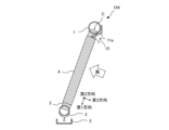
- FIG. 6 is a schematic side cross-sectional view showing a cross section of the second heat exchanger 154 according to Embodiment 2 as seen from the side.
- the same parts as in FIGS. 2 and 3 are given the same reference numerals, and different parts will be explained here.
- the flat tube 3 is arranged to be inclined with respect to the vertical direction.
- the first direction is the inclination direction of the flat tube 3 .
- the third direction is a direction orthogonal to the first direction and the second direction.
- the water conveying structure 12 is provided on the upper header 1 and has a first water conveying structure 11a.
- the first water guiding structure portion 11a is formed within the range of the angle formed by the first direction and the third direction orthogonal to the first direction and the second direction when the center C of the top header 1 is viewed from the second direction.
- the flat tube 3 of 1 covers part of the inclined side.
- the first water guiding structure 11 a guides the condensed water generated on the surface of the upper header 1 to the corrugated fins 4 .
- the first water guiding structure portion 11 a is provided in the upper header 1 on the front side with respect to the wind passing through the corrugated fins 4 .
- the first water guiding structure portion 11 a does not contact the corrugated fins 4 , but is arranged in the vicinity of the corrugated fins 4 to the extent that it can guide the condensed water to the corrugated fins 4 .
- the first water guiding structure portion 11a may come into contact with the corrugated fins 4 as in the first embodiment.
- the first water guiding structure portion 11a contacts the uppermost corrugated fin 4. As shown in FIG.
- the first direction which is the direction of inclination of the flat tube 3 with respect to the vertical direction, does not matter whether it is inclined forward with respect to the direction of the wind or is shown later. Also, the inclination angle of the flat tube 3 is not limited.
- FIG. 6 shows a state in which the first water conveying structure portion 11a is provided on the upper header 1 of the flat tube 3 tilted backward.
- FIG. 7 shows a state in which the first water conveying structure portion 11a is provided in the upper header 1 of the forward-inclined flat tube 3 in the second heat exchanger 154 according to the second embodiment.
- the first water conveying structure 11a is designed to prevent dewdrops from the upper header 1 due to gravity. It covers part of the bottom of the top header 1 .
- the first water guiding structure portion 11a may come into contact with the corrugated fins 4.
- the first water guiding structure portion 11a contacts the uppermost corrugated fin 4.
- the first water conveying structure portion 11a covers the lower side of the inclined upper header 1 . Therefore, it is possible to prevent the condensed water generated on the surface of the upper header 1 from dropping into the air passages of the corrugated fins 4 .
- FIG. 8 is a schematic side cross-sectional view showing a cross section of the second heat exchanger 154 according to Embodiment 3 as seen from the side.
- FIG. 9 is a diagram showing the first water conveying structure portion 11a of the second heat exchanger 154 according to the third embodiment. As shown in FIG. 9, the water guiding structure 12 has an L-shaped side surface and a comb-shaped lower end. A flat tube 3 is inserted and fixed between the comb-shaped comb teeth, and the lower end is in contact with the corrugated fins 4 .
- the first water guiding structure portion 11a When the center C of the upper header 1 is viewed from the second direction, the first water guiding structure portion 11a has an upper part over the entire range of angles formed by the first direction and a third direction perpendicular to the first and second directions.
- the end located on the heat transfer tube side is on a virtual line extending to the plus side of the first direction, or the virtual line and the third It is located in the area between the imaginary line extending on the negative side of the direction.
- the comb shape of the first water guiding structure 11a is such that the contact position between the first water guiding structure 11a and the corrugated fins 4 is on the windward side of the center of the upper header 1 with respect to the wind direction.
- FIG. 10 is a diagram showing the first water conveying structure portion 11a of the second heat exchanger 154 according to the modification of the third embodiment. As shown in FIG. 10, the first water conveying structure 11a is arranged across the heat exchangers 21a and 21b.
- the first water conveying structure 11a is provided on the upper header 1 of the heat exchanger 21a.
- the first water guiding structure portion 11a has an angle formed by a first direction and a third direction orthogonal to the first direction and the second direction when the center C of the upper header 1 of the heat exchanger 21a is viewed from the second direction. It covers part of the inclined side of the flat tube 3 of the upper header 1 within the range.
- the first water guiding structure portion 11 a guides the condensed water generated on the surface of the upper header 1 of the heat exchanger 21 a to the corrugated fins 4 .
- the first water guiding structure portion 11a is defined by a first direction and a third direction orthogonal to the first direction and the second direction when the center C of the upper header 1 of the heat exchanger 21b is viewed from the second direction.
- the flat tubes 3 of the upper header 1 cover part of the inclined side within the corners.
- the first water guiding structure 11 a guides the condensed water generated on the surface of the upper header 1 of the heat exchanger 21 b to the corrugated fins 4 .
- the condensed water generated in the upper header 1 can be more reliably conveyed to the surfaces of the corrugated fins 4. can be done.
- the side surface of the first water guiding structure portion 11a is L-shaped, the air passage passing between the upper header 1 and the corrugated fins 4 can be blocked. As a result, it is possible to suppress the formation of frost in the air passage caused by bypassing of the corrugated fins 4 by the humid air.
- the heat exchanger 21a and the heat exchanger 21b share one first water conveying structure portion 11a. Therefore, the number of manufactured first water conveying structure portions 11a is reduced, and the manufacturing cost can be reduced.
- Embodiment 4 the surfaces of the first water-conducting structure portion 11a and the second water-conducting structure portion 11b in Embodiment 1 are water-repellent surfaces. In Embodiment 4, the surfaces of the first water-conducting structure portion 11a and the second water-conducting structure portion 11b in Embodiments 2 and 3 are water-repellent surfaces. In Embodiment 4, the surfaces of the corrugated fins 4 in Embodiments 1, 2 and 3 are made hydrophilic.
- FIG. 11 is a diagram for explaining the contact angle ⁇ . As shown in FIG. 11, the contact angle ⁇ is the angle between the solid surface rSL and the droplet surface rLV.
- the water-repellent surface has a contact angle ⁇ of 90° or more.
- the hydrophilic surface has a contact angle ⁇ of 40° or less, ideally 10° or less.
- the droplet has a wettability gradient that changes the contact angle ⁇ , a driving force is generated and it has the property of moving from the water-repellent surface to the hydrophilic surface. Therefore, according to the fourth embodiment, the condensed water is easily guided from the first water conveying structure portion 11a or the second water conveying structure portion 11b toward the corrugated fins 4.
- FIG. 12 is a view showing the first water conveying structure portion 11a provided in the first row heat exchanger 22a and the second row heat exchanger 22b arranged in the third direction of the second heat exchanger 154 according to the fifth embodiment.
- . 13 is a schematic top cross-sectional view showing the AA' cross section of FIG. 12.
- FIG. 13 for the sake of explanation, the position where the first water conveying structure 11a is arranged is indicated by oblique lines.
- the same parts as in FIGS. 2 and 3 are given the same reference numerals, and different parts will be explained here.
- FIG. 12 shows one inclined first row heat exchanger 22a and a second row heat exchanger 22b arranged in parallel in the third direction of the first row heat exchanger 22a.
- FIG. 13 shows the second heat exchanger 154 with two rows and two columns.
- inter-row water conduction holes 31 are provided between the flat tubes 3 of the first row heat exchanger 22a and the flat tubes 3 of the second row heat exchanger 22b.
- the flat tubes 3 of the first row heat exchanger 22a are also called first row heat transfer tubes
- the flat tubes 3 of the second row heat exchanger 22b are also called second row heat transfer tubes.
- the first water guiding structure portion 11 a extends toward the inter-row water guiding holes 31 .
- the corrugated fins 4 are integrally provided between the flat tubes 3 of the first row heat exchanger 22a and the flat tubes 3 of the second row heat exchanger 22b.
- the corrugated fins 4 may be separately provided on the flat tubes 3 of the first row heat exchanger 22a and the flat tubes 3 of the second row heat exchanger 22b.
- the inter-row water guide holes 31 may be provided in the corrugated fins 4 .
- the first water conveying structure portion 11a is provided so as to extend toward the inter-row water conveying holes 31 . Therefore, according to the second heat exchanger 154 according to the fifth embodiment, the condensed water can be discharged more efficiently than through the drainage channels on the corrugated fins 4 .
- FIG. 14 is a schematic side cross-sectional view showing a cross section of the second heat exchanger 154 according to Embodiment 6 as seen from the side.
- the same parts as in FIGS. 2 and 3 are given the same reference numerals, and different parts will be explained here.
- a thermally insulating portion 41 is provided between the first water conveying structure portion 11a and the upper header 1 of the second heat exchanger 154 according to the sixth embodiment.
- a heat insulating portion 41 is provided between the second water conveying structure portion 11 b and the upper header 1 .
- the heat insulation processing part 41 is, for example, one or both of a heat insulation sheet and a hollow structure.
- the heat insulating treatment portion 41 is provided, so that the upper header 1 It is possible to further suppress the air from being cooled and condensed on the surface of the .
Abstract
熱交換器は、各々が第1方向に延び、第1方向に直交する第2方向に配列された複数の伝熱管と、伝熱管の上端に設けられ、第2方向に延びる上部ヘッダと、上部ヘッダの中心を第2方向から見て、第1方向と、第1方向及び第2方向とに直交する第3方向とが成す角の範囲内で上部ヘッダの一部を覆い、上部ヘッダの表面に発生した結露水を複数の伝熱管の間に導く導水構造部とを具備する。
Description
本開示は、導水構造部を有する熱交換器に関する。
鉛直方向に対して扁平管が傾斜して配置されるパラレルフロー型熱交換器がある。このようなパラレルフロー型熱交換器において、上部ヘッダの最下部から扁平管に向かう平板を設け、上部ヘッダからの結露水の飛び出しを抑制する構成が知られている(例えば、特許文献1参照)。
特許文献1に示された熱交換器では、平板は上部ヘッダ表面を覆うように取り付けられているのみで、結露水が熱交換器に導かれず、平板の外側から結露水が飛散し、露だれの可能性がある。
本開示は、上記実情に鑑みてなされたものであり、ヘッダからの結露水の露だれを抑制することができる熱交換器を提供することを目的とする。
本開示に係る熱交換器は、各々が第1方向に延び、前記第1方向に直交する第2方向に配列された複数の伝熱管と、前記伝熱管の上端に設けられ、前記第2方向に延びる上部ヘッダと、前記上部ヘッダの中心を前記第2方向から見て、前記第1方向と、前記第1方向及び前記第2方向とに直交する第3方向とが成す角の範囲内で前記上部ヘッダの一部を覆い、前記上部ヘッダの表面に発生した結露水を前記複数の伝熱管の間に導く導水構造部とを具備する。
本開示によれば、導水構造部が第3方向と第1方向となす角の範囲内で上部ヘッダの下部の一部を覆い、上部ヘッダの表面に発生した結露水を複数の伝熱管の間に導くことができる。
以下、図面を参照して、実施形態に係る空気調和装置について説明する。なお、図面において、同一の構成要素には同一符号を付して説明し、重複説明は必要な場合にのみ行なう。本開示は、以下の各実施形態で説明する構成のうち、組合せ可能な構成のあらゆる組合せを含み得る。また、図面では各構成部材の大きさの関係が実際のものとは異なる場合がある。そして、明細書全文に表わされている構成要素の形態は、あくまでも例示であって、明細書に記載された形態に限定するものではない。
実施形態1.
図1は、実施形態1に係る冷凍サイクル装置200の冷媒回路構成を概略的に示す冷媒回路図である。図1に基づいて、冷凍サイクル装置200の構成及び動作について説明する。実施形態1に係る冷凍サイクル装置200は、第1冷媒分配器152aを備えた第1熱交換器152及び第2冷媒分配器154aを備えた第2熱交換器154を冷媒回路の一要素として備えたものである。
図1は、実施形態1に係る冷凍サイクル装置200の冷媒回路構成を概略的に示す冷媒回路図である。図1に基づいて、冷凍サイクル装置200の構成及び動作について説明する。実施形態1に係る冷凍サイクル装置200は、第1冷媒分配器152aを備えた第1熱交換器152及び第2冷媒分配器154aを備えた第2熱交換器154を冷媒回路の一要素として備えたものである。
<冷凍サイクル装置200の構成>
図1に示すように、冷凍サイクル装置200は、室外機101と室内機102とを有する。室外機101は、圧縮機100、流路切替装置151、第1熱交換器152及び膨張装置153を有する。また、圧縮機100の上流側にはアキュームレータ300が配置されている。第1熱交換器152には、第1冷媒分配器152aが設けられている。第1冷媒分配器152aは、第1熱交換器152の伝熱管に冷媒を分配する。第1熱交換器152の近傍には、室外ファン156が設けられている。さらに、室外機101は制御装置160を有する。
図1に示すように、冷凍サイクル装置200は、室外機101と室内機102とを有する。室外機101は、圧縮機100、流路切替装置151、第1熱交換器152及び膨張装置153を有する。また、圧縮機100の上流側にはアキュームレータ300が配置されている。第1熱交換器152には、第1冷媒分配器152aが設けられている。第1冷媒分配器152aは、第1熱交換器152の伝熱管に冷媒を分配する。第1熱交換器152の近傍には、室外ファン156が設けられている。さらに、室外機101は制御装置160を有する。
室内機102は、第2熱交換器154を有する。第2熱交換器154には、第2冷媒分配器154aが設けられている。第2冷媒分配器154aは、第2熱交換器154の図示せぬ伝熱管に冷媒を分配する。第2熱交換器154の近傍には、室内ファン157が設けられている。
圧縮機100、第1熱交換器152及び膨張装置153が配管155aにより配管接続され、膨張装置153、第2熱交換器154及び圧縮機100が、配管155bにより配管接続されて冷媒回路を形成している。
圧縮機100は、吸入された冷媒を圧縮して高温高圧の状態とするものである。圧縮機100で圧縮された冷媒は、圧縮機100から吐出されて第1熱交換器152又は第2熱交換器154へ送られる。
流路切替装置151は、暖房運転と冷房運転とにおいて冷媒の流れを切り替えるものである。流路切替装置151は、暖房運転時には圧縮機100と第2熱交換器154とを接続するように切り替えられ、冷房運転時には圧縮機100と第1熱交換器152とを接続するように切り替えられる。なお、流路切替装置151は、たとえば四方弁で構成するとよい。ただし、二方弁又は三方弁の組み合わせを流路切替装置151として採用してもよい。
第1熱交換器152は、暖房運転時には蒸発器として機能し、冷房運転時には凝縮器として機能する。蒸発器として機能する場合、第1熱交換器152では、膨張装置153から流出された低温低圧の冷媒と、室外ファン156により供給される空気とが熱交換され、低温低圧の気液二相冷媒の液冷媒が蒸発する。一方、凝縮器として機能する場合、第1熱交換器152では、圧縮機100から吐出された高温高圧の冷媒と、室外ファン156により供給される空気とが熱交換され、高温高圧のガス冷媒が凝縮される。なお、第1熱交換器152を、冷媒-水熱交換器で構成してもよい。この場合、第1熱交換器152では、冷媒と、水などの熱媒体とで熱交換が実行される。
膨張装置153は、第1熱交換器152又は第2熱交換器154から流出した冷媒を膨張させて減圧するものである。膨張装置153は、例えば冷媒の流量を調整可能な電動膨張弁等で構成するとよい。なお、膨張装置153としては、電動膨張弁だけでなく、受圧部にダイアフラムを採用した機械式膨張弁、又は、キャピラリーチューブ等を適用することも可能である。
第2熱交換器154は、暖房運転時には凝縮器として機能し、冷房運転時には蒸発器として機能するものである。凝縮器として機能する場合、第2熱交換器154では、圧縮機100から吐出された高温高圧の冷媒と、室内ファン157により供給される空気とが熱交換され、高温高圧のガス冷媒が凝縮される。一方、蒸発器として機能する場合、第2熱交換器154では、膨張装置153から流出された低温低圧の冷媒と、室内ファン157により供給される空気とが熱交換され、気液二相冷媒の低温低圧の液冷媒が蒸発する。なお、第2熱交換器154を、冷媒-水熱交換器で構成してもよい。この場合、第2熱交換器154では、冷媒と、水などの熱媒体とで熱交換が実行される。
第1冷媒分配器152aは、第1熱交換器152の複数の伝熱管に冷媒を分配する。室外ファン156は、第1熱交換器152に熱交換のための空気を送風する。第2冷媒分配器154aは、第2熱交換器154の図示せぬ伝熱管に冷媒を分配する。室内ファン157は、第2熱交換器154に熱交換のための空気を送風する。
制御装置160は、冷凍サイクル装置200全体を統括制御する。具体的には、制御装置160は、必要とする冷却能力又は加熱能力に応じて圧縮機100の駆動周波数を制御する。また、制御装置160は、運転状態及びモード毎に応じて膨張装置153の開度を制御する。さらに、制御装置160は、モード毎に応じて流路切替装置151を制御する。
制御装置160は、ユーザーからの運転指示に基づいて、図示省略の各温度センサー及び図示省略の各圧力センサーから送られる情報を利用し、例えば、圧縮機100、膨張装置153及び流路切替装置151等の各アクチュエーターを制御する。
なお、制御装置160は、その機能を実現する回路デバイスのようなハードウェアで構成することもできるし、マイコン又はCPUのような演算装置と、その上で実行されるソフトウェアとにより構成することもできる。
制御装置160は、専用のハードウェア、又はメモリに格納されるプログラムを実行するCPU(Central Processing Unit、中央処理装置、処理装置、演算装置、マイクロプロセッサ、マイクロコンピュータ、プロセッサともいう)で構成される。制御装置160が専用のハードウェアである場合、制御装置160は、例えば、単一回路、複合回路、ASIC(Application Specific Integrated Circuit)、FPGA(Field Programmable Gate Array)、又はこれらを組み合わせたものが該当する。制御装置160が実現する各機能部のそれぞれを、個別のハードウェアで実現してもよいし、各機能部を一つのハードウェアで実現してもよい。制御装置160がCPUの場合、制御装置160が実行する各機能は、ソフトウェア、ファームウェア、又はソフトウェアとファームウェアとの組み合わせにより実現される。ソフトウェア及びファームウェアはプログラムとして記述され、メモリに格納される。CPUは、メモリに格納されたプログラムを読み出して実行し、制御装置160の各機能を実現する。ここで、メモリは、例えば、RAM、ROM、フラッシュメモリ、EPROM、EEPROM等の、不揮発性又は揮発性の半導体メモリである。なお、制御装置160の機能の一部を専用のハードウェアで実現し、一部をソフトウェア又はファームウェアで実現するようにしてもよい。
なお、図1においては、第1熱交換器152に第1冷媒分配器152aが設けられ、第2熱交換器154に第2冷媒分配器154aが設けられている場合を示しているが、いずれか一方にのみに冷媒分配器が設けられていても良い。
<冷凍サイクル装置200の動作>
次に、冷凍サイクル装置200の動作について、冷媒の流れとともに説明する。ここでは、第1熱交換器152及び第2熱交換器154での熱交換流体が空気である場合を例に、冷凍サイクル装置200の冷房運転時の動作について説明する。なお、図1では、冷房運転時の冷媒の流れを破線矢印で示し、暖房運転時の冷媒の流れを実線矢印で示している。
次に、冷凍サイクル装置200の動作について、冷媒の流れとともに説明する。ここでは、第1熱交換器152及び第2熱交換器154での熱交換流体が空気である場合を例に、冷凍サイクル装置200の冷房運転時の動作について説明する。なお、図1では、冷房運転時の冷媒の流れを破線矢印で示し、暖房運転時の冷媒の流れを実線矢印で示している。
圧縮機100が駆動され、圧縮機100から高温高圧のガス状態の冷媒が吐出される。圧縮機100から吐出された高温高圧のガス冷媒(単相)は、第1熱交換器152に流れ込む。第1熱交換器152では、流れ込んだ高温高圧のガス冷媒と、室外ファン156によって供給される空気との間で熱交換が行われて、高温高圧のガス冷媒は、凝縮されて高圧の液冷媒(単相)になる。
第1熱交換器152から送り出された高圧の液冷媒は、膨張装置153によって、低圧のガス冷媒と液冷媒との二相状態の冷媒になる。気液二相状態の冷媒は、第2冷媒分配器154aにより収集され、収集された気液二相状態の冷媒は第2熱交換器154に流れ込む。第2熱交換器154では、第2冷媒分配器154aにより分配され、流れ込んだ気液二相状態の冷媒と、室内ファン157によって供給される空気との間で熱交換が行われて、気液二相状態の冷媒のうち液冷媒が蒸発して低圧であって単相のガス冷媒になる。第2熱交換器154から送り出された低圧のガス冷媒は、アキュームレータ300を介して圧縮機100に流れ込み、圧縮されて高温高圧のガス冷媒となって、再び圧縮機100から吐出される。以降、このサイクルが繰り返される。
なお、冷凍サイクル装置200の暖房運転時の動作は、流路切替装置151により冷媒の流れを図1に示す実線矢印の流れにすることで実行される。
また、圧縮機100の吐出側に設けた流路切替装置151を設けずに、冷媒の流れを一定方向にしてもよい。
冷凍サイクル装置200が冷房専用又は暖房専用であって冷媒の流れ方向を切り替える必要が無い場合には、流路切替装置151を設けなくてよい。
さらに、冷凍サイクル装置200の適用例としては、空気調和装置の他、給湯器、冷凍機、又は空調給湯複合機などがある。
<第2熱交換器154>
図2は、実施形態1に係る冷凍サイクル装置200における第2熱交換器154を正面から見た断面を示す断面模式図である。図3は、実施形態1に係る第2熱交換器154を側面から見た断面を示す側面断面模式図である。
図2は、実施形態1に係る冷凍サイクル装置200における第2熱交換器154を正面から見た断面を示す断面模式図である。図3は、実施形態1に係る第2熱交換器154を側面から見た断面を示す側面断面模式図である。
図2及び図3においては、第2熱交換器154を示したが、第1熱交換器152も第2熱交換器154と同様の構成が採用されても良い。
図2及び図3に示すように、第2熱交換器154は、上部ヘッダ1、下部ヘッダ2、扁平管3、コルゲートフィン4、ドレンパン5及び導水構造部12を有する。
扁平管3は、鉛直方向(重力方向)である第1方向に延びる。実施形態1においては、第1方向は鉛直方向である。図では、矢印の指す向きが、第1方向のプラス側に相当する。
上部ヘッダ1及び下部ヘッダ2は、第1方向に直交する第2方向に延びるように配置される。扁平管3は、第2方向に間隔を空けて設けられ、一端が上部ヘッダ1に挿入され、他端が下部ヘッダ2に挿入される。冷媒の流れ方向は特に規定しないが、図2では蒸発運転時に、冷媒が下部ヘッダ2から上部ヘッダ1に向かって流れる。ガスヘッダとなる上部ヘッダ1の外径は内部流動時の冷媒圧損を抑制するため、下部ヘッダ2の外径と比べて多きい。従って、上部ヘッダ1からの露だれが起こり易い。なお、上部ヘッダ1及び下部ヘッダ2の形状は円筒型のほか、断面D型の筒型であっても良い。
コルゲートフィン4、隣接する扁平管3の間に位置するように扁平管3に取り付けられる。コルゲートフィン4は、第1方向に直交する第2方向に延びる。コルゲートフィン4は扁平管3に伝熱を行なう。コルゲートフィン4は、第1方向に向かって排水を行なうことができるルーバー構造である。なお、扁平管3に取り付けられるフィンの形状は、コルゲートフィンに限定されない。
ドレンパン5は、第2熱交換器154が配置された状態において、下部ヘッダ2の下側に配置される。ドレンパン5は、上部ヘッダ1の表面に付着して導水構造部12を介して滴下する結露水を上面で受け取る。
導水構造部12は、上部ヘッダ1に設けられ、第1導水構造部11a及び第2導水構造部11bを有する。第1導水構造部11a及び第2導水構造部11bは、例えば樹脂のような別体部品で構成される。
第1導水構造部11aは、上部ヘッダ1の中心Cを第2方向から見て、第1方向と、第1方向及び第2方向とに直交する第3方向とが成す角の範囲内で上部ヘッダ1の一部を覆う。図では、矢印の指す向きが、第3方向のプラス側に相当する。ここで、上部ヘッダ1の中心Cとは、上部ヘッダ1の流路断面の中心をいう。第1導水構造部11aは、上部ヘッダ1の表面に発生した結露水をコルゲートフィン4に導く。第1導水構造部11aは、コルゲートフィン4を通過する風に対して前面側の上部ヘッダ1に設けられる。第1導水構造部11aは、コルゲートフィン4に接触しないが、結露水をコルゲートフィン4に導くことができる程度のコルゲートフィン4の近傍に配置される。
第1導水構造部11aは、上部ヘッダ1の中心Cを第2方向から見て、第1方向と、第1方向及び第2方向に直交する第3方向とが成す角の全ての範囲において上部ヘッダ1を覆い、かつ上部ヘッダ1の中心Cを第2方向から見て、伝熱管側に位置する端部が、前記第1方向のプラス側に延びる仮想線上、又は前記仮想線と前記第3方向のマイナス側に延びる仮想線との間の領域に位置している(例えば、図8参照)。
第2導水構造部11bは、上部ヘッダ1の中心Cを第2方向から見て、第1方向と、第1方向及び第2方向とに直交する第3方向とが成す角の範囲内で上部ヘッダ1の一部を覆う。第2導水構造部11bは、上部ヘッダ1の表面に発生した結露水をコルゲートフィン4に導く。第2導水構造部11bは、コルゲートフィン4を通過する風に対して後面側の上部ヘッダ1に設けられる。第2導水構造部11bは、コルゲートフィン4に接触しないが、結露水をコルゲートフィン4に導くことができる程度のコルゲートフィン4の近傍に配置される。
図4は、実施形態1の変形例に係る冷凍サイクル装置200における第2熱交換器154を正面から見た断面を示す断面模式図である。図5は、実施形態1の変形例に係る第2熱交換器154を側面から見た断面を示す側面断面模式図である。第1導水構造部11a及び第2導水構造部11bは、図4及び図5に示すように、コルゲートフィン4に接触する。第1導水構造部11a及び第2導水構造部11bは、最上段のコルゲートフィン4に接触する。
第1導水構造部11a及び第2導水構造部11bは、図5に示すように、第2熱交換器154を側面から見た場合に、略L字形状で示したが、半円形状などの他の形状であっても良い。
上部ヘッダ1の表面にて発生した結露水は、第1導水構造部11a及び第2導水構造部11bによりコルゲートフィン4に導かれる。コルゲートフィン4に導かれた結露水は、コルゲートフィン4を通過する風と熱交換されるとともに、一部は、第1方向に向かって排水される。コルゲートフィン4から排水された結露水は、扁平管3の表面を伝わり、下部ヘッダ2からドレンパン5に滴下する。
実施形態1の第2熱交換器154によれば、導水構造部12により上部ヘッダ1の表面で発生する結露水をコルゲートフィン4に導くことができるので、結露水が上部ヘッダ1から風路に出てしまうことを抑制できる。その結果、上部ヘッダ1の表面にて発生した結露水の露だれを抑制することができる。
実施形態1の変形例の第2熱交換器154によれば、図5に示すように、第1導水構造部11a及び第2導水構造部11bと、コルゲートフィン4とを接触する。このため、第1導水構造部11a及び第2導水構造部11bで受けた結露水を、より確実にコルゲートフィン4に導くことができる。また、コルゲートフィン4と上部ヘッダ1との間が第1導水構造部11a及び第2導水構造部11bによって塞がれるので、コルゲートフィン4と上部ヘッダ1との間に風が流れることを抑制できる。その結果、多湿空気が第2熱交換器154の下流の風路へ抜けてしまうことによる、下流の風路での結露を抑制できる。
実施形態2.
実施形態1では、第2熱交換器154が鉛直に設けられている場合について説明した。実施形態2では、第2熱交換器154が鉛直方向に対して傾くように配置されている。
実施形態1では、第2熱交換器154が鉛直に設けられている場合について説明した。実施形態2では、第2熱交換器154が鉛直方向に対して傾くように配置されている。
図6は、実施形態2に係る第2熱交換器154を側面から見た断面を示す側面断面模式図である。なお、図2及び図3と同一部分には同一符号を付し、ここでは異なる部分について説明する。
図6に示すように、扁平管3は、鉛直方向に対して傾斜して配置される。実施形態2においては、第1方向は、扁平管3の傾斜方向である。また、図5に示すように、第3方向は、第1方向及び第2方向とに直交する方向である。
導水構造部12は、上部ヘッダ1に設けられ、第1導水構造部11aを有する。第1導水構造部11aは、上部ヘッダ1の中心Cを第2方向から見て、第1方向と、第1方向及び第2方向に直交する第3方向とが成す角の範囲内で上部ヘッダ1の扁平管3が傾斜している側の一部を覆う。第1導水構造部11aは、上部ヘッダ1の表面に発生した結露水をコルゲートフィン4に導く。第1導水構造部11aは、コルゲートフィン4を通過する風に対して前面側の上部ヘッダ1に設けられる。第1導水構造部11aは、コルゲートフィン4に接触しないが、結露水をコルゲートフィン4に導くことができる程度のコルゲートフィン4の近傍に配置される。
第1導水構造部11aは、実施形態1と同様に、コルゲートフィン4に接触しても良い。第1導水構造部11aは、最上段のコルゲートフィン4に接触する。
扁平管3の鉛直方向に対する傾斜方向である第1方向は、風向きに対して前傾であるか、後掲であるかを問わない。また、扁平管3の傾斜角度についても問わない。図6は、後傾である扁平管3の上部ヘッダ1に第1導水構造部11aが設けられている状態を示す。
図7は、実施形態2に係る第2熱交換器154における前傾の扁平管3の上部ヘッダ1に第1導水構造部11aが設けられている状態を示す。図6及び図7に示すように、扁平管3が前傾又は後傾であっても、第1導水構造部11aは、重力で上部ヘッダ1から露だれが発生することを防止するために、上部ヘッダ1の下部の一部を覆う。
図7に示す場合であっても第1導水構造部11aは、コルゲートフィン4に接触しても良い。第1導水構造部11aは、最上段のコルゲートフィン4に接触する。
実施形態2によれば、第2熱交換器154が傾斜して配置されていたとしても、第1導水構造部11aは傾斜している上部ヘッダ1の下側を覆う。従って、上部ヘッダ1の表面で発生した結露水がコルゲートフィン4の風路へ落下することを抑制できる。
実施形態3.
図8は、実施形態3に係る第2熱交換器154を側面から見た断面を示す側面断面模式図である。図9は、実施形態3に係る第2熱交換器154の第1導水構造部11aを示す図である。図9に示すように、導水構造部12は、側面がL字形状であり、下端が櫛歯形状である。この櫛歯形状の櫛歯間には扁平管3が差し込まれて固定され、下端がコルゲートフィン4に接する。
図8は、実施形態3に係る第2熱交換器154を側面から見た断面を示す側面断面模式図である。図9は、実施形態3に係る第2熱交換器154の第1導水構造部11aを示す図である。図9に示すように、導水構造部12は、側面がL字形状であり、下端が櫛歯形状である。この櫛歯形状の櫛歯間には扁平管3が差し込まれて固定され、下端がコルゲートフィン4に接する。
第1導水構造部11aは、上部ヘッダ1の中心Cを第2方向から見て、第1方向と、第1方向及び第2方向に直交する第3方向とが成す角の全ての範囲において上部ヘッダ1を覆い、かつ上部ヘッダ1の中心Cを第2方向から見て、伝熱管側に位置する端部が、前記第1方向のプラス側に延びる仮想線上、又は前記仮想線と前記第3方向のマイナス側に延びる仮想線との間の領域に位置している。
第1導水構造部11aの櫛歯形状は、第1導水構造部11aとコルゲートフィン4との接触位置が、風向きに対して上部ヘッダ1の中央よりも風上側になるような形状である。このような櫛歯形状を有する第1導水構造部11aを使用することにより、導水構造部12を流れる結露水が風下側へ出にくくなる。
図10は、実施形態3の変形例に係る第2熱交換器154の第1導水構造部11aを示す図である。図10に示すように、第1導水構造部11aは熱交換器21a及び熱交換器21bをまたぐように配置される。
第1導水構造部11aは、熱交換器21aの上部ヘッダ1に設けられる。第1導水構造部11aは、熱交換器21aの上部ヘッダ1の中心Cを第2方向から見て、第1方向と、第1方向及び第2方向に直交する第3方向とが成す角の範囲内で上部ヘッダ1の扁平管3が傾斜している側の一部を覆う。第1導水構造部11aは、熱交換器21aの上部ヘッダ1の表面に発生した結露水をコルゲートフィン4に導く。また、第1導水構造部11aは、熱交換器21bの上部ヘッダ1の中心Cを第2方向から見て、第1方向と、第1方向及び第2方向に直交する第3方向とが成す角の範囲内で上部ヘッダ1の扁平管3が傾斜している側の一部を覆う。第1導水構造部11aは、熱交換器21bの上部ヘッダ1の表面に発生した結露水をコルゲートフィン4に導く。
実施形態3に係る第2熱交換器154によれば、第1導水構造部11aがコルゲートフィン4に接するので、上部ヘッダ1で発生した結露水をより確実にコルゲートフィン4の表面に導水することができる。
また、第1導水構造部11aの側面がL字形状であるので、上部ヘッダ1とコルゲートフィン4との間を通過する風路を塞ぐことができる。その結果、多湿空気がコルゲートフィン4を通らずバイパスすることで生ずる風路での霜付きを抑制することができる。
実施形態3の変形例に係る第2熱交換器154の第1導水構造部11aによれば、熱交換器21a及び熱交換器21bで1つの第1導水構造部11aを共有する。従って、第1導水構造部11aの製造数が少なくなり、製造コストを低減できる。
実施形態4.
実施形態4においては、実施形態1における第1導水構造部11a及び第2導水構造部11bの表面を撥水面とする。実施形態4においては、実施形態2及び実施形態3における第1導水構造部11a及び第2導水構造部11bの表面を撥水面とする。実施形態4においては、実施形態1、実施形態2及び実施形態3におけるコルゲートフィン4の表面を親水面とする。
実施形態4においては、実施形態1における第1導水構造部11a及び第2導水構造部11bの表面を撥水面とする。実施形態4においては、実施形態2及び実施形態3における第1導水構造部11a及び第2導水構造部11bの表面を撥水面とする。実施形態4においては、実施形態1、実施形態2及び実施形態3におけるコルゲートフィン4の表面を親水面とする。
表面が撥水面又は親水面であるかは接触角θで判断される。図11は、接触角θを説明するための図である。図11に示すように、接触角θは、固体表面rSLと液滴表面rLVとがなす角である。撥水面は、接触角θが90°以上である。親水面は、接触角θが40°以下であり、理想的には10°以下である。
液滴は接触角θが変化する濡れ性勾配があると駆動力が生じ、撥水面から親水面に向かって移動する性質を持つ。従って、実施形態4によれば、第1導水構造部11a又は第2導水構造部11bからコルゲートフィン4に向かって結露水が導水し易くなる。
実施形態5.
図12は、実施形態5に係る第2熱交換器154の第3方向に並ぶ第1列熱交換器22a及び第2列熱交換器22bに設けられる第1導水構造部11aを示す図である。図13は、図12のA-A’断面を示す上面断面模式図である。図13では、説明のため、第1導水構造部11aが配置される位置を斜線で示している。なお、図2及び図3と同一部分には同一符号を付し、ここでは異なる部分について説明する。
図12は、実施形態5に係る第2熱交換器154の第3方向に並ぶ第1列熱交換器22a及び第2列熱交換器22bに設けられる第1導水構造部11aを示す図である。図13は、図12のA-A’断面を示す上面断面模式図である。図13では、説明のため、第1導水構造部11aが配置される位置を斜線で示している。なお、図2及び図3と同一部分には同一符号を付し、ここでは異なる部分について説明する。
図12は、1つの傾斜して配置された第1列熱交換器22aと、第1列熱交換器22aの第3方向に並列に配置された第2列熱交換器22bとを示している。図13は、2行2列の第2熱交換器154を示している。
図12及び図13に示すように、第1列熱交換器22aの扁平管3と、第2列熱交換器22bの扁平管3との間には、列間導水穴31が設けられている。第1列熱交換器22aの扁平管3は第1列伝熱管とも称し、第2列熱交換器22bの扁平管3は第2列伝熱管とも称する。図12に示すように、第1導水構造部11aは、列間導水穴31に向かって伸びている。
図12に示すように、コルゲートフィン4は、第1列熱交換器22aの扁平管3と第2列熱交換器22bの扁平管3との間に一体に設けられている。コルゲートフィン4は、第1列熱交換器22aの扁平管3と第2列熱交換器22bの扁平管3とに別々に設けられても良い。また、列間導水穴31は、コルゲートフィン4に設けられていても良い。
実施形態5に係る第2熱交換器154では、第1導水構造部11aが列間導水穴31に向かって延びるように設けられている。従って、実施形態5に係る第2熱交換器154によれば、結露水をコルゲートフィン4上の排水路を通して排出するよりも効率的に排出することができる。
実施形態6.
図14は、実施形態6に係る第2熱交換器154を側面から見た断面を示す側面断面模式図である。なお、図2及び図3と同一部分には同一符号を付し、ここでは異なる部分について説明する。
図14は、実施形態6に係る第2熱交換器154を側面から見た断面を示す側面断面模式図である。なお、図2及び図3と同一部分には同一符号を付し、ここでは異なる部分について説明する。
図14に示すように、実施形態6に係る第2熱交換器154の第1導水構造部11aと上部ヘッダ1との間には断熱処理部41が設けられる。第2導水構造部11bと上部ヘッダ1との間には断熱処理部41が設けられる。断熱処理部41は、例えば、断熱シート及び中空構造のいずれか又は両方である。
実施形態2に示すように、第2熱交換器154が傾斜して配置される場合であって、第1導水構造部11aのみが設けられる場合には、第1導水構造部11aと上部ヘッダ1との間に断熱処理部41が設けられる。
実施形態6の第2熱交換器154によれば、第1導水構造部11a及び第2導水構造部11bに多湿空気が当たる際に、断熱処理部41が設けられていることから、上部ヘッダ1の表面で空気が冷却され結露することをさらに抑制することができる。
1 上部ヘッダ、2 下部ヘッダ、3 扁平管、4 コルゲートフィン、5 ドレンパン、11a 第1導水構造部、11b 第2導水構造部、12 導水構造部、21a、21b 熱交換器、22a、22b 列熱交換器、31 列間導水穴、41 断熱処理部、100 圧縮機、101 室外機、102 室内機、151 流路切替装置、152 第1熱交換器、152a 第1冷媒分配器、153 膨張装置、154 第2熱交換器、154a 第2冷媒分配器、155a、155b 配管、156 室外ファン、157 室内ファン、160 制御装置、200 冷凍サイクル装置、300 アキュームレータ、C 上部ヘッダの中心、t 端部。
Claims (8)
- 各々が第1方向に延び、前記第1方向に直交する第2方向に配列された複数の伝熱管と、
前記伝熱管の上端に設けられ、前記第2方向に延びる上部ヘッダと、
前記上部ヘッダの中心を前記第2方向から見て、前記第1方向と、前記第1方向及び前記第2方向とに直交する第3方向とが成す角の範囲内で前記上部ヘッダの一部を覆い、前記上部ヘッダの表面に発生した結露水を前記複数の伝熱管の間に導く導水構造部と
を具備する熱交換器。 - 各々が第1方向に延び、前記第1方向に直交する第2方向に配列された複数の伝熱管と、
前記伝熱管の上端に設けられ、前記第2方向に延びる上部ヘッダと、
前記上部ヘッダの中心を前記第2方向から見て、前記第1方向と、前記第1方向及び前記第2方向に直交する第3方向とが成す角の全ての範囲において前記上部ヘッダを覆い、かつ前記上部ヘッダの中心を前記第2方向から見て、前記伝熱管側に位置する端部が、前記第1方向のプラス側に延びる仮想線上、又は前記仮想線と前記第3方向のマイナス側に延びる仮想線との間の領域に位置している導水構造部と
を具備する熱交換器。 - 前記伝熱管に設けられたフィンを具備し、
前記導水構造部は、前記フィンに接触する
請求項1又は2に記載の熱交換器。 - 前記複数の伝熱管は、鉛直方向に対して傾斜して配置され、
前記導水構造部が覆っている前記上部ヘッダの前記一部は、前記上部ヘッダの下側である
請求項1~3のいずれか1項に記載の熱交換器。 - 前記導水構造部は、前記複数の伝熱管の間に挿し込まれ、下端が前記フィンに接する櫛歯形状である
請求項3に記載の熱交換器。 - 前記導水構造部の表面は撥水面であり、前記フィンの表面は親水面である
請求項3又は5のいずれか1項に記載の熱交換器。 - 前記複数の伝熱管は、前記第3方向に沿って配置された第1列伝熱管と第2列伝熱管とを含み、
前記導水構造部は、前記第1列伝熱管と、前記第2列伝熱管との間の列間導水穴に向かって伸びている
請求項1~6のいずれか1項に記載の熱交換器。 - 前記導水構造部と前記上部ヘッダとの間に設けられた断熱処理部を具備する
請求項1~7のいずれか1項に記載の熱交換器。
Priority Applications (1)
| Application Number | Priority Date | Filing Date | Title |
|---|---|---|---|
| PCT/JP2022/003484 WO2023145042A1 (ja) | 2022-01-31 | 2022-01-31 | 熱交換器 |
Applications Claiming Priority (1)
| Application Number | Priority Date | Filing Date | Title |
|---|---|---|---|
| PCT/JP2022/003484 WO2023145042A1 (ja) | 2022-01-31 | 2022-01-31 | 熱交換器 |
Publications (1)
| Publication Number | Publication Date |
|---|---|
| WO2023145042A1 true WO2023145042A1 (ja) | 2023-08-03 |
Family
ID=87470916
Family Applications (1)
| Application Number | Title | Priority Date | Filing Date |
|---|---|---|---|
| PCT/JP2022/003484 WO2023145042A1 (ja) | 2022-01-31 | 2022-01-31 | 熱交換器 |
Country Status (1)
| Country | Link |
|---|---|
| WO (1) | WO2023145042A1 (ja) |
Citations (9)
| Publication number | Priority date | Publication date | Assignee | Title |
|---|---|---|---|---|
| JPH0612425Y2 (ja) * | 1990-01-18 | 1994-03-30 | ピーエス工業株式会社 | 冷房用熱交換器 |
| JPH07172152A (ja) * | 1993-05-19 | 1995-07-11 | Nippondenso Co Ltd | 空気調和装置のクーリングユニットおよび排水ケース |
| JP2002213840A (ja) * | 2001-01-19 | 2002-07-31 | Denso Corp | 蒸発器 |
| JP2004316976A (ja) * | 2003-04-14 | 2004-11-11 | Japan Climate Systems Corp | 熱交換器 |
| KR20100097344A (ko) * | 2009-02-26 | 2010-09-03 | 한라공조주식회사 | 배수성 향상된 자동차용 공조장치 |
| JP2015222146A (ja) * | 2014-05-23 | 2015-12-10 | パナソニックIpマネジメント株式会社 | 熱交換器 |
| JP2015224844A (ja) * | 2014-05-29 | 2015-12-14 | パナソニックIpマネジメント株式会社 | 熱交換器 |
| JP2015227754A (ja) * | 2014-06-02 | 2015-12-17 | パナソニックIpマネジメント株式会社 | 熱交換器 |
| JP2016020759A (ja) * | 2014-07-14 | 2016-02-04 | カルソニックカンセイ株式会社 | 熱交換器 |
-
2022
- 2022-01-31 WO PCT/JP2022/003484 patent/WO2023145042A1/ja unknown
Patent Citations (9)
| Publication number | Priority date | Publication date | Assignee | Title |
|---|---|---|---|---|
| JPH0612425Y2 (ja) * | 1990-01-18 | 1994-03-30 | ピーエス工業株式会社 | 冷房用熱交換器 |
| JPH07172152A (ja) * | 1993-05-19 | 1995-07-11 | Nippondenso Co Ltd | 空気調和装置のクーリングユニットおよび排水ケース |
| JP2002213840A (ja) * | 2001-01-19 | 2002-07-31 | Denso Corp | 蒸発器 |
| JP2004316976A (ja) * | 2003-04-14 | 2004-11-11 | Japan Climate Systems Corp | 熱交換器 |
| KR20100097344A (ko) * | 2009-02-26 | 2010-09-03 | 한라공조주식회사 | 배수성 향상된 자동차용 공조장치 |
| JP2015222146A (ja) * | 2014-05-23 | 2015-12-10 | パナソニックIpマネジメント株式会社 | 熱交換器 |
| JP2015224844A (ja) * | 2014-05-29 | 2015-12-14 | パナソニックIpマネジメント株式会社 | 熱交換器 |
| JP2015227754A (ja) * | 2014-06-02 | 2015-12-17 | パナソニックIpマネジメント株式会社 | 熱交換器 |
| JP2016020759A (ja) * | 2014-07-14 | 2016-02-04 | カルソニックカンセイ株式会社 | 熱交換器 |
Similar Documents
| Publication | Publication Date | Title |
|---|---|---|
| CN107429975B (zh) | 热交换器及空调机 | |
| WO2019239446A1 (ja) | 空気調和装置の室外機及び空気調和装置 | |
| US20100006276A1 (en) | Multichannel Heat Exchanger | |
| US20110030932A1 (en) | Multichannel heat exchanger fins | |
| WO2013160957A1 (ja) | 熱交換器、室内機及び冷凍サイクル装置 | |
| JP2010060274A (ja) | 相違する流れを有するマルチチャネル熱交換器 | |
| EP3156752B1 (en) | Heat exchanger | |
| JP6590948B2 (ja) | 熱交換器および冷凍サイクル装置 | |
| CN107407512B (zh) | 热交换器及空调机 | |
| US11175053B2 (en) | Heat exchanger, refrigeration cycle device, and air-conditioning apparatus | |
| JPWO2018078800A1 (ja) | 熱交換器及び冷凍サイクル装置 | |
| JP6727297B2 (ja) | 室外ユニットおよびそれを備えた冷凍サイクル装置 | |
| JP2009150621A (ja) | 熱交換器及び空気調和機 | |
| WO2023145042A1 (ja) | 熱交換器 | |
| CN111512099B (zh) | 热交换器及制冷循环装置 | |
| JP2006177573A (ja) | 空気調和機 | |
| JP2008075998A (ja) | 空気調和装置 | |
| WO2016121119A1 (ja) | 熱交換器及び冷凍サイクル装置 | |
| TWI731588B (zh) | 空調機 | |
| CN111902683B (zh) | 热交换器及制冷循环装置 | |
| WO2020121517A1 (ja) | 室内機および空気調和機 | |
| WO2022249281A1 (ja) | 熱交換器及び空気調和装置 | |
| WO2011111602A1 (ja) | 空気調和機 | |
| JP7150157B2 (ja) | 熱交換器および冷凍サイクル装置 | |
| JPWO2019176061A1 (ja) | 熱交換器及び冷凍サイクル装置 |
Legal Events
| Date | Code | Title | Description |
|---|---|---|---|
| 121 | Ep: the epo has been informed by wipo that ep was designated in this application |
Ref document number: 22923906 Country of ref document: EP Kind code of ref document: A1 |
|
| ENP | Entry into the national phase |
Ref document number: 2023576556 Country of ref document: JP Kind code of ref document: A |