WO2023145042A1 - Échangeur de chaleur - Google Patents
Échangeur de chaleur Download PDFInfo
- Publication number
- WO2023145042A1 WO2023145042A1 PCT/JP2022/003484 JP2022003484W WO2023145042A1 WO 2023145042 A1 WO2023145042 A1 WO 2023145042A1 JP 2022003484 W JP2022003484 W JP 2022003484W WO 2023145042 A1 WO2023145042 A1 WO 2023145042A1
- Authority
- WO
- WIPO (PCT)
- Prior art keywords
- heat exchanger
- heat transfer
- water
- upper header
- header
- Prior art date
Links
- XLYOFNOQVPJJNP-UHFFFAOYSA-N water Substances O XLYOFNOQVPJJNP-UHFFFAOYSA-N 0.000 claims abstract description 138
- 239000005871 repellent Substances 0.000 claims description 6
- 239000003507 refrigerant Substances 0.000 description 68
- 238000005057 refrigeration Methods 0.000 description 16
- 238000010586 diagram Methods 0.000 description 15
- 239000007788 liquid Substances 0.000 description 11
- 238000001816 cooling Methods 0.000 description 8
- 238000010438 heat treatment Methods 0.000 description 8
- 230000006870 function Effects 0.000 description 6
- 238000009413 insulation Methods 0.000 description 4
- 230000004048 modification Effects 0.000 description 4
- 238000012986 modification Methods 0.000 description 4
- 241001274961 Rubus repens Species 0.000 description 3
- 230000005660 hydrophilic surface Effects 0.000 description 2
- 239000007787 solid Substances 0.000 description 2
- 244000126211 Hericium coralloides Species 0.000 description 1
- 238000004378 air conditioning Methods 0.000 description 1
- 230000015572 biosynthetic process Effects 0.000 description 1
- 239000002131 composite material Substances 0.000 description 1
- 230000005494 condensation Effects 0.000 description 1
- 238000009833 condensation Methods 0.000 description 1
- 239000000470 constituent Substances 0.000 description 1
- 238000001704 evaporation Methods 0.000 description 1
- 230000008020 evaporation Effects 0.000 description 1
- 239000012530 fluid Substances 0.000 description 1
- 230000005484 gravity Effects 0.000 description 1
- 238000004519 manufacturing process Methods 0.000 description 1
- 239000011347 resin Substances 0.000 description 1
- 229920005989 resin Polymers 0.000 description 1
- 239000004065 semiconductor Substances 0.000 description 1
- 238000011144 upstream manufacturing Methods 0.000 description 1
Images


Classifications
-
- F—MECHANICAL ENGINEERING; LIGHTING; HEATING; WEAPONS; BLASTING
- F28—HEAT EXCHANGE IN GENERAL
- F28D—HEAT-EXCHANGE APPARATUS, NOT PROVIDED FOR IN ANOTHER SUBCLASS, IN WHICH THE HEAT-EXCHANGE MEDIA DO NOT COME INTO DIRECT CONTACT
- F28D1/00—Heat-exchange apparatus having stationary conduit assemblies for one heat-exchange medium only, the media being in contact with different sides of the conduit wall, in which the other heat-exchange medium is a large body of fluid, e.g. domestic or motor car radiators
- F28D1/02—Heat-exchange apparatus having stationary conduit assemblies for one heat-exchange medium only, the media being in contact with different sides of the conduit wall, in which the other heat-exchange medium is a large body of fluid, e.g. domestic or motor car radiators with heat-exchange conduits immersed in the body of fluid
- F28D1/04—Heat-exchange apparatus having stationary conduit assemblies for one heat-exchange medium only, the media being in contact with different sides of the conduit wall, in which the other heat-exchange medium is a large body of fluid, e.g. domestic or motor car radiators with heat-exchange conduits immersed in the body of fluid with tubular conduits
- F28D1/053—Heat-exchange apparatus having stationary conduit assemblies for one heat-exchange medium only, the media being in contact with different sides of the conduit wall, in which the other heat-exchange medium is a large body of fluid, e.g. domestic or motor car radiators with heat-exchange conduits immersed in the body of fluid with tubular conduits the conduits being straight
-
- F—MECHANICAL ENGINEERING; LIGHTING; HEATING; WEAPONS; BLASTING
- F28—HEAT EXCHANGE IN GENERAL
- F28F—DETAILS OF HEAT-EXCHANGE AND HEAT-TRANSFER APPARATUS, OF GENERAL APPLICATION
- F28F17/00—Removing ice or water from heat-exchange apparatus
-
- F—MECHANICAL ENGINEERING; LIGHTING; HEATING; WEAPONS; BLASTING
- F28—HEAT EXCHANGE IN GENERAL
- F28F—DETAILS OF HEAT-EXCHANGE AND HEAT-TRANSFER APPARATUS, OF GENERAL APPLICATION
- F28F9/00—Casings; Header boxes; Auxiliary supports for elements; Auxiliary members within casings
- F28F9/02—Header boxes; End plates
Definitions
- the present disclosure relates to a heat exchanger having a water conveying structure.
- the flat plate is only attached so as to cover the surface of the upper header, and the condensed water is not guided to the heat exchanger, and the condensed water scatters from the outside of the flat plate, causing dewdrops.
- the present disclosure has been made in view of the above circumstances, and an object thereof is to provide a heat exchanger capable of suppressing dripping of condensed water from the header.
- a heat exchanger includes a plurality of heat transfer tubes each extending in a first direction and arranged in a second direction orthogonal to the first direction; and the center of the top header viewed from the second direction, within the range of the angle formed by the first direction and a third direction orthogonal to the first direction and the second direction a water guiding structure covering a part of the upper header and guiding condensed water generated on the surface of the upper header between the plurality of heat transfer tubes.
- the water guiding structure part covers a part of the lower part of the upper header within the range of the angle formed by the third direction and the first direction, and the condensed water generated on the surface of the upper header is distributed between the heat transfer tubes.
- FIG. 1 is a refrigerant circuit diagram schematically showing a refrigerant circuit configuration of a refrigeration cycle apparatus according to Embodiment 1.
- FIG. It is a cross-sectional schematic diagram which shows the cross section which looked at the 2nd heat exchanger in the refrigerating-cycle apparatus which concerns on Embodiment 1 from the front.
- It is a side cross-sectional schematic diagram which shows the cross section which looked at the 2nd heat exchanger which concerns on Embodiment 1 from the side.
- It is a cross-sectional schematic diagram which shows the cross section which looked at the 2nd heat exchanger in the refrigerating-cycle apparatus which concerns on the modified example of Embodiment 1 from the front.
- FIG. 11 shows a state in which a first water conveying structure is provided in the upper header of the forward-inclined flat tubes in the second heat exchanger according to the second embodiment;
- FIG. 10 is a diagram showing a first water conveying structure of a second heat exchanger according to Embodiment 3;
- FIG. 12 is a diagram showing a first water conveying structure portion of a second heat exchanger according to a modification of Embodiment 3; It is a figure for demonstrating a contact angle.
- FIG. 11 is a diagram showing a first water conveying structure provided in a first row heat exchanger and a second row heat exchanger arranged in a third direction of a second heat exchanger according to Embodiment 5; 13 is a schematic top cross-sectional view showing the A-A' cross section of FIG. 12;
- FIG. It is a side cross-sectional schematic diagram which shows the cross section which looked at the 2nd heat exchanger which concerns on Embodiment 6 from the side.
- FIG. 1 is a refrigerant circuit diagram schematically showing a refrigerant circuit configuration of a refrigeration cycle device 200 according to Embodiment 1.
- FIG. The configuration and operation of the refrigeration cycle device 200 will be described based on FIG.
- a refrigeration cycle apparatus 200 according to Embodiment 1 includes a first heat exchanger 152 having a first refrigerant distributor 152a and a second heat exchanger 154 having a second refrigerant distributor 154a as elements of a refrigerant circuit. It is a thing.
- the refrigeration cycle device 200 has an outdoor unit 101 and an indoor unit 102 .
- the outdoor unit 101 has a compressor 100 , a channel switching device 151 , a first heat exchanger 152 and an expansion device 153 .
- An accumulator 300 is arranged upstream of the compressor 100 .
- the first heat exchanger 152 is provided with a first refrigerant distributor 152a.
- the first refrigerant distributor 152 a distributes the refrigerant to the heat transfer tubes of the first heat exchanger 152 .
- An outdoor fan 156 is provided near the first heat exchanger 152 .
- the outdoor unit 101 has a control device 160 .
- the indoor unit 102 has a second heat exchanger 154.
- the second heat exchanger 154 is provided with a second refrigerant distributor 154a.
- the second refrigerant distributor 154 a distributes the refrigerant to heat transfer tubes (not shown) of the second heat exchanger 154 .
- An indoor fan 157 is provided near the second heat exchanger 154 .
- the compressor 100, the first heat exchanger 152 and the expansion device 153 are connected by a pipe 155a, and the expansion device 153, the second heat exchanger 154 and the compressor 100 are connected by a pipe 155b to form a refrigerant circuit. ing.
- the compressor 100 compresses the sucked refrigerant into a high-temperature and high-pressure state.
- the refrigerant compressed by compressor 100 is discharged from compressor 100 and sent to first heat exchanger 152 or second heat exchanger 154 .
- the flow path switching device 151 switches the refrigerant flow between heating operation and cooling operation.
- the flow switching device 151 is switched to connect the compressor 100 and the second heat exchanger 154 during the heating operation, and is switched to connect the compressor 100 and the first heat exchanger 152 during the cooling operation.
- the channel switching device 151 may be composed of, for example, a four-way valve. However, a combination of two-way valves or three-way valves may be employed as the channel switching device 151 .
- the first heat exchanger 152 functions as an evaporator during heating operation and as a condenser during cooling operation.
- the first heat exchanger 152 exchanges heat between the low-temperature, low-pressure refrigerant discharged from the expansion device 153 and the air supplied by the outdoor fan 156 to produce a low-temperature, low-pressure gas-liquid two-phase refrigerant. of the liquid refrigerant evaporates.
- the first heat exchanger 152 when functioning as a condenser, in the first heat exchanger 152, heat is exchanged between the high temperature and high pressure refrigerant discharged from the compressor 100 and the air supplied by the outdoor fan 156, and high temperature and high pressure gas refrigerant is produced. condensed.
- the first heat exchanger 152 may be composed of a refrigerant-water heat exchanger. In this case, in the first heat exchanger 152, heat exchange is performed between the refrigerant and the heat medium such as water.
- the expansion device 153 expands the refrigerant flowing out of the first heat exchanger 152 or the second heat exchanger 154 to reduce the pressure.
- the expansion device 153 may be composed of, for example, an electric expansion valve capable of adjusting the flow rate of the refrigerant.
- an electric expansion valve capable of adjusting the flow rate of the refrigerant.
- the expansion device 153 not only an electric expansion valve but also a mechanical expansion valve employing a diaphragm as a pressure receiving portion, a capillary tube, or the like can be applied.
- the second heat exchanger 154 functions as a condenser during heating operation and as an evaporator during cooling operation.
- the second heat exchanger 154 exchanges heat between the high-temperature and high-pressure refrigerant discharged from the compressor 100 and the air supplied by the indoor fan 157 to condense the high-temperature and high-pressure gas refrigerant. be.
- the second heat exchanger 154 heat is exchanged between the low-temperature, low-pressure refrigerant discharged from the expansion device 153 and the air supplied by the indoor fan 157, resulting in a gas-liquid two-phase refrigerant. Low-temperature, low-pressure liquid refrigerant evaporates.
- the second heat exchanger 154 may be composed of a refrigerant-water heat exchanger. In this case, in the second heat exchanger 154, heat exchange is performed between the refrigerant and the heat medium such as water.
- the first refrigerant distributor 152a distributes the refrigerant to the plurality of heat transfer tubes of the first heat exchanger 152.
- the outdoor fan 156 blows air for heat exchange to the first heat exchanger 152 .
- the second refrigerant distributor 154 a distributes the refrigerant to heat transfer tubes (not shown) of the second heat exchanger 154 .
- the indoor fan 157 blows air for heat exchange to the second heat exchanger 154 .
- control device 160 comprehensively controls the refrigeration cycle device 200 as a whole. Specifically, control device 160 controls the driving frequency of compressor 100 according to the required cooling capacity or heating capacity. Further, the control device 160 controls the opening degree of the expansion device 153 according to the operating state and each mode. Furthermore, the control device 160 controls the flow path switching device 151 according to each mode.
- the control device 160 uses information sent from each temperature sensor (not shown) and each pressure sensor (not shown) based on the operation instruction from the user, etc. to control each actuator.
- the control device 160 can be configured with hardware such as a circuit device that realizes its functions, or can be configured with an arithmetic device such as a microcomputer or a CPU and software executed thereon. can.
- the control device 160 is composed of dedicated hardware or a CPU (Central Processing Unit, also referred to as a central processing unit, a processing unit, an arithmetic unit, a microprocessor, a microcomputer, or a processor) that executes programs stored in memory. . If the control device 160 is dedicated hardware, the control device 160 may be, for example, a single circuit, a composite circuit, an ASIC (Application Specific Integrated Circuit), an FPGA (Field Programmable Gate Array), or a combination thereof. do. Each functional unit implemented by the control device 160 may be implemented by separate hardware, or each functional unit may be implemented by one piece of hardware. When the control device 160 is a CPU, each function executed by the control device 160 is implemented by software, firmware, or a combination of software and firmware.
- a CPU Central Processing Unit, also referred to as a central processing unit, a processing unit, an arithmetic unit, a microprocessor, a microcomputer, or a processor
- the CPU reads out and executes programs stored in the memory to realize each function of the control device 160 .
- the memory is, for example, non-volatile or volatile semiconductor memory such as RAM, ROM, flash memory, EPROM, EEPROM.
- a part of the functions of the control device 160 may be realized by dedicated hardware, and a part thereof may be realized by software or firmware.
- first heat exchanger 152 is provided with the first refrigerant distributor 152a and the second heat exchanger 154 is provided with the second refrigerant distributor 154a. Only one of them may be provided with a refrigerant distributor.
- the compressor 100 is driven, and high-temperature and high-pressure gaseous refrigerant is discharged from the compressor 100 .
- the high-temperature and high-pressure gas refrigerant (single-phase) discharged from the compressor 100 flows into the first heat exchanger 152 .
- the first heat exchanger 152 heat is exchanged between the flowing high-temperature and high-pressure gas refrigerant and the air supplied by the outdoor fan 156, and the high-temperature and high-pressure gas refrigerant is condensed into a high-pressure liquid refrigerant. (single phase).
- the high-pressure liquid refrigerant sent out from the first heat exchanger 152 is turned into a two-phase refrigerant of low-pressure gas refrigerant and liquid refrigerant by the expansion device 153 .
- the gas-liquid two-phase refrigerant is collected by the second refrigerant distributor 154 a , and the collected gas-liquid two-phase refrigerant flows into the second heat exchanger 154 .
- heat is exchanged between the gas-liquid two-phase refrigerant that is distributed by the second refrigerant distributor 154a and flows in, and the air that is supplied by the indoor fan 157.
- the liquid refrigerant evaporates to become a low-pressure single-phase gas refrigerant.
- the low-pressure gas refrigerant sent out from the second heat exchanger 154 flows into the compressor 100 via the accumulator 300, is compressed into high-temperature and high-pressure gas refrigerant, and is discharged from the compressor 100 again. After that, this cycle is repeated.
- the flow of the refrigerant may be set in a constant direction without providing the flow switching device 151 provided on the discharge side of the compressor 100 .
- the channel switching device 151 may not be provided.
- refrigeration cycle device 200 includes, in addition to air conditioners, water heaters, refrigerators, and air conditioning/hot water supply complex machines.
- FIG. 2 is a schematic cross-sectional view showing a cross section of the second heat exchanger 154 in the refrigeration cycle apparatus 200 according to Embodiment 1 as viewed from the front.
- FIG. 3 is a schematic side cross-sectional view showing a cross section of the second heat exchanger 154 according to Embodiment 1 as seen from the side.
- the second heat exchanger 154 is shown in FIGS. 2 and 3, the same configuration as the second heat exchanger 154 may be adopted for the first heat exchanger 152 as well.
- the second heat exchanger 154 has an upper header 1, a lower header 2, a flat tube 3, corrugated fins 4, a drain pan 5, and a water conveying structure 12.
- the flat tube 3 extends in the first direction, which is the vertical direction (gravitational direction).
- the first direction is the vertical direction.
- the direction indicated by the arrow corresponds to the plus side of the first direction.
- the upper header 1 and the lower header 2 are arranged so as to extend in a second direction perpendicular to the first direction.
- the flat tubes 3 are spaced apart in the second direction, one end of which is inserted into the upper header 1 and the other end of which is inserted into the lower header 2 .
- the flow direction of the refrigerant is not specified, in FIG. 2, the refrigerant flows from the lower header 2 toward the upper header 1 during the evaporation operation.
- the outer diameter of the upper header 1 serving as a gas header is larger than the outer diameter of the lower header 2 in order to suppress pressure loss of the refrigerant during internal flow. Therefore, dewdrops from the upper header 1 are likely to occur.
- the shape of the upper header 1 and the lower header 2 may be a cylindrical shape with a D-shaped cross section instead of a cylindrical shape.
- the corrugated fins 4 are attached to the flat tubes 3 so as to be positioned between the adjacent flat tubes 3. Corrugated fins 4 extend in a second direction orthogonal to the first direction. The corrugated fins 4 conduct heat transfer to the flat tubes 3 .
- the corrugated fins 4 have a louver structure capable of draining water in the first direction.
- the shape of the fins attached to the flat tube 3 is not limited to corrugated fins.
- the drain pan 5 is arranged below the lower header 2 in a state where the second heat exchanger 154 is arranged.
- the drain pan 5 receives the condensed water that adheres to the surface of the upper header 1 and drips through the water conveying structure 12 on the upper surface.
- the water conveying structure 12 is provided on the upper header 1 and has a first water conveying structure 11a and a second water conveying structure 11b.
- the first water conveying structure portion 11a and the second water conveying structure portion 11b are composed of separate parts such as resin.
- the first water guiding structure portion 11a is formed within the range of the angle formed by the first direction and the third direction orthogonal to the first direction and the second direction when the center C of the top header 1 is viewed from the second direction. Covers part of the header 1.
- the direction indicated by the arrow corresponds to the positive side of the third direction.
- the center C of the upper header 1 means the center of the cross section of the flow path of the upper header 1 .
- the first water guiding structure 11 a guides the condensed water generated on the surface of the upper header 1 to the corrugated fins 4 .
- the first water guiding structure portion 11 a is provided in the upper header 1 on the front side with respect to the wind passing through the corrugated fins 4 .
- the first water guiding structure portion 11 a does not contact the corrugated fins 4 , but is arranged in the vicinity of the corrugated fins 4 to the extent that it can guide the condensed water to the corrugated fins 4 .
- the first water guiding structure portion 11a When the center C of the upper header 1 is viewed from the second direction, the first water guiding structure portion 11a has an upper part over the entire range of angles formed by the first direction and a third direction perpendicular to the first and second directions.
- the end located on the heat transfer tube side is on a virtual line extending to the plus side of the first direction, or the virtual line and the third It is located in the area between the imaginary line extending on the negative side of the direction (see, for example, FIG. 8).
- the second water guiding structure portion 11b is formed within the range of the angle formed by the first direction and the third direction orthogonal to the first direction and the second direction when the center C of the top header 1 is viewed from the second direction. Covers part of the header 1.
- the second water guiding structure 11 b guides the condensed water generated on the surface of the upper header 1 to the corrugated fins 4 .
- the second water guiding structure portion 11 b is provided in the upper header 1 on the rear side with respect to the wind passing through the corrugated fins 4 .
- the second water guiding structure portion 11 b does not contact the corrugated fins 4 , but is arranged in the vicinity of the corrugated fins 4 to the extent that it can guide the condensed water to the corrugated fins 4 .
- FIG. 4 is a schematic cross-sectional view showing a cross section of the second heat exchanger 154 in the refrigeration cycle apparatus 200 according to the modified example of Embodiment 1, viewed from the front.
- FIG. 5 is a schematic side cross-sectional view showing a cross section of the second heat exchanger 154 according to the modified example of the first embodiment viewed from the side.
- the first water guiding structure portion 11a and the second water guiding structure portion 11b are in contact with the corrugated fins 4, as shown in FIGS.
- the first water guiding structure portion 11a and the second water guiding structure portion 11b are in contact with the uppermost corrugated fin 4 .
- the first water conveying structure portion 11a and the second water conveying structure portion 11b are shown in a substantially L shape when the second heat exchanger 154 is viewed from the side. Other shapes may be used.
- Condensed water generated on the surface of the upper header 1 is guided to the corrugated fins 4 by the first water conveying structure portion 11a and the second water conveying structure portion 11b.
- the condensed water guided to the corrugated fins 4 is heat-exchanged with the wind passing through the corrugated fins 4, and part of the condensed water is drained in the first direction.
- Condensed water drained from the corrugated fins 4 runs along the surfaces of the flat tubes 3 and drops from the lower header 2 to the drain pan 5 .
- the water guide structure 12 can guide the condensed water generated on the surface of the upper header 1 to the corrugated fins 4, so that the condensed water flows from the upper header 1 to the air passage. You can prevent it from coming out. As a result, dripping of condensed water generated on the surface of the upper header 1 can be suppressed.
- the corrugated fins 4 are brought into contact with the first water conveying structure portion 11a and the second water conveying structure portion 11b, as shown in FIG. Therefore, the condensed water received by the first water conveying structure portion 11a and the second water conveying structure portion 11b can be guided to the corrugated fins 4 more reliably. Further, since the space between the corrugated fins 4 and the upper header 1 is blocked by the first water conveying structure portion 11a and the second water conveying structure portion 11b, it is possible to suppress the wind from flowing between the corrugated fins 4 and the upper header 1. . As a result, it is possible to suppress dew condensation in the downstream air passage due to the humid air leaking into the air passage downstream of the second heat exchanger 154 .
- Embodiment 2 In the first embodiment, the case where the second heat exchanger 154 is provided vertically has been described. In Embodiment 2, the second heat exchanger 154 is arranged to be tilted with respect to the vertical direction.
- FIG. 6 is a schematic side cross-sectional view showing a cross section of the second heat exchanger 154 according to Embodiment 2 as seen from the side.
- the same parts as in FIGS. 2 and 3 are given the same reference numerals, and different parts will be explained here.
- the flat tube 3 is arranged to be inclined with respect to the vertical direction.
- the first direction is the inclination direction of the flat tube 3 .
- the third direction is a direction orthogonal to the first direction and the second direction.
- the water conveying structure 12 is provided on the upper header 1 and has a first water conveying structure 11a.
- the first water guiding structure portion 11a is formed within the range of the angle formed by the first direction and the third direction orthogonal to the first direction and the second direction when the center C of the top header 1 is viewed from the second direction.
- the flat tube 3 of 1 covers part of the inclined side.
- the first water guiding structure 11 a guides the condensed water generated on the surface of the upper header 1 to the corrugated fins 4 .
- the first water guiding structure portion 11 a is provided in the upper header 1 on the front side with respect to the wind passing through the corrugated fins 4 .
- the first water guiding structure portion 11 a does not contact the corrugated fins 4 , but is arranged in the vicinity of the corrugated fins 4 to the extent that it can guide the condensed water to the corrugated fins 4 .
- the first water guiding structure portion 11a may come into contact with the corrugated fins 4 as in the first embodiment.
- the first water guiding structure portion 11a contacts the uppermost corrugated fin 4. As shown in FIG.
- the first direction which is the direction of inclination of the flat tube 3 with respect to the vertical direction, does not matter whether it is inclined forward with respect to the direction of the wind or is shown later. Also, the inclination angle of the flat tube 3 is not limited.
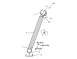
- FIG. 6 shows a state in which the first water conveying structure portion 11a is provided on the upper header 1 of the flat tube 3 tilted backward.
- FIG. 7 shows a state in which the first water conveying structure portion 11a is provided in the upper header 1 of the forward-inclined flat tube 3 in the second heat exchanger 154 according to the second embodiment.
- the first water conveying structure 11a is designed to prevent dewdrops from the upper header 1 due to gravity. It covers part of the bottom of the top header 1 .
- the first water guiding structure portion 11a may come into contact with the corrugated fins 4.
- the first water guiding structure portion 11a contacts the uppermost corrugated fin 4.
- the first water conveying structure portion 11a covers the lower side of the inclined upper header 1 . Therefore, it is possible to prevent the condensed water generated on the surface of the upper header 1 from dropping into the air passages of the corrugated fins 4 .
- FIG. 8 is a schematic side cross-sectional view showing a cross section of the second heat exchanger 154 according to Embodiment 3 as seen from the side.
- FIG. 9 is a diagram showing the first water conveying structure portion 11a of the second heat exchanger 154 according to the third embodiment. As shown in FIG. 9, the water guiding structure 12 has an L-shaped side surface and a comb-shaped lower end. A flat tube 3 is inserted and fixed between the comb-shaped comb teeth, and the lower end is in contact with the corrugated fins 4 .
- the first water guiding structure portion 11a When the center C of the upper header 1 is viewed from the second direction, the first water guiding structure portion 11a has an upper part over the entire range of angles formed by the first direction and a third direction perpendicular to the first and second directions.
- the end located on the heat transfer tube side is on a virtual line extending to the plus side of the first direction, or the virtual line and the third It is located in the area between the imaginary line extending on the negative side of the direction.
- the comb shape of the first water guiding structure 11a is such that the contact position between the first water guiding structure 11a and the corrugated fins 4 is on the windward side of the center of the upper header 1 with respect to the wind direction.
- FIG. 10 is a diagram showing the first water conveying structure portion 11a of the second heat exchanger 154 according to the modification of the third embodiment. As shown in FIG. 10, the first water conveying structure 11a is arranged across the heat exchangers 21a and 21b.
- the first water conveying structure 11a is provided on the upper header 1 of the heat exchanger 21a.
- the first water guiding structure portion 11a has an angle formed by a first direction and a third direction orthogonal to the first direction and the second direction when the center C of the upper header 1 of the heat exchanger 21a is viewed from the second direction. It covers part of the inclined side of the flat tube 3 of the upper header 1 within the range.
- the first water guiding structure portion 11 a guides the condensed water generated on the surface of the upper header 1 of the heat exchanger 21 a to the corrugated fins 4 .
- the first water guiding structure portion 11a is defined by a first direction and a third direction orthogonal to the first direction and the second direction when the center C of the upper header 1 of the heat exchanger 21b is viewed from the second direction.
- the flat tubes 3 of the upper header 1 cover part of the inclined side within the corners.
- the first water guiding structure 11 a guides the condensed water generated on the surface of the upper header 1 of the heat exchanger 21 b to the corrugated fins 4 .
- the condensed water generated in the upper header 1 can be more reliably conveyed to the surfaces of the corrugated fins 4. can be done.
- the side surface of the first water guiding structure portion 11a is L-shaped, the air passage passing between the upper header 1 and the corrugated fins 4 can be blocked. As a result, it is possible to suppress the formation of frost in the air passage caused by bypassing of the corrugated fins 4 by the humid air.
- the heat exchanger 21a and the heat exchanger 21b share one first water conveying structure portion 11a. Therefore, the number of manufactured first water conveying structure portions 11a is reduced, and the manufacturing cost can be reduced.
- Embodiment 4 the surfaces of the first water-conducting structure portion 11a and the second water-conducting structure portion 11b in Embodiment 1 are water-repellent surfaces. In Embodiment 4, the surfaces of the first water-conducting structure portion 11a and the second water-conducting structure portion 11b in Embodiments 2 and 3 are water-repellent surfaces. In Embodiment 4, the surfaces of the corrugated fins 4 in Embodiments 1, 2 and 3 are made hydrophilic.
- FIG. 11 is a diagram for explaining the contact angle ⁇ . As shown in FIG. 11, the contact angle ⁇ is the angle between the solid surface rSL and the droplet surface rLV.
- the water-repellent surface has a contact angle ⁇ of 90° or more.
- the hydrophilic surface has a contact angle ⁇ of 40° or less, ideally 10° or less.
- the droplet has a wettability gradient that changes the contact angle ⁇ , a driving force is generated and it has the property of moving from the water-repellent surface to the hydrophilic surface. Therefore, according to the fourth embodiment, the condensed water is easily guided from the first water conveying structure portion 11a or the second water conveying structure portion 11b toward the corrugated fins 4.
- FIG. 12 is a view showing the first water conveying structure portion 11a provided in the first row heat exchanger 22a and the second row heat exchanger 22b arranged in the third direction of the second heat exchanger 154 according to the fifth embodiment.
- . 13 is a schematic top cross-sectional view showing the AA' cross section of FIG. 12.
- FIG. 13 for the sake of explanation, the position where the first water conveying structure 11a is arranged is indicated by oblique lines.
- the same parts as in FIGS. 2 and 3 are given the same reference numerals, and different parts will be explained here.
- FIG. 12 shows one inclined first row heat exchanger 22a and a second row heat exchanger 22b arranged in parallel in the third direction of the first row heat exchanger 22a.
- FIG. 13 shows the second heat exchanger 154 with two rows and two columns.
- inter-row water conduction holes 31 are provided between the flat tubes 3 of the first row heat exchanger 22a and the flat tubes 3 of the second row heat exchanger 22b.
- the flat tubes 3 of the first row heat exchanger 22a are also called first row heat transfer tubes
- the flat tubes 3 of the second row heat exchanger 22b are also called second row heat transfer tubes.
- the first water guiding structure portion 11 a extends toward the inter-row water guiding holes 31 .
- the corrugated fins 4 are integrally provided between the flat tubes 3 of the first row heat exchanger 22a and the flat tubes 3 of the second row heat exchanger 22b.
- the corrugated fins 4 may be separately provided on the flat tubes 3 of the first row heat exchanger 22a and the flat tubes 3 of the second row heat exchanger 22b.
- the inter-row water guide holes 31 may be provided in the corrugated fins 4 .
- the first water conveying structure portion 11a is provided so as to extend toward the inter-row water conveying holes 31 . Therefore, according to the second heat exchanger 154 according to the fifth embodiment, the condensed water can be discharged more efficiently than through the drainage channels on the corrugated fins 4 .
- FIG. 14 is a schematic side cross-sectional view showing a cross section of the second heat exchanger 154 according to Embodiment 6 as seen from the side.
- the same parts as in FIGS. 2 and 3 are given the same reference numerals, and different parts will be explained here.
- a thermally insulating portion 41 is provided between the first water conveying structure portion 11a and the upper header 1 of the second heat exchanger 154 according to the sixth embodiment.
- a heat insulating portion 41 is provided between the second water conveying structure portion 11 b and the upper header 1 .
- the heat insulation processing part 41 is, for example, one or both of a heat insulation sheet and a hollow structure.
- the heat insulating treatment portion 41 is provided, so that the upper header 1 It is possible to further suppress the air from being cooled and condensed on the surface of the .
Landscapes
- Engineering & Computer Science (AREA)
- Physics & Mathematics (AREA)
- Thermal Sciences (AREA)
- Mechanical Engineering (AREA)
- General Engineering & Computer Science (AREA)
- Heat-Exchange Devices With Radiators And Conduit Assemblies (AREA)
Abstract
La présente invention concerne un échangeur de chaleur comprenant : une pluralité de tubes de transfert de chaleur qui s'étendent chacun dans une première direction et qui sont agencés dans une deuxième direction perpendiculaire à la première direction; un collecteur supérieur qui est disposé sur les extrémités supérieures des tubes de transfert de chaleur et qui s'étend dans la deuxième direction; et une structure de transport d'eau qui recouvre une partie du collecteur supérieur dans la plage d'un angle formé par la première direction et une troisième direction perpendiculaire à la première direction et à la deuxième direction lorsque le centre du collecteur supérieur est vu depuis la deuxième direction et qui guide l'eau condensée générée sur une surface du collecteur supérieur dans les espaces parmi la pluralité de tubes de transfert de chaleur.
Priority Applications (1)
| Application Number | Priority Date | Filing Date | Title |
|---|---|---|---|
| PCT/JP2022/003484 WO2023145042A1 (fr) | 2022-01-31 | 2022-01-31 | Échangeur de chaleur |
Applications Claiming Priority (1)
| Application Number | Priority Date | Filing Date | Title |
|---|---|---|---|
| PCT/JP2022/003484 WO2023145042A1 (fr) | 2022-01-31 | 2022-01-31 | Échangeur de chaleur |
Publications (1)
| Publication Number | Publication Date |
|---|---|
| WO2023145042A1 true WO2023145042A1 (fr) | 2023-08-03 |
Family
ID=87470916
Family Applications (1)
| Application Number | Title | Priority Date | Filing Date |
|---|---|---|---|
| PCT/JP2022/003484 WO2023145042A1 (fr) | 2022-01-31 | 2022-01-31 | Échangeur de chaleur |
Country Status (1)
| Country | Link |
|---|---|
| WO (1) | WO2023145042A1 (fr) |
Citations (9)
| Publication number | Priority date | Publication date | Assignee | Title |
|---|---|---|---|---|
| JPH0612425Y2 (ja) * | 1990-01-18 | 1994-03-30 | ピーエス工業株式会社 | 冷房用熱交換器 |
| JPH07172152A (ja) * | 1993-05-19 | 1995-07-11 | Nippondenso Co Ltd | 空気調和装置のクーリングユニットおよび排水ケース |
| JP2002213840A (ja) * | 2001-01-19 | 2002-07-31 | Denso Corp | 蒸発器 |
| JP2004316976A (ja) * | 2003-04-14 | 2004-11-11 | Japan Climate Systems Corp | 熱交換器 |
| KR20100097344A (ko) * | 2009-02-26 | 2010-09-03 | 한라공조주식회사 | 배수성 향상된 자동차용 공조장치 |
| JP2015222146A (ja) * | 2014-05-23 | 2015-12-10 | パナソニックIpマネジメント株式会社 | 熱交換器 |
| JP2015224844A (ja) * | 2014-05-29 | 2015-12-14 | パナソニックIpマネジメント株式会社 | 熱交換器 |
| JP2015227754A (ja) * | 2014-06-02 | 2015-12-17 | パナソニックIpマネジメント株式会社 | 熱交換器 |
| JP2016020759A (ja) * | 2014-07-14 | 2016-02-04 | カルソニックカンセイ株式会社 | 熱交換器 |
-
2022
- 2022-01-31 WO PCT/JP2022/003484 patent/WO2023145042A1/fr unknown
Patent Citations (9)
| Publication number | Priority date | Publication date | Assignee | Title |
|---|---|---|---|---|
| JPH0612425Y2 (ja) * | 1990-01-18 | 1994-03-30 | ピーエス工業株式会社 | 冷房用熱交換器 |
| JPH07172152A (ja) * | 1993-05-19 | 1995-07-11 | Nippondenso Co Ltd | 空気調和装置のクーリングユニットおよび排水ケース |
| JP2002213840A (ja) * | 2001-01-19 | 2002-07-31 | Denso Corp | 蒸発器 |
| JP2004316976A (ja) * | 2003-04-14 | 2004-11-11 | Japan Climate Systems Corp | 熱交換器 |
| KR20100097344A (ko) * | 2009-02-26 | 2010-09-03 | 한라공조주식회사 | 배수성 향상된 자동차용 공조장치 |
| JP2015222146A (ja) * | 2014-05-23 | 2015-12-10 | パナソニックIpマネジメント株式会社 | 熱交換器 |
| JP2015224844A (ja) * | 2014-05-29 | 2015-12-14 | パナソニックIpマネジメント株式会社 | 熱交換器 |
| JP2015227754A (ja) * | 2014-06-02 | 2015-12-17 | パナソニックIpマネジメント株式会社 | 熱交換器 |
| JP2016020759A (ja) * | 2014-07-14 | 2016-02-04 | カルソニックカンセイ株式会社 | 熱交換器 |
Similar Documents
| Publication | Publication Date | Title |
|---|---|---|
| CN107429975B (zh) | 热交换器及空调机 | |
| WO2019239446A1 (fr) | Unité extérieure de climatiseur et climatiseur associé | |
| US20100006276A1 (en) | Multichannel Heat Exchanger | |
| US20110030932A1 (en) | Multichannel heat exchanger fins | |
| WO2013160957A1 (fr) | Échangeur de chaleur, unité intérieure, et dispositif de cycle de réfrigération | |
| JP2010060274A (ja) | 相違する流れを有するマルチチャネル熱交換器 | |
| EP3156752B1 (fr) | Échangeur thermique | |
| JP6590948B2 (ja) | 熱交換器および冷凍サイクル装置 | |
| CN107407512B (zh) | 热交换器及空调机 | |
| US11175053B2 (en) | Heat exchanger, refrigeration cycle device, and air-conditioning apparatus | |
| JPWO2018078800A1 (ja) | 熱交換器及び冷凍サイクル装置 | |
| JP6727297B2 (ja) | 室外ユニットおよびそれを備えた冷凍サイクル装置 | |
| JP2009150621A (ja) | 熱交換器及び空気調和機 | |
| WO2016121119A1 (fr) | Échangeur de chaleur et dispositif à cycle de réfrigération | |
| WO2023145042A1 (fr) | Échangeur de chaleur | |
| CN111512099B (zh) | 热交换器及制冷循环装置 | |
| JP2006177573A (ja) | 空気調和機 | |
| JP2008075998A (ja) | 空気調和装置 | |
| TWI731588B (zh) | 空調機 | |
| CN111902683B (zh) | 热交换器及制冷循环装置 | |
| WO2020121517A1 (fr) | Unité intérieure, et conditionneur d'air | |
| WO2022249281A1 (fr) | Échangeur de chaleur et climatiseur | |
| WO2011111602A1 (fr) | Climatiseur | |
| JP7150157B2 (ja) | 熱交換器および冷凍サイクル装置 | |
| JPWO2019176061A1 (ja) | 熱交換器及び冷凍サイクル装置 |
Legal Events
| Date | Code | Title | Description |
|---|---|---|---|
| 121 | Ep: the epo has been informed by wipo that ep was designated in this application |
Ref document number: 22923906 Country of ref document: EP Kind code of ref document: A1 |
|
| ENP | Entry into the national phase |
Ref document number: 2023576556 Country of ref document: JP Kind code of ref document: A |