WO2023144985A1 - Système de commande d'ascenseur - Google Patents
Système de commande d'ascenseur Download PDFInfo
- Publication number
- WO2023144985A1 WO2023144985A1 PCT/JP2022/003244 JP2022003244W WO2023144985A1 WO 2023144985 A1 WO2023144985 A1 WO 2023144985A1 JP 2022003244 W JP2022003244 W JP 2022003244W WO 2023144985 A1 WO2023144985 A1 WO 2023144985A1
- Authority
- WO
- WIPO (PCT)
- Prior art keywords
- car
- control system
- hoistway
- reference position
- detection
- Prior art date
Links
Images

Classifications
-
- B—PERFORMING OPERATIONS; TRANSPORTING
- B66—HOISTING; LIFTING; HAULING
- B66B—ELEVATORS; ESCALATORS OR MOVING WALKWAYS
- B66B3/00—Applications of devices for indicating or signalling operating conditions of elevators
- B66B3/02—Position or depth indicators
Definitions
- This disclosure relates to an elevator control system.
- Patent Document 1 discloses an example of an elevator.
- An elevator magnetic tape is placed in the hoistway.
- the car position detection device detects the position of the car in the hoistway by reading data on the magnetic tape with a magnetic sensor.
- calibrating the car position detector the car is manually moved to the top and bottom floors and the position data of the top and bottom floors are read. Based on the error between the read data and the preset designed positions of the lowest floor and the highest floor, the preset positions of each floor are corrected.
- the length of the detection tape used to detect the position of the car may change over time due to, for example, expansion and contraction due to temperature changes in the hoistway.
- the elevator of Patent Literature 1 there is a possibility that the positions of the cars corresponding to each floor that are adjusted by manual operation will largely deviate due to changes over time.
- the present disclosure relates to solving such problems.
- the present disclosure provides an elevator control system capable of suppressing the effects of car misalignment even when the length of the detection tape changes over time.
- An elevator control system is provided with information representing a longitudinal position in the longitudinal direction, is arranged so that the longitudinal direction is the vertical direction in a hoistway over a plurality of floors of a building, and is arranged at one end in the vertical direction.
- a detection tape having a portion fixedly installed with respect to the hoistway as a fixed end and the other end in the vertical direction as a movable end installed movably in the vertical direction with respect to the hoistway;
- a reading device installed in a car traveling in a direction and reading information indicating a longitudinal position attached to the detection tape, a detector for detecting a detected object and the detected object, the detected object and One of the detectors is installed in the car, the other of the object to be detected and the detector is installed at a preset reference position on the movable end side in the vertical direction of the hoistway, and the detector is installed in the car.
- a detection device for detecting that the car is at the reference position by detecting an object to be detected; and correcting the absolute position of the car using the longitudinal position read by the reading device when the detecting device detects that the car is at the reference position; Prepare.
- FIG. 1 is a configuration diagram of an elevator according to Embodiment 1;
- FIG. 4 is a flow chart showing an example of the operation of the control system according to Embodiment 1;
- 2 is a hardware configuration diagram of main parts of the control system according to Embodiment 1.
- FIG. 1 is a configuration diagram of an elevator according to Embodiment 1;
- FIG. 4 is a flow chart showing an example of the operation of the control system according to Embodiment 1;
- 2 is a hardware configuration diagram of main parts of the control system according to Embodiment 1.
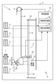
- FIG. 1 is a configuration diagram of an elevator 1 according to Embodiment 1. As shown in FIG. 1
- the elevator 1 is applied, for example, to a building 2 having multiple floors.
- a hoistway 3 for an elevator 1 is provided in a building 2 .
- the hoistway 3 is a vertically elongated space extending over a plurality of floors.
- a landing 4 for an elevator 1 is provided on each floor of the building 2 .
- a landing 4 is a place adjacent to the hoistway 3 .
- the elevator 1 comprises a hoisting machine 5 , a main rope 6 , a car 7 and a control system 8 .
- the hoist 5 includes a motor and a sheave.
- the hoist 5 is provided, for example, above or below the hoistway 3 .
- the hoist 5 may be arranged in the machine room.
- the motor of the hoist 5 is a device that generates driving force.
- the sheave of the hoisting machine 5 is connected to the rotating shaft of the motor of the hoisting machine 5 .
- the sheave of the hoisting machine 5 is rotated by the driving force generated by the motor of the hoisting machine 5 .
- the main rope 6 is wound around the sheave of the hoisting machine 5.
- the main rope 6 moves so as to be hoisted or paid out by the rotation of the sheave of the hoisting machine 5 .
- the main rope 6 supports the load of the car 7 on one side of the sheave of the hoist 5 .
- the car 7 is arranged in the hoistway 3.
- the car 7 travels vertically in the hoistway 3 as the hoisting machine 5 moves the main rope 6 .
- the car 7 is a device for transporting passengers on board between a plurality of floors by traveling up and down the hoistway 3 .
- a stop position is set at each floor.
- the stop position of the floor of the building 2 is the vertical position on the building 2 at which the car 7 is stopped on the floor.
- the control system 8 includes a detection tape 9 , a reader 10 , a detection device 11 , a temperature sensor 12 and a control device 13 .
- the detection tape 9 is a tape-shaped device that is long in one direction.
- Information representing the longitudinal position on the detection tape 9 is attached along the length of the detection tape 9 .
- Information representing the position in the longitudinal direction is attached to the detection tape 9 as magnetic data, for example, when the detection tape 9 is a magnetic tape.
- the information representing the longitudinal position may be provided on the surface of the detection tape 9 as, for example, a coded image containing a two-dimensional code.
- the detection tape 9 is arranged on the hoistway 3 so that its longitudinal direction is oriented vertically. One vertical end of the detection tape 9 is fixed to the hoistway 3 as a fixed end 14 .
- the other vertical end of the detection tape 9 is installed as a movable end 15 so as to be vertically movable with respect to the hoistway 3 .
- the upper end of the detection tape 9 is installed as the fixed end 14 .
- fixed end 14 is attached directly to the structure of building 2 .
- the structure of the building 2 includes, for example, inner walls of the hoistway 3, columns, or beams.
- the lower end of the detection tape 9 is installed as the movable end 15 .
- the movable end 15 is mounted via a spring so that the detection tape 9 can be tensioned, for example.
- the movable end 15 may be supported by a slide bearing or the like so as to be vertically slidable.
- the reading device 10 is a device that reads information representing the longitudinal position attached to the detection tape 9 .
- a reader 10 is installed in the car 7 .
- the reader 10 moves vertically in the hoistway 3 together with the car 7 .
- the reader 10 reads longitudinal position information from the detection tape 9 by, for example, a magnetic sensor, camera, or other device.
- the reading device 10 is connected to the control device 13 so as to output reading results.
- a reference position is set in advance in the control system 8 .
- the reference position is set on the side of the movable end 15 in the vertical direction of the hoistway 3 .
- the reference position is a vertical position on the building 2 .
- the lower end of the detection tape 9 is installed as the movable end 15 , so the reference position is set below the hoistway 3 .
- the reference position is set below the intermediate portion of the hoistway 3, for example.
- the reference position is set, for example, in the vicinity of the frequently stopped floor.
- the frequent stop floor is a floor set in advance as a floor on which the car 7 stops more frequently than other floors. Frequent stopping floors are, for example, floors where the car 7 stops more frequently than the average stop frequency of each floor of the building 2 .
- Frequent stop floors may be the standard floor of building 2, the entrance floor, the lobby floor, or the ground floor.
- a frequent stop floor may be, for example, a floor where a front desk or the like is located.
- the vicinity of the frequently-stopping floor is, for example, the range from the stop position of the car 7 at the frequently-stopping floor to the stop position of the car 7 at a floor adjacent to the frequently-stopping floor.
- the range may include stop positions of frequent stop floors.
- the reference position may be set to the stop position of the frequently stopped floor.
- the detection device 11 includes an object to be detected and a detector.
- a detector is a device that detects an object to be detected. One of the object to be detected and the detector is installed in the car 7 . The other of the object to be detected and the detector is installed at a reference position in the hoistway 3 . Of the object to be detected and the detector, the one installed in the car 7 moves vertically in the hoistway 3 as the car 7 travels.
- the detection device 11 detects that the car 7 is at the reference position by detecting the object to be detected by the detector.
- the detector is connected to the control device 13 so as to be able to output detection results.
- the sensing device 11 includes a sensed cam 16 and a sensing switch 17 .
- the detectable cam 16 is an example of a detectable body.
- the detected cam 16 is installed on the car 7 .
- the detection switch 17 detects the detected cam 16 by contact when the car 7 passes the reference position.
- the detection switch 17 is an example of a detector.
- the detection switch 17 is installed at the reference position.
- the sensing switch 17 is attached directly to the structure of the building 2 .
- the detection device 11 may include a detector that detects an object to be detected in a non-contact manner.
- the sensing device 11 may include, for example, an iron plate and a magnetic sensor, a light reflecting plate and a photoelectric sensor, or a marker and a camera as the object to be sensed and the detector.
- the detected object may be installed at the reference position. At this time, the object to be detected is directly attached to the structure of the building 2, for example.
- a detector is also installed in the car 7 .
- the control system 8 includes only one set of sensed object and detector of the sensing device 11 .
- the temperature sensor 12 is arranged in the hoistway 3.
- a temperature sensor 12 measures the temperature inside the hoistway 3 .
- the temperature sensor 12 is connected to the controller 13 so as to output the measurement results.
- the control device 13 is, for example, the control panel of the elevator 1.
- the control device 13 is provided, for example, above or below the hoistway 3 .
- the control device 13 may be arranged in the machine room.
- the control device 13 is connected to the hoisting machine 5 so as to be able to communicate control signals and the like.
- the control device 13 includes a control processor 18 and a correction processor 19 .
- the control processing unit 18 is a part that has a function to perform control processing of the elevator 1.
- the control processing includes operation control of the elevator 1, safety monitoring, and the like.
- the operation control of the elevator 1 includes, for example, running and stopping control of the car 7 .
- Safety monitoring of the elevator 1 includes, for example, terminal speed monitoring including a terminal floor forced reduction device, final limit switch, or monitoring of safety devices such as a door open protection device, and operation control of the elevator 1 based on the results thereof.
- the absolute position of car 7 is detected based on the longitudinal position on detection tape 9 read from detection tape 9 by reader 10 . That is, the control processing unit 18 performs the control processing of the elevator 1 using the longitudinal position read from the detection tape 9 as the absolute position of the car 7 in the vertical direction of the hoistway 3 .
- the correction processing unit 19 is a part equipped with a function for correcting the absolute position of the car 7.
- the correction processing unit 19 corrects the absolute position of the car 7, for example, when the detection device 11 detects that the car 7 is at the reference position.
- the correction processing unit 19 calculates the correction coefficient C by, for example, the following formula (1).
- y 0 represents the longitudinal position of the fixed end 14 of the detection tape 9 .
- y * represents the longitudinal position of the detection tape 9 read by the reader 10 when the detector 11 detects that the car 7 is at the reference position. That is, y 0 ⁇ y * is the detection from the fixed end 14 up to the position where the reading device 10 reads the information representing the longitudinal position when the detection device 11 detects that the car 7 is at the reference position. It represents the length on the tape 9.
- x 0 represents the installation position on the building 2 of the fixed end 14 of the detection tape 9 .
- x * represents a reference position. That is, x 0 -x * represents the length on the building 2 from the installation position of the fixed end 14 to the reference position.
- a correction coefficient C is calculated as a ratio of these lengths.
- the position y 0 of the fixed end 14 of the detection tape 9 on the detection tape 9 and the installation position x 0 of the fixed end 14 of the detection tape 9 on the building 2 are set in advance in the control system 8, for example, based on design values. It is
- the correction processing unit 19 corrects the absolute position x of the car 7 from the longitudinal position y on the detection tape 9 using the following equation (2).
- x(n) represents the stop position of the n-th floor of building 2, where n is a natural number equal to or less than the number of floors of building 2.
- the nth floor of building 2 may be a frequent stop floor, or some other floor.
- the stop position x(n) of each floor is set in advance in the control system 8 by, for example, a design value or adjustment or learning at the initial stage of installation.
- the control processing unit 18 controls the corrected absolute position x of the car 7 with the stop position x(n) of the n-th floor as the target position, thereby moving the car 7 to the stop position of the floor. stop.
- the correction processing unit 19 may perform correction without using a method of accurately proportional to the length on the building 2 or the length on the detection tape 9 or the like.
- the correction processing unit 19 may perform stepwise correction according to, for example, the length on the building 2 or the length on the detection tape 9 .
- the correction processing section 19 may perform correction according to the distribution characteristics.
- the distribution characteristic of the detection tape 9 is, for example, a characteristic representing the longitudinal distribution of the material, physical property value, size, shape, tension, or the like of the detection tape 9 .
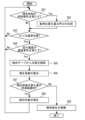
- FIG. 2 is a flow chart showing an example of the operation of the control system 8 according to the first embodiment.
- step S01 the correction processing unit 19 determines whether the current time satisfies preset time conditions.
- the time condition for the current time is, for example, a condition such as when the current time matches a preset correction time.
- the correction time may be a time set periodically.
- the time condition for the current time may be, for example, a condition such as when a preset time interval has elapsed since the time when the correction processing unit 19 performed the previous correction. If the current time satisfies the time condition, the process of control system 8 proceeds to step S02. If the current time does not satisfy the time condition, the process of control system 8 proceeds to step S03.
- the control processing unit 18 generates a call for the car 7 to pass through the reference position.
- the call generated by the control processing unit 18 is, for example, in the direction from the frequent stop floor to the adjacent floor when the reference position is in the range from the stop position of the frequent stop floor to the stop position of the adjacent floor. It is a call to run.
- the call generated by the control processing unit 18 is, for example, a call to drive the car 7 to the frequent stop floor or a call to make the car 7 pass the frequent stop floor. is.
- the control processing unit 18 causes the car 7 to travel in the hoistway 3 so as to respond to calls generated by the control processing unit 18 and calls registered by users. After that, the processing of the control system 8 proceeds to step S03.
- the control processing unit 18 controls the movement of the car 7 so that the car 7 passes the reference position at a lower speed than the running speed during normal operation when the car 7 responds to the call generated by the control processing unit 18. You can slow down and run. At this time, the control processing unit 18 may cause the car 7 to respond to the call after confirming that the user is not in the car 7 . Whether the user is not in the car 7 is confirmed, for example, based on the load measured by a weighing device (not shown) provided in the car 7 .
- step S03 the correction processing unit 19 determines whether the detection device 11 has detected that the car 7 is at the reference position.
- the car 7 may be running in response to a call registered by the user.
- the car 7 may run in response to a call generated by the control processor 18 .
- the car 7 may run without answering the call to move to a waiting position or the like. If the detection device 11 does not detect that the car 7 is at the reference position, the processing of the control system 8 proceeds to step S01. When the detection device 11 detects that the car 7 is at the reference position, the processing of the control system 8 proceeds to step S04.
- step S04 the correction processing unit 19 determines whether the travel speed of the car 7 when the detection device 11 detects that the car 7 is at the reference position satisfies a preset speed condition.
- the speed condition for the running speed of the car 7 is, for example, a condition such as when the running speed is lower than a preset speed threshold.
- the speed threshold is set, for example, as a speed capable of suppressing an error in reading the absolute position of the car 7 due to the influence of detection delay in the detection device 11 to an allowable error or less required for the control system 8 as a whole.
- the speed threshold is set, for example, to a speed lower than the rated traveling speed between floors during normal operation of the car 7 .
- the speed threshold may be a speed after deceleration when the car 7 is decelerated when it stops at the frequent stop floor.
- the speed condition is met when the car 7 stops at the frequent stop floor.
- step S05 the reading device 10 reads the longitudinal position y * on the detection tape 9.
- FIG. The correction processing unit 19 stores the longitudinal position y * on the detection tape 9 read by the reading device 10 . After that, the processing of the control system 8 proceeds to step S06.
- step S06 the correction processing unit 19 calculates the correction coefficient C using, for example, formula (1). After that, the processing of the control system 8 proceeds to step S07.
- step S07 the correction processing unit 19 calculates the amount of change in the current absolute position of the car 7 before and after the correction coefficient C is calculated.
- the amount of change before and after the calculation of the correction coefficient C may be calculated.
- the correction processing unit 19 calculates the absolute position x of the car 7 according to the equation (2) before the correction coefficient C is newly calculated in step S06 and the equation (2 ) from the absolute position x of the car 7 is calculated as the amount of change.
- the correction processing unit 19 may calculate the amount of change for the absolute position of the car 7 corresponding to the stop position of another floor.
- the correction processing section 19 may calculate the amount of change for the absolute position of the car 7 corresponding to the reference position.
- the correction processing unit 19 determines whether the calculated amount of change is within a preset allowable range.
- the correction processing unit 19 may calculate the amount of change for each function of the control processing unit 18 that requires the absolute position of the car 7 .
- the allowable range of variation may be set for each function of the control processing section 18 that requires the absolute position of the car 7 .
- the amount of variation or tolerance for the lift stroke may be used in the determination.
- the amount of change or allowable range for the floor closest to the movable end 15 of the detection tape 9 may be used for determination. If the amount of change is within the allowable range, the process of control system 8 proceeds to step S08. If the amount of change is not within the allowable range, the process of control system 8 proceeds to step S09.
- step S08 the correction processing unit 19 corrects the absolute position of the car 7 by, for example, updating the correction coefficient C used in formula (2). After that, the processing of the control system 8 proceeds to step S01.
- step S09 the control processing unit 18 determines that an abnormality has occurred in the control system 8.
- the control processing unit 18 determines, for example, that an abnormality has occurred in the detection tape 9 .
- the control processing unit 18 may issue a notification of the abnormality that has occurred.
- the notification is sent, for example, to an information center (not shown) that collects information on the elevator 1 through a communication network such as the Internet.
- the notification may be sent to, for example, a mobile terminal possessed by the manager of the elevator 1 through a communication network such as the Internet.
- the processing of the control system 8 then ends.
- the control system 8 includes the detection tape 9, the reading device 10, the detection device 11, and the control device 13.
- the detection tape 9 is arranged in the hoistway 3 extending over a plurality of floors of the building 2 so that the longitudinal direction thereof is the vertical direction.
- One vertical end of the detection tape 9 is fixed to the hoistway 3 as a fixed end 14 .
- the other end of the detection tape 9 in the vertical direction is installed as a movable end 15 so as to be movable in the vertical direction with respect to the hoistway 3 .
- the reader 10 is installed in a car 7 that runs vertically in the hoistway 3 .
- the reading device 10 reads the information representing the longitudinal position attached to the detection tape 9 .
- the detection device 11 includes a detected cam 16 and a detection switch 17 for detecting the detected cam 16 .
- a detection switch 17 is installed on the car 7 .
- the detected cam 16 is installed at the reference position.
- the reference position is a position preset on the side of the movable end 15 in the vertical direction of the hoistway 3 .
- the detection device 11 detects that the car 7 is at the reference position by detecting the detected cam 16 with the detection switch 17 .
- the control device 13 performs control processing of the car 7 using the longitudinal position read by the reading device 10 as the absolute position of the car 7 in the vertical direction in the hoistway 3 .
- the controller 13 corrects the absolute position of the car 7 using the longitudinal position read by the reader 10 when the detector 11 detects that the car 7 is at the reference position.
- the control system 8 can correct the absolute position of the car 7 each time the car 7 passes the reference position. , the influence of the positional deviation of the car 7 is suppressed.
- the length of the detection tape 9 can change over time, for example, due to expansion and contraction associated with temperature changes in the hoistway 3 .
- the elevator 1 is a see-through elevator for viewing, and the hoistway 3 is made of glass and has a high lift, the temperature change in the hoistway 3 can be large. In such an elevator 1, there is a possibility that the temperature change will be large for about one hour, and the expansion and contraction of the detection tape 9 may become 5 mm or more in about one hour. In such a case, the influence of expansion and contraction of the detection tape 9 cannot be ignored.
- the absolute position of the car 7 based on the information read from the detection tape 9 can be corrected when the car 7 passes the reference position. can be reduced by correction. As a result, the landing position of the car 7 is less likely to shift, and the user can use the elevator 1 more comfortably. Further, the object to be detected or the detector of the detection device 11 does not have to be arranged for each floor of the building 2 . Since one set of the object to be detected and the detector of the detection device 11 is sufficient, even in the elevator 1 having a high lift and a large number of floors, the equipment installation cost and maintenance cost can be reduced.
- the reference position is set in the range from the stop position of the frequent stop floor to the stop position of the adjacent floor.
- the range includes stop positions of frequent stop floors. Frequent stopping floors are preset as floors that the car 7 stops at more frequently than other floors.
- the control system 8 gets frequent opportunities to correct the absolute position of the car 7 .
- the control system 8 gets frequent opportunities to correct the absolute position of the car 7 .
- control device 13 generates a call for the car 7 to pass through the reference position when the current time satisfies a preset time condition.
- the control system 8 can control the absolute position of the car 7 at a preset timing. An opportunity for position correction becomes available. As a result, it is possible to suppress the elapse of a long period of time without correcting the absolute position. Therefore, even if the length of the detection tape 9 changes over time, the influence of the shift in the position of the car 7 can be effectively reduced. suppressed.
- control system 8 may include a temperature sensor 12.
- a temperature sensor 12 is installed in the hoistway 3 .
- the control processing unit 18 of the control device 13 may generate a call for the car 7 to pass through the reference position when the temperature measured by the temperature sensor 12 satisfies a preset temperature condition.
- the temperature condition for the temperature of the hoistway 3 measured by the temperature sensor 12 is, for example, when the temperature of the hoistway 3 exceeds a preset temperature threshold, or when the temperature of the hoistway 3 exceeds a preset temperature range. It is a condition such as when entering
- control system 8 will have the opportunity to correct the absolute position of the car 7 as needed due to temperature changes in the hoistway 3 . This prevents the absolute position from being corrected even if the temperature of the hoistway 3 changes. The influence of misalignment is suppressed more effectively.
- the control system 8 may generate a call based on both the time condition and the temperature condition. Control system 8 may generate a call based on only one of the time of day and temperature conditions. Alternatively, control system 8 may not generate calls based on time of day or temperature conditions.
- control device 13 determines the absolute position of the car 7 corresponding to the stop position of each floor on the condition that the speed of the car 7 when passing the reference position is lower than a preset speed threshold. is corrected. At this time, the control device 13 uses the longitudinal position read by the reading device 10 when the detection device 11 detects that the car 7 is at the reference position when the condition is satisfied.
- the reading of the absolute position of the car 7 used for correction is less susceptible to the detection delay in the detection device 11 . Therefore, the information used for correction can be obtained with higher accuracy, so that the accuracy of correction can be further improved.
- the control device 13 may correct the absolute position each time the car 7 passes the reference position regardless of the running speed of the car 7 .
- control device 13 determines the length from the fixed end 14 to the position where the reading device 10 reads the information representing the position in the longitudinal direction when the detection device 11 detects that the car 7 is at the reference position, and A ratio of the length from the installation position of the fixed end 14 to the reference position is calculated as a correction coefficient.
- the control device 13 corrects the absolute position of the car 7 using a value obtained by multiplying the length based on the fixed end 14 by the calculated correction coefficient.
- the control device 13 also determines whether the amount of change before and after the correction of the absolute position of the car 7 corresponding to at least one of the stop position and the reference position of each floor is within a preset allowable range. The control device 13 corrects the absolute position of the car 7 when the amount of change is within the allowable range.
- the correction processing unit 19 of the control device 13 may calculate the error of the absolute position of the car 7 corresponding to the stop position of any floor of the building 2 after calculating the correction coefficient.
- the correction processing unit 19 calculates, as an error, the difference between, for example, the stop position of the frequently stopped floor and the absolute position of the car 7 corresponding to the stop position.
- the correction processing unit 19 may calculate the error of the absolute position of the car 7 corresponding to the stop position of another floor.
- the correction processing section 19 may calculate the error of the absolute position of the car 7 corresponding to the reference position.
- the correction processing unit 19 determines whether the calculated error is within a preset allowable range.
- the permissible ranges set for the error in the absolute position of the car 7 and the amount of change before and after the correction may be different from each other or may be the same. If the error is within the permissible range, the controller 13 performs a correction of the absolute position of the car 7. On the other hand, if the error is not within the allowable range, the control device 13 determines that the control system 8 is abnormal.
- the control system 8 can detect an abnormality occurring in the detection tape 9 . It should be noted that the control system 8 may determine abnormality based on both the amount of change in the absolute position of the car 7 and the error. The control system 8 may determine the abnormality based on only one of the amount of change in the absolute position of the car 7 and the error. Alternatively, the control system 8 does not need to determine the abnormality based on the amount of change or error in the absolute position of the car 7 .
- the fixed end 14 of the detection tape 9 is attached to the structure of the building 2 .
- the detected object and the detector whichever is installed at the reference position, are attached to the structure of the building 2 .
- the installation position of the fixed end 14 of the detection tape 9 and the reference position are displaced by the shrinkage of the building 2 itself. become incorporated into As a result, the landing position of the car 7 is less likely to shift, and the user can use the elevator 1 more comfortably.
- the detection tape 9 may be installed on the hoistway 3 with the lower end as the fixed end 14 . At this time, the detection tape 9 is installed on the hoistway 3 with the upper end as the movable end 15 . In this case, the reference position is set above the hoistway 3 . Further, the frequent stop floor may be set to a transfer floor above the hoistway 3, for example.
- the correction processing unit 19 corrects the absolute position of the car 7 using the correction coefficient C for conversion of the position y on the detection tape 9 to the position x on the building 2.
- the correction processing unit 19 may correct the absolute position of the car 7 by updating the target position corresponding to the stop position of each floor using the correction coefficient C' as follows.
- the correction processing unit 19 calculates the correction coefficient C' by, for example, the following formula (3).
- the correction processing unit 19 calculates the longitudinal position y(n) on the detection tape 9 corresponding to the stop position of the n-th floor of the building 2 using the correction coefficient C' according to the following equation (4). Update.
- control processing unit 18 sets, for example, the position y(n) on the detection tape 9 corresponding to the n-th floor as the target position of the longitudinal position y read by the reading device 10 moving together with the car 7. By controlling the position of the car 7, the car is stopped at the stop position of the floor.
- FIG. 3 is a hardware configuration diagram of main parts of the control system 8 according to the first embodiment.
- the processing circuitry comprises at least one processor 100a and at least one memory 100b.
- the processing circuitry may comprise at least one piece of dedicated hardware 200 in conjunction with or in place of processor 100a and memory 100b.
- each function of the control system 8 is realized by software, firmware, or a combination of software and firmware. At least one of software and firmware is written as a program.
- the program is stored in memory 100b.
- the processor 100a realizes each function of the control system 8 by reading and executing the programs stored in the memory 100b.
- the processor 100a is also called a CPU (Central Processing Unit), a processing device, an arithmetic device, a microprocessor, a microcomputer, or a DSP.
- the memory 100b is composed of, for example, nonvolatile or volatile semiconductor memory such as RAM, ROM, flash memory, EPROM, and EEPROM.
- the processing circuit may be implemented, for example, as a single circuit, multiple circuits, a programmed processor, a parallel programmed processor, an ASIC, an FPGA, or a combination thereof.
- Each function of the control system 8 can be implemented by a processing circuit. Alternatively, each function of the control system 8 can be collectively realized by a processing circuit. A part of each function of the control system 8 may be realized by dedicated hardware 200 and the other part may be realized by software or firmware. Thus, the processing circuitry implements each function of control system 8 in dedicated hardware 200, software, firmware, or a combination thereof.
- control system according to the present disclosure can be applied to elevators.
Abstract
L'invention concerne un système de commande d'ascenseur qui peut supprimer les effets d'un déplacement de cabine, même lorsque la longueur d'une bande de détection change au fil du temps. Un système de commande (8) a une bande de détection (9) qui est disposée dans une cage d'ascenseur (3) de façon à avoir une extrémité fixe (14) et une extrémité mobile (15) dans la direction verticale. Un dispositif de lecture (10) qui est disposé sur une cabine (7) lit des informations sur la bande de détection (9) qui indiquent une position dans la direction longitudinale. Un dispositif de détection (11) détecte le fait que la cabine (7) se trouve à une position de référence qui se trouve du côté extrémité mobile (15) de la cage d'ascenseur (3) à la suite d'une détection, par un commutateur de détection (17) qui est disposé à la position de référence, d'une came cible de détection (16) qui est disposée sur la cabine (7). Un dispositif de commande (13) effectue un traitement de commande qui traite la position lue par le dispositif de lecture (10) comme la position absolue de la cabine (7). Le dispositif de commande (13) corrige la position absolue de la cabine (7) à l'aide de la position dans la direction longitudinale lue par le dispositif de lecture (10) au moment de la détection par le dispositif de détection (11).
Priority Applications (1)
| Application Number | Priority Date | Filing Date | Title |
|---|---|---|---|
| PCT/JP2022/003244 WO2023144985A1 (fr) | 2022-01-28 | 2022-01-28 | Système de commande d'ascenseur |
Applications Claiming Priority (1)
| Application Number | Priority Date | Filing Date | Title |
|---|---|---|---|
| PCT/JP2022/003244 WO2023144985A1 (fr) | 2022-01-28 | 2022-01-28 | Système de commande d'ascenseur |
Publications (1)
| Publication Number | Publication Date |
|---|---|
| WO2023144985A1 true WO2023144985A1 (fr) | 2023-08-03 |
Family
ID=87471290
Family Applications (1)
| Application Number | Title | Priority Date | Filing Date |
|---|---|---|---|
| PCT/JP2022/003244 WO2023144985A1 (fr) | 2022-01-28 | 2022-01-28 | Système de commande d'ascenseur |
Country Status (1)
| Country | Link |
|---|---|
| WO (1) | WO2023144985A1 (fr) |
Citations (6)
| Publication number | Priority date | Publication date | Assignee | Title |
|---|---|---|---|---|
| WO2014184869A1 (fr) * | 2013-05-14 | 2014-11-20 | 三菱電機株式会社 | Dispositif d'ascenseur, et son procédé de commande |
| JP2019116337A (ja) * | 2017-12-26 | 2019-07-18 | フジテック株式会社 | ダブルデッキエレベータ |
| JP2019199347A (ja) * | 2018-05-18 | 2019-11-21 | 株式会社日立ビルシステム | かご位置特定装置及びかご位置特定方法 |
| WO2020065788A1 (fr) * | 2018-09-26 | 2020-04-02 | 株式会社日立製作所 | Dispositif de commande d'ascenseur et ascenseur l'utilisant |
| WO2020115900A1 (fr) * | 2018-12-07 | 2020-06-11 | 株式会社日立製作所 | Dispositif d'ascenseur |
| JP2021066567A (ja) * | 2019-10-24 | 2021-04-30 | 株式会社日立ビルシステム | エレベータ装置 |
-
2022
- 2022-01-28 WO PCT/JP2022/003244 patent/WO2023144985A1/fr unknown
Patent Citations (6)
| Publication number | Priority date | Publication date | Assignee | Title |
|---|---|---|---|---|
| WO2014184869A1 (fr) * | 2013-05-14 | 2014-11-20 | 三菱電機株式会社 | Dispositif d'ascenseur, et son procédé de commande |
| JP2019116337A (ja) * | 2017-12-26 | 2019-07-18 | フジテック株式会社 | ダブルデッキエレベータ |
| JP2019199347A (ja) * | 2018-05-18 | 2019-11-21 | 株式会社日立ビルシステム | かご位置特定装置及びかご位置特定方法 |
| WO2020065788A1 (fr) * | 2018-09-26 | 2020-04-02 | 株式会社日立製作所 | Dispositif de commande d'ascenseur et ascenseur l'utilisant |
| WO2020115900A1 (fr) * | 2018-12-07 | 2020-06-11 | 株式会社日立製作所 | Dispositif d'ascenseur |
| JP2021066567A (ja) * | 2019-10-24 | 2021-04-30 | 株式会社日立ビルシステム | エレベータ装置 |
Similar Documents
| Publication | Publication Date | Title |
|---|---|---|
| CN110615331B (zh) | 用于电梯的位置参考装置 | |
| KR100681078B1 (ko) | 엘리베이터 장치 | |
| JP4368854B2 (ja) | エレベータ装置 | |
| JP6203068B2 (ja) | エレベータのかご着床位置ずれ検出装置、及びエレベータのかご着床位置ずれ検出方法 | |
| JP2015113180A (ja) | エレベータのかご位置検出装置の調整方法 | |
| CN111132920B (zh) | 限定电梯轿厢悬挂装置的伸长的方法和电梯系统 | |
| CN112384462B (zh) | 电梯诊断系统 | |
| JP6683184B2 (ja) | エレベータ | |
| CN111498626B (zh) | 控制电梯轿厢的移动 | |
| JP2011116541A (ja) | ダブルデッキエレベータ及びダブルデッキエレベータの制御方法 | |
| US9266699B2 (en) | Elevator system and operation thereof | |
| CN109476445B (zh) | 电梯的控制装置和控制方法 | |
| JP5673368B2 (ja) | ダブルデッキエレベータ | |
| WO2023144985A1 (fr) | Système de commande d'ascenseur | |
| JP6419638B2 (ja) | 両かごエレベーター | |
| CN112623896A (zh) | 电梯层高修正方法 | |
| CN113767059B (zh) | 电梯的打滑检测系统 | |
| WO2021002107A1 (fr) | Dispositif d'ascenseur | |
| KR102182981B1 (ko) | 엘리베이터 카 위치 검출 시스템 | |
| JP5007498B2 (ja) | エレベータの秤装置診断方法 | |
| JP2002003118A (ja) | エレベータ装置 | |
| JP6806108B2 (ja) | ダブルデッキエレベータ | |
| JP2007230760A (ja) | エレベータ | |
| CN113056429B (zh) | 电梯控制装置 | |
| KR102265012B1 (ko) | 가변속도 엘리베이터의 강제 감속 제어장치 및 방법 |
Legal Events
| Date | Code | Title | Description |
|---|---|---|---|
| 121 | Ep: the epo has been informed by wipo that ep was designated in this application |
Ref document number: 22923849 Country of ref document: EP Kind code of ref document: A1 |