WO2023144985A1 - Elevator control system - Google Patents
Elevator control system Download PDFInfo
- Publication number
- WO2023144985A1 WO2023144985A1 PCT/JP2022/003244 JP2022003244W WO2023144985A1 WO 2023144985 A1 WO2023144985 A1 WO 2023144985A1 JP 2022003244 W JP2022003244 W JP 2022003244W WO 2023144985 A1 WO2023144985 A1 WO 2023144985A1
- Authority
- WO
- WIPO (PCT)
- Prior art keywords
- car
- control system
- hoistway
- reference position
- detection
- Prior art date
Links
Images

Classifications
-
- B—PERFORMING OPERATIONS; TRANSPORTING
- B66—HOISTING; LIFTING; HAULING
- B66B—ELEVATORS; ESCALATORS OR MOVING WALKWAYS
- B66B3/00—Applications of devices for indicating or signalling operating conditions of elevators
- B66B3/02—Position or depth indicators
Definitions
- This disclosure relates to an elevator control system.
- Patent Document 1 discloses an example of an elevator.
- An elevator magnetic tape is placed in the hoistway.
- the car position detection device detects the position of the car in the hoistway by reading data on the magnetic tape with a magnetic sensor.
- calibrating the car position detector the car is manually moved to the top and bottom floors and the position data of the top and bottom floors are read. Based on the error between the read data and the preset designed positions of the lowest floor and the highest floor, the preset positions of each floor are corrected.
- the length of the detection tape used to detect the position of the car may change over time due to, for example, expansion and contraction due to temperature changes in the hoistway.
- the elevator of Patent Literature 1 there is a possibility that the positions of the cars corresponding to each floor that are adjusted by manual operation will largely deviate due to changes over time.
- the present disclosure relates to solving such problems.
- the present disclosure provides an elevator control system capable of suppressing the effects of car misalignment even when the length of the detection tape changes over time.
- An elevator control system is provided with information representing a longitudinal position in the longitudinal direction, is arranged so that the longitudinal direction is the vertical direction in a hoistway over a plurality of floors of a building, and is arranged at one end in the vertical direction.
- a detection tape having a portion fixedly installed with respect to the hoistway as a fixed end and the other end in the vertical direction as a movable end installed movably in the vertical direction with respect to the hoistway;
- a reading device installed in a car traveling in a direction and reading information indicating a longitudinal position attached to the detection tape, a detector for detecting a detected object and the detected object, the detected object and One of the detectors is installed in the car, the other of the object to be detected and the detector is installed at a preset reference position on the movable end side in the vertical direction of the hoistway, and the detector is installed in the car.
- a detection device for detecting that the car is at the reference position by detecting an object to be detected; and correcting the absolute position of the car using the longitudinal position read by the reading device when the detecting device detects that the car is at the reference position; Prepare.
- FIG. 1 is a configuration diagram of an elevator according to Embodiment 1;
- FIG. 4 is a flow chart showing an example of the operation of the control system according to Embodiment 1;
- 2 is a hardware configuration diagram of main parts of the control system according to Embodiment 1.
- FIG. 1 is a configuration diagram of an elevator according to Embodiment 1;
- FIG. 4 is a flow chart showing an example of the operation of the control system according to Embodiment 1;
- 2 is a hardware configuration diagram of main parts of the control system according to Embodiment 1.
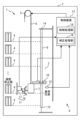
- FIG. 1 is a configuration diagram of an elevator 1 according to Embodiment 1. As shown in FIG. 1
- the elevator 1 is applied, for example, to a building 2 having multiple floors.
- a hoistway 3 for an elevator 1 is provided in a building 2 .
- the hoistway 3 is a vertically elongated space extending over a plurality of floors.
- a landing 4 for an elevator 1 is provided on each floor of the building 2 .
- a landing 4 is a place adjacent to the hoistway 3 .
- the elevator 1 comprises a hoisting machine 5 , a main rope 6 , a car 7 and a control system 8 .
- the hoist 5 includes a motor and a sheave.
- the hoist 5 is provided, for example, above or below the hoistway 3 .
- the hoist 5 may be arranged in the machine room.
- the motor of the hoist 5 is a device that generates driving force.
- the sheave of the hoisting machine 5 is connected to the rotating shaft of the motor of the hoisting machine 5 .
- the sheave of the hoisting machine 5 is rotated by the driving force generated by the motor of the hoisting machine 5 .
- the main rope 6 is wound around the sheave of the hoisting machine 5.
- the main rope 6 moves so as to be hoisted or paid out by the rotation of the sheave of the hoisting machine 5 .
- the main rope 6 supports the load of the car 7 on one side of the sheave of the hoist 5 .
- the car 7 is arranged in the hoistway 3.
- the car 7 travels vertically in the hoistway 3 as the hoisting machine 5 moves the main rope 6 .
- the car 7 is a device for transporting passengers on board between a plurality of floors by traveling up and down the hoistway 3 .
- a stop position is set at each floor.
- the stop position of the floor of the building 2 is the vertical position on the building 2 at which the car 7 is stopped on the floor.
- the control system 8 includes a detection tape 9 , a reader 10 , a detection device 11 , a temperature sensor 12 and a control device 13 .
- the detection tape 9 is a tape-shaped device that is long in one direction.
- Information representing the longitudinal position on the detection tape 9 is attached along the length of the detection tape 9 .
- Information representing the position in the longitudinal direction is attached to the detection tape 9 as magnetic data, for example, when the detection tape 9 is a magnetic tape.
- the information representing the longitudinal position may be provided on the surface of the detection tape 9 as, for example, a coded image containing a two-dimensional code.
- the detection tape 9 is arranged on the hoistway 3 so that its longitudinal direction is oriented vertically. One vertical end of the detection tape 9 is fixed to the hoistway 3 as a fixed end 14 .
- the other vertical end of the detection tape 9 is installed as a movable end 15 so as to be vertically movable with respect to the hoistway 3 .
- the upper end of the detection tape 9 is installed as the fixed end 14 .
- fixed end 14 is attached directly to the structure of building 2 .
- the structure of the building 2 includes, for example, inner walls of the hoistway 3, columns, or beams.
- the lower end of the detection tape 9 is installed as the movable end 15 .
- the movable end 15 is mounted via a spring so that the detection tape 9 can be tensioned, for example.
- the movable end 15 may be supported by a slide bearing or the like so as to be vertically slidable.
- the reading device 10 is a device that reads information representing the longitudinal position attached to the detection tape 9 .
- a reader 10 is installed in the car 7 .
- the reader 10 moves vertically in the hoistway 3 together with the car 7 .
- the reader 10 reads longitudinal position information from the detection tape 9 by, for example, a magnetic sensor, camera, or other device.
- the reading device 10 is connected to the control device 13 so as to output reading results.
- a reference position is set in advance in the control system 8 .
- the reference position is set on the side of the movable end 15 in the vertical direction of the hoistway 3 .
- the reference position is a vertical position on the building 2 .
- the lower end of the detection tape 9 is installed as the movable end 15 , so the reference position is set below the hoistway 3 .
- the reference position is set below the intermediate portion of the hoistway 3, for example.
- the reference position is set, for example, in the vicinity of the frequently stopped floor.
- the frequent stop floor is a floor set in advance as a floor on which the car 7 stops more frequently than other floors. Frequent stopping floors are, for example, floors where the car 7 stops more frequently than the average stop frequency of each floor of the building 2 .
- Frequent stop floors may be the standard floor of building 2, the entrance floor, the lobby floor, or the ground floor.
- a frequent stop floor may be, for example, a floor where a front desk or the like is located.
- the vicinity of the frequently-stopping floor is, for example, the range from the stop position of the car 7 at the frequently-stopping floor to the stop position of the car 7 at a floor adjacent to the frequently-stopping floor.
- the range may include stop positions of frequent stop floors.
- the reference position may be set to the stop position of the frequently stopped floor.
- the detection device 11 includes an object to be detected and a detector.
- a detector is a device that detects an object to be detected. One of the object to be detected and the detector is installed in the car 7 . The other of the object to be detected and the detector is installed at a reference position in the hoistway 3 . Of the object to be detected and the detector, the one installed in the car 7 moves vertically in the hoistway 3 as the car 7 travels.
- the detection device 11 detects that the car 7 is at the reference position by detecting the object to be detected by the detector.
- the detector is connected to the control device 13 so as to be able to output detection results.
- the sensing device 11 includes a sensed cam 16 and a sensing switch 17 .
- the detectable cam 16 is an example of a detectable body.
- the detected cam 16 is installed on the car 7 .
- the detection switch 17 detects the detected cam 16 by contact when the car 7 passes the reference position.
- the detection switch 17 is an example of a detector.
- the detection switch 17 is installed at the reference position.
- the sensing switch 17 is attached directly to the structure of the building 2 .
- the detection device 11 may include a detector that detects an object to be detected in a non-contact manner.
- the sensing device 11 may include, for example, an iron plate and a magnetic sensor, a light reflecting plate and a photoelectric sensor, or a marker and a camera as the object to be sensed and the detector.
- the detected object may be installed at the reference position. At this time, the object to be detected is directly attached to the structure of the building 2, for example.
- a detector is also installed in the car 7 .
- the control system 8 includes only one set of sensed object and detector of the sensing device 11 .
- the temperature sensor 12 is arranged in the hoistway 3.
- a temperature sensor 12 measures the temperature inside the hoistway 3 .
- the temperature sensor 12 is connected to the controller 13 so as to output the measurement results.
- the control device 13 is, for example, the control panel of the elevator 1.
- the control device 13 is provided, for example, above or below the hoistway 3 .
- the control device 13 may be arranged in the machine room.
- the control device 13 is connected to the hoisting machine 5 so as to be able to communicate control signals and the like.
- the control device 13 includes a control processor 18 and a correction processor 19 .
- the control processing unit 18 is a part that has a function to perform control processing of the elevator 1.
- the control processing includes operation control of the elevator 1, safety monitoring, and the like.
- the operation control of the elevator 1 includes, for example, running and stopping control of the car 7 .
- Safety monitoring of the elevator 1 includes, for example, terminal speed monitoring including a terminal floor forced reduction device, final limit switch, or monitoring of safety devices such as a door open protection device, and operation control of the elevator 1 based on the results thereof.
- the absolute position of car 7 is detected based on the longitudinal position on detection tape 9 read from detection tape 9 by reader 10 . That is, the control processing unit 18 performs the control processing of the elevator 1 using the longitudinal position read from the detection tape 9 as the absolute position of the car 7 in the vertical direction of the hoistway 3 .
- the correction processing unit 19 is a part equipped with a function for correcting the absolute position of the car 7.
- the correction processing unit 19 corrects the absolute position of the car 7, for example, when the detection device 11 detects that the car 7 is at the reference position.
- the correction processing unit 19 calculates the correction coefficient C by, for example, the following formula (1).
- y 0 represents the longitudinal position of the fixed end 14 of the detection tape 9 .
- y * represents the longitudinal position of the detection tape 9 read by the reader 10 when the detector 11 detects that the car 7 is at the reference position. That is, y 0 ⁇ y * is the detection from the fixed end 14 up to the position where the reading device 10 reads the information representing the longitudinal position when the detection device 11 detects that the car 7 is at the reference position. It represents the length on the tape 9.
- x 0 represents the installation position on the building 2 of the fixed end 14 of the detection tape 9 .
- x * represents a reference position. That is, x 0 -x * represents the length on the building 2 from the installation position of the fixed end 14 to the reference position.
- a correction coefficient C is calculated as a ratio of these lengths.
- the position y 0 of the fixed end 14 of the detection tape 9 on the detection tape 9 and the installation position x 0 of the fixed end 14 of the detection tape 9 on the building 2 are set in advance in the control system 8, for example, based on design values. It is
- the correction processing unit 19 corrects the absolute position x of the car 7 from the longitudinal position y on the detection tape 9 using the following equation (2).
- x(n) represents the stop position of the n-th floor of building 2, where n is a natural number equal to or less than the number of floors of building 2.
- the nth floor of building 2 may be a frequent stop floor, or some other floor.
- the stop position x(n) of each floor is set in advance in the control system 8 by, for example, a design value or adjustment or learning at the initial stage of installation.
- the control processing unit 18 controls the corrected absolute position x of the car 7 with the stop position x(n) of the n-th floor as the target position, thereby moving the car 7 to the stop position of the floor. stop.
- the correction processing unit 19 may perform correction without using a method of accurately proportional to the length on the building 2 or the length on the detection tape 9 or the like.
- the correction processing unit 19 may perform stepwise correction according to, for example, the length on the building 2 or the length on the detection tape 9 .
- the correction processing section 19 may perform correction according to the distribution characteristics.
- the distribution characteristic of the detection tape 9 is, for example, a characteristic representing the longitudinal distribution of the material, physical property value, size, shape, tension, or the like of the detection tape 9 .
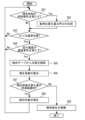
- FIG. 2 is a flow chart showing an example of the operation of the control system 8 according to the first embodiment.
- step S01 the correction processing unit 19 determines whether the current time satisfies preset time conditions.
- the time condition for the current time is, for example, a condition such as when the current time matches a preset correction time.
- the correction time may be a time set periodically.
- the time condition for the current time may be, for example, a condition such as when a preset time interval has elapsed since the time when the correction processing unit 19 performed the previous correction. If the current time satisfies the time condition, the process of control system 8 proceeds to step S02. If the current time does not satisfy the time condition, the process of control system 8 proceeds to step S03.
- the control processing unit 18 generates a call for the car 7 to pass through the reference position.
- the call generated by the control processing unit 18 is, for example, in the direction from the frequent stop floor to the adjacent floor when the reference position is in the range from the stop position of the frequent stop floor to the stop position of the adjacent floor. It is a call to run.
- the call generated by the control processing unit 18 is, for example, a call to drive the car 7 to the frequent stop floor or a call to make the car 7 pass the frequent stop floor. is.
- the control processing unit 18 causes the car 7 to travel in the hoistway 3 so as to respond to calls generated by the control processing unit 18 and calls registered by users. After that, the processing of the control system 8 proceeds to step S03.
- the control processing unit 18 controls the movement of the car 7 so that the car 7 passes the reference position at a lower speed than the running speed during normal operation when the car 7 responds to the call generated by the control processing unit 18. You can slow down and run. At this time, the control processing unit 18 may cause the car 7 to respond to the call after confirming that the user is not in the car 7 . Whether the user is not in the car 7 is confirmed, for example, based on the load measured by a weighing device (not shown) provided in the car 7 .
- step S03 the correction processing unit 19 determines whether the detection device 11 has detected that the car 7 is at the reference position.
- the car 7 may be running in response to a call registered by the user.
- the car 7 may run in response to a call generated by the control processor 18 .
- the car 7 may run without answering the call to move to a waiting position or the like. If the detection device 11 does not detect that the car 7 is at the reference position, the processing of the control system 8 proceeds to step S01. When the detection device 11 detects that the car 7 is at the reference position, the processing of the control system 8 proceeds to step S04.
- step S04 the correction processing unit 19 determines whether the travel speed of the car 7 when the detection device 11 detects that the car 7 is at the reference position satisfies a preset speed condition.
- the speed condition for the running speed of the car 7 is, for example, a condition such as when the running speed is lower than a preset speed threshold.
- the speed threshold is set, for example, as a speed capable of suppressing an error in reading the absolute position of the car 7 due to the influence of detection delay in the detection device 11 to an allowable error or less required for the control system 8 as a whole.
- the speed threshold is set, for example, to a speed lower than the rated traveling speed between floors during normal operation of the car 7 .
- the speed threshold may be a speed after deceleration when the car 7 is decelerated when it stops at the frequent stop floor.
- the speed condition is met when the car 7 stops at the frequent stop floor.
- step S05 the reading device 10 reads the longitudinal position y * on the detection tape 9.
- FIG. The correction processing unit 19 stores the longitudinal position y * on the detection tape 9 read by the reading device 10 . After that, the processing of the control system 8 proceeds to step S06.
- step S06 the correction processing unit 19 calculates the correction coefficient C using, for example, formula (1). After that, the processing of the control system 8 proceeds to step S07.
- step S07 the correction processing unit 19 calculates the amount of change in the current absolute position of the car 7 before and after the correction coefficient C is calculated.
- the amount of change before and after the calculation of the correction coefficient C may be calculated.
- the correction processing unit 19 calculates the absolute position x of the car 7 according to the equation (2) before the correction coefficient C is newly calculated in step S06 and the equation (2 ) from the absolute position x of the car 7 is calculated as the amount of change.
- the correction processing unit 19 may calculate the amount of change for the absolute position of the car 7 corresponding to the stop position of another floor.
- the correction processing section 19 may calculate the amount of change for the absolute position of the car 7 corresponding to the reference position.
- the correction processing unit 19 determines whether the calculated amount of change is within a preset allowable range.
- the correction processing unit 19 may calculate the amount of change for each function of the control processing unit 18 that requires the absolute position of the car 7 .
- the allowable range of variation may be set for each function of the control processing section 18 that requires the absolute position of the car 7 .
- the amount of variation or tolerance for the lift stroke may be used in the determination.
- the amount of change or allowable range for the floor closest to the movable end 15 of the detection tape 9 may be used for determination. If the amount of change is within the allowable range, the process of control system 8 proceeds to step S08. If the amount of change is not within the allowable range, the process of control system 8 proceeds to step S09.
- step S08 the correction processing unit 19 corrects the absolute position of the car 7 by, for example, updating the correction coefficient C used in formula (2). After that, the processing of the control system 8 proceeds to step S01.
- step S09 the control processing unit 18 determines that an abnormality has occurred in the control system 8.
- the control processing unit 18 determines, for example, that an abnormality has occurred in the detection tape 9 .
- the control processing unit 18 may issue a notification of the abnormality that has occurred.
- the notification is sent, for example, to an information center (not shown) that collects information on the elevator 1 through a communication network such as the Internet.
- the notification may be sent to, for example, a mobile terminal possessed by the manager of the elevator 1 through a communication network such as the Internet.
- the processing of the control system 8 then ends.
- the control system 8 includes the detection tape 9, the reading device 10, the detection device 11, and the control device 13.
- the detection tape 9 is arranged in the hoistway 3 extending over a plurality of floors of the building 2 so that the longitudinal direction thereof is the vertical direction.
- One vertical end of the detection tape 9 is fixed to the hoistway 3 as a fixed end 14 .
- the other end of the detection tape 9 in the vertical direction is installed as a movable end 15 so as to be movable in the vertical direction with respect to the hoistway 3 .
- the reader 10 is installed in a car 7 that runs vertically in the hoistway 3 .
- the reading device 10 reads the information representing the longitudinal position attached to the detection tape 9 .
- the detection device 11 includes a detected cam 16 and a detection switch 17 for detecting the detected cam 16 .
- a detection switch 17 is installed on the car 7 .
- the detected cam 16 is installed at the reference position.
- the reference position is a position preset on the side of the movable end 15 in the vertical direction of the hoistway 3 .
- the detection device 11 detects that the car 7 is at the reference position by detecting the detected cam 16 with the detection switch 17 .
- the control device 13 performs control processing of the car 7 using the longitudinal position read by the reading device 10 as the absolute position of the car 7 in the vertical direction in the hoistway 3 .
- the controller 13 corrects the absolute position of the car 7 using the longitudinal position read by the reader 10 when the detector 11 detects that the car 7 is at the reference position.
- the control system 8 can correct the absolute position of the car 7 each time the car 7 passes the reference position. , the influence of the positional deviation of the car 7 is suppressed.
- the length of the detection tape 9 can change over time, for example, due to expansion and contraction associated with temperature changes in the hoistway 3 .
- the elevator 1 is a see-through elevator for viewing, and the hoistway 3 is made of glass and has a high lift, the temperature change in the hoistway 3 can be large. In such an elevator 1, there is a possibility that the temperature change will be large for about one hour, and the expansion and contraction of the detection tape 9 may become 5 mm or more in about one hour. In such a case, the influence of expansion and contraction of the detection tape 9 cannot be ignored.
- the absolute position of the car 7 based on the information read from the detection tape 9 can be corrected when the car 7 passes the reference position. can be reduced by correction. As a result, the landing position of the car 7 is less likely to shift, and the user can use the elevator 1 more comfortably. Further, the object to be detected or the detector of the detection device 11 does not have to be arranged for each floor of the building 2 . Since one set of the object to be detected and the detector of the detection device 11 is sufficient, even in the elevator 1 having a high lift and a large number of floors, the equipment installation cost and maintenance cost can be reduced.
- the reference position is set in the range from the stop position of the frequent stop floor to the stop position of the adjacent floor.
- the range includes stop positions of frequent stop floors. Frequent stopping floors are preset as floors that the car 7 stops at more frequently than other floors.
- the control system 8 gets frequent opportunities to correct the absolute position of the car 7 .
- the control system 8 gets frequent opportunities to correct the absolute position of the car 7 .
- control device 13 generates a call for the car 7 to pass through the reference position when the current time satisfies a preset time condition.
- the control system 8 can control the absolute position of the car 7 at a preset timing. An opportunity for position correction becomes available. As a result, it is possible to suppress the elapse of a long period of time without correcting the absolute position. Therefore, even if the length of the detection tape 9 changes over time, the influence of the shift in the position of the car 7 can be effectively reduced. suppressed.
- control system 8 may include a temperature sensor 12.
- a temperature sensor 12 is installed in the hoistway 3 .
- the control processing unit 18 of the control device 13 may generate a call for the car 7 to pass through the reference position when the temperature measured by the temperature sensor 12 satisfies a preset temperature condition.
- the temperature condition for the temperature of the hoistway 3 measured by the temperature sensor 12 is, for example, when the temperature of the hoistway 3 exceeds a preset temperature threshold, or when the temperature of the hoistway 3 exceeds a preset temperature range. It is a condition such as when entering
- control system 8 will have the opportunity to correct the absolute position of the car 7 as needed due to temperature changes in the hoistway 3 . This prevents the absolute position from being corrected even if the temperature of the hoistway 3 changes. The influence of misalignment is suppressed more effectively.
- the control system 8 may generate a call based on both the time condition and the temperature condition. Control system 8 may generate a call based on only one of the time of day and temperature conditions. Alternatively, control system 8 may not generate calls based on time of day or temperature conditions.
- control device 13 determines the absolute position of the car 7 corresponding to the stop position of each floor on the condition that the speed of the car 7 when passing the reference position is lower than a preset speed threshold. is corrected. At this time, the control device 13 uses the longitudinal position read by the reading device 10 when the detection device 11 detects that the car 7 is at the reference position when the condition is satisfied.
- the reading of the absolute position of the car 7 used for correction is less susceptible to the detection delay in the detection device 11 . Therefore, the information used for correction can be obtained with higher accuracy, so that the accuracy of correction can be further improved.
- the control device 13 may correct the absolute position each time the car 7 passes the reference position regardless of the running speed of the car 7 .
- control device 13 determines the length from the fixed end 14 to the position where the reading device 10 reads the information representing the position in the longitudinal direction when the detection device 11 detects that the car 7 is at the reference position, and A ratio of the length from the installation position of the fixed end 14 to the reference position is calculated as a correction coefficient.
- the control device 13 corrects the absolute position of the car 7 using a value obtained by multiplying the length based on the fixed end 14 by the calculated correction coefficient.
- the control device 13 also determines whether the amount of change before and after the correction of the absolute position of the car 7 corresponding to at least one of the stop position and the reference position of each floor is within a preset allowable range. The control device 13 corrects the absolute position of the car 7 when the amount of change is within the allowable range.
- the correction processing unit 19 of the control device 13 may calculate the error of the absolute position of the car 7 corresponding to the stop position of any floor of the building 2 after calculating the correction coefficient.
- the correction processing unit 19 calculates, as an error, the difference between, for example, the stop position of the frequently stopped floor and the absolute position of the car 7 corresponding to the stop position.
- the correction processing unit 19 may calculate the error of the absolute position of the car 7 corresponding to the stop position of another floor.
- the correction processing section 19 may calculate the error of the absolute position of the car 7 corresponding to the reference position.
- the correction processing unit 19 determines whether the calculated error is within a preset allowable range.
- the permissible ranges set for the error in the absolute position of the car 7 and the amount of change before and after the correction may be different from each other or may be the same. If the error is within the permissible range, the controller 13 performs a correction of the absolute position of the car 7. On the other hand, if the error is not within the allowable range, the control device 13 determines that the control system 8 is abnormal.
- the control system 8 can detect an abnormality occurring in the detection tape 9 . It should be noted that the control system 8 may determine abnormality based on both the amount of change in the absolute position of the car 7 and the error. The control system 8 may determine the abnormality based on only one of the amount of change in the absolute position of the car 7 and the error. Alternatively, the control system 8 does not need to determine the abnormality based on the amount of change or error in the absolute position of the car 7 .
- the fixed end 14 of the detection tape 9 is attached to the structure of the building 2 .
- the detected object and the detector whichever is installed at the reference position, are attached to the structure of the building 2 .
- the installation position of the fixed end 14 of the detection tape 9 and the reference position are displaced by the shrinkage of the building 2 itself. become incorporated into As a result, the landing position of the car 7 is less likely to shift, and the user can use the elevator 1 more comfortably.
- the detection tape 9 may be installed on the hoistway 3 with the lower end as the fixed end 14 . At this time, the detection tape 9 is installed on the hoistway 3 with the upper end as the movable end 15 . In this case, the reference position is set above the hoistway 3 . Further, the frequent stop floor may be set to a transfer floor above the hoistway 3, for example.
- the correction processing unit 19 corrects the absolute position of the car 7 using the correction coefficient C for conversion of the position y on the detection tape 9 to the position x on the building 2.
- the correction processing unit 19 may correct the absolute position of the car 7 by updating the target position corresponding to the stop position of each floor using the correction coefficient C' as follows.
- the correction processing unit 19 calculates the correction coefficient C' by, for example, the following formula (3).
- the correction processing unit 19 calculates the longitudinal position y(n) on the detection tape 9 corresponding to the stop position of the n-th floor of the building 2 using the correction coefficient C' according to the following equation (4). Update.
- control processing unit 18 sets, for example, the position y(n) on the detection tape 9 corresponding to the n-th floor as the target position of the longitudinal position y read by the reading device 10 moving together with the car 7. By controlling the position of the car 7, the car is stopped at the stop position of the floor.
- FIG. 3 is a hardware configuration diagram of main parts of the control system 8 according to the first embodiment.
- the processing circuitry comprises at least one processor 100a and at least one memory 100b.
- the processing circuitry may comprise at least one piece of dedicated hardware 200 in conjunction with or in place of processor 100a and memory 100b.
- each function of the control system 8 is realized by software, firmware, or a combination of software and firmware. At least one of software and firmware is written as a program.
- the program is stored in memory 100b.
- the processor 100a realizes each function of the control system 8 by reading and executing the programs stored in the memory 100b.
- the processor 100a is also called a CPU (Central Processing Unit), a processing device, an arithmetic device, a microprocessor, a microcomputer, or a DSP.
- the memory 100b is composed of, for example, nonvolatile or volatile semiconductor memory such as RAM, ROM, flash memory, EPROM, and EEPROM.
- the processing circuit may be implemented, for example, as a single circuit, multiple circuits, a programmed processor, a parallel programmed processor, an ASIC, an FPGA, or a combination thereof.
- Each function of the control system 8 can be implemented by a processing circuit. Alternatively, each function of the control system 8 can be collectively realized by a processing circuit. A part of each function of the control system 8 may be realized by dedicated hardware 200 and the other part may be realized by software or firmware. Thus, the processing circuitry implements each function of control system 8 in dedicated hardware 200, software, firmware, or a combination thereof.
- control system according to the present disclosure can be applied to elevators.
Abstract
Provided is an elevator control system that can suppress the effects of car displacement, even when the length of a detection tape changes over time. A control system (8) has a detection tape (9) that is arranged on a hoistway (3) so as to have a fixed end (14) and a mobile end (15) in the vertical direction. A reading device (10) that is provided to a car (7) reads information on the detection tape (9) that indicates a position in the longitudinal direction. A detection device (11) detects that the car (7) is at a reference position that is on the mobile end (15) side of the hoistway (3) as a result of a detection switch (17) that is provided at the reference position detecting a detection target cam (16) that is provided to the car (7). A control device (13) performs control processing that treats the position read by the reading device (10) as the absolute position of the car (7). The control device (13) corrects the absolute position of the car (7) using the position in the longitudinal direction read by the reading device (10) at the time of detection by the detection device (11).
Description
本開示は、エレベーターの制御システムに関する。
This disclosure relates to an elevator control system.
特許文献1は、エレベーターの例を開示する。エレベーターにおいて、昇降路に磁気テープが配置される。かご位置検出装置は、昇降路におけるかごの位置を、磁気テープ上のデータを磁気センサで読み取ることで検出する。かご位置検出装置の調整において、かごが最上階および最下階に手動運転によって移動させられ、最上階および最下階の位置のデータが読み取られる。読み取られたデータと予め設定された最下階および最上階の設計上の位置との誤差に基づいて、予め設定された各階床の位置が補正される。
Patent Document 1 discloses an example of an elevator. In an elevator, magnetic tape is placed in the hoistway. The car position detection device detects the position of the car in the hoistway by reading data on the magnetic tape with a magnetic sensor. In calibrating the car position detector, the car is manually moved to the top and bottom floors and the position data of the top and bottom floors are read. Based on the error between the read data and the preset designed positions of the lowest floor and the highest floor, the preset positions of each floor are corrected.
しかしながら、昇降路に配置された磁気テープなどのかごの位置検出に用いられる検出テープの長さは、例えば昇降路の温度変化に伴う伸縮などによって経時変化することがある。特許文献1のエレベーターにおいて、手動運転によって調整された各階床に対応するかごの位置は、経時変化によって大きくずれる可能性がある。
However, the length of the detection tape used to detect the position of the car, such as the magnetic tape placed in the hoistway, may change over time due to, for example, expansion and contraction due to temperature changes in the hoistway. In the elevator of Patent Literature 1, there is a possibility that the positions of the cars corresponding to each floor that are adjusted by manual operation will largely deviate due to changes over time.
本開示は、このような課題の解決に係るものである。本開示は、検出テープの長さが経時変化する場合においても、かごの位置のずれによる影響を抑えられるエレベーターの制御システムを提供する。
The present disclosure relates to solving such problems. The present disclosure provides an elevator control system capable of suppressing the effects of car misalignment even when the length of the detection tape changes over time.
本開示に係るエレベーターの制御システムは、長手方向の位置を表す情報が長手方向にわたって付され、建物の複数の階床にわたる昇降路において長手方向が上下方向となるように配置され、上下方向の一端部が固定端として前記昇降路に対して固定して設置され、上下方向の他端部が可動端として前記昇降路に対して上下方向に可動に設置される検出テープと、前記昇降路を上下方向に走行するかごに設置され、前記検出テープに付された長手方向の位置を表す情報を読み取る読取装置と、被検知体および前記被検知体を検知する検知器を含み、前記被検知体および前記検知器の一方が前記かごに設置され、前記被検知体および前記検知器の他方が前記昇降路の上下方向における前記可動端側に予め設定された基準位置に設置され、前記検知器が前記被検知体を検知することで前記かごが前記基準位置にあることを検知する検知装置と、前記読取装置が読み取った長手方向の位置を前記かごの前記昇降路における上下方向の絶対位置として前記かごの制御処理を行い、前記かごが前記基準位置にあることを前記検知装置が検知したときに前記読取装置が読み取った長手方向の位置を用いて、前記かごの絶対位置を補正する制御装置と、を備える。
An elevator control system according to the present disclosure is provided with information representing a longitudinal position in the longitudinal direction, is arranged so that the longitudinal direction is the vertical direction in a hoistway over a plurality of floors of a building, and is arranged at one end in the vertical direction. a detection tape having a portion fixedly installed with respect to the hoistway as a fixed end and the other end in the vertical direction as a movable end installed movably in the vertical direction with respect to the hoistway; A reading device installed in a car traveling in a direction and reading information indicating a longitudinal position attached to the detection tape, a detector for detecting a detected object and the detected object, the detected object and One of the detectors is installed in the car, the other of the object to be detected and the detector is installed at a preset reference position on the movable end side in the vertical direction of the hoistway, and the detector is installed in the car. a detection device for detecting that the car is at the reference position by detecting an object to be detected; and correcting the absolute position of the car using the longitudinal position read by the reading device when the detecting device detects that the car is at the reference position; Prepare.
本開示に係るエレベーターの制御システムであれば、検出テープの長さが経時変化する場合においても、かごの位置のずれによる影響を抑えられる。
With the elevator control system according to the present disclosure, even if the length of the detection tape changes over time, it is possible to suppress the influence of the shift in the position of the car.
本開示の対象を実施するための形態について添付の図面を参照しながら説明する。各図において、同一または相当する部分には同一の符号を付して、重複する説明は適宜に簡略化または省略する。なお、本開示の対象は以下の実施の形態に限定されることなく、本開示の趣旨を逸脱しない範囲において、実施の形態の任意の構成要素の変形、または実施の形態の任意の構成要素の省略が可能である。
A mode for implementing the subject of the present disclosure will be described with reference to the attached drawings. In each figure, the same or corresponding parts are denoted by the same reference numerals, and overlapping descriptions are appropriately simplified or omitted. It should be noted that the subject of the present disclosure is not limited to the following embodiments, and modifications of any constituent elements of the embodiments, or modifications of any constituent elements of the embodiments, within the scope of the present disclosure. It can be omitted.
実施の形態1.
図1は、実施の形態1に係るエレベーター1の構成図である。 Embodiment 1.
FIG. 1 is a configuration diagram of an elevator 1 according to Embodiment 1. As shown in FIG.
図1は、実施の形態1に係るエレベーター1の構成図である。 Embodiment 1.
FIG. 1 is a configuration diagram of an elevator 1 according to Embodiment 1. As shown in FIG.
エレベーター1は、例えば複数の階床を有する建物2に適用される。建物2において、エレベーター1の昇降路3が設けられる。昇降路3は、複数の階床にわたる上下方向に長い空間である。建物2の各々の階床において、エレベーター1の乗場4が設けられる。乗場4は、昇降路3に隣接する場所である。エレベーター1は、巻上機5と、主ロープ6と、かご7と、制御システム8と、を備える。
The elevator 1 is applied, for example, to a building 2 having multiple floors. In a building 2 a hoistway 3 for an elevator 1 is provided. The hoistway 3 is a vertically elongated space extending over a plurality of floors. A landing 4 for an elevator 1 is provided on each floor of the building 2 . A landing 4 is a place adjacent to the hoistway 3 . The elevator 1 comprises a hoisting machine 5 , a main rope 6 , a car 7 and a control system 8 .
巻上機5は、モータおよびシーブを含む。巻上機5は、例えば昇降路3の上部または下部などに設けられる。例えば昇降路3の上部にエレベーター1の機械室が設けられるときに、巻上機5は、機械室に配置されてもよい。巻上機5のモータは、駆動力を発生させる装置である。巻上機5のシーブは、巻上機5のモータの回転軸に接続される。巻上機5のシーブは、巻上機5のモータが発生させる駆動力によって回転する。
The hoist 5 includes a motor and a sheave. The hoist 5 is provided, for example, above or below the hoistway 3 . For example, when the machine room of the elevator 1 is provided above the hoistway 3, the hoist 5 may be arranged in the machine room. The motor of the hoist 5 is a device that generates driving force. The sheave of the hoisting machine 5 is connected to the rotating shaft of the motor of the hoisting machine 5 . The sheave of the hoisting machine 5 is rotated by the driving force generated by the motor of the hoisting machine 5 .
主ロープ6は、巻上機5のシーブに巻き掛けられる。主ロープ6は、巻上機5のシーブの回転によって巻き上げられるように、または繰り出されるように移動する。主ロープ6は、巻上機5のシーブの一方側においてかご7の荷重を支持する。
The main rope 6 is wound around the sheave of the hoisting machine 5. The main rope 6 moves so as to be hoisted or paid out by the rotation of the sheave of the hoisting machine 5 . The main rope 6 supports the load of the car 7 on one side of the sheave of the hoist 5 .
かご7は、昇降路3に配置される。かご7は、巻上機5が主ロープ6を移動させることによって、昇降路3を上下方向に走行する。かご7は、昇降路3を上下方向に走行することで、乗車している利用者を複数の階床の間で輸送する装置である。各々の階床において、停止位置が設定される。建物2の階床の停止位置は、当該階床においてかご7を停止させる、建物2上の上下方向の位置である。
The car 7 is arranged in the hoistway 3. The car 7 travels vertically in the hoistway 3 as the hoisting machine 5 moves the main rope 6 . The car 7 is a device for transporting passengers on board between a plurality of floors by traveling up and down the hoistway 3 . At each floor, a stop position is set. The stop position of the floor of the building 2 is the vertical position on the building 2 at which the car 7 is stopped on the floor.
制御システム8は、検出テープ9と、読取装置10と、検知装置11と、温度センサ12と、制御装置13と、を備える。
The control system 8 includes a detection tape 9 , a reader 10 , a detection device 11 , a temperature sensor 12 and a control device 13 .
検出テープ9は、一方向に長いテープ状の機器である。検出テープ9において、検出テープ9上の長手方向の位置を表す情報が、長手方向にわたって付されている。長手方向の位置を表す情報は、例えば検出テープ9が磁気テープである場合に、磁気データとして検出テープ9に付されている。あるいは、長手方向の位置を表す情報は、例えば二次元コードを含む符号化画像などとして検出テープ9の表面上に付されていてもよい。検出テープ9は、長手方向が上下方向に向けられるように昇降路3に配置される。検出テープ9の上下方向の一端部は、固定端14として昇降路3に対して固定して設置される。また、検出テープ9の上下方向の他端部は、可動端15として昇降路3に対して上下方向に可動に設置される。この例において、検出テープ9の上端部が固定端14として設置される。この例において、固定端14は、建物2の構造体に直接取り付けられる。建物2の構造体は、例えば昇降路3の内壁、柱、または梁などを含む。また、検出テープ9の下端部が可動端15として設置される。可動端15は、例えば検出テープ9に張力を与えられるように、スプリングを介して設置される。あるいは、可動端15は、スライド軸受などによって上下方向にスライド可能に支持されるものであってもよい。
The detection tape 9 is a tape-shaped device that is long in one direction. Information representing the longitudinal position on the detection tape 9 is attached along the length of the detection tape 9 . Information representing the position in the longitudinal direction is attached to the detection tape 9 as magnetic data, for example, when the detection tape 9 is a magnetic tape. Alternatively, the information representing the longitudinal position may be provided on the surface of the detection tape 9 as, for example, a coded image containing a two-dimensional code. The detection tape 9 is arranged on the hoistway 3 so that its longitudinal direction is oriented vertically. One vertical end of the detection tape 9 is fixed to the hoistway 3 as a fixed end 14 . The other vertical end of the detection tape 9 is installed as a movable end 15 so as to be vertically movable with respect to the hoistway 3 . In this example, the upper end of the detection tape 9 is installed as the fixed end 14 . In this example, fixed end 14 is attached directly to the structure of building 2 . The structure of the building 2 includes, for example, inner walls of the hoistway 3, columns, or beams. Also, the lower end of the detection tape 9 is installed as the movable end 15 . The movable end 15 is mounted via a spring so that the detection tape 9 can be tensioned, for example. Alternatively, the movable end 15 may be supported by a slide bearing or the like so as to be vertically slidable.
読取装置10は、検出テープ9に付された長手方向の位置を表す情報を読み取る装置である。読取装置10は、かご7に設置される。読取装置10は、かご7とともに昇降路3において上下方向に移動する。読取装置10は、例えば磁気センサ、カメラ、またはその他の機器などによって検出テープ9から長手方向の位置の情報を読み取る。読取装置10は、読取結果を出力しうるように、制御装置13に接続する。
The reading device 10 is a device that reads information representing the longitudinal position attached to the detection tape 9 . A reader 10 is installed in the car 7 . The reader 10 moves vertically in the hoistway 3 together with the car 7 . The reader 10 reads longitudinal position information from the detection tape 9 by, for example, a magnetic sensor, camera, or other device. The reading device 10 is connected to the control device 13 so as to output reading results.
制御システム8において、基準位置が予め設定される。基準位置は、昇降路3の上下方向における可動端15側に設定される。基準位置は、建物2上の上下方向の位置である。この例において、検出テープ9の下端部が可動端15として設置されているので、基準位置は、昇降路3の下側に設定される。基準位置は、例えば、昇降路3の中間部より下方に設定される。基準位置は、例えば、頻繁停止階の近傍に設定される。ここで、頻繁停止階は、かご7が他の階床に停止するより頻繁に停止する階床として予め設定された階床である。頻繁停止階は、例えば、建物2の各階床の停止頻度の平均より頻繁にかご7が停止する階床などである。頻繁停止階は、建物2の基準階、玄関階、ロビー階、またはグランド階などである。頻繁停止階は、例えば、フロントデスクなどが設けられる階床などであってもよい。頻繁停止階の近傍は、例えば、頻繁停止階におけるかご7の停止位置から当該頻繁停止階の隣接階におけるかご7の停止位置までの範囲などである。ここで、当該範囲は、頻繁停止階の停止位置を含んでもよい。基準位置は、頻繁停止階の停止位置に設定されていてもよい。
A reference position is set in advance in the control system 8 . The reference position is set on the side of the movable end 15 in the vertical direction of the hoistway 3 . The reference position is a vertical position on the building 2 . In this example, the lower end of the detection tape 9 is installed as the movable end 15 , so the reference position is set below the hoistway 3 . The reference position is set below the intermediate portion of the hoistway 3, for example. The reference position is set, for example, in the vicinity of the frequently stopped floor. Here, the frequent stop floor is a floor set in advance as a floor on which the car 7 stops more frequently than other floors. Frequent stopping floors are, for example, floors where the car 7 stops more frequently than the average stop frequency of each floor of the building 2 . Frequent stop floors may be the standard floor of building 2, the entrance floor, the lobby floor, or the ground floor. A frequent stop floor may be, for example, a floor where a front desk or the like is located. The vicinity of the frequently-stopping floor is, for example, the range from the stop position of the car 7 at the frequently-stopping floor to the stop position of the car 7 at a floor adjacent to the frequently-stopping floor. Here, the range may include stop positions of frequent stop floors. The reference position may be set to the stop position of the frequently stopped floor.
検知装置11は、被検知体および検知器を含む。検知器は、被検知体を検知する機器である。被検知体および検知器の一方は、かご7に設置される。被検知体および検知器の他方は、昇降路3において基準位置に設置される。被検知体および検知器のうちかご7に設置される方は、かご7の走行とともに昇降路3を上下方向に移動する。検知装置11は、検知器が被検知体を検知することで、かご7が基準位置にあることを検知する。検知器は、検知結果を出力しうるように、制御装置13に接続する。この例において、検知装置11は、被検知カム16および検知スイッチ17を含む。被検知カム16は、被検知体の例である。被検知カム16は、かご7に設置される。検知スイッチ17は、かご7が基準位置を通過するときに、被検知カム16を接触によって検知する。検知スイッチ17は、検知器の例である。検知スイッチ17は、基準位置に設置される。この例において、検知スイッチ17は、建物2の構造体に直接取り付けられる。なお、検知装置11は、非接触で被検知体を検知する検知器を含んでもよい。検知装置11は、被検知体および検知器として、例えば鉄板および磁気センサ、光反射板および光電センサ、またはマーカおよびカメラなどを含んでもよい。また、被検知体は、基準位置に設置されてもよい。このとき、被検知体は、例えば建物2の構造体に直接取り付けられる。また、検知器は、かご7に設置される。この例において、制御システム8は、検知装置11の被検知体および検知器の組を、1つのみ含む。
The detection device 11 includes an object to be detected and a detector. A detector is a device that detects an object to be detected. One of the object to be detected and the detector is installed in the car 7 . The other of the object to be detected and the detector is installed at a reference position in the hoistway 3 . Of the object to be detected and the detector, the one installed in the car 7 moves vertically in the hoistway 3 as the car 7 travels. The detection device 11 detects that the car 7 is at the reference position by detecting the object to be detected by the detector. The detector is connected to the control device 13 so as to be able to output detection results. In this example, the sensing device 11 includes a sensed cam 16 and a sensing switch 17 . The detectable cam 16 is an example of a detectable body. The detected cam 16 is installed on the car 7 . The detection switch 17 detects the detected cam 16 by contact when the car 7 passes the reference position. The detection switch 17 is an example of a detector. The detection switch 17 is installed at the reference position. In this example, the sensing switch 17 is attached directly to the structure of the building 2 . Note that the detection device 11 may include a detector that detects an object to be detected in a non-contact manner. The sensing device 11 may include, for example, an iron plate and a magnetic sensor, a light reflecting plate and a photoelectric sensor, or a marker and a camera as the object to be sensed and the detector. Further, the detected object may be installed at the reference position. At this time, the object to be detected is directly attached to the structure of the building 2, for example. A detector is also installed in the car 7 . In this example, the control system 8 includes only one set of sensed object and detector of the sensing device 11 .
温度センサ12は、昇降路3に配置される。温度センサ12は、昇降路3内の温度を計測する。温度センサ12は、計測結果を出力しうるように、制御装置13に接続する。
The temperature sensor 12 is arranged in the hoistway 3. A temperature sensor 12 measures the temperature inside the hoistway 3 . The temperature sensor 12 is connected to the controller 13 so as to output the measurement results.
制御装置13は、例えばエレベーター1の制御盤などである。制御装置13は、例えば昇降路3の上部または下部などに設けられる。例えば昇降路3の上部にエレベーター1の機械室が設けられるときに、制御装置13は、機械室に配置されてもよい。制御装置13は、制御信号などを通信しうるように、巻上機5に接続する。制御装置13は、制御処理部18と、補正処理部19と、を備える。
The control device 13 is, for example, the control panel of the elevator 1. The control device 13 is provided, for example, above or below the hoistway 3 . For example, when the machine room of the elevator 1 is provided above the hoistway 3, the control device 13 may be arranged in the machine room. The control device 13 is connected to the hoisting machine 5 so as to be able to communicate control signals and the like. The control device 13 includes a control processor 18 and a correction processor 19 .
制御処理部18は、エレベーター1の制御処理を行う機能を搭載する部分である。制御処理は、エレベーター1の動作制御または安全監視などを含む。エレベーター1の動作制御は、例えばかご7の走行および停止の制御などを含む。エレベーター1の安全監視は、例えば、終端階強制減速装置を含む終端部速度監視、ファイナルリミットスイッチ、または戸開走行保護装置などの安全装置の監視およびその結果に基づくエレベーター1の動作制御などを含む。この例において、かご7の絶対位置は、読取装置10が検出テープ9から読み取った検出テープ9上の長手方向の位置に基づいて検出される。すなわち、制御処理部18は、検出テープ9から読み取られた長手方向の位置を昇降路3の上下方向におけるかご7の絶対位置として、エレベーター1の制御処理を行う。
The control processing unit 18 is a part that has a function to perform control processing of the elevator 1. The control processing includes operation control of the elevator 1, safety monitoring, and the like. The operation control of the elevator 1 includes, for example, running and stopping control of the car 7 . Safety monitoring of the elevator 1 includes, for example, terminal speed monitoring including a terminal floor forced reduction device, final limit switch, or monitoring of safety devices such as a door open protection device, and operation control of the elevator 1 based on the results thereof. . In this example, the absolute position of car 7 is detected based on the longitudinal position on detection tape 9 read from detection tape 9 by reader 10 . That is, the control processing unit 18 performs the control processing of the elevator 1 using the longitudinal position read from the detection tape 9 as the absolute position of the car 7 in the vertical direction of the hoistway 3 .
補正処理部19は、かご7の絶対位置を補正する機能を搭載する部分である。補正処理部19は、例えばかご7が基準位置にいることを検知装置11が検知するときに、かご7の絶対位置の補正を行う。補正処理部19は、例えば、次の式(1)によって補正係数Cを算出する。
The correction processing unit 19 is a part equipped with a function for correcting the absolute position of the car 7. The correction processing unit 19 corrects the absolute position of the car 7, for example, when the detection device 11 detects that the car 7 is at the reference position. The correction processing unit 19 calculates the correction coefficient C by, for example, the following formula (1).
ここで、y0は、検出テープ9の固定端14の長手方向の位置を表す。y*は、かご7が基準位置にいることを検知装置11が検知するときに読取装置10が読み取った検出テープ9の長手方向の位置を表す。すなわち、y0-y*は、かご7が基準位置にあることを検知装置11が検知したときに読取装置10が長手方向の位置を表す情報を読み取った箇所までの、固定端14からの検出テープ9上の長さを表す。また、x0は、検出テープ9の固定端14の建物2上の設置位置を表す。x*は、基準位置を表す。すなわち、x0-x*は、固定端14の設置位置から基準位置までの建物2上の長さを表す。補正係数Cは、これらの長さの比として算出される。なお、検出テープ9の固定端14の検出テープ9上の位置y0、および検出テープ9の固定端14の建物2上の設置位置x0は、例えば、設計値などにより制御システム8において予め設定されている。
Here, y 0 represents the longitudinal position of the fixed end 14 of the detection tape 9 . y * represents the longitudinal position of the detection tape 9 read by the reader 10 when the detector 11 detects that the car 7 is at the reference position. That is, y 0 −y * is the detection from the fixed end 14 up to the position where the reading device 10 reads the information representing the longitudinal position when the detection device 11 detects that the car 7 is at the reference position. It represents the length on the tape 9. Also, x 0 represents the installation position on the building 2 of the fixed end 14 of the detection tape 9 . x * represents a reference position. That is, x 0 -x * represents the length on the building 2 from the installation position of the fixed end 14 to the reference position. A correction coefficient C is calculated as a ratio of these lengths. The position y 0 of the fixed end 14 of the detection tape 9 on the detection tape 9 and the installation position x 0 of the fixed end 14 of the detection tape 9 on the building 2 are set in advance in the control system 8, for example, based on design values. It is
この例において、補正処理部19は、次の式(2)などを用いて、検出テープ9上の長手方向の位置yからかご7の絶対位置xを補正する。
In this example, the correction processing unit 19 corrects the absolute position x of the car 7 from the longitudinal position y on the detection tape 9 using the following equation (2).
ここで、建物2の階床の数以下の自然数をnとして、x(n)は、建物2のn番目の階床の停止位置を表す。建物2のn番目の階床は、頻繁停止階、またはその他の階床などである。各々の階床の停止位置x(n)は、例えば、設計値、または据付初期の調整もしくは学習などにより制御システム8において予め設定されている。制御処理部18は、例えば、n番目の階床の停止位置x(n)を目標位置として、補正されたかご7の絶対位置xを制御することで、かご7を当該階床の停止位置に停止させる。
Here, x(n) represents the stop position of the n-th floor of building 2, where n is a natural number equal to or less than the number of floors of building 2. The nth floor of building 2 may be a frequent stop floor, or some other floor. The stop position x(n) of each floor is set in advance in the control system 8 by, for example, a design value or adjustment or learning at the initial stage of installation. For example, the control processing unit 18 controls the corrected absolute position x of the car 7 with the stop position x(n) of the n-th floor as the target position, thereby moving the car 7 to the stop position of the floor. stop.
なお、補正処理部19は、建物2上の長さまたは検出テープ9上の長さなどに正確に比例させる方法によらずに補正を行ってもよい。補正処理部19は、例えば、建物2上の長さまたは検出テープ9上の長さなどに応じた段階的な補正を行ってもよい。あるいは、検出テープ9の分布特性が既知である場合に、補正処理部19は、当該分布特性に従って補正を行ってもよい。検出テープ9の分布特性は、例えば、検出テープ9の材質、物性値、寸法、形状、または張力などの長手方向の分布を表す特性である。
It should be noted that the correction processing unit 19 may perform correction without using a method of accurately proportional to the length on the building 2 or the length on the detection tape 9 or the like. The correction processing unit 19 may perform stepwise correction according to, for example, the length on the building 2 or the length on the detection tape 9 . Alternatively, if the distribution characteristics of the detection tape 9 are known, the correction processing section 19 may perform correction according to the distribution characteristics. The distribution characteristic of the detection tape 9 is, for example, a characteristic representing the longitudinal distribution of the material, physical property value, size, shape, tension, or the like of the detection tape 9 .
続いて、図2を用いて、制御システム8の動作の例を説明する。
図2は、実施の形態1に係る制御システム8の動作の例を示すフローチャートである。 Next, an example of the operation of thecontrol system 8 will be explained using FIG.
FIG. 2 is a flow chart showing an example of the operation of thecontrol system 8 according to the first embodiment.
図2は、実施の形態1に係る制御システム8の動作の例を示すフローチャートである。 Next, an example of the operation of the
FIG. 2 is a flow chart showing an example of the operation of the
ステップS01において、補正処理部19は、現在時刻が予め設定された時刻条件を満たすかを判定する。現在時刻についての時刻条件は、例えば、予め設定された補正時刻に現在時刻が一致するとき、などの条件である。補正時刻は、定期的に設定された時刻であってもよい。あるいは、現在時刻についての時刻条件は、例えば、補正処理部19が前回の補正を行った時刻から予め設定された時間間隔が経過したとき、などの条件であってもよい。現在時刻が時刻条件を満たす場合に、制御システム8の処理は、ステップS02に進む。現在時刻が時刻条件を満たさない場合に、制御システム8の処理は、ステップS03に進む。
In step S01, the correction processing unit 19 determines whether the current time satisfies preset time conditions. The time condition for the current time is, for example, a condition such as when the current time matches a preset correction time. The correction time may be a time set periodically. Alternatively, the time condition for the current time may be, for example, a condition such as when a preset time interval has elapsed since the time when the correction processing unit 19 performed the previous correction. If the current time satisfies the time condition, the process of control system 8 proceeds to step S02. If the current time does not satisfy the time condition, the process of control system 8 proceeds to step S03.
ステップS02において、制御処理部18は、かご7が基準位置を通る呼びを発生させる。ここで制御処理部18が発生させる呼びは、基準位置が頻繁停止階の停止位置から隣接する階床の停止位置までの範囲である場合に、例えば頻繁停止階から当該隣接する階床の方向に走行する呼びなどである。あるいは、基準位置が頻繁停止階の停止位置である場合に、制御処理部18が発生させる呼びは、例えば頻繁停止階までかご7を走行させる呼び、またはかご7に頻繁停止階を通過させる呼びなどである。制御処理部18は、制御処理部18が発生させた呼び、および利用者によって登録された呼びに応答させるように、昇降路3においてかご7を走行させる。その後、制御システム8の処理は、ステップS03に進む。
At step S02, the control processing unit 18 generates a call for the car 7 to pass through the reference position. Here, the call generated by the control processing unit 18 is, for example, in the direction from the frequent stop floor to the adjacent floor when the reference position is in the range from the stop position of the frequent stop floor to the stop position of the adjacent floor. It is a call to run. Alternatively, when the reference position is the stop position of the frequent stop floor, the call generated by the control processing unit 18 is, for example, a call to drive the car 7 to the frequent stop floor or a call to make the car 7 pass the frequent stop floor. is. The control processing unit 18 causes the car 7 to travel in the hoistway 3 so as to respond to calls generated by the control processing unit 18 and calls registered by users. After that, the processing of the control system 8 proceeds to step S03.
なお、制御処理部18は、制御処理部18が発生させた呼びにかご7を応答させるときに、通常運転時の走行速度より遅い低速でかご7が基準位置を通過するように、かご7の速度を落として走行させてもよい。このとき、制御処理部18は、利用者がかご7に乗車していないことを確認した後に、当該呼びにかご7を応答させてもよい。利用者がかご7に乗車していないことは、例えば、かご7に設けられる図示されない秤装置が計測する積載荷重などに基づいて確認される。
The control processing unit 18 controls the movement of the car 7 so that the car 7 passes the reference position at a lower speed than the running speed during normal operation when the car 7 responds to the call generated by the control processing unit 18. You can slow down and run. At this time, the control processing unit 18 may cause the car 7 to respond to the call after confirming that the user is not in the car 7 . Whether the user is not in the car 7 is confirmed, for example, based on the load measured by a weighing device (not shown) provided in the car 7 .
ステップS03において、補正処理部19は、かご7が基準位置にあることを検知装置11が検知したかを判定する。このとき、かご7は、利用者が登録した呼びに応答して走行していてもよい。あるいは、かご7は、制御処理部18が発生された呼びに応答して走行していてもよい。あるいは、かご7は、待機位置などに移動するために呼びに応答せずに走行していてもよい。かご7が基準位置にあると検知装置11が検知しない場合に、制御システム8の処理は、ステップS01に進む。かご7が基準位置にあると検知装置11が検知する場合に、制御システム8の処理は、ステップS04に進む。
In step S03, the correction processing unit 19 determines whether the detection device 11 has detected that the car 7 is at the reference position. At this time, the car 7 may be running in response to a call registered by the user. Alternatively, the car 7 may run in response to a call generated by the control processor 18 . Alternatively, the car 7 may run without answering the call to move to a waiting position or the like. If the detection device 11 does not detect that the car 7 is at the reference position, the processing of the control system 8 proceeds to step S01. When the detection device 11 detects that the car 7 is at the reference position, the processing of the control system 8 proceeds to step S04.
ステップS04において、補正処理部19は、かご7が基準位置にあることを検知装置11が検知したときのかご7の走行速度が予め設定された速度条件を満たすかを判定する。かご7の走行速度についての速度条件は、例えば、走行速度が予め設定された速度閾値より低いとき、などの条件である。ここで、速度閾値は、例えば、検知装置11における検知遅延の影響によるかご7の絶対位置の読取りなどの誤差を制御システム8全体として要求される許容誤差以下に抑制可能な速度として設定される。速度閾値は、例えば、かご7の通常運転時の階床間の定格の走行速度より遅い速度に設定される。また、速度閾値は、頻繁停止階にかご7が停止するときに減速するときの減速後の速度などであってもよい。この場合に、かご7が頻繁停止階に停止するときに速度条件が満たされるようになる。かご7の走行速度が速度条件を満たさない場合に、制御システム8の処理は、ステップS01に進む。かご7の走行速度が速度条件を満たす場合に、制御システム8の処理は、ステップS05に進む。
In step S04, the correction processing unit 19 determines whether the travel speed of the car 7 when the detection device 11 detects that the car 7 is at the reference position satisfies a preset speed condition. The speed condition for the running speed of the car 7 is, for example, a condition such as when the running speed is lower than a preset speed threshold. Here, the speed threshold is set, for example, as a speed capable of suppressing an error in reading the absolute position of the car 7 due to the influence of detection delay in the detection device 11 to an allowable error or less required for the control system 8 as a whole. The speed threshold is set, for example, to a speed lower than the rated traveling speed between floors during normal operation of the car 7 . Further, the speed threshold may be a speed after deceleration when the car 7 is decelerated when it stops at the frequent stop floor. In this case, the speed condition is met when the car 7 stops at the frequent stop floor. When the running speed of the car 7 does not satisfy the speed condition, the processing of the control system 8 proceeds to step S01. If the travel speed of the car 7 satisfies the speed condition, the processing of the control system 8 proceeds to step S05.
ステップS05において、読取装置10は、検出テープ9上の長手方向の位置y*を読み取る。補正処理部19は、読取装置10が読み取った検出テープ9上の長手方向の位置y*を記憶する。その後、制御システム8の処理は、ステップS06に進む。
In step S05, the reading device 10 reads the longitudinal position y * on the detection tape 9. FIG. The correction processing unit 19 stores the longitudinal position y * on the detection tape 9 read by the reading device 10 . After that, the processing of the control system 8 proceeds to step S06.
ステップS06において、補正処理部19は、例えば式(1)などを用いて、補正係数Cを算出する。その後、制御システム8の処理は、ステップS07に進む。
In step S06, the correction processing unit 19 calculates the correction coefficient C using, for example, formula (1). After that, the processing of the control system 8 proceeds to step S07.
ステップS07において、補正処理部19は、現在のかご7の絶対位置について、補正係数Cの算出の前後における変化量を算出する。あるいは、建物2の頻繁停止階を含むいずれかの階床の停止位置に対応するかご7の絶対位置について、補正係数Cの算出の前後における変化量を算出してもよい。補正処理部19は、例えば、ステップS06において新たに補正係数Cを算出する前の式(2)によるかご7の絶対位置xと、ステップS06において新たに補正係数Cを算出した後の式(2)によるかご7の絶対位置xとの差分を、変化量として算出する。なお、補正処理部19は、他の階床の停止位置に対応するかご7の絶対位置について変化量を算出してもよい。あるいは、補正処理部19は、基準位置に対応するかご7の絶対位置について変化量を算出してもよい。補正処理部19は、算出した変化量が予め設定された許容範囲内かを判定する。なお、補正処理部19は、かご7の絶対位置を必要とする制御処理部18の機能ごとに変化量を算出してもよい。補正処理部19において、変化量の許容範囲は、かご7の絶対位置を必要とする制御処理部18の機能ごとに設定されていてもよい。例えば、終端部速度監視について、昇降行程に対する変化量または許容範囲が判定に用いられてもよい。あるいは、戸開走行保護装置について、検出テープ9の可動端15に最も近い階床に対する変化量または許容範囲が判定に用いられてもよい。変化量が許容範囲内である場合に、制御システム8の処理は、ステップS08に進む。変化量が許容範囲内でない場合に、制御システム8の処理は、ステップS09に進む。
In step S07, the correction processing unit 19 calculates the amount of change in the current absolute position of the car 7 before and after the correction coefficient C is calculated. Alternatively, for the absolute position of the car 7 corresponding to the stop position of any floor including the frequently stopped floor of the building 2, the amount of change before and after the calculation of the correction coefficient C may be calculated. For example, the correction processing unit 19 calculates the absolute position x of the car 7 according to the equation (2) before the correction coefficient C is newly calculated in step S06 and the equation (2 ) from the absolute position x of the car 7 is calculated as the amount of change. Note that the correction processing unit 19 may calculate the amount of change for the absolute position of the car 7 corresponding to the stop position of another floor. Alternatively, the correction processing section 19 may calculate the amount of change for the absolute position of the car 7 corresponding to the reference position. The correction processing unit 19 determines whether the calculated amount of change is within a preset allowable range. Note that the correction processing unit 19 may calculate the amount of change for each function of the control processing unit 18 that requires the absolute position of the car 7 . In the correction processing section 19 , the allowable range of variation may be set for each function of the control processing section 18 that requires the absolute position of the car 7 . For example, for terminal velocity monitoring, the amount of variation or tolerance for the lift stroke may be used in the determination. Alternatively, for the door open protection device, the amount of change or allowable range for the floor closest to the movable end 15 of the detection tape 9 may be used for determination. If the amount of change is within the allowable range, the process of control system 8 proceeds to step S08. If the amount of change is not within the allowable range, the process of control system 8 proceeds to step S09.
ステップS08において、補正処理部19は、例えば式(2)に用いる補正係数Cを更新することなどによって、かご7の絶対位置を補正する。その後、制御システム8の処理は、ステップS01に進む。
In step S08, the correction processing unit 19 corrects the absolute position of the car 7 by, for example, updating the correction coefficient C used in formula (2). After that, the processing of the control system 8 proceeds to step S01.
ステップS09において、制御処理部18は、制御システム8に異常が発生したと判定する。制御処理部18は、例えば、検出テープ9に異常が発生したと判定する。制御処理部18は、発生した異常の発報を行ってもよい。発報は、例えば、エレベーター1の情報を収集する図示されない情報センターなどに、インターネットなどの通信網を通じて行われる。あるいは、発報は、例えば、エレベーター1の管理者が所持する携帯端末などに、インターネットなどの通信網を通じて行われてもよい。その後、制御システム8の処理は、終了する。
In step S09, the control processing unit 18 determines that an abnormality has occurred in the control system 8. The control processing unit 18 determines, for example, that an abnormality has occurred in the detection tape 9 . The control processing unit 18 may issue a notification of the abnormality that has occurred. The notification is sent, for example, to an information center (not shown) that collects information on the elevator 1 through a communication network such as the Internet. Alternatively, the notification may be sent to, for example, a mobile terminal possessed by the manager of the elevator 1 through a communication network such as the Internet. The processing of the control system 8 then ends.
以上に説明したように、実施の形態1に係る制御システム8は、検出テープ9と、読取装置10と、検知装置11と、制御装置13と、を備える。検出テープ9において、長手方向の位置を表す情報が長手方向にわたって付される。検出テープ9は、建物2の複数の階床にわたる昇降路3において、長手方向が上下方向となるように配置される。検出テープ9の上下方向の一端部は、固定端14として昇降路3に対して固定して設置される。検出テープ9の上下方向の他端部は、可動端15として昇降路3に対して上下方向に可動に設置される。読取装置10は、昇降路3を上下方向に走行するかご7に設置される。読取装置10は、検出テープ9に付された長手方向の位置を表す情報を読み取る。検知装置11は、被検知カム16および被検知カム16を検知する検知スイッチ17を含む。検知スイッチ17は、かご7に設置される。被検知カム16は、基準位置に設置される。基準位置は、昇降路3の上下方向における可動端15側に予め設定された位置である。検知装置11は、検知スイッチ17が被検知カム16を検知することでかご7が基準位置にあることを検知する。制御装置13は、読取装置10が読み取った長手方向の位置をかご7の昇降路3における上下方向の絶対位置としてかご7の制御処理を行う。制御装置13は、かご7が基準位置にあることを検知装置11が検知したときに読取装置10が読み取った長手方向の位置を用いて、かご7の絶対位置を補正する。
As described above, the control system 8 according to Embodiment 1 includes the detection tape 9, the reading device 10, the detection device 11, and the control device 13. On the detection tape 9, information representing the position in the longitudinal direction is attached along the longitudinal direction. The detection tape 9 is arranged in the hoistway 3 extending over a plurality of floors of the building 2 so that the longitudinal direction thereof is the vertical direction. One vertical end of the detection tape 9 is fixed to the hoistway 3 as a fixed end 14 . The other end of the detection tape 9 in the vertical direction is installed as a movable end 15 so as to be movable in the vertical direction with respect to the hoistway 3 . The reader 10 is installed in a car 7 that runs vertically in the hoistway 3 . The reading device 10 reads the information representing the longitudinal position attached to the detection tape 9 . The detection device 11 includes a detected cam 16 and a detection switch 17 for detecting the detected cam 16 . A detection switch 17 is installed on the car 7 . The detected cam 16 is installed at the reference position. The reference position is a position preset on the side of the movable end 15 in the vertical direction of the hoistway 3 . The detection device 11 detects that the car 7 is at the reference position by detecting the detected cam 16 with the detection switch 17 . The control device 13 performs control processing of the car 7 using the longitudinal position read by the reading device 10 as the absolute position of the car 7 in the vertical direction in the hoistway 3 . The controller 13 corrects the absolute position of the car 7 using the longitudinal position read by the reader 10 when the detector 11 detects that the car 7 is at the reference position.
このような構成により、制御システム8は、かご7が基準位置を通るたびにかご7の絶対位置の補正を行うことができるようになるので、検出テープ9の長さが経時変化する場合においても、かご7の位置のずれによる影響が抑えられる。検出テープ9の長さは、例えば昇降路3の温度変化に伴う伸縮などによって経時変化しうる。例えばエレベーター1が展望用のシースルーエレベーターなどの昇降路3がガラス張りで高揚程のエレベーターである場合などにおいて、昇降路3の温度変化が大きくなりうる。このようなエレベーター1においては、1時間程度の時間の間の温度変化が大きくなる可能性があり、検出テープ9の伸縮が例えば1時間程度で5mm以上となる場合もある。このような場合に、検出テープ9の伸縮の影響が無視できなくなる。制御システム8においては、検出テープ9から読み取られた情報に基づくかご7の絶対位置が基準位置をかご7が通るときに補正できるようになるので、検出テープ9の長さが経時変化する場合においても補正によってその影響を低減できるようになる。これにより、かご7の着床位置のずれなどが生じにくくなり、利用者がより快適にエレベーター1を利用できるようになる。また、検知装置11の被検知体または検知器などは、建物2の階床ごとに配置する必要がない。検知装置11の被検知体および検知器は1組あれば十分であるので、特に高揚程で階床の数が多いエレベーター1においても、機器の設置コストおよび保守コストなどが抑えられる。
With such a configuration, the control system 8 can correct the absolute position of the car 7 each time the car 7 passes the reference position. , the influence of the positional deviation of the car 7 is suppressed. The length of the detection tape 9 can change over time, for example, due to expansion and contraction associated with temperature changes in the hoistway 3 . For example, when the elevator 1 is a see-through elevator for viewing, and the hoistway 3 is made of glass and has a high lift, the temperature change in the hoistway 3 can be large. In such an elevator 1, there is a possibility that the temperature change will be large for about one hour, and the expansion and contraction of the detection tape 9 may become 5 mm or more in about one hour. In such a case, the influence of expansion and contraction of the detection tape 9 cannot be ignored. In the control system 8, the absolute position of the car 7 based on the information read from the detection tape 9 can be corrected when the car 7 passes the reference position. can be reduced by correction. As a result, the landing position of the car 7 is less likely to shift, and the user can use the elevator 1 more comfortably. Further, the object to be detected or the detector of the detection device 11 does not have to be arranged for each floor of the building 2 . Since one set of the object to be detected and the detector of the detection device 11 is sufficient, even in the elevator 1 having a high lift and a large number of floors, the equipment installation cost and maintenance cost can be reduced.
また、制御システム8において、基準位置は、頻繁停止階の停止位置から隣接する階床の停止位置までの範囲に設定される。ここで、当該範囲は頻繁停止階の停止位置を含む。頻繁停止階は、かご7が他の階床に停止するより頻繁に停止する階床として予め設定される。
In addition, in the control system 8, the reference position is set in the range from the stop position of the frequent stop floor to the stop position of the adjacent floor. Here, the range includes stop positions of frequent stop floors. Frequent stopping floors are preset as floors that the car 7 stops at more frequently than other floors.
このような構成により、通常運転においてかご7が基準位置を頻繁に通るようになる。すなわち、通常運転において、制御システム8は、かご7の絶対位置の補正の機会を頻繁に得られるようになる。これにより、検出テープ9の長さが経時変化する場合においても、かご7の位置のずれによる影響がより効果的に抑えられる。
With this configuration, the car 7 frequently passes through the reference position during normal operation. In other words, during normal operation, the control system 8 gets frequent opportunities to correct the absolute position of the car 7 . As a result, even if the length of the detection tape 9 changes with time, the influence of the shift in the position of the car 7 can be suppressed more effectively.
また、制御装置13は、現在時刻が予め設定された時刻条件を満たすときに、かご7が基準位置を通る呼びを発生させる。
Also, the control device 13 generates a call for the car 7 to pass through the reference position when the current time satisfies a preset time condition.
このような構成により、例えば利用者の呼びなどによってかご7が上層階などの基準位置から離れた範囲で走行している場合においても、制御システム8は、予め設定されたタイミングでかご7の絶対位置の補正の機会を得られるようになる。これにより、絶対位置の補正が行われないまま長時間経過することが抑制されるため、検出テープ9の長さが経時変化する場合においても、かご7の位置のずれによる影響がより効果的に抑えられる。
With such a configuration, even when the car 7 is traveling in a range away from the reference position such as an upper floor due to a user's call, the control system 8 can control the absolute position of the car 7 at a preset timing. An opportunity for position correction becomes available. As a result, it is possible to suppress the elapse of a long period of time without correcting the absolute position. Therefore, even if the length of the detection tape 9 changes over time, the influence of the shift in the position of the car 7 can be effectively reduced. suppressed.
なお、制御システム8は、温度センサ12を備えてもよい。温度センサ12は、昇降路3に設置される。このとき、制御装置13の制御処理部18は、温度センサ12が計測する温度が予め設定された温度条件を満たすときに、かご7が基準位置を通る呼びを発生させてもよい。温度センサ12が計測する昇降路3の温度についての温度条件は、例えば、昇降路3の温度が予め設定された温度閾値を超えたとき、または、昇降路3の温度が予め設定された温度範囲に入ったとき、などの条件である。
Note that the control system 8 may include a temperature sensor 12. A temperature sensor 12 is installed in the hoistway 3 . At this time, the control processing unit 18 of the control device 13 may generate a call for the car 7 to pass through the reference position when the temperature measured by the temperature sensor 12 satisfies a preset temperature condition. The temperature condition for the temperature of the hoistway 3 measured by the temperature sensor 12 is, for example, when the temperature of the hoistway 3 exceeds a preset temperature threshold, or when the temperature of the hoistway 3 exceeds a preset temperature range. It is a condition such as when entering
このような構成により、昇降路3の温度変化による必要に応じて、制御システム8は、かご7の絶対位置の補正の機会を得られるようになる。これにより、昇降路3に温度変化が生じても絶対位置の補正が行われないままになることが抑制されるため、検出テープ9の長さが経時変化する場合においても、かご7の位置のずれによる影響がより効果的に抑えられる。なお、制御システム8は、時刻条件および温度条件の両方に基づいて呼びを発生させてもよい。制御システム8は、時刻条件および温度条件の一方のみに基づいて呼びを発生させてもよい。あるいは、制御システム8は、時刻条件または温度条件に基づく呼びを発生させなくてもよい。
With this configuration, the control system 8 will have the opportunity to correct the absolute position of the car 7 as needed due to temperature changes in the hoistway 3 . This prevents the absolute position from being corrected even if the temperature of the hoistway 3 changes. The influence of misalignment is suppressed more effectively. Note that the control system 8 may generate a call based on both the time condition and the temperature condition. Control system 8 may generate a call based on only one of the time of day and temperature conditions. Alternatively, control system 8 may not generate calls based on time of day or temperature conditions.
また、制御装置13は、基準位置を通過するときのかご7の速度が予め設定された速度閾値より遅い速度であることを条件として、各々の階床の停止位置に対応するかご7の絶対位置を補正する。このとき、制御装置13は、当該補正に、当該条件を満たす場合にかご7が基準位置にあることを検知装置11が検知したときに読取装置10が読み取った長手方向の位置を用いる。
Further, the control device 13 determines the absolute position of the car 7 corresponding to the stop position of each floor on the condition that the speed of the car 7 when passing the reference position is lower than a preset speed threshold. is corrected. At this time, the control device 13 uses the longitudinal position read by the reading device 10 when the detection device 11 detects that the car 7 is at the reference position when the condition is satisfied.
このような構成により、補正に用いられるかご7の絶対位置の読取りが検知装置11における検知遅延の影響を受けにくくなる。このため、補正に用いられる情報がより高い精度で得られるようになるので、補正の精度がより高められるようになる。なお、制御装置13は、かご7の走行速度に関わらずに、かご7が基準位置を通るたびに絶対位置の補正を行ってもよい。
With such a configuration, the reading of the absolute position of the car 7 used for correction is less susceptible to the detection delay in the detection device 11 . Therefore, the information used for correction can be obtained with higher accuracy, so that the accuracy of correction can be further improved. Note that the control device 13 may correct the absolute position each time the car 7 passes the reference position regardless of the running speed of the car 7 .
また、制御装置13は、かご7が基準位置にあることを検知装置11が検知したときに読取装置10が長手方向の位置を表す情報を読み取った箇所までの固定端14からの長さ、および基準位置までの固定端14の設置位置からの長さの比を、補正係数として算出する。制御装置13は、固定端14を基準とした長さに算出した補正係数を乗じた値を用いて、かご7の絶対位置を補正する。
In addition, the control device 13 determines the length from the fixed end 14 to the position where the reading device 10 reads the information representing the position in the longitudinal direction when the detection device 11 detects that the car 7 is at the reference position, and A ratio of the length from the installation position of the fixed end 14 to the reference position is calculated as a correction coefficient. The control device 13 corrects the absolute position of the car 7 using a value obtained by multiplying the length based on the fixed end 14 by the calculated correction coefficient.
このような構成により、単一の補正係数の算出により、かご7の絶対位置などの補正が容易にできるようになる。
With such a configuration, it becomes possible to easily correct the absolute position of the car 7 by calculating a single correction coefficient.
また、制御装置13は、各々の階床の停止位置および基準位置の少なくともいずれかに対応するかご7の絶対位置の補正前後の変化量が、予め設定された許容範囲内かを判定する。制御装置13は、当該変化量が許容範囲内である場合に、かご7の絶対位置を補正する。
The control device 13 also determines whether the amount of change before and after the correction of the absolute position of the car 7 corresponding to at least one of the stop position and the reference position of each floor is within a preset allowable range. The control device 13 corrects the absolute position of the car 7 when the amount of change is within the allowable range.
このような構成により、制御システム8において、検出テープ9に生じた異常が検出されるようになる。検出テープ9に生じた異常に対応しやすくなるので、エレベーター1がより安定に運行されるようになる。
With such a configuration, in the control system 8, an abnormality occurring in the detection tape 9 can be detected. Since it becomes easier to deal with the abnormality occurring in the detection tape 9, the elevator 1 can be operated more stably.
なお、制御装置13の補正処理部19は、補正係数を算出した後などに、建物2のいずれかの階床の停止位置に対応するかご7の絶対位置の誤差を算出してもよい。補正処理部19は、例えば、頻繁停止階の停止位置と、当該停止位置に対応するかご7の絶対位置との差分を、誤差として算出する。なお、補正処理部19は、他の階床の停止位置に対応するかご7の絶対位置の誤差を算出してもよい。あるいは、補正処理部19は、基準位置に対応するかご7の絶対位置の誤差を算出してもよい。補正処理部19は、算出した誤差が予め設定された許容範囲内かを判定する。ここで、かご7の絶対位置の誤差および補正前後の変化量について設定される許容範囲は、互いに異なるものであってもよいし、同様なものであってもよい。誤差が許容範囲内である場合に、制御装置13は、かご7の絶対位置の補正を実行する。一方、誤差が許容範囲内でない場合に、制御装置13は、制御システム8に異常が発生したと判定する。
Note that the correction processing unit 19 of the control device 13 may calculate the error of the absolute position of the car 7 corresponding to the stop position of any floor of the building 2 after calculating the correction coefficient. The correction processing unit 19 calculates, as an error, the difference between, for example, the stop position of the frequently stopped floor and the absolute position of the car 7 corresponding to the stop position. Note that the correction processing unit 19 may calculate the error of the absolute position of the car 7 corresponding to the stop position of another floor. Alternatively, the correction processing section 19 may calculate the error of the absolute position of the car 7 corresponding to the reference position. The correction processing unit 19 determines whether the calculated error is within a preset allowable range. Here, the permissible ranges set for the error in the absolute position of the car 7 and the amount of change before and after the correction may be different from each other or may be the same. If the error is within the permissible range, the controller 13 performs a correction of the absolute position of the car 7. On the other hand, if the error is not within the allowable range, the control device 13 determines that the control system 8 is abnormal.
このような構成によっても、制御システム8において、検出テープ9に生じた異常が検出されるようになる。なお、制御システム8は、かご7の絶対位置の変化量および誤差の両方に基づいて異常の判定を行ってもよい。制御システム8は、かご7の絶対位置の変化量および誤差の一方のみに基づいて異常の判定を行ってもよい。あるいは、制御システム8は、かご7の絶対位置の変化量または誤差に基づいて異常の判定を行わなくてもよい。
With such a configuration as well, the control system 8 can detect an abnormality occurring in the detection tape 9 . It should be noted that the control system 8 may determine abnormality based on both the amount of change in the absolute position of the car 7 and the error. The control system 8 may determine the abnormality based on only one of the amount of change in the absolute position of the car 7 and the error. Alternatively, the control system 8 does not need to determine the abnormality based on the amount of change or error in the absolute position of the car 7 .
また、検出テープ9の固定端14は、建物2の構造体に取り付けられる。検知装置11において、被検知体および検知器のうち基準位置に設置される方は、建物2の構造体に取り付けられる。
Also, the fixed end 14 of the detection tape 9 is attached to the structure of the building 2 . In the detection device 11 , the detected object and the detector, whichever is installed at the reference position, are attached to the structure of the building 2 .
このような構成により、検出テープ9の固定端14の設置位置および基準位置が建物2自体の縮みなどによって変位するようになるので、建物2自体の縮みなどの影響がかご7の絶対位置の補正に取り込まれるようになる。これにより、かご7の着床位置のずれなどが生じにくくなり、利用者がより快適にエレベーター1を利用できるようになる。
With such a configuration, the installation position of the fixed end 14 of the detection tape 9 and the reference position are displaced by the shrinkage of the building 2 itself. become incorporated into As a result, the landing position of the car 7 is less likely to shift, and the user can use the elevator 1 more comfortably.
なお、検出テープ9は、下端部を固定端14として昇降路3に設置されてもよい。このとき、検出テープ9は、上端部を可動端15として昇降路3に設置される。この場合に、基準位置は、昇降路3の上側に設定される。また、頻繁停止階は、例えば昇降路3の上方の乗換階などに設定されていてもよい。
Note that the detection tape 9 may be installed on the hoistway 3 with the lower end as the fixed end 14 . At this time, the detection tape 9 is installed on the hoistway 3 with the upper end as the movable end 15 . In this case, the reference position is set above the hoistway 3 . Further, the frequent stop floor may be set to a transfer floor above the hoistway 3, for example.
また、以上に示した例において、補正処理部19は、検出テープ9上の位置yの建物2上の位置xへの換算に補正係数Cを用いてかご7の絶対位置の補正を行っているが、かご7の絶対位置の補正の方法はこれに限定されない。補正処理部19は、例えば次のように補正係数C´を用いて各々の階床の停止位置に対応する目標位置を更新することで、かご7の絶対位置の補正を行ってもよい。補正処理部19は、例えば、次の式(3)によって補正係数C´を算出する。
In the example shown above, the correction processing unit 19 corrects the absolute position of the car 7 using the correction coefficient C for conversion of the position y on the detection tape 9 to the position x on the building 2. However, the method of correcting the absolute position of the car 7 is not limited to this. The correction processing unit 19 may correct the absolute position of the car 7 by updating the target position corresponding to the stop position of each floor using the correction coefficient C' as follows. The correction processing unit 19 calculates the correction coefficient C' by, for example, the following formula (3).
補正処理部19は、次の式(4)によって、補正係数C´を用いて、建物2のn番目の階床の停止位置に対応する検出テープ9上の長手方向の位置y(n)を更新する。
The correction processing unit 19 calculates the longitudinal position y(n) on the detection tape 9 corresponding to the stop position of the n-th floor of the building 2 using the correction coefficient C' according to the following equation (4). Update.
このとき、制御処理部18は、例えば、n番目の階床に対応する検出テープ9上の位置y(n)を、かご7とともに移動する読取装置10が読み取る長手方向の位置yの目標位置としてかご7の位置を制御することで、かごを当該階床の停止位置に停止させる。
At this time, the control processing unit 18 sets, for example, the position y(n) on the detection tape 9 corresponding to the n-th floor as the target position of the longitudinal position y read by the reading device 10 moving together with the car 7. By controlling the position of the car 7, the car is stopped at the stop position of the floor.
続いて、図3を用いて、制御システム8のハードウェア構成の例について説明する。
図3は、実施の形態1に係る制御システム8の主要部のハードウェア構成図である。 Next, an example of the hardware configuration of thecontrol system 8 will be explained using FIG.
FIG. 3 is a hardware configuration diagram of main parts of thecontrol system 8 according to the first embodiment.
図3は、実施の形態1に係る制御システム8の主要部のハードウェア構成図である。 Next, an example of the hardware configuration of the
FIG. 3 is a hardware configuration diagram of main parts of the
制御システム8の各機能は、処理回路により実現し得る。処理回路は、少なくとも1つのプロセッサ100aと少なくとも1つのメモリ100bとを備える。処理回路は、プロセッサ100aおよびメモリ100bと共に、あるいはそれらの代用として、少なくとも1つの専用ハードウェア200を備えてもよい。
Each function of the control system 8 can be realized by a processing circuit. The processing circuitry comprises at least one processor 100a and at least one memory 100b. The processing circuitry may comprise at least one piece of dedicated hardware 200 in conjunction with or in place of processor 100a and memory 100b.
処理回路がプロセッサ100aとメモリ100bとを備える場合、制御システム8の各機能は、ソフトウェア、ファームウェア、またはソフトウェアとファームウェアとの組み合わせで実現される。ソフトウェアおよびファームウェアの少なくとも一方は、プログラムとして記述される。そのプログラムはメモリ100bに格納される。プロセッサ100aは、メモリ100bに記憶されたプログラムを読み出して実行することにより、制御システム8の各機能を実現する。
When the processing circuit includes a processor 100a and a memory 100b, each function of the control system 8 is realized by software, firmware, or a combination of software and firmware. At least one of software and firmware is written as a program. The program is stored in memory 100b. The processor 100a realizes each function of the control system 8 by reading and executing the programs stored in the memory 100b.
プロセッサ100aは、CPU(Central Processing Unit)、処理装置、演算装置、マイクロプロセッサ、マイクロコンピュータ、DSPともいう。メモリ100bは、例えば、RAM、ROM、フラッシュメモリ、EPROM、EEPROMなどの、不揮発性または揮発性の半導体メモリなどにより構成される。
The processor 100a is also called a CPU (Central Processing Unit), a processing device, an arithmetic device, a microprocessor, a microcomputer, or a DSP. The memory 100b is composed of, for example, nonvolatile or volatile semiconductor memory such as RAM, ROM, flash memory, EPROM, and EEPROM.
処理回路が専用ハードウェア200を備える場合、処理回路は、例えば、単一回路、複合回路、プログラム化したプロセッサ、並列プログラム化したプロセッサ、ASIC、FPGA、またはこれらの組み合わせで実現される。
When the processing circuit comprises dedicated hardware 200, the processing circuit may be implemented, for example, as a single circuit, multiple circuits, a programmed processor, a parallel programmed processor, an ASIC, an FPGA, or a combination thereof.
制御システム8の各機能は、それぞれ処理回路で実現することができる。あるいは、制御システム8の各機能は、まとめて処理回路で実現することもできる。制御システム8の各機能について、一部を専用ハードウェア200で実現し、他部をソフトウェアまたはファームウェアで実現してもよい。このように、処理回路は、専用ハードウェア200、ソフトウェア、ファームウェア、またはこれらの組み合わせで制御システム8の各機能を実現する。
Each function of the control system 8 can be implemented by a processing circuit. Alternatively, each function of the control system 8 can be collectively realized by a processing circuit. A part of each function of the control system 8 may be realized by dedicated hardware 200 and the other part may be realized by software or firmware. Thus, the processing circuitry implements each function of control system 8 in dedicated hardware 200, software, firmware, or a combination thereof.
本開示に係る制御システムは、エレベーターに適用できる。
The control system according to the present disclosure can be applied to elevators.
1 エレベーター、 2 建物、 3 昇降路、 4 乗場、 5 巻上機、 6 主ロープ、 7 かご、 8 制御システム、 9 検出テープ、 10 読取装置、 11 検知装置、 12 温度センサ、 13 制御装置、 14 固定端、 15 可動端、 16 被検知カム、 17 検知スイッチ、 18 制御処理部、 19 補正処理部、 100a プロセッサ、 100b メモリ、 200 専用ハードウェア
1 elevator, 2 building, 3 hoistway, 4 platform, 5 hoisting machine, 6 main rope, 7 car, 8 control system, 9 detection tape, 10 reader, 11 detection device, 12 temperature sensor, 13 control device, 14 Fixed end 15 Movable end 16 Cam to be detected 17 Detection switch 18 Control processing unit 19 Correction processing unit 100a Processor 100b Memory 200 Dedicated hardware
Claims (11)
- 長手方向の位置を表す情報が長手方向にわたって付され、建物の複数の階床にわたる昇降路において長手方向が上下方向となるように配置され、上下方向の一端部が固定端として前記昇降路に対して固定して設置され、上下方向の他端部が可動端として前記昇降路に対して上下方向に可動に設置される検出テープと、
前記昇降路を上下方向に走行するかごに設置され、前記検出テープに付された長手方向の位置を表す情報を読み取る読取装置と、
被検知体および前記被検知体を検知する検知器を含み、前記被検知体および前記検知器の一方が前記かごに設置され、前記被検知体および前記検知器の他方が前記昇降路の上下方向における前記可動端側に予め設定された基準位置に設置され、前記検知器が前記被検知体を検知することで前記かごが前記基準位置にあることを検知する検知装置と、
前記読取装置が読み取った長手方向の位置を前記かごの前記昇降路における上下方向の絶対位置として前記かごの制御処理を行い、前記かごが前記基準位置にあることを前記検知装置が検知したときに前記読取装置が読み取った長手方向の位置を用いて、前記かごの絶対位置を補正する制御装置と、
を備える、エレベーターの制御システム。 Information indicating the position in the longitudinal direction is attached along the longitudinal direction, and the hoistway is arranged so that the longitudinal direction is the vertical direction in a hoistway that extends over a plurality of floors of the building, and one end in the vertical direction is fixed to the hoistway as a fixed end. a detection tape that is fixedly installed on the hoistway, and the other end in the vertical direction is installed as a movable end to be movable in the vertical direction with respect to the hoistway;
a reading device installed in a car that travels vertically in the hoistway to read information indicating a longitudinal position attached to the detection tape;
An object to be detected and a detector for detecting the object to be detected, one of the object to be detected and the detector being installed in the car, and the other of the object to be detected and the detector being installed in the vertical direction of the hoistway a detection device that is installed at a reference position preset on the movable end side of the above, and detects that the car is at the reference position by detecting the detected object with the detector;
When the car control process is performed using the longitudinal position read by the reading device as the absolute position of the car in the vertical direction in the hoistway, and the detecting device detects that the car is at the reference position. a control device that corrects the absolute position of the car using the longitudinal position read by the reading device;
A control system for an elevator, comprising: - 前記基準位置は、前記かごが他の階床に停止するより頻繁に停止する階床として予め設定された頻繁停止階の停止位置から隣接する階床の停止位置までの範囲に設定される、
請求項1にエレベーターの制御システム。 The reference position is set in a range from a stop position of a frequent stop floor preset as a floor on which the car stops more frequently than other floors to a stop position of an adjacent floor,
A control system for an elevator according to claim 1. - 前記制御装置は、現在時刻が予め設定された時刻条件を満たすときに、前記かごが前記基準位置を通る呼びを発生させる、
請求項1または請求項2に記載のエレベーターの制御システム。 The control device generates a call for the car to pass through the reference position when the current time satisfies a preset time condition.
The elevator control system according to claim 1 or 2. - 前記昇降路に設置される温度センサ
を備え、
前記制御装置は、前記温度センサが計測する温度が予め設定された温度条件を満たすときに、前記かごが前記基準位置を通る呼びを発生させる、
請求項1または請求項2に記載のエレベーターの制御システム。 a temperature sensor installed in the hoistway,
The control device generates a call for the car to pass through the reference position when the temperature measured by the temperature sensor satisfies a preset temperature condition.
The elevator control system according to claim 1 or 2. - 前記制御装置は、前記基準位置を通過するときの前記かごの速度が予め設定された速度閾値より遅い速度であることを条件として、当該条件を満たす場合に前記かごが前記基準位置にあることを前記検知装置が検知したときに前記読取装置が読み取った長手方向の位置を用いて、前記かごの絶対位置を補正する、
請求項1から請求項4のいずれか一項に記載のエレベーターの制御システム。 The control device determines that the car is at the reference position when the condition is satisfied, on the condition that the speed of the car when passing the reference position is lower than a preset speed threshold. correcting the absolute position of the car using the longitudinal position read by the reading device when detected by the sensing device;
The elevator control system according to any one of claims 1 to 4. - 前記制御装置は、前記かごが前記基準位置にあることを前記検知装置が検知したときに前記読取装置が長手方向の位置を表す情報を読み取った箇所までの前記固定端からの長さ、および前記基準位置までの前記固定端の設置位置からの長さの比を補正係数として算出し、前記固定端を基準とした長さに前記補正係数を乗じた値を用いて、前記かごの絶対位置を補正する、
請求項1から請求項5のいずれか一項に記載のエレベーターの制御システム。 The control device controls the length from the fixed end to the position where the reading device reads the information representing the position in the longitudinal direction when the detection device detects that the car is at the reference position, and the The ratio of the length from the installation position of the fixed end to the reference position is calculated as a correction coefficient, and the absolute position of the car is calculated using the value obtained by multiplying the length with reference to the fixed end by the correction coefficient. to correct,
The elevator control system according to any one of claims 1 to 5. - 前記制御装置は、前記複数の階床の各々の停止位置および前記基準位置の少なくともいずれかに対応する前記かごの絶対位置の補正前後の変化量が予め設定された許容範囲内かを判定し、当該変化量が前記許容範囲内である場合に前記かごの絶対位置を補正する、
請求項1から請求項6のいずれか一項に記載のエレベーターの制御システム。 The control device determines whether an amount of change before and after correction of the absolute position of the car corresponding to at least one of the stop position of each of the plurality of floors and the reference position is within a preset allowable range, correcting the absolute position of the car if the amount of change is within the allowable range;
The elevator control system according to any one of claims 1 to 6. - 前記制御装置は、前記複数の階床の各々の停止位置および前記基準位置の少なくともいずれかに対応する前記かごの絶対位置の補正前後の変化量が予め設定された許容範囲内かを判定し、当該変化量が前記許容範囲内でない場合に異常が発生したと判定する、
請求項1から請求項6のいずれか一項に記載のエレベーターの制御システム。 The control device determines whether an amount of change before and after correction of the absolute position of the car corresponding to at least one of the stop position of each of the plurality of floors and the reference position is within a preset allowable range, Determining that an abnormality has occurred when the amount of change is not within the allowable range;
The elevator control system according to any one of claims 1 to 6. - 前記制御装置は、前記複数の階床の各々の停止位置および前記基準位置の少なくともいずれかに対応する前記かごの絶対位置の誤差が予め設定された許容範囲内かを判定し、当該誤差が前記許容範囲内である場合に前記かごの絶対位置を補正する、
請求項1から請求項6のいずれか一項に記載のエレベーターの制御システム。 The control device determines whether an error in the absolute position of the car corresponding to at least one of the stop position of each of the plurality of floors and the reference position is within a preset allowable range. correcting the absolute position of the car if within tolerance;
The elevator control system according to any one of claims 1 to 6. - 前記制御装置は、前記複数の階床の各々の停止位置および前記基準位置の少なくともいずれかに対応する前記かごの絶対位置の誤差が予め設定された許容範囲内かを判定し、当該誤差が前記許容範囲内でない場合に異常が発生したと判定する、
請求項1から請求項6のいずれか一項に記載のエレベーターの制御システム。 The control device determines whether an error in the absolute position of the car corresponding to at least one of the stop position of each of the plurality of floors and the reference position is within a preset allowable range. If it is not within the allowable range, it is determined that an abnormality has occurred.
The elevator control system according to any one of claims 1 to 6. - 前記固定端は、前記建物の構造体に取り付けられ、
前記被検知体および前記検知器のうち前記基準位置に設置される方は、前記建物の構造体に取り付けられる、
請求項1から請求項10のいずれか一項に記載のエレベーターの制御システム。 wherein the fixed end is attached to the building structure;
The one of the object to be detected and the detector installed at the reference position is attached to the structure of the building,
The elevator control system according to any one of claims 1 to 10.
Priority Applications (1)
| Application Number | Priority Date | Filing Date | Title |
|---|---|---|---|
| PCT/JP2022/003244 WO2023144985A1 (en) | 2022-01-28 | 2022-01-28 | Elevator control system |
Applications Claiming Priority (1)
| Application Number | Priority Date | Filing Date | Title |
|---|---|---|---|
| PCT/JP2022/003244 WO2023144985A1 (en) | 2022-01-28 | 2022-01-28 | Elevator control system |
Publications (1)
| Publication Number | Publication Date |
|---|---|
| WO2023144985A1 true WO2023144985A1 (en) | 2023-08-03 |
Family
ID=87471290
Family Applications (1)
| Application Number | Title | Priority Date | Filing Date |
|---|---|---|---|
| PCT/JP2022/003244 WO2023144985A1 (en) | 2022-01-28 | 2022-01-28 | Elevator control system |
Country Status (1)
| Country | Link |
|---|---|
| WO (1) | WO2023144985A1 (en) |
Citations (6)
| Publication number | Priority date | Publication date | Assignee | Title |
|---|---|---|---|---|
| WO2014184869A1 (en) * | 2013-05-14 | 2014-11-20 | 三菱電機株式会社 | Elevator device, and control method therefor |
| JP2019116337A (en) * | 2017-12-26 | 2019-07-18 | フジテック株式会社 | Double deck elevator |
| JP2019199347A (en) * | 2018-05-18 | 2019-11-21 | 株式会社日立ビルシステム | Elevator car position identifying device and identifying method thereof |
| WO2020065788A1 (en) * | 2018-09-26 | 2020-04-02 | 株式会社日立製作所 | Elevator control device and elevator using same |
| WO2020115900A1 (en) * | 2018-12-07 | 2020-06-11 | 株式会社日立製作所 | Elevator device |
| JP2021066567A (en) * | 2019-10-24 | 2021-04-30 | 株式会社日立ビルシステム | Elevator device |
-
2022
- 2022-01-28 WO PCT/JP2022/003244 patent/WO2023144985A1/en unknown
Patent Citations (6)
| Publication number | Priority date | Publication date | Assignee | Title |
|---|---|---|---|---|
| WO2014184869A1 (en) * | 2013-05-14 | 2014-11-20 | 三菱電機株式会社 | Elevator device, and control method therefor |
| JP2019116337A (en) * | 2017-12-26 | 2019-07-18 | フジテック株式会社 | Double deck elevator |
| JP2019199347A (en) * | 2018-05-18 | 2019-11-21 | 株式会社日立ビルシステム | Elevator car position identifying device and identifying method thereof |
| WO2020065788A1 (en) * | 2018-09-26 | 2020-04-02 | 株式会社日立製作所 | Elevator control device and elevator using same |
| WO2020115900A1 (en) * | 2018-12-07 | 2020-06-11 | 株式会社日立製作所 | Elevator device |
| JP2021066567A (en) * | 2019-10-24 | 2021-04-30 | 株式会社日立ビルシステム | Elevator device |
Similar Documents
| Publication | Publication Date | Title |
|---|---|---|
| CN110615331B (en) | Position reference device for elevator | |
| KR100681078B1 (en) | Elevator device | |
| JP4368854B2 (en) | Elevator equipment | |
| JP6203068B2 (en) | Elevator car landing position deviation detection device and elevator car landing position deviation detection method | |
| JP2015113180A (en) | Adjustment method of car position detection device of elevator | |
| CN111132920B (en) | Method for limiting the elongation of a suspension device of an elevator car and elevator system | |
| CN112384462B (en) | Elevator diagnosis system | |
| JP6683184B2 (en) | elevator | |
| CN111498626B (en) | Controlling movement of an elevator car | |
| JP2011116541A (en) | Double-deck elevator and method of controlling the same | |
| US9266699B2 (en) | Elevator system and operation thereof | |
| CN109476445B (en) | Elevator control device and control method | |
| JP5673368B2 (en) | Double deck elevator | |
| WO2023144985A1 (en) | Elevator control system | |
| JP6419638B2 (en) | Car elevator | |
| CN112623896A (en) | Elevator floor height correction method | |
| CN113767059B (en) | Slip detection system for elevator | |
| WO2021002107A1 (en) | Elevator device | |
| WO2011089691A1 (en) | Elevator apparatus | |
| KR102182981B1 (en) | System for detecting position of an elevator car | |
| JP5007498B2 (en) | Elevator Weigher Diagnosis Method | |
| JP2002003118A (en) | Elevator device | |
| JP6806108B2 (en) | Double deck elevator | |
| JP2007230760A (en) | Elevator | |
| CN113056429B (en) | Elevator control device |
Legal Events
| Date | Code | Title | Description |
|---|---|---|---|
| 121 | Ep: the epo has been informed by wipo that ep was designated in this application |
Ref document number: 22923849 Country of ref document: EP Kind code of ref document: A1 |