WO2023127607A1 - ピストンリング及びピストンリングセット - Google Patents
ピストンリング及びピストンリングセット Download PDFInfo
- Publication number
- WO2023127607A1 WO2023127607A1 PCT/JP2022/046957 JP2022046957W WO2023127607A1 WO 2023127607 A1 WO2023127607 A1 WO 2023127607A1 JP 2022046957 W JP2022046957 W JP 2022046957W WO 2023127607 A1 WO2023127607 A1 WO 2023127607A1
- Authority
- WO
- WIPO (PCT)
- Prior art keywords
- piston ring
- peripheral surface
- curved
- ear
- width
- Prior art date
- Legal status (The legal status is an assumption and is not a legal conclusion. Google has not performed a legal analysis and makes no representation as to the accuracy of the status listed.)
- Ceased
Links
Images





Classifications
-
- F—MECHANICAL ENGINEERING; LIGHTING; HEATING; WEAPONS; BLASTING
- F16—ENGINEERING ELEMENTS AND UNITS; GENERAL MEASURES FOR PRODUCING AND MAINTAINING EFFECTIVE FUNCTIONING OF MACHINES OR INSTALLATIONS; THERMAL INSULATION IN GENERAL
- F16J—PISTONS; CYLINDERS; SEALINGS
- F16J9/00—Piston-rings, e.g. non-metallic piston-rings, seats therefor; Ring sealings of similar construction
- F16J9/06—Piston-rings, e.g. non-metallic piston-rings, seats therefor; Ring sealings of similar construction using separate springs or elastic elements expanding the rings; Springs therefor ; Expansion by wedging
-
- F—MECHANICAL ENGINEERING; LIGHTING; HEATING; WEAPONS; BLASTING
- F16—ENGINEERING ELEMENTS AND UNITS; GENERAL MEASURES FOR PRODUCING AND MAINTAINING EFFECTIVE FUNCTIONING OF MACHINES OR INSTALLATIONS; THERMAL INSULATION IN GENERAL
- F16J—PISTONS; CYLINDERS; SEALINGS
- F16J9/00—Piston-rings, e.g. non-metallic piston-rings, seats therefor; Ring sealings of similar construction
- F16J9/12—Details
-
- F—MECHANICAL ENGINEERING; LIGHTING; HEATING; WEAPONS; BLASTING
- F16—ENGINEERING ELEMENTS AND UNITS; GENERAL MEASURES FOR PRODUCING AND MAINTAINING EFFECTIVE FUNCTIONING OF MACHINES OR INSTALLATIONS; THERMAL INSULATION IN GENERAL
- F16J—PISTONS; CYLINDERS; SEALINGS
- F16J9/00—Piston-rings, e.g. non-metallic piston-rings, seats therefor; Ring sealings of similar construction
- F16J9/06—Piston-rings, e.g. non-metallic piston-rings, seats therefor; Ring sealings of similar construction using separate springs or elastic elements expanding the rings; Springs therefor ; Expansion by wedging
- F16J9/064—Rings with a flat annular side rail
- F16J9/066—Spring expander from sheet metal
- F16J9/068—Spring expander from sheet metal corrugated in the axial direction
-
- F—MECHANICAL ENGINEERING; LIGHTING; HEATING; WEAPONS; BLASTING
- F16—ENGINEERING ELEMENTS AND UNITS; GENERAL MEASURES FOR PRODUCING AND MAINTAINING EFFECTIVE FUNCTIONING OF MACHINES OR INSTALLATIONS; THERMAL INSULATION IN GENERAL
- F16J—PISTONS; CYLINDERS; SEALINGS
- F16J9/00—Piston-rings, e.g. non-metallic piston-rings, seats therefor; Ring sealings of similar construction
- F16J9/12—Details
- F16J9/14—Joint-closures
-
- F—MECHANICAL ENGINEERING; LIGHTING; HEATING; WEAPONS; BLASTING
- F16—ENGINEERING ELEMENTS AND UNITS; GENERAL MEASURES FOR PRODUCING AND MAINTAINING EFFECTIVE FUNCTIONING OF MACHINES OR INSTALLATIONS; THERMAL INSULATION IN GENERAL
- F16J—PISTONS; CYLINDERS; SEALINGS
- F16J9/00—Piston-rings, e.g. non-metallic piston-rings, seats therefor; Ring sealings of similar construction
- F16J9/12—Details
- F16J9/20—Rings with special cross-section; Oil-scraping rings
-
- F—MECHANICAL ENGINEERING; LIGHTING; HEATING; WEAPONS; BLASTING
- F16—ENGINEERING ELEMENTS AND UNITS; GENERAL MEASURES FOR PRODUCING AND MAINTAINING EFFECTIVE FUNCTIONING OF MACHINES OR INSTALLATIONS; THERMAL INSULATION IN GENERAL
- F16J—PISTONS; CYLINDERS; SEALINGS
- F16J9/00—Piston-rings, e.g. non-metallic piston-rings, seats therefor; Ring sealings of similar construction
- F16J9/26—Piston-rings, e.g. non-metallic piston-rings, seats therefor; Ring sealings of similar construction characterised by the use of particular materials
-
- F—MECHANICAL ENGINEERING; LIGHTING; HEATING; WEAPONS; BLASTING
- F02—COMBUSTION ENGINES; HOT-GAS OR COMBUSTION-PRODUCT ENGINE PLANTS
- F02F—CYLINDERS, PISTONS OR CASINGS, FOR COMBUSTION ENGINES; ARRANGEMENTS OF SEALINGS IN COMBUSTION ENGINES
- F02F5/00—Piston rings, e.g. associated with piston crown
Definitions
- the present disclosure relates to piston rings and piston ring sets used in internal combustion engines and the like.
- a piston ring used in internal combustion engines such as automobiles is provided in, for example, a ring groove on the outer peripheral surface of the piston and slides on the inner wall of the cylinder.
- the piston ring has a gas sealing function between the combustion chamber side and the crank chamber side and a function of reducing oil consumption.
- a piston ring for example, a piston ring disclosed in Patent Document 1 is known.
- the outer peripheral surface roughness of the piston ring is polished to a predetermined value or less to reduce oil consumption during initial operation.
- An object of the present disclosure is to provide a piston ring and a piston ring set that can further reduce friction at the initial stage of use of the piston ring.
- the present inventors have made extensive studies. As a result, the inventor found that the minute wedge-shaped space formed between the piston ring and the cylinder is important for reducing the friction at the beginning of use of the piston ring. The present inventor discovered a shape of the outer peripheral surface of the piston ring that can further reduce friction.
- a piston ring is a piston ring including an annular body portion having an inner peripheral surface, an outer peripheral surface, and one side surface and the other side surface that are substantially orthogonal to the inner peripheral surface, A first curved surface that is convexly curved radially outward of the main body on one side surface, and a second curved surface that is convexly curved radially outward of the main body on the other side surface of the outer peripheral surface. and an intermediate surface extending along a direction connecting the one side surface and the other side surface so as to connect the first curved surface and the second curved surface, the intermediate surface having a flat portion at least in part.
- the width of the intermediate surface along the direction connecting the one side surface and the other side surface is 0.05 mm or more and 0.30 mm or less.
- an intermediate surface having a flat portion at least partially is formed so as to connect the first curved surface and the second curved surface.
- the width of the intermediate surface along the direction connecting the one side surface and the other side surface is 0.05 mm or more and 0.30 mm or less.
- minute wedge-shaped spaces are formed between the first curved surface near the intermediate surface of the piston ring and the cylinder, and between the second curved surface near the intermediate surface of the piston ring and the cylinder. It is formed.
- the flat portion may have a width dimension of 50% or more of the width of the intermediate surface along the direction.
- a first wedge angle which is an angle formed by a first imaginary line in contact with the first curved surface and the intermediate surface at a first boundary between the first curved surface and the intermediate surface, and the second curved surface and the intermediate surface
- At least one of the second wedge angle which is the angle formed by the second imaginary line in contact with the second curved surface at the second boundary between and the intermediate surface, may be 1.5° or less.
- the outermost portion of the intermediate surface positioned radially outward may be arranged on the one side side of the central portion in the direction of the intermediate surface.
- the outermost portion of the intermediate surface positioned radially outward may be arranged on the other side surface side of the central portion in the direction of the intermediate surface.
- an inner cut surface extending obliquely with respect to the direction may be provided so as to connect the one side surface and the inner peripheral surface.
- the torsion angle of the piston ring in a predetermined cylinder mounted state may range from 5' to 90'.
- a piston ring set includes an oil control ring including the above piston ring, a pair of side rails, and a spacer expander disposed between the pair of side rails.
- the side rail has an outer peripheral surface, an inner peripheral surface, a first side surface, and a second side surface, and the inner peripheral surface has a vertically symmetrical shape in an axial cross section.
- the inner peripheral surface of the side rail has an inner tip that satisfies condition A1 below.
- Condition A1 0.7 ⁇ R1/Lh0 ⁇ 1.1
- R1 indicates the curvature radius (unit: mm) of the curve forming the inner tip portion
- Lh0 indicates the height of the side rail (unit: mm).
- the contour shape (shape of the inner peripheral surface, the outer peripheral surface, etc.) of the side rail can be measured using a contour shape measuring machine (for example, manufactured by ACCRETECH (Tokyo Seimitsu Co., Ltd.)).
- the inner peripheral surface has a vertically symmetrical shape in the cross section in the axial direction, and the inner tip portion of the inner peripheral surface of the side rail satisfies condition A1.
- condition A1 at the inner tip of the inner peripheral surface of the side rail, oil consumption can be sufficiently suppressed even when the internal combustion engine is operating at a high rotational speed. can. It is presumed that this is because the behavior of the side rail is stabilized during high-speed operation, and the side surface of the side rail easily contacts the inner surface of the piston groove, thereby improving the sealing performance.
- the behavior of the side rail is affected by the frictional force with the cylinder and the inertial force associated with the reciprocating motion. Since increasing the speed of reciprocating motion increases the inertial force applied to the oil control ring, it is presumed that the effect of inertial force is more dominant than the effect of frictional force. Since the inner tip satisfies the condition A1, the center of gravity is shifted to the inner peripheral surface side and the contact position with the ear of the spacer expander is shifted as compared with the conventional side rail. It is presumed that these matters contribute to the stabilization of the behavior of the side rails. Therefore, the oil control ring sufficiently reduces the increase in oil consumption even when the internal combustion engine is operating at a high rotational speed, while further reducing friction at the beginning of use of the piston ring. can be suppressed.
- the spacer expander includes a plurality of ear portions with which the inner peripheral surface of the side rail abuts, and a plurality of rail facing portions provided adjacent to the ear portions and facing the side surface of the side rail. and all or at least some of the plurality of ears may satisfy the following condition B1.
- Condition B1 W/H ⁇ 1.5
- W indicates the width (unit: mm) of the ear portion at a position that is 0.05 mm away from the highest position of the ear portion in the direction of the rail facing portion, and H is adjacent to the ear portion at the rail facing portion.
- the height difference (unit: mm) between the highest position of the region and the highest position of the ear is shown.
- a spacer expander having ears with a W/H value of 1.5 or more can suppress the wear amount of the ears compared to a spacer expander with a W/H value of less than 1.5. Since the dimensional ratio is such that the height of the ear portion is limited to the width of the ear portion, the strength and workability of the ear portion are improved.
- the upper limit of the value of W/H is, for example, 5.0 from the viewpoint of the tension generated by the spacer expander.
- the piston ring set according to still another aspect of the present disclosure it is possible to suppress an increase in oil consumption by the oil control ring while further reducing friction at the initial stage of use of the piston ring by the piston ring. can.
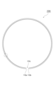
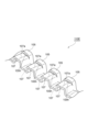
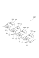
- FIG. 1 is a perspective view of a piston ring according to an embodiment
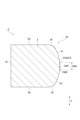
- FIG. FIG. 2 is a cross-sectional view along the line II-II of FIG. 1
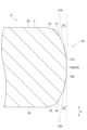
- 3 is an enlarged view of a main part of the cross section of FIG. 2
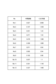
- FIG. 4 is a table illustrating the relationship between the width of the intermediate surface and the wedge angle
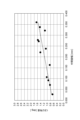
- 5 is a graph illustrating the relationship between the midface width and wedge angle of FIG. 4
- FIG. 3 is a cross-sectional view of a piston ring according to a modification of FIG. 2
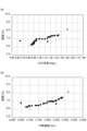
- 4 is a table showing friction measurement results of piston rings according to examples and comparative examples.
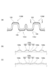
- 8(a) is a graph illustrating the friction measurement results of FIG.
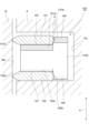
- FIG. 4 is a cross-sectional view schematically showing a state in which an example of a three-piece oil control ring is mounted in a piston groove;
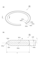
- 11(a) is a perspective view of the side rail of FIG. 10;
- FIG. (b) is a cross-sectional view taken along line bb in (a).
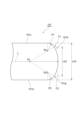
- FIG. 12 is a cross-sectional view showing an enlarged inner peripheral side of the side rail of FIG. 11;
- FIG. 12 is a cross-sectional view showing an enlarged outer peripheral side of the side rail of FIG. 11;
- FIG. 5 is a cross-sectional view showing another example of the inner peripheral surface of the side rail in an enlarged manner;
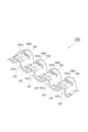
- FIG. 4 is a plan view showing a first example of a spacer expander; 16 is an enlarged perspective view of a region surrounded by a dashed line shown in FIG. 15;
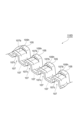
- FIG. 4 is a perspective view partially showing a second example of a spacer expander;
- FIG. 11 is a perspective view partially showing a third example of a spacer expander;
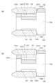
- 19(a) and 19(b) are cross-sectional views of the spacer expander and side rails attached thereto shown in FIG. 18, showing different aspects of the spacer expander.
- FIG. 11 is a perspective view partially showing a fourth example of a spacer expander;
- FIG. 11 is a perspective view partially showing a fifth example of a spacer expander;
- FIG. 11 is a perspective view partially showing a sixth example of a spacer expander;
- (a) is a diagram showing an example of an ear portion having a convex portion on a surface with which an inner peripheral surface of a side rail abuts.
- (b) is a cross-sectional view along line AA in (a) showing a mode in which the convex portion is high.
- (c) is a cross-sectional view taken along line AA in (a), and
- (c) is a cross-sectional view showing a mode in which the convex portion is low.
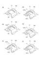
- FIG. 17A is a diagram showing the height H of the ear portion shown in FIG. 16
- FIG. 18B is a diagram showing the height H of the ear portion shown in FIG. 17
- FIG. 19(c) is a diagram showing the height H of the ear portion shown in FIG. 18.
- FIG. 21(d) is a diagram showing the height H of the ear portion shown in FIG. 20.
- FIG. 22(e) is a diagram showing the height H of the ear portion shown in FIG. 21.
- FIG. 23(f) is a diagram showing the height H of the ear portion shown in FIG. 22.
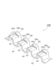
- FIG. 1 is a perspective view of a piston ring according to an embodiment.
- a piston ring 1 shown in FIG. 1 is used, for example, as a second ring provided in a ring groove on the outer peripheral surface of a piston in an internal combustion engine of an automobile. By sliding against the inner wall of the cylinder, the piston ring 1 performs a gas sealing function between the combustion chamber side and the crank chamber side and a function of reducing oil consumption.
- the piston ring 1 has an annular body portion 2 and an abutment portion 3 formed in a part of the body portion 2 .
- the body portion 2 has a pair of side surfaces (one side surface) 2a and side surface (other side surface) 2b, and an inner peripheral surface 2c and an outer peripheral surface 2d.
- the side surfaces 2a and 2b are substantially perpendicular to the inner peripheral surface 2c.
- the width direction of the piston ring 1 is defined as the direction connecting the side surfaces 2a and 2b
- the thickness direction of the piston ring 1 is defined as the direction connecting the inner peripheral surface 2c and the outer peripheral surface 2d.
- the width direction of the piston ring 1 corresponds to the axial direction of the piston ring 1 .
- the main body 2 has a substantially rectangular cross section with long sides in the thickness direction and short sides in the width direction.
- the main body 2 is made of, for example, cast iron or steel containing a plurality of metal elements, and is formed with sufficient strength, heat resistance, and elasticity.
- a hard film may be formed on the surface of the body portion 2 by surface modification.
- the hard film is, for example, a physical vapor deposition film (PVD film) formed using a physical vapor deposition method (PVD method). Thereby, the hard film can be formed with sufficient hardness.
- the hard film is an ion plating film containing at least one of titanium (Ti) and chromium (Cr) and at least one of carbon (C), nitrogen (N) and oxygen, or a diamond-like carbon film.
- the hard film is a titanium nitride film, a chromium nitride film, a titanium carbonitride film, a chromium carbonitride film, a chromium oxynitride film, a chromium film, or a titanium film.
- a chromium nitride film may be used when wear resistance and scuff resistance are emphasized.
- the hard film may be a laminate and may include, for example, a chromium nitride film and a diamond-like carbon film.
- the abutment portion 3 is a part obtained by dividing the main body portion 2, and is formed by a pair of abutment end portions 4 and 5 facing each other.
- the pair of abutment ends 4 and 5 are portions that are free ends of the body portion 2, respectively.
- a gap (abutment gap) of the abutment portion 3 narrows, for example, when the piston ring 1 is heated and thermally expanded.
- the abutment portion 3 functions as a relief portion for thermal expansion of the main body portion 2 caused by the temperature difference between the piston ring 1 and the cylinder.
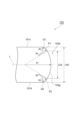
- FIG. 2 is a cross-sectional view along line II-II of FIG.
- the line shape in the following description means the line shape in the cross-sectional view of FIG. 2 unless otherwise specified.
- the outer peripheral surface 2d includes, for example, a first curved surface 21, a second curved surface 22, an intermediate surface 23, a first connection surface 24, and a second connection surface. 25 and are provided.
- the first curved surface 21 is a curved surface convexly curved radially outward of the body portion 2 on the side surface 2a side of the outer peripheral surface 2d.
- the first curved surface 21 extends from the end of the intermediate surface 23 on the side 2a side, which will be described later, toward the side 2a to the end of the first connection surface 24 on the side 2b, which will be described later.
- the first curved surface 21 may extend to the radially outer end of the side surface 2a, for example when the first connecting surface 24 is omitted.
- the first curved surface 21 is curved, for example, in an arc shape.
- the shape of the first curved surface 21 is not limited to this example.
- the shape of the first curved surface 21 may be curved in a shape other than an arc.
- the shape of the first curved surface 21 may partially include straight lines.
- the second curved surface 22 is a curved surface convexly curved radially outward of the body portion 2 on the side surface 2b side of the outer peripheral surface 2d.
- the second curved surface 22 here extends from the end of the intermediate surface 23 on the side surface 2b side toward the side surface 2b to the end of the second connection surface 25 on the side surface 2a side described below.
- the second curved surface 22 may extend to the radially outer end of the side surface 2b, for example when the second connecting surface 25 is omitted.
- the second curved surface 22 is curved, for example, in an arc shape.
- the shape of the second curved surface 22 is not limited to this example.
- the shape of the first curved surface 21 may be curved in a shape other than an arc.
- the shape of the first curved surface 21 may partially include straight lines.
- the first curved surface 21 and the second curved surface 22 are each curved in an arc shape.
- the first curved surface 21 and the second curved surface 22 may be circular arcs that partially overlap a common virtual circle.
- the virtual circle may, for example, have its center located midway between side 2a and side 2b.
- the virtual outermost OM1 which is the outermost part of the virtual circle in the radial direction of the piston ring 1, is located in the center of the width direction (direction) A connecting the side surface 2a and the side surface 2b of the piston ring 1.
- the first curved surface 21 and the second curved surface 22 are part of a symmetrical barrel shape that is symmetrical in the width direction A with respect to the outermost point of the virtual circle.
- the barrel shape means a curved surface that is convexly curved radially outward of the piston ring 1 and includes the radially outermost portion of the piston ring 1 .
- Barrel shapes include symmetric barrel shapes and eccentric barrel shapes.
- the symmetrical barrel shape is a barrel shape, and means a curved surface in which the radially outermost portion of the piston ring 1 is positioned at the center in the width direction A of the outer peripheral surface 2d.
- the eccentric barrel shape is a barrel shape, and means a curved surface in which the radially outermost portion of the piston ring 1 is positioned lower (closer to the crank chamber) than the center in the width direction A of the outer peripheral surface 2d.
- the size of the common virtual circle is defined by the imaginary drop dimension in the radial direction of the piston ring 1 between a point a certain distance away from the imaginary outermost OM1 in the width direction A and the position of the imaginary outermost OM1. can do.
- the points separated from the imaginary outermost portion OM1 by a certain distance in the width direction A may be, for example, one point each separated vertically by 0.25 mm.
- a virtual drop size means a virtual amount of sagging.
- the virtual droop amount may be, for example, 0.001 mm or more and 0.008 mm or less.
- the virtual droop amount may be set according to the width of the intermediate surface 23, which will be described later.
- an intermediate surface 23 is provided between the first curved surface 21 and the second curved surface 22 of the outer peripheral surface 2d.
- the intermediate surface 23 is a contact surface with the inner wall of the cylinder including the portion of the outer peripheral surface 2d that protrudes most radially outward.
- the intermediate surface 23 slides in contact with the inner wall of the cylinder when the piston ring 1 is mounted in the ring groove of the piston.
- the intermediate surface 23 extends along the width direction A so as to connect the first curved surface 21 and the second curved surface 22 .
- the intermediate surface 23 has an upper end connected to the first curved surface 21 and a lower end connected to the second curved surface 22 .
- the intermediate surface 23 here is substantially orthogonal to the side surfaces 2a and 2b and substantially parallel to the inner peripheral surface 2c.
- the intermediate surface 23 extends along the entire circumferential direction of the body portion 2 .
- the width of the intermediate surface 23 along the width direction A is 0.05 mm or more and 0.30 mm or less.
- An intermediate surface width MW along the width direction A may be 0.05 mm or more and 0.25 mm or less.
- An intermediate surface width MW along the width direction A may be 0.05 mm or more and 0.20 mm or less.
- the intermediate surface 23 has a flat portion 23a at least partially.
- the flat portion 23a is a portion of the intermediate surface 23 that is linear in a cross-sectional view perpendicular to the circumferential direction of the body portion 2 .
- the flat portion 23a here is orthogonal to the side surfaces 2a and 2b and parallel to the inner peripheral surface 2c.
- the flat portion 23 a forms a straight line parallel to the axial direction of the piston ring 1 in a cross-sectional view orthogonal to the circumferential direction of the body portion 2 .
- the axial direction of the piston ring 1 corresponds to the width direction A.
- the flat portion 23a is provided along the entire circumferential direction of the piston ring 1 .
- the flat portion 23a has a virtual cylindrical shape as a whole with the abutment portions 3 close to each other.
- the intermediate outermost (outermost) OM2 which is the radially outermost portion of the intermediate surface 23, is the entire flat portion 23a.
- the intermediate outermost OM2 is positioned radially inward of a virtual shape formed by virtually extending the first curved surface 21 and the second curved surface 22 radially outward.
- the intermediate outermost OM2 here is located radially inside the virtual outermost OM1 of the virtual circle described above. Therefore, 2 d of outer peripheral surfaces differ from a general symmetrical barrel shape. On the outer peripheral surface 2d, at the initial stage of use of the new piston ring 1, the degree of point contact (line contact in the circumferential direction) at the top of the curved surface in a cross-sectional view is reduced.
- the outer peripheral surface 2d rather facilitates the formation of a minute wedge shape between the piston ring 1 and the inner wall of the cylinder.
- the flat portion 23a has a flat portion width dimension of 50% or more of the intermediate surface width MW along the width direction A.
- the flat portion width dimension may be 70% or more of the intermediate surface width MW.
- the flat portion width dimension may be 80% or more of the intermediate surface width MW.
- the flat portion 23a here extends linearly parallel to the width direction A over the entire intermediate surface width MW, for example. That is, the flat portion width dimension here is 100%.
- the flat portion width dimension is equal to the intermediate surface width MW along the width direction A and is 0.05 mm or more and 0.30 mm or less.
- the flat portion width dimension may be 0.05 mm or more and 0.25 mm or less.
- the flat portion width dimension may be 0.05 mm or more and 0.20 mm or less.
- the virtual head dimension, intermediate surface width MW, and flat portion width dimension described above can be obtained by measuring the shape of the outer peripheral surface 2d of the piston ring 1 using a commercially available contour shape measuring machine.
- Surfcom 1900DX3 manufactured by ACCRETECH (Tokyo Seimitsu Co., Ltd.), for example, can be used as the contour shape measuring machine.
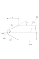
- FIG. 3 is an enlarged view of the main part of the cross section of FIG.
- the wedge angle at both ends of the intermediate surface 23 in the width direction A can be used as an index of the dimension of the intermediate surface width MW.
- the wedge angle is an angle formed by a tangent line to the outer peripheral surface 2 d and the intermediate surface 23 at both ends of the intermediate surface 23 in the width direction A.
- the wedge angle is the angle formed by the first imaginary line 21b contacting the first curved surface 21 and the intermediate surface 23 at the first boundary 21a between the first curved surface 21 and the intermediate surface 23.
- the wedge angle corresponds to the oil introduction angle between the piston ring 1 and the inner wall of the cylinder.
- the wedge angle may be calculated by geometric calculation from the design dimensions.
- the wedge angle may be calculated using the measurement results of the contour measuring machine.
- the dimensions may be calculated by geometric calculation from the dimensions obtained by enlarging the measurement results, or the dimensions on the contour image provided in the contour measuring machine may be calculated using calculation software.
- calculation software it can be calculated from the radius of curvature of the virtual circle and the angle of tangent to the intermediate surface 23 .
- a method for calculating the wedge angle is not particularly limited.
- the intermediate surface 23 is arranged in the central portion of the outer peripheral surface 2d in the width direction A, the central portion of the intermediate surface 23 in the width direction A is positioned in the central portion of the outer peripheral surface 2d.
- the intermediate surface 23 is symmetrical in the width direction A with the central portion of the outer peripheral surface 2d in the width direction A as a boundary. Therefore, the first wedge angle ⁇ 1 and the second wedge angle ⁇ 2 are equal to each other. "Equal to each other” may exclude dimensional differences due to part tolerances and measurement errors. “Equal to each other” may mean geometrically equal to each other.
- FIG. 4 is a table illustrating the relationship between the intermediate face width and the wedge angle.
- FIG. 5 is a graph illustrating the relationship between the midface width of FIG. 4 and the wedge angle.
- FIG. 4 shows a table of wedge angles calculated for piston rings 1 having 12 types of intermediate face widths MW.
- the horizontal axis indicates the intermediate surface width MW
- the vertical axis indicates the wedge angle.
- the wedge angle tends to increase as the intermediate surface width MW increases. Therefore, it can be seen that the wedge angle can be used as an index for the dimension of the intermediate surface width MW.
- the intermediate surface width MW along the width direction A of the piston ring 1 is 0.05 mm or more and 0.30 mm or less. Therefore, according to FIGS. 4 and 5, the wedge angles (first wedge angle ⁇ 1 and second wedge angle ⁇ 2) may be, for example, 0.6 or more and 1.5° or less.
- the wedge angle may be greater than or equal to 0.6 and less than or equal to 1.4°.
- the wedge angle may be greater than or equal to 0.6 and less than or equal to 1.3°.
- the first connection surface 24 is a portion where the corner formed by the side surface 2a and the outer peripheral surface 2d is chamfered.
- the first connecting surface 24 is an inclined surface that connects the side surface 2 a and the first curved surface 21 .
- the first connecting surface 24 extends along the entire circumferential direction of the main body 2 together with the first curved surface 21 .
- the first connection surface 24 is inclined so as to protrude in the radial direction of the body portion 2 from the side surface 2a toward the side surface 2b.
- the first connection surface 24 may smoothly connect the side surface 2a and the first curved surface 21 via a curved surface having an arcuate cross section formed by R processing or the like.
- the first connecting surface 24 may not have a curved surface.
- the first connection surface 24 may be omitted.
- the side surface 2a and the first curved surface 21 may be directly connected.
- the second connection surface 25 is a portion where the corner formed by the side surface 2b and the outer peripheral surface 2d is chamfered.
- the second connection surface 25 is an inclined surface that connects the side surface 2 b and the second curved surface 22 .
- the second connection surface 25 extends along the entire circumferential direction of the body portion 2 together with the second curved surface 22 .
- the second connection surface 25 is inclined so as to protrude in the radial direction of the body portion 2 from the side surface 2b toward the side surface 2a.
- the second connecting surface 25 may smoothly connect the side surface 2b and the second curved surface 22 via a curved surface having an arcuate cross section formed by R processing or the like.
- the second connection surface 25 may not have a curved surface.
- the second connection surface 25 may be omitted.
- the side surface 2b and the second curved surface 22 may be directly connected.
- an intermediate surface 23 having a flat portion 23a at least partially is formed so as to connect the first curved surface 21 and the second curved surface 22 .
- An intermediate surface width MW along the width direction A connecting the side surfaces 2a and 2b is 0.05 mm or more and 0.30 mm or less.
- the intermediate surface 23 having a thickness of 0.05 mm or more and 0.30 mm or less, it is possible to reduce friction loss caused by running-in sliding at the beginning of use of the piston ring 1 . Therefore, a minute wedge-shaped space is easily formed. As a result, it is possible to further reduce friction in the initial stage of use of the piston ring 1 .
- the common virtual circle that defines the arc shapes of the first curved surface 21 and the second curved surface 22 is a part of the symmetrical barrel shape, but it is not limited to this example.
- the shapes of the first curved surface 21 and the second curved surface 22 may be part of a common virtual eccentric barrel shape.
- the shape of the first curved surface 21 and the second curved surface 22 may not be part of the barrel shape.
- the shapes of the first curved surface 21 and the second curved surface 22 may be part of a virtual ellipse.
- the shapes of the first curved surface 21 and the second curved surface 22 should be curved outward in the radial direction of the body portion 2 in a convex shape.
- the intermediate surface 23 is configured as a flat portion 23a extending linearly parallel to the width direction A over the entire intermediate surface width MW, it is not limited to this.
- the flat portion 23a may have a flat portion width dimension along the width direction A that is less than 50% of the intermediate surface width MW.
- the intermediate surface 23 may be linear (tapered) inclined with respect to the width direction A.
- the wedge angle is calculated as an angle substantially formed by the width direction A in which the intermediate surface 23 extends and the tangent line to the outer peripheral surface 2d. It may be calculated as an angle between
- a portion of the intermediate surface 23 other than the flat portion 23a may be a convex portion projecting radially outward.
- a portion of the intermediate surface 23 other than the flat portion 23a may be a groove or recess that is recessed radially inward.
- the protrusions, grooves, or recesses in this case may be curved in a cross-sectional view.
- the protrusions, grooves, or recesses may be formed by a plurality of straight lines in a cross-sectional view.
- first wedge angle ⁇ 1 and the second wedge angle ⁇ 2 were 1.5° or less, the invention is not limited to this example.
- the first wedge angle ⁇ 1 and the second wedge angle ⁇ 2 may be different from each other. Either one of the first wedge angle ⁇ 1 and the second wedge angle ⁇ 2 may be 1.5° or less.
- the side surfaces 2a and 2b are substantially perpendicular to the inner peripheral surface 3c.
- a mode (so-called inner bevel shape) having an inner cut surface 2e that extends obliquely with respect to the direction A may be employed.
- the inner cut surface 2e is a portion of the piston ring 1 where the corner formed by the side surface 2a and the inner peripheral surface 3c is notched.
- the inner cut surface 2 e extends over the entire circumferential direction of the body portion 2 .
- the notch portion may be in the shape of an inner step.
- the torsion angle of the piston ring in a predetermined cylinder mounting state may range from 5' to 90'.
- the predetermined cylinder mounted state corresponds to a state in which the piston is mounted to the cylinder with the piston ring 1A provided in the ring groove of the outer peripheral surface of the piston. With such an inner cut surface 2e, the second boundary 22a comes into strong contact with the inner wall of the cylinder, so the effect of reducing oil consumption due to initial running-in sliding is likely to increase.
- the piston ring according to the above embodiment and modification can be used, for example, as a top ring or a third ring in a diesel engine in addition to the second ring.
- the end face 4a of the abutment end portion 4 and the end face 5a of the abutment end portion 5 exemplify a right angle abutment formed perpendicular to the circumferential direction of the body portion 2.
- the shape of the end portion is not limited to this.
- the end faces 4a and 5a may be inclined abutments formed to be inclined with respect to the circumferential direction.
- the end surfaces 4a and 5a may be stepped joint openings formed so that the side surface 2a side of the end surface 4a and the side surface 2b side of the end surface 5a protrude toward each other.
- a second ring of Example 1 was produced by the following procedure. First, a second ring having a main body having a first curved surface, a second curved surface, and an intermediate surface on the outer peripheral surface was produced.
- a SWOSC-V material was used as a wire rod, and the wire rod was subjected to rolling and drawing.
- the nominal diameter of the main body was set to 73 mm.
- the width of the main body was set to 1.0 mm, and the thickness of the main body was set to 2.1 mm.
- the radius of curvature of the imaginary circle corresponding to the symmetrical barrel shape defining the arcs of the first curved surface and the second curved surface was set to R30.
- the virtual sagging amount of the virtual circle was 0.002 mm or more and 0.006 mm or less.
- the second ring has an inner bevel shape, and the twist angle of the second ring is 5' to 90'.
- a CrN ion plating coating was applied to the surface.
- Surfcom 1900DX3 manufactured by ACCRETECH (Tokyo Seimitsu Co., Ltd.) was used as a contour shape measuring machine to measure the intermediate surface width MW and calculate the wedge angle. Calculation of the wedge angle was performed using calculation software such as dimensions on the contour image provided in the contour shape measuring machine. Friction was measured using the second ring manufactured as described above.
- Friction was measured by attaching a piston with a piston ring set including a second ring to a cylinder, and motoring the piston at an engine speed of 2000 rpm.
- Second rings of Examples 2 to 30 were prepared as shown in FIG. 7 by changing the conditions of the outer peripheral shape of a plurality of second rings manufactured in the same manner, and the intermediate surface width MW was measured, the wedge angle was calculated, and , a friction measurement was performed.
- FIG. 7 is a table showing friction measurement results of piston rings according to Examples and Comparative Examples.
- FIG. 8(a) is a graph illustrating the friction measurement results of FIG. 7 with the horizontal axis representing the wedge angle.
- FIG. 8(b) is a graph illustrating the friction measurement results of FIG. 7, with the horizontal axis representing the intermediate surface width.
- Comparative Example 1 is a piston ring with a tapered outer peripheral surface, and the white circle plotted on the far right indicates Comparative Example 2.
- the black circles plotted to the left of the white circle plots represent Examples 1-30.
- the friction of Comparative Example 1 is as large as 13.5, which is off the scale of the vertical axis.
- the friction of Comparative Example 2 is 8.2, which is smaller than the friction of Comparative Example 1, but the friction is larger than that of the black circle plot group.
- plots with an intermediate surface width MW of 0.078 mm for example, plots with an intermediate surface width MW of 0.078 mm (Example 1), plots of 0.100 mm (Example 5) than plots with an intermediate surface width MW of 0.050 mm (Example 5) 2), and the 0.150 mm plot (Example 3) show less friction.
- Such a tendency that the friction is smaller than that plotted for the intermediate surface width MW of 0.050 mm (Example 5) is seen when the intermediate surface width MW is in the range of 0.050 mm or more and 0.200 mm or less.
- FIG. 9 is a graph illustrating chronological changes in piston ring friction according to the example and the comparative example.
- FIG. 9 when using piston rings with an intermediate face width MW of "none", 0.1 mm, 0.2 mm, and 0.25 mm, respectively, the temporal change in the magnitude of friction with respect to the evaluation time of friction measurement It is shown.
- "No intermediate surface width MW” corresponds to a normal barrel shape in which no intermediate surface is provided on the outer peripheral surface 2d. Note that the origin O in FIG. 9 is the evaluation time 0 (at the start of evaluation).
- the white circle plots without the intermediate surface width MW are compared with the plots with the intermediate surface widths MW of 0.1 mm, 0.2 mm, and 0.25 mm.
- each plot with an intermediate surface width MW of 0.1 mm, 0.2 mm, and 0.25 mm has a small friction magnitude as an initial value compared to the white circle plot without an intermediate surface width MW, and the evaluation time has elapsed. Friction gradually decreases over time.
- the rate of change of the decrease is small compared to the open circle plot without the median plane width MW. From the way friction changes over time, the effect of reducing friction loss due to initial running-in sliding is already obtained at the initial stage of friction (at the start of use of a new piston ring). It is thought that there are It is considered that the provision of the intermediate surface on the outer peripheral surface facilitates the reduction of friction loss compared to the case where the intermediate surface is not provided on the outer peripheral surface.
- the intermediate surface width MW is in the range of 0.050 mm or more and 0.200 mm or less in FIG. It can be said that By back calculating from the fact that there is a reduction in friction loss due to the initial running-in sliding as shown in FIG. can be done. Plots with an intermediate surface width MW of less than 0.050 mm, for example, are presumed to have larger values of friction than plots with an intermediate surface width MW of 0.050 mm, and are presumed to approach the friction values of Comparative Example 2. . Based on this speculation, by providing an intermediate surface on the outer peripheral surface, the intermediate surface width MW is in the range of 0.050 mm or more and 0.300 mm or less, that is, the black circle plot group in FIG. It can be considered that the effect of reducing the loss is obtained.
- FIG. 10 is a cross-sectional view schematically showing a state in which an example of a three-piece oil control ring is mounted in the groove Pa of the piston P. As shown in FIG. This cross-sectional view shows a cross-section in the axial direction of the oil control ring (reciprocating direction A of the piston P). The reciprocating direction A may be the same direction as the width direction A.
- the oil control ring 150 includes a pair of side rails 101, 102 and a spacer expander 110A arranged between the pair of side rails 101, 102.
- the outer peripheral surfaces 101a, 102a of the side rails 101, 102 are in contact with the inner surface Ba of the cylinder bore B.
- the inner peripheral surfaces 101b, 102b of the side rails 101, 102 are in contact with the ears 105 of the spacer expander 110A.
- the side rails 101 and 102 are made of, for example, stainless steel or carbon steel.
- the side rails 101, 102 may have hard coatings (not shown) provided to cover at least the outer peripheral surfaces 101a, 102a.
- hard coating materials include amorphous carbon, chromium nitride (CrN), titanium nitride (TiN), titanium carbide (TiC), aluminum titanium nitride (TiAlN), chromium nitride (CrN), TiCN, AlCrN, TiC, Alternatively, nickel alloys such as nickel (Ni) and nickel phosphorous (NiP) can be used.
- side rails 101 and 102 have the same shape. The shape of the side rail 101 will be described below, and the description of the shape of the side rail 102 will be omitted.
- FIG. 11(a) is a perspective view of the side rail 101
- FIG. 11(b) is a cross-sectional view taken along line bb shown in FIG. 11(a).
- the side rail 101 has a vertically symmetrical shape in an axial cross section about a center line L indicated by a dashed line in FIG. 11(b).
- the side rail 101 includes an outer peripheral surface 101a, an inner peripheral surface 101b, first and second side surfaces 101c and 101d, a first inclined surface 101e between the outer peripheral surface 101a and the first side surface 101c, and an outer peripheral surface. 101a and a second inclined surface 101f between the second side surfaces 101d.
- FIG. 11(b) is a perspective view of the side rail 101
- FIG. 11(b) is a cross-sectional view taken along line bb shown in FIG. 11(a).
- the side rail 101 has a vertically symmetrical shape in an axial cross section about a center line L indicated by a dashed line in FIG. 11(
- the center of gravity G of the side rail 101 is on the center line L and located closer to the inner peripheral surface 101b than the center position of the side rail 101 in the thickness direction.
- the inner peripheral surface 101b has a vertically symmetrical shape in an axial cross section.
- the outer peripheral surface 101a, the first inclined surface 101e, and the second inclined surface 101f (surfaces on the outer peripheral side of the side rail 101) have vertically symmetrical shapes in an axial cross section.
- the cross-sectional shape of the outer peripheral side of the side rail 101 is not limited to this example, and may have a vertically asymmetric shape in the cross section in the axial direction.
- the outer peripheral surface 101a may have a cross-sectional shape in which the center line L is biased toward one of the first and second side surfaces 101c and 101d.
- the side rail 101 is annular, and has an outer diameter of 60 to 120 mm and an inner diameter of 56 to 114 mm, for example.
- the height Lh0 of the side rail 101 is, for example, 0.2-0.7 mm, and may be 0.25-0.55 mm or 0.30-0.45 mm. It should be noted that the term "annular" as used herein does not necessarily mean a closed circle, and the side rail 101 may have an abutment.
- the side rail 101 may be perfectly circular or elliptical in plan view.
- the contour shape (shape of the inner peripheral surface, the outer peripheral surface, etc.) of the side rail can be measured using a contour shape measuring machine (for example, manufactured by ACCRETECH (Tokyo Seimitsu Co., Ltd.)).
- FIG. 12 is a sectional view showing an enlarged inner peripheral side of the side rail 101.
- the inner peripheral surface 101b of the side rail 101 has an inner tip portion 101g located at the center portion in the height direction of the side rail 101 in an axial cross section.
- the inner tip portion 101g satisfies the following condition A1.
- Condition A1 0.7 ⁇ R1/Lh0 ⁇ 1.1
- R1 indicates the radius of curvature (unit: mm) of the curve forming the inner tip portion 101g
- Lh0 indicates the height (unit: mm) of the side rail.
- the ratio Lh2/Lh0 of the height Lh2 of the inner tip portion 101g to the height Lh0 of the side rail 101 may be 1 or less.
- the ratio Lh2/Lh0 may be between 0.5 and 0.75.
- the ratio Lh2/Lh0 may be between 0.5 and 0.7.
- the ratio Lh2/Lh0 may be between 0.5 and 0.65.
- the height Lh2 means the distance from one inflection point (apex of the convex curved portion C1) to the other inflection point (apex of the convex curved portion C2) in an axial cross section (see FIG. 12). ).
- the inner peripheral surface 101b may further include peripheral edge portions P1 and P2 located so as to sandwich the inner tip portion 101g.
- the inner tip portion 101g and the peripheral portion P1 may form the convex curved portion C1, and the inner tip portion 101g and the peripheral portion P2 may form the convex curved portion C2.
- the peripheral portions P1 and P2 may satisfy the following condition A2.
- Condition A2 0.2 ⁇ R2/Lh0 ⁇ 0.5
- R2 indicates the radius of curvature (unit: mm) of the curves forming the peripheral portions P1 and P2
- Lh0 indicates the height of the side rail (unit: mm).
- FIG. 13 is a cross-sectional view showing an enlarged outer peripheral side of the side rail 101.
- the outer peripheral surface 101a of the side rail 101 may have an outer tip portion 101h that satisfies the following condition A3 in an axial cross section.
- Condition A3 0.1 ⁇ R0/Lh0 ⁇ 0.23
- R0 indicates the curvature radius (unit: mm) of the curve forming the outer tip portion 101h
- Lh0 indicates the height of the side rail 101 (unit: mm).
- the angle ⁇ of the first and second inclined surfaces 101e and 101f may be 30-50°.
- the angle .theta. means an angle formed by a plane perpendicular to the axial direction and the inclined planes 101e and 101f.
- the radial distance a (unit: mm) from the tip of the outer peripheral surface 101a to the boundary between the side surface 101c and the inclined surface 101e may satisfy the following condition A4.
- T indicates the thickness (unit: mm) of the side rail 101 in the axial cross section (see FIG. 11(b)).
- the inner tip portion of the inner peripheral surface satisfies the condition A1
- the behavior of the side rail is affected by the frictional force with the cylinder and the inertial force associated with the reciprocating motion. Since increasing the speed of reciprocating motion increases the inertial force applied to the oil control ring, it is presumed that the effect of inertial force is more dominant than the effect of frictional force.
- the center of gravity is shifted to the inner peripheral surface side and the contact position with the ear of the spacer expander is shifted as compared with the conventional side rail. It is presumed that these matters contribute to the stabilization of the behavior of the side rails. That is, according to the side rail 101 and the oil control ring using the side rail 101 as described above, it is possible to sufficiently suppress an increase in oil consumption even when the internal combustion engine is operating at a high rotational speed. .
- the siderails of the present disclosure are not limited to the siderails 101 described above.
- the inner peripheral surface of the side rail 101 is formed of two arcs having different radii of curvature in the cross section in the axial direction. It may be composed of three or more circular arcs having different radii of curvature in the cross section.
- the side rail 103 shown in FIG. 14 is composed of three arcs with different radii of curvature.
- the inner peripheral surface 103b of the side rail 103 is formed on the inner tip portion 103g with the curvature radius R1, the first peripheral edge portions P1 and P2 with the curvature radius R2 formed so as to sandwich the inner tip portion 103g, and on the outside thereof. and second peripheral edge portions Q1 and Q2 having a radius of curvature R3.
- the inner peripheral surface 103b may satisfy the following conditions A1a to A3a.
- Lh0 indicates the height of the side rail 103
- Lh2 indicates the height of the inner tip portion (portion with curvature radius R1) (height Lh2 in FIG. 14).
- Condition A1a 0.7 ⁇ R1/Lh0 ⁇ 1.1
- Condition A2a 0.2 ⁇ R2/Lh0 ⁇ 0.5
- Condition A3a Lh2/Lh0 ⁇ 1.0
- the value of the ratio Lh2/Lh0 related to condition A3a may be 0.5 to 0.75.
- the value of the ratio Lh2/Lh0 may be between 0.5 and 0.7.
- the value of the ratio Lh2/Lh0 may be between 0.5 and 0.65.
- Lh2 means the height of the inner tip portion 103g (the distance from one inflection point to the other inflection point) in the axial cross section.
- an oil control ring composed of the piston ring 1, the side rail 101, and a spacer expander disposed between the pair of side rails.
- an oil control ring composed of the piston ring 1, the side rail 101, and a spacer expander disposed between the pair of side rails.
- the piston ring 1 promotes reduction of friction loss due to initial running-in sliding when the piston ring 1 is started to be used. Therefore, a minute wedge-shaped space is easily formed. As a result, it is possible to further reduce friction in the initial stage of use of the piston ring 1 .
- the side rail 101 can sufficiently suppress an increase in oil consumption even when the internal combustion engine is operating at a high rotational speed.
- the extent to which the piston ring 1 is responsible for the oil consumption can be suppressed. 1 can be configured to further reduce the friction at the initial stage of use of the piston ring 1 .
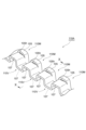
- FIG. 15 is a plan view of a first example of a spacer expander.
- the spacer expander 110A is annular and has an abutment 110c formed by two end faces 110a and 110b.
- the spacer expander 110A is manufactured, for example, by pressing (cutting, bending and punching) a steel plate, or by plastically deforming a wire made of spring steel while meshing it with a plurality of gears.
- the spacer expander 110A may be subjected to surface treatment from the viewpoint of improving wear resistance, adhesion resistance, and the like.
- electroless and electrolytic plating may be used to form a film on the surface of spacer expander 110A.
- Film materials include amorphous carbon film, chromium nitride film (CrN), titanium nitride film (TiN), titanium carbide (TiC), aluminum titanium nitride (TiAlN), chromium nitride (CrN), TiCN, AlCrN, and TiC.
- a polymer film such as polyimide may be formed instead of the inorganic material film. It should be noted that the polymer film may contain a filler such as carbon fiber or glass fiber.
- FIG. 16 is a perspective view showing an enlarged area surrounded by a dashed line shown in FIG.
- the oil control ring 150 includes a pair of side rails 101, 102 and a spacer expander 110A arranged between the pair of side rails 101, 102.
- the outer peripheral portions of the side rails 101 and 102 are in contact with the inner surface Ba of the cylinder bore B.
- the thickness of the portion indicated by hatching in FIG. 10 is, for example, 0.1 mm to 0.7 mm.
- this portion By making this portion as thick as possible, a higher tension can be obtained and a contact area with the side rails 101 and 102 can be ensured, so a more excellent wear reduction effect can be obtained. It is also possible to increase the rigidity of each portion of the spacer expander 110A, which will be described later.
- As the side rails 101 and 102 conventionally known ones can be used.
- the shape of the outer peripheral surface and the shape of the inner peripheral surface of the side rail may be different from those of the side rails 101 and 102.
- the cross-sectional shape may not necessarily have symmetry.
- the spacer expander 110A has a plurality of ear portions 105 with which the inner peripheral surfaces 101b and 102b of the side rails 101 and 102 abut, and a plurality of rail facing portions 107 which face the side surfaces 101d and 102c of the side rails 101 and 102, respectively. have The rail facing portion 107 is formed on the outer peripheral side of the ear portion 105 and adjacent to the ear portion 105 .
- the inner peripheral surfaces 101b and 102b of the side rails 101 and 102 are in contact with the ear portions 105, and the rail facing portions 107 and the side surfaces 101d of the side rails 101 and 102 are in contact with each other.
- 102c face each other, the ear portion 105 is formed higher than the rail facing portion 107.
- the spacer expander 110A has an opening 105h formed by the ear portion 105 and the rail facing portion 107. As shown in FIG.
- the surfaces of the ear portions 105 with which the side rails 101 and 102 abut are inclined with respect to the axial direction.
- the tilt angle ⁇ shown in FIG. 10 may be between 5 and 30 degrees.
- the tilt angle ⁇ may be 10-25°.
- the spacer expander 110A has, for example, a shape in which peaks 110M and valleys 110V are alternately connected when placed on a workbench.
- the ear portion 105 positioned at the peak portion 110M (upper side in FIG. 16) of the spacer expander 110A and the ear portion 105 positioned at the valley portion 110V (lower side in FIG. 16) have substantially the same shape.
- the rail facing portion 107 positioned at the peak portion 110M (upper side in FIG. 16) of the spacer expander 110A and the rail facing portion 107 positioned at the valley portion 110V (lower side in FIG. 16) have substantially the same shape. Therefore, if the spacer expander 110A placed on the workbench is turned upside down, the peaks 110M shown in FIG. 16 become the valleys 110V, and the valleys 110V become the peaks 110M.
- the ear portions 105 and the rail-facing portions 107 located in the peak portions 110M of the spacer expander 110A will be described below, and the description of the ear portions 105 and the rail-facing portions 107 located in the valley portions 110V will be omitted. It should be noted that the following description of heights such as "the highest position" of the ear portion 105 and the rail-facing portion 107 refers to the height of the ear portion 105 of the upper mountain portion 110M when the spacer expander 110A is placed on a workbench. and the rail facing portion 107.
- the ear portion 105 and the rail-facing portion 107 of the valley portion 110V located on the lower side should be called, for example, the “lowest position” of the ear portion 105 and the rail-facing portion 107.
- the valley portion 110V becomes the peak portion 110M. It is also applied to the facing portion 107 .
- the ear portion 105 is a portion with which the inner peripheral surface 101b of the side rail 101 abuts.
- the shape of the ear portion 105 may satisfy condition B1 represented by inequality (1).
- the shape of the ear portion 105 may satisfy condition B2 expressed by inequality (2).
- Condition B2: W/H ⁇ 1.7 (2) W indicates the width (unit: mm) of the ear portion 105 at a position moved 0.05 mm from the highest position of the ear portion 105 toward the rail facing portion 107 (thickness direction of the spacer expander 110A) (Fig.
- H indicates the height difference (unit: mm) between the highest position of the region adjacent to the ear portion in the rail facing portion 107 and the highest position of the ear portion (see FIG. 25(a)).
- the position moved 0.05 mm in the direction of the rail facing portion 107 from the highest position of the ear portion 105 is the oil control This is because it is presumed that the side rails 101 and 102 frequently come into contact with the corresponding position of the ear portion 105 in the early stage of use of the ring 150 .
- the ears 105 with a W/H value of 1.5 or more can suppress the amount of wear due to contact with the side rails 101 compared to those with a W/H value of less than 1.5.
- the upper limit of the value of W/H is, for example, 5.0 from the viewpoint of tension generated from the spacer expander 110A.
- the top of ear 105 may have a flat portion.
- the top of ear 105 may not have a flat portion. That is, the shape of the side surface of the ear portion 105 may be formed from a continuous curved surface, in other words, the side surface shape of the ear portion 105 may be a shape in which curved surfaces with different curvatures are continuous.
- the spacer expander can be easily manufactured, and can be formed into a shape in which stress concentration is less likely to occur during plastic deformation. Therefore, it is possible to reduce the occurrence of breakage or the like.
- the height H of the ear portion 105 may be 0.2-0.75.
- the width W is, for example, 1.0-1.8 mm
- the height H may be 0.2-0.65 mm.
- the width W is, for example, 1.3-1.8 mm
- the height H may be 0.35-0.7 mm.
- the height of the ears is suppressed compared to the width of the ears.
- the mechanical strength of the ears of the spacer expander 110A can be increased. Therefore, even if the spacer expander 110A receives an external force due to the reciprocating motion of the piston, the tension of the spacer expander 110A can be stably transmitted to the side rails 101, 102 and supported by the spacer expander 110A.
- the attitude of the side rails 101 and 102 that are attached to the side rails 101 and 102 can be maintained in a stable state. As a result, the oil scraping performance of the side rails 101 and 102 is stabilized, and as a result, the oil consumption is also stabilized.
- the spacer expander 110A is obtained by plastically deforming a plate material or a wire material
- the spacer expander 110A increases, the volume to be changed in shape by plastic deformation increases. Additionally, since ears 105 have a reduced height relative to their width, such manufacturing difficulties are less than in conventional spacer expanders.
- the height H of the ear portion 105 is the height difference between the highest position of the region adjacent to the ear portion 105 in the rail facing portion 107 and the highest position of the ear portion 105 .
- the search range for the “highest position” in the rail facing portion 107 is within the region of the rail facing portion 107 adjacent to the ear portion 105 .
- FIG. 25(a) shows the height difference (height H of ear 105) between the highest position of the region adjacent to ear 105 in rail facing portion 107 of spacer expander 110A and the highest position of ear 105.
- FIG. It shows how to find it.
- 25(b) to 25(f) show how to obtain the height H of the ear portion 105 of the spacer expander, which will be described later.
- a straight line passing through the highest position of the ear portion 105 is indicated by h2
- a straight line passing through the highest position of the area adjacent to the ear portion in the rail facing portion 107 is indicated by h1.
- Both the straight lines h1 and h2 are straight lines parallel to the tangential direction of the spacer expander 110A at each crest.
- the rail facing portion 107 when a convex portion (flat portion 107c) that abuts on the side rail side surface is provided at the outer peripheral end away from the ear portion 105, the rail facing portion 107, in the region other than the convex portion Find the highest position.
- the method of searching for the highest position of the rail facing portion 107 is based on an envelope curve connecting the highest positions of the respective ear portions 105 of the plurality of crests with approximately straight lines. In the area adjacent to , the position closest to the envelope is the highest position.
- the rail facing portion 107 is composed of a flat surface as shown in FIG.
- the side rails 101 and 102 abut against the flat surface, thereby supporting the side rails 101 and 102.
- the spacer expander 110B has the same configuration as the spacer expander 110A, except that the rail facing portion 107 has a raised portion 107b extending radially instead of the flat surface (see FIG. 1). 17). Since the rail facing portion 107 has the protruding portion 107b, it is possible to sufficiently prevent engine oil and foreign matter contained therein from accumulating on the surface of the rail facing portion 107, and the rail facing portion 107 and the side rail 101 are fixed. can be sufficiently suppressed.
- the protuberance 107b extends to the outer edge of the spacer expander 110B.
- the spacer expander 110C has a flat portion 107c on the outer peripheral side instead of the rail facing portion 107 having a flat surface, and a recess extending radially between the ear portion 105 and the flat portion 107c. It has the same configuration as the spacer expander 110A except that it has 107a (see FIG. 18). By adopting such a configuration, retention of combustion products such as sludge between the rail facing portion 107 and the side rails 101 and 102 can be prevented. It also contributes to the suppression of sticking.
- the depth of the depression 107a (height difference between the highest position of the rail facing portion 107 and the lowest position of the depression 107a) is, for example, 50 to 500 ⁇ m.
- the flat portion 107c is formed along the outer edge of the spacer expander 110C. By forming the height of the flat portion 107c to be lower than the ear portion 105 and higher than the other portion of the rail facing portion 107, the rail facing portion 107 can be flattened when the side rail 101 is in contact with the flat portion 107c. A gap is formed between the portion and the side rail 101 .
- the flat portion 107c is also referred to as a "protrusion", and the area of the rail facing portion 107 other than the flat portion 107c (the portion connecting the ear portion 105 and the flat portion 107c) is also referred to as a "middle portion".
- the rail facing portion 107 has the flat portion 107c, a space is formed between the side surfaces 101d and 102c of the side rails 101 and 102 and the spacer expander 110C, and the oil scraped off from the cylinder bore by the side rails 101 and 102 is removed. is scraped off between the ear portion 105 and the rail facing portion 107, and effectively flows to the inner peripheral side of the spacer expander 110C.
- FIGS. 19(a) and 19(b) are cross-sectional views of the spacer expander 110C shown in FIG. 18 and the side rails 101 and 102 attached thereto, showing different modes.
- the rail facing portion 107 has a step between the flat portion 107c and the other region 7d (middle portion).
- the portion between the flat portion 107c and the other region 7d in the rail facing portion 107 is not cut, and the member is continuous. In other words, no through hole is formed in this portion.
- the rail facing portion 107 is cut between the flat portion 107c and the other region 7d, and a through hole 7h is formed in this portion.
- the through hole 7h may or may not be formed, but when used in an environment where foreign matter is likely to exist, such as in a diesel engine, the through hole 7h may be blocked by the foreign matter. , the provision of the through hole 7h may increase the degree of deterioration of the tension over time. If there are these concerns due to the environment of the internal combustion engine, a spacer expander without through holes 7h may be used as shown in FIG. 19(a). On the other hand, the provision of the through holes 7h increases the chances that the oil scraped off from the cylinder bores can efficiently flow to the inner peripheral side of the spacer expander 110C.
- the through hole 7h may be formed by, for example, the deepest portion of the recess 107a and the flat portion 107c.
- the center of gravity G of the side rails 101 and 102 may be located inside the flat portion 107c.
- the spacer expander 110D has a flat portion 107c on the outer peripheral side instead of the rail facing portion 107 having a flat surface, and a raised portion extending radially between the ear portion 105 and the flat portion 107c. It has the same configuration as the spacer expander 110A except that it has 107b (see FIG. 20). The flat portion 107c is formed along the outer edge of the spacer expander 110D.
- the spacer expander 110E has the same configuration as the spacer expander 110A except that the rail facing portion 107 has a recess 107a extending in the radial direction instead of the rail facing portion 107 having a flat surface (see FIG. 21). ).
- the depression 107a extends to the outer edge of the spacer expander 110E.
- the spacer expander 110E having such a configuration has the advantage of being easier to process by plastic deformation than the spacer expander described above.
- the spacer expander 110F has a configuration similar to that of the spacer expander 110A, except that the rail facing portion 107 has a flat portion 107c on the outer peripheral side instead of the flat surface (see FIG. 22).
- the spacer expander 110F having such a configuration has the advantage of being easily processed by plastic deformation, like the spacer expander of the sixth example described above.
- the surface of the ear portion 105 with which the inner peripheral surface 101b of the side rail 101 abuts was exemplified. may have a plurality of protrusions 105b extending in the thickness direction (the height direction of the ears 105). These convex portions 105b may be formed so as to be aligned in the width direction of the ear portion 105. As shown in FIG.
- FIG. 23(a) is a view of the spacer expander viewed from the outer peripheral side.
- An ear portion 105 and the ear portion 105 of the valley portion 110V that presses the other side rail 102 are formed.
- the ear portion 105 is formed with a circumferentially uneven portion in which the concave portion and the convex portion extend substantially in the axial direction. By reducing the contact area of the convex surface and increasing the contact surface pressure, it is possible to prevent the side rails from rotating independently.
- 23(b) and 23(c) are cross-sectional views taken along the line AA in FIG. 23(a), FIG. is a cross-sectional view showing a mode in which the convex portion is low.
- the convex portion 105b is formed so as to protrude from the concave surface 161, and consists of a convex surface 162 and side surfaces 163 connecting the convex surface 162 and the concave surface 161 together.
- At least five (for example, seven) protrusions 105 b may be formed in one ear portion 105 so as to be aligned in the width direction of the ear portion 105 .
- the convex portion 105b is formed, for example, by forming a concave portion by cutting between two adjacent convex portions 105b.
- each of the above examples assumes that all ear portions 105 and rail facing portions 107 have substantially the same shape, they do not necessarily have to have substantially the same shape.
- none of the ears 105 do not have to satisfy the condition expressed by inequality (1) or (2).
- at least half of the plurality of ear portions 105 formed on one surface may satisfy the condition expressed by inequality (1) or (2).
- spacer expanders having ears with a W/H value of 1.5 or more have lower ear lengths than those with a W/H value of less than 1.5. It was found that the amount of wear can be suppressed. Since the dimensional ratio is such that the height of the ear portion is limited to the width of the ear portion, the strength and workability of the ear portion are improved.
- the upper limit of the value of W/H is, for example, 5.0 from the viewpoint of the tension generated by the spacer expander. That is, according to the spacer expanders 110A to 110F and the oil control ring using the spacer expanders 110A to 110F as described above, it is possible to suppress wear of the ears due to contact with the side rails.
- the oil control ring according to the present disclosure can sufficiently suppress wear of the ears, and is therefore applicable to diesel engines.
- the conventional three-piece oil control ring is widely applied to gasoline engines, it is generally not applied to diesel engines because the wear resistance of the ears is insufficient. This is because diesel engines are lubricated with a large amount of hard particles such as carbon generated during combustion in the engine oil.
- the panda's ears also wear out relatively quickly, and the oil scraping performance tends to decline.
- a piston ring set comprising the piston ring 1, the spacer expanders 110A to 110F, and an oil control ring to which the spacer expanders 110A to 110F are applied is constructed. be able to.
- the piston ring 1 promotes reduction of friction loss due to initial running-in sliding when the piston ring 1 is started to be used. Therefore, a minute wedge-shaped space is easily formed. As a result, it is possible to further reduce friction in the initial stage of use of the piston ring 1 .
- the spacer expanders 110A to 110F suppress wear of the ears due to contact with the side rails, thereby suppressing deterioration in oil scraping performance. Therefore, for example, it is possible to suppress the extent to which the piston ring 1 is responsible for suppressing the deterioration of the oil scraping performance over the medium to long term, and the piston ring 1 can be further reduced in friction at the beginning of the use of the piston ring 1. It becomes possible to set it as the target structure.
Landscapes
- Engineering & Computer Science (AREA)
- General Engineering & Computer Science (AREA)
- Mechanical Engineering (AREA)
- Chemical & Material Sciences (AREA)
- Combustion & Propulsion (AREA)
- Pistons, Piston Rings, And Cylinders (AREA)
Priority Applications (4)
| Application Number | Priority Date | Filing Date | Title |
|---|---|---|---|
| KR1020247023693A KR20240121849A (ko) | 2021-12-28 | 2022-12-20 | 피스톤 링 및 피스톤 링 세트 |
| EP22915831.6A EP4435298A4 (en) | 2021-12-28 | 2022-12-20 | PISTON RING AND PISTON RING ASSEMBLY |
| CN202280084590.3A CN118369529A (zh) | 2021-12-28 | 2022-12-20 | 活塞环及活塞环组 |
| US18/721,195 US20250052320A1 (en) | 2021-12-28 | 2022-12-20 | Piston ring and piston ring set |
Applications Claiming Priority (2)
| Application Number | Priority Date | Filing Date | Title |
|---|---|---|---|
| JP2021-214413 | 2021-12-28 | ||
| JP2021214413A JP7579237B2 (ja) | 2021-12-28 | 2021-12-28 | ピストンリング及びピストンリングセット |
Publications (1)
| Publication Number | Publication Date |
|---|---|
| WO2023127607A1 true WO2023127607A1 (ja) | 2023-07-06 |
Family
ID=86998904
Family Applications (1)
| Application Number | Title | Priority Date | Filing Date |
|---|---|---|---|
| PCT/JP2022/046957 Ceased WO2023127607A1 (ja) | 2021-12-28 | 2022-12-20 | ピストンリング及びピストンリングセット |
Country Status (6)
| Country | Link |
|---|---|
| US (1) | US20250052320A1 (enExample) |
| EP (1) | EP4435298A4 (enExample) |
| JP (1) | JP7579237B2 (enExample) |
| KR (1) | KR20240121849A (enExample) |
| CN (1) | CN118369529A (enExample) |
| WO (1) | WO2023127607A1 (enExample) |
Families Citing this family (2)
| Publication number | Priority date | Publication date | Assignee | Title |
|---|---|---|---|---|
| JP7467783B1 (ja) | 2024-02-05 | 2024-04-15 | トクセン工業株式会社 | 圧力リング用線 |
| JP7508717B1 (ja) | 2024-02-05 | 2024-07-01 | トクセン工業株式会社 | 圧力リング用線 |
Citations (11)
| Publication number | Priority date | Publication date | Assignee | Title |
|---|---|---|---|---|
| JPS53150308U (enExample) * | 1977-04-30 | 1978-11-27 | ||
| JPS648553U (enExample) * | 1987-07-03 | 1989-01-18 | ||
| JPH0514733U (ja) * | 1991-08-12 | 1993-02-26 | 株式会社リケン | ピストンリング |
| JPH0611038A (ja) | 1992-06-22 | 1994-01-21 | Riken Corp | 内燃機関用ピストンリング |
| JP2002323133A (ja) * | 2001-02-23 | 2002-11-08 | Teikoku Piston Ring Co Ltd | 圧力リング用線材及び圧力リングとその製造方法 |
| JP2006336744A (ja) * | 2005-06-01 | 2006-12-14 | Toyota Motor Corp | ピストンリング |
| JP4165119B2 (ja) * | 2002-05-15 | 2008-10-15 | 日産自動車株式会社 | 内燃機関のピストンリング |
| JP2017026054A (ja) * | 2015-07-23 | 2017-02-02 | 株式会社リケン | ピストンリング |
| WO2019194104A1 (ja) * | 2018-04-06 | 2019-10-10 | 株式会社リケン | スペーサエキスパンダ及びこれを備えるオイルコントロールリング |
| JP2021001612A (ja) * | 2019-06-19 | 2021-01-07 | Tpr株式会社 | ピストンリングの組み合わせ |
| WO2022209592A1 (ja) * | 2021-03-31 | 2022-10-06 | 株式会社リケン | サイドレール及びこれを備えるオイルコントロールリング |
Family Cites Families (14)
| Publication number | Priority date | Publication date | Assignee | Title |
|---|---|---|---|---|
| BR8802641A (pt) * | 1988-05-26 | 1990-01-09 | Cofap | Segmento de anel para motores de combustao interna |
| DE4429649C2 (de) * | 1994-08-20 | 1998-02-19 | Ae Goetze Gmbh | Kolbenring |
| JP4132815B2 (ja) * | 2001-12-28 | 2008-08-13 | 株式会社リケン | サイドレール及び組合せオイルリング |
| JP4322500B2 (ja) * | 2002-12-18 | 2009-09-02 | 帝国ピストンリング株式会社 | 組合せオイルリング |
| JP2010031835A (ja) * | 2008-06-23 | 2010-02-12 | Nissan Motor Co Ltd | 内燃機関用オイルリング及びピストン |
| JP6239964B2 (ja) * | 2013-12-18 | 2017-11-29 | 株式会社リケン | 組合せオイルコントロールリング |
| US9784369B2 (en) * | 2014-09-12 | 2017-10-10 | Tpr Co., Ltd. | Combination oil ring |
| JP6530200B2 (ja) * | 2015-02-23 | 2019-06-12 | 株式会社リケン | サイドレール |
| JP6533670B2 (ja) * | 2015-03-12 | 2019-06-19 | 株式会社リケン | サイドレール |
| CN109416124B (zh) * | 2017-07-05 | 2020-04-14 | 帝伯爱尔株式会社 | 组合油环 |
| JP6603284B2 (ja) * | 2017-10-05 | 2019-11-06 | 株式会社リケン | サイドレール |
| JP6400874B1 (ja) * | 2018-05-21 | 2018-10-03 | Tpr株式会社 | 組合せオイルリング |
| EP3825584B1 (en) * | 2018-11-15 | 2024-08-07 | Tpr Co., Ltd. | Piston ring combination |
| JP2021060048A (ja) * | 2019-10-03 | 2021-04-15 | 日本ピストンリング株式会社 | 内燃機関の摺動構造、内燃機関の摺動構造の作り込み方法 |
-
2021
- 2021-12-28 JP JP2021214413A patent/JP7579237B2/ja active Active
-
2022
- 2022-12-20 CN CN202280084590.3A patent/CN118369529A/zh active Pending
- 2022-12-20 US US18/721,195 patent/US20250052320A1/en active Pending
- 2022-12-20 EP EP22915831.6A patent/EP4435298A4/en active Pending
- 2022-12-20 KR KR1020247023693A patent/KR20240121849A/ko active Pending
- 2022-12-20 WO PCT/JP2022/046957 patent/WO2023127607A1/ja not_active Ceased
Patent Citations (11)
| Publication number | Priority date | Publication date | Assignee | Title |
|---|---|---|---|---|
| JPS53150308U (enExample) * | 1977-04-30 | 1978-11-27 | ||
| JPS648553U (enExample) * | 1987-07-03 | 1989-01-18 | ||
| JPH0514733U (ja) * | 1991-08-12 | 1993-02-26 | 株式会社リケン | ピストンリング |
| JPH0611038A (ja) | 1992-06-22 | 1994-01-21 | Riken Corp | 内燃機関用ピストンリング |
| JP2002323133A (ja) * | 2001-02-23 | 2002-11-08 | Teikoku Piston Ring Co Ltd | 圧力リング用線材及び圧力リングとその製造方法 |
| JP4165119B2 (ja) * | 2002-05-15 | 2008-10-15 | 日産自動車株式会社 | 内燃機関のピストンリング |
| JP2006336744A (ja) * | 2005-06-01 | 2006-12-14 | Toyota Motor Corp | ピストンリング |
| JP2017026054A (ja) * | 2015-07-23 | 2017-02-02 | 株式会社リケン | ピストンリング |
| WO2019194104A1 (ja) * | 2018-04-06 | 2019-10-10 | 株式会社リケン | スペーサエキスパンダ及びこれを備えるオイルコントロールリング |
| JP2021001612A (ja) * | 2019-06-19 | 2021-01-07 | Tpr株式会社 | ピストンリングの組み合わせ |
| WO2022209592A1 (ja) * | 2021-03-31 | 2022-10-06 | 株式会社リケン | サイドレール及びこれを備えるオイルコントロールリング |
Non-Patent Citations (1)
| Title |
|---|
| See also references of EP4435298A4 |
Also Published As
| Publication number | Publication date |
|---|---|
| US20250052320A1 (en) | 2025-02-13 |
| EP4435298A1 (en) | 2024-09-25 |
| JP2023097976A (ja) | 2023-07-10 |
| KR20240121849A (ko) | 2024-08-09 |
| JP7579237B2 (ja) | 2024-11-07 |
| EP4435298A4 (en) | 2025-10-22 |
| CN118369529A (zh) | 2024-07-19 |
Similar Documents
| Publication | Publication Date | Title |
|---|---|---|
| CN105849444B (zh) | 组合油环 | |
| JP7579237B2 (ja) | ピストンリング及びピストンリングセット | |
| US10352445B2 (en) | Piston ring | |
| JP7254836B2 (ja) | 組合せオイルリング | |
| JP7116861B1 (ja) | サイドレール及びこれを備えるオイルコントロールリング | |
| JP6836690B2 (ja) | スペーサエキスパンダ及びこれを備えるオイルコントロールリング | |
| JP6817374B2 (ja) | ピストンリング | |
| JP6603284B2 (ja) | サイドレール | |
| JP7339456B1 (ja) | オイルコントロールリング | |
| JP7529709B2 (ja) | オイルリング | |
| JP7284308B1 (ja) | ピストンリング | |
| JP6491286B2 (ja) | オイルリング | |
| WO2024161511A1 (ja) | 摺動機構 | |
| JP6914291B2 (ja) | 内燃機関のシリンダ | |
| JP2024109044A (ja) | 摺動機構 | |
| WO2025169528A1 (ja) | 水素燃料を使用する内燃機関用のピストンリングセット並びにピストンリング、及び水素燃料を使用する内燃機関における堆積物の生成抑制方法 | |
| JP2019120403A (ja) | ピストンリング |
Legal Events
| Date | Code | Title | Description |
|---|---|---|---|
| 121 | Ep: the epo has been informed by wipo that ep was designated in this application |
Ref document number: 22915831 Country of ref document: EP Kind code of ref document: A1 |
|
| WWE | Wipo information: entry into national phase |
Ref document number: 18721195 Country of ref document: US |
|
| WWE | Wipo information: entry into national phase |
Ref document number: 2022915831 Country of ref document: EP |
|
| WWE | Wipo information: entry into national phase |
Ref document number: 202280084590.3 Country of ref document: CN |
|
| ENP | Entry into the national phase |
Ref document number: 2022915831 Country of ref document: EP Effective date: 20240619 |
|
| ENP | Entry into the national phase |
Ref document number: 20247023693 Country of ref document: KR Kind code of ref document: A |
|
| WWE | Wipo information: entry into national phase |
Ref document number: 202417055229 Country of ref document: IN |
|
| NENP | Non-entry into the national phase |
Ref country code: DE |