WO2023127450A1 - ブラシレスモータ及び内燃機関のバルブタイミング制御装置 - Google Patents
ブラシレスモータ及び内燃機関のバルブタイミング制御装置 Download PDFInfo
- Publication number
- WO2023127450A1 WO2023127450A1 PCT/JP2022/045298 JP2022045298W WO2023127450A1 WO 2023127450 A1 WO2023127450 A1 WO 2023127450A1 JP 2022045298 W JP2022045298 W JP 2022045298W WO 2023127450 A1 WO2023127450 A1 WO 2023127450A1
- Authority
- WO
- WIPO (PCT)
- Prior art keywords
- lead wire
- brushless motor
- circumferential
- insulator
- winding
- Prior art date
- Legal status (The legal status is an assumption and is not a legal conclusion. Google has not performed a legal analysis and makes no representation as to the accuracy of the status listed.)
- Ceased
Links
Images






Classifications
-
- F—MECHANICAL ENGINEERING; LIGHTING; HEATING; WEAPONS; BLASTING
- F01—MACHINES OR ENGINES IN GENERAL; ENGINE PLANTS IN GENERAL; STEAM ENGINES
- F01L—CYCLICALLY OPERATING VALVES FOR MACHINES OR ENGINES
- F01L1/00—Valve-gear or valve arrangements, e.g. lift-valve gear
- F01L1/34—Valve-gear or valve arrangements, e.g. lift-valve gear characterised by the provision of means for changing the timing of the valves without changing the duration of opening and without affecting the magnitude of the valve lift
- F01L1/344—Valve-gear or valve arrangements, e.g. lift-valve gear characterised by the provision of means for changing the timing of the valves without changing the duration of opening and without affecting the magnitude of the valve lift changing the angular relationship between crankshaft and camshaft, e.g. using helicoidal gear
- F01L1/352—Valve-gear or valve arrangements, e.g. lift-valve gear characterised by the provision of means for changing the timing of the valves without changing the duration of opening and without affecting the magnitude of the valve lift changing the angular relationship between crankshaft and camshaft, e.g. using helicoidal gear using bevel or epicyclic gear
-
- H—ELECTRICITY
- H02—GENERATION; CONVERSION OR DISTRIBUTION OF ELECTRIC POWER
- H02K—DYNAMO-ELECTRIC MACHINES
- H02K3/00—Details of windings
- H02K3/46—Fastening of windings on the stator or rotor structure
- H02K3/50—Fastening of winding heads, equalising connectors, or connections thereto
Definitions
- the present invention relates to a brushless motor and a valve timing control device for an internal combustion engine to which the brushless motor is applied.
- Patent Document 1 As a conventional brushless motor, the one described in Patent Document 1 below is known.
- This brushless motor includes a magnetic member, an insulator arranged to surround the magnetic member, a rotor arranged radially inside the insulator, a plurality of coils wound around the magnetic member, and each of the and a plurality of lead wires (lead wires) that are respectively drawn from the coils and partially extend in the rotation axis direction.
- the insulator is formed in an annular shape as a whole by connecting a plurality of arcuate members formed of an insulating resin material in the circumferential direction, and is integrally provided with a support portion at one end portion in the rotation axis direction.
- each insulator is provided with teeth disposed inside thereof so as to face the rotor in the radial direction, and the coil is wound around each tooth through the insulator.
- Each of the support portions is formed in an elongated columnar shape extending in the axial direction to support the lead wire.
- one supporting portion is provided for one tooth, and a plurality of these are provided at equal intervals in the circumferential direction. are placed at evenly spaced positions.
- the present invention has been devised in view of the above-mentioned conventional technical problems, and by freely and arbitrarily routing the lead wires, the outer diameter of the circuit board can be reduced, the outer shape of the circuit board, the degree of freedom of layout, etc. can be improved. It is an object to provide an improved brushless motor.
- a cylindrical insulator made of an insulating material surrounding a magnetic member; a plurality of coils having a plurality of winding portions wound around the magnetic member radially inside the insulator; Among the plurality of winding portions, a first lead wire extending from an end of the first winding portion and a second lead wire extending from an end of the second winding portion, and the first lead wire It has a first circumferential portion extending in the circumferential direction along the outer peripheral surface of the insulator, and the second lead wire extends along the outer surface of the insulator so as to approach the first coil on the first lead wire side. It is characterized by having a second circumferential portion extending in a direction.
- FIG. 1 is a partial longitudinal sectional view of a valve timing control device according to an embodiment of the invention
- FIG. 2 is an exploded perspective view showing components of a speed reduction mechanism and a brushless motor used in the present embodiment
- 1 is a longitudinal sectional view of a brushless motor used in this embodiment
- FIG. 4 is a cross-sectional view showing an enlarged part of FIG. 3
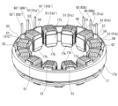
- FIG. It is a perspective view showing a stator provided for this embodiment. It is a top view which shows some stators.
- FIG. 7 is a view in the direction of arrow A in FIG. 6
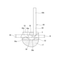
- FIG. 8 is a cross-sectional view taken along line BB of FIG. 7; It is a bird's-eye view of the insulator provided for this embodiment.
- FIG. 4 is a bird's-eye view of the stator showing a state in which no coil is wound;
- FIG. 4 is a front view showing a state in which a cover member of the control mechanism provided for the present embodiment is removed;
- FIG. 6 is a plan view showing a second embodiment of the present invention and showing part of a stator; 12. It is a C arrow directional view of FIG.
- FIG. 1 is a partial vertical cross-sectional view showing the valve timing control device according to this embodiment
- FIG. 2 is an exploded perspective view showing the components of the reduction mechanism side and the brushless motor provided for this embodiment.
- the valve timing control device is applied to the intake side, and as shown in FIGS. and a phase change mechanism arranged between the sprocket 1 and the camshaft 2 to change the relative rotational phase between the sprocket 1 and the camshaft 2 according to the engine operating state.
- the sprocket 1 includes an annular sprocket body 1a and a gear that is integrally provided on the outer periphery of the sprocket body 1a and receives rotational force from the crankshaft of an internal combustion engine via a timing chain (not shown) wound around the outer periphery. a portion 1b;
- a chain case (not shown) coupled to the cylinder block and cylinder head 01 of the internal combustion engine is provided on the outer periphery of the sprocket 1 .
- the internal gear forming portion 5 has a plurality of corrugated internal teeth 5a on its inner periphery.
- the sprocket body 1a is provided with a sliding bearing mechanism 6 between the inner peripheral surface on the side of the camshaft 2 and the outer peripheral surface of the driven member 9, which will be described later.
- the slide bearing mechanism 6 bears the sprocket 1 on the outer periphery of the driven member 9 so as to be relatively rotatable.
- a holding plate 8 made of a ferrous metal plate and formed in an annular shape is fixed to the rear end surface of the sprocket body 1a on the opposite side in the axial direction from the internal gear forming portion 5 .
- the holding plate 8 is integrally provided with a stopper projection 8b protruding toward the central axis at a predetermined position on the inner peripheral edge of the central hole 8a.
- the adapter 4 is made of a metal material and is fitted into the central hole 8a of the holding plate 8.
- the adapter 4 has an insertion hole 4a through which the cylindrical portion 9c of the driven member 9 is inserted, and has a stopper groove 4b at a predetermined position on the outer peripheral surface.
- the stopper recessed groove 4b is formed in an arc shape of a predetermined range along the outer circumference of the adapter 4, and the side surfaces of the stopper protrusion 8b come into contact with the circumferentially opposite side edges 4c and 4d from the circumferential direction, thereby allowing the sprocket to rotate. 1, the relative rotational position of the driven member 9 (camshaft 2) on the maximum advance side or the maximum retardation side is mechanically restricted.
- a front plate 15 is provided on the front end face of the sprocket 1 on the internal gear forming portion 5 side. As shown in FIGS. 1 and 2, the front plate 15 is formed by stamping, for example, an iron-based metal plate into an annular shape by press forming. 15a is formed through.
- the camshaft 2 has two drive cams per cylinder on its outer circumference that open intake valves (not shown).
- the camshaft 2 has an insertion hole 2b formed along the inner axial direction from the tip surface of the one end 2a, and a shaft portion 14b of a cam bolt 14, which will be described later, is inserted.
- a female threaded portion 2c is formed on the inner peripheral surface of the insertion hole 2b on the distal end side, to which the male threaded portion 14c formed at the distal end portion of the shaft portion 14b of the cam bolt 14 is screwed.
- the driven member 9 is integrally formed of ferrous metal, and has a disk-shaped main body 9a as shown in FIGS.
- a bolt insertion hole 9b into which the shaft portion 14b of the cam bolt 14 is inserted is formed through the disk-shaped main body 9a at the center position.
- the driven member 9 is axially fastened and fixed to the camshaft 2 by a cam bolt 14 in a state where the tip of the cylindrical portion 9c is axially fitted into a cylindrical groove formed inside the one end portion 2a of the camshaft 2.
- the slide bearing mechanism 6 includes an annular bearing recess 10 formed on the inner peripheral surface of the sprocket main body 1a, and a bearing recess 10 provided on the outer peripheral surface of the disk-shaped main body 9a. and a journal portion 11 disposed therein.
- the journal portion 11 has an annular outer peripheral surface that is slidable on the entire sliding bearing surface of the bearing recessed portion 10 .
- the other end surface of the journal portion 11 on the holding plate 8 side in the axial direction is slidable on the inner surface of the inner peripheral portion of the holding plate 8 .
- the phase change mechanism comprises a brushless motor 12 arranged on the front end side of the front plate 15, and decelerates the rotational force transmitted from the brushless motor 12 through the Oldham's coupling. and a speed reducer 13 that transmits power to the camshaft 2 .
- the speed reducer 13 is provided axially and independently of the brushless motor 12 , and each component is housed inside the sprocket 1 between the holding plate 8 and the front plate 15 .
- the speed reducer 13 includes a cylindrical shaft 30 partially disposed inside the sprocket body 1a, a ball bearing 31 provided on the outer circumference of the cylindrical shaft 30, and an internal gear structure provided on the outer circumference of the ball bearing 31.
- a plurality of rollers 32 rotatably held within the internal teeth 5a of the portion 5 and a disk-shaped main body 9a of the driven member 9 are provided integrally on the outer peripheral side to hold the plurality of rollers 32 in the rolling direction. and a retainer 33 that permits movement in the radial direction.
- the cylindrical shaft 30 has an eccentric shaft portion 30a disposed on the outer periphery of a needle bearing 34 provided on the outer periphery of the head portion 14a of the cam bolt 14, and the eccentric shaft portion 30a is integrally connected to the brushless motor 12 side. and a portion 30b.
- the eccentric shaft portion 30a is formed in a cylindrical shape whose axial length is longer than that of the needle bearing 34 in its axial direction. As shown in FIG. 2, the eccentric shaft portion 30a is slightly eccentric with respect to the axis Y of the cam bolt 14 because the thickness t of the eccentric shaft portion 30a varies in the entire circumferential direction.
- the connecting portion 30b is formed in a substantially circular shape with a uniform thickness, and is slightly thicker than the eccentric shaft portion 30a.
- the connecting portion 30b protrudes toward the brushless motor 12 from the inside of the sprocket body 1a through the insertion hole 15a of the front plate 15. As shown in FIG.
- the connecting portion 30b constitutes an Oldham coupling together with an intermediate member 28 of the brushless motor 12, which will be described later.
- the connecting portion 30b is formed with a fitting hole having a width across flats into which the cylindrical base portion 28a of the intermediate member 28 can be fitted from the axial direction.
- the needle bearing 34 is fixed to a plurality of needle rollers 34a rolling on the outer peripheral surface of the head portion 14a of the cam bolt 14 and to a step surface formed on the inner peripheral surface of the eccentric shaft portion 30a. and a cylindrical shell 34b having a plurality of grooves that rollably retains 34a.
- the ball bearings 31 are arranged in such a manner that they substantially overlap each other at the radial position of the needle bearings 34 .
- the ball bearing 31 is composed of an inner ring 31a, an outer ring 31b, balls 31c interposed between the two rings, and a cage for holding the balls 31c.
- the inner ring 31a is formed to have a greater thickness and width than the outer ring 31b, and is press-fitted and fixed to the outer peripheral surface of the eccentric shaft portion 30a.
- the outer ring 31b is in a free state without being fixed in the axial direction. That is, the outer ring 31b has one end face on the brushless motor 12 side in the axial direction with the inner side face of the front plate 15 with a minute clearance therebetween. The other end surface of the outer ring 31b in the axial direction also has a minute clearance with the rear surface of the disk-shaped main body 9a of the driven member 9 facing thereto.
- the outer ring 31b is in contact with the outer peripheral surface so that the outer peripheral surface of each roller 32 can roll.
- An annular clearance is formed between the outer peripheral surface of the outer ring 31b and the inner surface of the retainer 33. As shown in FIG. Therefore, the ball bearing 31 as a whole can eccentrically move in the radial direction with the eccentric rotation of the eccentric shaft portion 30a through the clearance.
- the retainer 33 is formed in a cylindrical shape and is provided integrally with the outer peripheral portion of the disk-shaped main body 9a. That is, the retainer 33 linearly protrudes toward the front plate 15 from the base side of the journal portion 11 of the disk-shaped main body 9a.
- the retainer 33 is formed with a plurality of substantially rectangular roller retaining holes 33a extending along the axial direction for retaining the plurality of rollers 32 so that they can roll.
- the plurality of roller holding holes 33a are provided at equal intervals in the circumferential direction of the retainer 33, and are formed in a rectangular shape that is elongated in the front-rear direction and is closed at the tip side thereof. Further, the total number of roller holding holes 33a (the number of rollers 32) is smaller than the total number of teeth of the internal teeth 5a of the internal gear forming portion 5, thereby obtaining a predetermined reduction ratio. It has become.
- the reduction gear 13 and the Oldham's coupling are supplied with lubricating oil via a lubricating oil supply mechanism.
- the lubricating oil supply mechanism is formed through the oil supply passage 35 formed axially inside the camshaft 2 and the inner peripheral portion of the adapter 4 in the width direction.
- FIG. 3 is a longitudinal sectional view of a brushless motor provided for this embodiment
- FIG. 4 is a sectional view showing an enlarged part of FIG. 3
- FIG. 5 is a perspective view showing a stator provided for this embodiment.
- 6 is a plan view showing part of the stator
- FIG. 7 is a view in the direction of arrow A in FIG. 6
- FIG. 8 is a cross-sectional view taken along the line BB in FIG.
- the brushless motor 12 is a DC three-phase induction motor, and as shown in FIGS.
- a stator (stator) 17 which is a magnetic member fixed to the motor housing 16, a motor output shaft 18 arranged on the inner peripheral side of the stator 17, a rotor 19 fixed to the outer periphery of the motor output shaft 18, and a motor housing 16 and a control mechanism 20 provided on the opposite side of the sprocket 1.
- the motor housing 16 is formed, for example, by bending an iron-based metal plate into a cup shape, and a stator housing space S for housing the stator 17 and the like is formed therein.
- the motor housing 16 has a through hole 16 b through which the motor output shaft 18 is inserted through the oil seal 22 , substantially in the center of the bottom wall 16 a on the speed reducer 13 side.
- the through hole 16b is formed inside a tubular portion 16c formed by bending the center of the bottom wall 16a into a tubular shape.
- the motor housing 16 is integrally provided with a flange portion 16d protruding radially outward on the outer periphery of the open end of the rear end portion.
- the flange portion 16d is integrally provided with three bracket pieces 16e at approximately 120° positions in the circumferential direction.
- bolt insertion holes 16f into which the shaft portions of the three bolts 21 are inserted are formed through the three bracket pieces 16e, respectively.
- Each bolt 21 fastens and fixes the motor housing 16 and a later-described casing 40 of the control mechanism 20 together, and also fixes them to a chain case (not shown).
- each bolt 21 has a male threaded portion 21a on the outer periphery on the tip side thereof screwed into a female threaded hole formed in the chain case to fasten the motor housing 16 and the casing 40 together and to fix them to the chain case. ing. It is also possible to increase the number of bolt insertion holes 16f and bolts 21 to three or more.
- the oil seal 22 has a general structure, the outer peripheral surface of which is press-fitted into the inner peripheral surface of the through hole 16b, while the inner peripheral seal piece is pressed against the outer peripheral surface of the one end portion 18a of the motor output shaft 18 by a backup spring. They are in slidable contact. Thus, the oil seal 22 restricts the inflow of oil from the speed reducer 13 into the motor housing 16 .
- the stator 17 includes an annular stator core (iron core) 17a provided on the outer circumference of the insulator 50, and a plurality of stator cores (iron cores) 17a provided on the inner circumference of the insulator 50 (12 in this embodiment). and three-phase U, V, and W coils 51 wound around the outer circumference of each tooth portion 17b.
- the stator core 17a is formed by laminating many steel plates.
- Each tooth portion 17b is provided with a metal piece 17c made of a magnetic material at the radially inner tip portion.
- FIG. 9 is a bird's-eye view of an insulator provided for this embodiment
- FIG. 10 is a bird's-eye view of a stator showing a state in which no coil is wound.
- the insulator 50 is formed in an annular shape from an insulating synthetic resin material, and has twelve teeth 17b protruding radially inward on its inner periphery.
- the coils 51 described above are wound around the tooth portions 17b, respectively.
- the insulator 50 is integrally provided with a pair of projecting shelf portions 52 extending in an arc shape in the circumferential direction at predetermined positions on the outer peripheral surface of the annular portion 50a at the upper end in the axial direction. Both shelf portions 52 are formed on one side of the semicircular side with respect to the diametrical line of the annular portion 50a. are provided integrally, and a pair of second side walls 54 that are substantially continuous with the first side wall 53 with a gap in the circumferential direction are integrally provided.
- the first side wall 53 is formed along the inner edge of the upper surface of the shelf portion 52 (annular portion 50a) along the circumferential direction and has a height greater than that of the first winding portion 51a. It is formed slightly higher than the height.
- the first side wall 53 has a radially convex first convex portion 55 on one end side of the outer circumferential surface on the side of the second side wall 54 in the circumferential direction, and has a radially convex portion 55 on the other end side in the circumferential direction. It has a second protrusion 56 that protrudes in the direction.
- the second side wall 54 has basically the same structure as the first side wall 53, and has a radially convex third protrusion 57 on one end side of the outer circumferential surface on the side of the first side wall 53 in the circumferential direction. In addition, it has a fourth convex portion 58 that protrudes in the radial direction on the other end side in the circumferential direction.
- Each of the first to fourth projections 55 to 58 is formed in a substantially rectangular block shape, and each upper surface is formed to have substantially the same height as the first and second side walls 53 and 54, while each lower surface is is provided slightly apart from the upper surface of the shelf portion 52, and a holding gap C is formed between the upper surface of the shelf portion 52 and the lower surfaces of the projections 55-58.
- the holding gap C is formed such that its vertical width W is slightly smaller than the outer diameter W1 of a plurality of lead wires 60 to 62 (60′ to 62′ are the same), which will be described later.
- Circumferential portions 60a to 62a of the routed lead wires 60 to 62 can be held between the upper surface of the shelf portion 52 and the lower surfaces of the projections 55 to 58 by light press-fitting.
- circumferential portions 60a to 62a of lead wires 60 to 62 are located within holding gaps C on the upper surface of each shelf 52 corresponding to the projections 55 to 58.
- Relief portions 59 that are partially absorbed when held are provided respectively.
- Each escape portion 59 is composed of a shallow groove portion 59a formed in a rectangular shape along the circumferential direction of the upper surface of each shelf portion 52, and a deep groove portion 59b formed in the longitudinal center of the shallow groove portion 59a. It is
- each coil 51 includes a U-phase first winding portion 51a (51a'), a V-phase second winding portion 51b (51b'), and a W-phase third winding portion 51b (51b'). It has a winding portion 51c (51c').
- the lead wires extending from the ends of the winding portions 51a to 51c (51a' to 51c') of each phase are first, second and third lead wires 60, 61 and 62 on the winding start side, and windings. It has first, second and third lead lines 60', 61' and 62' on the end side.
- lead wires 60 to 62 and 60' to 62' are connected to corresponding through holes 42a of a circuit board 42, which will be described later, by soldering or the like. It is well known that an insulating film is formed on the entire surface of each winding portion including the winding portions 51a to 51c (51a' to 51c').
- the first lead wire 60 is pulled out from the end of the first winding portion 51a and extends toward the center of the first side wall 53 at one circumferential end 53a of the first side wall 53. It has a bent first circumferential portion 60a and a first tip portion 60b bent in the axial direction (upward in the drawing) at the first convex portion 55 from here.
- the first circumferential portion 60a bent at one end portion 53a of the first side wall 53 is routed along the outer surface of the first side wall 53 as it is, and the upper surface of the shelf portion 52 and the lower surface of the first convex portion 55 are separated from each other. It is inserted into the holding gap C between them and held in a lightly press-fitted state, that is, in a sandwiched state. At this time, the first circumferential portion 60a is partially absorbed by the first relief portion 59, as shown in FIG.
- the first tip portion 60b rises vertically or substantially vertically in the axial direction from the edge of the first convex portion 55 along one side surface.
- the first lead wire 60 has a first stripped portion 64 in which the surface insulating coating is stripped from the first circumferential portion 60a to the first tip portion 60b.
- This first peeled portion 64 has a first peeled edge portion 64a, which is the beginning of peeling, at a substantially central position in the axial direction of the first circumferential portion 60a, and peeled from there to the edge of the first tip portion 60b.
- the second lead wire 61 is pulled out from the end of the second winding portion 51b and extends along the circumferential direction of the second side wall 54 at one circumferential end 54a of the second side wall 54.
- a second circumferential portion 61a that is bent and extends from here to the fourth convex portion 58 and the third convex portion 57, that is, in the direction of the first lead line 60, and the tip side of the second circumferential portion 61a and a second tip portion 61b that is bent in the axial direction (upward in FIG. 7) at the third convex portion 57.
- the second circumferential portion 61a bent at one end portion 54a of the second side wall 54 is routed as it is along the outer surface of the second side wall 54, and the upper surface of the shelf portion 52 and the fourth protrusion 58 and third protrusion 58 are connected to each other. It is inserted into the holding gaps C, C between the lower surfaces of the portion 57 and held in a lightly press-fitted state, that is, in a sandwiched state. At this time, the second circumferential portion 61 a is partially absorbed by the second relief portion 59 and the third relief portion 59 .
- the second tip portion 61b rises vertically or substantially vertically in the axial direction from the edge of the third convex portion 57 along one side surface on the first convex portion 55 side.
- the second lead wire 61 has a second stripped portion 64 from which the surface insulating coating is stripped from the second circumferential portion 61a to the second tip portion 61b.
- the second peeling edge portion 64a which is the beginning of peeling, is located at a position substantially on the tip side in the axial direction of the second circumferential portion 61a, and peeled from there to the tip edge of the second tip portion 61b. It is
- the second tip 61b is brought as close as possible to the first tip 60b of the first lead wire 60. be able to.
- the third lead wire 62 is pulled out from the end of the third winding portion 51c and connected to the other end 53b of the first side wall 53 in the circumferential direction.
- a third circumferential portion 62a that is bent along the circumferential direction and extends from here to the second convex portion 56, that is, in the direction of the first lead line 60, and the distal end side of the third circumferential portion 62a and a third distal end portion 62b that is bent in the axial direction (upward in the drawing) at the convex portion 56.
- the third circumferential portion 62a bent at the other end portion 53b of the first side wall 53 is routed along the outer surface of the first side wall 53 as it is, and is connected to the upper surface of the shelf portion 52 and the lower surface of the second convex portion 56. It is inserted into the holding gap C between and held in a lightly press-fitted state, that is, in a sandwiched state. At this time, the third circumferential portion 62 a is partially absorbed by the fourth relief portion 59 .
- the third tip portion 62b rises vertically or substantially vertically in the axial direction from the edge of the second convex portion 56 along one side surface on the first convex portion 55 side.
- the third lead wire 62 has a third stripped portion 64 from which the surface insulating coating is stripped from the third circumferential portion 62a to the third tip portion 62b.
- the third peeling edge portion 64a which is the beginning of peeling, is located at a position substantially on the tip side in the axial direction of the third circumferential portion 62a, and peeled from there to the tip edge of the third tip portion 62b. It is
- the third tip 62b is brought as close as possible to the first tip 60b of the first lead wire 60. be able to.
- the length of the three side walls located on the opposite side of the first and second side walls 53 and 54 of the insulator 50 have substantially the same structure as the first and second side walls.
- the three lead wires 60' to 62' have substantially the same configuration.
- the motor output shaft 18 is made of, for example, an iron-based metal material, and as shown in FIG.
- the one end portion 18a has a width across flat portion (not shown) formed along the tangential direction on the outer surface, and a pair of fitting parts (not shown) cut in a direction perpendicular to the width across flat portion (not shown).
- a groove is formed.
- a stopper member 39 capable of expansion/contraction deformation that restricts the movement of the intermediate member 28 toward the cam bolt 14 is radially fitted and fixed in both fitting grooves.
- the other end portion 18b of the motor output shaft 18 is rotatably supported by a bearing portion 29 provided in the casing 40 of the control mechanism 20 and described later.
- the one end portion 18a is arranged close to the head portion 14a of the cam bolt 14 with a slight gap from the rotation axis direction.
- the one end portion 18a can be axially inserted into the hexagonal groove formed in the front end face of the head portion 14a as a whole including the stopper member 39. As shown in FIG.
- An intermediate member 28 is provided at the one end portion 18a.
- the intermediate member 28 constitutes a part of an Oldham coupling which is a joint connected to the speed reducer 13, and as shown in FIG. It has a base 28a.
- the cylindrical base portion 28a has a pair of flat surfaces on both sides of the circular outer surface, that is, at 180° positions in the circumferential direction. ing.
- a through hole (not shown) into which the width across flat portion of the one end portion 18a of the motor output shaft 18 is inserted is formed at the central position of the cylindrical base portion 28a.
- the through hole has a pair of opposing surfaces extending in the radial direction from the rotating shaft of the motor output shaft 18 on the circular inner peripheral surface.
- the through-hole is formed in an oval shape that is long in the radial direction and similar to the outer shape of the cylindrical base portion 28a. Therefore, the intermediate member 28 can move in the radial direction (vertical direction in FIG. 1) with respect to the one end portion 18a of the motor output shaft 18 via the oval through hole.
- the rotor 19, as shown in FIG. It is provided with (eight in this embodiment) holding holes 24 and eight permanent magnets 25 inserted and held in each of the holding holes 24 .
- the rotor core 23 and the permanent magnets 25 are provided coaxially with respect to the motor output shaft 18 .
- the rotor core 23 is integrally formed of a metal material and has a substantially cylindrical outer peripheral portion 23 a and a cylindrical inner peripheral portion 23 b fixed to the motor output shaft 18 .
- An intermediate portion between the outer peripheral portion 23a and the inner peripheral portion 23b is formed in a honeycomb shape.
- the outer peripheral portion 23a has a shape in which eight arcuate blocks are annularly connected along the circumferential direction, and the inner peripheral surface 23c is formed in an octagonal shape.
- gaps having a substantially triangular cross-section are formed outside between the blocks to be filled with a covering portion 26 made of a synthetic resin material.
- An insertion hole 23d into which the motor output shaft 18 is inserted and fixed is formed through the inner peripheral portion 23b in the central axial direction.
- Each holding hole 24 is formed through each block of the outer peripheral portion 23a along the inner axial direction.
- the holding hole 24 is formed with a uniform cross-sectional area from one end opening edge on the control mechanism 20 side in the axial direction to the other end opening edge on the reduction gear 13 side.
- the permanent magnet 25 is made of a general composite alloy material (rare earth sintered magnet) such as neodymium, and is formed in a substantially square shape in a plan view with a predetermined thickness. That is, each side has the same length. Each side of the permanent magnet 25 is shorter than the widthwise length of the holding hole 24. When the permanent magnet 25 is inserted and held in the holding hole 24, both side surfaces and the holding hole facing the both side surfaces are formed. A gap is formed between the opposite inner surfaces of 24 in the width direction.
- a general composite alloy material such as neodymium
- each permanent magnet 25 has projecting portions 25a projecting from one end opening edge of each holding hole 24 at one end on the side of the control mechanism 20 in this axial direction.
- each permanent magnet 25 has a recessed portion in which the other end on the side of the speed reducer 13 in the axial direction is recessed further inside the holding hole 24 than the other end opening edge of each holding hole 24 .
- the outer peripheral portion 23a of the rotor core 23 is entirely covered with a covering portion 26 made of a synthetic resin material, which is a non-magnetic material, on the protruding portion 25a side and the receding portion side.
- the covering portion 26 has an annular shape so as to cover the entire outer peripheral surface of each projecting portion 25a. Also, the covering portion 26 is filled into the holding hole 24 from the other end opening edge of the holding hole 24 so as to close the recessed portions, and is formed in an annular shape as a whole.
- FIG. 11 is a front view showing a state in which the cover member of the control mechanism provided for this embodiment is removed.
- the control mechanism 20 has a box-shaped casing 40 made of synthetic resin, for example, and a cover member 41 that closes the front end opening of the casing 40 .
- the casing 40 has a rectangular partition wall 40a, which is a partition wall arranged on the motor housing 16 side, and a rectangular frame-shaped peripheral wall 40b rising from the outer peripheral edge of the partition wall 40a.
- a board accommodation space S1 is formed inside the casing 40 and the cover member 41 .
- the partition wall 40a is integrally provided with a cylindrical cylindrical portion 40c in the center, and is integrally provided with four small-diameter cylindrical bosses (not shown) at the four corners of the inner surface.
- Each of the columnar bosses has a female screw hole (not shown) formed at the tip thereof, into which four screws 43 for fixing the rectangular circuit board 42 are screwed.
- the partition wall 40a has a plurality of lead-out holes 40d into which the leading ends 60b to 62b of the lead wires 60 to 62 at the winding start side and the winding end are inserted in the direction of the circuit board 42, respectively. Penetration is formed.
- the partition wall 40a is formed in a conical wall 40e projecting toward the circuit board 42 from the edge of each drawing hole 40d.
- a guiding conical concave guide portion 40f is provided.
- the circuit board 42 is formed in a substantially convex shape in a plan view, and is housed in the board housing space S1.
- the circuit board 42 has a conductive circuit (not shown) such as a bus bar for supplying power to the brushless motor 12, and has a plurality of terminal strips of a connector 44, which will be described later, connected by soldering to one side of the circuit board 42. Hall terminals are provided for coupling.
- the circuit board 42 has an insertion hole 42a through which the cylindrical portion 40c can be inserted, and four small-diameter screw insertion holes through which screws 43 are inserted at the four corners. ing.
- the circuit board 42 is such that the leading ends 60b to 62b of the lead wires 60 to 62 (60' to 62') on the winding start side and the winding end side are connected to the partition wall 40a.
- a plurality of through-holes 42a are formed to be inserted through the drawing holes 40d.
- the tip portions 60b to 62b drawn out from each through hole 42a and the edge of each through hole 42a are electrically connected by a soldering portion 42b.
- the fan-shaped shaded area shown in FIG. 11 is the forbidden zone.
- the board accommodation space S1 also contains a rotation detection sensor, which is a magnetic sensor that conducts with the circuit board 42 and controls the drive of the brushless motor 12, an aluminum electrolytic capacitor, a normal coil, and a common coil.
- a rotation detection sensor which is a magnetic sensor that conducts with the circuit board 42 and controls the drive of the brushless motor 12, an aluminum electrolytic capacitor, a normal coil, and a common coil.
- a plurality of electronic components such as coils and ceramic capacitors are housed and arranged.
- the tubular portion 40c is formed in a cylindrical shape with a bottom and has a bearing holding groove 40g for accommodating and holding the bearing portion 29 therein.
- the bearing portion 29 is a plain bearing, and is made of a metallic material with low frictional resistance and is formed in an annular shape that is thick in the axial direction.
- the outer peripheral surface of the bearing portion 29 is press-fitted and fixed to the inner peripheral surface of the bearing holding groove 40g of the cylindrical portion 40c.
- the bearing portion 29 rotatably supports the outer peripheral surface of the other end portion 18b of the motor output shaft 18 in a fixing hole 29a penetrating in the direction of the central axis.
- the peripheral wall 40b is integrally provided with a connector 44 that serves as both a signal and a power supply on the outer periphery.
- One end of a pair of terminal strips is arranged inside the connector 44 .
- the terminal piece has the other end (not shown) located in the board accommodation space S1 and is connected to the hole terminal of the conduction circuit of the circuit board 42 by soldering.
- One end of the pair of terminal strips is partially connected to an unillustrated engine control unit (ECU) via female terminals to a battery as a power source. Another part outputs information signals such as rotation angle signals detected by the rotation detection sensor to the ECU.
- ECU engine control unit
- the cover member 41 is formed of, for example, an aluminum alloy material in a plate-like square shape, and as shown in FIG. there is
- the ECU detects the current engine operating status based on information signals from various sensors (not shown) such as a crank angle sensor, air flow meter, water temperature sensor, and accelerator position sensor, and controls the engine based on this. ing.
- the ECU controls the rotation of the motor output shaft 18 by energizing the coils 51 of the brushless motor 12 based on the information signals and signals from the rotation detection sensor.
- the reduction gear 13 controls the relative rotational phase of the camshaft 2 with respect to the timing sprocket 1 .
- a control current from the control unit is applied to each coil 51 of the brushless motor 12 to rotate the motor output shaft 18 forward and backward.
- the rotational force of the motor output shaft 18 is transmitted to the cylindrical shaft 30 via the Oldham's coupling, and reduced rotational force is transmitted to the camshaft 2 by the operation of the speed reducer 13 .
- the camshaft 2 rotates forward and backward relative to the timing sprocket 1 to convert the relative rotation phase. Therefore, the opening/closing timing of each intake valve is controlled to advance or retard.
- the brushless motor 12 of this embodiment has the following effects.
- the first to third lead wires 60 to 62 are freely positioned at arbitrary positions by the circumferential portions 60a to 62a extending along the outer surfaces of the sidewalls 53 and 54 of the insulator 50. It is possible to turn around. As a result, for example, the second and third tip portions 61b and 62b of the second and third lead wires 61 and 62 are brought as close as possible to the first tip portion 60b of the first lead wire 60 in the circumferential direction. be able to. In other words, the distance between the tips 60b to 62b connected to the circuit board 42 can be shortened.
- the circumferential portions 60a to 62a of the lead lines 60 to 62 can be freely routed along the outer surfaces of the side walls 53 and 54. It is possible to reduce the distance between the tip portions 60b to 62b and gather them together.
- the outer diameter of the circuit board 42 for example, can be reduced by the amount corresponding to the shortened distance between the tip portions 60b to 62b, and the degree of freedom in the outer shape and layout of the circuit board 42 is improved.
- the ease of mounting the device on the internal combustion engine and the degree of freedom in layout are improved as the circuit board 42 is miniaturized.
- tip portions 60b to 62b of the first to third lead wires 60 to 62 are directly connected to the through holes 42a of the circuit board 42, busbar terminals in the circuit board 42 are not required. As a result, the number of parts can be reduced and the cost can be lowered.
- the tip portions 60b to 62b of the first to third lead wires 60 to 62 are pulled out from the drawing holes 40d of the partition wall 40a toward the circuit board 42, the tip portions 60b to 62b are attached to the respective guides. Guided by the portion 40f, it is inserted into each lead-out hole 40d, and further smoothly guided into each through-hole 42a of the circuit board 42. As shown in FIG. This facilitates the work of drawing out the tip portions 60b to 62b of the first to third lead wires 60 to 62 from the first to third winding portions 51a to 51c to the circuit board .
- the lead wires 60 to 62 can be easily bent in the axial direction by the first to third projections 55 to 57 provided on the first and second side walls 53 and 54 of the insulator 50, and each projection can be easily bent.
- the positions of the portions 55-57 determine the bending positions of the lead lines 60-62. This facilitates routing of the lead wires 60 to 62 and bending of the tip portions 60b to 62b.
- first to third lead lines 60 to 62 are bent in the circumferential direction using the circumferential ends 53a, 53b, 54a of the first and second side walls 53, 54 extending in the axial direction, Furthermore, since it can be bent in the axial direction (in the direction of the circuit board 42) at the first, second, and third projections 55, 56, and 57, continuous handling work can be easily performed.
- the first convex portion 55 of the first side wall 53 is provided at a position spaced apart from the upper surface of the shelf portion 52 of the insulator 50 in the vertical direction.
- the first circumferential portion 60a When inserting the first circumferential portion 60a therein, it is possible to sandwich and hold it between the lower surface of the first convex portion 55 and the upper surface of the shelf portion 52 in a light press-fit state. This makes it possible to position and stably hold the first circumferential portion 60a.
- the second circumferential portion 61a and the third circumferential portion 62a are identical to the same applies to the second circumferential portion 61a and the third circumferential portion 62a. and the lower surfaces of the fourth convex portion 58 and the third convex portion 57 by light press-fitting. Further, the third circumferential portion 62a is held between the upper surface of the first shelf portion 52 and the lower surface of the second convex portion 56 by light press-fitting.
- the first to fourth relief portions 59 allow light press-fitting. Since the pressing force can be reduced, the work of inserting the first to third circumferential portions 60a to 62a into the holding gaps C becomes easier.
- the peeling is generally Relatively large variations of about ⁇ 2 mm are likely to occur in the position of the peeled edge part of the part.
- the variation can be absorbed.
- the position of the peeled cord portion 64a is not on the side of the tip portions 60b to 62b of the lead wires 60 to 62, but on the side of the circumferential portions 60a to 62a, even if the positions of the peeled cord portions 64a are not uniform. However, it can absorb these, so there is no effect.
- first and second side walls 53 and 54 of the insulator 50 with which the circumferential portions 60a to 62a are in contact are made of an insulating material, even if the stripped portion 64 comes into contact with the side walls 53 and 54, there is a problem of insulation. does not occur.
- the insulator 50 has a substantially semicircular shelf portion 52 formed along the inner peripheral edge of the upper surface of the annular portion 50a continuously and integrally.
- Side walls 53 and 54 provided on the inner peripheral edge of the upper surface of one shelf portion 52 (annular portion 50a) are arranged independently at positions corresponding to the first to third winding portions 51a to 51c and 51a' to 51c'. is provided.
- the first to third lead wires 60 to 62 at the beginning of winding and the first to third lead wires 60' to 62 at the end of winding have respective tip portions 60b to 62b and 60b' to 62b', respectively, in the circumferential direction.
- 60a to 62a and 60a' to 62a' are arranged at substantially equal intervals in the circumferential direction via respective projections 55 to 57 that hold 60a' to 62a'.
- the group of first lead wires 60 to 62 at the start of winding and the group of first lead wires 60' to 62' at the end of winding are arranged close to each other in the circumferential direction, as indicated by the arrows in the figure.
- the tip portion 61b of the second lead wire 61 at the start of winding and the tip portion 62b' of the third lead wire 62' at the end of winding are arranged in close proximity.
- the winding start and winding end lead wires 60 to 62 and 60' to 62' can be freely and arbitrarily routed to allow them to approach in the circumferential direction.
- the outer diameter of the circuit board 42 can be made even smaller than in the first embodiment, and the outer shape and layout of the circuit board 42 can be made wider. As a result, the size of the casing 40 of the control mechanism 20 can be reduced, so that the mountability to the internal combustion engine is further improved.
- the present invention is not limited to the configuration of each of the embodiments described above. can be arbitrarily changed by changing the formation position and the number of . Therefore, the size and specifications of the circuit board 42 can be changed arbitrarily.
- IPM structure in which the permanent magnets 25 are embedded in the rotor core 23, but a so-called SPM structure in which the permanent magnets 25 are arranged on the outer circumference of the rotor core 23 may be used.
- Brushless motor 12 includes not only valve timing control devices for internal combustion engines, but also various vehicle motors such as power steering motors, power window motors, sunroof motors, and power seat motors, as well as home appliances such as air conditioners. It can also be applied to motors used in products.
Landscapes
- Engineering & Computer Science (AREA)
- Mechanical Engineering (AREA)
- General Engineering & Computer Science (AREA)
- Power Engineering (AREA)
- Valve Device For Special Equipments (AREA)
- Connection Of Motors, Electrical Generators, Mechanical Devices, And The Like (AREA)
Priority Applications (2)
| Application Number | Priority Date | Filing Date | Title |
|---|---|---|---|
| JP2023570793A JPWO2023127450A1 (https=) | 2021-12-28 | 2022-12-08 | |
| CN202280082844.8A CN118435499A (zh) | 2021-12-28 | 2022-12-08 | 无刷电机及内燃机的气门正时控制装置 |
Applications Claiming Priority (2)
| Application Number | Priority Date | Filing Date | Title |
|---|---|---|---|
| JP2021-213730 | 2021-12-28 | ||
| JP2021213730 | 2021-12-28 |
Publications (1)
| Publication Number | Publication Date |
|---|---|
| WO2023127450A1 true WO2023127450A1 (ja) | 2023-07-06 |
Family
ID=86998613
Family Applications (1)
| Application Number | Title | Priority Date | Filing Date |
|---|---|---|---|
| PCT/JP2022/045298 Ceased WO2023127450A1 (ja) | 2021-12-28 | 2022-12-08 | ブラシレスモータ及び内燃機関のバルブタイミング制御装置 |
Country Status (3)
| Country | Link |
|---|---|
| JP (1) | JPWO2023127450A1 (https=) |
| CN (1) | CN118435499A (https=) |
| WO (1) | WO2023127450A1 (https=) |
Cited By (1)
| Publication number | Priority date | Publication date | Assignee | Title |
|---|---|---|---|---|
| DE102024125607A1 (de) | 2024-09-06 | 2026-03-12 | Bayerische Motoren Werke Aktiengesellschaft | Rotor mit einem Stirnseitendeckel |
Citations (4)
| Publication number | Priority date | Publication date | Assignee | Title |
|---|---|---|---|---|
| JPS63109549U (https=) * | 1986-12-26 | 1988-07-14 | ||
| JPS63202147U (https=) * | 1987-06-19 | 1988-12-27 | ||
| JP2010213527A (ja) * | 2009-03-12 | 2010-09-24 | Daikin Ind Ltd | 固定子、モータ及び圧縮機 |
| JP2021016223A (ja) * | 2019-07-10 | 2021-02-12 | 株式会社ミクニ | 車載用ブラシレスモータ装置およびその製造方法 |
-
2022
- 2022-12-08 WO PCT/JP2022/045298 patent/WO2023127450A1/ja not_active Ceased
- 2022-12-08 CN CN202280082844.8A patent/CN118435499A/zh active Pending
- 2022-12-08 JP JP2023570793A patent/JPWO2023127450A1/ja active Pending
Patent Citations (4)
| Publication number | Priority date | Publication date | Assignee | Title |
|---|---|---|---|---|
| JPS63109549U (https=) * | 1986-12-26 | 1988-07-14 | ||
| JPS63202147U (https=) * | 1987-06-19 | 1988-12-27 | ||
| JP2010213527A (ja) * | 2009-03-12 | 2010-09-24 | Daikin Ind Ltd | 固定子、モータ及び圧縮機 |
| JP2021016223A (ja) * | 2019-07-10 | 2021-02-12 | 株式会社ミクニ | 車載用ブラシレスモータ装置およびその製造方法 |
Cited By (1)
| Publication number | Priority date | Publication date | Assignee | Title |
|---|---|---|---|---|
| DE102024125607A1 (de) | 2024-09-06 | 2026-03-12 | Bayerische Motoren Werke Aktiengesellschaft | Rotor mit einem Stirnseitendeckel |
Also Published As
| Publication number | Publication date |
|---|---|
| JPWO2023127450A1 (https=) | 2023-07-06 |
| CN118435499A (zh) | 2024-08-02 |
Similar Documents
| Publication | Publication Date | Title |
|---|---|---|
| CN102235194B (zh) | 内燃机的配气正时控制装置 | |
| JP2013167181A (ja) | 内燃機関のバルブタイミング制御装置 | |
| CN104518601A (zh) | 内转子型马达 | |
| US10294829B2 (en) | Valve timing control device for internal combustion engine | |
| WO2023127450A1 (ja) | ブラシレスモータ及び内燃機関のバルブタイミング制御装置 | |
| JP5172491B2 (ja) | モータ | |
| US9935522B2 (en) | Motor device | |
| JP5823769B2 (ja) | 内燃機関のバルブタイミング制御装置 | |
| JP7256691B2 (ja) | 内燃機関のバルブタイミング制御装置 | |
| JP6914443B2 (ja) | モータ及びバルブタイミング調整装置 | |
| WO2022185681A1 (ja) | ブラシレスモータ | |
| JP2013036400A (ja) | 内燃機関のバルブタイミング制御装置 | |
| WO2017026240A1 (ja) | 内燃機関のバルブタイミング制御装置 | |
| WO2022264747A1 (ja) | ブラシレスモータ | |
| CN105525959A (zh) | 内燃机的气门正时控制装置 | |
| JP6719884B2 (ja) | 内燃機関のバルブタイミング制御装置 | |
| JP2021027591A (ja) | 電動モータと電動モータの製造方法及び内燃機関のバルブタイミング制御装置 | |
| JP2024149929A (ja) | ブラシレスモータ及び内燃機関のバルブタイミング制御装置 | |
| JP6542661B2 (ja) | 内燃機関のバルブタイミング制御装置 | |
| JP5976529B2 (ja) | 内燃機関のバルブタイミング制御装置及び該バルブタイミング制御装置に用いられるカバー部材 | |
| JP7038000B2 (ja) | 内燃機関のバルブタイミング制御装置 | |
| JP6808844B2 (ja) | 内燃機関のバルブタイミング制御装置 | |
| JP6838810B2 (ja) | 内燃機関のバルブタイミング制御装置 | |
| JP6878214B2 (ja) | 内燃機関のバルブタイミング制御装置 | |
| JP2019044603A (ja) | 内燃機関のバルブタイミング制御装置と該バルブタイミング制御装置に用いられる固定部材 |
Legal Events
| Date | Code | Title | Description |
|---|---|---|---|
| 121 | Ep: the epo has been informed by wipo that ep was designated in this application |
Ref document number: 22915677 Country of ref document: EP Kind code of ref document: A1 |
|
| WWE | Wipo information: entry into national phase |
Ref document number: 2023570793 Country of ref document: JP |
|
| WWE | Wipo information: entry into national phase |
Ref document number: 202280082844.8 Country of ref document: CN |
|
| NENP | Non-entry into the national phase |
Ref country code: DE |
|
| 122 | Ep: pct application non-entry in european phase |
Ref document number: 22915677 Country of ref document: EP Kind code of ref document: A1 |