WO2023120698A1 - 液滴吐出装置及びメンテナンス方法 - Google Patents
液滴吐出装置及びメンテナンス方法 Download PDFInfo
- Publication number
- WO2023120698A1 WO2023120698A1 PCT/JP2022/047599 JP2022047599W WO2023120698A1 WO 2023120698 A1 WO2023120698 A1 WO 2023120698A1 JP 2022047599 W JP2022047599 W JP 2022047599W WO 2023120698 A1 WO2023120698 A1 WO 2023120698A1
- Authority
- WO
- WIPO (PCT)
- Prior art keywords
- droplet ejection
- liquid
- colored liquid
- flow rate
- period
- Prior art date
- Legal status (The legal status is an assumption and is not a legal conclusion. Google has not performed a legal analysis and makes no representation as to the accuracy of the status listed.)
- Ceased
Links
Images







Classifications
-
- B—PERFORMING OPERATIONS; TRANSPORTING
- B41—PRINTING; LINING MACHINES; TYPEWRITERS; STAMPS
- B41J—TYPEWRITERS; SELECTIVE PRINTING MECHANISMS, i.e. MECHANISMS PRINTING OTHERWISE THAN FROM A FORME; CORRECTION OF TYPOGRAPHICAL ERRORS
- B41J2/00—Typewriters or selective printing mechanisms characterised by the printing or marking process for which they are designed
- B41J2/005—Typewriters or selective printing mechanisms characterised by the printing or marking process for which they are designed characterised by bringing liquid or particles selectively into contact with a printing material
- B41J2/01—Ink jet
-
- B—PERFORMING OPERATIONS; TRANSPORTING
- B05—SPRAYING OR ATOMISING IN GENERAL; APPLYING FLUENT MATERIALS TO SURFACES, IN GENERAL
- B05B—SPRAYING APPARATUS; ATOMISING APPARATUS; NOZZLES
- B05B15/00—Details of spraying plant or spraying apparatus not otherwise provided for; Accessories
- B05B15/50—Arrangements for cleaning; Arrangements for preventing deposits, drying-out or blockage; Arrangements for detecting improper discharge caused by the presence of foreign matter
-
- B—PERFORMING OPERATIONS; TRANSPORTING
- B05—SPRAYING OR ATOMISING IN GENERAL; APPLYING FLUENT MATERIALS TO SURFACES, IN GENERAL
- B05B—SPRAYING APPARATUS; ATOMISING APPARATUS; NOZZLES
- B05B12/00—Arrangements for controlling delivery; Arrangements for controlling the spray area
- B05B12/004—Arrangements for controlling delivery; Arrangements for controlling the spray area comprising sensors for monitoring the delivery, e.g. by displaying the sensed value or generating an alarm
- B05B12/006—Pressure or flow rate sensors
-
- B—PERFORMING OPERATIONS; TRANSPORTING
- B05—SPRAYING OR ATOMISING IN GENERAL; APPLYING FLUENT MATERIALS TO SURFACES, IN GENERAL
- B05B—SPRAYING APPARATUS; ATOMISING APPARATUS; NOZZLES
- B05B12/00—Arrangements for controlling delivery; Arrangements for controlling the spray area
- B05B12/08—Arrangements for controlling delivery; Arrangements for controlling the spray area responsive to condition of liquid or other fluent material to be discharged, of ambient medium or of target ; responsive to condition of spray devices or of supply means, e.g. pipes, pumps or their drive means
- B05B12/085—Arrangements for controlling delivery; Arrangements for controlling the spray area responsive to condition of liquid or other fluent material to be discharged, of ambient medium or of target ; responsive to condition of spray devices or of supply means, e.g. pipes, pumps or their drive means responsive to flow or pressure of liquid or other fluent material to be discharged
-
- B—PERFORMING OPERATIONS; TRANSPORTING
- B05—SPRAYING OR ATOMISING IN GENERAL; APPLYING FLUENT MATERIALS TO SURFACES, IN GENERAL
- B05B—SPRAYING APPARATUS; ATOMISING APPARATUS; NOZZLES
- B05B13/00—Machines or plants for applying liquids or other fluent materials to surfaces of objects or other work by spraying, not covered by groups B05B1/00 - B05B11/00
- B05B13/002—Machines or plants for applying coating liquids or other fluent materials by inkjet
-
- B—PERFORMING OPERATIONS; TRANSPORTING
- B05—SPRAYING OR ATOMISING IN GENERAL; APPLYING FLUENT MATERIALS TO SURFACES, IN GENERAL
- B05B—SPRAYING APPARATUS; ATOMISING APPARATUS; NOZZLES
- B05B13/00—Machines or plants for applying liquids or other fluent materials to surfaces of objects or other work by spraying, not covered by groups B05B1/00 - B05B11/00
- B05B13/02—Means for supporting work; Arrangement or mounting of spray heads; Adaptation or arrangement of means for feeding work
- B05B13/04—Means for supporting work; Arrangement or mounting of spray heads; Adaptation or arrangement of means for feeding work the spray heads being moved during spraying operation
- B05B13/0431—Means for supporting work; Arrangement or mounting of spray heads; Adaptation or arrangement of means for feeding work the spray heads being moved during spraying operation with spray heads moved by robots or articulated arms, e.g. for applying liquid or other fluent material to three-dimensional [3D] surfaces
-
- B—PERFORMING OPERATIONS; TRANSPORTING
- B05—SPRAYING OR ATOMISING IN GENERAL; APPLYING FLUENT MATERIALS TO SURFACES, IN GENERAL
- B05B—SPRAYING APPARATUS; ATOMISING APPARATUS; NOZZLES
- B05B15/00—Details of spraying plant or spraying apparatus not otherwise provided for; Accessories
- B05B15/50—Arrangements for cleaning; Arrangements for preventing deposits, drying-out or blockage; Arrangements for detecting improper discharge caused by the presence of foreign matter
- B05B15/58—Arrangements for cleaning; Arrangements for preventing deposits, drying-out or blockage; Arrangements for detecting improper discharge caused by the presence of foreign matter preventing deposits, drying-out or blockage by recirculating the fluid to be sprayed from upstream of the discharge opening back to the supplying means
-
- B—PERFORMING OPERATIONS; TRANSPORTING
- B41—PRINTING; LINING MACHINES; TYPEWRITERS; STAMPS
- B41J—TYPEWRITERS; SELECTIVE PRINTING MECHANISMS, i.e. MECHANISMS PRINTING OTHERWISE THAN FROM A FORME; CORRECTION OF TYPOGRAPHICAL ERRORS
- B41J2/00—Typewriters or selective printing mechanisms characterised by the printing or marking process for which they are designed
- B41J2/005—Typewriters or selective printing mechanisms characterised by the printing or marking process for which they are designed characterised by bringing liquid or particles selectively into contact with a printing material
- B41J2/01—Ink jet
- B41J2/135—Nozzles
- B41J2/165—Prevention or detection of nozzle clogging, e.g. cleaning, capping or moistening for nozzles
-
- B—PERFORMING OPERATIONS; TRANSPORTING
- B41—PRINTING; LINING MACHINES; TYPEWRITERS; STAMPS
- B41J—TYPEWRITERS; SELECTIVE PRINTING MECHANISMS, i.e. MECHANISMS PRINTING OTHERWISE THAN FROM A FORME; CORRECTION OF TYPOGRAPHICAL ERRORS
- B41J2/00—Typewriters or selective printing mechanisms characterised by the printing or marking process for which they are designed
- B41J2/005—Typewriters or selective printing mechanisms characterised by the printing or marking process for which they are designed characterised by bringing liquid or particles selectively into contact with a printing material
- B41J2/01—Ink jet
- B41J2/135—Nozzles
- B41J2/165—Prevention or detection of nozzle clogging, e.g. cleaning, capping or moistening for nozzles
- B41J2/16517—Cleaning of print head nozzles
- B41J2/1652—Cleaning of print head nozzles by driving a fluid through the nozzles to the outside thereof, e.g. by applying pressure to the inside or vacuum at the outside of the print head
- B41J2/16526—Cleaning of print head nozzles by driving a fluid through the nozzles to the outside thereof, e.g. by applying pressure to the inside or vacuum at the outside of the print head by applying pressure only
-
- B—PERFORMING OPERATIONS; TRANSPORTING
- B41—PRINTING; LINING MACHINES; TYPEWRITERS; STAMPS
- B41J—TYPEWRITERS; SELECTIVE PRINTING MECHANISMS, i.e. MECHANISMS PRINTING OTHERWISE THAN FROM A FORME; CORRECTION OF TYPOGRAPHICAL ERRORS
- B41J2/00—Typewriters or selective printing mechanisms characterised by the printing or marking process for which they are designed
- B41J2/005—Typewriters or selective printing mechanisms characterised by the printing or marking process for which they are designed characterised by bringing liquid or particles selectively into contact with a printing material
- B41J2/01—Ink jet
- B41J2/17—Ink jet characterised by ink handling
-
- B—PERFORMING OPERATIONS; TRANSPORTING
- B41—PRINTING; LINING MACHINES; TYPEWRITERS; STAMPS
- B41J—TYPEWRITERS; SELECTIVE PRINTING MECHANISMS, i.e. MECHANISMS PRINTING OTHERWISE THAN FROM A FORME; CORRECTION OF TYPOGRAPHICAL ERRORS
- B41J2/00—Typewriters or selective printing mechanisms characterised by the printing or marking process for which they are designed
- B41J2/005—Typewriters or selective printing mechanisms characterised by the printing or marking process for which they are designed characterised by bringing liquid or particles selectively into contact with a printing material
- B41J2/01—Ink jet
- B41J2/17—Ink jet characterised by ink handling
- B41J2/175—Ink supply systems ; Circuit parts therefor
-
- B—PERFORMING OPERATIONS; TRANSPORTING
- B41—PRINTING; LINING MACHINES; TYPEWRITERS; STAMPS
- B41J—TYPEWRITERS; SELECTIVE PRINTING MECHANISMS, i.e. MECHANISMS PRINTING OTHERWISE THAN FROM A FORME; CORRECTION OF TYPOGRAPHICAL ERRORS
- B41J2/00—Typewriters or selective printing mechanisms characterised by the printing or marking process for which they are designed
- B41J2/005—Typewriters or selective printing mechanisms characterised by the printing or marking process for which they are designed characterised by bringing liquid or particles selectively into contact with a printing material
- B41J2/01—Ink jet
- B41J2/17—Ink jet characterised by ink handling
- B41J2/18—Ink recirculation systems
-
- B—PERFORMING OPERATIONS; TRANSPORTING
- B41—PRINTING; LINING MACHINES; TYPEWRITERS; STAMPS
- B41J—TYPEWRITERS; SELECTIVE PRINTING MECHANISMS, i.e. MECHANISMS PRINTING OTHERWISE THAN FROM A FORME; CORRECTION OF TYPOGRAPHICAL ERRORS
- B41J25/00—Actions or mechanisms not otherwise provided for
- B41J25/304—Bodily-movable mechanisms for print heads or carriages movable towards or from paper surface
- B41J25/316—Bodily-movable mechanisms for print heads or carriages movable towards or from paper surface with tilting motion mechanisms relative to paper surface
Definitions
- the disclosed embodiments relate to a droplet ejection device and a maintenance method.
- Inkjet printers and inkjet plotters that use the inkjet recording method are known as printing devices.
- Such an inkjet printing apparatus is equipped with a droplet ejection head for ejecting liquid.
- a droplet ejection device includes a droplet ejection head, a supply section, and a control section.
- the droplet ejection head ejects droplets of the coloring liquid.
- the supply unit supplies the coloring liquid to the droplet ejection head.
- the control section controls each section.
- the control unit controls the supply unit during at least a part of the maintenance period after the ejection period for ejecting droplets of the colored liquid from the droplet ejection head so that the viscosity of the colored liquid is higher than that during the ejection period.
- a colored liquid having a low viscosity is supplied to the droplet ejection head.
- FIG. 1 is a diagram schematically showing a configuration example of a droplet ejection device according to an embodiment.
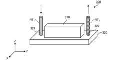
- FIG. 2 is a perspective view schematically showing the external configuration of the liquid droplet ejection head according to the embodiment.
- FIG. 3 is a plan view of the droplet ejection head according to the embodiment.
- FIG. 4 is a diagram schematically showing flow paths inside the droplet ejection head according to the embodiment.
- FIG. 5 is a diagram schematically showing a configuration example of an ejection unit according to the embodiment;
- FIG. 6 is a diagram schematically showing a circulation mechanism according to the embodiment;
- FIG. 7 is a flowchart showing the procedure of processing executed by the droplet ejection device according to the embodiment.
- FIG. 1 is a diagram schematically showing a configuration example of a droplet ejection device according to an embodiment.
- FIG. 2 is a perspective view schematically showing the external configuration of the liquid droplet ejection head according to the embodiment.
- FIG. 3 is a
- FIG. 8 is an explanatory diagram for explaining an adjustment mode of the circulation flow rate according to the embodiment.
- FIG. 9 is an explanatory diagram for explaining an adjustment mode of the circulation flow rate according to Modification 1 of the embodiment.
- FIG. 10 is an explanatory diagram for explaining an adjustment mode of the circulation flow rate according to Modification 2 of the embodiment.
- FIG. 11 is an explanatory diagram for explaining an adjustment mode of the circulation flow rate according to Modification 3 of the embodiment.
- FIG. 12 is an explanatory diagram for explaining an adjustment mode of the circulation flow rate according to Modification 4 of the embodiment.
- FIG. 13 is an explanatory diagram for explaining an adjustment mode of the circulation flow rate according to Modification 5 of the embodiment.
- FIG. 14 is a diagram schematically showing an example of the posture of the droplet ejection head according to Modification 5 of the embodiment.
- FIG. 15 is an explanatory diagram for explaining an adjustment mode of the circulation flow rate according to Modification 6 of the embodiment.
- FIG. 16 is an explanatory diagram for explaining an adjustment mode of the circulation flow rate according to Modification 7 of the embodiment.
- FIG. 17 is a diagram showing how pressure waves propagate according to Modification 7 of the embodiment.
- FIG. 18 is an explanatory diagram for explaining the internal structure of the droplet ejection head and the circulation mode of the coloring liquid according to Modification 8 of the embodiment.
- FIG. 19 is an explanatory diagram for explaining the internal structure of the droplet ejection head and the circulation mode of the coloring liquid according to Modification 8 of the embodiment.
- each embodiment can be appropriately combined within a range that does not contradict the processing content.
- the same parts are denoted by the same reference numerals, and overlapping descriptions are omitted.
- the droplet ejection device disclosed in the present application can be applied to various devices that eject droplets by the inkjet method, in addition to inkjet printers and inkjet plotters that use the inkjet recording method.
- FIG. 1 is a diagram schematically showing a configuration example of a droplet ejection device according to an embodiment.
- the droplet ejection device 1 includes a robot arm 100, a circulation mechanism 200, a droplet ejection head 300, and a control device 2.
- the robot arm 100 is assembled to a base 10 that is placed on a horizontal floor indoors or outdoors, for example.
- the robot arm 100 has an arm section 110 .
- the arm portion 110 is composed of a plurality of parts that are assembled so as to be bendable, stretchable, and rotatable.
- the arm unit 110 moves the droplet ejection head 300 mounted on the tip of the arm unit 110 and changes the position, posture, and angle of the droplet ejection head 300 in accordance with commands from the control unit 21, which will be described later. It can be carried out.
- the arm unit 110 illustrated in FIG. 1 is particularly limited to the configuration shown in FIG. not to be
- the robot arm 100 moves, for example, the circulation mechanism 200 and the droplet discharge head 300 mounted on the tip of the arm portion 110 along a predetermined rotation axis by the arm portion 110, thereby moving the robot arm 100 in the vertical direction (Z-axis direction). can be moved to As a result, the circulation mechanism 200 and the droplet ejection head 300, for example, as shown in FIG. can take a stance. Further, the robot arm 100 can rotate the circulation mechanism 200 and the liquid droplet ejection head 300 attached to the tip of the arm portion 110 around a predetermined rotation axis by the arm portion 110 . As a result, the circulation mechanism 200 and the liquid droplet ejection head 300 can, for example, exchange their longitudinal and lateral positions, or reverse their vertical positions.
- the circulation mechanism 200 is installed at the tip of the arm section 110 of the robot arm 100 .
- the circulation mechanism 200 supplies the coloring liquid to the droplet ejection heads 300 while controlling the circulation flow rate of the coloring liquid circulating between the droplet ejection heads 300 .
- the circulation mechanism 200 functions as a supply section that supplies the coloring liquid to the droplet ejection head 300 .
- the droplet ejection head 300 is attached to the circulation mechanism 200 installed at the tip of the arm portion 110 of the robot arm 100 .
- the droplet ejection head 300 functions as a droplet ejection section that ejects droplets of the coloring liquid onto the object 50 .
- the coloring liquid is a liquid that can be applied to the object 50 to color it. Also, the colored liquid is described by exemplifying a case where the viscosity is reduced as the shear rate increases, but the colored liquid may not be a pseudo-plastic fluid.
- the coloring liquid for example, ink or paint can be used.
- the control device 2 is, for example, a computer, and includes a control section 21 such as a processor and a storage section 22 such as a memory.
- the storage unit 22 stores programs for controlling various processes executed in the droplet ejection device 1 .
- the control unit 21 controls the operation of the droplet ejection device 1 by reading out and executing programs stored in the storage unit 22 .
- the program may be recorded in a computer-readable storage medium and installed in the storage unit 22 of the control device 2 from the storage medium.
- Examples of computer-readable storage media include hard disks (HD), flexible disks (FD), compact disks (CD), magnet optical disks (MO), and memory cards.
- the present application proposes a droplet ejection device 1 capable of suppressing ejection defects caused by stagnant substances remaining in the droplet ejection head 300 .
- FIG. 2 is a perspective view schematically showing the external configuration of the liquid droplet ejection head according to the embodiment.
- FIG. 3 is a plan view of the droplet ejection head according to the embodiment.
- FIG. 4 is a diagram schematically showing flow paths inside the droplet ejection head according to the embodiment.
- the droplet discharge head 300 has a housing including a box-shaped member 310 and a substantially flat plate-shaped member 320 .
- the housing of the droplet ejection head 300 has a supply port 321 for supplying the coloring liquid to the inside of the droplet ejection head 300 and a recovery port 322 for recovering the coloring liquid from the inside of the droplet ejection head 300 .
- the supply port 321 is connected to a first flow path RT1 for supplying the coloring liquid from the circulation mechanism 200 to the inside of the head.
- a second flow path RT 2 is connected to the recovery port 322 to return the coloring liquid recovered inside the head to the circulation mechanism 200 .
- the droplet ejection head 300 has a supply reservoir 301 , a supply manifold 302 , a recovery manifold 303 , a recovery reservoir 304 and an ejection unit 305 .
- the supply reservoir 301 has an elongated shape extending in the longitudinal direction (Y-axis direction) of the droplet discharge head 300 and is connected to the supply manifold 302 .
- the supply reservoir 301 has a channel inside. As shown in FIG. 4 , the coloring liquid supplied to the supply reservoir 301 through the first channel RT 1 and the supply port 321 and stored in the channel of the supply reservoir 301 is delivered to the supply manifold 302 .
- the supply manifold 302 has an elongated shape extending to the front of the recovery reservoir 304 in the lateral direction (X-axis direction) of the droplet ejection head 300 .
- the supply manifold 302 internally has a flow path that communicates with the flow path of the supply reservoir 301 and the discharge unit 305 . As shown in FIG. 4 , the coloring liquid delivered from the supply reservoir 301 to the supply manifold 302 is delivered from the supply manifold 302 to the ejection unit 305 .
- the recovery manifold 303 has an elongated shape extending in the lateral direction (X-axis direction) of the droplet ejection head 300 to the front of the supply reservoir 301 .
- the recovery manifold 303 internally has a channel that communicates with the channel of the recovery reservoir 304 and the discharge unit 305 . As shown in FIG. 4, the colored liquid that has not been discharged from the discharge unit 305 is sent to the collection manifold 303 .
- the recovery reservoir 304 has an elongated shape extending in the longitudinal direction (Y-axis direction) of the droplet discharge head 300 and is connected to the recovery manifold 303 .
- the recovery reservoir 304 has a channel inside. As shown in FIG. 4, the colored liquid sent from the recovery manifold 303 to the recovery reservoir 304 and stored in the flow path of the recovery reservoir 304 flows through the recovery port 322 and the second flow path RT2 into the tank 201 (see FIG. 6). ).
- FIG. 5 is a diagram schematically showing a configuration example of a discharge unit according to the embodiment.
- the discharge unit 305 has a nozzle 351 , a pressure chamber 352 and a displacement element 353 .
- the nozzle 351 is an ejection hole that opens to the ejection surface 30SF (see FIG. 1) of the droplet ejection head 300 .
- the pressurization chamber 352 is connected to the nozzle 351 .
- the pressure chamber 352 has a body portion 361 to which pressure is applied by the displacement element 353 and a descender 362 which is a flow path connecting the body portion 361 and the nozzle 351 .
- the pressurizing chamber 352 and the supply manifold 302 are connected via individual supply channels 354 .
- the colored liquid delivered from the supply manifold 302 to the discharge unit 305 is supplied to the pressurization chamber 352 through the individual supply channel 354 .
- the pressurization chamber 352 and the recovery manifold 303 are connected via individual recovery channels 355 .
- the colored liquid that has not been discharged from the nozzle 351 is recovered from the pressure chamber 352 to the recovery manifold 303 .
- the displacement element 353 is located on the side opposite to the descender 362 of the body portion 361 of the pressure chamber 352 .
- the displacement element 353 is an element that deforms according to a predetermined drive signal.
- the displacement element 353 functions as a pressurizing unit that applies pressure to the pressurizing chamber 352 to eject droplets of the colored liquid from the nozzle 351 . That is, by deforming the displacement element 353 , pressure (positive pressure and negative pressure) is applied to the pressure chamber 352 , and droplets of the colored liquid are discharged from the nozzle 351 .
- the displacement element 353 is electrically connected to the controller 2 and controlled by the controller 2 .
- the colored liquid is sucked from the supply manifold 302 by the negative pressure applied to the pressurizing chamber 352, and the sucked colored liquid is discharged from the nozzle 351 by the positive pressure applied to the pressurizing chamber 352. Discharge toward object 50 .
- FIG. 6 is a diagram schematically showing a circulation mechanism according to the embodiment.
- the circulation mechanism 200 includes a tank 201, a discharge pump 202, a suction pump 203, a first proportional valve 204, a second proportional valve 205, and a heater 206.
- the circulation mechanism 200 also includes a first pressure sensor 208 , a second pressure sensor 209 , a third pressure sensor 210 , a fourth pressure sensor 211 and a flow meter 212 .
- the circulation mechanism 200 also includes a first flow path RT- 1 and a second flow path RT -2 .
- the first flow path RT 1 is a flow path that communicates between the tank 201 and the droplet ejection head 300 and allows the colored liquid stored in the tank 201 to flow into the droplet ejection head 300 .
- the second flow path RT 2 is a flow path that communicates between the tank 201 and the droplet ejection head 300 and returns the colored liquid that has flowed into the droplet ejection head 300 back to the tank 201 .
- the colored liquid collected in the droplet ejection head 300 without being ejected from the droplet ejection head 300 to the outside is sent back to the tank 201 through the second flow path RT2 .
- the first flow path RT 1 and the second flow path RT 2 can be implemented, for example, by piping made of a predetermined material that does not interact with the components of the coloring liquid.
- the circulation mechanism 200 having such parts controls the circulation flow rate of the coloring liquid that circulates clockwise between the tank 201 and the droplet discharge head 300 as shown in FIG. .
- the tank 201 stores the coloring liquid supplied to the droplet ejection head 300 .
- the tank 201 functions as a storage section that stores the coloring liquid to be supplied to the droplet ejection head 300 .
- the ejection pump 202 supplies the colored liquid stored in the tank 201 to the droplet ejection head 300 through the first flow path RT1 .
- the ejection pump 202 generates positive pressure for sending the colored liquid stored in the tank 201 to the droplet ejection head 300 .
- the ejection pump 202 can, for example, deliver the colored liquid stored in the tank 201 to the droplet ejection head 300 at a preset constant supply pressure.
- the suction pump 203 feeds the colored liquid collected in the droplet discharge head 300 to the tank 201 through the second flow path RT2 .
- the suction pump 203 sucks the colored liquid collected in the droplet discharge head 300 and generates a negative pressure for sending it back to the tank 201 .
- the suction pump 203 can send the colored liquid sucked from the droplet ejection head 300 to the tank 201 at a preset constant recovery pressure, for example.
- the discharge pump 202 and the suction pump 203 can be implemented by rotary pumps such as gear pumps or positive displacement pumps such as diaphragm pumps.
- the first proportional valve 204 is interposed in the first flow path RT1 between the tank 201 and the droplet ejection head 300 and proportionally controls the flow rate of the coloring liquid supplied to the droplet ejection head 300 .
- the first proportional valve 204 can continuously change the flow cross-sectional area of the coloring liquid between 0% and 100%, and controls the flow rate of the coloring liquid to a desired flow rate.
- the first proportional valve 204 can reduce the supply flow rate when supplying the colored liquid to the droplet discharge head 300 by reducing the flow passage cross-sectional area of the colored liquid.
- the first proportional valve 204 can increase the supply flow rate when supplying the liquid to the droplet ejection head 300 by increasing the cross-sectional area of the liquid flow path.
- the second proportional valve 205 is interposed in the second flow path RT2 between the tank 201 and the droplet ejection head 300, and proportionally adjusts the flow rate of the coloring liquid supplied from the droplet ejection head 300 to the tank 201. Control. Like the first proportional valve 204, the second proportional valve 205 can continuously change the cross-sectional area of the liquid between 0% and 100%, and controls the flow rate of the coloring liquid to a desired flow rate. For example, the second proportional valve 205 can reduce the recovery flow rate when the colored liquid is recovered from the droplet ejection head 300 by reducing the cross-sectional area of the colored liquid flow path. On the other hand, the second proportional valve 205 can increase the recovery flow rate when the colored liquid is recovered from the droplet discharge head 300 by increasing the flow passage cross-sectional area of the colored liquid.
- the first proportional valve 204 and the second proportional valve 205 can be implemented by electromagnetic proportional switching valves or pneumatic proportional switching valves.
- the heater 206 is provided in the first flow path RT 1 or adjacent to the first flow path RT 1 and heats the coloring liquid flowing through the first flow path RT 1 .
- the first pressure sensor 208 measures the pressure of the colored liquid supplied from the tank 201 to the droplet ejection head 300 by the ejection pump 202 .
- the first pressure sensor 208 measures the pressure downstream of the discharge pump 202 in the circulation direction of the colored liquid in the circulation mechanism 200 .
- the first pressure sensor 208 sends the measurement result to the controller 21 .
- the second pressure sensor 209 measures the pressure of the colored liquid that is sucked from the droplet discharge head 300 by the suction pump 203 and fed to the tank 201 .
- the second pressure sensor 209 measures the pressure upstream of the suction pump 203 in the circulation direction of the coloring liquid in the circulation mechanism 200 .
- the second pressure sensor 209 sends the measurement result to the controller 21 .
- the third pressure sensor 210 functions as a first pressure measuring unit that measures the pressure of the colored liquid flowing between the first proportional valve 204 and the droplet ejection head 300 through the first flow path RT1 as the supply pressure. do.
- the third pressure sensor 210 sends the measurement result to the controller 21 .
- the fourth pressure sensor 211 functions as a second pressure measuring unit that measures the pressure of the colored liquid flowing between the second proportional valve 205 and the droplet ejection head 300 through the second flow path RT2 as the recovery pressure. do.
- the fourth pressure sensor 211 sends the measurement result to the controller 21 .
- the flow meter 212 measures the flow rate of the colored liquid supplied to the droplet ejection head 300 .
- the flow meter 212 sends the measurement results to the control section 21 .
- control unit 21 Based on the measurement result of the first pressure sensor 208 and the measurement result of the third pressure sensor 210, the control unit 21 adjusts the positive pressure applied to the coloring liquid when the discharge pump 202 delivers the coloring liquid so as to keep it constant. do.
- the control unit 21 controls the pressure of the colored liquid obtained from the measurement result of the first pressure sensor 208 to be 1.2 to 3 times higher than the pressure of the colored liquid obtained from the measurement result of the third pressure sensor 210.
- the positive pressure of the discharge pump 202 is adjusted so as to maintain a moderately large pressure.
- the control unit 21 adjusts the negative pressure applied to the coloring liquid when the suction pump 203 sucks the coloring liquid so as to keep it constant. do.
- the controller 21 controls the pressure of the colored liquid obtained from the measurement result of the second pressure sensor 209 to be 1.2 to 3 times higher than the pressure of the colored liquid obtained from the measurement result of the fourth pressure sensor 211.
- the negative pressure of the suction pump 203 is adjusted so as to maintain a moderately low pressure.
- the control unit 21 adjusts the pressure difference between the positive pressure applied to the colored liquid by the discharge pump 202 and the negative pressure applied to the colored liquid by the suction pump 203 so as to maintain a constant pressure difference between the tank 201 and the liquid.
- the colored liquid is circulated between the droplet ejection heads 300 .
- FIG. 7 is a flowchart showing the procedure of processing executed by the droplet ejection device according to the embodiment. Note that each process shown in FIG. 7 is executed under the control of the control unit 21 .
- step S101 an ejection process of ejecting droplets of a colored liquid from the droplet ejection head 300 is performed (step S101).
- the control unit 21 applies pressure to the pressure chamber 352 by controlling the displacement element 353 provided in the droplet ejection head 300 to eject the colored liquid from the nozzle 351 toward the object 50 .
- the cumulative processing period during which the ejection process is performed is referred to as an "ejection period.”
- control unit 21 controls the ejection pump 202 and the suction pump 203 to start circulation of the colored liquid between the tank 201 and the droplet ejection head 300 before starting the ejection process.
- step S102 it is determined whether or not the maintenance period for performing maintenance processing of the droplet ejection head 300 has arrived. The determination in step S102 is made, for example, based on whether or not the ejection period has exceeded a predetermined period. If the maintenance period has not yet arrived (step S102; No), the process returns to step S101, and the ejection process is continued.
- step S103 maintenance processing for the droplet ejection head 300 is performed (step S103).
- the control unit 21 controls the circulation mechanism 200 to adjust the circulation flow rate of the coloring liquid circulating between the circulation mechanism 200 and the droplet ejection head 300 .
- a mode of adjusting the circulation flow rate of the coloring liquid circulating between the circulation mechanism 200 and the droplet ejection head 300 will be described later.
- the control unit 21 ends a series of processes in the droplet ejection device 1 .
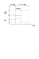
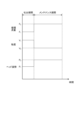
- FIG. 8 is an explanatory diagram for explaining an adjustment mode of the circulation flow rate according to the embodiment.
- FIG. 8 shows temporal changes in the "circulation flow rate” and "viscosity” during the discharge period and the maintenance period.
- “Circulation flow rate” refers to the circulation flow rate of the coloring liquid circulating between the circulation mechanism 200 and the droplet ejection head 300
- “viscosity” refers to the viscosity of the coloring liquid supplied from the circulation mechanism 200 to the droplet ejection head 300 . refers to viscosity.
- the control unit 21 controls the circulation mechanism 200 during the maintenance period after the ejection period to increase the circulation flow rate of the coloring liquid more than the circulation flow rate of the coloring liquid during the ejection period.
- the colored liquid is a pseudoplastic fluid whose viscosity decreases as the shear rate increases. The viscosity of the coloring liquid is reduced. Therefore, by increasing the circulation flow rate of the colored liquid during the maintenance period, the control section 21 can supply the droplet discharge head 300 with a colored liquid having a lower viscosity than the colored liquid during the discharge period.
- control unit 21 changes the flow passage cross-sectional area of the first proportional valve 204 and the second proportional valve 205 in the circulation mechanism 200 to change the supply flow rate and recovery flow rate of the coloring liquid, thereby changing the circulation flow rate during the discharge period. is increased from the circulation flow rate F 1 of the coloring liquid to a circulation flow rate F 2 (>F 1 ).
- the control unit 21 can reduce the viscosity of the colored liquid supplied to the droplet ejection head 300 during the maintenance period from the viscosity V 1 of the colored liquid during the ejection period to the viscosity V 2 ( ⁇ V 1 ). .
- the circulating flow rate of the colored liquid is increased more than the circulated flow rate of the colored liquid during the ejection period, thereby lowering the viscosity of the colored liquid compared to the viscosity of the colored liquid during the ejection period.
- the droplets can be ejected by reducing the viscosity of the colored liquid. It is possible to make it easier to peel off the accumulated matter from the inner wall of the flow path in the head 300 . As a result, the accumulated matter is smoothly discharged to the outside of the droplet discharge head 300 , so that it is possible to prevent the accumulated matter from obstructing the flow of the coloring liquid in the flow path inside the droplet discharge head 300 . As a result, it is possible to suppress ejection defects caused by residual matter remaining in the droplet ejection head 300 .
- the circulating flow rate of the colored liquid is increased during the entire maintenance period more than the circulating flow rate of the colored liquid during the discharge period.
- the circulation flow rate of the coloring liquid may be increased.
- the control unit 21 may control the circulation mechanism 200 during at least part of the maintenance period to increase the circulation flow rate of the coloring liquid more than that during the ejection period.
- FIG. 9 is an explanatory diagram for explaining the adjustment mode of the circulation flow rate according to Modification 1 of the embodiment.
- control unit 21 controls the circulation mechanism 200 to change the circulation flow rate of the coloring liquid between a first period and a second period following the first period included in the maintenance period. . Thereby, the control unit 21 can change the viscosity of the coloring liquid between the first period and the second period following the first period included in the maintenance period.
- control unit 21 changes the flow passage cross-sectional area of the first proportional valve 204 and the second proportional valve 205 in the circulation mechanism 200 to change the supply flow rate and recovery flow rate of the coloring liquid, thereby reducing the circulation flow rate to the first During the period, the circulation flow rate is set to F 2 , and during the second period, the circulation flow rate is set to F 3 ( ⁇ F 2 ). As a result, the control unit 21 can set the viscosity of the colored liquid supplied to the droplet ejection head 300 to V 2 during the first period and to V 3 (>V 2 ) during the second period. can.
- Modification 1 by changing the circulation flow rate of the colored liquid, it is possible to supply the liquid droplet discharge head 300 with a relatively low-viscosity colored liquid and a relatively high-viscosity colored liquid.
- the relatively low-viscosity colored liquid peels off the remaining matter from the inner wall of the flow path in the droplet discharge head 300, and the relatively high-viscosity colored liquid removes the remaining matter from the inside of the droplet discharge head 300. can be washed away.
- the circulation flow rate of the coloring liquid is changed from a relatively high flow rate (eg, circulation flow rate F 2 ) to a relatively low flow rate (eg, circulation flow rate F 3 ).
- the relatively high-viscosity colored liquid can be supplied to the droplet-discharging head 300 after the relatively low-viscosity colored liquid is supplied to the droplet-discharging head 300 . That is, after the staying matter is peeled off from the inner wall of the flow path in the droplet discharge head 300 by the relatively low-viscosity colored liquid, it remains in the droplet-discharge head 300 by the relatively high-viscosity colored liquid. Remaining matter can be washed away. As a result, according to Modification 1, the remaining matter can be more smoothly discharged to the outside of the droplet discharge head 300 .
- FIG. 10 is an explanatory diagram for explaining the adjustment mode of the circulation flow rate according to Modification 2 of the embodiment.
- the circulation flow rate of the coloring liquid is changed from a relatively high flow rate to a relatively low flow rate. Change to a higher flow rate.
- control unit 21 controls the circulation mechanism 200 to set the circulation flow rate to F2 in the first period and to F3 (> F2 ) in the second period. do.
- control unit 21 can set the viscosity of the colored liquid supplied to the droplet ejection head 300 to V 2 during the first period and to V 3 ( ⁇ V 2 ) during the second period. can.
- the circulation flow rate of the coloring liquid is changed from a relatively low flow rate (for example, circulation flow rate F 2 ) to a relatively high flow rate (for example, circulation flow rate F 3 ).
- the relatively low-viscosity colored liquid can be supplied to the droplet ejection head 300 after the relatively high-viscosity colored liquid is supplied to the droplet ejection head 300 . That is, after the staying matter remaining in the droplet ejection head 300 is washed away by the relatively high-viscosity coloring liquid, the remaining matter is removed from the flow path inside the droplet ejection head 300 by the relatively low-viscosity coloring liquid. It can be transported downstream at high speed. As a result, according to Modification 1, the remaining matter can be more smoothly discharged to the outside of the droplet discharge head 300 .
- control unit 21 may control the circulation mechanism 200 to repeat the process of changing the circulation flow rate of the coloring liquid a plurality of times during the maintenance period.
- FIG. 11 is an explanatory diagram for explaining the adjustment mode of the circulation flow rate according to Modification 3 of the embodiment.
- a solidified substance of the coloring liquid (hereinafter referred to as a “solidified substance” as appropriate) stays as a stagnant substance.
- the colored liquid contains a dissolving component capable of dissolving the solidified substance of the colored liquid, and the solidified substance remaining in the droplet ejection head 300 is dissolved by the dissolving component.
- control unit 21 controls the circulation mechanism 200 during the maintenance period to circulate the coloring liquid for a predetermined time period for the solidified matter remaining in the droplet discharge head 300 to dissolve in the dissolved component. is stopped, the circulation flow rate of the coloring liquid is increased.
- control unit 21 changes the cross-sectional area of the first proportional valve 204 and the second proportional valve 205 in the circulation mechanism 200 to 0 to stop the circulation of the coloring liquid for a predetermined period of time, thereby reducing the circulation flow rate to 0. and After a predetermined period of time, the control unit 21 increases the cross-sectional area of the flow passages of the first proportional valve 204 and the second proportional valve 205 in the circulation mechanism 200 to be greater than 0, thereby reducing the circulation flow rate to the level of the circulation of the colored liquid during the ejection period. Increase the circulation flow rate F2 , which is higher than the flow rate F1 .
- control unit 21 can reduce the viscosity of the colored liquid supplied to the droplet ejection head 300 to the viscosity V2 , which is lower than the viscosity V1 of the colored liquid during the ejection period, after the predetermined time has elapsed.
- the circulation of the coloring liquid is stopped for a predetermined time before increasing the circulation flow rate of the coloring liquid.
- the solidified matter remaining in the droplet ejection head 300 is dissolved in the dissolved component contained in the coloring liquid, and the solidified matter after dissolution is dissolved in the flow path in the droplet ejection head 300 by the coloring liquid. It can be transported downstream at high speed. As a result, according to Modification 3, the solidified colored liquid can be more smoothly discharged to the outside of the droplet discharge head 300 .
- FIG. 12 is an explanatory diagram for explaining the adjustment mode of the circulation flow rate according to Modification 4 of the embodiment.
- FIG. 12 shows temporal changes in the "head posture" during the ejection period and the maintenance period.
- “Head attitude” refers to the attitude of the droplet ejection head 300 mounted on the robot arm 100 .
- control unit 21 controls the circulation mechanism 200 to increase the circulation flow rate of the coloring liquid, and controls the robot arm 100 to eject droplets.
- the posture of the head 300 is changed.
- control unit 21 changes the flow passage cross-sectional area of the first proportional valve 204 and the second proportional valve 205 in the circulation mechanism 200 to change the supply flow rate and recovery flow rate of the coloring liquid, thereby changing the circulation flow rate during the discharge period. is increased from the circulation flow rate F 1 of the coloring liquid to a circulation flow rate F 2 (>F 1 ).
- the control unit 21 can reduce the viscosity of the colored liquid supplied to the droplet ejection head 300 during the maintenance period from the viscosity V 1 of the colored liquid during the ejection period to the viscosity V 2 ( ⁇ V 1 ). .
- control unit 21 maintains the posture of the droplet ejection head 300 at a constant posture P1 during the ejection period, and operates the arm unit 110 of the robot arm 100 during the maintenance period to eject droplets.
- the posture of the head 300 is sequentially changed to a plurality of arbitrary postures.
- the inclination of the droplet ejection head 300 with respect to the direction of gravity can be changed by changing the attitude of the droplet ejection head 300 during the maintenance period after the ejection period.
- the solidified colored liquid remaining in the droplet discharge head 300 tends to move in the direction of gravity under the force of gravity. Bubbles staying in the droplet discharge head 300 tend to move in the direction opposite to the direction of gravity due to buoyancy. Therefore, in Modified Example 4, by changing the attitude of the droplet discharge head 300, solidified substances of the colored liquid, bubbles, and the like staying in the droplet discharge head 300 are moved in the direction of gravity and in the direction of gravity. It can be effectively moved in the opposite direction. As a result, in Modification 4, the movement of the accumulated matter in the direction of gravity and in the direction opposite to the direction of gravity can be promoted, so that the accumulated matter can be smoothly discharged to the outside of the droplet discharge head 300 . can be done.
- the attitude of the droplet ejection head 300 is changed at the timing of increasing the circulation flow rate of the coloring liquid.
- the timing for starting the attitude change of the droplet ejection head 300 is matched with the timing for increasing the circulation flow rate of the coloring liquid.
- the posture of the droplet ejection head 300 is changed during the entire maintenance period. You can change your posture.
- the control unit 21 controls the circulation mechanism 200 to increase the circulation flow rate of the coloring liquid, and controls the robot arm 100 to increase the liquid droplet discharge head 300. You can change your posture.
- FIG. 13 is an explanatory diagram for explaining the adjustment mode of the circulation flow rate according to Modification 5 of the embodiment.
- FIG. 14 is a diagram schematically showing an example of the posture of the droplet ejection head according to Modification 5 of the embodiment. Modification 5 relates to a variation in attitude change of the droplet discharge head 300 in Modification 4. FIG.
- control unit 21 controls the robot arm 100 during the maintenance period after the ejection period so that the posture of the droplet ejection head 300 is adjusted so that the recovery port 322 is closer to the supply port 321 than the recovery port 321 is. Change to posture P2 , which is higher.
- the posture of the droplet ejection head 300 is changed to a posture in which the recovery port 322 is higher than the supply port 321.
- the height position may be reversed. That is, the controller 21 may change the posture of the droplet discharge head 300 to a posture in which the supply port 321 is higher than the recovery port 322 .
- the solidified colored liquid remaining in the droplet discharge head 300 can be efficiently moved in the direction of gravity.
- the movement of the solidified colored liquid in the direction from the supply port 321 to the recovery port 322 can be promoted, so that the solidified colored liquid can be smoothly discharged from the recovery port 322 to the outside of the droplet ejection head 300 . can do.
- FIG. 15 is an explanatory diagram for explaining the adjustment mode of the circulation flow rate according to Modification 6 of the embodiment.
- Modification 6 relates to a variation of the attitude change of the droplet ejection head 300 in Modification 5.
- FIG. 15 is an explanatory diagram for explaining the adjustment mode of the circulation flow rate according to Modification 6 of the embodiment.
- Modification 6 relates to a variation of the attitude change of the droplet ejection head 300 in Modification 5.
- FIG. 15 is an explanatory diagram for explaining the adjustment mode of the circulation flow rate according to Modification 6 of the embodiment.
- Modification 6 relates to a variation of the attitude change of the droplet ejection head 300 in Modification 5.
- FIG. 15 is an explanatory diagram for explaining the adjustment mode of the circulation flow rate according to Modification 6 of the embodiment.
- Modification 6 relates to a variation of the attitude change of the droplet ejection head 300 in Modification 5.
- FIG. 15 is an explanatory diagram for explaining the adjustment mode of the circulation flow rate according to Mod
- the control unit 21 sets the attitude of the droplet ejection head 300 to P2, in which the recovery port 322 is higher than the supply port 321, and to P2 , in which the supply port 321 is recovered.
- the posture is changed between posture P3 where the mouth 322 is higher.
- FIG. 16 is an explanatory diagram for explaining the adjustment mode of the circulation flow rate according to Modification 7 of the embodiment.
- FIG. 16 shows temporal changes in the "applied pressure” during the ejection period and the maintenance period.
- “Applied pressure” refers to the pressure applied from the displacement element 353 to the pressure chamber 352 in the droplet ejection head 300 .
- control unit 21 controls the circulation mechanism 200 during the maintenance period after the discharge period to increase the circulation flow rate of the coloring liquid and apply pressure to the pressure chamber 352 by the displacement element 353 .
- control unit 21 applies pressure C1 to the pressurizing chamber 352 by the displacement element 353 during the ejection period, and increases the circulation flow rate to F2 (> F1 ) during the maintenance period. maintains the application of pressure from to the pressurizing chamber 352 .
- control unit 21 can reduce the viscosity of the colored liquid supplied to the droplet ejection head 300 during the maintenance period from the viscosity V 1 of the colored liquid during the ejection period to the viscosity V 2 ( ⁇ V 1 ). .
- the viscosity of the colored liquid supplied to the droplet ejection head 300 is reduced by applying pressure to the pressurizing chamber 352 while increasing the circulation flow rate of the colored liquid.
- pressure waves can be generated in the pressurizing chamber 352 .
- the viscosity of the coloring liquid flowing through the pressure chamber 352 and the supply manifold 302 and recovery manifold 303 (hereinafter collectively referred to as "manifolds") connected to the pressure chamber 352 are reduced. ) can be made smaller.
- the pressure wave PW generated in the pressure chamber 352 is generated in the pressure chamber 352 as shown in FIG. Not only that, but it also becomes easier to propagate to the manifold.
- FIG. 17 is a diagram showing how pressure waves propagate according to Modification 7 of the embodiment. In this way, the pressure wave PW generated in the pressurizing chamber 352 propagates to the manifold, so that the accumulated matter remaining in the manifold can be intensively removed by the pressure wave PW.
- both the pressure applied to the pressurizing chamber 352 during the discharge period and the pressure applied to the pressurizing chamber 352 during the maintenance period are pressure C1 .
- the pressure applied to the pressurizing chamber 352 during the maintenance period may be lower than the pressure applied to the pressurizing chamber 352 during the ejection period (that is, the pressure for ejecting the colored liquid from the nozzle 351). .
- the flow path resistance of the individual recovery channel 355 connecting the pressure chamber 352 of the ejection unit 305 and the recovery manifold 303 causes the pressure chamber 352 and the supply manifold 302 to be separated. It is smaller than the channel resistance of the connecting individual supply channel 354 .
- the channel resistance of the individual recovery channel 355 is made smaller than the channel resistance of the individual supply channel 354. can do.
- the control unit 21 controls the circulation mechanism 200 to circulate the coloring liquid from the recovery port 322 toward the supply port 321 during the maintenance period after the ejection period. For example, during a first period included in the maintenance period, the controller 21 controls the circulation mechanism 200 to circulate the coloring liquid from the supply port 321 toward the recovery port 322 as shown in FIG. Then, in a second period following the first period included in the maintenance period, the control unit 21 controls the circulation mechanism 200 to reverse the flow direction of the coloring liquid, as shown in FIG. The coloring liquid is circulated from the port 322 toward the supply port 321 .
- the direction of circulation (flow direction) of the coloring liquid is changed from the direction from the supply port 321 to the recovery port 322 to the direction from the recovery port 322 to the supply port 321 .
- the colored liquid flows through the recovery reservoir 304, recovery manifold 303, individual recovery channel 355, discharge unit 305, individual supply channel 354, supply manifold 302, and supply reservoir 301 in this order.
- the channel resistance of the individual recovery channel 355 is smaller than the channel resistance of the individual supply channel 354 .
- the shear rate of the colored liquid increases in the individual recovery channel 355 , the viscosity of the colored liquid decreases, and the colored liquid with reduced viscosity flows through the discharge unit 305 and the individual supply channel 354 to the supply manifold 302 . It flows in and reaches the tip portion 302 a of the supply manifold 302 .
- the relatively high-viscosity colored liquid staying in the tip portion 302a of the supply manifold 302 can be replaced with the relatively low-viscosity colored liquid.
- the circulation mechanism 200 supplies the colored liquid to the droplet ejection head 300
- the supply section that supplies the colored liquid to the droplet ejection head 300 is not limited to the circulation mechanism 200
- the supply unit includes a plurality of liquid supply sources that respectively supply a plurality of colored liquids with different viscosities, a supply channel that connects the plurality of liquid supply sources and the droplet ejection head 300, and a supply channel for each liquid supply source. It may be a liquid supply mechanism including an on-off valve provided in the passage.
- the control unit 21 controls the opening/closing valve of the liquid supply mechanism during at least a part of the maintenance period after the ejection period, so that the color liquid is more than the colored liquid during the ejection period.
- a colored liquid having a low viscosity may be supplied to the droplet ejection head 300 .
- the colored liquid need not be a pseudoplastic fluid.
- the droplet discharge head 300 should at least have a nozzle 351, a pressure chamber 352 connected to the nozzle 351, and an actuator (displacement element 353) that applies pressure to the pressure chamber 352. good.
- the droplet ejection device (eg, droplet ejection device 1) according to the embodiment includes a droplet ejection head (eg, droplet ejection head 300) and a supply unit (eg, circulation mechanism 200). , and a control unit (for example, control unit 21).
- the droplet ejection head ejects droplets of the coloring liquid.
- the supply unit supplies the coloring liquid to the droplet ejection head.
- the control section controls each section.
- the control unit controls the supply unit during at least a part of the maintenance period after the ejection period for ejecting droplets of the colored liquid from the droplet ejection head so that the viscosity of the colored liquid is higher than that during the ejection period.
- a colored liquid having a low viscosity is supplied to the droplet ejection head.
- the colored liquid may be a pseudoplastic fluid whose viscosity decreases as the shear rate increases.
- the supply unit may be a circulation mechanism (for example, the circulation mechanism 200) that supplies the coloring liquid to the droplet ejection head while controlling the circulation flow rate of the coloring liquid that circulates between the droplet ejection head. Further, the control unit may control the circulation mechanism during at least a part of the maintenance period to increase the circulation flow rate of the coloring liquid more than the circulation flow rate of the coloring liquid during the ejection period.
- the circulating flow rate of the colored liquid is increased more than the circulated flow rate of the colored liquid during the ejection period, thereby lowering the viscosity of the colored liquid compared to the viscosity of the colored liquid during the ejection period.
- the control unit may control the circulation mechanism to change the circulation flow rate of the coloring liquid between a first period and a second period following the first period included in the maintenance period.
- the control unit may control the circulation mechanism to change the circulation flow rate of the coloring liquid between a first period and a second period following the first period included in the maintenance period.
- the control unit may control the circulation mechanism to set the circulation flow rate of the coloring liquid to a first flow rate during the first period and to a second flow rate that is lower than the first flow rate during the second period.
- the control unit may control the circulation mechanism to set the circulation flow rate of the coloring liquid to a first flow rate during the first period and to a second flow rate higher than the first flow rate during the second period.
- the control unit may control the circulation mechanism to stop the circulation of the coloring liquid for a predetermined time, and then increase the circulation flow rate of the coloring liquid.
- the control unit may control the circulation mechanism to stop the circulation of the coloring liquid for a predetermined time, and then increase the circulation flow rate of the coloring liquid.
- the droplet ejection device may further include a robot arm (for example, robot arm 100).
- the robot arm mounts the liquid droplet ejection head so that its posture can be changed.
- the control unit controls the circulation mechanism to increase the circulation flow rate of the coloring liquid, and controls the robot arm to change the attitude of the droplet discharge head.
- the controller may change the attitude of the droplet discharge head at the timing of increasing the circulation flow rate of the coloring liquid.
- the droplet ejection head has a supply port (for example, supply port 321) for supplying colored liquid to the inside of the droplet ejection head and a recovery port (for example, collection port 322). Further, the control unit may change the attitude of the droplet ejection head so that one of the supply port and the recovery port is higher than the other. As a result, according to the droplet ejection device according to the embodiment, solidified matter or air bubbles of the colored liquid can be smoothly discharged from the recovery port to the outside of the droplet ejection head.
- the controller changes the posture of the droplet ejection head between a posture in which one of the supply port and the recovery port is higher than the other and a posture in which the other of the supply port and the recovery port is higher than the other. good too.
- the droplet ejection head may have an ejection unit (eg, ejection unit 305), a supply manifold (eg, supply manifold 302), and a recovery manifold (eg, recovery manifold 303).
- the discharge unit may include a nozzle (eg, nozzle 351), a pressure chamber (eg, pressure chamber 352), and a pressure member (eg, displacement element 353).
- a pressurized chamber is connected to the nozzle.
- the pressurizing section applies pressure to the pressurizing chamber to eject droplets of the colored liquid from the nozzle.
- the supply manifold is connected to the pressurization chamber and supplies the coloring liquid to the pressurization chamber.
- the recovery manifold is connected to the pressurization chamber and recovers the coloring liquid from the pressurization chamber.
- the control unit may control the circulation mechanism to increase the circulation flow rate of the coloring liquid during at least part of the maintenance period, and apply pressure to the pressurization chamber by the pressurization unit.
- the droplet ejection head may have an ejection unit (eg, ejection unit 305), a supply manifold (eg, supply manifold 302), and a recovery manifold (eg, recovery manifold 303).
- the discharge unit may include a nozzle (eg, nozzle 351), a pressure chamber (eg, pressure chamber 352), and a pressure member (eg, displacement element 353).
- a pressurized chamber is connected to the nozzle.
- the pressurizing section applies pressure to the pressurizing chamber to eject droplets of the colored liquid from the nozzle.
- the supply manifold is connected to the pressurizing chamber, and supplies the coloring liquid supplied from the supply port (for example, the supply port 321) side of the droplet ejection head to the pressurizing chamber.
- the recovery manifold is connected to the pressurization chamber, recovers the colored liquid from the pressurization chamber, and delivers it to the recovery port (for example, the recovery port 322) side of the droplet ejection head.
- the pressure chamber and the supply manifold may be connected via individual supply channels (for example, individual supply channels 354).
- the pressurized chamber and the recovery manifold may be connected via an individual recovery channel (for example, individual recovery channel 355).
- the channel resistance of the individual recovery channel may be smaller than the channel resistance of the individual supply channel.
- control unit may control the circulation mechanism during at least part of the maintenance period to circulate the coloring liquid from the recovery port toward the supply port.
Landscapes
- Chemical & Material Sciences (AREA)
- Analytical Chemistry (AREA)
- Physics & Mathematics (AREA)
- Fluid Mechanics (AREA)
- Engineering & Computer Science (AREA)
- Robotics (AREA)
- Ink Jet (AREA)
- Coating Apparatus (AREA)
Priority Applications (6)
| Application Number | Priority Date | Filing Date | Title |
|---|---|---|---|
| US18/722,592 US20250153484A1 (en) | 2021-12-23 | 2022-12-23 | Droplet discharge device and maintenance method |
| EP22911399.8A EP4454885A4 (en) | 2021-12-23 | 2022-12-23 | DROPLET RELEASE DEVICE AND MAINTENANCE METHOD |
| JP2023569568A JP7447365B2 (ja) | 2021-12-23 | 2022-12-23 | 液滴吐出装置及びメンテナンス方法 |
| CN202280084343.3A CN118414252A (zh) | 2021-12-23 | 2022-12-23 | 液滴喷出装置及维护方法 |
| JP2024028117A JP7707341B2 (ja) | 2021-12-23 | 2024-02-28 | 液滴吐出装置及びメンテナンス方法 |
| JP2025111587A JP2025126357A (ja) | 2021-12-23 | 2025-07-01 | 液滴吐出装置及びメンテナンス方法 |
Applications Claiming Priority (2)
| Application Number | Priority Date | Filing Date | Title |
|---|---|---|---|
| JP2021-209223 | 2021-12-23 | ||
| JP2021209223 | 2021-12-23 |
Publications (1)
| Publication Number | Publication Date |
|---|---|
| WO2023120698A1 true WO2023120698A1 (ja) | 2023-06-29 |
Family
ID=86902840
Family Applications (1)
| Application Number | Title | Priority Date | Filing Date |
|---|---|---|---|
| PCT/JP2022/047599 Ceased WO2023120698A1 (ja) | 2021-12-23 | 2022-12-23 | 液滴吐出装置及びメンテナンス方法 |
Country Status (5)
| Country | Link |
|---|---|
| US (1) | US20250153484A1 (https=) |
| EP (1) | EP4454885A4 (https=) |
| JP (3) | JP7447365B2 (https=) |
| CN (1) | CN118414252A (https=) |
| WO (1) | WO2023120698A1 (https=) |
Cited By (1)
| Publication number | Priority date | Publication date | Assignee | Title |
|---|---|---|---|---|
| JP7761741B1 (ja) * | 2024-11-27 | 2025-10-28 | アーベーベー・シュバイツ・アーゲー | 塗料温度調節装置 |
Citations (6)
| Publication number | Priority date | Publication date | Assignee | Title |
|---|---|---|---|---|
| JP3629926B2 (ja) | 1997-11-21 | 2005-03-16 | 富士ゼロックス株式会社 | インクジェットヘッド洗浄液およびその製造方法ならびにそれを用いたインクジェットヘッドの洗浄方法 |
| JP2013180527A (ja) * | 2012-03-02 | 2013-09-12 | Seiren Co Ltd | インク置換方法 |
| JP2015178574A (ja) * | 2014-03-19 | 2015-10-08 | セイコーエプソン株式会社 | メンテナンス液及びメンテナンス方法 |
| JP2016179615A (ja) * | 2015-03-24 | 2016-10-13 | ブラザー工業株式会社 | 洗浄液、洗浄液とインクセットのキット、インクジェット記録装置及びインクタンクの洗浄方法 |
| JP2018024873A (ja) * | 2016-08-09 | 2018-02-15 | 船井電機株式会社 | インク組成物、プリンタ、およびインク組成物の吐出方法 |
| JP6889810B1 (ja) * | 2020-03-30 | 2021-06-18 | 京セラ株式会社 | 液体吐出装置及び液体吐出方法 |
Family Cites Families (14)
| Publication number | Priority date | Publication date | Assignee | Title |
|---|---|---|---|---|
| JP2008149594A (ja) * | 2006-12-19 | 2008-07-03 | Toshiba Tec Corp | インクジェット記録装置 |
| DE102010004496B4 (de) | 2010-01-12 | 2020-06-18 | Hermann Müller | Verfahren zum Betrieb einer Vorrichtung zum Beschichten und/oder Bedrucken eines Werkstückes |
| JP5664001B2 (ja) | 2010-07-30 | 2015-02-04 | ブラザー工業株式会社 | 液体吐出装置 |
| JP5569224B2 (ja) | 2010-07-30 | 2014-08-13 | ブラザー工業株式会社 | 液体吐出装置 |
| JP2014144536A (ja) * | 2013-01-25 | 2014-08-14 | Fuji Xerox Co Ltd | 液滴吐出ヘッド及び液滴吐出装置 |
| JP6519470B2 (ja) * | 2013-07-02 | 2019-05-29 | コニカミノルタ株式会社 | インクジェットプリンタおよび画像形成方法 |
| JP2017196738A (ja) * | 2016-04-25 | 2017-11-02 | 株式会社リコー | 充填液交換装置 |
| US10293601B2 (en) | 2017-07-11 | 2019-05-21 | The Boeing Company | Automated controls for contoured surface inkjet printing |
| JP7256274B2 (ja) * | 2019-08-30 | 2023-04-11 | 京セラ株式会社 | 循環装置 |
| JP7202276B2 (ja) | 2019-09-30 | 2023-01-11 | 東レエンジニアリング株式会社 | インクジェット塗布装置 |
| WO2021085501A1 (ja) * | 2019-10-28 | 2021-05-06 | 京セラ株式会社 | 塗装装置および払拭方法 |
| JP7415454B2 (ja) | 2019-11-07 | 2024-01-17 | コニカミノルタ株式会社 | インクジェット記録装置及びインク送液制御方法 |
| WO2021199451A1 (ja) | 2020-03-30 | 2021-10-07 | 京セラ株式会社 | 液体吐出装置及び液体吐出方法 |
| CN112721457B (zh) | 2020-12-23 | 2022-04-22 | 惠州市迪日科技发展有限公司 | 循环供墨系统、喷墨打印装置以及喷墨打印设备 |
-
2022
- 2022-12-23 CN CN202280084343.3A patent/CN118414252A/zh active Pending
- 2022-12-23 EP EP22911399.8A patent/EP4454885A4/en active Pending
- 2022-12-23 JP JP2023569568A patent/JP7447365B2/ja active Active
- 2022-12-23 WO PCT/JP2022/047599 patent/WO2023120698A1/ja not_active Ceased
- 2022-12-23 US US18/722,592 patent/US20250153484A1/en active Pending
-
2024
- 2024-02-28 JP JP2024028117A patent/JP7707341B2/ja active Active
-
2025
- 2025-07-01 JP JP2025111587A patent/JP2025126357A/ja active Pending
Patent Citations (6)
| Publication number | Priority date | Publication date | Assignee | Title |
|---|---|---|---|---|
| JP3629926B2 (ja) | 1997-11-21 | 2005-03-16 | 富士ゼロックス株式会社 | インクジェットヘッド洗浄液およびその製造方法ならびにそれを用いたインクジェットヘッドの洗浄方法 |
| JP2013180527A (ja) * | 2012-03-02 | 2013-09-12 | Seiren Co Ltd | インク置換方法 |
| JP2015178574A (ja) * | 2014-03-19 | 2015-10-08 | セイコーエプソン株式会社 | メンテナンス液及びメンテナンス方法 |
| JP2016179615A (ja) * | 2015-03-24 | 2016-10-13 | ブラザー工業株式会社 | 洗浄液、洗浄液とインクセットのキット、インクジェット記録装置及びインクタンクの洗浄方法 |
| JP2018024873A (ja) * | 2016-08-09 | 2018-02-15 | 船井電機株式会社 | インク組成物、プリンタ、およびインク組成物の吐出方法 |
| JP6889810B1 (ja) * | 2020-03-30 | 2021-06-18 | 京セラ株式会社 | 液体吐出装置及び液体吐出方法 |
Non-Patent Citations (1)
| Title |
|---|
| See also references of EP4454885A4 |
Cited By (1)
| Publication number | Priority date | Publication date | Assignee | Title |
|---|---|---|---|---|
| JP7761741B1 (ja) * | 2024-11-27 | 2025-10-28 | アーベーベー・シュバイツ・アーゲー | 塗料温度調節装置 |
Also Published As
| Publication number | Publication date |
|---|---|
| CN118414252A (zh) | 2024-07-30 |
| US20250153484A1 (en) | 2025-05-15 |
| JP7447365B2 (ja) | 2024-03-11 |
| EP4454885A4 (en) | 2026-01-07 |
| JPWO2023120698A1 (https=) | 2023-06-29 |
| JP2024055933A (ja) | 2024-04-19 |
| JP2025126357A (ja) | 2025-08-28 |
| JP7707341B2 (ja) | 2025-07-14 |
| EP4454885A1 (en) | 2024-10-30 |
Similar Documents
| Publication | Publication Date | Title |
|---|---|---|
| US8449087B2 (en) | Liquid circulating apparatus, computer-readable medium, and liquid discharging apparatus | |
| JP5600910B2 (ja) | 液体噴射装置及び液体噴射装置における液体噴射ヘッドのクリーニング方法 | |
| JP5515523B2 (ja) | 液体噴射装置 | |
| CN104890369B (zh) | 液体喷射装置及其控制方法 | |
| JP4895723B2 (ja) | 液体吐出装置および液体吐出面の清掃方法 | |
| US8403439B2 (en) | Flow rate control device, liquid-droplet ejecting device, and computer readable medium | |
| JP5261340B2 (ja) | 液滴吐出装置 | |
| JP2012152972A (ja) | 流路ユニット、および、流路ユニットを備える画像形成装置 | |
| JP4617798B2 (ja) | インクジェット記録ヘッド及びインクジェット記録装置 | |
| JP2008273202A (ja) | インクジェットプリンタの気泡除去装置、画像形成装置及びその装置を利用した気泡除去方法 | |
| CN101189131B (zh) | 流体滴喷射及清洗 | |
| WO2008071609A1 (en) | Shuttle mounted pressure control device for injet printer | |
| JP2019006042A (ja) | 液体循環装置、液体を吐出する装置 | |
| JP2009274386A (ja) | 液滴吐出装置 | |
| JP2015071231A (ja) | インクジェット記録装置 | |
| CN114270287A (zh) | 循环装置 | |
| JP2025126357A (ja) | 液滴吐出装置及びメンテナンス方法 | |
| CN103302976B (zh) | 图像形成装置 | |
| JP4970100B2 (ja) | インクジェットヘッド | |
| KR102080474B1 (ko) | 표면 처리 유체의 적용을 위한 구멍들을 구비한 인쇄 헤드 | |
| JP2017119391A (ja) | 液体吐出ヘッド及び液体吐出装置 | |
| JP2010005544A (ja) | インクジェット・ヘッドの洗浄方法および装置 | |
| CN114474989A (zh) | 液体喷射装置以及液体喷射头的填充方法 | |
| JP4825647B2 (ja) | インクジェット記録装置 | |
| CN108656745A (zh) | 液体喷出装置以及液体喷出方法 |
Legal Events
| Date | Code | Title | Description |
|---|---|---|---|
| 121 | Ep: the epo has been informed by wipo that ep was designated in this application |
Ref document number: 22911399 Country of ref document: EP Kind code of ref document: A1 |
|
| WWE | Wipo information: entry into national phase |
Ref document number: 2023569568 Country of ref document: JP |
|
| WWE | Wipo information: entry into national phase |
Ref document number: 202280084343.3 Country of ref document: CN |
|
| WWE | Wipo information: entry into national phase |
Ref document number: 18722592 Country of ref document: US |
|
| NENP | Non-entry into the national phase |
Ref country code: DE |
|
| ENP | Entry into the national phase |
Ref document number: 2022911399 Country of ref document: EP Effective date: 20240723 |
|
| WWP | Wipo information: published in national office |
Ref document number: 18722592 Country of ref document: US |