WO2023120698A1 - Droplet discharging device and maintenance method - Google Patents
Droplet discharging device and maintenance method Download PDFInfo
- Publication number
- WO2023120698A1 WO2023120698A1 PCT/JP2022/047599 JP2022047599W WO2023120698A1 WO 2023120698 A1 WO2023120698 A1 WO 2023120698A1 JP 2022047599 W JP2022047599 W JP 2022047599W WO 2023120698 A1 WO2023120698 A1 WO 2023120698A1
- Authority
- WO
- WIPO (PCT)
- Prior art keywords
- droplet ejection
- liquid
- colored liquid
- flow rate
- period
- Prior art date
Links
- 238000012423 maintenance Methods 0.000 title claims abstract description 62
- 238000000034 method Methods 0.000 title claims description 24
- 238000007599 discharging Methods 0.000 title abstract description 11
- 239000007788 liquid Substances 0.000 claims abstract description 308
- 238000004040 coloring Methods 0.000 claims description 114
- 238000011084 recovery Methods 0.000 claims description 86
- 230000007246 mechanism Effects 0.000 claims description 73
- 230000008859 change Effects 0.000 claims description 19
- 239000012530 fluid Substances 0.000 claims description 6
- 230000007423 decrease Effects 0.000 claims description 5
- 230000004048 modification Effects 0.000 description 54
- 238000012986 modification Methods 0.000 description 54
- 238000010586 diagram Methods 0.000 description 31
- 230000036544 posture Effects 0.000 description 24
- 238000006073 displacement reaction Methods 0.000 description 16
- 230000005484 gravity Effects 0.000 description 16
- 238000005259 measurement Methods 0.000 description 12
- 230000008569 process Effects 0.000 description 12
- 239000000126 substance Substances 0.000 description 12
- 238000003860 storage Methods 0.000 description 9
- 230000006870 function Effects 0.000 description 6
- 238000012545 processing Methods 0.000 description 6
- 206010034719 Personality change Diseases 0.000 description 3
- 238000004090 dissolution Methods 0.000 description 3
- 230000014509 gene expression Effects 0.000 description 3
- 230000002123 temporal effect Effects 0.000 description 3
- 230000007547 defect Effects 0.000 description 2
- 238000007641 inkjet printing Methods 0.000 description 2
- 239000000463 material Substances 0.000 description 2
- 230000002441 reversible effect Effects 0.000 description 2
- 238000004140 cleaning Methods 0.000 description 1
- 230000001186 cumulative effect Effects 0.000 description 1
- 230000000694 effects Effects 0.000 description 1
- 238000005516 engineering process Methods 0.000 description 1
- -1 for example Substances 0.000 description 1
- 238000009434 installation Methods 0.000 description 1
- 238000004519 manufacturing process Methods 0.000 description 1
- 230000003287 optical effect Effects 0.000 description 1
- 239000003973 paint Substances 0.000 description 1
- 238000003825 pressing Methods 0.000 description 1
- 238000007639 printing Methods 0.000 description 1
- 230000000717 retained effect Effects 0.000 description 1
- 238000011144 upstream manufacturing Methods 0.000 description 1
Images


Classifications
-
- B—PERFORMING OPERATIONS; TRANSPORTING
- B41—PRINTING; LINING MACHINES; TYPEWRITERS; STAMPS
- B41J—TYPEWRITERS; SELECTIVE PRINTING MECHANISMS, i.e. MECHANISMS PRINTING OTHERWISE THAN FROM A FORME; CORRECTION OF TYPOGRAPHICAL ERRORS
- B41J2/00—Typewriters or selective printing mechanisms characterised by the printing or marking process for which they are designed
- B41J2/005—Typewriters or selective printing mechanisms characterised by the printing or marking process for which they are designed characterised by bringing liquid or particles selectively into contact with a printing material
- B41J2/01—Ink jet
- B41J2/135—Nozzles
- B41J2/165—Prevention or detection of nozzle clogging, e.g. cleaning, capping or moistening for nozzles
-
- B—PERFORMING OPERATIONS; TRANSPORTING
- B41—PRINTING; LINING MACHINES; TYPEWRITERS; STAMPS
- B41J—TYPEWRITERS; SELECTIVE PRINTING MECHANISMS, i.e. MECHANISMS PRINTING OTHERWISE THAN FROM A FORME; CORRECTION OF TYPOGRAPHICAL ERRORS
- B41J2/00—Typewriters or selective printing mechanisms characterised by the printing or marking process for which they are designed
- B41J2/005—Typewriters or selective printing mechanisms characterised by the printing or marking process for which they are designed characterised by bringing liquid or particles selectively into contact with a printing material
- B41J2/01—Ink jet
- B41J2/17—Ink jet characterised by ink handling
- B41J2/18—Ink recirculation systems
Definitions
- the disclosed embodiments relate to a droplet ejection device and a maintenance method.
- Inkjet printers and inkjet plotters that use the inkjet recording method are known as printing devices.
- Such an inkjet printing apparatus is equipped with a droplet ejection head for ejecting liquid.
- a droplet ejection device includes a droplet ejection head, a supply section, and a control section.
- the droplet ejection head ejects droplets of the coloring liquid.
- the supply unit supplies the coloring liquid to the droplet ejection head.
- the control section controls each section.
- the control unit controls the supply unit during at least a part of the maintenance period after the ejection period for ejecting droplets of the colored liquid from the droplet ejection head so that the viscosity of the colored liquid is higher than that during the ejection period.
- a colored liquid having a low viscosity is supplied to the droplet ejection head.
- FIG. 1 is a diagram schematically showing a configuration example of a droplet ejection device according to an embodiment.
- FIG. 2 is a perspective view schematically showing the external configuration of the liquid droplet ejection head according to the embodiment.
- FIG. 3 is a plan view of the droplet ejection head according to the embodiment.
- FIG. 4 is a diagram schematically showing flow paths inside the droplet ejection head according to the embodiment.
- FIG. 5 is a diagram schematically showing a configuration example of an ejection unit according to the embodiment;
- FIG. 6 is a diagram schematically showing a circulation mechanism according to the embodiment;
- FIG. 7 is a flowchart showing the procedure of processing executed by the droplet ejection device according to the embodiment.
- FIG. 1 is a diagram schematically showing a configuration example of a droplet ejection device according to an embodiment.
- FIG. 2 is a perspective view schematically showing the external configuration of the liquid droplet ejection head according to the embodiment.
- FIG. 3 is a
- FIG. 8 is an explanatory diagram for explaining an adjustment mode of the circulation flow rate according to the embodiment.
- FIG. 9 is an explanatory diagram for explaining an adjustment mode of the circulation flow rate according to Modification 1 of the embodiment.
- FIG. 10 is an explanatory diagram for explaining an adjustment mode of the circulation flow rate according to Modification 2 of the embodiment.
- FIG. 11 is an explanatory diagram for explaining an adjustment mode of the circulation flow rate according to Modification 3 of the embodiment.
- FIG. 12 is an explanatory diagram for explaining an adjustment mode of the circulation flow rate according to Modification 4 of the embodiment.
- FIG. 13 is an explanatory diagram for explaining an adjustment mode of the circulation flow rate according to Modification 5 of the embodiment.
- FIG. 14 is a diagram schematically showing an example of the posture of the droplet ejection head according to Modification 5 of the embodiment.
- FIG. 15 is an explanatory diagram for explaining an adjustment mode of the circulation flow rate according to Modification 6 of the embodiment.
- FIG. 16 is an explanatory diagram for explaining an adjustment mode of the circulation flow rate according to Modification 7 of the embodiment.
- FIG. 17 is a diagram showing how pressure waves propagate according to Modification 7 of the embodiment.
- FIG. 18 is an explanatory diagram for explaining the internal structure of the droplet ejection head and the circulation mode of the coloring liquid according to Modification 8 of the embodiment.
- FIG. 19 is an explanatory diagram for explaining the internal structure of the droplet ejection head and the circulation mode of the coloring liquid according to Modification 8 of the embodiment.
- each embodiment can be appropriately combined within a range that does not contradict the processing content.
- the same parts are denoted by the same reference numerals, and overlapping descriptions are omitted.
- the droplet ejection device disclosed in the present application can be applied to various devices that eject droplets by the inkjet method, in addition to inkjet printers and inkjet plotters that use the inkjet recording method.
- FIG. 1 is a diagram schematically showing a configuration example of a droplet ejection device according to an embodiment.
- the droplet ejection device 1 includes a robot arm 100, a circulation mechanism 200, a droplet ejection head 300, and a control device 2.
- the robot arm 100 is assembled to a base 10 that is placed on a horizontal floor indoors or outdoors, for example.
- the robot arm 100 has an arm section 110 .
- the arm portion 110 is composed of a plurality of parts that are assembled so as to be bendable, stretchable, and rotatable.
- the arm unit 110 moves the droplet ejection head 300 mounted on the tip of the arm unit 110 and changes the position, posture, and angle of the droplet ejection head 300 in accordance with commands from the control unit 21, which will be described later. It can be carried out.
- the arm unit 110 illustrated in FIG. 1 is particularly limited to the configuration shown in FIG. not to be
- the robot arm 100 moves, for example, the circulation mechanism 200 and the droplet discharge head 300 mounted on the tip of the arm portion 110 along a predetermined rotation axis by the arm portion 110, thereby moving the robot arm 100 in the vertical direction (Z-axis direction). can be moved to As a result, the circulation mechanism 200 and the droplet ejection head 300, for example, as shown in FIG. can take a stance. Further, the robot arm 100 can rotate the circulation mechanism 200 and the liquid droplet ejection head 300 attached to the tip of the arm portion 110 around a predetermined rotation axis by the arm portion 110 . As a result, the circulation mechanism 200 and the liquid droplet ejection head 300 can, for example, exchange their longitudinal and lateral positions, or reverse their vertical positions.
- the circulation mechanism 200 is installed at the tip of the arm section 110 of the robot arm 100 .
- the circulation mechanism 200 supplies the coloring liquid to the droplet ejection heads 300 while controlling the circulation flow rate of the coloring liquid circulating between the droplet ejection heads 300 .
- the circulation mechanism 200 functions as a supply section that supplies the coloring liquid to the droplet ejection head 300 .
- the droplet ejection head 300 is attached to the circulation mechanism 200 installed at the tip of the arm portion 110 of the robot arm 100 .
- the droplet ejection head 300 functions as a droplet ejection section that ejects droplets of the coloring liquid onto the object 50 .
- the coloring liquid is a liquid that can be applied to the object 50 to color it. Also, the colored liquid is described by exemplifying a case where the viscosity is reduced as the shear rate increases, but the colored liquid may not be a pseudo-plastic fluid.
- the coloring liquid for example, ink or paint can be used.
- the control device 2 is, for example, a computer, and includes a control section 21 such as a processor and a storage section 22 such as a memory.
- the storage unit 22 stores programs for controlling various processes executed in the droplet ejection device 1 .
- the control unit 21 controls the operation of the droplet ejection device 1 by reading out and executing programs stored in the storage unit 22 .
- the program may be recorded in a computer-readable storage medium and installed in the storage unit 22 of the control device 2 from the storage medium.
- Examples of computer-readable storage media include hard disks (HD), flexible disks (FD), compact disks (CD), magnet optical disks (MO), and memory cards.
- the present application proposes a droplet ejection device 1 capable of suppressing ejection defects caused by stagnant substances remaining in the droplet ejection head 300 .
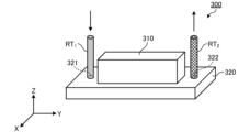
- FIG. 2 is a perspective view schematically showing the external configuration of the liquid droplet ejection head according to the embodiment.
- FIG. 3 is a plan view of the droplet ejection head according to the embodiment.
- FIG. 4 is a diagram schematically showing flow paths inside the droplet ejection head according to the embodiment.
- the droplet discharge head 300 has a housing including a box-shaped member 310 and a substantially flat plate-shaped member 320 .
- the housing of the droplet ejection head 300 has a supply port 321 for supplying the coloring liquid to the inside of the droplet ejection head 300 and a recovery port 322 for recovering the coloring liquid from the inside of the droplet ejection head 300 .
- the supply port 321 is connected to a first flow path RT1 for supplying the coloring liquid from the circulation mechanism 200 to the inside of the head.
- a second flow path RT 2 is connected to the recovery port 322 to return the coloring liquid recovered inside the head to the circulation mechanism 200 .
- the droplet ejection head 300 has a supply reservoir 301 , a supply manifold 302 , a recovery manifold 303 , a recovery reservoir 304 and an ejection unit 305 .
- the supply reservoir 301 has an elongated shape extending in the longitudinal direction (Y-axis direction) of the droplet discharge head 300 and is connected to the supply manifold 302 .
- the supply reservoir 301 has a channel inside. As shown in FIG. 4 , the coloring liquid supplied to the supply reservoir 301 through the first channel RT 1 and the supply port 321 and stored in the channel of the supply reservoir 301 is delivered to the supply manifold 302 .
- the supply manifold 302 has an elongated shape extending to the front of the recovery reservoir 304 in the lateral direction (X-axis direction) of the droplet ejection head 300 .
- the supply manifold 302 internally has a flow path that communicates with the flow path of the supply reservoir 301 and the discharge unit 305 . As shown in FIG. 4 , the coloring liquid delivered from the supply reservoir 301 to the supply manifold 302 is delivered from the supply manifold 302 to the ejection unit 305 .
- the recovery manifold 303 has an elongated shape extending in the lateral direction (X-axis direction) of the droplet ejection head 300 to the front of the supply reservoir 301 .
- the recovery manifold 303 internally has a channel that communicates with the channel of the recovery reservoir 304 and the discharge unit 305 . As shown in FIG. 4, the colored liquid that has not been discharged from the discharge unit 305 is sent to the collection manifold 303 .
- the recovery reservoir 304 has an elongated shape extending in the longitudinal direction (Y-axis direction) of the droplet discharge head 300 and is connected to the recovery manifold 303 .
- the recovery reservoir 304 has a channel inside. As shown in FIG. 4, the colored liquid sent from the recovery manifold 303 to the recovery reservoir 304 and stored in the flow path of the recovery reservoir 304 flows through the recovery port 322 and the second flow path RT2 into the tank 201 (see FIG. 6). ).
- FIG. 5 is a diagram schematically showing a configuration example of a discharge unit according to the embodiment.
- the discharge unit 305 has a nozzle 351 , a pressure chamber 352 and a displacement element 353 .
- the nozzle 351 is an ejection hole that opens to the ejection surface 30SF (see FIG. 1) of the droplet ejection head 300 .
- the pressurization chamber 352 is connected to the nozzle 351 .
- the pressure chamber 352 has a body portion 361 to which pressure is applied by the displacement element 353 and a descender 362 which is a flow path connecting the body portion 361 and the nozzle 351 .
- the pressurizing chamber 352 and the supply manifold 302 are connected via individual supply channels 354 .
- the colored liquid delivered from the supply manifold 302 to the discharge unit 305 is supplied to the pressurization chamber 352 through the individual supply channel 354 .
- the pressurization chamber 352 and the recovery manifold 303 are connected via individual recovery channels 355 .
- the colored liquid that has not been discharged from the nozzle 351 is recovered from the pressure chamber 352 to the recovery manifold 303 .
- the displacement element 353 is located on the side opposite to the descender 362 of the body portion 361 of the pressure chamber 352 .
- the displacement element 353 is an element that deforms according to a predetermined drive signal.
- the displacement element 353 functions as a pressurizing unit that applies pressure to the pressurizing chamber 352 to eject droplets of the colored liquid from the nozzle 351 . That is, by deforming the displacement element 353 , pressure (positive pressure and negative pressure) is applied to the pressure chamber 352 , and droplets of the colored liquid are discharged from the nozzle 351 .
- the displacement element 353 is electrically connected to the controller 2 and controlled by the controller 2 .
- the colored liquid is sucked from the supply manifold 302 by the negative pressure applied to the pressurizing chamber 352, and the sucked colored liquid is discharged from the nozzle 351 by the positive pressure applied to the pressurizing chamber 352. Discharge toward object 50 .
- FIG. 6 is a diagram schematically showing a circulation mechanism according to the embodiment.
- the circulation mechanism 200 includes a tank 201, a discharge pump 202, a suction pump 203, a first proportional valve 204, a second proportional valve 205, and a heater 206.
- the circulation mechanism 200 also includes a first pressure sensor 208 , a second pressure sensor 209 , a third pressure sensor 210 , a fourth pressure sensor 211 and a flow meter 212 .
- the circulation mechanism 200 also includes a first flow path RT- 1 and a second flow path RT -2 .
- the first flow path RT 1 is a flow path that communicates between the tank 201 and the droplet ejection head 300 and allows the colored liquid stored in the tank 201 to flow into the droplet ejection head 300 .
- the second flow path RT 2 is a flow path that communicates between the tank 201 and the droplet ejection head 300 and returns the colored liquid that has flowed into the droplet ejection head 300 back to the tank 201 .
- the colored liquid collected in the droplet ejection head 300 without being ejected from the droplet ejection head 300 to the outside is sent back to the tank 201 through the second flow path RT2 .
- the first flow path RT 1 and the second flow path RT 2 can be implemented, for example, by piping made of a predetermined material that does not interact with the components of the coloring liquid.
- the circulation mechanism 200 having such parts controls the circulation flow rate of the coloring liquid that circulates clockwise between the tank 201 and the droplet discharge head 300 as shown in FIG. .
- the tank 201 stores the coloring liquid supplied to the droplet ejection head 300 .
- the tank 201 functions as a storage section that stores the coloring liquid to be supplied to the droplet ejection head 300 .
- the ejection pump 202 supplies the colored liquid stored in the tank 201 to the droplet ejection head 300 through the first flow path RT1 .
- the ejection pump 202 generates positive pressure for sending the colored liquid stored in the tank 201 to the droplet ejection head 300 .
- the ejection pump 202 can, for example, deliver the colored liquid stored in the tank 201 to the droplet ejection head 300 at a preset constant supply pressure.
- the suction pump 203 feeds the colored liquid collected in the droplet discharge head 300 to the tank 201 through the second flow path RT2 .
- the suction pump 203 sucks the colored liquid collected in the droplet discharge head 300 and generates a negative pressure for sending it back to the tank 201 .
- the suction pump 203 can send the colored liquid sucked from the droplet ejection head 300 to the tank 201 at a preset constant recovery pressure, for example.
- the discharge pump 202 and the suction pump 203 can be implemented by rotary pumps such as gear pumps or positive displacement pumps such as diaphragm pumps.
- the first proportional valve 204 is interposed in the first flow path RT1 between the tank 201 and the droplet ejection head 300 and proportionally controls the flow rate of the coloring liquid supplied to the droplet ejection head 300 .
- the first proportional valve 204 can continuously change the flow cross-sectional area of the coloring liquid between 0% and 100%, and controls the flow rate of the coloring liquid to a desired flow rate.
- the first proportional valve 204 can reduce the supply flow rate when supplying the colored liquid to the droplet discharge head 300 by reducing the flow passage cross-sectional area of the colored liquid.
- the first proportional valve 204 can increase the supply flow rate when supplying the liquid to the droplet ejection head 300 by increasing the cross-sectional area of the liquid flow path.
- the second proportional valve 205 is interposed in the second flow path RT2 between the tank 201 and the droplet ejection head 300, and proportionally adjusts the flow rate of the coloring liquid supplied from the droplet ejection head 300 to the tank 201. Control. Like the first proportional valve 204, the second proportional valve 205 can continuously change the cross-sectional area of the liquid between 0% and 100%, and controls the flow rate of the coloring liquid to a desired flow rate. For example, the second proportional valve 205 can reduce the recovery flow rate when the colored liquid is recovered from the droplet ejection head 300 by reducing the cross-sectional area of the colored liquid flow path. On the other hand, the second proportional valve 205 can increase the recovery flow rate when the colored liquid is recovered from the droplet discharge head 300 by increasing the flow passage cross-sectional area of the colored liquid.
- the first proportional valve 204 and the second proportional valve 205 can be implemented by electromagnetic proportional switching valves or pneumatic proportional switching valves.
- the heater 206 is provided in the first flow path RT 1 or adjacent to the first flow path RT 1 and heats the coloring liquid flowing through the first flow path RT 1 .
- the first pressure sensor 208 measures the pressure of the colored liquid supplied from the tank 201 to the droplet ejection head 300 by the ejection pump 202 .
- the first pressure sensor 208 measures the pressure downstream of the discharge pump 202 in the circulation direction of the colored liquid in the circulation mechanism 200 .
- the first pressure sensor 208 sends the measurement result to the controller 21 .
- the second pressure sensor 209 measures the pressure of the colored liquid that is sucked from the droplet discharge head 300 by the suction pump 203 and fed to the tank 201 .
- the second pressure sensor 209 measures the pressure upstream of the suction pump 203 in the circulation direction of the coloring liquid in the circulation mechanism 200 .
- the second pressure sensor 209 sends the measurement result to the controller 21 .
- the third pressure sensor 210 functions as a first pressure measuring unit that measures the pressure of the colored liquid flowing between the first proportional valve 204 and the droplet ejection head 300 through the first flow path RT1 as the supply pressure. do.
- the third pressure sensor 210 sends the measurement result to the controller 21 .
- the fourth pressure sensor 211 functions as a second pressure measuring unit that measures the pressure of the colored liquid flowing between the second proportional valve 205 and the droplet ejection head 300 through the second flow path RT2 as the recovery pressure. do.
- the fourth pressure sensor 211 sends the measurement result to the controller 21 .
- the flow meter 212 measures the flow rate of the colored liquid supplied to the droplet ejection head 300 .
- the flow meter 212 sends the measurement results to the control section 21 .
- control unit 21 Based on the measurement result of the first pressure sensor 208 and the measurement result of the third pressure sensor 210, the control unit 21 adjusts the positive pressure applied to the coloring liquid when the discharge pump 202 delivers the coloring liquid so as to keep it constant. do.
- the control unit 21 controls the pressure of the colored liquid obtained from the measurement result of the first pressure sensor 208 to be 1.2 to 3 times higher than the pressure of the colored liquid obtained from the measurement result of the third pressure sensor 210.
- the positive pressure of the discharge pump 202 is adjusted so as to maintain a moderately large pressure.
- the control unit 21 adjusts the negative pressure applied to the coloring liquid when the suction pump 203 sucks the coloring liquid so as to keep it constant. do.
- the controller 21 controls the pressure of the colored liquid obtained from the measurement result of the second pressure sensor 209 to be 1.2 to 3 times higher than the pressure of the colored liquid obtained from the measurement result of the fourth pressure sensor 211.
- the negative pressure of the suction pump 203 is adjusted so as to maintain a moderately low pressure.
- the control unit 21 adjusts the pressure difference between the positive pressure applied to the colored liquid by the discharge pump 202 and the negative pressure applied to the colored liquid by the suction pump 203 so as to maintain a constant pressure difference between the tank 201 and the liquid.
- the colored liquid is circulated between the droplet ejection heads 300 .
- FIG. 7 is a flowchart showing the procedure of processing executed by the droplet ejection device according to the embodiment. Note that each process shown in FIG. 7 is executed under the control of the control unit 21 .
- step S101 an ejection process of ejecting droplets of a colored liquid from the droplet ejection head 300 is performed (step S101).
- the control unit 21 applies pressure to the pressure chamber 352 by controlling the displacement element 353 provided in the droplet ejection head 300 to eject the colored liquid from the nozzle 351 toward the object 50 .
- the cumulative processing period during which the ejection process is performed is referred to as an "ejection period.”
- control unit 21 controls the ejection pump 202 and the suction pump 203 to start circulation of the colored liquid between the tank 201 and the droplet ejection head 300 before starting the ejection process.
- step S102 it is determined whether or not the maintenance period for performing maintenance processing of the droplet ejection head 300 has arrived. The determination in step S102 is made, for example, based on whether or not the ejection period has exceeded a predetermined period. If the maintenance period has not yet arrived (step S102; No), the process returns to step S101, and the ejection process is continued.
- step S103 maintenance processing for the droplet ejection head 300 is performed (step S103).
- the control unit 21 controls the circulation mechanism 200 to adjust the circulation flow rate of the coloring liquid circulating between the circulation mechanism 200 and the droplet ejection head 300 .
- a mode of adjusting the circulation flow rate of the coloring liquid circulating between the circulation mechanism 200 and the droplet ejection head 300 will be described later.
- the control unit 21 ends a series of processes in the droplet ejection device 1 .
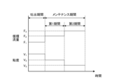
- FIG. 8 is an explanatory diagram for explaining an adjustment mode of the circulation flow rate according to the embodiment.
- FIG. 8 shows temporal changes in the "circulation flow rate” and "viscosity” during the discharge period and the maintenance period.
- “Circulation flow rate” refers to the circulation flow rate of the coloring liquid circulating between the circulation mechanism 200 and the droplet ejection head 300
- “viscosity” refers to the viscosity of the coloring liquid supplied from the circulation mechanism 200 to the droplet ejection head 300 . refers to viscosity.
- the control unit 21 controls the circulation mechanism 200 during the maintenance period after the ejection period to increase the circulation flow rate of the coloring liquid more than the circulation flow rate of the coloring liquid during the ejection period.
- the colored liquid is a pseudoplastic fluid whose viscosity decreases as the shear rate increases. The viscosity of the coloring liquid is reduced. Therefore, by increasing the circulation flow rate of the colored liquid during the maintenance period, the control section 21 can supply the droplet discharge head 300 with a colored liquid having a lower viscosity than the colored liquid during the discharge period.
- control unit 21 changes the flow passage cross-sectional area of the first proportional valve 204 and the second proportional valve 205 in the circulation mechanism 200 to change the supply flow rate and recovery flow rate of the coloring liquid, thereby changing the circulation flow rate during the discharge period. is increased from the circulation flow rate F 1 of the coloring liquid to a circulation flow rate F 2 (>F 1 ).
- the control unit 21 can reduce the viscosity of the colored liquid supplied to the droplet ejection head 300 during the maintenance period from the viscosity V 1 of the colored liquid during the ejection period to the viscosity V 2 ( ⁇ V 1 ). .
- the circulating flow rate of the colored liquid is increased more than the circulated flow rate of the colored liquid during the ejection period, thereby lowering the viscosity of the colored liquid compared to the viscosity of the colored liquid during the ejection period.
- the droplets can be ejected by reducing the viscosity of the colored liquid. It is possible to make it easier to peel off the accumulated matter from the inner wall of the flow path in the head 300 . As a result, the accumulated matter is smoothly discharged to the outside of the droplet discharge head 300 , so that it is possible to prevent the accumulated matter from obstructing the flow of the coloring liquid in the flow path inside the droplet discharge head 300 . As a result, it is possible to suppress ejection defects caused by residual matter remaining in the droplet ejection head 300 .
- the circulating flow rate of the colored liquid is increased during the entire maintenance period more than the circulating flow rate of the colored liquid during the discharge period.
- the circulation flow rate of the coloring liquid may be increased.
- the control unit 21 may control the circulation mechanism 200 during at least part of the maintenance period to increase the circulation flow rate of the coloring liquid more than that during the ejection period.
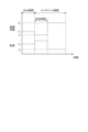
- FIG. 9 is an explanatory diagram for explaining the adjustment mode of the circulation flow rate according to Modification 1 of the embodiment.
- control unit 21 controls the circulation mechanism 200 to change the circulation flow rate of the coloring liquid between a first period and a second period following the first period included in the maintenance period. . Thereby, the control unit 21 can change the viscosity of the coloring liquid between the first period and the second period following the first period included in the maintenance period.
- control unit 21 changes the flow passage cross-sectional area of the first proportional valve 204 and the second proportional valve 205 in the circulation mechanism 200 to change the supply flow rate and recovery flow rate of the coloring liquid, thereby reducing the circulation flow rate to the first During the period, the circulation flow rate is set to F 2 , and during the second period, the circulation flow rate is set to F 3 ( ⁇ F 2 ). As a result, the control unit 21 can set the viscosity of the colored liquid supplied to the droplet ejection head 300 to V 2 during the first period and to V 3 (>V 2 ) during the second period. can.
- Modification 1 by changing the circulation flow rate of the colored liquid, it is possible to supply the liquid droplet discharge head 300 with a relatively low-viscosity colored liquid and a relatively high-viscosity colored liquid.
- the relatively low-viscosity colored liquid peels off the remaining matter from the inner wall of the flow path in the droplet discharge head 300, and the relatively high-viscosity colored liquid removes the remaining matter from the inside of the droplet discharge head 300. can be washed away.
- the circulation flow rate of the coloring liquid is changed from a relatively high flow rate (eg, circulation flow rate F 2 ) to a relatively low flow rate (eg, circulation flow rate F 3 ).
- the relatively high-viscosity colored liquid can be supplied to the droplet-discharging head 300 after the relatively low-viscosity colored liquid is supplied to the droplet-discharging head 300 . That is, after the staying matter is peeled off from the inner wall of the flow path in the droplet discharge head 300 by the relatively low-viscosity colored liquid, it remains in the droplet-discharge head 300 by the relatively high-viscosity colored liquid. Remaining matter can be washed away. As a result, according to Modification 1, the remaining matter can be more smoothly discharged to the outside of the droplet discharge head 300 .
- FIG. 10 is an explanatory diagram for explaining the adjustment mode of the circulation flow rate according to Modification 2 of the embodiment.
- the circulation flow rate of the coloring liquid is changed from a relatively high flow rate to a relatively low flow rate. Change to a higher flow rate.
- control unit 21 controls the circulation mechanism 200 to set the circulation flow rate to F2 in the first period and to F3 (> F2 ) in the second period. do.
- control unit 21 can set the viscosity of the colored liquid supplied to the droplet ejection head 300 to V 2 during the first period and to V 3 ( ⁇ V 2 ) during the second period. can.
- the circulation flow rate of the coloring liquid is changed from a relatively low flow rate (for example, circulation flow rate F 2 ) to a relatively high flow rate (for example, circulation flow rate F 3 ).
- the relatively low-viscosity colored liquid can be supplied to the droplet ejection head 300 after the relatively high-viscosity colored liquid is supplied to the droplet ejection head 300 . That is, after the staying matter remaining in the droplet ejection head 300 is washed away by the relatively high-viscosity coloring liquid, the remaining matter is removed from the flow path inside the droplet ejection head 300 by the relatively low-viscosity coloring liquid. It can be transported downstream at high speed. As a result, according to Modification 1, the remaining matter can be more smoothly discharged to the outside of the droplet discharge head 300 .
- control unit 21 may control the circulation mechanism 200 to repeat the process of changing the circulation flow rate of the coloring liquid a plurality of times during the maintenance period.
- FIG. 11 is an explanatory diagram for explaining the adjustment mode of the circulation flow rate according to Modification 3 of the embodiment.
- a solidified substance of the coloring liquid (hereinafter referred to as a “solidified substance” as appropriate) stays as a stagnant substance.
- the colored liquid contains a dissolving component capable of dissolving the solidified substance of the colored liquid, and the solidified substance remaining in the droplet ejection head 300 is dissolved by the dissolving component.
- control unit 21 controls the circulation mechanism 200 during the maintenance period to circulate the coloring liquid for a predetermined time period for the solidified matter remaining in the droplet discharge head 300 to dissolve in the dissolved component. is stopped, the circulation flow rate of the coloring liquid is increased.
- control unit 21 changes the cross-sectional area of the first proportional valve 204 and the second proportional valve 205 in the circulation mechanism 200 to 0 to stop the circulation of the coloring liquid for a predetermined period of time, thereby reducing the circulation flow rate to 0. and After a predetermined period of time, the control unit 21 increases the cross-sectional area of the flow passages of the first proportional valve 204 and the second proportional valve 205 in the circulation mechanism 200 to be greater than 0, thereby reducing the circulation flow rate to the level of the circulation of the colored liquid during the ejection period. Increase the circulation flow rate F2 , which is higher than the flow rate F1 .
- control unit 21 can reduce the viscosity of the colored liquid supplied to the droplet ejection head 300 to the viscosity V2 , which is lower than the viscosity V1 of the colored liquid during the ejection period, after the predetermined time has elapsed.
- the circulation of the coloring liquid is stopped for a predetermined time before increasing the circulation flow rate of the coloring liquid.
- the solidified matter remaining in the droplet ejection head 300 is dissolved in the dissolved component contained in the coloring liquid, and the solidified matter after dissolution is dissolved in the flow path in the droplet ejection head 300 by the coloring liquid. It can be transported downstream at high speed. As a result, according to Modification 3, the solidified colored liquid can be more smoothly discharged to the outside of the droplet discharge head 300 .
- FIG. 12 is an explanatory diagram for explaining the adjustment mode of the circulation flow rate according to Modification 4 of the embodiment.
- FIG. 12 shows temporal changes in the "head posture" during the ejection period and the maintenance period.
- “Head attitude” refers to the attitude of the droplet ejection head 300 mounted on the robot arm 100 .
- control unit 21 controls the circulation mechanism 200 to increase the circulation flow rate of the coloring liquid, and controls the robot arm 100 to eject droplets.
- the posture of the head 300 is changed.
- control unit 21 changes the flow passage cross-sectional area of the first proportional valve 204 and the second proportional valve 205 in the circulation mechanism 200 to change the supply flow rate and recovery flow rate of the coloring liquid, thereby changing the circulation flow rate during the discharge period. is increased from the circulation flow rate F 1 of the coloring liquid to a circulation flow rate F 2 (>F 1 ).
- the control unit 21 can reduce the viscosity of the colored liquid supplied to the droplet ejection head 300 during the maintenance period from the viscosity V 1 of the colored liquid during the ejection period to the viscosity V 2 ( ⁇ V 1 ). .
- control unit 21 maintains the posture of the droplet ejection head 300 at a constant posture P1 during the ejection period, and operates the arm unit 110 of the robot arm 100 during the maintenance period to eject droplets.
- the posture of the head 300 is sequentially changed to a plurality of arbitrary postures.
- the inclination of the droplet ejection head 300 with respect to the direction of gravity can be changed by changing the attitude of the droplet ejection head 300 during the maintenance period after the ejection period.
- the solidified colored liquid remaining in the droplet discharge head 300 tends to move in the direction of gravity under the force of gravity. Bubbles staying in the droplet discharge head 300 tend to move in the direction opposite to the direction of gravity due to buoyancy. Therefore, in Modified Example 4, by changing the attitude of the droplet discharge head 300, solidified substances of the colored liquid, bubbles, and the like staying in the droplet discharge head 300 are moved in the direction of gravity and in the direction of gravity. It can be effectively moved in the opposite direction. As a result, in Modification 4, the movement of the accumulated matter in the direction of gravity and in the direction opposite to the direction of gravity can be promoted, so that the accumulated matter can be smoothly discharged to the outside of the droplet discharge head 300 . can be done.
- the attitude of the droplet ejection head 300 is changed at the timing of increasing the circulation flow rate of the coloring liquid.
- the timing for starting the attitude change of the droplet ejection head 300 is matched with the timing for increasing the circulation flow rate of the coloring liquid.
- the posture of the droplet ejection head 300 is changed during the entire maintenance period. You can change your posture.
- the control unit 21 controls the circulation mechanism 200 to increase the circulation flow rate of the coloring liquid, and controls the robot arm 100 to increase the liquid droplet discharge head 300. You can change your posture.
- FIG. 13 is an explanatory diagram for explaining the adjustment mode of the circulation flow rate according to Modification 5 of the embodiment.
- FIG. 14 is a diagram schematically showing an example of the posture of the droplet ejection head according to Modification 5 of the embodiment. Modification 5 relates to a variation in attitude change of the droplet discharge head 300 in Modification 4. FIG.
- control unit 21 controls the robot arm 100 during the maintenance period after the ejection period so that the posture of the droplet ejection head 300 is adjusted so that the recovery port 322 is closer to the supply port 321 than the recovery port 321 is. Change to posture P2 , which is higher.
- the posture of the droplet ejection head 300 is changed to a posture in which the recovery port 322 is higher than the supply port 321.
- the height position may be reversed. That is, the controller 21 may change the posture of the droplet discharge head 300 to a posture in which the supply port 321 is higher than the recovery port 322 .
- the solidified colored liquid remaining in the droplet discharge head 300 can be efficiently moved in the direction of gravity.
- the movement of the solidified colored liquid in the direction from the supply port 321 to the recovery port 322 can be promoted, so that the solidified colored liquid can be smoothly discharged from the recovery port 322 to the outside of the droplet ejection head 300 . can do.
- FIG. 15 is an explanatory diagram for explaining the adjustment mode of the circulation flow rate according to Modification 6 of the embodiment.
- Modification 6 relates to a variation of the attitude change of the droplet ejection head 300 in Modification 5.
- FIG. 15 is an explanatory diagram for explaining the adjustment mode of the circulation flow rate according to Modification 6 of the embodiment.
- Modification 6 relates to a variation of the attitude change of the droplet ejection head 300 in Modification 5.
- FIG. 15 is an explanatory diagram for explaining the adjustment mode of the circulation flow rate according to Modification 6 of the embodiment.
- Modification 6 relates to a variation of the attitude change of the droplet ejection head 300 in Modification 5.
- FIG. 15 is an explanatory diagram for explaining the adjustment mode of the circulation flow rate according to Modification 6 of the embodiment.
- Modification 6 relates to a variation of the attitude change of the droplet ejection head 300 in Modification 5.
- FIG. 15 is an explanatory diagram for explaining the adjustment mode of the circulation flow rate according to Mod
- the control unit 21 sets the attitude of the droplet ejection head 300 to P2, in which the recovery port 322 is higher than the supply port 321, and to P2 , in which the supply port 321 is recovered.
- the posture is changed between posture P3 where the mouth 322 is higher.
- FIG. 16 is an explanatory diagram for explaining the adjustment mode of the circulation flow rate according to Modification 7 of the embodiment.
- FIG. 16 shows temporal changes in the "applied pressure” during the ejection period and the maintenance period.
- “Applied pressure” refers to the pressure applied from the displacement element 353 to the pressure chamber 352 in the droplet ejection head 300 .
- control unit 21 controls the circulation mechanism 200 during the maintenance period after the discharge period to increase the circulation flow rate of the coloring liquid and apply pressure to the pressure chamber 352 by the displacement element 353 .
- control unit 21 applies pressure C1 to the pressurizing chamber 352 by the displacement element 353 during the ejection period, and increases the circulation flow rate to F2 (> F1 ) during the maintenance period. maintains the application of pressure from to the pressurizing chamber 352 .
- control unit 21 can reduce the viscosity of the colored liquid supplied to the droplet ejection head 300 during the maintenance period from the viscosity V 1 of the colored liquid during the ejection period to the viscosity V 2 ( ⁇ V 1 ). .
- the viscosity of the colored liquid supplied to the droplet ejection head 300 is reduced by applying pressure to the pressurizing chamber 352 while increasing the circulation flow rate of the colored liquid.
- pressure waves can be generated in the pressurizing chamber 352 .
- the viscosity of the coloring liquid flowing through the pressure chamber 352 and the supply manifold 302 and recovery manifold 303 (hereinafter collectively referred to as "manifolds") connected to the pressure chamber 352 are reduced. ) can be made smaller.
- the pressure wave PW generated in the pressure chamber 352 is generated in the pressure chamber 352 as shown in FIG. Not only that, but it also becomes easier to propagate to the manifold.
- FIG. 17 is a diagram showing how pressure waves propagate according to Modification 7 of the embodiment. In this way, the pressure wave PW generated in the pressurizing chamber 352 propagates to the manifold, so that the accumulated matter remaining in the manifold can be intensively removed by the pressure wave PW.
- both the pressure applied to the pressurizing chamber 352 during the discharge period and the pressure applied to the pressurizing chamber 352 during the maintenance period are pressure C1 .
- the pressure applied to the pressurizing chamber 352 during the maintenance period may be lower than the pressure applied to the pressurizing chamber 352 during the ejection period (that is, the pressure for ejecting the colored liquid from the nozzle 351). .
- the flow path resistance of the individual recovery channel 355 connecting the pressure chamber 352 of the ejection unit 305 and the recovery manifold 303 causes the pressure chamber 352 and the supply manifold 302 to be separated. It is smaller than the channel resistance of the connecting individual supply channel 354 .
- the channel resistance of the individual recovery channel 355 is made smaller than the channel resistance of the individual supply channel 354. can do.
- the control unit 21 controls the circulation mechanism 200 to circulate the coloring liquid from the recovery port 322 toward the supply port 321 during the maintenance period after the ejection period. For example, during a first period included in the maintenance period, the controller 21 controls the circulation mechanism 200 to circulate the coloring liquid from the supply port 321 toward the recovery port 322 as shown in FIG. Then, in a second period following the first period included in the maintenance period, the control unit 21 controls the circulation mechanism 200 to reverse the flow direction of the coloring liquid, as shown in FIG. The coloring liquid is circulated from the port 322 toward the supply port 321 .
- the direction of circulation (flow direction) of the coloring liquid is changed from the direction from the supply port 321 to the recovery port 322 to the direction from the recovery port 322 to the supply port 321 .
- the colored liquid flows through the recovery reservoir 304, recovery manifold 303, individual recovery channel 355, discharge unit 305, individual supply channel 354, supply manifold 302, and supply reservoir 301 in this order.
- the channel resistance of the individual recovery channel 355 is smaller than the channel resistance of the individual supply channel 354 .
- the shear rate of the colored liquid increases in the individual recovery channel 355 , the viscosity of the colored liquid decreases, and the colored liquid with reduced viscosity flows through the discharge unit 305 and the individual supply channel 354 to the supply manifold 302 . It flows in and reaches the tip portion 302 a of the supply manifold 302 .
- the relatively high-viscosity colored liquid staying in the tip portion 302a of the supply manifold 302 can be replaced with the relatively low-viscosity colored liquid.
- the circulation mechanism 200 supplies the colored liquid to the droplet ejection head 300
- the supply section that supplies the colored liquid to the droplet ejection head 300 is not limited to the circulation mechanism 200
- the supply unit includes a plurality of liquid supply sources that respectively supply a plurality of colored liquids with different viscosities, a supply channel that connects the plurality of liquid supply sources and the droplet ejection head 300, and a supply channel for each liquid supply source. It may be a liquid supply mechanism including an on-off valve provided in the passage.
- the control unit 21 controls the opening/closing valve of the liquid supply mechanism during at least a part of the maintenance period after the ejection period, so that the color liquid is more than the colored liquid during the ejection period.
- a colored liquid having a low viscosity may be supplied to the droplet ejection head 300 .
- the colored liquid need not be a pseudoplastic fluid.
- the droplet discharge head 300 should at least have a nozzle 351, a pressure chamber 352 connected to the nozzle 351, and an actuator (displacement element 353) that applies pressure to the pressure chamber 352. good.
- the droplet ejection device (eg, droplet ejection device 1) according to the embodiment includes a droplet ejection head (eg, droplet ejection head 300) and a supply unit (eg, circulation mechanism 200). , and a control unit (for example, control unit 21).
- the droplet ejection head ejects droplets of the coloring liquid.
- the supply unit supplies the coloring liquid to the droplet ejection head.
- the control section controls each section.
- the control unit controls the supply unit during at least a part of the maintenance period after the ejection period for ejecting droplets of the colored liquid from the droplet ejection head so that the viscosity of the colored liquid is higher than that during the ejection period.
- a colored liquid having a low viscosity is supplied to the droplet ejection head.
- the colored liquid may be a pseudoplastic fluid whose viscosity decreases as the shear rate increases.
- the supply unit may be a circulation mechanism (for example, the circulation mechanism 200) that supplies the coloring liquid to the droplet ejection head while controlling the circulation flow rate of the coloring liquid that circulates between the droplet ejection head. Further, the control unit may control the circulation mechanism during at least a part of the maintenance period to increase the circulation flow rate of the coloring liquid more than the circulation flow rate of the coloring liquid during the ejection period.
- the circulating flow rate of the colored liquid is increased more than the circulated flow rate of the colored liquid during the ejection period, thereby lowering the viscosity of the colored liquid compared to the viscosity of the colored liquid during the ejection period.
- the control unit may control the circulation mechanism to change the circulation flow rate of the coloring liquid between a first period and a second period following the first period included in the maintenance period.
- the control unit may control the circulation mechanism to change the circulation flow rate of the coloring liquid between a first period and a second period following the first period included in the maintenance period.
- the control unit may control the circulation mechanism to set the circulation flow rate of the coloring liquid to a first flow rate during the first period and to a second flow rate that is lower than the first flow rate during the second period.
- the control unit may control the circulation mechanism to set the circulation flow rate of the coloring liquid to a first flow rate during the first period and to a second flow rate higher than the first flow rate during the second period.
- the control unit may control the circulation mechanism to stop the circulation of the coloring liquid for a predetermined time, and then increase the circulation flow rate of the coloring liquid.
- the control unit may control the circulation mechanism to stop the circulation of the coloring liquid for a predetermined time, and then increase the circulation flow rate of the coloring liquid.
- the droplet ejection device may further include a robot arm (for example, robot arm 100).
- the robot arm mounts the liquid droplet ejection head so that its posture can be changed.
- the control unit controls the circulation mechanism to increase the circulation flow rate of the coloring liquid, and controls the robot arm to change the attitude of the droplet discharge head.
- the controller may change the attitude of the droplet discharge head at the timing of increasing the circulation flow rate of the coloring liquid.
- the droplet ejection head has a supply port (for example, supply port 321) for supplying colored liquid to the inside of the droplet ejection head and a recovery port (for example, collection port 322). Further, the control unit may change the attitude of the droplet ejection head so that one of the supply port and the recovery port is higher than the other. As a result, according to the droplet ejection device according to the embodiment, solidified matter or air bubbles of the colored liquid can be smoothly discharged from the recovery port to the outside of the droplet ejection head.
- the controller changes the posture of the droplet ejection head between a posture in which one of the supply port and the recovery port is higher than the other and a posture in which the other of the supply port and the recovery port is higher than the other. good too.
- the droplet ejection head may have an ejection unit (eg, ejection unit 305), a supply manifold (eg, supply manifold 302), and a recovery manifold (eg, recovery manifold 303).
- the discharge unit may include a nozzle (eg, nozzle 351), a pressure chamber (eg, pressure chamber 352), and a pressure member (eg, displacement element 353).
- a pressurized chamber is connected to the nozzle.
- the pressurizing section applies pressure to the pressurizing chamber to eject droplets of the colored liquid from the nozzle.
- the supply manifold is connected to the pressurization chamber and supplies the coloring liquid to the pressurization chamber.
- the recovery manifold is connected to the pressurization chamber and recovers the coloring liquid from the pressurization chamber.
- the control unit may control the circulation mechanism to increase the circulation flow rate of the coloring liquid during at least part of the maintenance period, and apply pressure to the pressurization chamber by the pressurization unit.
- the droplet ejection head may have an ejection unit (eg, ejection unit 305), a supply manifold (eg, supply manifold 302), and a recovery manifold (eg, recovery manifold 303).
- the discharge unit may include a nozzle (eg, nozzle 351), a pressure chamber (eg, pressure chamber 352), and a pressure member (eg, displacement element 353).
- a pressurized chamber is connected to the nozzle.
- the pressurizing section applies pressure to the pressurizing chamber to eject droplets of the colored liquid from the nozzle.
- the supply manifold is connected to the pressurizing chamber, and supplies the coloring liquid supplied from the supply port (for example, the supply port 321) side of the droplet ejection head to the pressurizing chamber.
- the recovery manifold is connected to the pressurization chamber, recovers the colored liquid from the pressurization chamber, and delivers it to the recovery port (for example, the recovery port 322) side of the droplet ejection head.
- the pressure chamber and the supply manifold may be connected via individual supply channels (for example, individual supply channels 354).
- the pressurized chamber and the recovery manifold may be connected via an individual recovery channel (for example, individual recovery channel 355).
- the channel resistance of the individual recovery channel may be smaller than the channel resistance of the individual supply channel.
- control unit may control the circulation mechanism during at least part of the maintenance period to circulate the coloring liquid from the recovery port toward the supply port.
Landscapes
- Ink Jet (AREA)
Abstract
This droplet discharging device comprises: a droplet discharging head; a supply unit; and a control unit. The droplet discharging head discharges droplets of a colored liquid. The supply unit supplies the colored liquid to the droplet discharging head. The control unit controls the aforementioned units. Moreover, during at least a part of a maintenance period after a discharging period during which the droplets of the colored liquid are discharged from the droplet discharging head, the control unit controls the supply unit to supply to the droplet discharging head a colored liquid having lower viscosity than the colored liquid discharged during the discharging period.
Description
開示の実施形態は、液滴吐出装置及びメンテナンス方法に関する。
The disclosed embodiments relate to a droplet ejection device and a maintenance method.
印刷装置として、インクジェット記録方式を利用したインクジェットプリンタやインクジェットプロッタが知られている。このようなインクジェット方式の印刷装置には、液体を吐出させるための液滴吐出ヘッドが搭載されている。
Inkjet printers and inkjet plotters that use the inkjet recording method are known as printing devices. Such an inkjet printing apparatus is equipped with a droplet ejection head for ejecting liquid.
また、インクジェット方式の印刷装置では、液滴吐出ヘッドに洗浄液を供給して液滴吐出ヘッドの目詰まりを抑止する技術が提案されている。
In addition, for inkjet printing apparatuses, a technique has been proposed for suppressing clogging of the droplet ejection head by supplying a cleaning liquid to the droplet ejection head.
実施形態の一態様による液滴吐出装置は、液滴吐出ヘッドと、供給部と、制御部とを備える。液滴吐出ヘッドは、着色液の液滴を吐出する。供給部は、液滴吐出ヘッドに着色液を供給する。制御部は、各部を制御する。また、制御部は、液滴吐出ヘッドから着色液の液滴を吐出する吐出期間の後のメンテナンス期間のうち少なくとも一部の期間に、供給部を制御して、吐出期間における着色液よりも粘度が低い着色液を液滴吐出ヘッドに供給する。
A droplet ejection device according to one aspect of an embodiment includes a droplet ejection head, a supply section, and a control section. The droplet ejection head ejects droplets of the coloring liquid. The supply unit supplies the coloring liquid to the droplet ejection head. The control section controls each section. In addition, the control unit controls the supply unit during at least a part of the maintenance period after the ejection period for ejecting droplets of the colored liquid from the droplet ejection head so that the viscosity of the colored liquid is higher than that during the ejection period. A colored liquid having a low viscosity is supplied to the droplet ejection head.
以下、添付図面を参照して、本願の開示する液滴吐出装置及びメンテナンス方法の実施形態について説明する。なお、以下に示す実施形態により本開示が限定されるものではない。また、図面は模式的なものであり、各要素の寸法の関係、各要素の比率などは、現実と異なる場合があることに留意する必要がある。さらに、図面の相互間においても、互いの寸法の関係や比率が異なる部分が含まれている場合がある。
Embodiments of the droplet discharge device and the maintenance method disclosed in the present application will be described below with reference to the accompanying drawings. It should be noted that the present disclosure is not limited by the embodiments shown below. Also, it should be noted that the drawings are schematic, and the relationship of dimensions of each element, the ratio of each element, and the like may differ from reality. Furthermore, even between the drawings, there are cases where portions having different dimensional relationships and ratios are included.
また、以下に示す実施形態では、「一定」、「直交」、「垂直」あるいは「平行」といった表現が用いられる場合があるが、これらの表現は、厳密に「一定」、「直交」、「垂直」あるいは「平行」であることを要しない。すなわち、上記した各表現は、たとえば製造精度、設置精度などのずれを許容するものとする。
Further, in the embodiments described below, expressions such as "constant", "perpendicular", "perpendicular" or "parallel" may be used, but these expressions are strictly "constant", "perpendicular", " It does not have to be "perpendicular" or "parallel". That is, each of the expressions described above allows deviations in, for example, manufacturing accuracy and installation accuracy.
また、各実施形態は、処理内容を矛盾させない範囲で適宜組み合わせることが可能である。また、以下の各実施形態において同一の部位には同一の符号を付し、重複する説明は省略される。
In addition, each embodiment can be appropriately combined within a range that does not contradict the processing content. Also, in each of the following embodiments, the same parts are denoted by the same reference numerals, and overlapping descriptions are omitted.
本願が開示する液滴吐出装置は、インクジェット記録方式を利用したインクジェットプリンタやインクジェットプロッタの他、インクジェット方式で液滴を吐出する各種装置に適用できる。
The droplet ejection device disclosed in the present application can be applied to various devices that eject droplets by the inkjet method, in addition to inkjet printers and inkjet plotters that use the inkjet recording method.
<液滴吐出装置の外観構成例>
図1を用いて、実施形態に係る液滴吐出装置の構成について説明する。図1は、実施形態に係る液滴吐出装置の構成例を模式的に示す図である。 <External Configuration Example of Droplet Ejecting Device>
The configuration of the droplet ejection device according to the embodiment will be described with reference to FIG. FIG. 1 is a diagram schematically showing a configuration example of a droplet ejection device according to an embodiment.
図1に示すように、液滴吐出装置1は、ロボットアーム100と、循環機構200と、液滴吐出ヘッド300と、制御装置2とを備える。
As shown in FIG. 1, the droplet ejection device 1 includes a robot arm 100, a circulation mechanism 200, a droplet ejection head 300, and a control device 2.
ロボットアーム100は、例えば室内又は室外の水平な床面に載置される基台10に組み付けられる。ロボットアーム100は、アーム部110を有する。アーム部110は、曲げ伸ばし、及び回転自在に組み付けられた複数の部品により構成される。アーム部110は、後述する制御部21からの指令に従って、アーム部110の先端に搭載された液滴吐出ヘッド300の移動や、かかる液滴吐出ヘッド300の位置、姿勢、並びに角度の変更などを行うことができる。図1に例示するアーム部110は、液滴吐出ヘッド300にとって必要となる移動や、位置、姿勢、並びに角度などの変更が可能な自由度を備えていれば、図1に示す構成に特に限定されるものではない。
The robot arm 100 is assembled to a base 10 that is placed on a horizontal floor indoors or outdoors, for example. The robot arm 100 has an arm section 110 . The arm portion 110 is composed of a plurality of parts that are assembled so as to be bendable, stretchable, and rotatable. The arm unit 110 moves the droplet ejection head 300 mounted on the tip of the arm unit 110 and changes the position, posture, and angle of the droplet ejection head 300 in accordance with commands from the control unit 21, which will be described later. It can be carried out. The arm unit 110 illustrated in FIG. 1 is particularly limited to the configuration shown in FIG. not to be
ロボットアーム100は、アーム部110によって、例えば、アーム部110の先端に搭載された循環機構200及び液滴吐出ヘッド300を所定の回転軸に沿って移動させることにより、垂直方向(Z軸方向)に移動させることができる。これにより、循環機構200及び液滴吐出ヘッド300は、例えば、図1に示すように、対象物50の吹付面50SFに対して、液滴吐出ヘッド300の液体の吐出面30SFを平行に対面させた姿勢をとることができる。また、ロボットアーム100は、アーム部110によって、例えば、アーム部110の先端に組み付けられた循環機構200及び液滴吐出ヘッド300を所定の回転軸回りに回転させることができる。これにより、循環機構200及び液滴吐出ヘッド300は、例えば、長手方向の位置と短手方向の位置を入れ替えたり、上下の位置を反転させたりすることができる。
The robot arm 100 moves, for example, the circulation mechanism 200 and the droplet discharge head 300 mounted on the tip of the arm portion 110 along a predetermined rotation axis by the arm portion 110, thereby moving the robot arm 100 in the vertical direction (Z-axis direction). can be moved to As a result, the circulation mechanism 200 and the droplet ejection head 300, for example, as shown in FIG. can take a stance. Further, the robot arm 100 can rotate the circulation mechanism 200 and the liquid droplet ejection head 300 attached to the tip of the arm portion 110 around a predetermined rotation axis by the arm portion 110 . As a result, the circulation mechanism 200 and the liquid droplet ejection head 300 can, for example, exchange their longitudinal and lateral positions, or reverse their vertical positions.
循環機構200は、ロボットアーム100のアーム部110の先端部に設置される。循環機構200は、液滴吐出ヘッド300との間を循環する着色液の循環流量を制御しつつ、液滴吐出ヘッド300に着色液を供給する。循環機構200は、液滴吐出ヘッド300に着色液を供給する供給部として機能する。
The circulation mechanism 200 is installed at the tip of the arm section 110 of the robot arm 100 . The circulation mechanism 200 supplies the coloring liquid to the droplet ejection heads 300 while controlling the circulation flow rate of the coloring liquid circulating between the droplet ejection heads 300 . The circulation mechanism 200 functions as a supply section that supplies the coloring liquid to the droplet ejection head 300 .
液滴吐出ヘッド300は、ロボットアーム100のアーム部110の先端部に設置された循環機構200に組み付けられる。液滴吐出ヘッド300は、対象物50に対して、着色液の液滴を吐出する液滴吐出部として機能する。着色液は、対象物50に塗布して着色することが可能な液体である。また、着色液は、せん断速度が増加するほど粘度が低下する擬塑性流体である場合を例示して説明するが、擬塑性流体でなくても構わない。着色液としては、例えば、インクや塗料等を用いることができる。
The droplet ejection head 300 is attached to the circulation mechanism 200 installed at the tip of the arm portion 110 of the robot arm 100 . The droplet ejection head 300 functions as a droplet ejection section that ejects droplets of the coloring liquid onto the object 50 . The coloring liquid is a liquid that can be applied to the object 50 to color it. Also, the colored liquid is described by exemplifying a case where the viscosity is reduced as the shear rate increases, but the colored liquid may not be a pseudo-plastic fluid. As the coloring liquid, for example, ink or paint can be used.
制御装置2は、たとえばコンピュータであり、プロセッサ等の制御部21とメモリ等の記憶部22とを備える。記憶部22には、液滴吐出装置1において実行される各種の処理を制御するプログラムが格納される。制御部21は、記憶部22に記憶されたプログラムを読み出して実行することによって液滴吐出装置1の動作を制御する。
The control device 2 is, for example, a computer, and includes a control section 21 such as a processor and a storage section 22 such as a memory. The storage unit 22 stores programs for controlling various processes executed in the droplet ejection device 1 . The control unit 21 controls the operation of the droplet ejection device 1 by reading out and executing programs stored in the storage unit 22 .
なお、かかるプログラムは、コンピュータによって読み取り可能な記憶媒体に記録されていたものであって、その記憶媒体から制御装置2の記憶部22にインストールされたものであってもよい。コンピュータによって読み取り可能な記憶媒体としては、たとえばハードディスク(HD)、フレキシブルディスク(FD)、コンパクトディスク(CD)、マグネットオプティカルディスク(MO)、メモリカードなどがある。
The program may be recorded in a computer-readable storage medium and installed in the storage unit 22 of the control device 2 from the storage medium. Examples of computer-readable storage media include hard disks (HD), flexible disks (FD), compact disks (CD), magnet optical disks (MO), and memory cards.
ところで、着色液の液滴を吐出した後の液滴吐出ヘッド300内には、種々の滞留物が滞留することがある。滞留物としては、例えば、着色液の固化物や気泡等が挙げられる。液滴吐出ヘッド300内に滞留物が滞留すると、着色液の流れが妨げられるため、液滴吐出ヘッド300の吐出不良が発生するおそれがある。この点に鑑み、本願は、液滴吐出ヘッド300内に残留する滞留物に起因した吐出不良を抑制することができる液滴吐出装置1を提案する。
By the way, in the droplet ejection head 300 after the droplets of the coloring liquid have been ejected, various staying matter may remain. Examples of the retained matter include solidified colored liquid and air bubbles. If the stagnant matter stays in the droplet discharge head 300, the flow of the colored liquid is obstructed, so there is a risk that the droplet discharge head 300 will cause a discharge failure. In view of this point, the present application proposes a droplet ejection device 1 capable of suppressing ejection defects caused by stagnant substances remaining in the droplet ejection head 300 .
<液滴吐出ヘッドの構成例>
図2~図4を用いて、実施形態に係る液滴吐出ヘッド300について説明する。図2は、実施形態に係る液滴吐出ヘッドの外観構成を模式的に示す斜視図である。図3は、実施形態に係る液滴吐出ヘッドの平面図である。図4は、実施形態に係る液滴吐出ヘッドの内部の流路を模式的に示す図である。 <Configuration Example of Droplet Discharge Head>
Adroplet discharge head 300 according to an embodiment will be described with reference to FIGS. 2 to 4. FIG. FIG. 2 is a perspective view schematically showing the external configuration of the liquid droplet ejection head according to the embodiment. FIG. 3 is a plan view of the droplet ejection head according to the embodiment. FIG. 4 is a diagram schematically showing flow paths inside the droplet ejection head according to the embodiment.
図2~図4を用いて、実施形態に係る液滴吐出ヘッド300について説明する。図2は、実施形態に係る液滴吐出ヘッドの外観構成を模式的に示す斜視図である。図3は、実施形態に係る液滴吐出ヘッドの平面図である。図4は、実施形態に係る液滴吐出ヘッドの内部の流路を模式的に示す図である。 <Configuration Example of Droplet Discharge Head>
A
図2に示すように、液滴吐出ヘッド300は、箱型の部材310と略平板形状の部材320とを含む筐体を備えている。液滴吐出ヘッド300の筐体には、液滴吐出ヘッド300の内部に着色液を供給するための供給口321と、液滴吐出ヘッド300の内部から着色液を回収するための回収口322とが設けられている。供給口321には、循環機構200からヘッド内部に着色液を供給するための第1の流路RT1が、接続されている。回収口322には、ヘッド内部で回収された着色液を循環機構200に送り出す返すための第2の流路RT2が接続されている。
As shown in FIG. 2, the droplet discharge head 300 has a housing including a box-shaped member 310 and a substantially flat plate-shaped member 320 . The housing of the droplet ejection head 300 has a supply port 321 for supplying the coloring liquid to the inside of the droplet ejection head 300 and a recovery port 322 for recovering the coloring liquid from the inside of the droplet ejection head 300 . is provided. The supply port 321 is connected to a first flow path RT1 for supplying the coloring liquid from the circulation mechanism 200 to the inside of the head. A second flow path RT 2 is connected to the recovery port 322 to return the coloring liquid recovered inside the head to the circulation mechanism 200 .
図3に示すように、液滴吐出ヘッド300は、供給リザーバ301と、供給マニホールド302と、回収マニホールド303と、回収リザーバ304と、吐出ユニット305とを有している。
As shown in FIG. 3 , the droplet ejection head 300 has a supply reservoir 301 , a supply manifold 302 , a recovery manifold 303 , a recovery reservoir 304 and an ejection unit 305 .
供給リザーバ301は、液滴吐出ヘッド300の長手方向(Y軸方向)に伸びた細長い形状を有し、供給マニホールド302と繋がっている。供給リザーバ301は、内部に流路を有する。図4に示すように、第1の流路RT1及び供給口321通じて供給リザーバ301に供給され、供給リザーバ301の流路に貯留された着色液は、供給マニホールド302へと送り出される。
The supply reservoir 301 has an elongated shape extending in the longitudinal direction (Y-axis direction) of the droplet discharge head 300 and is connected to the supply manifold 302 . The supply reservoir 301 has a channel inside. As shown in FIG. 4 , the coloring liquid supplied to the supply reservoir 301 through the first channel RT 1 and the supply port 321 and stored in the channel of the supply reservoir 301 is delivered to the supply manifold 302 .
供給マニホールド302は、液滴吐出ヘッド300の短手方向(X軸方向)に回収リザーバ304の手前まで延伸した細長い形状を有する。供給マニホールド302は、供給リザーバ301が有する流路及び吐出ユニット305に連通した流路を内部に有する。図4に示すように、供給リザーバ301から供給マニホールド302へと送り出された着色液は、供給マニホールド302から吐出ユニット305へと送り出される。
The supply manifold 302 has an elongated shape extending to the front of the recovery reservoir 304 in the lateral direction (X-axis direction) of the droplet ejection head 300 . The supply manifold 302 internally has a flow path that communicates with the flow path of the supply reservoir 301 and the discharge unit 305 . As shown in FIG. 4 , the coloring liquid delivered from the supply reservoir 301 to the supply manifold 302 is delivered from the supply manifold 302 to the ejection unit 305 .
回収マニホールド303は、液滴吐出ヘッド300の短手方向(X軸方向)に供給リザーバ301の手前まで延伸した細長い形状を有する。回収マニホールド303は、回収リザーバ304が有する流路及び吐出ユニット305と連通した流路を内部に有する。図4に示すように、吐出ユニット305から外部へ吐出されなかった着色液は、回収マニホールド303へと送り出される。
The recovery manifold 303 has an elongated shape extending in the lateral direction (X-axis direction) of the droplet ejection head 300 to the front of the supply reservoir 301 . The recovery manifold 303 internally has a channel that communicates with the channel of the recovery reservoir 304 and the discharge unit 305 . As shown in FIG. 4, the colored liquid that has not been discharged from the discharge unit 305 is sent to the collection manifold 303 .
回収リザーバ304は、液滴吐出ヘッド300の長手方向(Y軸方向)に伸びた細長い形状を有し、回収マニホールド303と繋がっている。回収リザーバ304は、内部に流路を有する。図4に示すように、回収マニホールド303から回収リザーバ304に送り出され、回収リザーバ304の流路に貯留された着色液は、回収口322及び第2の流路RT2を通じて、タンク201(図6参照)へと送り返される。
The recovery reservoir 304 has an elongated shape extending in the longitudinal direction (Y-axis direction) of the droplet discharge head 300 and is connected to the recovery manifold 303 . The recovery reservoir 304 has a channel inside. As shown in FIG. 4, the colored liquid sent from the recovery manifold 303 to the recovery reservoir 304 and stored in the flow path of the recovery reservoir 304 flows through the recovery port 322 and the second flow path RT2 into the tank 201 (see FIG. 6). ).
図5は、実施形態に係る吐出ユニットの構成例を模式的に示す図である。図5に示すように、吐出ユニット305は、ノズル351と、加圧室352と、変位素子353とを有する。ノズル351は、液滴吐出ヘッド300の吐出面30SF(図1参照)に開口している吐出孔である。
FIG. 5 is a diagram schematically showing a configuration example of a discharge unit according to the embodiment. As shown in FIG. 5, the discharge unit 305 has a nozzle 351 , a pressure chamber 352 and a displacement element 353 . The nozzle 351 is an ejection hole that opens to the ejection surface 30SF (see FIG. 1) of the droplet ejection head 300 .
加圧室352は、ノズル351に繋がっている。加圧室352は、変位素子353によって圧力が付与される本体部361と、本体部361とノズル351とを繋ぐ流路であるディセンダ362とを有する。加圧室352と供給マニホールド302とは、個別供給流路354を介して繋がっている。供給マニホールド302から吐出ユニット305へと送り出された着色液は、個別供給流路354を通じて、加圧室352に供給される。また、加圧室352と回収マニホールド303とは、個別回収流路355を介して繋がっている。ノズル351から外部へ吐出されなかった着色液は、加圧室352から回収マニホールド303へと回収される。
The pressurization chamber 352 is connected to the nozzle 351 . The pressure chamber 352 has a body portion 361 to which pressure is applied by the displacement element 353 and a descender 362 which is a flow path connecting the body portion 361 and the nozzle 351 . The pressurizing chamber 352 and the supply manifold 302 are connected via individual supply channels 354 . The colored liquid delivered from the supply manifold 302 to the discharge unit 305 is supplied to the pressurization chamber 352 through the individual supply channel 354 . In addition, the pressurization chamber 352 and the recovery manifold 303 are connected via individual recovery channels 355 . The colored liquid that has not been discharged from the nozzle 351 is recovered from the pressure chamber 352 to the recovery manifold 303 .
変位素子353は、加圧室352の本体部361のディセンダ362とは反対側の面に位置している。変位素子353は、所定の駆動信号に応じて変形する素子である。変位素子353は、加圧室352にノズル351から着色液の液滴を吐出させるための圧力を加える加圧部として機能する。すなわち、変位素子353が変形することにより、加圧室352に圧力(正圧及び負圧)が加えられ、ノズル351から着色液の液滴が吐出される。変位素子353は、制御装置2に電気的に接続されており、制御装置2によって制御される。
The displacement element 353 is located on the side opposite to the descender 362 of the body portion 361 of the pressure chamber 352 . The displacement element 353 is an element that deforms according to a predetermined drive signal. The displacement element 353 functions as a pressurizing unit that applies pressure to the pressurizing chamber 352 to eject droplets of the colored liquid from the nozzle 351 . That is, by deforming the displacement element 353 , pressure (positive pressure and negative pressure) is applied to the pressure chamber 352 , and droplets of the colored liquid are discharged from the nozzle 351 . The displacement element 353 is electrically connected to the controller 2 and controlled by the controller 2 .
かかる構成を有する吐出ユニット305は、加圧室352に加えられた負圧によって供給マニホールド302から着色液を吸引し、吸引した着色液を加圧室352に加えられた正圧によってノズル351から対象物50に向かって吐出させる。
In the discharge unit 305 having such a configuration, the colored liquid is sucked from the supply manifold 302 by the negative pressure applied to the pressurizing chamber 352, and the sucked colored liquid is discharged from the nozzle 351 by the positive pressure applied to the pressurizing chamber 352. Discharge toward object 50 .
<循環機構の構成例>
続いて、実施形態に係る循環機構200の構成例を説明する。図6は、実施形態に係る循環機構を模式的に示す図である。 <Configuration example of circulation mechanism>
Next, a configuration example of thecirculation mechanism 200 according to the embodiment will be described. FIG. 6 is a diagram schematically showing a circulation mechanism according to the embodiment;
続いて、実施形態に係る循環機構200の構成例を説明する。図6は、実施形態に係る循環機構を模式的に示す図である。 <Configuration example of circulation mechanism>
Next, a configuration example of the
図6に示すように、循環機構200は、タンク201と、吐出ポンプ202と、吸引ポンプ203と、第1比例弁204と、第2比例弁205と、ヒーター206とを備える。また、循環機構200は、第1圧力センサ208と、第2圧力センサ209と、第3圧力センサ210と、第4圧力センサ211と、流量計212とを備える。
As shown in FIG. 6, the circulation mechanism 200 includes a tank 201, a discharge pump 202, a suction pump 203, a first proportional valve 204, a second proportional valve 205, and a heater 206. The circulation mechanism 200 also includes a first pressure sensor 208 , a second pressure sensor 209 , a third pressure sensor 210 , a fourth pressure sensor 211 and a flow meter 212 .
また、循環機構200は、第1の流路RT1と、第2の流路RT2とを備える。第1の流路RT1は、タンク201と液滴吐出ヘッド300との間を連通し、タンク201に貯留された着色液を液滴吐出ヘッド300の内部に流入させるための流路である。第2の流路RT2は、タンク201と液滴吐出ヘッド300との間を連通し、液滴吐出ヘッド300に流入した着色液をタンク201に還流させるための流路である。第2の流路RT2を通じて、液滴吐出ヘッド300から外部に吐出されずに、液滴吐出ヘッド300内で回収された着色液はタンク201に送り返される。第1の流路RT1及び第2の流路RT2は、例えば、着色液の成分との相互作用がない所定の材料で形成された配管により実装できる。かかる各部を有する循環機構200は、制御部21による制御に従って、例えば、図6に示すように、タンク201と液滴吐出ヘッド300との間を右回りに循環する着色液の循環流量を制御する。
The circulation mechanism 200 also includes a first flow path RT- 1 and a second flow path RT -2 . The first flow path RT 1 is a flow path that communicates between the tank 201 and the droplet ejection head 300 and allows the colored liquid stored in the tank 201 to flow into the droplet ejection head 300 . The second flow path RT 2 is a flow path that communicates between the tank 201 and the droplet ejection head 300 and returns the colored liquid that has flowed into the droplet ejection head 300 back to the tank 201 . The colored liquid collected in the droplet ejection head 300 without being ejected from the droplet ejection head 300 to the outside is sent back to the tank 201 through the second flow path RT2 . The first flow path RT 1 and the second flow path RT 2 can be implemented, for example, by piping made of a predetermined material that does not interact with the components of the coloring liquid. The circulation mechanism 200 having such parts controls the circulation flow rate of the coloring liquid that circulates clockwise between the tank 201 and the droplet discharge head 300 as shown in FIG. .
タンク201は、液滴吐出ヘッド300に供給される着色液を貯留する。タンク201は、液滴吐出ヘッド300に供給する着色液を貯留する貯留部として機能する。
The tank 201 stores the coloring liquid supplied to the droplet ejection head 300 . The tank 201 functions as a storage section that stores the coloring liquid to be supplied to the droplet ejection head 300 .
吐出ポンプ202は、第1の流路RT1を通じて、タンク201に貯留された着色液を液滴吐出ヘッド300に送給する。吐出ポンプ202は、タンク201に貯留された着色液を液滴吐出ヘッド300に送り出すための正圧を発生させる。吐出ポンプ202は、例えば、予め設定された一定の供給圧力で、タンク201に貯留された着色液を液滴吐出ヘッド300に送出できる。
The ejection pump 202 supplies the colored liquid stored in the tank 201 to the droplet ejection head 300 through the first flow path RT1 . The ejection pump 202 generates positive pressure for sending the colored liquid stored in the tank 201 to the droplet ejection head 300 . The ejection pump 202 can, for example, deliver the colored liquid stored in the tank 201 to the droplet ejection head 300 at a preset constant supply pressure.
吸引ポンプ203は、第2の流路RT2を通じて、液滴吐出ヘッド300において回収された着色液をタンク201に送給する。吸引ポンプ203は、液滴吐出ヘッド300において回収された着色液を吸引して、タンク201に送り返すための負圧を発生させる。吸引ポンプ203は、例えば、予め設定された一定の回収圧力で、液滴吐出ヘッド300から吸引した着色液をタンク201に送出できる。
The suction pump 203 feeds the colored liquid collected in the droplet discharge head 300 to the tank 201 through the second flow path RT2 . The suction pump 203 sucks the colored liquid collected in the droplet discharge head 300 and generates a negative pressure for sending it back to the tank 201 . The suction pump 203 can send the colored liquid sucked from the droplet ejection head 300 to the tank 201 at a preset constant recovery pressure, for example.
吐出ポンプ202及び吸引ポンプ203は、ギアポンプなどの回転ポンプや、ダイヤフラムポンプなど容積式ポンプにより実装できる。
The discharge pump 202 and the suction pump 203 can be implemented by rotary pumps such as gear pumps or positive displacement pumps such as diaphragm pumps.
第1比例弁204は、タンク201と液滴吐出ヘッド300との間の第1の流路RT1に介挿され、液滴吐出ヘッド300に供給する着色液の流量を比例制御する。第1比例弁204は、着色液の流路断面積を0~100%の間で連続的に変更可能であり、着色液の流量を所望の流量に制御する。例えば、第1比例弁204は、着色液の流路断面積を小さくすることにより、液滴吐出ヘッド300に着色液を供給する際の供給流量を小さくできる。一方、第1比例弁204は、液体の流路断面積を大きくすることにより、液滴吐出ヘッド300に液体を供給する際の供給流量を大きくできる。
The first proportional valve 204 is interposed in the first flow path RT1 between the tank 201 and the droplet ejection head 300 and proportionally controls the flow rate of the coloring liquid supplied to the droplet ejection head 300 . The first proportional valve 204 can continuously change the flow cross-sectional area of the coloring liquid between 0% and 100%, and controls the flow rate of the coloring liquid to a desired flow rate. For example, the first proportional valve 204 can reduce the supply flow rate when supplying the colored liquid to the droplet discharge head 300 by reducing the flow passage cross-sectional area of the colored liquid. On the other hand, the first proportional valve 204 can increase the supply flow rate when supplying the liquid to the droplet ejection head 300 by increasing the cross-sectional area of the liquid flow path.
第2比例弁205は、タンク201と液滴吐出ヘッド300との間の第2の流路RT2に介挿され、液滴吐出ヘッド300からタンク201に送給される着色液の流量を比例制御する。第2比例弁205は、第1比例弁204と同様に、液体の流路断面積を0~100%の間で連続的に変更可能であり、着色液の流量を所望の流量に制御する。例えば、第2比例弁205は、着色液の流路断面積を小さくすることにより、液滴吐出ヘッド300から着色液を回収する際の回収流量を小さくできる。一方、第2比例弁205は、着色液の流路断面積を大きくすることにより、液滴吐出ヘッド300から着色液を回収する際の回収流量を大きくできる。
The second proportional valve 205 is interposed in the second flow path RT2 between the tank 201 and the droplet ejection head 300, and proportionally adjusts the flow rate of the coloring liquid supplied from the droplet ejection head 300 to the tank 201. Control. Like the first proportional valve 204, the second proportional valve 205 can continuously change the cross-sectional area of the liquid between 0% and 100%, and controls the flow rate of the coloring liquid to a desired flow rate. For example, the second proportional valve 205 can reduce the recovery flow rate when the colored liquid is recovered from the droplet ejection head 300 by reducing the cross-sectional area of the colored liquid flow path. On the other hand, the second proportional valve 205 can increase the recovery flow rate when the colored liquid is recovered from the droplet discharge head 300 by increasing the flow passage cross-sectional area of the colored liquid.
第1比例弁204及び第2比例弁205は、電磁式の比例切換弁、又は空気式の比例切換弁により実装できる。
The first proportional valve 204 and the second proportional valve 205 can be implemented by electromagnetic proportional switching valves or pneumatic proportional switching valves.
ヒーター206は、第1の流路RT1、或いは第1の流路RT1に隣接して設けられ、第1の流路RT1を流れる着色液を加温する。
The heater 206 is provided in the first flow path RT 1 or adjacent to the first flow path RT 1 and heats the coloring liquid flowing through the first flow path RT 1 .
第1圧力センサ208は、吐出ポンプ202により、タンク201から液滴吐出ヘッド300に送給される着色液の圧力を測定する。第1圧力センサ208は、循環機構200における着色液の循環方向において吐出ポンプ202よりも下流側の圧力を測定する。第1圧力センサ208は、測定結果を制御部21に送る。
The first pressure sensor 208 measures the pressure of the colored liquid supplied from the tank 201 to the droplet ejection head 300 by the ejection pump 202 . The first pressure sensor 208 measures the pressure downstream of the discharge pump 202 in the circulation direction of the colored liquid in the circulation mechanism 200 . The first pressure sensor 208 sends the measurement result to the controller 21 .
第2圧力センサ209は、吸引ポンプ203により液滴吐出ヘッド300から吸引され、タンク201に送給される着色液の圧力を測定する。第2圧力センサ209は、循環機構200における着色液の循環方向において吸引ポンプ203よりも上流側の圧力を測定する。第2圧力センサ209は、測定結果を制御部21に送る。
The second pressure sensor 209 measures the pressure of the colored liquid that is sucked from the droplet discharge head 300 by the suction pump 203 and fed to the tank 201 . The second pressure sensor 209 measures the pressure upstream of the suction pump 203 in the circulation direction of the coloring liquid in the circulation mechanism 200 . The second pressure sensor 209 sends the measurement result to the controller 21 .
第3圧力センサ210は、第1の流路RT1を通じて、第1比例弁204と液滴吐出ヘッド300との間を流れる着色液の圧力を供給圧力として測定する第1の圧力測定部として機能する。第3圧力センサ210は、測定結果を制御部21に送る。
The third pressure sensor 210 functions as a first pressure measuring unit that measures the pressure of the colored liquid flowing between the first proportional valve 204 and the droplet ejection head 300 through the first flow path RT1 as the supply pressure. do. The third pressure sensor 210 sends the measurement result to the controller 21 .
第4圧力センサ211は、第2の流路RT2を通じて、第2比例弁205と液滴吐出ヘッド300との間を流れる着色液の圧力を回収圧力として測定する第2の圧力測定部として機能する。第4圧力センサ211は、測定結果を制御部21に送る。
The fourth pressure sensor 211 functions as a second pressure measuring unit that measures the pressure of the colored liquid flowing between the second proportional valve 205 and the droplet ejection head 300 through the second flow path RT2 as the recovery pressure. do. The fourth pressure sensor 211 sends the measurement result to the controller 21 .
流量計212は、液滴吐出ヘッド300に供給される着色液の流量を測定する。流量計212は、測定結果を制御部21に送る。
The flow meter 212 measures the flow rate of the colored liquid supplied to the droplet ejection head 300 . The flow meter 212 sends the measurement results to the control section 21 .
(ポンプの制御)
制御部21は、第1圧力センサ208の測定結果及び第3圧力センサ210の測定結果に基づいて、吐出ポンプ202が着色液を送り出す際に着色液に印加する正圧を一定に保つように調整する。例えば、制御部21は、第3圧力センサ210の測定結果から得られる着色液の圧力よりも、第1圧力センサ208の測定結果の測定結果から得られる着色液の圧力が1.2~3倍程度大きい圧力を保つように、吐出ポンプ202の正圧を調整する。 (control of pump)
Based on the measurement result of the first pressure sensor 208 and the measurement result of the third pressure sensor 210, the control unit 21 adjusts the positive pressure applied to the coloring liquid when thedischarge pump 202 delivers the coloring liquid so as to keep it constant. do. For example, the control unit 21 controls the pressure of the colored liquid obtained from the measurement result of the first pressure sensor 208 to be 1.2 to 3 times higher than the pressure of the colored liquid obtained from the measurement result of the third pressure sensor 210. The positive pressure of the discharge pump 202 is adjusted so as to maintain a moderately large pressure.
制御部21は、第1圧力センサ208の測定結果及び第3圧力センサ210の測定結果に基づいて、吐出ポンプ202が着色液を送り出す際に着色液に印加する正圧を一定に保つように調整する。例えば、制御部21は、第3圧力センサ210の測定結果から得られる着色液の圧力よりも、第1圧力センサ208の測定結果の測定結果から得られる着色液の圧力が1.2~3倍程度大きい圧力を保つように、吐出ポンプ202の正圧を調整する。 (control of pump)
Based on the measurement result of the first pressure sensor 208 and the measurement result of the third pressure sensor 210, the control unit 21 adjusts the positive pressure applied to the coloring liquid when the
また、制御部21は、第2圧力センサ209及び第4圧力センサ211の測定結果に基づいて、吸引ポンプ203が着色液を吸引する際に着色液に印加する負圧を一定に保つように調整する。例えば、制御部21は、第4圧力センサ211の測定結果から得られる着色液の圧力よりも、第2圧力センサ209の測定結果の測定結果から得られる着色液の圧力が1.2~3倍程度低い圧力を保つように、吸引ポンプ203の負圧を調整する。
Further, based on the measurement results of the second pressure sensor 209 and the fourth pressure sensor 211, the control unit 21 adjusts the negative pressure applied to the coloring liquid when the suction pump 203 sucks the coloring liquid so as to keep it constant. do. For example, the controller 21 controls the pressure of the colored liquid obtained from the measurement result of the second pressure sensor 209 to be 1.2 to 3 times higher than the pressure of the colored liquid obtained from the measurement result of the fourth pressure sensor 211. The negative pressure of the suction pump 203 is adjusted so as to maintain a moderately low pressure.
制御部21は、吐出ポンプ202が着色液に印加する正圧と、吸引ポンプ203が着色液に印加する負圧との間の圧力差を一定に保つように調整することにより、タンク201と液滴吐出ヘッド300との間で着色液を循環させる。
The control unit 21 adjusts the pressure difference between the positive pressure applied to the colored liquid by the discharge pump 202 and the negative pressure applied to the colored liquid by the suction pump 203 so as to maintain a constant pressure difference between the tank 201 and the liquid. The colored liquid is circulated between the droplet ejection heads 300 .
<液滴吐出装置の具体的動作>
次に、図7を用いて、実施形態に係る液滴吐出装置の具体的動作を説明する。図7は、実施形態に係る液滴吐出装置が実行する処理の手順を示すフローチャートである。なお、図7に示す各処理は、制御部21の制御に従って実行される。 <Specific Operation of Droplet Ejecting Device>
Next, using FIG. 7, a specific operation of the droplet discharge device according to the embodiment will be described. FIG. 7 is a flowchart showing the procedure of processing executed by the droplet ejection device according to the embodiment. Note that each process shown in FIG. 7 is executed under the control of the control unit 21 .
図7に示すように、液滴吐出装置1では、まず、液滴吐出ヘッド300から着色液の液滴を吐出する吐出処理が行われる(ステップS101)。吐出処理において、制御部21は、液滴吐出ヘッド300が備える変位素子353を制御して加圧室352に圧力を加えることにより、ノズル351から対象物50に向かって着色液を吐出する。以下では、吐出処理が行われる累計処理期間を「吐出期間」と呼ぶ。
As shown in FIG. 7, in the droplet ejection device 1, first, an ejection process of ejecting droplets of a colored liquid from the droplet ejection head 300 is performed (step S101). In the ejection process, the control unit 21 applies pressure to the pressure chamber 352 by controlling the displacement element 353 provided in the droplet ejection head 300 to eject the colored liquid from the nozzle 351 toward the object 50 . Hereinafter, the cumulative processing period during which the ejection process is performed is referred to as an "ejection period."
なお、制御部21は、吐出処理の開始前に、吐出ポンプ202及び吸引ポンプ203を制御して、タンク201と液滴吐出ヘッド300との間での着色液の循環を開始させておく。
Note that the control unit 21 controls the ejection pump 202 and the suction pump 203 to start circulation of the colored liquid between the tank 201 and the droplet ejection head 300 before starting the ejection process.
つづいて、液滴吐出装置1では、液滴吐出ヘッド300のメンテナンス処理を行うためのメンテナンス期間が到来したか否かが判定される(ステップS102)。ステップS102の判定は、例えば、吐出期間が所定期間を超えたか否かに基づいて行われる。メンテナンス期間が未だ到来していない場合(ステップS102;No)、処理がステップS101に戻され、吐出処理が継続して行われる。
Subsequently, in the droplet ejection device 1, it is determined whether or not the maintenance period for performing maintenance processing of the droplet ejection head 300 has arrived (step S102). The determination in step S102 is made, for example, based on whether or not the ejection period has exceeded a predetermined period. If the maintenance period has not yet arrived (step S102; No), the process returns to step S101, and the ejection process is continued.
一方、メンテナンス期間が到来した場合(ステップS102;Yes)、液滴吐出ヘッド300のメンテナンス処理が行われる(ステップS103)。メンテナンス処理において、制御部21は、循環機構200を制御して、循環機構200と液滴吐出ヘッド300との間を循環する着色液の循環流量を調整する。循環機構200と液滴吐出ヘッド300との間を循環する着色液の循環流量の調整態様については、後述する。メンテナンス処理を終えると、制御部21は、液滴吐出装置1における一連の処理を終了する。
On the other hand, when the maintenance period has arrived (step S102; Yes), maintenance processing for the droplet ejection head 300 is performed (step S103). In the maintenance process, the control unit 21 controls the circulation mechanism 200 to adjust the circulation flow rate of the coloring liquid circulating between the circulation mechanism 200 and the droplet ejection head 300 . A mode of adjusting the circulation flow rate of the coloring liquid circulating between the circulation mechanism 200 and the droplet ejection head 300 will be described later. After finishing the maintenance process, the control unit 21 ends a series of processes in the droplet ejection device 1 .
<循環流量の調整態様>
以下、図8を用いて、循環機構200と液滴吐出ヘッド300との間を循環する着色液の循環流量の調整態様について説明する。図8は、実施形態に係る循環流量の調整態様を説明するための説明図である。 <Adjustment Mode of Circulating Flow Rate>
A mode of adjusting the circulation flow rate of the coloring liquid circulating between thecirculation mechanism 200 and the droplet ejection head 300 will be described below with reference to FIG. FIG. 8 is an explanatory diagram for explaining an adjustment mode of the circulation flow rate according to the embodiment.
以下、図8を用いて、循環機構200と液滴吐出ヘッド300との間を循環する着色液の循環流量の調整態様について説明する。図8は、実施形態に係る循環流量の調整態様を説明するための説明図である。 <Adjustment Mode of Circulating Flow Rate>
A mode of adjusting the circulation flow rate of the coloring liquid circulating between the
図8には、吐出期間及びメンテナンス期間における「循環流量」及び「粘度」の時間変化を示している。「循環流量」は、循環機構200と液滴吐出ヘッド300との間を循環する着色液の循環流量を指し、「粘度」は、循環機構200から液滴吐出ヘッド300に供給される着色液の粘度を指す。
FIG. 8 shows temporal changes in the "circulation flow rate" and "viscosity" during the discharge period and the maintenance period. “Circulation flow rate” refers to the circulation flow rate of the coloring liquid circulating between the circulation mechanism 200 and the droplet ejection head 300 , and “viscosity” refers to the viscosity of the coloring liquid supplied from the circulation mechanism 200 to the droplet ejection head 300 . refers to viscosity.
図8に示すように、制御部21は、吐出期間の後のメンテナンス期間に、循環機構200を制御して、着色液の循環流量を吐出期間における着色液の循環流量よりも増加させる。ここで、上述の通り、着色液は、せん断速度が増加するほど粘度が低下する擬塑性流体であり、着色液の循環流量の増加に伴って、着色液の循環方向に対するせん断速度が増加し、着色液の粘度が低下する。このため、制御部21は、メンテナンス期間に、着色液の循環流量を増加させることにより、吐出期間における着色液よりも粘度が低い着色液を液滴吐出ヘッド300に供給することができる。
As shown in FIG. 8, the control unit 21 controls the circulation mechanism 200 during the maintenance period after the ejection period to increase the circulation flow rate of the coloring liquid more than the circulation flow rate of the coloring liquid during the ejection period. Here, as described above, the colored liquid is a pseudoplastic fluid whose viscosity decreases as the shear rate increases. The viscosity of the coloring liquid is reduced. Therefore, by increasing the circulation flow rate of the colored liquid during the maintenance period, the control section 21 can supply the droplet discharge head 300 with a colored liquid having a lower viscosity than the colored liquid during the discharge period.
例えば、制御部21は、循環機構200における第1比例弁204及び第2比例弁205の流路断面積を変更して着色液の供給流量及び回収流量を変更することにより、循環流量を吐出期間における着色液の循環流量F1から循環流量F2(>F1)に増加させる。これにより、制御部21は、メンテナンス期間に、液滴吐出ヘッド300に供給される着色液の粘度を吐出期間における着色液の粘度V1から粘度V2(<V1)に低下させることができる。
For example, the control unit 21 changes the flow passage cross-sectional area of the first proportional valve 204 and the second proportional valve 205 in the circulation mechanism 200 to change the supply flow rate and recovery flow rate of the coloring liquid, thereby changing the circulation flow rate during the discharge period. is increased from the circulation flow rate F 1 of the coloring liquid to a circulation flow rate F 2 (>F 1 ). As a result, the control unit 21 can reduce the viscosity of the colored liquid supplied to the droplet ejection head 300 during the maintenance period from the viscosity V 1 of the colored liquid during the ejection period to the viscosity V 2 (<V 1 ). .
このように、吐出期間の後のメンテナンス期間に、着色液の循環流量を吐出期間における着色液の循環流量よりも増加させることで、吐出期間における着色液の粘度に比べて着色液の粘度を低下させることができる。
In this way, during the maintenance period after the ejection period, the circulating flow rate of the colored liquid is increased more than the circulated flow rate of the colored liquid during the ejection period, thereby lowering the viscosity of the colored liquid compared to the viscosity of the colored liquid during the ejection period. can be made
実施形態に係る液滴吐出装置1によれば、液滴吐出ヘッド300内に着色液の固化物や気泡等の滞留物が滞留する場合でも、着色液の粘度を低下させることで、液滴吐出ヘッド300内の流路の内壁から滞留物を引き剥がし易くすることができる。これにより、液滴吐出ヘッド300の外部に滞留物が円滑に排出されることから、液滴吐出ヘッド300内の流路において滞留物が着色液の流れを妨げることを抑制することができる。結果として、液滴吐出ヘッド300内に残留する滞留物に起因した吐出不良を抑制することができる。
According to the droplet ejection device 1 according to the embodiment, even when solidified substances of the colored liquid or stagnant substances such as air bubbles remain in the droplet ejection head 300, the droplets can be ejected by reducing the viscosity of the colored liquid. It is possible to make it easier to peel off the accumulated matter from the inner wall of the flow path in the head 300 . As a result, the accumulated matter is smoothly discharged to the outside of the droplet discharge head 300 , so that it is possible to prevent the accumulated matter from obstructing the flow of the coloring liquid in the flow path inside the droplet discharge head 300 . As a result, it is possible to suppress ejection defects caused by residual matter remaining in the droplet ejection head 300 .
なお、図8に示す例においては、メンテナンス期間の全ての期間に、着色液の循環流量を吐出期間における着色液の循環流量よりも増加させる例を示したが、メンテナンス期間のうち一部の期間に、着色液の循環流量を増加させてもよい。要するに、制御部21は、メンテナンス期間のうち少なくとも一部の期間に、循環機構200を制御して、着色液の循環流量を吐出期間における着色液の循環流量よりも増加させてもよい。
In the example shown in FIG. 8, the circulating flow rate of the colored liquid is increased during the entire maintenance period more than the circulating flow rate of the colored liquid during the discharge period. Alternatively, the circulation flow rate of the coloring liquid may be increased. In short, the control unit 21 may control the circulation mechanism 200 during at least part of the maintenance period to increase the circulation flow rate of the coloring liquid more than that during the ejection period.
<循環流量の調整態様の各種変形例>
次に、実施形態に係る循環流量の調整態様の各種変形例について図9~図17を参照して説明する。 <Various Modifications of Adjustment Mode of Circulating Flow Rate>
Next, various modifications of the adjustment mode of the circulation flow rate according to the embodiment will be described with reference to FIGS. 9 to 17. FIG.
次に、実施形態に係る循環流量の調整態様の各種変形例について図9~図17を参照して説明する。 <Various Modifications of Adjustment Mode of Circulating Flow Rate>
Next, various modifications of the adjustment mode of the circulation flow rate according to the embodiment will be described with reference to FIGS. 9 to 17. FIG.
図9は、実施形態の変形例1に係る循環流量の調整態様を説明するための説明図である。
FIG. 9 is an explanatory diagram for explaining the adjustment mode of the circulation flow rate according to Modification 1 of the embodiment.
図9に示すように、制御部21は、循環機構200を制御して、着色液の循環流量を、メンテナンス期間に含まれる、第1期間と第1期間の次の第2期間とで変化させる。これにより、制御部21は、着色液の粘度を、メンテナンス期間に含まれる、第1期間と第1期間の次の第2期間とで変化させることができる。
As shown in FIG. 9, the control unit 21 controls the circulation mechanism 200 to change the circulation flow rate of the coloring liquid between a first period and a second period following the first period included in the maintenance period. . Thereby, the control unit 21 can change the viscosity of the coloring liquid between the first period and the second period following the first period included in the maintenance period.
例えば、制御部21は、循環機構200における第1比例弁204及び第2比例弁205の流路断面積を変更して着色液の供給流量及び回収流量を変更することにより、循環流量を第1期間では循環流量F2に設定し、第2期間では循環流量F3(<F2)に設定する。これにより、制御部21は、液滴吐出ヘッド300に供給される着色液の粘度を第1期間では粘度V2に設定し、第2期間では粘度V3(>V2)に設定することができる。
For example, the control unit 21 changes the flow passage cross-sectional area of the first proportional valve 204 and the second proportional valve 205 in the circulation mechanism 200 to change the supply flow rate and recovery flow rate of the coloring liquid, thereby reducing the circulation flow rate to the first During the period, the circulation flow rate is set to F 2 , and during the second period, the circulation flow rate is set to F 3 (<F 2 ). As a result, the control unit 21 can set the viscosity of the colored liquid supplied to the droplet ejection head 300 to V 2 during the first period and to V 3 (>V 2 ) during the second period. can.
このように、変形例1では、着色液の循環流量を変化させることで、相対的に低粘度の着色液及び相対的に高粘度の着色液を液滴吐出ヘッド300に供給することができる。これにより、変形例1では、相対的に低粘度の着色液によって液滴吐出ヘッド300内の流路の内壁から滞留物を引き剥がし、相対的に高粘度の着色液によって液滴吐出ヘッド300内に残留する滞留物を押し流すことができる。
As described above, in Modification 1, by changing the circulation flow rate of the colored liquid, it is possible to supply the liquid droplet discharge head 300 with a relatively low-viscosity colored liquid and a relatively high-viscosity colored liquid. As a result, in Modification 1, the relatively low-viscosity colored liquid peels off the remaining matter from the inner wall of the flow path in the droplet discharge head 300, and the relatively high-viscosity colored liquid removes the remaining matter from the inside of the droplet discharge head 300. can be washed away.
また、変形例1では、着色液の循環流量を相対的に高い流量(例えば、循環流量F2)から相対的に低い流量(例えば、循環流量F3)に変化させることとした。これにより、変形例1では、相対的に低粘度の着色液を液滴吐出ヘッド300に供給した後に、相対的に高粘度の着色液を液滴吐出ヘッド300に供給することができる。すなわち、相対的に低粘度の着色液によって液滴吐出ヘッド300内の流路の内壁から滞留物を引き剥がした上で、相対的に高粘度の着色液によって液滴吐出ヘッド300内に残留する滞留物を押し流すことができる。その結果、変形例1によれば、液滴吐出ヘッド300の外部に滞留物をより円滑に排出することができる。
Further, in Modification 1, the circulation flow rate of the coloring liquid is changed from a relatively high flow rate (eg, circulation flow rate F 2 ) to a relatively low flow rate (eg, circulation flow rate F 3 ). As a result, in Modification 1, the relatively high-viscosity colored liquid can be supplied to the droplet-discharging head 300 after the relatively low-viscosity colored liquid is supplied to the droplet-discharging head 300 . That is, after the staying matter is peeled off from the inner wall of the flow path in the droplet discharge head 300 by the relatively low-viscosity colored liquid, it remains in the droplet-discharge head 300 by the relatively high-viscosity colored liquid. Remaining matter can be washed away. As a result, according to Modification 1, the remaining matter can be more smoothly discharged to the outside of the droplet discharge head 300 .
図10は、実施形態の変形例2に係る循環流量の調整態様を説明するための説明図である。変形例1においては、着色液の循環流量を相対的に高い流量から相対的に低い流量に変化させたが、変形例2においては、着色液の循環流量を相対的に低い流量から相対的に高い流量に変化させる。
FIG. 10 is an explanatory diagram for explaining the adjustment mode of the circulation flow rate according to Modification 2 of the embodiment. In Modification 1, the circulation flow rate of the coloring liquid is changed from a relatively high flow rate to a relatively low flow rate. Change to a higher flow rate.
図10に示すように、制御部21は、循環機構200を制御して、循環流量を第1期間では循環流量F2に設定し、第2期間では循環流量F3(>F2)に設定する。これにより、制御部21は、液滴吐出ヘッド300に供給される着色液の粘度を第1期間では粘度V2に設定し、第2期間では粘度V3(<V2)に設定することができる。
As shown in FIG. 10, the control unit 21 controls the circulation mechanism 200 to set the circulation flow rate to F2 in the first period and to F3 (> F2 ) in the second period. do. As a result, the control unit 21 can set the viscosity of the colored liquid supplied to the droplet ejection head 300 to V 2 during the first period and to V 3 (<V 2 ) during the second period. can.
このように、変形例2では、着色液の循環流量を相対的に低い流量(例えば、循環流量F2)から相対的に高い流量(例えば、循環流量F3)に変化させることとした。これにより、変形例1では、相対的に高粘度の着色液を液滴吐出ヘッド300に供給した後に、相対的に低粘度の着色液を液滴吐出ヘッド300に供給することができる。すなわち、相対的に高粘度の着色液によって液滴吐出ヘッド300内に残留する滞留物を押し流した上で、相対的に低粘度の着色液によって滞留物を液滴吐出ヘッド300内の流路の下流側へ高速に輸送することができる。その結果、変形例1によれば、液滴吐出ヘッド300の外部に滞留物をより円滑に排出することができる。
As described above, in Modification 2, the circulation flow rate of the coloring liquid is changed from a relatively low flow rate (for example, circulation flow rate F 2 ) to a relatively high flow rate (for example, circulation flow rate F 3 ). Thus, in Modification 1, the relatively low-viscosity colored liquid can be supplied to the droplet ejection head 300 after the relatively high-viscosity colored liquid is supplied to the droplet ejection head 300 . That is, after the staying matter remaining in the droplet ejection head 300 is washed away by the relatively high-viscosity coloring liquid, the remaining matter is removed from the flow path inside the droplet ejection head 300 by the relatively low-viscosity coloring liquid. It can be transported downstream at high speed. As a result, according to Modification 1, the remaining matter can be more smoothly discharged to the outside of the droplet discharge head 300 .
なお、変形例1及び変形例2では、着色液の循環流量を、メンテナンス期間に含まれる、第1期間と第1期間の次の第2期間とで1回変化させる例を示したが、開示技術はこれに限定されない。例えば、制御部21は、循環機構200を制御して、メンテナンス期間に、着色液の循環流量を変化させる処理を複数回繰り返し行ってもよい。
In Modifications 1 and 2, an example is shown in which the circulation flow rate of the coloring liquid is changed once between the first period and the second period following the first period, which are included in the maintenance period. The technology is not limited to this. For example, the control unit 21 may control the circulation mechanism 200 to repeat the process of changing the circulation flow rate of the coloring liquid a plurality of times during the maintenance period.
図11は、実施形態の変形例3に係る循環流量の調整態様を説明するための説明図である。液滴吐出ヘッド300内には、滞留物として着色液の固化物(以下適宜「固化物」と呼ぶ。)が滞留する。これに対し、変形例3においては、着色液が、着色液の固化物を溶解可能な溶解成分を含んでおり、液滴吐出ヘッド300内に滞留する固化物がかかる溶解成分によって溶解される。
FIG. 11 is an explanatory diagram for explaining the adjustment mode of the circulation flow rate according to Modification 3 of the embodiment. In the droplet discharge head 300, a solidified substance of the coloring liquid (hereinafter referred to as a “solidified substance” as appropriate) stays as a stagnant substance. On the other hand, in Modification 3, the colored liquid contains a dissolving component capable of dissolving the solidified substance of the colored liquid, and the solidified substance remaining in the droplet ejection head 300 is dissolved by the dissolving component.
図11に示すように、制御部21は、メンテナンス期間に、循環機構200を制御して、液滴吐出ヘッド300内に滞留する固化物が溶解成分に溶解するための所定時間だけ着色液の循環を停止させた後、着色液の循環流量を増加させる。
As shown in FIG. 11, the control unit 21 controls the circulation mechanism 200 during the maintenance period to circulate the coloring liquid for a predetermined time period for the solidified matter remaining in the droplet discharge head 300 to dissolve in the dissolved component. is stopped, the circulation flow rate of the coloring liquid is increased.
例えば、制御部21は、循環機構200における第1比例弁204及び第2比例弁205の流路断面積を0に変更して着色液の循環を所定時間だけ停止することにより、循環流量を0とする。所定時間が経過すると、制御部21は、循環機構200における第1比例弁204及び第2比例弁205の流路断面積を0よりも大きくすることにより、循環流量を吐出期間における着色液の循環流量F1よりも高い循環流量F2に増加させる。これにより、制御部21は、所定時間の経過後に、液滴吐出ヘッド300に供給される着色液の粘度を吐出期間における着色液の粘度V1よりも低い粘度V2に低下させることができる。
For example, the control unit 21 changes the cross-sectional area of the first proportional valve 204 and the second proportional valve 205 in the circulation mechanism 200 to 0 to stop the circulation of the coloring liquid for a predetermined period of time, thereby reducing the circulation flow rate to 0. and After a predetermined period of time, the control unit 21 increases the cross-sectional area of the flow passages of the first proportional valve 204 and the second proportional valve 205 in the circulation mechanism 200 to be greater than 0, thereby reducing the circulation flow rate to the level of the circulation of the colored liquid during the ejection period. Increase the circulation flow rate F2 , which is higher than the flow rate F1 . As a result, the control unit 21 can reduce the viscosity of the colored liquid supplied to the droplet ejection head 300 to the viscosity V2 , which is lower than the viscosity V1 of the colored liquid during the ejection period, after the predetermined time has elapsed.
このように、変形例3では、着色液の循環流量を増加させる前に、所定時間だけ着色液の循環を停止させることとした。これにより、変形例3では、液滴吐出ヘッド300内に滞留する固化物を着色液に含まれる溶解成分に溶解させ、溶解後の固化物を着色液によって液滴吐出ヘッド300内の流路の下流側へ高速に輸送することができる。その結果、変形例3によれば、液滴吐出ヘッド300の外部に着色液の固化物をより円滑に排出することができる。
Thus, in Modification 3, the circulation of the coloring liquid is stopped for a predetermined time before increasing the circulation flow rate of the coloring liquid. As a result, in Modification 3, the solidified matter remaining in the droplet ejection head 300 is dissolved in the dissolved component contained in the coloring liquid, and the solidified matter after dissolution is dissolved in the flow path in the droplet ejection head 300 by the coloring liquid. It can be transported downstream at high speed. As a result, according to Modification 3, the solidified colored liquid can be more smoothly discharged to the outside of the droplet discharge head 300 .
図12は、実施形態の変形例4に係る循環流量の調整態様を説明するための説明図である。図12には、吐出期間及びメンテナンス期間における「ヘッド姿勢」の時間変化を示している。「ヘッド姿勢」は、ロボットアーム100に搭載された液滴吐出ヘッド300の姿勢を指す。
FIG. 12 is an explanatory diagram for explaining the adjustment mode of the circulation flow rate according to Modification 4 of the embodiment. FIG. 12 shows temporal changes in the "head posture" during the ejection period and the maintenance period. “Head attitude” refers to the attitude of the droplet ejection head 300 mounted on the robot arm 100 .
図12に示すように、制御部21は、吐出期間の後のメンテナンス期間に、循環機構200を制御して、着色液の循環流量を増加させるとともに、ロボットアーム100を制御して、液滴吐出ヘッド300の姿勢を変化させる。
As shown in FIG. 12, during the maintenance period after the ejection period, the control unit 21 controls the circulation mechanism 200 to increase the circulation flow rate of the coloring liquid, and controls the robot arm 100 to eject droplets. The posture of the head 300 is changed.
例えば、制御部21は、循環機構200における第1比例弁204及び第2比例弁205の流路断面積を変更して着色液の供給流量及び回収流量を変更することにより、循環流量を吐出期間における着色液の循環流量F1から循環流量F2(>F1)に増加させる。これにより、制御部21は、メンテナンス期間に、液滴吐出ヘッド300に供給される着色液の粘度を吐出期間における着色液の粘度V1から粘度V2(<V1)に低下させることができる。
For example, the control unit 21 changes the flow passage cross-sectional area of the first proportional valve 204 and the second proportional valve 205 in the circulation mechanism 200 to change the supply flow rate and recovery flow rate of the coloring liquid, thereby changing the circulation flow rate during the discharge period. is increased from the circulation flow rate F 1 of the coloring liquid to a circulation flow rate F 2 (>F 1 ). As a result, the control unit 21 can reduce the viscosity of the colored liquid supplied to the droplet ejection head 300 during the maintenance period from the viscosity V 1 of the colored liquid during the ejection period to the viscosity V 2 (<V 1 ). .
また、例えば、制御部21は、吐出期間に、液滴吐出ヘッド300の姿勢を一定の姿勢P1に維持し、メンテナンス期間に、ロボットアーム100のアーム部110を動作させることにより、液滴吐出ヘッド300の姿勢を複数の任意の姿勢に順次変化させる。
Further, for example, the control unit 21 maintains the posture of the droplet ejection head 300 at a constant posture P1 during the ejection period, and operates the arm unit 110 of the robot arm 100 during the maintenance period to eject droplets. The posture of the head 300 is sequentially changed to a plurality of arbitrary postures.
このように、変形例4では、吐出期間の後のメンテナンス期間に、液滴吐出ヘッド300の姿勢を変化させることで、重力の方向に対する液滴吐出ヘッド300の傾きを変化させることができる。液滴吐出ヘッド300内に滞留する着色液の固化物は、重力を受けて重力の方向に移動する傾向がある。液滴吐出ヘッド300内に滞留する気泡は、浮力を受けて重力の方向とは反対の方向に移動する傾向がある。したがって、変形例4では、液滴吐出ヘッド300の姿勢を変化させることで、液滴吐出ヘッド300内に滞留する着色液の固化物や気泡等の滞留物を重力の方向および重力の方向とは反対の方向に効率的に移動させることができる。これにより、変形例4では、重力の方向および重力の方向とは反対の方向への滞留物の移動を促進することができることから、液滴吐出ヘッド300の外部に滞留物を円滑に排出することができる。
Thus, in Modification 4, the inclination of the droplet ejection head 300 with respect to the direction of gravity can be changed by changing the attitude of the droplet ejection head 300 during the maintenance period after the ejection period. The solidified colored liquid remaining in the droplet discharge head 300 tends to move in the direction of gravity under the force of gravity. Bubbles staying in the droplet discharge head 300 tend to move in the direction opposite to the direction of gravity due to buoyancy. Therefore, in Modified Example 4, by changing the attitude of the droplet discharge head 300, solidified substances of the colored liquid, bubbles, and the like staying in the droplet discharge head 300 are moved in the direction of gravity and in the direction of gravity. It can be effectively moved in the opposite direction. As a result, in Modification 4, the movement of the accumulated matter in the direction of gravity and in the direction opposite to the direction of gravity can be promoted, so that the accumulated matter can be smoothly discharged to the outside of the droplet discharge head 300 . can be done.
また、変形例4では、着色液の循環流量を増加させるタイミングで、液滴吐出ヘッド300の姿勢を変化させることとした。言い換えると、変形例4では、液滴吐出ヘッド300の姿勢変化を開始させるタイミングを、着色液の循環流量を増加させるタイミングに一致させた。これにより、変形例4では、重力の方向および重力の方向とは反対の方向への滞留物の移動をより促進することができることから、液滴吐出ヘッド300の外部に滞留物をより円滑に排出することができる。
Also, in Modification 4, the attitude of the droplet ejection head 300 is changed at the timing of increasing the circulation flow rate of the coloring liquid. In other words, in Modification 4, the timing for starting the attitude change of the droplet ejection head 300 is matched with the timing for increasing the circulation flow rate of the coloring liquid. As a result, in Modification 4, the movement of the accumulated matter in the direction of gravity and in the direction opposite to the direction of gravity can be promoted, so that the accumulated matter can be more smoothly discharged to the outside of the droplet discharge head 300. can do.
なお、図12に示す例においては、メンテナンス期間の全ての期間に、液滴吐出ヘッド300の姿勢を変化させる例を示したが、メンテナンス期間のうち一部の期間に、液滴吐出ヘッド300の姿勢を変化させてもよい。要するに、制御部21は、メンテナンス期間のうち少なくとも一部の期間に、循環機構200を制御して、着色液の循環流量を増加させるとともに、ロボットアーム100を制御して、液滴吐出ヘッド300の姿勢を変化させてもよい。
In the example shown in FIG. 12, the posture of the droplet ejection head 300 is changed during the entire maintenance period. You can change your posture. In short, during at least part of the maintenance period, the control unit 21 controls the circulation mechanism 200 to increase the circulation flow rate of the coloring liquid, and controls the robot arm 100 to increase the liquid droplet discharge head 300. You can change your posture.
図13は、実施形態の変形例5に係る循環流量の調整態様を説明するための説明図である。図14は、実施形態の変形例5に係る液滴吐出ヘッドの姿勢の一例を模式的に示す図である。変形例5は、変形例4における液滴吐出ヘッド300の姿勢変化のバリエーションに関する。
FIG. 13 is an explanatory diagram for explaining the adjustment mode of the circulation flow rate according to Modification 5 of the embodiment. FIG. 14 is a diagram schematically showing an example of the posture of the droplet ejection head according to Modification 5 of the embodiment. Modification 5 relates to a variation in attitude change of the droplet discharge head 300 in Modification 4. FIG.
図13及び図14に示すように、制御部21は、吐出期間の後のメンテナンス期間に、ロボットアーム100を制御して、液滴吐出ヘッド300の姿勢を、回収口322が供給口321よりも高くなる姿勢P2に変化させる。
As shown in FIGS. 13 and 14, the control unit 21 controls the robot arm 100 during the maintenance period after the ejection period so that the posture of the droplet ejection head 300 is adjusted so that the recovery port 322 is closer to the supply port 321 than the recovery port 321 is. Change to posture P2 , which is higher.
このように、変形例5では、液滴吐出ヘッド300の姿勢を回収口322が供給口321よりも高くなる姿勢に変化させることで、液滴吐出ヘッド300内に滞留する気泡を重力の方向とは反対の方向に効率的に移動させることができる。これにより、変形例5では、供給口321から回収口322へ向かう方向の気泡の移動を促進することができることから、回収口322から液滴吐出ヘッド300の外部に気泡を円滑に排出することができる。
In this way, in Modification 5, by changing the attitude of the droplet discharge head 300 to the attitude in which the recovery port 322 is higher than the supply port 321, the air bubbles remaining in the droplet discharge head 300 are moved in the direction of gravity. can be effectively moved in opposite directions. As a result, in Modification 5, the movement of bubbles in the direction from the supply port 321 to the recovery port 322 can be promoted, so that the bubbles can be smoothly discharged from the recovery port 322 to the outside of the droplet ejection head 300. can.
なお、図13及び図14に示す例においては、液滴吐出ヘッド300の姿勢を回収口322が供給口321よりも高くなる姿勢に変化させる例を示したが、供給口321及び回収口322の高さ位置は逆であってもよい。すなわち、制御部21は、液滴吐出ヘッド300の姿勢を、供給口321が回収口322よりも高くなる姿勢に変化させてもよい。この場合、液滴吐出ヘッド300内に滞留する着色液の固化物を重力の方向に効率的に移動させることができる。これにより、供給口321から回収口322へ向かう方向の着色液の固化物の移動を促進することができることから、回収口322から液滴吐出ヘッド300の外部に着色液の固化物を円滑に排出することができる。
In the example shown in FIGS. 13 and 14, the posture of the droplet ejection head 300 is changed to a posture in which the recovery port 322 is higher than the supply port 321. The height position may be reversed. That is, the controller 21 may change the posture of the droplet discharge head 300 to a posture in which the supply port 321 is higher than the recovery port 322 . In this case, the solidified colored liquid remaining in the droplet discharge head 300 can be efficiently moved in the direction of gravity. As a result, the movement of the solidified colored liquid in the direction from the supply port 321 to the recovery port 322 can be promoted, so that the solidified colored liquid can be smoothly discharged from the recovery port 322 to the outside of the droplet ejection head 300 . can do.
図15は、実施形態の変形例6に係る循環流量の調整態様を説明するための説明図である。変形例6は、変形例5における液滴吐出ヘッド300の姿勢変化のバリエーションに関する。
FIG. 15 is an explanatory diagram for explaining the adjustment mode of the circulation flow rate according to Modification 6 of the embodiment. Modification 6 relates to a variation of the attitude change of the droplet ejection head 300 in Modification 5. FIG.
図15に示すように、制御部21は、吐出期間の後のメンテナンス期間に、液滴吐出ヘッド300の姿勢を、回収口322が供給口321よりも高くなる姿勢P2と供給口321が回収口322よりも高くなる姿勢P3との間で変化させる。
As shown in FIG. 15, during the maintenance period after the ejection period, the control unit 21 sets the attitude of the droplet ejection head 300 to P2, in which the recovery port 322 is higher than the supply port 321, and to P2 , in which the supply port 321 is recovered. The posture is changed between posture P3 where the mouth 322 is higher.
このように、液滴吐出ヘッド300の姿勢を、回収口322が相対的に高くなる姿勢と供給口321が相対的に高くなる姿勢との間で変化させることで、供給口321と回収口322との間での着色液の固化物及び気泡の移動を促進することができる。その結果、変形例6によれば、回収口322から液滴吐出ヘッド300の外部に着色液の固化物及び気泡を円滑に排出することができる。
In this way, by changing the attitude of the droplet ejection head 300 between the attitude in which the recovery port 322 is relatively high and the attitude in which the supply port 321 is relatively high, the supply port 321 and the recovery port 322 are changed. It is possible to promote the movement of the solidified matter of the coloring liquid and the air bubbles between. As a result, according to Modification 6, the solidified substance of the colored liquid and the air bubbles can be smoothly discharged from the recovery port 322 to the outside of the droplet discharge head 300 .
図16は、実施形態の変形例7に係る循環流量の調整態様を説明するための説明図である。図16には、吐出期間及びメンテナンス期間における「印加圧力」の時間変化を示している。「印加圧力」は、液滴吐出ヘッド300おいて変位素子353から加圧室352に加えられる圧力を指す。
FIG. 16 is an explanatory diagram for explaining the adjustment mode of the circulation flow rate according to Modification 7 of the embodiment. FIG. 16 shows temporal changes in the "applied pressure" during the ejection period and the maintenance period. “Applied pressure” refers to the pressure applied from the displacement element 353 to the pressure chamber 352 in the droplet ejection head 300 .
図16に示すように、制御部21は、吐出期間の後のメンテナンス期間に、循環機構200を制御して、着色液の循環流量を増加させつつ、変位素子353によって加圧室352に圧力を加える。
As shown in FIG. 16, the control unit 21 controls the circulation mechanism 200 during the maintenance period after the discharge period to increase the circulation flow rate of the coloring liquid and apply pressure to the pressure chamber 352 by the displacement element 353 . Add.
例えば、制御部21は、吐出期間に、変位素子353によって加圧室352に圧力C1を加え、メンテナンス期間に、循環流量を循環流量F2(>F1)に増加させつつ、変位素子353から加圧室352への圧力の印可を維持する。これにより、制御部21は、メンテナンス期間に、液滴吐出ヘッド300に供給される着色液の粘度を吐出期間における着色液の粘度V1から粘度V2(<V1)に低下させることができる。
For example, the control unit 21 applies pressure C1 to the pressurizing chamber 352 by the displacement element 353 during the ejection period, and increases the circulation flow rate to F2 (> F1 ) during the maintenance period. maintains the application of pressure from to the pressurizing chamber 352 . As a result, the control unit 21 can reduce the viscosity of the colored liquid supplied to the droplet ejection head 300 during the maintenance period from the viscosity V 1 of the colored liquid during the ejection period to the viscosity V 2 (<V 1 ). .
このように、吐出期間の後のメンテナンス期間に、着色液の循環流量を増加させつつ、加圧室352に圧力を加えることで、液滴吐出ヘッド300に供給される着色液の粘度を低下させつつ、加圧室352において圧力波を発生させることができる。
In this way, during the maintenance period after the ejection period, the viscosity of the colored liquid supplied to the droplet ejection head 300 is reduced by applying pressure to the pressurizing chamber 352 while increasing the circulation flow rate of the colored liquid. At the same time, pressure waves can be generated in the pressurizing chamber 352 .
変形例7によれば、着色液の粘度を低下させることで、加圧室352を流れる着色液の粘度と加圧室352に繋がる供給マニホールド302及び回収マニホールド303(以下「マニホールド」と総称する。)を流れる着色液の粘度との差を小さくすることができる。加圧室352を流れる着色液の粘度とマニホールドを流れる着色液の粘度との差が小さくなることで、図17に示すように、加圧室352において発生させた圧力波PWが加圧室352だけでなくマニホールドにも伝播し易くなる。図17は、実施形態の変形例7に係る圧力波が伝播する様子を示す図である。このように、加圧室352において発生させた圧力波PWがマニホールドに伝播することで、マニホールド内に滞留する滞留物を圧力波PWによって集中的に除去することができる。
According to Modification 7, by reducing the viscosity of the coloring liquid, the viscosity of the coloring liquid flowing through the pressure chamber 352 and the supply manifold 302 and recovery manifold 303 (hereinafter collectively referred to as "manifolds") connected to the pressure chamber 352 are reduced. ) can be made smaller. As the difference between the viscosity of the colored liquid flowing through the pressure chamber 352 and the viscosity of the colored liquid flowing through the manifold becomes smaller, the pressure wave PW generated in the pressure chamber 352 is generated in the pressure chamber 352 as shown in FIG. Not only that, but it also becomes easier to propagate to the manifold. FIG. 17 is a diagram showing how pressure waves propagate according to Modification 7 of the embodiment. In this way, the pressure wave PW generated in the pressurizing chamber 352 propagates to the manifold, so that the accumulated matter remaining in the manifold can be intensively removed by the pressure wave PW.
なお、図16に示す例においては、吐出期間に加圧室352に加えられる圧力とメンテナンス期間に加圧室352に加えられる圧力とがいずれも圧力C1である例を示した。これに限らず、メンテナンス期間に加圧室352に加えられる圧力は、吐出期間に加圧室352に加えられる圧力(つまり、ノズル351から着色液を吐出させるための圧力)よりも小さくてもよい。
In the example shown in FIG. 16, both the pressure applied to the pressurizing chamber 352 during the discharge period and the pressure applied to the pressurizing chamber 352 during the maintenance period are pressure C1 . Not limited to this, the pressure applied to the pressurizing chamber 352 during the maintenance period may be lower than the pressure applied to the pressurizing chamber 352 during the ejection period (that is, the pressure for ejecting the colored liquid from the nozzle 351). .
<着色液の循環態様の変形例>
次に、実施形態に係る着色液の循環態様の変形例について図18及び図19を参照して説明する。 <Modified Example of Circulation Mode of Colored Liquid>
Next, a modified example of the circulation mode of the coloring liquid according to the embodiment will be described with reference to FIGS. 18 and 19. FIG.
次に、実施形態に係る着色液の循環態様の変形例について図18及び図19を参照して説明する。 <Modified Example of Circulation Mode of Colored Liquid>
Next, a modified example of the circulation mode of the coloring liquid according to the embodiment will be described with reference to FIGS. 18 and 19. FIG.
図18及び図19は、実施形態の変形例8に係る液滴吐出ヘッド300の内部構造及び着色液の循環態様を説明するための説明図である。
18 and 19 are explanatory diagrams for explaining the internal structure of the droplet discharge head 300 and the circulation mode of the coloring liquid according to Modification 8 of the embodiment.
図18及び図19に示す液滴吐出ヘッド300では、吐出ユニット305の加圧室352と回収マニホールド303とを繋ぐ個別回収流路355の流路抵抗が、加圧室352と供給マニホールド302とを繋ぐ個別供給流路354の流路抵抗よりも小さい。例えば、個別回収流路355の流路幅を個別供給流路354の流路幅よりも大きくすることで、個別回収流路355の流路抵抗を個別供給流路354の流路抵抗よりも小さくすることができる。
In the droplet ejection head 300 shown in FIGS. 18 and 19, the flow path resistance of the individual recovery channel 355 connecting the pressure chamber 352 of the ejection unit 305 and the recovery manifold 303 causes the pressure chamber 352 and the supply manifold 302 to be separated. It is smaller than the channel resistance of the connecting individual supply channel 354 . For example, by making the channel width of the individual recovery channel 355 larger than the channel width of the individual supply channel 354, the channel resistance of the individual recovery channel 355 is made smaller than the channel resistance of the individual supply channel 354. can do.
制御部21は、吐出期間の後のメンテナンス期間に、循環機構200を制御して、回収口322から供給口321に向けて着色液を循環させる。例えば、メンテナンス期間に含まれる第1期間において、制御部21は、図18に示すように、循環機構200を制御して、供給口321から回収口322に向けて着色液を循環させる。そして、メンテナンス期間に含まれる、第1期間の次の第2期間において、制御部21は、例えば図19に示すように、循環機構200を制御して、着色液の流れ方向を逆転させ、回収口322から供給口321に向けて着色液を循環させる。
The control unit 21 controls the circulation mechanism 200 to circulate the coloring liquid from the recovery port 322 toward the supply port 321 during the maintenance period after the ejection period. For example, during a first period included in the maintenance period, the controller 21 controls the circulation mechanism 200 to circulate the coloring liquid from the supply port 321 toward the recovery port 322 as shown in FIG. Then, in a second period following the first period included in the maintenance period, the control unit 21 controls the circulation mechanism 200 to reverse the flow direction of the coloring liquid, as shown in FIG. The coloring liquid is circulated from the port 322 toward the supply port 321 .
変形例8では、着色液の循環方向(流れ方向)を、供給口321から回収口322へ向かう方向から回収口322から供給口321へ向かう方向に変更することとした。これにより、変形例8では、着色液が、回収リザーバ304、回収マニホールド303、個別回収流路355、吐出ユニット305、個別供給流路354、供給マニホールド302及び供給リザーバ301をこの順番で流れる。ここで、個別回収流路355の流路抵抗が個別供給流路354の流路抵抗よりも小さい。このため、個別回収流路355において着色液のせん断速度が増加して着色液の粘度が低下し、粘度が低下した着色液が吐出ユニット305、個別供給流路354を経由して供給マニホールド302へ流れ込んで供給マニホールド302の先端部分302aまで到達する。その結果、変形例8によれば、供給マニホールド302の先端部分302aに滞留する比較的高粘度の着色液を比較的低粘度の着色液によって置換することができる。
In Modified Example 8, the direction of circulation (flow direction) of the coloring liquid is changed from the direction from the supply port 321 to the recovery port 322 to the direction from the recovery port 322 to the supply port 321 . Thus, in Modification 8, the colored liquid flows through the recovery reservoir 304, recovery manifold 303, individual recovery channel 355, discharge unit 305, individual supply channel 354, supply manifold 302, and supply reservoir 301 in this order. Here, the channel resistance of the individual recovery channel 355 is smaller than the channel resistance of the individual supply channel 354 . As a result, the shear rate of the colored liquid increases in the individual recovery channel 355 , the viscosity of the colored liquid decreases, and the colored liquid with reduced viscosity flows through the discharge unit 305 and the individual supply channel 354 to the supply manifold 302 . It flows in and reaches the tip portion 302 a of the supply manifold 302 . As a result, according to Modification 8, the relatively high-viscosity colored liquid staying in the tip portion 302a of the supply manifold 302 can be replaced with the relatively low-viscosity colored liquid.
(その他の変形例)
実施形態では、循環機構200が液滴吐出ヘッド300に着色液を供給する例を示したが、液滴吐出ヘッド300に着色液を供給する供給部は、循環機構200に限定されない。例えば、供給部は、粘度が異なる複数の着色液をそれぞれ供給する複数の液供給源と、複数の液供給源と液滴吐出ヘッド300とを繋ぐ供給流路と、液供給源ごとに供給流路に設けられた開閉弁とを含む液供給機構であってもよい。供給部がかかる液供給機構である場合、制御部21は、吐出期間の後のメンテナンス期間のうち少なくとも一部の期間に、液供給機構の開閉弁を制御して、吐出期間における着色液よりも粘度が低い着色液を液滴吐出ヘッド300に供給してもよい。かかる場合、着色液は、擬塑性流体でなくてもよい。また、このような場合、液滴吐出ヘッド300は、ノズル351と、ノズル351に繋がる加圧室352と、加圧室352に圧力を加えるアクチュエータ(変位素子353)とを少なくとも有していればよい。 (Other modifications)
In the embodiment, an example is shown in which thecirculation mechanism 200 supplies the colored liquid to the droplet ejection head 300 , but the supply section that supplies the colored liquid to the droplet ejection head 300 is not limited to the circulation mechanism 200 . For example, the supply unit includes a plurality of liquid supply sources that respectively supply a plurality of colored liquids with different viscosities, a supply channel that connects the plurality of liquid supply sources and the droplet ejection head 300, and a supply channel for each liquid supply source. It may be a liquid supply mechanism including an on-off valve provided in the passage. In the case where the supply unit is such a liquid supply mechanism, the control unit 21 controls the opening/closing valve of the liquid supply mechanism during at least a part of the maintenance period after the ejection period, so that the color liquid is more than the colored liquid during the ejection period. A colored liquid having a low viscosity may be supplied to the droplet ejection head 300 . In such cases, the colored liquid need not be a pseudoplastic fluid. In such a case, the droplet discharge head 300 should at least have a nozzle 351, a pressure chamber 352 connected to the nozzle 351, and an actuator (displacement element 353) that applies pressure to the pressure chamber 352. good.
実施形態では、循環機構200が液滴吐出ヘッド300に着色液を供給する例を示したが、液滴吐出ヘッド300に着色液を供給する供給部は、循環機構200に限定されない。例えば、供給部は、粘度が異なる複数の着色液をそれぞれ供給する複数の液供給源と、複数の液供給源と液滴吐出ヘッド300とを繋ぐ供給流路と、液供給源ごとに供給流路に設けられた開閉弁とを含む液供給機構であってもよい。供給部がかかる液供給機構である場合、制御部21は、吐出期間の後のメンテナンス期間のうち少なくとも一部の期間に、液供給機構の開閉弁を制御して、吐出期間における着色液よりも粘度が低い着色液を液滴吐出ヘッド300に供給してもよい。かかる場合、着色液は、擬塑性流体でなくてもよい。また、このような場合、液滴吐出ヘッド300は、ノズル351と、ノズル351に繋がる加圧室352と、加圧室352に圧力を加えるアクチュエータ(変位素子353)とを少なくとも有していればよい。 (Other modifications)
In the embodiment, an example is shown in which the
上述してきたように、実施形態に係る液滴吐出装置(例えば、液滴吐出装置1)は、液滴吐出ヘッド(例えば、液滴吐出ヘッド300)と、供給部(例えば、循環機構200)と、制御部(例えば、制御部21)とを備える。液滴吐出ヘッドは、着色液の液滴を吐出する。供給部は、液滴吐出ヘッドに着色液を供給する。制御部は、各部を制御する。また、制御部は、液滴吐出ヘッドから着色液の液滴を吐出する吐出期間の後のメンテナンス期間のうち少なくとも一部の期間に、供給部を制御して、吐出期間における着色液よりも粘度が低い着色液を液滴吐出ヘッドに供給する。これにより、実施形態に係る液滴吐出装置によれば、液滴吐出ヘッド内の滞留物に起因した吐出不良を抑制することができる。
As described above, the droplet ejection device (eg, droplet ejection device 1) according to the embodiment includes a droplet ejection head (eg, droplet ejection head 300) and a supply unit (eg, circulation mechanism 200). , and a control unit (for example, control unit 21). The droplet ejection head ejects droplets of the coloring liquid. The supply unit supplies the coloring liquid to the droplet ejection head. The control section controls each section. In addition, the control unit controls the supply unit during at least a part of the maintenance period after the ejection period for ejecting droplets of the colored liquid from the droplet ejection head so that the viscosity of the colored liquid is higher than that during the ejection period. A colored liquid having a low viscosity is supplied to the droplet ejection head. As a result, according to the droplet ejection device according to the embodiment, it is possible to suppress the ejection failure caused by the staying matter in the droplet ejection head.
着色液は、せん断速度が増加するほど粘度が低下する擬塑性流体であってもよい。供給部は、液滴吐出ヘッドとの間を循環する着色液の循環流量を制御しつつ、液滴吐出ヘッドに着色液を供給する循環機構(例えば、循環機構200)であってもよい。また、制御部は、メンテナンス期間のうち少なくとも一部の期間に、循環機構を制御して、着色液の循環流量を吐出期間における着色液の循環流量よりも増加させてもよい。このように、吐出期間の後のメンテナンス期間に、着色液の循環流量を吐出期間における着色液の循環流量よりも増加させることで、吐出期間における着色液の粘度に比べて着色液の粘度を低下させることができる。これにより、実施形態に係る液滴吐出装置によれば、液滴吐出ヘッド内の流路の内壁から滞留物を引き剥がし易くすることができる。
The colored liquid may be a pseudoplastic fluid whose viscosity decreases as the shear rate increases. The supply unit may be a circulation mechanism (for example, the circulation mechanism 200) that supplies the coloring liquid to the droplet ejection head while controlling the circulation flow rate of the coloring liquid that circulates between the droplet ejection head. Further, the control unit may control the circulation mechanism during at least a part of the maintenance period to increase the circulation flow rate of the coloring liquid more than the circulation flow rate of the coloring liquid during the ejection period. In this way, during the maintenance period after the ejection period, the circulating flow rate of the colored liquid is increased more than the circulated flow rate of the colored liquid during the ejection period, thereby lowering the viscosity of the colored liquid compared to the viscosity of the colored liquid during the ejection period. can be made As a result, according to the droplet ejection device according to the embodiment, it is possible to easily peel off the accumulated matter from the inner wall of the flow path in the droplet ejection head.
制御部は、循環機構を制御して、着色液の循環流量を、メンテナンス期間に含まれる、第1期間と第1期間の次の第2期間とで変化させてもよい。このように、着色液の循環流量を変化させることで、相対的に低粘度の着色液及び相対的に高粘度の着色液を液滴吐出ヘッドに供給することができる。これにより、実施形態に係る液滴吐出装置によれば、相対的に低粘度の着色液によって液滴吐出ヘッド内の流路の内壁から滞留物を引き剥がし、相対的に高粘度の着色液によって液滴吐出ヘッド内に残留する滞留物を押し流すことができる。
The control unit may control the circulation mechanism to change the circulation flow rate of the coloring liquid between a first period and a second period following the first period included in the maintenance period. In this way, by changing the circulation flow rate of the coloring liquid, it is possible to supply a relatively low-viscosity coloring liquid and a relatively high-viscosity coloring liquid to the droplet discharge head. As a result, according to the droplet ejection device according to the embodiment, the relatively low-viscosity colored liquid can be used to peel off the accumulated matter from the inner wall of the flow path in the droplet ejection head, and the relatively high-viscosity colored liquid can It is possible to wash away the remaining matter remaining in the droplet ejection head.
制御部は、循環機構を制御して、着色液の循環流量を、第1期間では第1流量に設定し、第2期間では第1流量よりも低い第2流量に設定してもよい。これにより、実施形態に係る液滴吐出装置によれば、相対的に低粘度の着色液によって液滴吐出ヘッド内の流路の内壁から滞留物を引き剥がした上で、相対的に高粘度の着色液によって液滴吐出ヘッド内に残留する滞留物を押し流すことができる。
The control unit may control the circulation mechanism to set the circulation flow rate of the coloring liquid to a first flow rate during the first period and to a second flow rate that is lower than the first flow rate during the second period. As a result, according to the droplet ejection device according to the embodiment, the relatively low-viscosity colored liquid can be used to peel off the remaining matter from the inner wall of the flow path in the droplet ejection head, and then the relatively high-viscosity colored liquid can be removed. The colored liquid can wash away the staying matter remaining in the droplet discharge head.
制御部は、循環機構を制御して、着色液の循環流量を、第1期間では第1流量に設定し、第2期間では第1流量よりも高い第2流量に設定してもよい。これにより、実施形態に係る液滴吐出装置によれば、相対的に高粘度の着色液によって液滴吐出ヘッド内に残留する滞留物を押し流した上で、相対的に低粘度の着色液によって滞留物を液滴吐出ヘッド内の流路の下流側へ高速に輸送することができる。
The control unit may control the circulation mechanism to set the circulation flow rate of the coloring liquid to a first flow rate during the first period and to a second flow rate higher than the first flow rate during the second period. As a result, according to the droplet ejection device according to the embodiment, after the staying matter remaining in the droplet ejection head is washed away by the relatively high-viscosity colored liquid, the remaining matter is swept away by the relatively low-viscosity colored liquid. Objects can be transported to the downstream side of the flow path in the droplet ejection head at high speed.
制御部は、メンテナンス期間に、循環機構を制御して、所定時間だけ着色液の循環を停止させた後、着色液の循環流量を増加させてもよい。これにより、実施形態に係る液滴吐出装置によれば、着色液の固化物を溶解可能な溶解成分を着色液が含んでいる場合に、液滴吐出ヘッド内に滞留する固化物を着色液に含まれる溶解成分に溶解させ、溶解後の固化物を着色液によって液滴吐出ヘッド内の流路の下流側へ高速に輸送することができる。所定時間としては、例えば、液滴吐出ヘッド内に滞留する固化物が溶解成分に溶解するのに要する時間とすることができるが、それより短くてもよく、長くてもよい。
During the maintenance period, the control unit may control the circulation mechanism to stop the circulation of the coloring liquid for a predetermined time, and then increase the circulation flow rate of the coloring liquid. As a result, according to the droplet ejection device according to the embodiment, when the colored liquid contains a dissolving component capable of dissolving the solidified matter of the colored liquid, the solidified matter remaining in the droplet ejection head is dissolved in the colored liquid. It can be dissolved in the contained dissolution component, and the solidified material after dissolution can be transported to the downstream side of the flow path in the droplet discharge head at high speed by the colored liquid. The predetermined time may be, for example, the time required for the solidified substance staying in the droplet discharge head to dissolve in the dissolved component, but it may be shorter or longer.
実施形態に係る液滴吐出装置は、ロボットアーム(例えば、ロボットアーム100)をさらに備えてもよい。ロボットアームは、液滴吐出ヘッドを姿勢変更可能に搭載する。また、制御部は、メンテナンス期間のうち少なくとも一部の期間に、循環機構を制御して、着色液の循環流量を増加させるとともに、ロボットアームを制御して、液滴吐出ヘッドの姿勢を変化させてもよい。これにより、実施形態に係る液滴吐出装置によれば、重力の方向および重力の方向とは反対の方向への滞留物の移動を促進することができることから、液滴吐出ヘッドの外部に滞留物を円滑に排出することができる。
The droplet ejection device according to the embodiment may further include a robot arm (for example, robot arm 100). The robot arm mounts the liquid droplet ejection head so that its posture can be changed. In addition, during at least part of the maintenance period, the control unit controls the circulation mechanism to increase the circulation flow rate of the coloring liquid, and controls the robot arm to change the attitude of the droplet discharge head. may As a result, according to the droplet ejection device according to the embodiment, it is possible to promote the movement of the accumulated matter in the direction of gravity and in the direction opposite to the direction of gravity. can be discharged smoothly.
制御部は、着色液の循環流量を増加させるタイミングで、液滴吐出ヘッドの姿勢を変化させてもよい。これにより、実施形態に係る液滴吐出装置によれば、重力の方向および重力の方向とは反対の方向への滞留物の移動をより促進することができることから、液滴吐出ヘッドの外部に滞留物をより円滑に排出することができる。
The controller may change the attitude of the droplet discharge head at the timing of increasing the circulation flow rate of the coloring liquid. As a result, according to the droplet ejection device according to the embodiment, it is possible to further promote the movement of the accumulated matter in the direction of gravity and in the direction opposite to the direction of gravity. Things can be discharged more smoothly.
液滴吐出ヘッドは、液滴吐出ヘッドの内部に着色液を供給するための供給口(例えば、供給口321)と、液滴吐出ヘッドの内部から着色液を回収するための回収口(例えば、回収口322)とを有してもよい。また、制御部は、液滴吐出ヘッドの姿勢を、供給口及び回収口のうち一方が他方よりも高くなる姿勢に変化させてもよい。これにより、実施形態に係る液滴吐出装置によれば、回収口から液滴吐出ヘッドの外部に着色液の固化物又は気泡を円滑に排出することができる。
The droplet ejection head has a supply port (for example, supply port 321) for supplying colored liquid to the inside of the droplet ejection head and a recovery port (for example, collection port 322). Further, the control unit may change the attitude of the droplet ejection head so that one of the supply port and the recovery port is higher than the other. As a result, according to the droplet ejection device according to the embodiment, solidified matter or air bubbles of the colored liquid can be smoothly discharged from the recovery port to the outside of the droplet ejection head.
制御部は、液滴吐出ヘッドの姿勢を、供給口及び回収口のうち一方が他方よりも高くなる姿勢と供給口及び回収口のうち他方が一方よりも高くなる姿勢との間で変化させてもよい。これにより、実施形態に係る液滴吐出装置によれば、回収口から液滴吐出ヘッドの外部に着色液の固化物及び気泡を円滑に排出することができる。
The controller changes the posture of the droplet ejection head between a posture in which one of the supply port and the recovery port is higher than the other and a posture in which the other of the supply port and the recovery port is higher than the other. good too. As a result, according to the droplet ejection device according to the embodiment, the solidified substance of the colored liquid and the air bubbles can be smoothly discharged from the recovery port to the outside of the droplet ejection head.
液滴吐出ヘッドは、吐出ユニット(例えば、吐出ユニット305)と、供給マニホールド(例えば、供給マニホールド302)と、回収マニホールド(例えば、回収マニホールド303)とを有してもよい。吐出ユニットは、ノズル(例えば、ノズル351)と、加圧室(例えば、加圧室352)と、加圧部(例えば、変位素子353)とを含んでもよい。加圧室は、ノズルに繋がる。加圧部は、加圧室にノズルから着色液の液滴を吐出させるための圧力を加える。供給マニホールドは、加圧室に繋がり、加圧室に着色液を供給する。回収マニホールドは、加圧室に繋がり、加圧室から着色液を回収する。また、制御部は、メンテナンス期間のうち少なくとも一部の期間に、循環機構を制御して、着色液の循環流量を増加させつつ、加圧部によって加圧室に圧力を加えてもよい。これにより、加圧室を流れる着色液の粘度と加圧室に繋がるマニホールドを流れる着色液の粘度との差を小さくすることができることから、加圧室において発生させた圧力波が加圧室だけでなくマニホールドにも伝播し易くなる。その結果、実施形態に係る液滴吐出装置によれば、マニホールド内に滞留する滞留物を圧力波によって集中的に除去することができる。
The droplet ejection head may have an ejection unit (eg, ejection unit 305), a supply manifold (eg, supply manifold 302), and a recovery manifold (eg, recovery manifold 303). The discharge unit may include a nozzle (eg, nozzle 351), a pressure chamber (eg, pressure chamber 352), and a pressure member (eg, displacement element 353). A pressurized chamber is connected to the nozzle. The pressurizing section applies pressure to the pressurizing chamber to eject droplets of the colored liquid from the nozzle. The supply manifold is connected to the pressurization chamber and supplies the coloring liquid to the pressurization chamber. The recovery manifold is connected to the pressurization chamber and recovers the coloring liquid from the pressurization chamber. Further, the control unit may control the circulation mechanism to increase the circulation flow rate of the coloring liquid during at least part of the maintenance period, and apply pressure to the pressurization chamber by the pressurization unit. As a result, the difference between the viscosity of the colored liquid flowing through the pressurizing chamber and the viscosity of the colored liquid flowing through the manifold connected to the pressurizing chamber can be reduced. Not only that, but it also becomes easier to propagate to the manifold. As a result, according to the droplet ejection device according to the embodiment, it is possible to intensively remove the accumulated matter remaining in the manifold by the pressure wave.
液滴吐出ヘッドは、吐出ユニット(例えば、吐出ユニット305)と、供給マニホールド(例えば、供給マニホールド302)と、回収マニホールド(例えば、回収マニホールド303)とを有してもよい。吐出ユニットは、ノズル(例えば、ノズル351)と、加圧室(例えば、加圧室352)と、加圧部(例えば、変位素子353)とを含んでもよい。加圧室は、ノズルに繋がる。加圧部は、加圧室にノズルから着色液の液滴を吐出させるための圧力を加える。供給マニホールドは、加圧室に繋がり、液滴吐出ヘッドの供給口(例えば、供給口321)側から供給される着色液を加圧室に供給する。回収マニホールドは、加圧室に繋がり、加圧室から着色液を回収して液滴吐出ヘッドの回収口(例えば、回収口322)側へ送り出す。加圧室と供給マニホールドとは、個別供給流路(例えば、個別供給流路354)を介して繋がっていてもよい。加圧室と回収マニホールドとは、個別回収流路(例えば、個別回収流路355)を介して繋がっていてもよい。個別回収流路の流路抵抗が、個別供給流路の流路抵抗よりも小くてもよい。また、制御部は、メンテナンス期間のうち少なくとも一部の期間に、循環機構を制御して、回収口から供給口に向けて着色液を循環させてもよい。これにより、実施形態に係る液滴吐出装置によれば、供給マニホールドの先端部分(例えば、先端部分302a)に滞留する比較的高粘度の着色液を比較的低粘度の着色液によって置換することができる。
The droplet ejection head may have an ejection unit (eg, ejection unit 305), a supply manifold (eg, supply manifold 302), and a recovery manifold (eg, recovery manifold 303). The discharge unit may include a nozzle (eg, nozzle 351), a pressure chamber (eg, pressure chamber 352), and a pressure member (eg, displacement element 353). A pressurized chamber is connected to the nozzle. The pressurizing section applies pressure to the pressurizing chamber to eject droplets of the colored liquid from the nozzle. The supply manifold is connected to the pressurizing chamber, and supplies the coloring liquid supplied from the supply port (for example, the supply port 321) side of the droplet ejection head to the pressurizing chamber. The recovery manifold is connected to the pressurization chamber, recovers the colored liquid from the pressurization chamber, and delivers it to the recovery port (for example, the recovery port 322) side of the droplet ejection head. The pressure chamber and the supply manifold may be connected via individual supply channels (for example, individual supply channels 354). The pressurized chamber and the recovery manifold may be connected via an individual recovery channel (for example, individual recovery channel 355). The channel resistance of the individual recovery channel may be smaller than the channel resistance of the individual supply channel. Further, the control unit may control the circulation mechanism during at least part of the maintenance period to circulate the coloring liquid from the recovery port toward the supply port. As a result, according to the droplet ejection device according to the embodiment, the relatively high-viscosity colored liquid staying at the tip portion (for example, the tip portion 302a) of the supply manifold can be replaced with the relatively low-viscosity colored liquid. can.
さらなる効果や変形例は、当業者によって容易に導き出すことができる。このため、本発明のより広範な態様は、以上のように表しかつ記述した特定の詳細及び代表的な実施形態に限定されるものではない。したがって、添付の請求の範囲及びその均等物によって定義される総括的な発明の概念の精神又は範囲から逸脱することなく、様々な変更が可能である。
Further effects and modifications can be easily derived by those skilled in the art. Therefore, the broader aspects of the invention are not limited to the specific details and representative embodiments shown and described above. Accordingly, various changes may be made without departing from the spirit or scope of the general inventive concept defined by the appended claims and equivalents thereof.
1 液滴吐出装置
2 制御装置
10 基台
21 制御部
22 記憶部
50 対象物
100 ロボットアーム
110 アーム部
200 循環機構
201 タンク
202 吐出ポンプ
203 吸引ポンプ
204 第1比例弁
205 第2比例弁
206 ヒーター
208 第1圧力センサ
209 第2圧力センサ
210 第3圧力センサ
211 第4圧力センサ
212 流量計
300 液滴吐出ヘッド
301 供給リザーバ
302 供給マニホールド
303 回収マニホールド
304 回収リザーバ
305 吐出ユニット
321 供給口
322 回収口
351 ノズル
352 加圧室
353 変位素子
354 個別供給流路
355 個別回収流路
361 本体部
362 ディセンダ 1droplet discharge device 2 control device 10 base 21 control unit 22 storage unit 50 object 100 robot arm 110 arm unit 200 circulation mechanism 201 tank 202 discharge pump 203 suction pump 204 first proportional valve 205 second proportional valve 206 heater 208 First pressure sensor 209 Second pressure sensor 210 Third pressure sensor 211 Fourth pressure sensor 212 Flowmeter 300 Droplet ejection head 301 Supply reservoir 302 Supply manifold 303 Recovery manifold 304 Recovery reservoir 305 Ejection unit 321 Supply port 322 Recovery port 351 Nozzle 352 Pressurization chamber 353 Displacement element 354 Individual supply channel 355 Individual recovery channel 361 Body part 362 Descender
2 制御装置
10 基台
21 制御部
22 記憶部
50 対象物
100 ロボットアーム
110 アーム部
200 循環機構
201 タンク
202 吐出ポンプ
203 吸引ポンプ
204 第1比例弁
205 第2比例弁
206 ヒーター
208 第1圧力センサ
209 第2圧力センサ
210 第3圧力センサ
211 第4圧力センサ
212 流量計
300 液滴吐出ヘッド
301 供給リザーバ
302 供給マニホールド
303 回収マニホールド
304 回収リザーバ
305 吐出ユニット
321 供給口
322 回収口
351 ノズル
352 加圧室
353 変位素子
354 個別供給流路
355 個別回収流路
361 本体部
362 ディセンダ 1
Claims (13)
- 着色液の液滴を吐出する液滴吐出ヘッドと、
前記液滴吐出ヘッドに前記着色液を供給する供給部と、
各部を制御する制御部と
を備え、
前記制御部は、
前記液滴吐出ヘッドから前記着色液の液滴を吐出する吐出期間の後のメンテナンス期間のうち少なくとも一部の期間に、前記供給部を制御して、前記吐出期間における前記着色液よりも粘度が低い着色液を前記液滴吐出ヘッドに供給する、液滴吐出装置。 a droplet ejection head for ejecting droplets of a colored liquid;
a supply unit that supplies the coloring liquid to the droplet discharge head;
and a control unit that controls each part,
The control unit
During at least a part of a maintenance period after an ejection period during which droplets of the colored liquid are ejected from the droplet ejection head, the supply unit is controlled so that the viscosity of the colored liquid is higher than that of the colored liquid during the ejection period. A droplet ejection device for supplying a low colored liquid to the droplet ejection head. - 前記着色液は、せん断速度が増加するほど粘度が低下する擬塑性流体であり、
前記供給部は、前記液滴吐出ヘッドとの間を循環する前記着色液の循環流量を制御しつつ、前記液滴吐出ヘッドに前記着色液を供給する循環機構であり、
前記制御部は、
前記メンテナンス期間のうち少なくとも一部の期間に、前記循環機構を制御して、前記着色液の循環流量を前記吐出期間における前記着色液の循環流量よりも増加させる、請求項1に記載の液滴吐出装置。 The colored liquid is a pseudoplastic fluid whose viscosity decreases as the shear rate increases,
The supply unit is a circulation mechanism that supplies the colored liquid to the droplet ejection head while controlling the circulation flow rate of the colored liquid that circulates between the droplet ejection head and the droplet ejection head,
The control unit
2. The liquid droplet according to claim 1, wherein during at least part of the maintenance period, the circulation mechanism is controlled to increase the circulation flow rate of the colored liquid to a level higher than that of the colored liquid during the ejection period. discharge device. - 前記制御部は、
前記循環機構を制御して、前記着色液の循環流量を、前記メンテナンス期間に含まれる、第1期間と前記第1期間の次の第2期間とで変化させる、請求項2に記載の液滴吐出装置。 The control unit
3. The liquid droplet according to claim 2, wherein the circulation mechanism is controlled to change the circulation flow rate of the coloring liquid between a first period and a second period following the first period included in the maintenance period. discharge device. - 前記制御部は、
前記循環機構を制御して、前記着色液の循環流量を、前記第1期間では第1流量に設定し、前記第2期間では前記第1流量よりも低い第2流量に設定する、請求項3に記載の液滴吐出装置。 The control unit
4. The circulation mechanism is controlled to set the circulation flow rate of the coloring liquid to a first flow rate during the first period and to a second flow rate lower than the first flow rate during the second period. 3. The droplet ejection device according to . - 前記制御部は、
前記循環機構を制御して、前記着色液の循環流量を、前記第1期間では第1流量に設定し、前記第2期間では前記第1流量よりも高い第2流量に設定する、請求項3に記載の液滴吐出装置。 The control unit
4. The circulation mechanism is controlled to set the circulation flow rate of the coloring liquid to a first flow rate during the first period and to a second flow rate higher than the first flow rate during the second period. 3. The liquid droplet ejection device according to . - 前記制御部は、
前記メンテナンス期間に、前記循環機構を制御して、所定時間だけ前記着色液の循環を停止させた後、前記着色液の循環流量を増加させる、請求項2に記載の液滴吐出装置。 The control unit
3. The droplet ejection device according to claim 2, wherein during the maintenance period, the circulation mechanism is controlled to stop the circulation of the coloring liquid for a predetermined time, and then the circulation flow rate of the coloring liquid is increased. - 前記液滴吐出ヘッドを姿勢変更可能に搭載するロボットアームをさらに備え、
前記制御部は、
前記メンテナンス期間のうち少なくとも一部の期間に、前記循環機構を制御して、前記着色液の循環流量を増加させるとともに、前記ロボットアームを制御して、前記液滴吐出ヘッドの姿勢を変化させる、請求項2に記載の液滴吐出装置。 further comprising a robot arm on which the droplet ejection head is mounted so as to be able to change its orientation;
The control unit
During at least part of the maintenance period, the circulation mechanism is controlled to increase the circulation flow rate of the coloring liquid, and the robot arm is controlled to change the attitude of the droplet discharge head; 3. The droplet discharge device according to claim 2. - 前記制御部は、前記着色液の循環流量を増加させるタイミングで、前記液滴吐出ヘッドの姿勢を変化させる、請求項7に記載の液滴吐出装置。 8. The liquid droplet ejection device according to claim 7, wherein the controller changes the attitude of the liquid droplet ejection head at the timing of increasing the circulation flow rate of the coloring liquid.
- 前記液滴吐出ヘッドは、
前記液滴吐出ヘッドの内部に着色液を供給するための供給口と、
前記液滴吐出ヘッドの内部から着色液を回収するための回収口と
を有し、
前記制御部は、前記液滴吐出ヘッドの姿勢を、前記供給口及び前記回収口のうち一方が他方よりも高くなる姿勢に変化させる、請求項7に記載の液滴吐出装置。 The droplet discharge head is
a supply port for supplying a coloring liquid to the inside of the droplet discharge head;
a recovery port for recovering the colored liquid from the inside of the droplet ejection head;
8. The liquid droplet ejection device according to claim 7, wherein the controller changes the attitude of the liquid droplet ejection head such that one of the supply port and the recovery port is higher than the other. - 前記制御部は、前記液滴吐出ヘッドの姿勢を、前記供給口及び前記回収口のうち一方が他方よりも高くなる姿勢と前記供給口及び前記回収口のうち他方が一方よりも高くなる姿勢との間で変化させる、請求項9に記載の液滴吐出装置。 The controller controls the attitude of the droplet discharge head as an attitude in which one of the supply port and the recovery port is higher than the other and an attitude in which the other of the supply port and the recovery port is higher than the other. 10. The droplet ejection device according to claim 9, which varies between .
- 前記液滴吐出ヘッドは、
ノズルと、前記ノズルに繋がる加圧室と、前記加圧室に前記ノズルから前記着色液の液滴を吐出させるための圧力を加える加圧部とを含む吐出ユニットと、
前記加圧室に繋がり、前記加圧室に前記着色液を供給する供給マニホールドと、
前記加圧室に繋がり、前記加圧室から前記着色液を回収する回収マニホールドと
を有し、
前記制御部は、
前記メンテナンス期間のうち少なくとも一部の期間に、前記循環機構を制御して、前記着色液の循環流量を増加させつつ、前記加圧部によって前記加圧室に圧力を加える、請求項2に記載の液滴吐出装置。 The droplet discharge head is
a discharge unit including a nozzle, a pressurizing chamber connected to the nozzle, and a pressurizing unit that applies pressure to the pressurizing chamber to discharge droplets of the colored liquid from the nozzle;
a supply manifold connected to the pressurizing chamber and supplying the coloring liquid to the pressurizing chamber;
a recovery manifold that is connected to the pressurization chamber and recovers the colored liquid from the pressurization chamber;
The control unit
3. The method according to claim 2, wherein during at least part of the maintenance period, the circulation mechanism is controlled to increase the circulation flow rate of the coloring liquid, and the pressurizing section applies pressure to the pressurizing chamber. droplet ejection device. - 前記着色液は、せん断速度が増加するほど粘度が低下する擬塑性流体であり、
前記供給部は、前記液滴吐出ヘッドとの間を循環する前記着色液の循環流量を制御しつつ、前記液滴吐出ヘッドに前記着色液を供給する循環機構であり、
前記液滴吐出ヘッドは、
ノズルと、前記ノズルに繋がる加圧室と、前記加圧室に前記ノズルから前記着色液の液滴を吐出させるための圧力を加える加圧部とを含む吐出ユニットと、
前記加圧室に繋がり、前記液滴吐出ヘッドの供給口側から供給される前記着色液を前記加圧室に供給する供給マニホールドと、
前記加圧室に繋がり、前記加圧室から前記着色液を回収して前記液滴吐出ヘッドの回収口側へ送り出す回収マニホールドと
を有し、
前記加圧室と前記供給マニホールドとは、個別供給流路を介して繋がっており、
前記加圧室と前記回収マニホールドとは、個別回収流路を介して繋がっており、
前記個別回収流路の流路抵抗が、前記個別供給流路の流路抵抗よりも小さく、
前記制御部は、
前記メンテナンス期間のうち少なくとも一部の期間に、前記循環機構を制御して、前記回収口から前記供給口に向けて前記着色液を循環させる、請求項1に記載の液滴吐出装置。 The colored liquid is a pseudoplastic fluid whose viscosity decreases as the shear rate increases,
The supply unit is a circulation mechanism that supplies the colored liquid to the droplet ejection head while controlling the circulation flow rate of the colored liquid that circulates between the droplet ejection head and the droplet ejection head,
The droplet discharge head is
a discharge unit including a nozzle, a pressurizing chamber connected to the nozzle, and a pressurizing unit that applies pressure to the pressurizing chamber to discharge droplets of the colored liquid from the nozzle;
a supply manifold connected to the pressurizing chamber and supplying the colored liquid supplied from the supply port side of the droplet ejection head to the pressurizing chamber;
a recovery manifold that is connected to the pressurizing chamber, recovers the colored liquid from the pressurizing chamber, and sends the colored liquid to a recovery port side of the droplet ejection head;
The pressure chamber and the supply manifold are connected via individual supply channels,
The pressurizing chamber and the recovery manifold are connected via individual recovery channels,
the flow path resistance of the individual recovery flow path is smaller than the flow path resistance of the individual supply flow path,
The control unit
2. The droplet ejection device according to claim 1, wherein the circulation mechanism is controlled to circulate the coloring liquid from the recovery port toward the supply port during at least part of the maintenance period. - 着色液の液滴を吐出する液滴吐出ヘッドと、
前記液滴吐出ヘッドに前記着色液を供給する供給機構と
を備える液滴吐出装置におけるメンテナンス方法であって、
前記液滴吐出ヘッドから前記着色液の液滴を吐出する吐出期間の後のメンテナンス期間のうち少なくとも一部の期間に、前記供給機構を制御して、前記吐出期間における前記着色液よりも粘度が低い着色液を前記液滴吐出ヘッドに供給する、メンテナンス方法。 a droplet ejection head for ejecting droplets of a colored liquid;
A maintenance method for a droplet ejection device comprising: a supply mechanism for supplying the coloring liquid to the droplet ejection head,
During at least a part of a maintenance period after an ejection period for ejecting droplets of the colored liquid from the droplet ejection head, the supply mechanism is controlled so that the viscosity of the colored liquid is higher than that of the colored liquid during the ejection period. A maintenance method of supplying low colored liquid to the droplet discharge head.
Priority Applications (3)
| Application Number | Priority Date | Filing Date | Title |
|---|---|---|---|
| JP2023569568A JP7447365B2 (en) | 2021-12-23 | 2022-12-23 | Droplet discharge device and maintenance method |
| CN202280084343.3A CN118414252A (en) | 2021-12-23 | 2022-12-23 | Liquid droplet ejection apparatus and maintenance method |
| JP2024028117A JP2024055933A (en) | 2021-12-23 | 2024-02-28 | Droplet discharge device and maintenance method |
Applications Claiming Priority (2)
| Application Number | Priority Date | Filing Date | Title |
|---|---|---|---|
| JP2021-209223 | 2021-12-23 | ||
| JP2021209223 | 2021-12-23 |
Publications (1)
| Publication Number | Publication Date |
|---|---|
| WO2023120698A1 true WO2023120698A1 (en) | 2023-06-29 |
Family
ID=86902840
Family Applications (1)
| Application Number | Title | Priority Date | Filing Date |
|---|---|---|---|
| PCT/JP2022/047599 WO2023120698A1 (en) | 2021-12-23 | 2022-12-23 | Droplet discharging device and maintenance method |
Country Status (3)
| Country | Link |
|---|---|
| JP (2) | JP7447365B2 (en) |
| CN (1) | CN118414252A (en) |
| WO (1) | WO2023120698A1 (en) |
Citations (6)
| Publication number | Priority date | Publication date | Assignee | Title |
|---|---|---|---|---|
| JP3629926B2 (en) | 1997-11-21 | 2005-03-16 | 富士ゼロックス株式会社 | INK JET HEAD CLEANING LIQUID, ITS MANUFACTURING METHOD, AND INK JET HEAD CLEANING METHOD |
| JP2013180527A (en) * | 2012-03-02 | 2013-09-12 | Seiren Co Ltd | Ink replacement method |
| JP2015178574A (en) * | 2014-03-19 | 2015-10-08 | セイコーエプソン株式会社 | maintenance liquid and maintenance method |
| JP2016179615A (en) * | 2015-03-24 | 2016-10-13 | ブラザー工業株式会社 | Cleaning fluid, kit of cleaning fluid and ink set, inkjet recording device and ink tank cleaning method |
| JP2018024873A (en) * | 2016-08-09 | 2018-02-15 | 船井電機株式会社 | Ink composition, printer, and method for discharging ink composition |
| JP6889810B1 (en) * | 2020-03-30 | 2021-06-18 | 京セラ株式会社 | Liquid discharge device and liquid discharge method |
-
2022
- 2022-12-23 JP JP2023569568A patent/JP7447365B2/en active Active
- 2022-12-23 WO PCT/JP2022/047599 patent/WO2023120698A1/en active Application Filing
- 2022-12-23 CN CN202280084343.3A patent/CN118414252A/en active Pending
-
2024
- 2024-02-28 JP JP2024028117A patent/JP2024055933A/en active Pending
Patent Citations (6)
| Publication number | Priority date | Publication date | Assignee | Title |
|---|---|---|---|---|
| JP3629926B2 (en) | 1997-11-21 | 2005-03-16 | 富士ゼロックス株式会社 | INK JET HEAD CLEANING LIQUID, ITS MANUFACTURING METHOD, AND INK JET HEAD CLEANING METHOD |
| JP2013180527A (en) * | 2012-03-02 | 2013-09-12 | Seiren Co Ltd | Ink replacement method |
| JP2015178574A (en) * | 2014-03-19 | 2015-10-08 | セイコーエプソン株式会社 | maintenance liquid and maintenance method |
| JP2016179615A (en) * | 2015-03-24 | 2016-10-13 | ブラザー工業株式会社 | Cleaning fluid, kit of cleaning fluid and ink set, inkjet recording device and ink tank cleaning method |
| JP2018024873A (en) * | 2016-08-09 | 2018-02-15 | 船井電機株式会社 | Ink composition, printer, and method for discharging ink composition |
| JP6889810B1 (en) * | 2020-03-30 | 2021-06-18 | 京セラ株式会社 | Liquid discharge device and liquid discharge method |
Also Published As
| Publication number | Publication date |
|---|---|
| CN118414252A (en) | 2024-07-30 |
| JPWO2023120698A1 (en) | 2023-06-29 |
| JP2024055933A (en) | 2024-04-19 |
| JP7447365B2 (en) | 2024-03-11 |
Similar Documents
| Publication | Publication Date | Title |
|---|---|---|
| US8449087B2 (en) | Liquid circulating apparatus, computer-readable medium, and liquid discharging apparatus | |
| JP5600910B2 (en) | Liquid ejecting apparatus and method for cleaning liquid ejecting head in liquid ejecting apparatus | |
| JP4895723B2 (en) | Liquid ejection apparatus and liquid ejection surface cleaning method | |
| JP5515523B2 (en) | Liquid ejector | |
| US8403439B2 (en) | Flow rate control device, liquid-droplet ejecting device, and computer readable medium | |
| JP2012152972A (en) | Flow path unit and image forming apparatus that includes flow path unit | |
| JP4617798B2 (en) | Ink jet recording head and ink jet recording apparatus | |
| JP5261340B2 (en) | Droplet discharge device | |
| JP4905411B2 (en) | Droplet discharge device | |
| JP2008273202A (en) | Apparatus for removing bubble from inkjet printer, image forming device, and method for removing bubble employing the apparatus | |
| US20100073439A1 (en) | Shuttle mounted pressure control device for inkjet printer | |
| JP2011161714A (en) | Liquid ejecting apparatus, and nozzle recovery method in liquid ejecting apparatus | |
| CN116483144A (en) | Circulation device | |
| JP2015071231A (en) | Ink jet recorder | |
| JP4970100B2 (en) | Inkjet head | |
| JP4825647B2 (en) | Inkjet recording device | |
| KR102080474B1 (en) | Printhead having apertures for application of a surface treatment fluid | |
| WO2023120698A1 (en) | Droplet discharging device and maintenance method | |
| JP2011148270A (en) | Liquid injection apparatus and recovery method of nozzle in liquid injection apparatus | |
| JP2010005544A (en) | Inkjet head cleaning method and device using the method | |
| JP6167602B2 (en) | How to clean the head | |
| JP2017119391A (en) | Liquid discharge head and liquid discharge device | |
| US20230373222A1 (en) | Recirculation of fluid within a fluidic ejection device | |
| JP2006247450A (en) | Liquid delivery apparatus and patterning apparatus | |
| JP2016030366A (en) | Liquid jet device |
Legal Events
| Date | Code | Title | Description |
|---|---|---|---|
| 121 | Ep: the epo has been informed by wipo that ep was designated in this application |
Ref document number: 22911399 Country of ref document: EP Kind code of ref document: A1 |
|
| WWE | Wipo information: entry into national phase |
Ref document number: 2023569568 Country of ref document: JP |
|
| NENP | Non-entry into the national phase |
Ref country code: DE |
|
| ENP | Entry into the national phase |
Ref document number: 2022911399 Country of ref document: EP Effective date: 20240723 |