WO2023120483A1 - 光ファイバケーブル - Google Patents
光ファイバケーブル Download PDFInfo
- Publication number
- WO2023120483A1 WO2023120483A1 PCT/JP2022/046686 JP2022046686W WO2023120483A1 WO 2023120483 A1 WO2023120483 A1 WO 2023120483A1 JP 2022046686 W JP2022046686 W JP 2022046686W WO 2023120483 A1 WO2023120483 A1 WO 2023120483A1
- Authority
- WO
- WIPO (PCT)
- Prior art keywords
- optical fiber
- tension member
- cable
- member groups
- fiber cable
- Prior art date
- Legal status (The legal status is an assumption and is not a legal conclusion. Google has not performed a legal analysis and makes no representation as to the accuracy of the status listed.)
- Ceased
Links
Images


Classifications
-
- G—PHYSICS
- G02—OPTICS
- G02B—OPTICAL ELEMENTS, SYSTEMS OR APPARATUS
- G02B6/00—Light guides; Structural details of arrangements comprising light guides and other optical elements, e.g. couplings
- G02B6/44—Mechanical structures for providing tensile strength and external protection for fibres, e.g. optical transmission cables
- G02B6/4401—Optical cables
- G02B6/4429—Means specially adapted for strengthening or protecting the cables
- G02B6/443—Protective covering
- G02B6/4432—Protective covering with fibre reinforcements
-
- G—PHYSICS
- G02—OPTICS
- G02B—OPTICAL ELEMENTS, SYSTEMS OR APPARATUS
- G02B6/00—Light guides; Structural details of arrangements comprising light guides and other optical elements, e.g. couplings
- G02B6/44—Mechanical structures for providing tensile strength and external protection for fibres, e.g. optical transmission cables
- G02B6/4401—Optical cables
- G02B6/4429—Means specially adapted for strengthening or protecting the cables
- G02B6/443—Protective covering
- G02B6/4431—Protective covering with provision in the protective covering, e.g. weak line, for gaining access to one or more fibres, e.g. for branching or tapping
-
- G—PHYSICS
- G02—OPTICS
- G02B—OPTICAL ELEMENTS, SYSTEMS OR APPARATUS
- G02B6/00—Light guides; Structural details of arrangements comprising light guides and other optical elements, e.g. couplings
- G02B6/44—Mechanical structures for providing tensile strength and external protection for fibres, e.g. optical transmission cables
- G02B6/4401—Optical cables
- G02B6/4429—Means specially adapted for strengthening or protecting the cables
- G02B6/4436—Heat resistant
-
- G—PHYSICS
- G02—OPTICS
- G02B—OPTICAL ELEMENTS, SYSTEMS OR APPARATUS
- G02B6/00—Light guides; Structural details of arrangements comprising light guides and other optical elements, e.g. couplings
- G02B6/44—Mechanical structures for providing tensile strength and external protection for fibres, e.g. optical transmission cables
- G02B6/4401—Optical cables
- G02B6/4429—Means specially adapted for strengthening or protecting the cables
- G02B6/44384—Means specially adapted for strengthening or protecting the cables the means comprising water blocking or hydrophobic materials
Definitions
- Patent Document 1 discloses an optical fiber cable that is laid by air-pumping the inside of a duct.
- a fiber optic cable includes: a plurality of optical fiber core wires; a cable jacket covering the plurality of optical fibers; a plurality of tension member groups embedded within the cable jacket, comprising: each of the plurality of tension member groups includes a plurality of tension members; each of the plurality of tension members are not in contact with each other; The plurality of tension member groups are arranged along the circumferential direction of the cable jacket in a cross section perpendicular to the axial direction of the optical fiber cable, Adjacent tension member groups among the plurality of tension member groups are separated from each other.
- FIG. 1 is a cross-sectional view showing a fiber optic cable according to an embodiment of the present disclosure
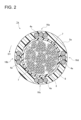
- FIG. FIG. 2 is a cross-sectional view showing an example of an optical fiber cable according to Comparative Example 1.
- FIG. 3 is a cross-sectional view showing an example of an optical fiber cable according to Comparative Example 2.
- An object of the present disclosure is to provide an optical fiber cable that has sufficient extensibility and flexibility and that can suitably prevent expansion and contraction of the cable sheath due to temperature changes.
- each of the plurality of tension member groups includes a plurality of tension members; each of the plurality of tension members are not in contact with each other;
- the plurality of tension member groups are arranged along the circumferential direction of the cable jacket in a cross section perpendicular to the axial direction of the optical fiber cable, Adjacent tension member groups among the plurality of tension member groups are separated from each other, fiber optic cable.
- the plurality of tension member groups are arranged inside the cable jacket, it is possible to sufficiently ensure the straightness of the optical fiber cable.
- the adjacent tension member groups are separated from each other, it is possible to improve the bendability (flexibility) of the optical fiber cable.
- "adjacent tension member groups are separated from each other” means that when the tension member groups are viewed as one group, there is a gap between the adjacent tension member groups. It means that D>d in FIG. Further, if the tension members are in contact with each other, the contact area between the cable jacket and the tension members is reduced, so the effect of suppressing expansion and contraction of the cable jacket is reduced.
- each tension member can suitably prevent the expansion and contraction of the cable sheath due to the temperature change. Therefore, it is possible to provide an optical fiber cable that has sufficient extensibility and flexibility and that can suitably prevent expansion and contraction of the cable sheath due to temperature changes.
- each tension member prevents the cable jacket from changing due to temperature changes. It is possible to suitably prevent the expansion and contraction of.
- each of the plurality of tension member groups includes three or more tension members.
- FIG. 1 is a cross-sectional view showing an optical fiber cable 1 according to this embodiment.
- the cross section of the optical fiber cable 1 shown in FIG. 1 is a cross section perpendicular to the axial direction of the optical fiber cable 1 .
- the optical fiber cable 1 includes a plurality of optical fiber core wires 3, a water absorbing tape 8, a tear string 7, a cable jacket 5, and a plurality of tension member groups 6a-6d.
- the outer diameter of the optical fiber cable 1 is, for example, within the range of 5 mm to 20 mm.
- the optical fiber cable 1 is, for example, an optical fiber cable for pneumatic feeding that is pneumatically fed through a duct such as a microduct.
- a plurality of optical fiber core wires 3 are housed in a housing space 10 for the optical fiber cable 1 .
- a plurality of optical fiber core wires 3 extend along the axial direction of the optical fiber cable 1 .
- the plurality of optical fibers 3 may be helically twisted along the axial direction.
- the optical fiber cable 3 has a glass fiber and a resin coating covering the glass fiber.
- a glass fiber has at least one core through which signal light propagates and a clad covering the core. The refractive index of the core is greater than that of the cladding.
- the optical fiber tape core wire is, for example, an intermittent bonding type optical fiber tape in which adjacent optical fiber core wires among a plurality of optical fiber core wires arranged in parallel are intermittently bonded along the axial direction. It may be a core wire.
- a plurality of optical fiber tape core wires may be helically twisted along the axial direction of the optical fiber cable 1 .
- the water absorbing tape 8 is wound around the entire plurality of optical fiber core wires 3, for example, vertically or horizontally.
- the water-absorbing tape 8 is made by attaching water-absorbing powder to a base fabric made of polyester or the like, for example, to give water-absorbing processing.
- the tear string 7 is for tearing the cable jacket 5 and is embedded in the cable jacket 5 . In this example, two tear strings 7 are provided within the optical fiber cable 1 . By pulling out the tear string 7, the cable jacket 5 can be torn in the axial direction (longitudinal direction), and as a result, the optical fiber core wire 3 can be taken out.
- the tear string 7 is made of, for example, a plastic material (eg, polyester) that is resistant to tension.
- the cable jacket 5 is provided so as to cover the periphery of the multiple optical fiber core wires 3 .
- the cable jacket 5 is made of resin such as polyvinyl chloride (PVC) or polyethylene (PE).
- the resin of the cable jacket 5 preferably has a Young's modulus of 500 MPa or more.
- the cable jacket 5 contains a silicon-based lubricant.
- the silicon-based lubricant is contained, for example, at a ratio of 2 wt % or more, preferably 3 wt % or more and 5 wt % or less.
- the cable jacket 5 is preferably made of a highly flame-retardant resin.
- the cable jacket 5 is made of, for example, flame-retardant PVC or flame-retardant polyethylene having an oxygen index of 50 or more.
- the optical fiber cable 1 conforms to the UL1666 riser grade of the North American NEC (National Electrical Code) standard and the Cca class of the European CPR (Construction Products Regulation) standard.
- the cable jacket 5 is, for example, a thermoplastic resin, and is formed by extruding the resin onto the plurality of optical fiber core wires 3 around which the water absorbing tape 8 is wound.
- the four tension member groups 6a-6d are embedded in the cable jacket 5.
- the tension member groups 6a to 6d are arranged along the circumferential direction D1 of the cable jacket 5 in the cross section of the optical fiber cable 1 in FIG.
- the tension member groups 6a-6d may be arranged at regular intervals along the circumferential direction D1.
- Each of the tension member groups 6a-6d has three tension members 4.
- the tension member groups 6a to 6d may be collectively referred to as the tension member group 6 in some cases.
- the tension member 4 is made of a tensile strength material.
- the tension member 4 may be made of fiber-reinforced plastic (FRP) such as aramid FRP, glass FRP, or carbon FRP.
- FRP fiber-reinforced plastic
- Each tension member 4 has a circular cross section.
- the outer diameter R of each tension member 4 is, for example, within the range of 0.2 mm to 2 mm.
- Each tension member 4 extends along the axial direction of the optical fiber cable 1 .
- the tension members 4 included in the tension member groups 6a-6d are not in contact with each other. In this regard, the shortest distance d between adjacent tension members 4 is 0.05 mm or more.
- the shortest distance d between adjacent tension members 4 is different from the shortest distance D between adjacent tension member groups 6 . More specifically, the shortest distance d between adjacent tension members 4 is smaller than the shortest distance D between adjacent tension member groups 6 .
- the shortest distance between adjacent tension members is smaller than the shortest distance between adjacent tension member groups. It will be. That is, a group composed of some of the plurality of tension members 4 arranged at equal intervals along the circumferential direction D1 as shown in FIG. 3 corresponds to the tension member group defined in this embodiment. Note that we do not.
- Adjacent tension member groups among the tension member groups 6a to 6d are separated from each other. As shown in FIG. 1, the shortest distance D between the adjacent tension member groups 6a and 6d satisfies the condition D>3R (as described above, R indicates the outer diameter of the tension member 4).
- the tension member groups 6a to 6d are arranged at the same intervals along the circumferential direction D1
- the shortest distance between the adjacent tension member groups 6a and 6b is the same as the adjacent tension member group 6b.
- 6c and the shortest distance between the adjacent tension member groups 6c and 6d are similarly D.
- the tension member groups 6a to 6d do not necessarily have to be arranged at the same intervals along the circumferential direction D1.
- the shortest distance D between any two adjacent tension member groups 6 among the four tension member groups 6a to 6d is It satisfies the condition of D>3R.
- the four tension member groups 6a to 6d are arranged inside the cable jacket 5, so the straightness of the optical fiber cable 1 can be sufficiently ensured. .
- the adjacent tension member groups 6 are separated from each other, the ease of bending (flexibility) of the optical fiber cable 1 can be improved.
- the shortest distance D between the adjacent tension member groups 6 satisfies the condition D>3R, the flexibility of the optical fiber cable 1 can be improved while sufficiently securing the straightness of the optical fiber cable 1 . It becomes possible.
- each tension member group 6 when the tension members 4 included in each tension member group 6 are in contact with each other, the contact area between the cable jacket 5 and the tension member 4 is reduced, so that the effect of suppressing expansion and contraction of the cable jacket 5 is obtained. decrease.
- the tension members 4 since the tension members 4 are not in contact with each other, deterioration in adhesion between the tension members 4 and the cable jacket 5 is prevented.
- the shortest distance d between the adjacent tension members 4 is 0.05 mm or more, the adhesion between each tension member 4 and the cable jacket 5 is sufficiently ensured. Therefore, it is possible to suitably prevent the cable jacket 5 from expanding and contracting due to temperature changes caused by the tension members 4 .
- the optical fiber cable 1 which has sufficient straightness and flexibility and which can suitably prevent the expansion and contraction of the cable jacket 5 due to temperature changes.
- the optical fiber cable 1 according to this embodiment has sufficient flexibility and flexibility, and is therefore suitable as an optical fiber cable for pneumatic feeding.
- the adhesion between the tension members 4 and the cable jacket 5 is 9.8 N/cm or more. It is confirmed that Since the adhesion force between the tension member 4 and the cable jacket 5 is 9.8 N/cm or more, expansion and contraction of the cable jacket 5 can be suitably prevented, and the optical fiber cable 1 can be operated in a low temperature environment. It is also possible to prevent an increase in the transmission loss of
- the tension member groups 6a to 6d are arranged at equal intervals along the circumferential direction D1, it is possible to suitably prevent the optical fiber cable 1 from being bent in a specific direction. is possible, and the optical fiber cable 1 can be suitably pneumatically fed into the duct.
- each tension member group 6 includes three tension members 4, but the number of tension members 4 included in each tension member group 6 is not particularly limited. In this regard, when three or more tension members 4 are included in each tension member group 6, the straightness of the optical fiber cable 1 is further improved.
- an optical fiber cable 1a according to Comparative Example 1 and an optical fiber cable 1b according to Comparative Example 2 will be briefly described with reference to FIGS.
- FIG. 2 in the optical fiber cable 1a according to Comparative Example 1, four tension member groups 16a to 16d are arranged at equal intervals along the circumferential direction D1 of the cable jacket 5a. Each tension member 4a included in the member groups 16a to 16d is in contact with each other.
- the tension members 4b are not arranged in the cable jacket 5b in a state of forming a group. That is, 12 tension members 4b are arranged at regular intervals along the circumferential direction D1 of the cable jacket 5b.
- each tension member 4a included in each tension member group 16a to 16d is in contact with another tension member 4a.
- the adhesion between each tension member 4 and the cable jacket 5 is weakened. Therefore, the effect of suppressing expansion and contraction of the cable jacket 5a is reduced.
- each of the optical fiber cables 1, 1a, 1b Stiffness values were actually measured.
- the method for measuring the stiffness value conforms to IEC60794 Stiffness (Method E17A).
- the stiffness value of the optical fiber cable 1 was 2.3 N ⁇ m 2 and the stiffness value of the optical fiber cable 1a was 2.2 N ⁇ m 2 .
- the stiffness value of the optical fiber cable 1b was 3.1 N ⁇ m 2 .
- the optical fiber cable 1b shown in FIG. 3 has a significantly higher rigidity value than the optical fiber cable 1 shown in FIG. 1, and the flexibility of the optical fiber cable 1b is reduced. . If the optical fiber cable has a high rigidity value, the storability of the optical fiber cable is reduced, making it difficult to handle the optical fiber cable.
- the stiffness value of the optical fiber cable 1 is 2.3 N ⁇ m 2 , it is understood that the optical fiber cable 1 has both sufficient extensibility and flexibility.
- the distance between the adjacent tension member groups 6 is sufficiently large (specifically, the shortest distance D between the adjacent tension member groups 6 satisfies the condition D>3R), the rigidity of the optical fiber cable 1 is increased. It is understood that the value is lower than the stiffness value of the optical fiber cable 1b.
Landscapes
- Physics & Mathematics (AREA)
- General Physics & Mathematics (AREA)
- Optics & Photonics (AREA)
- Light Guides In General And Applications Therefor (AREA)
Priority Applications (3)
| Application Number | Priority Date | Filing Date | Title |
|---|---|---|---|
| JP2023569438A JPWO2023120483A1 (https=) | 2021-12-20 | 2022-12-19 | |
| EP22911185.1A EP4455750A4 (en) | 2021-12-20 | 2022-12-19 | FIBER OPTIC CABLE |
| US18/552,224 US20240176089A1 (en) | 2021-12-20 | 2022-12-19 | Optical fiber cable |
Applications Claiming Priority (2)
| Application Number | Priority Date | Filing Date | Title |
|---|---|---|---|
| JP2021206242 | 2021-12-20 | ||
| JP2021-206242 | 2021-12-20 |
Publications (1)
| Publication Number | Publication Date |
|---|---|
| WO2023120483A1 true WO2023120483A1 (ja) | 2023-06-29 |
Family
ID=86902468
Family Applications (1)
| Application Number | Title | Priority Date | Filing Date |
|---|---|---|---|
| PCT/JP2022/046686 Ceased WO2023120483A1 (ja) | 2021-12-20 | 2022-12-19 | 光ファイバケーブル |
Country Status (4)
| Country | Link |
|---|---|
| US (1) | US20240176089A1 (https=) |
| EP (1) | EP4455750A4 (https=) |
| JP (1) | JPWO2023120483A1 (https=) |
| WO (1) | WO2023120483A1 (https=) |
Citations (9)
| Publication number | Priority date | Publication date | Assignee | Title |
|---|---|---|---|---|
| JPH02155122A (ja) * | 1988-09-29 | 1990-06-14 | American Teleph & Telegr Co <Att> | 通信ケーブル |
| US20060127016A1 (en) * | 2004-12-15 | 2006-06-15 | Baird Paul R | Fiber optic cables with easy access features |
| CN104765118A (zh) * | 2015-04-23 | 2015-07-08 | 龚利芬 | 防水松套管及使用该松套管的光缆 |
| WO2015195095A1 (en) * | 2014-06-17 | 2015-12-23 | Prysmian S.P.A. | Central-tube optical-fiber cable |
| JP2016533526A (ja) * | 2013-10-18 | 2016-10-27 | コーニング オプティカル コミュニケーションズ リミテッド ライアビリティ カンパニー | 補強材付き光ファイバケーブル |
| US20190293887A1 (en) * | 2016-11-30 | 2019-09-26 | Corning Optical Communications LLC | Low attenuation optical fiber cable with small sized active particles |
| JP2020204752A (ja) | 2019-06-19 | 2020-12-24 | 住友電気工業株式会社 | 光ファイバケーブル |
| EP3800493A1 (en) * | 2019-10-01 | 2021-04-07 | Sterlite Technologies Limited | Flexible central tube ribbon optical fiber cable |
| WO2021117843A1 (en) * | 2019-12-11 | 2021-06-17 | Fujikura Ltd. | Optical fiber cable |
Family Cites Families (29)
| Publication number | Priority date | Publication date | Assignee | Title |
|---|---|---|---|---|
| US4723831A (en) * | 1985-12-02 | 1988-02-09 | American Telephone And Telegraph Company At&T Bell Laboratories | Optical fiber communications cable |
| US4844575A (en) * | 1987-04-10 | 1989-07-04 | American Telephone And Telegraph Company, At&T Bell Laboratories | Optical fiber cable |
| US4892382A (en) * | 1988-09-26 | 1990-01-09 | Siecor Corporation | Dielectric optical drop cable |
| US5109457A (en) * | 1988-12-14 | 1992-04-28 | At&T Bell Laboratories | All-dielectric optical fiber cable having enhanced fiber access |
| FR2736730B1 (fr) * | 1995-07-13 | 1997-08-22 | Silec Liaisons Elec | Cable comportant des fibres optiques entourees par une gaine exterieure |
| DE19717313A1 (de) * | 1997-04-24 | 1998-11-05 | Alsthom Cge Alcatel | Optisches Kabel und Verfahren zum Herstellen eines optischen Kabels |
| FR2764709B1 (fr) * | 1997-06-16 | 1999-07-23 | Alsthom Cge Alcatel | Cable a fibres optiques thermoplastique |
| US6101305A (en) * | 1997-12-15 | 2000-08-08 | Siecor Corporation | Fiber optic cable |
| US6259844B1 (en) * | 1997-12-15 | 2001-07-10 | Siecor Operations, Llc | Strengthened fiber optic cable |
| FR2778753B1 (fr) * | 1998-05-18 | 2002-06-07 | Sat Sa De Telecomm | Cable comportant des fibres optiques entourees par une gaine a renforts longitudinaux |
| US6192178B1 (en) * | 1999-03-31 | 2001-02-20 | Siecor Operations, Llc | Fiber optic cable with profiled group of optical fibers |
| KR100442605B1 (ko) * | 2002-03-04 | 2004-08-02 | 삼성전자주식회사 | 소형 경량 광케이블 |
| US6970629B2 (en) * | 2002-12-19 | 2005-11-29 | Corning Cable Systems Llc | Optical tube assembly having a dry insert and methods of making the same |
| US9360647B2 (en) * | 2009-02-06 | 2016-06-07 | Draka Comteq, B.V. | Central-tube cable with high-conductivity conductors encapsulated with high-dielectric-strength insulation |
| BRPI0924635A2 (pt) * | 2009-03-16 | 2016-03-08 | Prysmian Spa | "cabo óptico." |
| CA2769324A1 (en) * | 2009-07-31 | 2011-02-03 | Corning Cable Systems Llc | Optical fiber cables |
| ES2731696T3 (es) * | 2011-08-04 | 2019-11-18 | Cable de derivación de fibra óptica con un riesgo de incendio reducido | |
| JP6286832B2 (ja) * | 2013-02-01 | 2018-03-07 | 住友電気工業株式会社 | 光ケーブル |
| US10167396B2 (en) * | 2017-05-03 | 2019-01-01 | Corning Incorporated | Low smoke fire-resistant optical ribbon |
| WO2019010291A1 (en) * | 2017-07-05 | 2019-01-10 | Corning Research & Development Corporation | FLAT CABLE WITH HIGH DENSITY OF FIBERS |
| US11175471B2 (en) * | 2018-02-14 | 2021-11-16 | Sterlite Technologies Limited | Predefined cylindrical enclosure for optical waveguide cable |
| WO2020092189A1 (en) * | 2018-11-02 | 2020-05-07 | Corning Research & Development Corporation | Flexible, non -preferential bend jackets for optical fiber cables |
| WO2020256019A1 (ja) * | 2019-06-19 | 2020-12-24 | 住友電気工業株式会社 | 光ファイバケーブル |
| EP3772667A1 (en) * | 2019-08-07 | 2021-02-10 | Sterlite Technologies Limited | Cable with interstitial fillers and edge ribbons |
| US20210063661A1 (en) * | 2019-08-30 | 2021-03-04 | Sterlite Technologies Limited | Bendable optical fibre cable |
| JPWO2022004666A1 (https=) * | 2020-06-29 | 2022-01-06 | ||
| CN116075760A (zh) * | 2020-09-02 | 2023-05-05 | 株式会社藤仓 | 光缆以及光缆制造方法 |
| WO2022065485A1 (ja) * | 2020-09-28 | 2022-03-31 | 住友電気工業株式会社 | 光ファイバケーブルおよびコネクタ付きケーブル |
| CN117337405A (zh) * | 2021-05-31 | 2024-01-02 | 日本电信电话株式会社 | 光纤线缆以及光纤线缆制造装置 |
-
2022
- 2022-12-19 US US18/552,224 patent/US20240176089A1/en active Pending
- 2022-12-19 WO PCT/JP2022/046686 patent/WO2023120483A1/ja not_active Ceased
- 2022-12-19 EP EP22911185.1A patent/EP4455750A4/en active Pending
- 2022-12-19 JP JP2023569438A patent/JPWO2023120483A1/ja active Pending
Patent Citations (9)
| Publication number | Priority date | Publication date | Assignee | Title |
|---|---|---|---|---|
| JPH02155122A (ja) * | 1988-09-29 | 1990-06-14 | American Teleph & Telegr Co <Att> | 通信ケーブル |
| US20060127016A1 (en) * | 2004-12-15 | 2006-06-15 | Baird Paul R | Fiber optic cables with easy access features |
| JP2016533526A (ja) * | 2013-10-18 | 2016-10-27 | コーニング オプティカル コミュニケーションズ リミテッド ライアビリティ カンパニー | 補強材付き光ファイバケーブル |
| WO2015195095A1 (en) * | 2014-06-17 | 2015-12-23 | Prysmian S.P.A. | Central-tube optical-fiber cable |
| CN104765118A (zh) * | 2015-04-23 | 2015-07-08 | 龚利芬 | 防水松套管及使用该松套管的光缆 |
| US20190293887A1 (en) * | 2016-11-30 | 2019-09-26 | Corning Optical Communications LLC | Low attenuation optical fiber cable with small sized active particles |
| JP2020204752A (ja) | 2019-06-19 | 2020-12-24 | 住友電気工業株式会社 | 光ファイバケーブル |
| EP3800493A1 (en) * | 2019-10-01 | 2021-04-07 | Sterlite Technologies Limited | Flexible central tube ribbon optical fiber cable |
| WO2021117843A1 (en) * | 2019-12-11 | 2021-06-17 | Fujikura Ltd. | Optical fiber cable |
Non-Patent Citations (1)
| Title |
|---|
| See also references of EP4455750A4 |
Also Published As
| Publication number | Publication date |
|---|---|
| EP4455750A4 (en) | 2025-04-16 |
| EP4455750A1 (en) | 2024-10-30 |
| US20240176089A1 (en) | 2024-05-30 |
| JPWO2023120483A1 (https=) | 2023-06-29 |
Similar Documents
| Publication | Publication Date | Title |
|---|---|---|
| EP3879323B1 (en) | Optical fiber cable | |
| US12535645B2 (en) | Optical fiber cable and cable with connector | |
| US4093342A (en) | Optical fiber cable | |
| WO2017022531A1 (ja) | 光ファイバケーブル | |
| US11994730B2 (en) | Optical fiber cable | |
| US11194108B2 (en) | Slot-type optical cable | |
| JP6542648B2 (ja) | 光ファイバケーブル | |
| JP5840911B2 (ja) | 光ファイバケーブル | |
| WO2023120483A1 (ja) | 光ファイバケーブル | |
| JPWO2012036031A1 (ja) | プラスチック光ファイバユニット、およびそれを用いたプラスチック光ファイバケーブル | |
| WO2022065485A1 (ja) | 光ファイバケーブルおよびコネクタ付きケーブル | |
| WO2021241485A1 (ja) | 光ファイバユニット、光ファイバケーブル、コネクタ付きケーブル及び光ファイバユニットの接続方法 | |
| CN217506224U (zh) | 一种金属编织保护网光缆 | |
| EP4451028A1 (en) | Optical fiber cable | |
| WO2023002971A1 (ja) | 光ファイバケーブル | |
| EP4089457A1 (en) | Multi-fiber optical cable | |
| JP7852654B2 (ja) | 光ファイバケーブル | |
| JP2004212960A (ja) | 光ファイバケーブル | |
| WO2025135055A1 (ja) | 光ファイバケーブル | |
| JP2009145796A (ja) | 光ケーブル | |
| JP2021060438A (ja) | 光ファイバケーブル | |
| JP2009145794A (ja) | 光ケーブル | |
| JP6056295B2 (ja) | 光ドロップケーブル | |
| JP2025077224A (ja) | 光ファイバケーブル | |
| JP4002237B2 (ja) | 光ファイバケーブル |
Legal Events
| Date | Code | Title | Description |
|---|---|---|---|
| 121 | Ep: the epo has been informed by wipo that ep was designated in this application |
Ref document number: 22911185 Country of ref document: EP Kind code of ref document: A1 |
|
| WWE | Wipo information: entry into national phase |
Ref document number: 18552224 Country of ref document: US |
|
| WWE | Wipo information: entry into national phase |
Ref document number: 2023569438 Country of ref document: JP |
|
| NENP | Non-entry into the national phase |
Ref country code: DE |
|
| ENP | Entry into the national phase |
Ref document number: 2022911185 Country of ref document: EP Effective date: 20240722 |