WO2023120483A1 - 光ファイバケーブル - Google Patents
光ファイバケーブル Download PDFInfo
- Publication number
- WO2023120483A1 WO2023120483A1 PCT/JP2022/046686 JP2022046686W WO2023120483A1 WO 2023120483 A1 WO2023120483 A1 WO 2023120483A1 JP 2022046686 W JP2022046686 W JP 2022046686W WO 2023120483 A1 WO2023120483 A1 WO 2023120483A1
- Authority
- WO
- WIPO (PCT)
- Prior art keywords
- optical fiber
- tension member
- cable
- member groups
- fiber cable
- Prior art date
Links
- 239000013307 optical fiber Substances 0.000 title claims abstract description 109
- 239000000835 fiber Substances 0.000 claims description 5
- 230000008602 contraction Effects 0.000 description 10
- 230000000052 comparative effect Effects 0.000 description 6
- 229920002430 Fibre-reinforced plastic Polymers 0.000 description 5
- 230000000694 effects Effects 0.000 description 5
- 239000011151 fibre-reinforced plastic Substances 0.000 description 5
- 229920005989 resin Polymers 0.000 description 5
- 239000011347 resin Substances 0.000 description 5
- XLYOFNOQVPJJNP-UHFFFAOYSA-N water Substances O XLYOFNOQVPJJNP-UHFFFAOYSA-N 0.000 description 4
- RNFJDJUURJAICM-UHFFFAOYSA-N 2,2,4,4,6,6-hexaphenoxy-1,3,5-triaza-2$l^{5},4$l^{5},6$l^{5}-triphosphacyclohexa-1,3,5-triene Chemical compound N=1P(OC=2C=CC=CC=2)(OC=2C=CC=CC=2)=NP(OC=2C=CC=CC=2)(OC=2C=CC=CC=2)=NP=1(OC=1C=CC=CC=1)OC1=CC=CC=C1 RNFJDJUURJAICM-UHFFFAOYSA-N 0.000 description 3
- 239000004698 Polyethylene Substances 0.000 description 3
- 230000004308 accommodation Effects 0.000 description 3
- 239000003063 flame retardant Substances 0.000 description 3
- 239000003365 glass fiber Substances 0.000 description 3
- 229920000573 polyethylene Polymers 0.000 description 3
- XUIMIQQOPSSXEZ-UHFFFAOYSA-N Silicon Chemical compound [Si] XUIMIQQOPSSXEZ-UHFFFAOYSA-N 0.000 description 2
- 230000005540 biological transmission Effects 0.000 description 2
- 230000006866 deterioration Effects 0.000 description 2
- 239000000314 lubricant Substances 0.000 description 2
- 239000000463 material Substances 0.000 description 2
- 238000000034 method Methods 0.000 description 2
- 229920000728 polyester Polymers 0.000 description 2
- -1 polyethylene Polymers 0.000 description 2
- 239000004800 polyvinyl chloride Substances 0.000 description 2
- 229910052710 silicon Inorganic materials 0.000 description 2
- 239000010703 silicon Substances 0.000 description 2
- OKTJSMMVPCPJKN-UHFFFAOYSA-N Carbon Chemical compound [C] OKTJSMMVPCPJKN-UHFFFAOYSA-N 0.000 description 1
- 102220466178 Hypoxia-inducible lipid droplet-associated protein_E17A_mutation Human genes 0.000 description 1
- 238000010521 absorption reaction Methods 0.000 description 1
- 239000004760 aramid Substances 0.000 description 1
- 229920003235 aromatic polyamide Polymers 0.000 description 1
- QVGXLLKOCUKJST-UHFFFAOYSA-N atomic oxygen Chemical compound [O] QVGXLLKOCUKJST-UHFFFAOYSA-N 0.000 description 1
- 238000005452 bending Methods 0.000 description 1
- 230000033228 biological regulation Effects 0.000 description 1
- 229910052799 carbon Inorganic materials 0.000 description 1
- 238000005253 cladding Methods 0.000 description 1
- 239000011248 coating agent Substances 0.000 description 1
- 238000000576 coating method Methods 0.000 description 1
- 238000010276 construction Methods 0.000 description 1
- 239000004744 fabric Substances 0.000 description 1
- 239000011521 glass Substances 0.000 description 1
- 238000005259 measurement Methods 0.000 description 1
- 238000012986 modification Methods 0.000 description 1
- 230000004048 modification Effects 0.000 description 1
- 229910052760 oxygen Inorganic materials 0.000 description 1
- 239000001301 oxygen Substances 0.000 description 1
- 229920003023 plastic Polymers 0.000 description 1
- 239000004033 plastic Substances 0.000 description 1
- 229920000915 polyvinyl chloride Polymers 0.000 description 1
- 239000000843 powder Substances 0.000 description 1
- 238000005086 pumping Methods 0.000 description 1
- 229920005992 thermoplastic resin Polymers 0.000 description 1
Images


Classifications
-
- G—PHYSICS
- G02—OPTICS
- G02B—OPTICAL ELEMENTS, SYSTEMS OR APPARATUS
- G02B6/00—Light guides; Structural details of arrangements comprising light guides and other optical elements, e.g. couplings
- G02B6/44—Mechanical structures for providing tensile strength and external protection for fibres, e.g. optical transmission cables
Definitions
- Patent Document 1 discloses an optical fiber cable that is laid by air-pumping the inside of a duct.
- a fiber optic cable includes: a plurality of optical fiber core wires; a cable jacket covering the plurality of optical fibers; a plurality of tension member groups embedded within the cable jacket, comprising: each of the plurality of tension member groups includes a plurality of tension members; each of the plurality of tension members are not in contact with each other; The plurality of tension member groups are arranged along the circumferential direction of the cable jacket in a cross section perpendicular to the axial direction of the optical fiber cable, Adjacent tension member groups among the plurality of tension member groups are separated from each other.
- FIG. 1 is a cross-sectional view showing a fiber optic cable according to an embodiment of the present disclosure
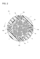
- FIG. FIG. 2 is a cross-sectional view showing an example of an optical fiber cable according to Comparative Example 1.
- FIG. 3 is a cross-sectional view showing an example of an optical fiber cable according to Comparative Example 2.
- An object of the present disclosure is to provide an optical fiber cable that has sufficient extensibility and flexibility and that can suitably prevent expansion and contraction of the cable sheath due to temperature changes.
- each of the plurality of tension member groups includes a plurality of tension members; each of the plurality of tension members are not in contact with each other;
- the plurality of tension member groups are arranged along the circumferential direction of the cable jacket in a cross section perpendicular to the axial direction of the optical fiber cable, Adjacent tension member groups among the plurality of tension member groups are separated from each other, fiber optic cable.
- the plurality of tension member groups are arranged inside the cable jacket, it is possible to sufficiently ensure the straightness of the optical fiber cable.
- the adjacent tension member groups are separated from each other, it is possible to improve the bendability (flexibility) of the optical fiber cable.
- "adjacent tension member groups are separated from each other” means that when the tension member groups are viewed as one group, there is a gap between the adjacent tension member groups. It means that D>d in FIG. Further, if the tension members are in contact with each other, the contact area between the cable jacket and the tension members is reduced, so the effect of suppressing expansion and contraction of the cable jacket is reduced.
- each tension member can suitably prevent the expansion and contraction of the cable sheath due to the temperature change. Therefore, it is possible to provide an optical fiber cable that has sufficient extensibility and flexibility and that can suitably prevent expansion and contraction of the cable sheath due to temperature changes.
- each tension member prevents the cable jacket from changing due to temperature changes. It is possible to suitably prevent the expansion and contraction of.
- each of the plurality of tension member groups includes three or more tension members.
- FIG. 1 is a cross-sectional view showing an optical fiber cable 1 according to this embodiment.
- the cross section of the optical fiber cable 1 shown in FIG. 1 is a cross section perpendicular to the axial direction of the optical fiber cable 1 .
- the optical fiber cable 1 includes a plurality of optical fiber core wires 3, a water absorbing tape 8, a tear string 7, a cable jacket 5, and a plurality of tension member groups 6a-6d.
- the outer diameter of the optical fiber cable 1 is, for example, within the range of 5 mm to 20 mm.
- the optical fiber cable 1 is, for example, an optical fiber cable for pneumatic feeding that is pneumatically fed through a duct such as a microduct.
- a plurality of optical fiber core wires 3 are housed in a housing space 10 for the optical fiber cable 1 .
- a plurality of optical fiber core wires 3 extend along the axial direction of the optical fiber cable 1 .
- the plurality of optical fibers 3 may be helically twisted along the axial direction.
- the optical fiber cable 3 has a glass fiber and a resin coating covering the glass fiber.
- a glass fiber has at least one core through which signal light propagates and a clad covering the core. The refractive index of the core is greater than that of the cladding.
- the optical fiber tape core wire is, for example, an intermittent bonding type optical fiber tape in which adjacent optical fiber core wires among a plurality of optical fiber core wires arranged in parallel are intermittently bonded along the axial direction. It may be a core wire.
- a plurality of optical fiber tape core wires may be helically twisted along the axial direction of the optical fiber cable 1 .
- the water absorbing tape 8 is wound around the entire plurality of optical fiber core wires 3, for example, vertically or horizontally.
- the water-absorbing tape 8 is made by attaching water-absorbing powder to a base fabric made of polyester or the like, for example, to give water-absorbing processing.
- the tear string 7 is for tearing the cable jacket 5 and is embedded in the cable jacket 5 . In this example, two tear strings 7 are provided within the optical fiber cable 1 . By pulling out the tear string 7, the cable jacket 5 can be torn in the axial direction (longitudinal direction), and as a result, the optical fiber core wire 3 can be taken out.
- the tear string 7 is made of, for example, a plastic material (eg, polyester) that is resistant to tension.
- the cable jacket 5 is provided so as to cover the periphery of the multiple optical fiber core wires 3 .
- the cable jacket 5 is made of resin such as polyvinyl chloride (PVC) or polyethylene (PE).
- the resin of the cable jacket 5 preferably has a Young's modulus of 500 MPa or more.
- the cable jacket 5 contains a silicon-based lubricant.
- the silicon-based lubricant is contained, for example, at a ratio of 2 wt % or more, preferably 3 wt % or more and 5 wt % or less.
- the cable jacket 5 is preferably made of a highly flame-retardant resin.
- the cable jacket 5 is made of, for example, flame-retardant PVC or flame-retardant polyethylene having an oxygen index of 50 or more.
- the optical fiber cable 1 conforms to the UL1666 riser grade of the North American NEC (National Electrical Code) standard and the Cca class of the European CPR (Construction Products Regulation) standard.
- the cable jacket 5 is, for example, a thermoplastic resin, and is formed by extruding the resin onto the plurality of optical fiber core wires 3 around which the water absorbing tape 8 is wound.
- the four tension member groups 6a-6d are embedded in the cable jacket 5.
- the tension member groups 6a to 6d are arranged along the circumferential direction D1 of the cable jacket 5 in the cross section of the optical fiber cable 1 in FIG.
- the tension member groups 6a-6d may be arranged at regular intervals along the circumferential direction D1.
- Each of the tension member groups 6a-6d has three tension members 4.
- the tension member groups 6a to 6d may be collectively referred to as the tension member group 6 in some cases.
- the tension member 4 is made of a tensile strength material.
- the tension member 4 may be made of fiber-reinforced plastic (FRP) such as aramid FRP, glass FRP, or carbon FRP.
- FRP fiber-reinforced plastic
- Each tension member 4 has a circular cross section.
- the outer diameter R of each tension member 4 is, for example, within the range of 0.2 mm to 2 mm.
- Each tension member 4 extends along the axial direction of the optical fiber cable 1 .
- the tension members 4 included in the tension member groups 6a-6d are not in contact with each other. In this regard, the shortest distance d between adjacent tension members 4 is 0.05 mm or more.
- the shortest distance d between adjacent tension members 4 is different from the shortest distance D between adjacent tension member groups 6 . More specifically, the shortest distance d between adjacent tension members 4 is smaller than the shortest distance D between adjacent tension member groups 6 .
- the shortest distance between adjacent tension members is smaller than the shortest distance between adjacent tension member groups. It will be. That is, a group composed of some of the plurality of tension members 4 arranged at equal intervals along the circumferential direction D1 as shown in FIG. 3 corresponds to the tension member group defined in this embodiment. Note that we do not.
- Adjacent tension member groups among the tension member groups 6a to 6d are separated from each other. As shown in FIG. 1, the shortest distance D between the adjacent tension member groups 6a and 6d satisfies the condition D>3R (as described above, R indicates the outer diameter of the tension member 4).
- the tension member groups 6a to 6d are arranged at the same intervals along the circumferential direction D1
- the shortest distance between the adjacent tension member groups 6a and 6b is the same as the adjacent tension member group 6b.
- 6c and the shortest distance between the adjacent tension member groups 6c and 6d are similarly D.
- the tension member groups 6a to 6d do not necessarily have to be arranged at the same intervals along the circumferential direction D1.
- the shortest distance D between any two adjacent tension member groups 6 among the four tension member groups 6a to 6d is It satisfies the condition of D>3R.
- the four tension member groups 6a to 6d are arranged inside the cable jacket 5, so the straightness of the optical fiber cable 1 can be sufficiently ensured. .
- the adjacent tension member groups 6 are separated from each other, the ease of bending (flexibility) of the optical fiber cable 1 can be improved.
- the shortest distance D between the adjacent tension member groups 6 satisfies the condition D>3R, the flexibility of the optical fiber cable 1 can be improved while sufficiently securing the straightness of the optical fiber cable 1 . It becomes possible.
- each tension member group 6 when the tension members 4 included in each tension member group 6 are in contact with each other, the contact area between the cable jacket 5 and the tension member 4 is reduced, so that the effect of suppressing expansion and contraction of the cable jacket 5 is obtained. decrease.
- the tension members 4 since the tension members 4 are not in contact with each other, deterioration in adhesion between the tension members 4 and the cable jacket 5 is prevented.
- the shortest distance d between the adjacent tension members 4 is 0.05 mm or more, the adhesion between each tension member 4 and the cable jacket 5 is sufficiently ensured. Therefore, it is possible to suitably prevent the cable jacket 5 from expanding and contracting due to temperature changes caused by the tension members 4 .
- the optical fiber cable 1 which has sufficient straightness and flexibility and which can suitably prevent the expansion and contraction of the cable jacket 5 due to temperature changes.
- the optical fiber cable 1 according to this embodiment has sufficient flexibility and flexibility, and is therefore suitable as an optical fiber cable for pneumatic feeding.
- the adhesion between the tension members 4 and the cable jacket 5 is 9.8 N/cm or more. It is confirmed that Since the adhesion force between the tension member 4 and the cable jacket 5 is 9.8 N/cm or more, expansion and contraction of the cable jacket 5 can be suitably prevented, and the optical fiber cable 1 can be operated in a low temperature environment. It is also possible to prevent an increase in the transmission loss of
- the tension member groups 6a to 6d are arranged at equal intervals along the circumferential direction D1, it is possible to suitably prevent the optical fiber cable 1 from being bent in a specific direction. is possible, and the optical fiber cable 1 can be suitably pneumatically fed into the duct.
- each tension member group 6 includes three tension members 4, but the number of tension members 4 included in each tension member group 6 is not particularly limited. In this regard, when three or more tension members 4 are included in each tension member group 6, the straightness of the optical fiber cable 1 is further improved.
- an optical fiber cable 1a according to Comparative Example 1 and an optical fiber cable 1b according to Comparative Example 2 will be briefly described with reference to FIGS.
- FIG. 2 in the optical fiber cable 1a according to Comparative Example 1, four tension member groups 16a to 16d are arranged at equal intervals along the circumferential direction D1 of the cable jacket 5a. Each tension member 4a included in the member groups 16a to 16d is in contact with each other.
- the tension members 4b are not arranged in the cable jacket 5b in a state of forming a group. That is, 12 tension members 4b are arranged at regular intervals along the circumferential direction D1 of the cable jacket 5b.
- each tension member 4a included in each tension member group 16a to 16d is in contact with another tension member 4a.
- the adhesion between each tension member 4 and the cable jacket 5 is weakened. Therefore, the effect of suppressing expansion and contraction of the cable jacket 5a is reduced.
- each of the optical fiber cables 1, 1a, 1b Stiffness values were actually measured.
- the method for measuring the stiffness value conforms to IEC60794 Stiffness (Method E17A).
- the stiffness value of the optical fiber cable 1 was 2.3 N ⁇ m 2 and the stiffness value of the optical fiber cable 1a was 2.2 N ⁇ m 2 .
- the stiffness value of the optical fiber cable 1b was 3.1 N ⁇ m 2 .
- the optical fiber cable 1b shown in FIG. 3 has a significantly higher rigidity value than the optical fiber cable 1 shown in FIG. 1, and the flexibility of the optical fiber cable 1b is reduced. . If the optical fiber cable has a high rigidity value, the storability of the optical fiber cable is reduced, making it difficult to handle the optical fiber cable.
- the stiffness value of the optical fiber cable 1 is 2.3 N ⁇ m 2 , it is understood that the optical fiber cable 1 has both sufficient extensibility and flexibility.
- the distance between the adjacent tension member groups 6 is sufficiently large (specifically, the shortest distance D between the adjacent tension member groups 6 satisfies the condition D>3R), the rigidity of the optical fiber cable 1 is increased. It is understood that the value is lower than the stiffness value of the optical fiber cable 1b.
Abstract
本開示は、複数の光ファイバ心線(3)と、前記複数の光ファイバ心線(3)を覆うケーブル外被(5)と、前記ケーブル外被(5)内に埋め込まれた複数のテンション部材群(6a)-(6d)と、を備えた光ファイバケーブル(1)であって、前記複数のテンション部材群(6a)-(6d)の各々は、複数のテンション部材(4)を含み、前記複数のテンション部材(4)の各々は互いに接触しておらず、前記複数のテンション部材群(6a)-(6d)は、前記光ファイバケーブル(1)の軸方向に垂直な断面において、前記ケーブル外被(5)の周方向に沿って配置され、前記複数のテンション部材群(6a)-(6d)のうち隣接するテンション部材群は互いに離れている、光ファイバケーブル(1)に関する。
Description
本開示は、光ファイバケーブルに関する。本出願は、2021年12月20日出願の日本出願第2021-206242号に基づく優先権を主張し、前記日本出願に記載された全ての記載内容を援用するものである。
特許文献1には、ダクト内を空気圧送して布設する光ファイバケーブルが開示されている。
本開示の一態様に係る光ファイバケーブルは、
複数の光ファイバ心線と、
前記複数の光ファイバ心線を覆うケーブル外被と、
前記ケーブル外被内に埋め込まれた複数のテンション部材群と、を備えた光ファイバケーブルであって、
前記複数のテンション部材群の各々は、複数のテンション部材を含み、
前記複数のテンション部材の各々は互いに接触しておらず、
前記複数のテンション部材群は、前記光ファイバケーブルの軸方向に垂直な断面において、前記ケーブル外被の周方向に沿って配置され、
前記複数のテンション部材群のうち隣接するテンション部材群は互いに離れている。
複数の光ファイバ心線と、
前記複数の光ファイバ心線を覆うケーブル外被と、
前記ケーブル外被内に埋め込まれた複数のテンション部材群と、を備えた光ファイバケーブルであって、
前記複数のテンション部材群の各々は、複数のテンション部材を含み、
前記複数のテンション部材の各々は互いに接触しておらず、
前記複数のテンション部材群は、前記光ファイバケーブルの軸方向に垂直な断面において、前記ケーブル外被の周方向に沿って配置され、
前記複数のテンション部材群のうち隣接するテンション部材群は互いに離れている。
[本開示が解決しようとする課題]
空気圧送用の光ファイバケーブルは、細径軽量化のためケーブル外被厚を薄くし、硬質のケーブル外被を用いる場合が多い。かかる場合では、細いテンション部材しかケーブル外被内に埋め込むことができず、光ファイバケーブルの剛性の低下やケーブル外被の線膨張を抑制することが難しい。また、複数本のテンション部材がケーブル外被内に埋め込まれても、テンション部材の配置によっては光ファイバケーブルの伸直性や柔軟性が変化してしまう。
空気圧送用の光ファイバケーブルは、細径軽量化のためケーブル外被厚を薄くし、硬質のケーブル外被を用いる場合が多い。かかる場合では、細いテンション部材しかケーブル外被内に埋め込むことができず、光ファイバケーブルの剛性の低下やケーブル外被の線膨張を抑制することが難しい。また、複数本のテンション部材がケーブル外被内に埋め込まれても、テンション部材の配置によっては光ファイバケーブルの伸直性や柔軟性が変化してしまう。
本開示は、十分な伸直性及び柔軟性を有すると共に、温度変化によるケーブル外被の伸縮を好適に防止可能な光ファイバケーブルを提供することを目的とする。
[本開示の効果]
本開示によれば、十分な伸直性及び柔軟性を有すると共に、温度変化によるケーブル外被の伸縮を好適に防止可能な光ファイバケーブルを提供することができる。
本開示によれば、十分な伸直性及び柔軟性を有すると共に、温度変化によるケーブル外被の伸縮を好適に防止可能な光ファイバケーブルを提供することができる。
[本開示の実施形態の説明]
実施形態の概要を説明する。
(1)複数の光ファイバ心線と、
前記複数の光ファイバ心線を覆うケーブル外被と、
前記ケーブル外被内に埋め込まれた複数のテンション部材群と、を備えた光ファイバケーブルであって、
前記複数のテンション部材群の各々は、複数のテンション部材を含み、
前記複数のテンション部材の各々は互いに接触しておらず、
前記複数のテンション部材群は、前記光ファイバケーブルの軸方向に垂直な断面において、前記ケーブル外被の周方向に沿って配置され、
前記複数のテンション部材群のうち隣接するテンション部材群は互いに離れている、
光ファイバケーブル。
実施形態の概要を説明する。
(1)複数の光ファイバ心線と、
前記複数の光ファイバ心線を覆うケーブル外被と、
前記ケーブル外被内に埋め込まれた複数のテンション部材群と、を備えた光ファイバケーブルであって、
前記複数のテンション部材群の各々は、複数のテンション部材を含み、
前記複数のテンション部材の各々は互いに接触しておらず、
前記複数のテンション部材群は、前記光ファイバケーブルの軸方向に垂直な断面において、前記ケーブル外被の周方向に沿って配置され、
前記複数のテンション部材群のうち隣接するテンション部材群は互いに離れている、
光ファイバケーブル。
上記構成によれば、複数のテンション部材群がケーブル外被内に配置されているので、光ファイバケーブルの伸直性を十分に確保することができる。また、隣接するテンション部材群が互いに離れているので、光ファイバケーブルの曲げ易さ(柔軟性)を向上させることが可能となる。なお、「隣接するテンション部材群が互いに離れている」とは、テンション部材群を一つの群としてみた場合、隣接するテンション部材群との間に隙間がある、という意味であり、具体的には図1においてD>dであることを意味する。また、各テンション部材が互いに接触していると、ケーブル外被とテンション部材との密着面積が減るため、ケーブル外被の伸縮を抑える効果が減少してしまう。上記構成では、各テンション部材が接触していないため、各テンション部材とケーブル外被との間の密着性の低下が防止される。このため、各テンション部材によって温度変化によるケーブル外被の伸縮を好適に防止することが可能となる。したがって、十分な伸直性及び柔軟性を有すると共に、温度変化によるケーブル外被の伸縮を好適に防止可能な光ファイバケーブルを提供することができる。
(2)前記複数のテンション部材群の各々に含まれる前記複数のテンション部材のうち隣接するテンション部材間の最短距離は、0.05mm以上である、項目(1)に記載の光ファイバケーブル。
上記構成によれば、隣接するテンション部材間の最短距離が0.05mm以上あるため、各テンション部材とケーブル外被との間の密着性が十分確保され、各テンション部材によって温度変化によるケーブル外被の伸縮を好適に防止することが可能となる。
(3)前記テンション部材の外径をRとした場合に、前記隣接するテンション部材群の間の最短距離Dは、D>3Rの条件を満たす、項目(1)又は項目(2)に記載の光ファイバケーブル。
上記構成によれば、光ファイバケーブルの伸直性を十分に確保しつつ、光ファイバケーブルの柔軟性を向上させることが可能となる。
(4)前記複数のテンション部材群は、前記ケーブル外被の周方向に沿って等間隔に配置されている、項目(1)から項目(3)のうちいずれか一項に記載の光ファイバケーブル。
上記構成によれば、光ファイバケーブルが特定の方向に曲げられてしまう状況を好適に防ぐことが可能となり、光ファイバケーブルを好適にマイクロダクト等のダクト内に空気圧送することが可能となる。
(5)前記複数のテンション部材群の各々は、三本以上のテンション部材を含む、項目(1)から項目(4)のうちいずれか一項に記載の光ファイバケーブル。
上記構成によれば、光ファイバケーブルの伸直性を向上させることが可能となる。
[実施形態の詳細]
以下、本開示の実施形態(以下、本実施形態という。)に係る光ファイバケーブル1について図1を参照しながら説明する。各図面に示された各部材の寸法は、説明の便宜上、実際の各部材の寸法とは異なる場合がある。
以下、本開示の実施形態(以下、本実施形態という。)に係る光ファイバケーブル1について図1を参照しながら説明する。各図面に示された各部材の寸法は、説明の便宜上、実際の各部材の寸法とは異なる場合がある。
図1は、本実施形態に係る光ファイバケーブル1を示す断面図である。図1に示す光ファイバケーブル1の断面は、光ファイバケーブル1の軸方向に垂直な断面となる。図1に示すように、光ファイバケーブル1は、複数の光ファイバ心線3と、吸水テープ8と、引裂紐7と、ケーブル外被5と、複数のテンション部材群6a~6dとを備える。光ファイバケーブル1の外径は、例えば、5mmから20mmの範囲内である。
光ファイバケーブル1は、例えば、マイクロダクト等のダクト内を空気圧送される空気圧送用の光ファイバケーブルである。複数本の光ファイバ心線3は、光ファイバケーブル1の収容空間10内に収容されている。複数本の光ファイバ心線3は、光ファイバケーブル1の軸方向に沿って延びている。また、複数本の光ファイバ心線3は、軸方向に沿って螺旋状に撚られていてもよい。光ファイバ心線3は、ガラスファイバと、ガラスファイバを覆う樹脂被覆とを有する。ガラスファイバは、信号光が伝搬する少なくとも一つのコアと、コアを覆うクラッドとを有する。コアの屈折率はクラッドの屈折率よりも大きい。
本例では、複数本の個別の光ファイバ心線3が収容空間10内に収容されているが、各々が複数本の光ファイバ心線3から構成される複数の光ファイバテープ心線が収容空間10内に収容されてもよい。この場合、光ファイバテープ心線は、例えば、並列に配置された複数の光ファイバ心線のうち隣接する光ファイバ心線が軸方向に沿って間欠的に接着された間欠接着型の光ファイバテープ心線であってもよい。また、複数の光ファイバテープ心線が光ファイバケーブル1の軸方向に沿って螺旋状に撚れていてもよい。
吸水テープ8は、複数の光ファイバ心線3の全体の周囲に、例えば、縦添えまたは横巻で巻回されている。吸水テープ8は、例えば、ポリエステル等からなる基布に吸水性のパウダーを付着させることによって吸水加工を施したものである。引裂紐7は、ケーブル外被5を引き裂くためのものであり、ケーブル外被5内に埋設されている。本例では、2本の引裂紐7が光ファイバケーブル1内に設けられている。引裂紐7を引き出すことによりケーブル外被5を軸方向(長手方向)に引き裂くことができ、この結果、光ファイバ心線3を取り出すことができる。引裂紐7は、例えば、引っ張りに強いプラスチック材料(例えばポリエステル)によって形成されている。
ケーブル外被5は、複数本の光ファイバ心線3の周囲を覆うように設けられている。ケーブル外被5は、例えば、ポリ塩化ビニル(PVC)、ポリエチレン(PE)等の樹脂で形成されている。ケーブル外被5の樹脂は、ヤング率が500MPa以上であることが好ましい。また、ケーブル外被5には、シリコン系の滑剤が含まれていることが好ましい。シリコン系の滑剤は、例えば、2wt%以上、好ましくは3wt%以上5wt%以下の割合で含まれている。
また、ケーブル外被5は、難燃性が高い樹脂で形成されていることが好ましい。ケーブル外被5は、例えば、酸素指数が50以上の難燃PVC、難燃ポリエチレン等で形成されている。これにより、光ファイバケーブル1は、北米のNEC(National Electrical Code)規格におけるUL1666ライザーグレード、および欧州のCPR(Construction Products Regulation)規格におけるCcaクラスに適合する。ケーブル外被5は、例えば、熱可塑性の樹脂であり、吸水テープ8が巻回された複数の光ファイバ心線3に対して樹脂を押出成形することにより形成される。
4つのテンション部材群6a~6dは、ケーブル外被5内に埋め込まれている。テンション部材群6a~6dは、図1の光ファイバケーブル1の断面において、ケーブル外被5の周方向D1に沿って配置されている。特に、テンション部材群6a~6dは、周方向D1に沿って等間隔に配置されてもよい。各テンション部材群6a~6dの各々は、三本のテンション部材4を備えている。尚、以降の説明ではテンション部材群6a~6dを単にテンション部材群6と総称する場合がある。
テンション部材4は、抗張力材料により形成されている。具体的には、テンション部材4は、アラミドFRP、ガラスFRP、カーボンFRP等の繊維強化プラスチック(FRP)により形成されてもよい。各テンション部材4の断面は円形状となっている。各テンション部材4の外径Rは、例えば、0.2mmから2mmの範囲内となる。各テンション部材4は、光ファイバケーブル1の軸方向に沿って延びている。テンション部材群6a~6dに含まれる各テンション部材4は、互いに接触していない。この点において、隣接するテンション部材4間の最短距離dは、0.05mm以上となっている。
本実施形態では、隣接するテンション部材4間の最短距離dは、隣接するテンション部材群6間の最短距離Dとは異なる。より具体的には、隣接するテンション部材4間の最短距離dは、隣接するテンション部材群6間の最短距離Dよりも小さい。このように、本実施形態で規定されるテンション部材群は、テンション部材群に含まれる複数のテンション部材のうち隣接するテンション部材間の最短距離が、隣接するテンション部材群間の最短距離よりも小さくなるものである。つまり、図3に示すような周方向D1に沿って等間隔に配置された複数のテンション部材4のうちの幾つかで構成されるグループは、本実施形態で規定されるテンション部材群には相当しないことに留意されたい。
また、テンション部材群6a~6dのうち隣接するテンション部材群は互いに離れている。図1に示すように、隣接するテンション部材群6aと6d間の最短距離Dは、D>3Rの条件を満たす(上記したように、Rはテンション部材4の外径を示す)。本例では、テンション部材群6a~6dは、周方向D1に沿って同一の間隔で配置されているため、隣接するテンション部材群6aと6bとの間の最短距離、隣接するテンション部材群6bと6cとの間の最短距離、隣接するテンション部材群6cと6dとの間の最短距離も同様にDとなる。尚、テンション部材群6a~6dは必ずしも周方向D1に沿って同一の間隔で配置されている必要はない。テンション部材群6a~6dが周方向D1に沿って異なる間隔で配置されている場合、4つのテンション部材群6a~6dのうちの任意の2つの隣接するテンション部材群6間の最短距離Dが、D>3Rの条件を満たす。
本実施形態に係る光ファイバケーブル1によれば、4つのテンション部材群6a~6dがケーブル外被5内に配置されているので、光ファイバケーブル1の伸直性を十分に確保することができる。また、隣接するテンション部材群6が互いに離れているので、光ファイバケーブル1の曲げ易さ(柔軟性)を向上させることが可能となる。特に、隣接するテンション部材群6間の最短距離DがD>3Rの条件を満たすため、光ファイバケーブル1の伸直性を十分に確保しつつ、光ファイバケーブル1の柔軟性を向上させることが可能となる。
また、各テンション部材群6に含まれる各テンション部材4が互いに接触していると、ケーブル外被5とテンション部材4との間の密着面積が減るため、ケーブル外被5の伸縮を抑える効果が減少してしまう。一方、本実施形態では、各テンション部材4が互いに接触していないため、各テンション部材4とケーブル外被5との間の密着性の低下が防止される。特に、隣接するテンション部材4間の最短距離dが0.05mm以上あるため、各テンション部材4とケーブル外被5との間の密着性が十分に確保されている。このため、各テンション部材4による温度変化によるケーブル外被5の伸縮を好適に防止することが可能となる。したがって、十分な伸直性及び柔軟性を有すると共に、温度変化によるケーブル外被5の伸縮を好適に防止可能な光ファイバケーブル1を提供することができる。特に、本実施形態に係る光ファイバケーブル1は、十分な伸直性及び柔軟性を備えているため、空気圧送用光ファイバケーブルに適している。
以下の表1に示すように、隣接するテンション部材4間の最短距離dが0.05mm以上の場合では、テンション部材4とケーブル外被5との間の密着力は9.8N/cm以上となることが確認される。テンション部材4とケーブル外被5との間の密着力が9.8N/cm以上となることで、ケーブル外被5の伸縮を好適に防止することができると共に、低温環境下における光ファイバケーブル1の伝送損失の増大も防止することができる。

また、本実施形態によれば、テンション部材群6a~6dが周方向D1に沿って等間隔に配置されているため、光ファイバケーブル1が特定の方向に曲げられてしまう状況を好適に防ぐことが可能となり、光ファイバケーブル1を好適にダクト内に空気圧送することが可能となる。
尚、本実施形態では、4つのテンション部材群6a~6bがケーブル外被5内に埋め込まれているが、テンション部材群の個数は特に限定されるものではない。同様に、各テンション部材群6が三本のテンション部材4を含んでいるが、各テンション部材群6に含まれるテンション部材4の本数も特に限定されるものではない。この点において、三本以上のテンション部材4が各テンション部材群6に含まれている場合に、光ファイバケーブル1の伸直性がより向上する。
次に、図2及び図3を参照して比較例1に係る光ファイバケーブル1aと比較例2に係る光ファイバケーブル1bについて簡単に説明する。図2に示すように、比較例1に係る光ファイバケーブル1aでは、4つのテンション部材群16a~16dがケーブル外被5aの周方向D1に沿って等間隔に配置されている一方で、各テンション部材群16a~16dに含まれる各テンション部材4aが接触している。一方、図3に示すように、比較例2に係る光ファイバケーブル1bでは、各テンション部材4bが群を形成した状態でケーブル外被5b内に配置されていない。即ち、12本のテンション部材4bがケーブル外被5bの周方向D1に沿って等間隔に配置されている。
図2に示す光ファイバケーブル1aでは、各テンション部材群16a~16dに含まれる各テンション部材4aが他のテンション部材4aと接触しているため、ケーブル外被5aとテンション部材4a間の密着面積が減り、各テンション部材4とケーブル外被5との間の密着性が弱くなる。このため、ケーブル外被5aの伸縮を抑制する効果が減少してしまう。
一方で、図3に示す光ファイバケーブル1bでは、12本のテンション部材4bが周方向D1に沿って等間隔にケーブル外被5b内に埋設されているため、光ファイバケーブル1bの柔軟性が低下してしまう。この点において、光ファイバケーブル1,1a,1bの外径が13mm、光ファイバケーブル内に収容される光ファイバ心線3の本数が800本の条件で、各光ファイバケーブル1,1a,1bの剛性値を実際に測定した。尚、剛性値の測定方法は、IEC60794 Stiffness(MethodE17A)に準拠している。
本測定結果では、光ファイバケーブル1の剛性値が2.3N・m2となり、光ファイバケーブル1aの剛性値は2.2N・m2となった。一方で、光ファイバケーブル1bの剛性値は3.1N・m2となった。このように、図3に示す光ファイバケーブル1bは、図1に示す光ファイバケーブル1と比較して剛性値がかなり高くなり、光ファイバケーブル1bの柔軟性が低下していることが理解される。光ファイバケーブルの剛性値が高い場合では、光ファイバケーブルの収納性が低下し、光ファイバケーブルを取り扱いにくくなる。一方で、光ファイバケーブル1の剛性値は2.3N・m2であるため、光ファイバケーブル1は十分な伸直性と柔軟性の両方を備えていることが理解される。特に、隣接するテンション部材群6間の距離が十分に大きいため(具体的には、隣接するテンション部材群6間の最短距離DがD>3Rの条件を満たすため)、光ファイバケーブル1の剛性値は光ファイバケーブル1bの剛性値よりも低くなったと理解される。
以上、本実施形態について説明をしたが、本発明の技術的範囲が実施形態の説明によって限定的に解釈されるべきではないのは言うまでもない。本実施形態はあくまでも一例であって、請求の範囲に記載された発明の範囲内において、様々な実施形態の変更が可能であることが当業者によって理解される。このように、本発明の技術的範囲は請求の範囲に記載された発明の範囲及びその均等の範囲に基づいて定められるべきである。
1、1a、1b:光ファイバケーブル
3:光ファイバ心線
4、4a、4b:テンション部材
5、5a、5b:ケーブル外被
6a、6b、6c、6d:テンション部材群
7:引裂紐
8:吸水テープ
10:収容空間
16a、16b、16c、16d:テンション部材群
R:テンション部材の外径
d:隣接するテンション部材間の最短距離
D:隣接するテンション部材群間の最短距離
D1:ケーブル外被の周方向
3:光ファイバ心線
4、4a、4b:テンション部材
5、5a、5b:ケーブル外被
6a、6b、6c、6d:テンション部材群
7:引裂紐
8:吸水テープ
10:収容空間
16a、16b、16c、16d:テンション部材群
R:テンション部材の外径
d:隣接するテンション部材間の最短距離
D:隣接するテンション部材群間の最短距離
D1:ケーブル外被の周方向
Claims (5)
- 複数の光ファイバ心線と、
前記複数の光ファイバ心線を覆うケーブル外被と、
前記ケーブル外被内に埋め込まれた複数のテンション部材群と、を備えた光ファイバケーブルであって、
前記複数のテンション部材群の各々は、複数のテンション部材を含み、
前記複数のテンション部材の各々は互いに接触しておらず、
前記複数のテンション部材群は、前記光ファイバケーブルの軸方向に垂直な断面において、前記ケーブル外被の周方向に沿って配置され、
前記複数のテンション部材群のうち隣接するテンション部材群は互いに離れている、
光ファイバケーブル。 - 前記複数のテンション部材群の各々に含まれる前記複数のテンション部材のうち隣接するテンション部材間の最短距離は、0.05mm以上である、請求項1に記載の光ファイバケーブル。
- 前記テンション部材の外径をRとした場合に、前記隣接するテンション部材群の間の最短距離Dは、D>3Rの条件を満たす、請求項1又は請求項2に記載の光ファイバケーブル。
- 前記複数のテンション部材群は、前記ケーブル外被の周方向に沿って等間隔に配置されている、請求項1から請求項3のうちいずれか一項に記載の光ファイバケーブル。
- 前記複数のテンション部材群の各々は、三本以上のテンション部材を含む、請求項1から請求項4のうちいずれか一項に記載の光ファイバケーブル。
Applications Claiming Priority (2)
| Application Number | Priority Date | Filing Date | Title |
|---|---|---|---|
| JP2021-206242 | 2021-12-20 | ||
| JP2021206242 | 2021-12-20 |
Publications (1)
| Publication Number | Publication Date |
|---|---|
| WO2023120483A1 true WO2023120483A1 (ja) | 2023-06-29 |
Family
ID=86902468
Family Applications (1)
| Application Number | Title | Priority Date | Filing Date |
|---|---|---|---|
| PCT/JP2022/046686 WO2023120483A1 (ja) | 2021-12-20 | 2022-12-19 | 光ファイバケーブル |
Country Status (1)
| Country | Link |
|---|---|
| WO (1) | WO2023120483A1 (ja) |
Citations (8)
| Publication number | Priority date | Publication date | Assignee | Title |
|---|---|---|---|---|
| JPH02155122A (ja) * | 1988-09-29 | 1990-06-14 | American Teleph & Telegr Co <Att> | 通信ケーブル |
| US20060127016A1 (en) * | 2004-12-15 | 2006-06-15 | Baird Paul R | Fiber optic cables with easy access features |
| CN104765118A (zh) * | 2015-04-23 | 2015-07-08 | 龚利芬 | 防水松套管及使用该松套管的光缆 |
| WO2015195095A1 (en) * | 2014-06-17 | 2015-12-23 | Prysmian S.P.A. | Central-tube optical-fiber cable |
| JP2016533526A (ja) * | 2013-10-18 | 2016-10-27 | コーニング オプティカル コミュニケーションズ リミテッド ライアビリティ カンパニー | 補強材付き光ファイバケーブル |
| US20190293887A1 (en) * | 2016-11-30 | 2019-09-26 | Corning Optical Communications LLC | Low attenuation optical fiber cable with small sized active particles |
| EP3800493A1 (en) * | 2019-10-01 | 2021-04-07 | Sterlite Technologies Limited | Flexible central tube ribbon optical fiber cable |
| WO2021117843A1 (en) * | 2019-12-11 | 2021-06-17 | Fujikura Ltd. | Optical fiber cable |
-
2022
- 2022-12-19 WO PCT/JP2022/046686 patent/WO2023120483A1/ja active Application Filing
Patent Citations (8)
| Publication number | Priority date | Publication date | Assignee | Title |
|---|---|---|---|---|
| JPH02155122A (ja) * | 1988-09-29 | 1990-06-14 | American Teleph & Telegr Co <Att> | 通信ケーブル |
| US20060127016A1 (en) * | 2004-12-15 | 2006-06-15 | Baird Paul R | Fiber optic cables with easy access features |
| JP2016533526A (ja) * | 2013-10-18 | 2016-10-27 | コーニング オプティカル コミュニケーションズ リミテッド ライアビリティ カンパニー | 補強材付き光ファイバケーブル |
| WO2015195095A1 (en) * | 2014-06-17 | 2015-12-23 | Prysmian S.P.A. | Central-tube optical-fiber cable |
| CN104765118A (zh) * | 2015-04-23 | 2015-07-08 | 龚利芬 | 防水松套管及使用该松套管的光缆 |
| US20190293887A1 (en) * | 2016-11-30 | 2019-09-26 | Corning Optical Communications LLC | Low attenuation optical fiber cable with small sized active particles |
| EP3800493A1 (en) * | 2019-10-01 | 2021-04-07 | Sterlite Technologies Limited | Flexible central tube ribbon optical fiber cable |
| WO2021117843A1 (en) * | 2019-12-11 | 2021-06-17 | Fujikura Ltd. | Optical fiber cable |
Similar Documents
| Publication | Publication Date | Title |
|---|---|---|
| EP3879323B1 (en) | Optical fiber cable | |
| WO2017022531A1 (ja) | 光ファイバケーブル | |
| US4093342A (en) | Optical fiber cable | |
| WO2017131117A1 (ja) | 光ファイバケーブル | |
| US20230142376A1 (en) | Optical fiber cable | |
| JP6542648B2 (ja) | 光ファイバケーブル | |
| US11194108B2 (en) | Slot-type optical cable | |
| JP5840911B2 (ja) | 光ファイバケーブル | |
| WO2023120483A1 (ja) | 光ファイバケーブル | |
| US20130188915A1 (en) | Plastic optical fiber unit and plastic optical fiber cable using same | |
| JP2017032749A (ja) | 光ファイバケーブル | |
| WO2023135808A1 (ja) | 光ファイバケーブル | |
| JP2005208430A (ja) | 光ケーブル | |
| JP2009145796A (ja) | 光ケーブル | |
| US20240019652A1 (en) | Optical fiber cable and cable with connector | |
| JP2006065215A (ja) | 光ケーブル | |
| WO2023113012A1 (ja) | 光ファイバケーブル | |
| WO2023002971A1 (ja) | 光ファイバケーブル | |
| JP2004212960A (ja) | 光ファイバケーブル | |
| EP4089457A1 (en) | Multi-fiber optical cable | |
| WO2022065485A1 (ja) | 光ファイバケーブルおよびコネクタ付きケーブル | |
| JP2009145794A (ja) | 光ケーブル | |
| WO2021241485A1 (ja) | 光ファイバユニット、光ファイバケーブル、コネクタ付きケーブル及び光ファイバユニットの接続方法 | |
| JP2006153930A (ja) | 自己支持型光ファイバケーブル | |
| JP6056295B2 (ja) | 光ドロップケーブル |
Legal Events
| Date | Code | Title | Description |
|---|---|---|---|
| 121 | Ep: the epo has been informed by wipo that ep was designated in this application |
Ref document number: 22911185 Country of ref document: EP Kind code of ref document: A1 |
|
| WWE | Wipo information: entry into national phase |
Ref document number: 18552224 Country of ref document: US |