WO2023106285A1 - ベーパーチャンバおよび電子機器 - Google Patents
ベーパーチャンバおよび電子機器 Download PDFInfo
- Publication number
- WO2023106285A1 WO2023106285A1 PCT/JP2022/044874 JP2022044874W WO2023106285A1 WO 2023106285 A1 WO2023106285 A1 WO 2023106285A1 JP 2022044874 W JP2022044874 W JP 2022044874W WO 2023106285 A1 WO2023106285 A1 WO 2023106285A1
- Authority
- WO
- WIPO (PCT)
- Prior art keywords
- sheet
- vapor chamber
- groove
- steam
- flow path
- Prior art date
Links
- 239000007788 liquid Substances 0.000 claims abstract description 317
- 239000012530 fluid Substances 0.000 claims abstract description 228
- 238000005452 bending Methods 0.000 claims description 108
- 210000001124 body fluid Anatomy 0.000 claims description 2
- 238000004891 communication Methods 0.000 description 86
- 238000001704 evaporation Methods 0.000 description 82
- 230000008020 evaporation Effects 0.000 description 81
- 238000009833 condensation Methods 0.000 description 40
- 230000005494 condensation Effects 0.000 description 40
- 238000005530 etching Methods 0.000 description 39
- 238000000034 method Methods 0.000 description 36
- 230000008569 process Effects 0.000 description 27
- 239000000463 material Substances 0.000 description 26
- 230000009471 action Effects 0.000 description 24
- 238000002347 injection Methods 0.000 description 23
- 239000007924 injection Substances 0.000 description 23
- 238000002360 preparation method Methods 0.000 description 13
- 229910000881 Cu alloy Inorganic materials 0.000 description 10
- 230000007423 decrease Effects 0.000 description 10
- 230000000149 penetrating effect Effects 0.000 description 10
- 238000010992 reflux Methods 0.000 description 9
- 239000007769 metal material Substances 0.000 description 8
- 230000035515 penetration Effects 0.000 description 8
- 239000000853 adhesive Substances 0.000 description 7
- 230000001070 adhesive effect Effects 0.000 description 7
- 230000017525 heat dissipation Effects 0.000 description 7
- RYGMFSIKBFXOCR-UHFFFAOYSA-N Copper Chemical compound [Cu] RYGMFSIKBFXOCR-UHFFFAOYSA-N 0.000 description 6
- OKKJLVBELUTLKV-UHFFFAOYSA-N Methanol Chemical compound OC OKKJLVBELUTLKV-UHFFFAOYSA-N 0.000 description 6
- 239000010949 copper Substances 0.000 description 6
- 238000007789 sealing Methods 0.000 description 6
- 229910052802 copper Inorganic materials 0.000 description 5
- 238000009826 distribution Methods 0.000 description 5
- 239000000758 substrate Substances 0.000 description 5
- CSCPPACGZOOCGX-UHFFFAOYSA-N Acetone Chemical compound CC(C)=O CSCPPACGZOOCGX-UHFFFAOYSA-N 0.000 description 4
- LFQSCWFLJHTTHZ-UHFFFAOYSA-N Ethanol Chemical compound CCO LFQSCWFLJHTTHZ-UHFFFAOYSA-N 0.000 description 4
- 238000013459 approach Methods 0.000 description 4
- 238000009792 diffusion process Methods 0.000 description 4
- 238000005304 joining Methods 0.000 description 4
- 230000014759 maintenance of location Effects 0.000 description 4
- 238000012986 modification Methods 0.000 description 4
- 230000004048 modification Effects 0.000 description 4
- 238000003825 pressing Methods 0.000 description 4
- 238000012545 processing Methods 0.000 description 4
- XLYOFNOQVPJJNP-UHFFFAOYSA-N water Substances O XLYOFNOQVPJJNP-UHFFFAOYSA-N 0.000 description 4
- 238000003466 welding Methods 0.000 description 4
- 238000001816 cooling Methods 0.000 description 3
- 230000007797 corrosion Effects 0.000 description 3
- 238000005260 corrosion Methods 0.000 description 3
- -1 etc. Substances 0.000 description 3
- 238000004519 manufacturing process Methods 0.000 description 3
- 230000005855 radiation Effects 0.000 description 3
- 230000008719 thickening Effects 0.000 description 3
- PXHVJJICTQNCMI-UHFFFAOYSA-N Nickel Chemical compound [Ni] PXHVJJICTQNCMI-UHFFFAOYSA-N 0.000 description 2
- ATJFFYVFTNAWJD-UHFFFAOYSA-N Tin Chemical compound [Sn] ATJFFYVFTNAWJD-UHFFFAOYSA-N 0.000 description 2
- RTAQQCXQSZGOHL-UHFFFAOYSA-N Titanium Chemical compound [Ti] RTAQQCXQSZGOHL-UHFFFAOYSA-N 0.000 description 2
- 239000000470 constituent Substances 0.000 description 2
- ORTQZVOHEJQUHG-UHFFFAOYSA-L copper(II) chloride Chemical compound Cl[Cu]Cl ORTQZVOHEJQUHG-UHFFFAOYSA-L 0.000 description 2
- 238000010586 diagram Methods 0.000 description 2
- 239000000203 mixture Substances 0.000 description 2
- 238000005192 partition Methods 0.000 description 2
- 230000000704 physical effect Effects 0.000 description 2
- 239000004065 semiconductor Substances 0.000 description 2
- 239000000243 solution Substances 0.000 description 2
- 239000010936 titanium Substances 0.000 description 2
- 229910052719 titanium Inorganic materials 0.000 description 2
- 229910000906 Bronze Inorganic materials 0.000 description 1
- 229910021578 Iron(III) chloride Inorganic materials 0.000 description 1
- FYYHWMGAXLPEAU-UHFFFAOYSA-N Magnesium Chemical compound [Mg] FYYHWMGAXLPEAU-UHFFFAOYSA-N 0.000 description 1
- OAICVXFJPJFONN-UHFFFAOYSA-N Phosphorus Chemical compound [P] OAICVXFJPJFONN-UHFFFAOYSA-N 0.000 description 1
- XUIMIQQOPSSXEZ-UHFFFAOYSA-N Silicon Chemical compound [Si] XUIMIQQOPSSXEZ-UHFFFAOYSA-N 0.000 description 1
- 239000000956 alloy Substances 0.000 description 1
- 229910052782 aluminium Inorganic materials 0.000 description 1
- XAGFODPZIPBFFR-UHFFFAOYSA-N aluminium Chemical compound [Al] XAGFODPZIPBFFR-UHFFFAOYSA-N 0.000 description 1
- 238000003491 array Methods 0.000 description 1
- 238000005219 brazing Methods 0.000 description 1
- 239000010974 bronze Substances 0.000 description 1
- KUNSUQLRTQLHQQ-UHFFFAOYSA-N copper tin Chemical compound [Cu].[Sn] KUNSUQLRTQLHQQ-UHFFFAOYSA-N 0.000 description 1
- 238000005520 cutting process Methods 0.000 description 1
- 230000003247 decreasing effect Effects 0.000 description 1
- 230000006866 deterioration Effects 0.000 description 1
- 238000011161 development Methods 0.000 description 1
- UREBDLICKHMUKA-CXSFZGCWSA-N dexamethasone Chemical compound C1CC2=CC(=O)C=C[C@]2(C)[C@]2(F)[C@@H]1[C@@H]1C[C@@H](C)[C@@](C(=O)CO)(O)[C@@]1(C)C[C@@H]2O UREBDLICKHMUKA-CXSFZGCWSA-N 0.000 description 1
- 238000010438 heat treatment Methods 0.000 description 1
- FBAFATDZDUQKNH-UHFFFAOYSA-M iron chloride Chemical compound [Cl-].[Fe] FBAFATDZDUQKNH-UHFFFAOYSA-M 0.000 description 1
- RBTARNINKXHZNM-UHFFFAOYSA-K iron trichloride Chemical compound Cl[Fe](Cl)Cl RBTARNINKXHZNM-UHFFFAOYSA-K 0.000 description 1
- 230000007774 longterm Effects 0.000 description 1
- 229910052749 magnesium Inorganic materials 0.000 description 1
- 239000011777 magnesium Substances 0.000 description 1
- 229910001092 metal group alloy Inorganic materials 0.000 description 1
- 229910052759 nickel Inorganic materials 0.000 description 1
- 230000002093 peripheral effect Effects 0.000 description 1
- 238000000206 photolithography Methods 0.000 description 1
- 229910052710 silicon Inorganic materials 0.000 description 1
- 239000010703 silicon Substances 0.000 description 1
- 239000010935 stainless steel Substances 0.000 description 1
- 229910001220 stainless steel Inorganic materials 0.000 description 1
- 238000009834 vaporization Methods 0.000 description 1
- 230000008016 vaporization Effects 0.000 description 1
Images


Classifications
-
- F—MECHANICAL ENGINEERING; LIGHTING; HEATING; WEAPONS; BLASTING
- F28—HEAT EXCHANGE IN GENERAL
- F28D—HEAT-EXCHANGE APPARATUS, NOT PROVIDED FOR IN ANOTHER SUBCLASS, IN WHICH THE HEAT-EXCHANGE MEDIA DO NOT COME INTO DIRECT CONTACT
- F28D15/00—Heat-exchange apparatus with the intermediate heat-transfer medium in closed tubes passing into or through the conduit walls ; Heat-exchange apparatus employing intermediate heat-transfer medium or bodies
- F28D15/02—Heat-exchange apparatus with the intermediate heat-transfer medium in closed tubes passing into or through the conduit walls ; Heat-exchange apparatus employing intermediate heat-transfer medium or bodies in which the medium condenses and evaporates, e.g. heat pipes
- F28D15/04—Heat-exchange apparatus with the intermediate heat-transfer medium in closed tubes passing into or through the conduit walls ; Heat-exchange apparatus employing intermediate heat-transfer medium or bodies in which the medium condenses and evaporates, e.g. heat pipes with tubes having a capillary structure
-
- H—ELECTRICITY
- H01—ELECTRIC ELEMENTS
- H01L—SEMICONDUCTOR DEVICES NOT COVERED BY CLASS H10
- H01L23/00—Details of semiconductor or other solid state devices
- H01L23/34—Arrangements for cooling, heating, ventilating or temperature compensation ; Temperature sensing arrangements
- H01L23/42—Fillings or auxiliary members in containers or encapsulations selected or arranged to facilitate heating or cooling
- H01L23/427—Cooling by change of state, e.g. use of heat pipes
-
- H—ELECTRICITY
- H05—ELECTRIC TECHNIQUES NOT OTHERWISE PROVIDED FOR
- H05K—PRINTED CIRCUITS; CASINGS OR CONSTRUCTIONAL DETAILS OF ELECTRIC APPARATUS; MANUFACTURE OF ASSEMBLAGES OF ELECTRICAL COMPONENTS
- H05K7/00—Constructional details common to different types of electric apparatus
- H05K7/20—Modifications to facilitate cooling, ventilating, or heating
Definitions
- the present disclosure relates to vapor chambers and electronic equipment.
- Heat dissipating members such as heat pipes (e.g. , see Patent Documents 1 and 2).
- CPUs central processing units
- LEDs light emitting diodes
- power semiconductors used in mobile terminals such as mobile terminals and tablet terminals
- heat pipes heat pipes
- a working fluid is sealed in the vapor chamber, and the vapor chamber cools the device by absorbing the heat of the device and diffusing it inside.
- the working fluid in the vapor chamber receives heat from the device at a portion (evaporation section) close to the device and evaporates to become vapor (working vapor).
- the working vapor diffuses in the vapor passage portion in a direction away from the evaporating portion, is cooled, and condenses into a liquid (working fluid).
- a liquid channel portion as a capillary structure (wick) is provided in the vapor chamber, and the working liquid enters the liquid channel portion from the vapor channel portion, flows through the liquid channel portion, and heads for the evaporator. transported by Then, the working fluid again receives heat in the evaporator and evaporates. In this way, the working fluid circulates in the vapor chamber while repeating phase changes, that is, evaporation and condensation, thereby transferring heat from the device and increasing heat radiation efficiency.
- JP 2018-204841 A Japanese Patent No. 6877513
- An object of the present disclosure is to provide a vapor chamber and an electronic device capable of improving heat dissipation efficiency.
- a first form of the present disclosure is A vapor chamber containing a working fluid, body sheet, A first sheet laminated on the main body sheet, the main body sheet includes a vapor channel portion through which the vapor of the working fluid passes; and a liquid channel portion that communicates with the vapor channel portion and through which the liquid of the working fluid passes; the steam passage portion includes a steam passage extending along a first direction;
- the first sheet includes a first sheet inner surface facing the main body sheet and a first sheet groove provided in the first sheet inner surface and provided at a position overlapping the steam passage in a plan view. and a first seat groove extending along a direction intersecting the one direction.
- a second aspect of the present disclosure provides, in the vapor chamber according to the first aspect described above,
- the liquid flow path portion may include a main liquid flow path groove extending along the first direction,
- a channel cross-sectional area of the first sheet groove may be smaller than a channel cross-sectional area of the liquid channel main groove.
- a third aspect of the present disclosure provides, in the vapor chamber according to the first aspect described above,
- the liquid flow path portion may include a main liquid flow path groove extending along the first direction,
- a channel cross-sectional area of the first sheet groove may be larger than a channel cross-sectional area of the liquid channel main groove.
- a fourth aspect of the present disclosure is a vapor chamber according to each of the above-described first to third aspects, wherein The first sheet groove may be provided over a position overlapping with the liquid flow path portion in a plan view.
- a fifth aspect of the present disclosure provides, in the vapor chamber according to the fourth aspect described above,
- the first seat groove may be provided so as to traverse the steam passage in a direction intersecting the first direction.
- a sixth aspect of the present disclosure provides, in the vapor chamber according to the fourth aspect described above,
- the first seat groove includes a first end provided at a position overlapping with the steam passage in plan view, and a second end provided at a position overlapping with the liquid flow path portion in plan view.
- the first sheet may include a plurality of the first sheet grooves,
- the plurality of first seat grooves includes the first seat grooves provided so as to cross the steam passage in a direction intersecting the first direction, and the first seat grooves provided at positions overlapping the steam passage in a plan view.
- the first sheet groove may include one end portion and a second end portion provided at a position overlapping with the liquid flow path portion in a plan view.
- An eighth aspect of the present disclosure is the vapor chamber according to each of the above sixth aspect and the above seventh aspect, comprising:
- the first sheet groove may be formed such that the cross-sectional area of the flow path decreases from the second end toward the first end.
- a ninth aspect of the present disclosure is a vapor chamber according to each of the above sixth aspect and the above seventh aspect, comprising:
- the first sheet groove may be formed such that the cross-sectional area of the flow path decreases from the first end toward the second end.
- a tenth aspect of the present disclosure is a vapor chamber according to each of the sixth to ninth aspects described above, comprising:
- the first sheet groove may be arranged so as to be inclined with respect to the first direction in plan view.
- An eleventh aspect of the present disclosure is a vapor chamber according to each of the above-described sixth to tenth aspects, wherein
- the first sheet may include a plurality of the first sheet grooves,
- the plurality of first sheet grooves may be radially arranged in plan view.
- a twelfth aspect of the present disclosure is the vapor chamber according to each of the above-described first to eleventh aspects, wherein
- the first sheet may include a plurality of first sheet grooves and a communication groove communicating between the adjacent first sheet grooves.
- a thirteenth aspect of the present disclosure is a vapor chamber according to each of the above-described first to twelfth aspects, wherein:
- the body sheet may include a first body surface facing the inner surface of the first sheet and a second body surface located opposite to the first body surface,
- the liquid flow path portion may be provided on the first main body surface.
- a fourteenth aspect of the present disclosure provides, in the vapor chamber according to the thirteenth aspect described above, A second sheet laminated on the second main body surface of the main body sheet may be provided, The liquid flow path portion may also be provided on the second main body surface,
- the second seat includes a second seat inner surface facing the second main body surface and a second seat groove provided in the second seat inner surface and provided at a position overlapping the steam passage in a plan view, and a second seat groove extending along a direction crossing the first direction.
- a fifteenth aspect of the present disclosure provides, in the vapor chamber according to each of the above-described first to fourteenth aspects, the first sheet may comprise a recessed region recessed toward the steam passage; The first seat groove may be arranged in the recessed region.
- a sixteenth aspect of the present disclosure is a vapor chamber according to each of the above-described first to fifteenth aspects, wherein
- the body sheet includes a plurality of land portions extending along the first direction and provided with the liquid flow path portion, the land portions being aligned along a second direction perpendicular to the first direction. , and a connection portion that connects the land portions adjacent to each other,
- the first seat groove may be provided at a position facing the connecting portion.
- a seventeenth aspect of the present disclosure is a vapor chamber according to each of the above-described first to sixteenth aspects, wherein
- the body sheet includes a plurality of land portions extending along the first direction and provided with the liquid flow path portion, the land portions being aligned along a second direction perpendicular to the first direction. , and a connection portion that connects the land portions adjacent to each other,
- the first seat groove may be provided in a region adjacent to the connecting portion along the first direction in plan view.
- An eighteenth aspect of the present disclosure is a vapor chamber according to each of the above-described first to seventeenth aspects, wherein: The vapor chamber may have a bend region bent along a bend line, The first sheet groove may be arranged in the bending area.
- a nineteenth aspect of the present disclosure comprises: A vapor chamber containing a working fluid, a body sheet including a first body surface and a second body surface opposite to the first body surface; a first sheet located on the first main body surface of the main body sheet; a second sheet positioned on the second main body surface of the main body sheet; a space provided in the body sheet and covered with the first sheet and the second sheet; the body sheet includes a plurality of lands positioned in the space and extending in a first direction;
- the second sheet includes a second sheet outer surface located on the opposite side of the body sheet, the vapor chamber includes a bending region bent along a bending line extending in a direction intersecting the first direction in plan view; A vapor chamber in which a second seat outer surface recess is located in the second seat outer surface in the bending region.
- a twentieth aspect of the present disclosure provides, in the vapor chamber according to the nineteenth aspect described above,
- the second sheet may be positioned inside the bend relative to the main body sheet.
- a twenty-first aspect of the present disclosure is a vapor chamber according to each of the above-described nineteenth aspect and the above-described twentieth aspect, comprising:
- the second sheet outer surface concave portion may extend along the bending line and cross the space portion.
- a twenty-second aspect of the present disclosure provides, in the vapor chamber according to the twenty-first aspect described above, A plurality of the second sheet outer surface recessed portions may be positioned on the second sheet outer surface in the bending region, The plurality of second sheet outer surface concave portions may be arranged in the first direction.
- a twenty-third aspect of the present disclosure is a vapor chamber according to each of the above-described nineteenth aspect and the above-described twentieth aspect, comprising: A plurality of the second sheet outer surface recessed portions may be positioned on the second sheet outer surface in the bending region, The plurality of second sheet outer surface concave portions may be arranged along the bending line, At least some of the plurality of second seat outer surface recessed portions may overlap with the space.
- a twenty-fourth aspect of the present disclosure is a vapor chamber according to each of the above-described nineteenth aspect to the above-described twenty-third aspect, comprising:
- the bending line may extend in a direction orthogonal to the first direction in plan view.
- a twenty-fifth aspect of the present disclosure is a vapor chamber according to each of the above-described nineteenth aspect to the above-described twenty-third aspect, comprising:
- the bending line may extend in a direction inclined in the first direction.
- a twenty-sixth aspect of the present disclosure is a vapor chamber according to each of the above-described nineteenth to the above-described twenty-fifth aspects, comprising:
- the first sheet may include a first sheet outer surface located opposite to the body sheet,
- a first sheet outer surface concave portion may be located on the first sheet outer surface in the bending region.
- a twenty-seventh aspect of the present disclosure is a vapor chamber according to each of the above-described nineteenth aspect to the above-described twenty-sixth aspect, comprising: A land recess may be located on the first main body surface or the second main body surface of the land, The land recess may not communicate with the space, The land recess may overlap the second seat outer surface recess.
- a twenty-eighth aspect of the present disclosure is a vapor chamber according to the twenty-seventh aspect described above, comprising:
- the land recess may extend to both sides in the first direction from the second seat outer surface recess.
- a twenty-ninth aspect of the present disclosure comprises: A vapor chamber containing a working fluid, a body sheet including a first body surface and a second body surface opposite to the first body surface; a first sheet located on the first main body surface of the main body sheet; a second sheet positioned on the second main body surface of the main body sheet; a space provided in the body sheet and covered with the first sheet and the second sheet; the body sheet includes a plurality of lands positioned in the space and extending in a first direction;
- the second sheet includes a second sheet outer surface located on the opposite side of the body sheet, the vapor chamber is divided into a first region, a second region, and a third region located between the first region and the second region in the first direction; In the third region, the vapor chamber includes a second seat outer surface concave portion located on the second seat outer surface.
- a thirtieth aspect of the present disclosure is a vapor chamber according to the twenty-ninth aspect described above, comprising:
- the second seat outer surface concave portion may extend in a direction crossing the first direction in a plan view and cross the space portion.
- a thirty-first aspect of the present disclosure is a vapor chamber according to the twenty-ninth aspect described above, comprising: In the third region, a plurality of the second sheet outer surface concave portions may be positioned on the second sheet outer surface, The plurality of second sheet outer surface concave portions may be arranged in a direction intersecting the first direction, At least some of the plurality of second seat outer surface recessed portions may overlap with the space.
- a thirty-second aspect of the present disclosure comprises: a housing; a device contained within the housing; a vapor chamber according to any of the first to thirty-first aspects above, in thermal contact with the device.
- heat dissipation efficiency can be improved.
- FIG. 1 is a schematic perspective view illustrating an electronic device according to a first embodiment.
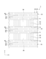
- FIG. FIG. 2 is a top view showing the vapor chamber according to the first embodiment.
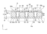
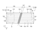
- 3 is a cross-sectional view taken along line AA of FIG. 2.
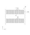
- FIG. 4 is a top view of the lower sheet of FIG. 3;
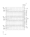
- FIG. 5 is a bottom view of the upper sheet of FIG. 3;
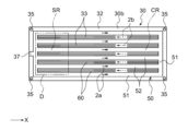
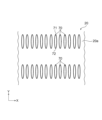
- FIG. 6 is a top view of the wick sheet of FIG. 3;
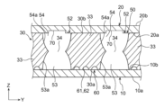
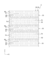
- FIG. 7 is a partially enlarged sectional view of FIG. 3.
- FIG. 8 is a top view of FIG. 7.
- FIG. 9 is a partially enlarged bottom view of FIG. 5 at a position corresponding to FIG. 8.
- FIG. 10 is a partially enlarged top view of the vapor chamber of FIG.
- FIG. 12 is a modified example of FIG.
- FIG. 13 is a modified example of FIG.
- FIG. 14 is a modified example of FIG.
- FIG. 15 is another modified example of FIG.
- FIG. 16 is another modified example of FIG.
- FIG. 17 is a modified example of FIG.
- FIG. 18 is another modified example of FIG.
- FIG. 19 is another modified example of FIG.
- FIG. 20 is another modified example of FIG.
- FIG. 21 is a partially enlarged top view showing the vapor chamber according to the second embodiment.
- FIG. 22 is a modified example of FIG. FIG.
- FIG. 23 is a partially enlarged top view showing the vapor chamber according to the third embodiment.
- FIG. 24 is a partially enlarged top view showing the vapor chamber according to the fourth embodiment.
- FIG. 25 is a partially enlarged top view showing the vapor chamber according to the fifth embodiment.
- FIG. 26 is a partially enlarged top view showing the vapor chamber according to the sixth embodiment.
- FIG. 27 is a partially enlarged top view showing the vapor chamber according to the seventh embodiment.
- FIG. 28 is a modified example of FIG.
- FIG. 29 is another modified example of FIG.
- FIG. 30 is a partially enlarged top view showing the vapor chamber according to the eighth embodiment.
- FIG. 31 is a modified example of FIG.
- FIG. 32 is a partially enlarged top view showing the vapor chamber according to the ninth embodiment.
- FIG. 33 is a modified example of FIG.
- FIG. 34 is another modified example of FIG.
- FIG. 35 is a partially enlarged sectional view showing the vapor chamber according to the tenth embodiment.
- FIG. 36 is a partially enlarged sectional view showing the vapor chamber according to the eleventh embodiment.
- FIG. 37 is a partially enlarged sectional view showing the vapor chamber according to the twelfth embodiment.
- FIG. 38 is a partially enlarged top view showing the vapor chamber according to the thirteenth embodiment.
- FIG. 39 is a top view showing the vapor chamber according to the fourteenth embodiment.
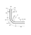
- 40 is a side view showing the vapor chamber bent along the bend line of FIG. 39;
- FIG. 41 is a modified example of FIG. FIG.
- FIG. 42 is a schematic diagram showing an example of the vapor chamber according to the fifteenth embodiment.
- FIG. 43 is a schematic diagram showing another example of the vapor chamber according to the fifteenth embodiment.
- FIG. 44 is an external perspective view showing the vapor chamber according to the fifteenth embodiment.
- 45 is a plan view of the vapor chamber shown in FIG. 42 before bending;
- FIG. 46 is a cross-sectional view taken along line AA-AA of FIG. 45.
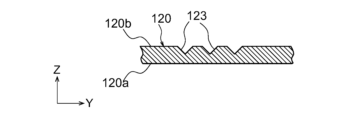
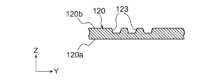
- FIG. 47 is a plan view showing the inner surface of the first sheet shown in FIG. 46.
- FIG. 48 is a plan view showing the inner surface of the second sheet shown in FIG. 46.
- FIG. 49 is a cross-sectional view taken along line BB-BB of FIG. 48.
- FIG. 50 is a partially enlarged plan view showing a modified example of the second seat outer surface concave portion shown in FIG. 45.
- FIG. FIG. 51 is a modified example of FIG.
- FIG. 52 is another modified example of FIG.
- FIG. 53 is another modified example of FIG.
- FIG. 54 is another modified example of FIG. 55 is a plan view showing the first main body surface of the wick sheet shown in FIG. 46.
- FIG. 56 is a plan view showing the second main body surface of the wick sheet shown in FIG. 46.
- FIG. 57 is a partially enlarged sectional view of FIG. 46.
- FIG. FIG. 58 is a partially enlarged view of the liquid flow path shown in FIG. 55.
- FIG. 59 is a schematic cross-sectional view showing the bend region of the vapor chamber shown in FIG.
- FIG. 60 is a partially enlarged plan view showing a modified example of the second seat outer surface concave portion shown in FIG. 45.
- FIG. FIG. 61 is a modified example of FIG.
- FIG. 62 is another modified example of FIG.
- FIG. 63 is another modified example of FIG. 64 is a schematic cross-sectional view showing one variation of the bending region of the vapor chamber shown in FIG. 59.
- FIG. 65 is a partially enlarged plan view showing a modification of the vapor chamber shown in FIG. 45.
- FIG. 66 is a cross-sectional view taken along line CC--CC of FIG. 65.
- FIG. 69 is a partially enlarged sectional view showing the vapor chamber according to the seventeenth embodiment.
- 70 is a partially enlarged plan view showing the second seat outer surface concave portion and the land concave portion shown in FIG. 69.
- the shapes of multiple parts that can be expected to have similar functions are regularly described, but the shapes are not limited to strict meanings and are expected to have the relevant functions.
- the shapes of the portions may differ from each other.
- the boundary lines indicating the joint surfaces of members are shown as simple straight lines for convenience, but they are not limited to strict straight lines, and desired joint performance can be expected.
- the shape of the boundary line is arbitrary as long as it is possible.
- FIG. A vapor chamber 1 according to the present embodiment is a device mounted on an electronic device E in order to cool a device D (device to be cooled) as a heating element housed in the electronic device E.
- FIG. Examples of the electronic device E include mobile terminals such as portable terminals and tablet terminals.
- Examples of the device D include electronic devices that generate heat, such as central processing units (CPUs), light emitting diodes (LEDs), and power semiconductors used in mobile terminals and the like.
- CPUs central processing units
- LEDs light emitting diodes
- power semiconductors used in mobile terminals and the like.
- the electronic device E on which the vapor chamber 1 according to the present embodiment is mounted will be described by taking a tablet terminal as an example.
- the electronic device E (tablet terminal) includes a housing H, a device D housed in the housing H, and a vapor chamber 1 .
- a touch panel display TD is provided on the front surface of the housing H.
- the vapor chamber 1 is housed within the housing H and arranged to be in thermal contact with the device D. As shown in FIG. This allows the vapor chamber 1 to receive the heat generated by the device D when the electronic equipment E is used.
- the heat received by the vapor chamber 1 is released to the outside of the vapor chamber 1 via working fluids 2a and 2b, which will be described later. In this way device D is effectively cooled. If the electronic device E is a tablet terminal, the device D corresponds to a central processing unit or the like.
- the vapor chamber 1 includes a sealed space 3 in which working fluids 2a, 2b are enclosed.
- the vapor chamber 1 is configured so that the working fluids 2a and 2b flow through the sealed space 3 while repeating phase changes, thereby cooling the device D of the electronic equipment E described above.
- working fluids 2a and 2b include pure water, ethanol, methanol, acetone, etc., and mixtures thereof.
- the vapor chamber 1 is interposed between a lower sheet 10 (second sheet), an upper sheet 20 (first sheet), and between the lower sheet 10 and the upper sheet 20. and a wick sheet 30 (main body sheet).
- vapor chamber 1 is composed of lower sheet 10 , upper sheet 20 and wick sheet 30 .
- lower sheet 10, wick sheet 30 and upper sheet 20 are laminated in this order.
- the wick sheet 30 is made up of one sheet is shown, but the wick sheet 30 may be made up of two or more sheets. The number of sheets of the sheet 30 is arbitrary.
- the vapor chamber 1 is generally formed in the shape of a thin flat plate.
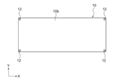
- the planar shape of the vapor chamber 1 is arbitrary, it may be rectangular as shown in FIG.
- the planar shape of the vapor chamber 1 may be, for example, a rectangle having one side of 10 mm or more and 200 mm or less and another side of 50 mm or more and 600 mm or less, or a square having one side of 40 mm or more and 300 mm or less.
- Planar dimensions are arbitrary.
- the planar shape of the vapor chamber 1 is a rectangular shape whose longitudinal direction is the X direction (first direction) and whose lateral direction is the Y direction (second direction) perpendicular to the X direction. An example will be described.
- the lower sheet 10, the upper sheet 20 and the wick sheet 30 may also have the same planar shape as the vapor chamber 1, as shown in FIGS.
- the planar shape of the vapor chamber 1 is not limited to a rectangular shape, and may be any shape such as a circular shape, an elliptical shape, an L-shape, a T-shape, and a U-shape.
- the vapor chamber 1 includes an evaporation area SR where the working fluid 2b evaporates and a condensation area CR where the working steam 2a condenses.
- the working vapor 2a is a working fluid in a gaseous state, that is, a vapor of the working fluid
- the working fluid 2b is a working fluid in a liquid state, that is, a liquid of the working fluid.
- the evaporation area SR is an area that overlaps with the device D in plan view, and is an area where the device D is attached.
- the evaporation area SR can be arranged at any position on the vapor chamber 1 .
- an evaporation region SR is formed on the negative side of the vapor chamber 1 in the X direction (left side in FIG. 2). Heat from the device D is transmitted to the evaporation region SR, and this heat causes the working liquid 2b to evaporate to generate the working vapor 2a.
- the heat from the device D can be transferred not only to the region overlapping the device D in plan view, but also to the periphery of the region. Therefore, the evaporation region SR includes a region that overlaps the device D and a peripheral region thereof in plan view.
- a plan view is a state in which the vapor chamber 1 is viewed from a direction orthogonal to the surface receiving heat from the device D and the surface emitting the received heat.
- the surface receiving heat corresponds to the upper sheet outer surface 20b of the upper sheet 20, which will be described later
- the surface emitting heat corresponds to the lower sheet outer surface 10a of the lower sheet 10, which will be described later.
- the surface receiving heat may correspond to the lower sheet outer surface 10a
- the surface emitting heat may correspond to the upper sheet outer surface 20b.
- a state of viewing the vapor chamber 1 from above or a state of viewing from below corresponds to a plan view.
- the condensation area CR is an area that does not overlap with the device D in plan view, and is an area where the working steam 2a mainly releases heat and condenses.
- the condensation area CR can also be said to be an area around the evaporation area SR.
- a condensation region CR is formed on the positive side of the vapor chamber 1 in the X direction (right side in FIG. 2). Heat from the working steam 2a is released to the lower sheet 10 in the condensation region CR, where the working steam 2a is cooled and condensed to produce a working fluid 2b.
- the vertical relationship may be disrupted depending on the orientation of the mobile terminal.
- the sheet that receives heat from the device D is referred to as the upper sheet 20 described above, and the sheet that releases the received heat is referred to as the lower sheet 10 described above. Therefore, the following description will be made with the lower sheet 10 arranged on the lower side and the upper sheet 20 arranged on the upper side.
- the lower sheet 10 has a lower sheet outer surface 10a (second sheet outer surface) provided on the side opposite to the wick sheet 30, and a lower sheet inner surface 10b (second sheet outer surface) facing the wick sheet 30. 2 seat inner surface) and .
- a housing member Ha which constitutes a part of a housing H of a mobile terminal or the like, is attached to the outer surface 10a of the lower seat.
- the entire lower seat outer surface 10a may be covered with the housing member Ha.
- the lower sheet 10 may be formed flat as a whole, and may have a uniform thickness as a whole.
- alignment holes 12 may be provided at the four corners of the lower sheet 10 .
- the planar shape of the alignment hole 12 is circular, but is not limited to this. Alignment holes 12 may pass through lower sheet 10 .
- the upper sheet 20 has an upper sheet inner surface 20a (first sheet inner surface) facing the wick sheet 30 and an upper sheet outer surface 20b (first sheet inner surface) provided opposite to the upper sheet inner surface 20a. outer surface) and The device D described above is attached to the upper sheet outer surface 20b. Further, as shown in FIGS. 3 and 5, the upper sheet 20 includes an upper sheet groove 70 (first sheet groove) provided in the inner surface 20a of the upper sheet. Details of the upper seat groove 70 will be described later.
- alignment holes 22 may be provided at the four corners of the upper sheet 20 .
- the planar shape of the alignment hole 22 is circular, but is not limited to this.
- Alignment holes 22 may extend through upper sheet 20 .
- the wick sheet 30 includes a wick sheet lower surface 30a (second main body surface) and a wick sheet upper surface 30b (first main body surface) provided on the opposite side of the wick sheet lower surface 30a. I'm in.
- the wick sheet lower surface 30 a faces the lower sheet inner surface 10 b of the lower sheet 10 .
- the wick sheet upper surface 30 b faces the upper sheet inner surface 20 a of the upper sheet 20 .
- the lower sheet inner surface 10b and the wick sheet lower surface 30a may be permanently joined to each other by thermocompression.
- the upper sheet inner surface 20a and the wick sheet upper surface 30b may be permanently joined together by thermocompression bonding. Diffusion bonding can be given as an example of bonding by thermocompression bonding.
- the lower sheet 10, the upper sheet 20 and the wick sheet 30 may be joined by other methods such as brazing instead of diffusion joining.
- the term "permanently joined” is not limited to a strict meaning, and means that the vapor chamber 1 is joined to such an extent that the sealing of the sealed space 3 can be maintained during operation of the vapor chamber 1. used as a term.
- the wick sheet 30 includes a frame portion 32 and a plurality of lands 33 provided within the frame portion 32 .
- the frame portion 32 and the land portion 33 are portions where the material of the wick sheet 30 remains without being etched in the etching process described later.
- the frame body portion 32 is formed in a rectangular frame shape in plan view.
- a steam channel portion 50 is provided inside the frame portion 32 .
- the steam channel portion 50 contains the working fluids 2a and 2b.
- Each land portion 33 is provided inside the frame portion 32 , and a steam flow path portion 50 is provided around each land portion 33 . Therefore, the working steam 2 a flows around each land portion 33 .
- each land portion 33 extends along the X direction (horizontal direction in FIG. 6) in plan view, and the planar shape of each land portion 33 is an elongated rectangular shape. Moreover, each land part 33 is located in a line along the Y direction (vertical direction in FIG. 6) orthogonal to the X direction. The land portions 33 may be arranged in the Y direction at regular intervals.
- the width w1 (see FIG. 7) of each land portion 33 may be, for example, 100 ⁇ m to 3000 ⁇ m.
- the width w1 of the land portion 33 is the dimension of the land portion 33 in the Y direction, and means the dimension in the Z direction at the position where the through portion 34, which will be described later, exists.
- the X direction is specified as the direction in which the second steam passage 52 of the steam passage portion 50, which will be described later, extends.
- the Y direction is specified as a direction orthogonal to the X direction in plan view.
- the Z direction is specified as a direction orthogonal to the X direction and the Y direction, and corresponds to the thickness direction of the wick sheet 30 .
- the frame portion 32 and each land portion 33 are diffusion-bonded to the lower sheet 10 and are diffusion-bonded to the upper sheet 20 . This improves the mechanical strength of the vapor chamber 1 .
- a wall surface 53 a of the lower steam flow channel recess 53 and a wall surface 54 a of the upper steam flow channel recess 54 which will be described later, form side walls of the land portion 33 .
- the wick sheet lower surface 30a and the wick sheet upper surface 30b may be formed flat across the frame portion 32 and each land portion 33. As shown in FIG.
- alignment holes 35 may be provided at the four corners of the wick sheet 30 .
- the planar shape of the alignment hole 35 is circular, but is not limited to this.
- the alignment holes 35 may pass through the wick sheet 30 .
- the wick sheet 30 includes a steam channel portion 50 through which the working steam 2a passes, and a liquid channel portion 60 that communicates with the steam channel portion 50 and through which the working fluid 2b passes.
- the steam channel portion 50 is mainly a channel through which the working steam 2a passes.
- the working fluid 2b may also pass through the vapor flow path portion 50 .
- the steam channel portion 50 may extend through the wick sheet 30 from the wick sheet lower surface 30 a to the wick sheet upper surface 30 b.
- the steam channel portion 50 may be covered with the lower sheet 10 on the wick sheet lower surface 30a, and may be covered with the upper sheet 20 on the wick sheet upper surface 30b.
- the steam flow path section 50 may include a first steam passage 51 and a plurality of second steam passages 52.
- the first steam passage 51 is formed between the frame portion 32 and the land portion 33 .
- the first steam passage 51 is formed continuously inside the frame portion 32 and outside the land portion 33 .
- the planar shape of the first steam passage 51 is a rectangular frame shape.
- the second steam passage 52 is formed between land portions 33 adjacent to each other.
- the second steam passage 52 extends along the X direction.
- the planar shape of the second steam passage 52 is an elongated rectangular shape.
- the plurality of lands 33 partition the steam flow path section 50 into a first steam passage 51 and a plurality of second steam passages 52 .
- the steam flow path portion 50 includes the first steam passage 51 in the present embodiment, the steam flow path portion 50 does not have to include the first steam passage 51 . That is, the frame portion 32 and the land portion 33 may be arranged adjacent to each other, and no steam passage may be provided between the frame portion 32 and the land portion 33 .
- the first steam passage 51 and the second steam passage 52 may extend through the wick sheet 30 from the wick sheet lower surface 30a to the wick sheet upper surface 30b.
- the first steam passage 51 and the second steam passage 52 include a lower steam passage recess 53 provided in the wick sheet lower surface 30a and an upper steam passage recess 54 provided in the wick sheet upper surface 30b.
- the lower steam channel recess 53 and the upper steam channel recess 54 communicate with each other, and the first steam channel 51 and the second steam channel 52 are formed to extend from the wick sheet lower surface 30a to the wick sheet upper surface 30b. .
- the lower steam flow path concave portion 53 is formed in a concave shape on the wick sheet lower surface 30a by etching the wick sheet 30 from the wick sheet lower surface 30a in an etching process to be described later.
- forming a concave shape on the lower surface 30a of the wick sheet means that it is formed so as to be concave from the lower surface 30a of the wick sheet.
- the lower steam channel recess 53 has a curved wall surface 53a, as shown in FIG.
- This wall surface 53a defines the lower steam flow channel recessed portion 53, and in the cross section shown in FIG. 7, is curved so as to approach the opposing wall surface 53a as it proceeds toward the wick sheet upper surface 30b.
- the hydraulic fluid 2b can adhere to this wall surface 53a.
- Such a lower steam passage concave portion 53 constitutes part (lower half) of the first steam passage 51 and part (lower half) of the second steam passage 52 .
- the upper steam flow path concave portion 54 is formed in a concave shape on the wick sheet upper surface 30b by etching the wick sheet 30 from the wick sheet upper surface 30b in an etching process to be described later.
- being formed in a concave shape on the upper surface 30b of the wick sheet means forming so as to be concave from the upper surface 30b of the wick sheet.
- the upper steam passage recess 54 has a curved wall surface 54a, as shown in FIG.
- the wall surface 54a defines the upper steam flow channel recessed portion 54, and in the cross section shown in FIG. 7, the wall surface 54a curves toward the opposing wall surface 54a as it proceeds toward the wick sheet lower surface 30a.
- the hydraulic fluid 2b can adhere to this wall surface 54a.
- Such an upper steam passage concave portion 54 constitutes part (upper half) of the first steam passage 51 and part (upper half) of the second steam passage 52 .
- the wall surface 53a of the lower steam flow path recessed portion 53 and the wall surface 54a of the upper steam flow path recessed portion 54 are connected to form the through portion 34.
- the planar shape of the penetration portion 34 in the first steam passage 51 is a rectangular frame like the first steam passage 51
- the planar shape of the penetration portion 34 in the second steam passage 52 is , and has an elongated rectangular shape like the second steam passage 52 .
- the penetrating portion 34 may be defined by a ridgeline formed so that the wall surface 53a of the lower steam flow channel recessed portion 53 and the wall surface 54a of the upper steam flow channel recessed portion 54 merge and protrude inward.
- the plane area of the first steam passage 51 may be the smallest, and the plane area of the second steam passage 52 may be the smallest.
- the width w2 (see FIG. 7) of the penetration portion 34 of each steam passage 51, 52 may be, for example, 400 ⁇ m to 1600 ⁇ m.
- the width w2 of the through portion 34 of the first steam passage 51 corresponds to the gap between the land portions 33 adjacent to each other in the Y direction.
- the width w2 of the through portion 34 of the second steam passage 52 corresponds to the gap between the frame portion 32 and the land portion 33 in the Y direction (or the X direction).
- the position of the penetrating portion 34 in the Z direction may be an intermediate position between the wick sheet lower surface 30a and the wick sheet upper surface 30b.
- the position is not limited to this, and may be a position closer to the lower seat 10 than the intermediate position, or a position closer to the upper seat 20 than the intermediate position.
- the position of the penetrating portion 34 in the Z direction is arbitrary.
- the cross-sectional shapes of the first steam passage 51 and the second steam passage 52 include the penetrating portion 34 defined by the ridgeline formed to protrude inward.
- the cross-sectional shape of the first steam passage 51 and the cross-sectional shape of the second steam passage 52 may be trapezoidal, rectangular, or barrel-shaped.
- the steam passage portion 50 including the first steam passage 51 and the second steam passage 52 configured in this manner constitutes part of the sealed space 3 described above.
- the first steam passage 51 and the second steam passage 52 are formed mainly by the lower sheet 10, the upper sheet 20, and the frame portion 32 and land portion 33 of the wick sheet 30 described above. defined.
- Each of the steam passages 51, 52 has a relatively large cross-sectional area for passage of the working steam 2a.
- FIG. 3 shows the first steam passage 51, the second steam passage 52, etc. in an enlarged manner for clarity of the drawing, and the number and arrangement of these steam passages 51, 52, etc. are not shown in the figure. 2. It is different from FIGS. 6 to 10 and the like.
- a plurality of support portions that support the land portion 33 to the frame portion 32 may be provided in the steam flow path portion 50 .
- a plurality of connecting portions 38 may be provided to connect the land portions 33 adjacent to each other.
- the support portion and the connecting portion 38 may be formed so as not to block the flow of the working steam 2a that diffuses through the steam flow path portion 50 .
- the wick sheet 30 may be arranged at a position close to one of the wick sheet lower surface 30a and the wick sheet upper surface 30b and at a position close to the other, a space forming a recessed portion of the steam flow path may be formed.
- the thickness of the supporting portion and the connecting portion 38 can be made thinner than the thickness of the wick sheet 30, and the first steam passage 51 and the second steam passage 52 are separated in the X direction and the Y direction. can be prevented.
- the liquid channel portion 60 is mainly a channel through which the working liquid 2b passes.
- the working steam 2 a may also pass through the liquid flow path portion 60 .
- the liquid flow path portion 60 may be provided on the wick sheet upper surface 30b of the wick sheet 30.
- the liquid flow path portion 60 is provided on the wick sheet upper surface 30 b of each land portion 33 .
- the liquid channel portion 60 constitutes a part of the above-described sealed space 3 and communicates with the vapor channel portion 50 .
- the liquid flow path portion 60 is configured as a capillary structure (wick) for transporting the working liquid 2b to the evaporation region SR.
- the liquid flow path portion 60 may be formed over the entire wick sheet upper surface 30 b in each land portion 33 .
- the liquid flow path portion 60 may be provided on the wick sheet upper surface 30 b of the frame portion 32 .
- the liquid flow path section 60 may be composed of a plurality of grooves provided on the wick sheet upper surface 30b. More specifically, the liquid flow path portion 60 includes a plurality of main liquid flow path grooves 61 through which the working fluid 2b passes, and a plurality of liquid flow path communication grooves 65 communicating with the main liquid flow path grooves 61. may be present.
- Each liquid flow channel main groove 61 extends along the X direction, as shown in FIG.
- the main liquid channel groove 61 has a small channel cross-sectional area mainly so that the working fluid 2b flows by capillary action.
- the channel cross-sectional area of the liquid channel main groove 61 is smaller than the channel cross-sectional areas of the steam passages 51 and 52 .
- the liquid flow path main groove 61 is configured to transport the working fluid 2b condensed from the working steam 2a to the evaporation region SR.
- the main liquid flow channel grooves 61 may be arranged along the Y direction.
- the main liquid flow channel grooves 61 may be arranged in parallel with each other at regular intervals.
- the liquid flow channel main groove 61 may be formed by etching the wick sheet 30 from the wick sheet upper surface 30b in an etching process to be described later. Accordingly, the main liquid flow channel groove 61 may have a curved wall surface 62 as shown in FIG. The wall surface 62 defines the main liquid flow channel groove 61 and may be concavely curved toward the lower surface 30a of the wick sheet.
- the width w3 of the main groove 61 of the liquid flow path may be, for example, 5 ⁇ m to 150 ⁇ m.
- the width w3 of the main liquid flow channel groove 61 means the dimension on the wick sheet upper surface 30b.
- the depth h1 (dimension in the Z direction) of the main liquid flow channel groove 61 shown in FIG. 7 may be, for example, 3 ⁇ m to 150 ⁇ m.
- each liquid channel communication groove 65 extends along the direction crossing the X direction.
- each liquid channel connecting groove 65 extends along the Y direction and is formed perpendicular to the main liquid channel groove 61 .
- Some liquid flow channel communication grooves 65 communicate with adjacent liquid flow channel main grooves 61 .
- the other liquid channel communication groove 65 communicates the first steam passage 51 or the second steam passage 52 with the liquid channel main groove 61 . That is, the liquid flow channel connecting groove 65 extends from the edge of the land portion 33 in the Y direction to the main liquid flow channel groove 61 adjacent to the edge. In this manner, the first steam passage 51 and the liquid flow path main groove 61 communicate with each other, and the second steam path 52 and the liquid flow path main groove 61 communicate with each other.
- the liquid channel communication groove 65 has a small channel cross-sectional area mainly so that the working fluid 2b flows by capillary action.
- the channel cross-sectional area of the liquid channel communication groove 65 is smaller than the channel cross-sectional areas of the steam passages 51 and 52 .
- Each liquid channel communication groove 65 may be arranged along the X direction.
- the liquid flow channel communication grooves 65 may be arranged in parallel with each other at regular intervals.
- the liquid channel communication groove 65 may also be formed by etching, similar to the liquid channel main groove 61 .
- the liquid flow path connecting groove 65 may have a curved wall surface (not shown) similar to that of the liquid flow path main groove 61 .
- the width w4 of the liquid channel communication groove 65 may be equal to the width w3 of the liquid channel main groove 61 .
- the width w4 of the liquid flow communication groove 65 may be larger or smaller than the width w3 of the liquid flow main groove 61, without being limited to this.
- the depth of the liquid channel communication groove 65 may be equal to the depth h1 of the liquid channel main groove 61 . However, it is not limited to this, and the depth of the liquid flow channel connecting groove 65 may be deeper or shallower than the depth h1 of the main liquid flow channel groove 61 .
- the liquid flow path portion 60 may have a liquid flow path projection row 63 provided on the wick sheet upper surface 30b.
- the liquid flow path protrusion row 63 is provided between the liquid flow path main grooves 61 adjacent to each other.
- Each liquid flow path projection row 63 includes a plurality of liquid flow path projections 64 arranged in the X direction.
- the liquid flow path convex portion 64 is in contact with the upper sheet inner surface 20a.
- Each liquid flow path convex portion 64 is formed in a rectangular shape in a plan view so that the X direction is the longitudinal direction.
- the main liquid flow channel groove 61 is interposed between the liquid flow channel protrusions 64 adjacent to each other in the Y direction.
- a liquid flow path connecting groove 65 is interposed between the liquid flow path protrusions 64 adjacent to each other in the X direction.
- the liquid flow path convex portion 64 is a portion where the material of the wick sheet 30 remains without being etched in the etching process described later. As shown in FIG. 8, the planar shape of the liquid flow path convex portion 64 (the shape at the position of the wick sheet upper surface 30b) may be rectangular.
- the liquid flow path protrusions 64 may be arranged in a zigzag pattern. More specifically, the liquid flow path projections 64 of the liquid flow path projection arrays 63 that are adjacent to each other in the Y direction may be displaced from each other in the X direction. This shift amount may be half the arrangement pitch of the liquid flow path protrusions 64 in the X direction.
- the width w5 (dimension in the Y direction) of the liquid flow path convex portion 64 shown in FIG. 8 may be, for example, 5 ⁇ m to 500 ⁇ m.
- the width w5 of the liquid flow path convex portion 64 means the dimension on the upper surface 30b of the wick sheet.
- the width w5 of the liquid flow path convex portion 64 corresponds to the gap between the liquid flow path main grooves 61 adjacent to each other in the Y direction.
- the arrangement of the liquid flow path protrusions 64 is not limited to the zigzag pattern, and may be arranged in parallel. In this case, the liquid flow path projections 64 of the liquid flow path projection rows 63 adjacent to each other in the Y direction are also aligned in the X direction.
- the vapor chamber 1 may include an injection part 4 for injecting the working fluid 2b into the sealed space 3.
- the position of the injection part 4 is arbitrary, but as shown in FIG. 2, the injection part 4 may be provided at the edge of the vapor chamber 1 on the negative side in the X direction (left side in FIG. 2).
- the injection part 4 may have an injection channel 37 formed in the wick sheet 30 . After the working liquid 2b is injected, the injection channel 37 may be sealed.
- the materials forming the lower sheet 10, the upper sheet 20 and the wick sheet 30 are not particularly limited as long as they have good thermal conductivity.
- Lower sheet 10, upper sheet 20 and wick sheet 30 may comprise, for example, copper or a copper alloy.
- the thermal conductivity of each sheet 10, 20, 30 can be enhanced, and the heat radiation efficiency of the vapor chamber 1 can be enhanced.
- corrosion can be prevented.
- Other metal materials such as aluminum and titanium, or other metal alloy materials such as stainless steel may be used for these sheets 10, 20, and 30 as long as desired heat radiation efficiency can be obtained and corrosion can be prevented. good.
- the thickness t1 of the vapor chamber 1 shown in FIG. 3 may be, for example, 100 ⁇ m to 1000 ⁇ m.
- the thickness t1 of the vapor chamber 1 may be, for example, 100 ⁇ m to 1000 ⁇ m.
- the vapor flow path portion 50 can be properly secured, and the vapor chamber 1 can function properly.
- the thickness t1 to 1000 ⁇ m or less, thickening of the vapor chamber 1 can be suppressed.
- the thickness t2 of the lower sheet 10 shown in FIG. 3 may be, for example, 6 ⁇ m to 100 ⁇ m. By setting the thickness t2 of the lower sheet 10 to 6 ⁇ m or more, the mechanical strength of the lower sheet 10 can be ensured. On the other hand, by setting the thickness t2 of the lower sheet 10 to 100 ⁇ m or less, thickening of the vapor chamber 1 can be suppressed.
- the thickness t3 of the upper sheet 20 shown in FIG. 3 may be set similarly to the thickness t2 of the lower sheet 10. The thickness t3 of the upper sheet 20 and the thickness t2 of the lower sheet 10 may differ from each other.
- the thickness t4 of the wick sheet 30 shown in FIG. 3 may be, for example, 50 ⁇ m to 400 ⁇ m.
- the thickness t4 of the wick sheet 30 shown in FIG. 3 may be, for example, 50 ⁇ m to 400 ⁇ m.
- the upper sheet 20 of the vapor chamber 1 includes the upper sheet grooves 70 provided in the upper sheet inner surface 20a.
- the upper sheet 20 may include a plurality of upper sheet grooves 70, as shown in FIGS.
- FIG. 10 is a partially enlarged top view showing a state in which the wick sheet 30 and the upper sheet 20 are overlapped.
- the upper seat groove 70 is provided at a position overlapping the steam passages 51 and 52 in plan view.
- the upper seat groove 70 is provided at a position overlapping the second steam passage 52 in plan view, and the entire upper seat groove 70 overlaps the second steam passage 52 in plan view.
- the upper seat groove 70 is provided between the land portions 33 adjacent to each other in plan view.
- the upper seat groove 70 may be provided at a position overlapping the first steam passage 51 in plan view. In this case, the upper seat groove 70 may be provided at a position overlapping a portion of the first steam passage 51 extending in the X direction in plan view.
- the upper seat groove 70 extends along the direction crossing the X direction.
- the upper seat groove 70 extends along the Y direction orthogonal to the X direction.
- the planar shape of the upper seat groove 70 is an elongated rectangular shape.
- the upper sheet groove 70 includes a first end portion 71 and a second end portion 72 provided at both ends in the Y direction.
- the first end portion 71 constitutes the end portion of the upper sheet groove 70 on the positive side in the Y direction (upper side in FIGS. 9 and 10)
- the second end portion 72 constitutes the end portion of the upper sheet groove 70 on the negative side in the Y direction. (lower side in FIGS. 9 and 10).
- both the first end portion 71 and the second end portion 72 are provided at positions overlapping the second steam passage 52 in plan view.
- the upper seat grooves 70 may be arranged along the X direction.
- the upper sheet grooves 70 may be arranged in parallel with each other at regular intervals.
- the upper sheet groove 70 may be formed by etching the upper sheet 20 from the upper sheet inner surface 20a. Accordingly, the upper sheet groove 70 may have a curved wall surface 73 as shown in FIG. 11 . This wall surface 73 defines the upper seat groove 70 and may curve concavely from the upper seat inner surface 20a toward the upper seat outer surface 20b. In the example shown in FIG. 11, the cross-sectional shape of the upper seat groove 70 is semicircular.
- the upper seat groove 70 mainly has a small flow passage cross-sectional area so that the hydraulic fluid 2b flows by capillary action.
- the upper seat groove 70 is a groove having a channel cross-sectional area smaller than the channel cross-sectional areas of the steam passages 51 and 52 .
- the upper seat groove 70 facilitates the movement of the hydraulic fluid 2b between the steam passages 51, 52 and the liquid flow path portion 60.
- the channel cross-sectional area of the upper sheet groove 70 may be equal to the channel cross-sectional area of the liquid channel main groove 61 .
- the flow path cross-sectional area of the upper sheet groove 70 may be smaller than the flow path cross-sectional area of the liquid flow main groove 61 without being limited to this.
- the capillary action of the upper seat groove 70 imparts a driving force to the hydraulic fluid 2b from the liquid flow path portion 60 toward the upper seat groove 70, and the hydraulic fluid 2b in the liquid flow path portion 60 passes through the upper seat groove 70. can be quickly moved to the steam passages 51 and 52.
- the flow channel cross-sectional area of the upper sheet groove 70 may be larger than the flow channel cross-sectional area of the main liquid flow channel groove 61 .
- the capillary action of the upper seat groove 70 gives the working fluid 2b a driving force from the upper seat groove 70 toward the liquid flow path portion 60, causing the working fluid 2b in the steam passages 51 and 52 to pass through the upper seat groove 70. can be quickly moved to the liquid flow path section 60.
- the length L1 (dimension in the Y direction) of the upper sheet groove 70 shown in FIG. (see FIG. 8). If the upper seat groove 70 has a channel cross-sectional area smaller than the channel cross-sectional areas of the steam passages 51 and 52, the length L1 of the upper seat groove 70 is larger than the width w6 of the upper seat groove 70, which will be described later. It can be big.
- the length L1 of the upper sheet groove 70 may be, for example, greater than 5 ⁇ m.
- the width w6 (dimension in the X direction) of the upper sheet groove 70 shown in FIGS. 9 and 11 may be equal to the width w3 (see FIG. 7) of the main liquid flow path groove 61. However, it is not limited to this, and the width w6 of the upper sheet groove 70 may be smaller or larger than the width w3 of the main liquid flow channel groove 61 .
- the width w6 (dimension in the X direction) of the upper sheet groove 70 may be, for example, 5 ⁇ m to 150 ⁇ m.
- the width w6 of the upper sheet groove 70 means the dimension of the upper sheet inner surface 20a.
- the depth h2 (dimension in the Z direction) of the upper sheet groove 70 shown in FIG. 11 may be equal to the depth h1 of the main liquid flow channel groove 61 (see FIG. 7). However, it is not limited to this, and the depth h2 of the upper sheet groove 70 may be deeper or shallower than the depth h1 of the main liquid flow channel groove 61 .
- the depth h2 of the upper sheet groove 70 may be, for example, 3 ⁇ m to 150 ⁇ m.
- the present invention is not limited to this, and the gap w7 between the upper sheet grooves 70 adjacent to each other in the X direction may be larger than the width w5 of the liquid flow path convex portion 64.
- a gap w7 between upper sheet grooves 70 adjacent to each other in the X direction may be, for example, 3 ⁇ m to 500 ⁇ m.
- the planar shape of the upper seat groove 70 is an elongated rectangular shape, and the cross-sectional shape of the upper seat groove 70 is a semicircular shape, but it is not limited to this. , the shape of the upper seat groove 70 is arbitrary.
- the upper seat groove 70 is provided over the entire region overlapping the second steam passage 52 in a plan view, but the present invention is not limited to this, and the upper seat groove 70 is provided in a plane. It may be provided only in a part of the regions visually overlapping with the steam passages 51 and 52 .
- the upper sheet groove 70 may be arranged only in the evaporation region SR. Further, for example, the upper seat groove 70 may be arranged only in the condensation region CR.
- each sheet 10, 20, 30 is prepared.
- the sheet preparation process includes a lower sheet preparation process for preparing the lower sheet 10 , an upper sheet preparation process for preparing the upper sheet 20 , and a wick sheet preparation process for preparing the wick sheet 30 .
- a lower sheet base material having a desired thickness is prepared.
- the lower sheet base material may be a rolled material.
- the lower sheet base material is etched to form the lower sheet 10 having a desired planar shape.
- the lower sheet 10 having a desired planar shape may be formed by pressing the lower sheet base material. In this way, the lower sheet 10 as shown in FIG. 4 can be prepared.
- an upper sheet base material having a desired thickness is prepared.
- the upper sheet base material may be a rolled material.
- the upper sheet base material is etched to form the upper sheet 20 having a desired planar shape. This etching forms the above-described upper sheet groove 70 in the upper sheet 20 .
- the upper sheet 20 having a desired planar shape may be formed by pressing the upper sheet base material.
- the upper sheet grooves 70 may be formed by cutting the upper sheet base material. In this way, the upper sheet 20 as shown in FIG. 5 can be prepared.
- the wick sheet preparation process may include a material sheet preparation process of preparing a metal material sheet and an etching process of etching the metal material sheet.
- a material sheet preparation process of preparing a metal material sheet and an etching process of etching the metal material sheet.
- a flat metal material sheet having a desired thickness is prepared.
- the sheet of metal material may be a rolled material.
- the metal material sheet is etched from the first material surface and the second material surface to form the wick sheet 30 having a desired planar shape and the vapor channel portion 50 and the liquid channel portion 60.
- the wick sheet 30 as shown in FIG. 6 can be prepared.
- the first material surface and the second material surface of the metal material sheet may be etched simultaneously.
- the etching of the first material surface and the second material surface may be performed as separate steps.
- the vapor channel portion 50 and the liquid channel portion 60 may be formed by etching at the same time, but may be formed by etching in separate steps.
- an iron chloride-based etchant such as an aqueous ferric chloride solution or a copper chloride-based etchant such as an aqueous copper chloride solution may be used.
- the lower sheet 10, the upper sheet 20 and the wick sheet 30 are joined as a joining process.
- the lower sheet 10, the wick sheet 30 and the upper sheet 20 are laminated in this order.
- the sheets 10 , 20 and 30 may be aligned using the alignment hole 12 of the lower sheet 10 , the alignment hole 35 of the wick sheet 30 and the alignment hole 22 of the upper sheet 20 .
- the lower sheet 10, the wick sheet 30 and the upper sheet 20 are temporarily fixed.
- each sheet 10, 20, 30 may be tacked together by spot welding or laser welding.
- the lower sheet 10, the wick sheet 30 and the upper sheet 20 are then permanently joined together by thermocompression bonding.
- each sheet 10, 20, 30 may be bonded by diffusion bonding.
- the working fluid 2b is injected into the sealed space 3 from the injection channel 37 of the injection part 4 as an injection process.
- the injection channel 37 is sealed as a sealing process.
- communication between the sealed space 3 and the outside is cut off, and the sealed space 3 is sealed. Therefore, it is possible to obtain the sealed space 3 in which the hydraulic fluid 2b is enclosed, and to prevent the hydraulic fluid 2b in the sealed space 3 from leaking to the outside.
- the vapor chamber 1 according to this embodiment can be obtained.
- the vapor chamber 1 obtained as described above is installed in a housing H of a mobile terminal or the like.
- a device D such as a CPU, which is a device to be cooled, is attached to the upper sheet outer surface 20b of the upper sheet 20 (or the vapor chamber 1 is attached to the device D).
- the working fluid 2b in the sealed space 3 moves against the wall surfaces of the sealed space 3, that is, the wall surface 53a of the lower steam flow channel recess 53, the wall surface 54a of the upper steam flow channel recess 54, and the liquid flow channel portion 60 due to its surface tension. It adheres to the wall surface 62 of the liquid channel main groove 61 and the wall surface of the liquid channel connecting groove 65 .
- the hydraulic fluid 2b may also adhere to the portion of the lower seat inner surface 10b of the lower seat 10 exposed to the lower steam flow channel recessed portion 53 . Furthermore, the working fluid 2b may also adhere to the portions of the upper sheet inner surface 20a of the upper sheet 20 exposed to the upper vapor channel recess 54, the liquid channel main groove 61, and the liquid channel connecting groove 65. As shown in FIG.
- the working fluid 2b existing in the evaporation region SR receives heat from the device D.
- the received heat is absorbed as latent heat, and the working fluid 2b evaporates (vaporizes) to generate the working steam 2a.
- the generated working steam 2 a diffuses within the first steam passage 51 and the second steam passage 52 that form the sealed space 3 . More specifically, the working steam 2a mainly diffuses in the X direction in the portion of the first steam passage 51 extending in the X direction and the second steam passage 52 (see the solid line arrow in FIG. 6).
- the working steam 2a in each of the steam passages 51, 52 leaves the evaporation area SR and is transported to the relatively low-temperature condensation area CR (the right part in FIG. 6).
- the working steam 2a is mainly radiated to the lower sheet 10 and cooled.
- the heat received by the lower seat 10 from the working steam 2a is transferred to the outside air via the housing member Ha (see FIG. 3).
- the working steam 2a loses latent heat absorbed in the evaporation area SR by radiating heat to the lower sheet 10 in the condensation area CR. Thereby, the working steam 2a is condensed and the working liquid 2b is produced.
- the generated hydraulic fluid 2b adheres to the wall surfaces 53a and 54a of the respective vapor passage recesses 53 and 54, the lower sheet inner surface 10b of the lower sheet 10, and the upper sheet inner surface 20a of the upper sheet 20. As shown in FIG. Here, the working fluid 2b continues to evaporate in the evaporation region SR.
- the working fluid 2b existing in the area other than the evaporation area SR (that is, the condensation area CR) of the liquid flow path portion 60 is transported toward the evaporation area SR by the capillary action of each liquid flow path main groove 61. (see dashed arrow in FIG. 6).
- the working fluid 2b adhering to the wall surfaces 53a, 54a, the lower seat inner surface 10b, and the upper seat inner surface 20a moves to the liquid flow path portion 60, passes through the liquid flow path communication groove 65, and flows into the liquid flow path. It enters the mainstream groove 61 .
- each liquid flow path main groove 61 and each liquid flow path communication groove 65 are filled with the working fluid 2b.
- the filled working fluid 2b obtains a driving force toward the evaporation area SR due to the capillary action of each fluid flow channel main groove 61, and is smoothly transported toward the evaporation area SR.
- each liquid channel main groove 61 communicates with another adjacent liquid channel main groove 61 via the corresponding liquid channel communication groove 65 .
- the working fluid 2b is prevented from flowing between the main liquid flow channel grooves 61 adjacent to each other, and the occurrence of dryout in the main liquid flow channel grooves 61 is suppressed. Therefore, a capillary action is imparted to the working fluid 2b in each liquid flow path main groove 61, and the working fluid 2b is smoothly transported toward the evaporation region SR.
- the working fluid 2b that has reached the evaporation region SR receives heat from the device D again and evaporates.
- the working steam 2a evaporated from the working liquid 2b passes through the liquid flow channel communication groove 65 in the evaporation region SR and moves to the lower steam flow channel concave portion 53 and the upper steam flow channel concave portion 54 having a large flow channel cross-sectional area.
- the working steam 2a then diffuses within the respective steam flow channel recesses 53 and 54 .
- the working fluids 2a and 2b circulate within the sealed space 3 while repeating phase changes, that is, evaporation and condensation. This causes the heat of device D to be diffused and released. As a result, device D is cooled.
- upper sheet grooves 70 are provided in the upper sheet inner surface 20a of the upper sheet 20 .
- the upper seat groove 70 is provided at a position overlapping the steam passages 51 and 52 in plan view, and extends along a direction crossing the X direction.
- the working fluid 2b can smoothly move from the steam passages 51 and 52 to the liquid flow path portion 60 through the upper sheet groove 70, and smoothly flow into the main flow groove 61 of the liquid flow path. can enter.
- the working fluid 2b in the evaporation region SR, can move from the liquid flow path portion 60 to the vapor passages 51 and 52 through the upper sheet groove 70 . Therefore, the heat of the device D can be effectively absorbed by the working fluid 2b that has moved to the steam passages 51 and 52, and the device D can be cooled effectively.
- the upper seat 20 has the upper seat grooves 70 provided in the inner surface 20a of the upper seat, and is provided at a position overlapping the steam passages 51 and 52 in plan view. It includes an upper seat groove 70 extending along the transverse direction.
- the channel cross-sectional area of the upper sheet groove 70 may be smaller than the channel cross-sectional area of the main liquid channel groove 61 .
- the capillary action of the upper seat groove 70 imparts a driving force to the hydraulic fluid 2b from the liquid flow path portion 60 toward the upper seat groove 70, causing the hydraulic fluid 2b in the liquid flow path portion 60 to flow through the upper seat groove 70.
- the circulation of the working fluids 2a and 2b within the vapor chamber 1 can be further promoted.
- the channel cross-sectional area of the upper sheet groove 70 may be larger than the channel cross-sectional area of the main liquid channel groove 61 .
- the capillary action of the upper seat grooves 70 imparts a driving force to the hydraulic fluid 2b from the upper seat grooves 70 toward the liquid flow path portion 60, causing the hydraulic fluid 2b in the steam passages 51 and 52 to flow through the upper seat grooves 70. It can be quickly moved to the liquid flow path section 60 through the liquid flow path section 60 . Therefore, when such upper seat grooves 70 are arranged in the condensation area CR, the movement of the working fluid 2b from the steam passages 51 and 52 to the liquid flow path portion 60 can be effectively promoted in the condensation area CR. . As a result, the circulation of the working fluids 2a and 2b within the vapor chamber 1 can be further promoted.
- the liquid flow path portion 60 is provided on the wick sheet upper surface 30b.
- the upper sheet grooves 70 are provided in the upper sheet inner surface 20a facing the wick sheet upper surface 30b.
- the hydraulic fluid 2b that has flowed through the upper seat groove 70 can smoothly move to the vapor passages 51 and 52 or the liquid flow path portion 60.
- the circulation of the working fluids 2a and 2b within the vapor chamber 1 can be further promoted.
- liquid flow path portion 60 is provided on the upper surface 30b of the wick sheet.
- the present invention is not limited to this, and as shown in FIG. 12, the liquid flow path section 60 may be provided on the wick sheet lower surface 30a.
- the hydraulic fluid 2b flows from the liquid flow path portion 60 along the wall surface 53a of the lower steam flow path recessed portion 53 and the wall surface 54a of the upper steam flow path recessed portion 54, and flows through the upper seat groove 70. It can move to steam passages 51 , 52 .
- the working fluid 2b flows from the steam passages 51 and 52 through the upper seat groove 70, along the wall surface 53a of the lower steam channel recess 53 and the wall surface 54a of the upper steam channel recess 54, and into the liquid channel portion 60. can move. Therefore, the circulation of the working fluids 2a and 2b within the vapor chamber 1 can be promoted.
- the upper seat groove 70 is located at a position corresponding to the liquid flow channel communication groove 65 located closest to the steam passages 51 and 52 in the liquid flow channel portion 60. may be placed in That is, as shown in FIG. 13, the upper sheet groove 70 is located at the same position as the liquid flow passage communication groove 65 located closest to the vapor passages 51 and 52 in the liquid flow passage portion 60 in the X direction, and is the second in the Y direction.
- the first end portion 71 or the second end portion 72 may be arranged so as to face the liquid channel communication groove 65 .
- the upper seat groove 70 does not have to be arranged at any position other than this position in the X direction.
- planar shape of the upper seat groove 70 is an elongated rectangular shape (see FIG. 9).
- the present invention is not limited to this, and for example, as shown in FIG. 72) may have a rounded elongated shape.
- the planar shape of the upper seat groove 70 may be an elongated elliptical shape extending in the Y direction.
- the planar shape of the upper seat groove 70 may be a beaded shape in which a plurality of circles are partially overlapped and connected in the Y direction.
- the planar shape of the upper sheet groove 70 is arbitrary.
- the cross-sectional shape of the upper seat groove 70 is semicircular (see FIG. 11).
- the cross-sectional shape of the upper seat groove 70 may be triangular.
- the cross-sectional shape of the upper seat groove 70 may be rectangular.
- the cross-sectional shape of the upper seat groove 70 may be trapezoidal.
- the cross-sectional shape of the upper seat groove 70 may be a partially circular shape having a width wider than the opening on the inner side.
- the cross-sectional shape of the upper seat groove 70 is arbitrary as long as it has a channel cross-sectional area smaller than the channel cross-sectional areas of the steam passages 51 and 52 .
- FIG. 21 (Second embodiment) Next, a vapor chamber and electronic equipment according to a second embodiment of the present disclosure will be described with reference to FIGS. 21 and 22.
- FIG. 21 (Second embodiment) Next, a vapor chamber and electronic equipment according to a second embodiment of the present disclosure will be described with reference to FIGS. 21 and 22.
- FIG. 21 (Second embodiment) Next, a vapor chamber and electronic equipment according to a second embodiment of the present disclosure will be described with reference to FIGS. 21 and 22.
- the first sheet groove is provided over a position overlapping with the liquid flow path portion in a plan view, and the vapor
- the main difference is that it is provided so as to traverse the passage, and other configurations are substantially the same as those of the first embodiment shown in FIGS. 21 and 22, the same parts as in the first embodiment shown in FIGS. 1 to 20 are denoted by the same reference numerals, and detailed description thereof will be omitted.
- the upper seat groove 70 is provided over a position overlapping the liquid flow path portion 60 in plan view. That is, the upper seat groove 70 also overlaps the land portion 33 in plan view. As shown in FIG. 21, the upper sheet groove 70 may overlap the main liquid flow path groove 61 in plan view.
- the upper seat groove 70 is provided so as to traverse the steam passages 51 and 52 in the direction intersecting the X direction.
- the upper seat groove 70 is provided so as to cross the second steam passage 52 in the Y direction.
- a first end portion 71 and a second end portion 72 of the upper seat groove 70 are provided at positions overlapping the land portion 33 in plan view. More specifically, the first end portion 71 is provided at a position overlapping the one land portion 33 in plan view, and the second end portion 72 is adjacent to the one land portion 33 in plan view. is provided at a position overlapping the land portion 33 of the .
- the upper sheet groove 70 is provided over a position overlapping the liquid flow path portion 60 in plan view.
- the movement of the working fluid 2b between the steam passages 51, 52 and the liquid flow path portion 60 can be effectively promoted. Therefore, when such upper sheet grooves 70 are arranged in the evaporation region SR, it is possible to effectively promote the movement of the working fluid 2b from the liquid flow path portion 60 to the vapor passages 51 and 52 in the evaporation region SR. .
- the working steam 2a evaporated from the working fluid 2b in the liquid flow path portion 60 can be quickly moved to the steam passages 51 and 52 through the upper seat groove 70, and the evaporation region
- the movement of the working steam 2a in the SR from the liquid flow path portion 60 to the steam passages 51 and 52 can be effectively promoted.
- the working steam 2a in the evaporation region SR moves from the liquid flow channel portion 60 to the vapor passages 51 and 52. can be promoted more effectively.
- the circulation of the working fluids 2a and 2b within the vapor chamber 1 can be further promoted.
- the upper seat groove 70 is provided so as to cross the steam passages 51 and 52 in the direction intersecting the first direction.
- the amount of the working liquid 2b that moves to each liquid flow path section 60 provided in the land section 33 adjacent to each other can be made uniform. Therefore, uneven distribution of a large amount of the working liquid 2b in a specific liquid flow path portion 60 can be suppressed.
- the transport efficiency of the working fluid 2b can be improved, and the reflux of the working fluids 2a and 2b within the vapor chamber 1 can be further promoted.
- the first end portion 71 and the second end portion 72 of the upper seat groove 70 are provided at positions overlapping the land portion 33 in plan view.
- the present invention is not limited to this.
- the upper seat groove 70 may be provided so as to cross the land portion 33 in the direction intersecting the X direction.
- the upper seat groove 70 extends linearly along the Y direction so as to cross the steam passages 51, 52 and the land portion 33 in plan view.
- the working steam 2a in the evaporation region SR moves from the liquid flow channel portion 60 to the vapor passages 51 and 52. can be promoted more effectively.
- the circulation of the working fluids 2a and 2b within the vapor chamber 1 can be further promoted.
- the amount of the working fluid 2b that moves to each fluid flow path portion 60 can be made uniform, and uneven distribution of a large amount of the working fluid 2b in a specific fluid flow path portion 60 can be suppressed. Therefore, the transport efficiency of the working fluid 2b can be improved, and the reflux of the working fluids 2a and 2b within the vapor chamber 1 can be further promoted.
- the first seat grooves are provided at a first end provided at a position overlapping with the steam passage in plan view and at a position overlapping with the liquid flow path portion in plan view. 21 and 22.
- the other configuration is substantially the same as that of the second embodiment shown in FIGS. 23, the same parts as in the second embodiment shown in FIGS. 21 and 22 are denoted by the same reference numerals, and detailed description thereof will be omitted.
- the upper seat groove 70 includes a first end portion 71 provided at a position overlapping the steam passages 51 and 52 in plan view, and a liquid flow passage portion 60 in plan view. and a second end 72 positioned to overlap.
- the first end portion 71 is defined as the end portion on the side overlapping the steam passages 51 and 52 in plan view among both end portions in the direction intersecting the X direction
- the second end portion 72 is defined in the X direction. It is defined as the end overlapping the liquid flow path portion 60 in a plan view among both end portions in the intersecting direction.
- the first end portion 71 overlaps the second steam passage 52 in plan view
- the second end portion 72 overlaps the liquid flow path main groove 61 in plan view.
- the upper sheet groove 70 overlaps the edge of the land portion 33 on the positive side in the Y direction in plan view, and the edge of the land portion 33 on the negative side in the Y direction in plan view. position and may be provided respectively.
- the upper sheet grooves 70 may be arranged along the X direction at a position overlapping the edge of the land portion 33 on the positive side in the Y direction in plan view. Further, the upper sheet grooves 70 may be arranged along the X direction even at positions overlapping the Y-direction negative side edge of the land portion 33 in plan view.
- the upper seat groove 70 includes the first end portion 71 provided at a position overlapping with the steam passages 51 and 52 in plan view, and the position overlapping with the liquid flow path portion 60 in plan view. and a second end 72 located at the .
- the movement of the working fluid 2b between the steam passages 51, 52 and the liquid flow path portion 60 can be effectively promoted. Therefore, when such upper sheet grooves 70 are arranged in the evaporation region SR, it is possible to effectively promote the movement of the working fluid 2b from the liquid flow path portion 60 to the vapor passages 51 and 52 in the evaporation region SR. .
- the working steam 2a evaporated from the working fluid 2b in the liquid flow path portion 60 can be quickly moved to the steam passages 51 and 52 through the upper seat groove 70, and the evaporation region
- the movement of the working steam 2a in the SR from the liquid flow path portion 60 to the steam passages 51 and 52 can be effectively promoted.
- the working steam 2a in the evaporation region SR moves from the liquid flow channel portion 60 to the vapor passages 51 and 52. can be promoted more effectively.
- the circulation of the working fluids 2a and 2b within the vapor chamber 1 can be further promoted.
- first seat grooves are provided so as to cross the steam passage in the direction intersecting the first direction, and the steam passage in plan view.
- first sheet groove includes a first end provided at a position overlapping with and a second end provided at a position overlapping with the liquid flow path in plan view.
- the plurality of upper seat grooves 70, 70' are provided so as to cross the steam passages 51, 52 in the direction crossing the X direction. , a first end portion 71′ provided at a position overlapping with the steam passages 51 and 52 in plan view, and a second end portion 72′ provided at a position overlapping with the liquid flow path portion 60 in plan view. ' and .
- the upper seat groove 70 is provided so as to cross the second steam passage 52 in the Y direction.
- a first end portion 71 and a second end portion 72 of the upper seat groove 70 are provided at positions overlapping the land portion 33 in plan view. More specifically, the first end portion 71 is provided at a position overlapping the one land portion 33 in plan view, and the second end portion 72 is adjacent to the one land portion 33 in plan view. is provided at a position overlapping the land portion 33 of the .
- the first end 71' of the upper seat groove 70' overlaps the second steam passage 52 in plan view, and the second end 72' of the upper seat groove 70' , overlap with the main groove 61 of the liquid flow path in plan view.
- the upper sheet groove 70' overlaps the edge of the one land portion 33 (for example, the land portion 33 arranged in the central portion in FIG. 24) on the positive side in the Y direction in plan view. , and a position overlapping the edge of the one land portion 33 on the negative side in the Y direction in plan view.
- the upper sheet grooves 70 and the upper sheet grooves 70' may be alternately arranged in the X direction at positions overlapping the Y-direction positive side edge of the one land portion 33 in plan view. Further, the upper sheet grooves 70 and the upper sheet grooves 70' may be alternately arranged in the X direction even at a position overlapping the Y-direction negative side edge of the one land portion 33 in plan view.
- the upper seat groove 70' is formed by the other land portions 33 adjacent to the one land portion 33 in plan view (for example, the land portions 33 arranged on the lower side and the upper side in FIG. 24). ) and the position overlapping the negative Y-direction edge of the other land portion 33 in plan view may not be provided.
- the upper sheet grooves 70 may be arranged along the X direction at a position overlapping the edge of the other land portion 33 on the Y direction positive side in plan view. Also, the upper sheet grooves 70 may be alternately arranged in the X direction at positions overlapping the edges of the other land portions 33 on the negative side in the Y direction in plan view.
- the plurality of upper seat grooves 70, 70' are composed of the upper seat grooves 70 provided so as to cross the steam passages 51, 52 in the direction intersecting the X direction, and the upper seat grooves 70, 70' an upper seat groove 70' including a first end portion 71' provided at a position overlapping with the steam passages 51 and 52 at the bottom and a second end portion 72' provided at a position overlapping with the liquid flow path portion 60 in plan view; contains.
- the movement of the working fluid 2b between the steam passages 51, 52 and the liquid flow path portion 60 can be effectively promoted.
- the working steam 2a in the evaporation region SR moves from the liquid flow channel portion 60 to the vapor passages 51 and 52. can be promoted more effectively. As a result, the circulation of the working fluids 2a and 2b within the vapor chamber 1 can be further promoted.
- the present embodiment it is possible to facilitate the movement of the hydraulic fluid 2b between the steam passages 51 and 52 and the liquid flow path portion 60 provided in one land portion 33.
- the working fluid 2b can be unevenly distributed between the liquid flow paths 60.
- a large amount of the working fluid 2b can be moved to the specific liquid flow path portion 60 that has a higher transport capacity for the working fluid 2b than the other liquid flow path portions 60 .
- the transport efficiency of the working fluid 2b can be improved, and the reflux of the working fluids 2a and 2b within the vapor chamber 1 can be further promoted.
- the main difference is that the first seat groove is formed so that the cross-sectional area of the flow passage decreases from the second end toward the first end.
- Other configurations are substantially the same as those of the third embodiment shown in FIG. 25 in FIG. 25, the same parts as those of the third embodiment shown in FIG. 23 are denoted by the same reference numerals, and detailed description thereof will be omitted.
- the upper seat groove 70 is formed such that the cross-sectional area of the flow path decreases from the second end 72 toward the first end 71 . That is, the upper seat groove 70 is formed so as to taper from the second end portion 72 toward the first end portion 71 .
- the upper sheet groove 70 may be formed such that the width w6 of the upper sheet groove 70 decreases from the second end 72 toward the first end 71 .
- the upper seat groove 70 may be formed such that the depth h2 of the upper seat groove 70 becomes shallower from the second end portion 72 toward the first end portion 71 .
- the upper seat groove 70 is formed such that the flow passage cross-sectional area decreases from the second end portion 72 toward the first end portion 71 .
- the capillary action of the upper seat groove 70 imparts a driving force to the hydraulic fluid 2b from the liquid flow path portion 60 toward the upper seat groove 70, causing the hydraulic fluid 2b in the liquid flow path portion 60 to flow through the upper seat groove 70.
- the working steam 2a evaporated from the working fluid 2b in the liquid flow path portion 60 can be quickly moved to the steam passages 51 and 52 through the upper seat groove 70, and the evaporation region
- the movement of the working steam 2a in the SR from the liquid flow path portion 60 to the steam passages 51 and 52 can be effectively promoted.
- the working steam 2a in the evaporation region SR moves from the liquid flow channel portion 60 to the vapor passages 51 and 52. can be promoted more effectively.
- the circulation of the working fluids 2a and 2b within the vapor chamber 1 can be further promoted.
- the sixth embodiment shown in FIG. 26 is mainly different in that the first seat groove is formed such that the cross-sectional area of the flow passage decreases from the first end toward the second end.
- Other configurations are substantially the same as those of the third embodiment shown in FIG. 26, the same parts as in the third embodiment shown in FIG. 23 are denoted by the same reference numerals, and detailed description thereof will be omitted.
- the upper seat groove 70 is formed such that the cross-sectional area of the flow path decreases from the first end portion 71 toward the second end portion 72 . That is, the upper seat groove 70 is formed to taper from the first end portion 71 toward the second end portion 72 .
- the upper sheet groove 70 may be formed such that the width w6 of the upper sheet groove 70 decreases from the first end portion 71 toward the second end portion 72 .
- the upper seat groove 70 may be formed such that the depth h2 of the upper seat groove 70 becomes shallower from the first end portion 71 toward the second end portion 72 .
- the upper seat groove 70 is formed such that the flow passage cross-sectional area decreases from the first end portion 71 toward the second end portion 72 .
- the capillary action of the upper seat grooves 70 imparts a driving force to the hydraulic fluid 2b from the upper seat grooves 70 toward the liquid flow path portion 60, causing the hydraulic fluid 2b in the steam passages 51 and 52 to flow through the upper seat grooves 70. It can be quickly moved to the liquid flow path section 60 through the liquid flow path section 60 . Therefore, when such upper seat grooves 70 are arranged in the condensation area CR, the movement of the working fluid 2b from the steam passages 51 and 52 to the liquid flow path portion 60 can be effectively promoted in the condensation area CR. .
- the working steam 2a evaporated from the working fluid 2b in the liquid flow path portion 60 passes through the upper sheet grooves 70 when the temperature rises rapidly. It is possible to quickly move the working steam 2a to the steam passages 51 and 52, and effectively promote the movement of the working steam 2a from the liquid flow path portion 60 to the steam passages 51 and 52 in the evaporation region SR. Furthermore, when the flow channel cross-sectional area of the upper sheet groove 70 is larger than the flow channel cross-sectional area of the liquid flow main groove 61, the working steam 2a in the evaporation region SR moves from the liquid flow channel portion 60 to the vapor passages 51 and 52. can be promoted more effectively. As a result, the circulation of the working fluids 2a and 2b within the vapor chamber 1 can be further promoted.
- the seventh embodiment shown in FIGS. 27 to 29 is mainly different in that the first seat groove is arranged so as to be inclined with respect to the first direction in plan view, and other configurations are as follows. It is substantially the same as the third embodiment shown in FIG. 27 to 29, the same parts as those of the third embodiment shown in FIG. 23 are assigned the same reference numerals, and detailed description thereof will be omitted.
- the upper seat groove 70 is arranged so as to be inclined with respect to the X direction in plan view.
- the inclination angle of the upper seat groove 70 can be any angle greater than 0 degrees and less than 90 degrees. It can also be said that the upper seat groove 70 is inclined with respect to the Y direction in plan view.
- each upper sheet groove 70 is more positive in the X direction than the second end 72 at a position overlapping the edge of the land portion 33 on the positive side in the Y direction in plan view. side and on the positive side in the Y direction.
- the upper sheet grooves 70 are arranged along the X direction so as to be parallel to each other at a position overlapping the edge of the land portion 33 on the positive side in the Y direction in plan view. In the example shown in FIG. 27, four upper seat grooves 70 are arranged.
- each upper sheet groove 70 is located on the positive side in the X direction and negative in the Y direction relative to the second end portion 72 . slanted to the side.
- the upper sheet grooves 70 are arranged along the X direction so as to be parallel to each other at a position overlapping the edge of the land portion 33 on the negative side in the Y direction in plan view. In the example shown in FIG. 27, four upper seat grooves 70 are arranged.
- Each upper seat groove 70 may be arranged at a position close to the end of the vapor chamber 1 (for example, the end of the vapor chamber 1 on the negative side in the X direction). However, the present invention is not limited to this, and each upper seat groove 70 may be arranged at any position in the vapor chamber 1 .
- the upper seat groove 70 is arranged so as to be inclined with respect to the X direction in plan view.
- the working fluid 2b in the steam passages 51 and 52 can be moved so as to be concentrated in the liquid flow path portion 60 in the condensation region CR.
- a sufficient amount of the working fluid 2b can be moved to the liquid flow path part 60 .
- the working steam 2a evaporated from the working fluid 2b in the liquid flow path portion 60 passes through the upper sheet grooves 70 when the temperature rises rapidly.
- the upper sheet grooves 70 are arranged parallel to each other along the X direction at positions overlapping the edges of the land portion 33 in plan view.
- the present invention is not limited to this.
- the upper seat grooves 70 may not be parallel to each other.
- six upper sheet grooves 70 are arranged along the X direction at positions overlapping the edge of the land portion 33 on the positive side in the Y direction in plan view.
- the three upper sheet grooves 70 positioned on the negative side in the X direction are arranged such that the first end 71 is positioned on the negative side in the X direction and the positive side in the Y direction relative to the second end 72.
- inclined to The three upper seat grooves 70 located on the positive side in the X direction are inclined such that the first end portions 71 are located on the positive side in the X direction and the positive side in the Y direction relative to the second end portions 72 .
- upper sheet grooves 70 are also arranged along the X direction at a position overlapping the edge of the land portion 33 on the Y direction negative side in plan view.
- the three upper sheet grooves 70 positioned on the negative side in the X direction are arranged such that the first end 71 is positioned on the negative side in the X direction and the negative side in the Y direction relative to the second end 72.
- inclined to The three upper seat grooves 70 located on the positive side in the X direction are inclined such that the first end portions 71 are located on the positive side in the X direction and the negative side in the Y direction relative to the second end portions 72 .
- the working fluid 2b in the steam passages 51 and 52 can be moved so as to be concentrated in the liquid flow path portion 60 in the condensation region CR. As a result, a sufficient amount of working fluid 2b can be moved to the fluid flow path portion 60 . Further, when such upper sheet grooves 70 are arranged in the evaporation region SR, the working steam 2a evaporated from the working fluid 2b in the liquid flow path portion 60 passes through the upper sheet grooves 70 when the temperature rises rapidly. It is possible to quickly move the working steam 2a to the steam passages 51 and 52, and effectively promote the movement of the working steam 2a from the liquid flow path portion 60 to the steam passages 51 and 52 in the evaporation region SR.
- the flow of working steam 2a can be directed to each condensation area CR and the working steam 2a can be rapidly transported to each condensation area CR. Therefore, the transport efficiency of the working fluid 2b can be improved, and the reflux of the working fluids 2a and 2b within the vapor chamber 1 can be promoted.
- six upper sheet grooves 70 are arranged along the X direction at positions overlapping the edge of the land portion 33 on the positive side in the Y direction in plan view.
- the three upper sheet grooves 70 positioned on the negative side in the X direction are arranged such that the first end 71 is positioned on the positive side in the X direction and the positive side in the Y direction relative to the second end 72.
- inclined to The three upper seat grooves 70 located on the positive side in the X direction are inclined such that the first end portions 71 are located on the negative side in the X direction and the positive side in the Y direction relative to the second end portions 72 .
- upper sheet grooves 70 are also arranged along the X direction at a position overlapping the edge of the land portion 33 on the Y direction negative side in plan view.
- the three upper sheet grooves 70 positioned on the negative side in the X direction are arranged such that the first end 71 is positioned on the positive side in the X direction and the negative side in the Y direction relative to the second end 72.
- inclined to The three upper seat grooves 70 located on the positive side in the X direction are inclined such that the first end portions 71 are located on the negative side in the X direction and the negative side in the Y direction relative to the second end portions 72 .
- the working fluid 2b in the liquid flow path portion 60 can be moved so as to be concentrated in the vapor passages 51 and 52 in the evaporation region SR.
- the working fluid 2b can be efficiently evaporated in the evaporation region SR. Therefore, the circulation of the working fluids 2a and 2b within the vapor chamber 1 can be promoted.
- FIG. 30 (Eighth embodiment) Next, a vapor chamber and electronic equipment according to an eighth embodiment of the present disclosure will be described with reference to FIGS. 30 and 31.
- FIG. 30 (Eighth embodiment) Next, a vapor chamber and electronic equipment according to an eighth embodiment of the present disclosure will be described with reference to FIGS. 30 and 31.
- FIG. 30 (Eighth embodiment) Next, a vapor chamber and electronic equipment according to an eighth embodiment of the present disclosure will be described with reference to FIGS. 30 and 31.
- the eighth embodiment shown in FIGS. 30 and 31 is mainly different in that the plurality of first seat grooves are arranged radially in a plan view, and the other configuration is the third seat groove shown in FIG. is substantially the same as the embodiment of 30 and 31, the same parts as those of the third embodiment shown in FIG. 23 are denoted by the same reference numerals, and detailed description thereof will be omitted.
- each upper sheet groove 70 is arranged so as to be inclined with respect to the X direction.
- Each upper sheet groove 70 is arranged so that the second end 72 faces a specific position of the liquid flow path portion 60 .
- Each upper sheet groove 70 is arranged such that a gap w7 (see FIG. 11) between the upper sheet grooves 70 adjacent to each other in the X direction becomes smaller as it goes from the steam passages 51, 52 side to the liquid flow path portion 60 side. , are arranged radially.
- the upper seat grooves 70 are radially arranged in plan view.
- the working fluid 2b in the steam passages 51 and 52 can be moved so as to be concentrated in the liquid flow path portion 60 in the condensation region CR. Therefore, a sufficient amount of working fluid 2b can be moved to the fluid flow path portion 60 .
- the working steam 2a evaporated from the working fluid 2b in the liquid flow path portion 60 passes through the upper sheet grooves 70 when the temperature rises rapidly.
- the upper sheet grooves 70 are arranged so that the gap w7 between the upper sheet grooves 70 adjacent to each other in the X direction extends from the steam passages 51 and 52 side to the liquid flow path portion 60 side.
- An example has been described in which they are arranged radially so that they become smaller as they go.
- the present invention is not limited to this.
- As shown in FIG. It may be radially arranged so that it becomes smaller toward the steam passages 51 and 52 from the side.
- Each upper seat groove 70 may be arranged such that the first end 71 faces a specific position of the steam passages 51 , 52 .
- the working fluid 2b in the liquid flow path portion 60 can be moved so as to be concentrated in the vapor passages 51 and 52 in the evaporation region SR.
- the working fluid 2b can be efficiently evaporated in the evaporation region SR. Therefore, the circulation of the working fluids 2a and 2b within the vapor chamber 1 can be promoted.
- FIG. 32 (Ninth embodiment) Next, a vapor chamber and electronic equipment according to a ninth embodiment of the present disclosure will be described with reference to FIGS. 32 to 34.
- FIG. 32 (Ninth embodiment) Next, a vapor chamber and electronic equipment according to a ninth embodiment of the present disclosure will be described with reference to FIGS. 32 to 34.
- FIG. 32 (Ninth embodiment) Next, a vapor chamber and electronic equipment according to a ninth embodiment of the present disclosure will be described with reference to FIGS. 32 to 34.
- the ninth embodiment shown in FIGS. 32 to 34 is mainly different in that the first sheet includes communication grooves for communicating the adjacent first sheet grooves. 22 is substantially the same as the second embodiment. 32 to 34, the same parts as those of the second embodiment shown in FIGS. 21 and 22 are denoted by the same reference numerals, and detailed description thereof will be omitted.
- the upper sheet 20 includes upper sheet communication grooves 75 (communication grooves) that communicate the upper sheet grooves 70 adjacent to each other.
- Upper sheet 20 may include a plurality of upper sheet communication grooves 75 .
- each upper seat groove 70 extends along the Y direction.
- Each upper seat groove 70 is provided so as to cross the second steam passage 52 in the Y direction.
- Each upper seat communication groove 75 is arranged at a position overlapping the second steam passage 52 in plan view.
- Each upper sheet communication groove 75 extends along the X direction.
- Each upper sheet communication groove 75 is connected to the upper sheet grooves 70 adjacent to each other.
- the upper seat communication groove 75 has a small flow passage cross-sectional area mainly so that the hydraulic fluid 2b flows by capillary action.
- the channel cross-sectional area of the upper seat communication groove 75 is smaller than the channel cross-sectional areas of the steam passages 51 and 52 .
- the channel cross-sectional area of the upper seat communication groove 75 may be equal to the channel cross-sectional area of the upper seat groove 70 .
- the flow passage cross-sectional area of the upper seat communication groove 75 may be smaller or larger than that of the upper seat groove 70 without being limited to this.
- the upper sheet communication groove 75 may be formed by etching the upper sheet 20 from the inner surface 20a of the upper sheet, similar to the upper sheet groove 70 . Accordingly, the upper sheet communication groove 75 may have a curved wall surface (not shown) similar to that of the upper sheet groove 70 . Further, the upper seat communication groove 75 may be formed integrally and continuously with the upper seat groove 70 .
- the upper seat communication grooves 75 may be arranged along the X direction and the Y direction. Also, as shown in FIG. 32, the upper sheet communication grooves 75 may be arranged in a zigzag pattern. That is, upper sheet communication grooves 75 that are adjacent to each other in the X direction may be arranged to be shifted from each other in the Y direction. This amount of deviation may be half the arrangement pitch of the upper sheet communication grooves 75 in the X direction.
- the upper sheet 20 includes upper sheet communication grooves 75 that communicate the upper sheet grooves 70 adjacent to each other.
- the hydraulic fluid 2b can be moved between the upper seat grooves 70 by the capillary action of the upper seat communication grooves 75 . Therefore, uneven distribution of the hydraulic fluid 2b between the upper seat grooves 70 can be suppressed.
- the transport efficiency of the working fluid 2b can be improved, and the reflux of the working fluids 2a and 2b within the vapor chamber 1 can be further promoted.
- the upper seat grooves 70 are provided so as to cross the second steam passage 52 in the Y direction, and the upper seat communication grooves 75 are arranged in a zigzag pattern. bottom.
- the arrangement of the upper sheet grooves 70 and the upper sheet communication grooves 75 is not limited to this, and is arbitrary.
- the upper seat grooves 70 are arranged in a zigzag pattern. That is, the upper sheet grooves 70 that are adjacent to each other in the X direction are offset from each other in the Y direction. This shift amount may be half the arrangement pitch of the upper sheet grooves 70 in the X direction.
- each upper seat communication groove 75 extends linearly along the X direction.
- Each upper sheet communication groove 75 is connected to an end portion (first end portion 71 or second end portion 72) of each upper sheet groove 70 to communicate with each upper sheet groove 70, 70'.
- Each upper seat communication groove 75 is arranged at a position overlapping the second steam passage 52 in plan view.
- Each upper sheet communication groove 75 is arranged along the Y direction. In the example shown in FIG. 33, three upper sheet communication grooves 75 are arranged parallel to each other.
- the hydraulic fluid 2b can be moved between the upper seat grooves 70 by the capillary action of the upper seat communication grooves 75. Therefore, uneven distribution of the hydraulic fluid 2b between the upper seat grooves 70 can be suppressed. As a result, the transport efficiency of the working fluid 2b can be improved, and the reflux of the working fluids 2a and 2b within the vapor chamber 1 can be further promoted.
- the present invention is not limited to this, and the upper sheet communication grooves 75 may be arranged in a grid pattern as shown in FIG. That is, the upper sheet communication grooves 75 may be aligned in the X direction and the Y direction.
- the hydraulic fluid 2b can be moved between the upper seat grooves 70 by the capillary action of the upper seat communication grooves 75. Therefore, uneven distribution of the hydraulic fluid 2b between the upper seat grooves 70 can be suppressed. As a result, the transport efficiency of the working fluid 2b can be improved, and the reflux of the working fluids 2a and 2b within the vapor chamber 1 can be further promoted.
- the liquid flow path portion is also provided on the second main body surface, and the second sheet is a second sheet groove provided on the inner surface of the second sheet.
- the main difference is that it includes a second seat groove provided at a position overlapping the steam passage in view and extending along the direction intersecting the first direction, and other configurations are the same as those of the first embodiment shown in FIGS. is substantially the same as the form of
- FIG. 35 the same parts as those of the first embodiment shown in FIGS. 1 to 20 are assigned the same reference numerals, and detailed description thereof will be omitted.
- the liquid flow path section 60 is also provided on the lower surface 30a of the wick sheet. That is, the liquid flow path portion 60 is provided on the wick sheet upper surface 30b and is also provided on the wick sheet lower surface 30a.
- the lower seat 10 includes a lower seat groove 80 (second seat groove) provided on the inner surface 10b of the lower seat.
- the lower seat 10 may include multiple lower seat grooves 80 .
- the lower seat groove 80 is provided at a position overlapping the steam passages 51 and 52 in plan view.
- the lower seat groove 80 may be provided at a position facing the upper seat groove 70 .
- the lower seat groove 80 extends along the direction crossing the X direction.
- the lower seat groove 80 may, for example, extend along the Y direction perpendicular to the X direction, like the upper seat groove 70 .
- Other configurations of the lower seat groove 80 are the same as those of the upper seat groove 70 described above.
- the liquid flow path portion 60 is also provided on the wick sheet lower surface 30a.
- the space within the vapor chamber 1 can be effectively used, and the circulation of the working fluids 2a and 2b within the vapor chamber 1 can be further promoted.
- the lower seat 10 has the lower seat grooves 80 provided in the inner surface 10b of the lower seat, which are provided at positions overlapping the steam passages 51 and 52 in a plan view, and are arranged in the X direction. It includes a lower seat groove 80 extending along a direction transverse to the .
- the eleventh embodiment shown in FIG. 36 is mainly different in that the first seat has a recessed region recessed toward the steam passage, and the first seat groove is arranged in the recessed region.
- the configuration is substantially the same as that of the first embodiment shown in FIGS. 1-20. 36, the same parts as in the first embodiment shown in FIGS. 1 to 20 are assigned the same reference numerals, and detailed description thereof is omitted.
- the vapor chamber 1 includes a flat region FR in which the upper sheet 20 is formed in a flat shape, and the upper sheet 20 in the vapor passages 51 and 52 of the vapor passage portion 50. and a recessed region DR that is recessed toward.
- the lower sheet 10 may also be flat.
- the recessed region DR the lower sheet 10 may also be recessed toward the steam passages 51 and 52 of the steam channel portion 50 .
- the depression region DR can be formed by partially pressing the flat vapor chamber 1 from the outside or by bending the flat vapor chamber 1 .
- the upper seat groove 70 is arranged in the recessed region DR. That is, the upper sheet groove 70 is provided in a portion of the upper sheet inner surface 20a located in the recessed region DR. On the other hand, the upper sheet groove 70 may not be provided in the area other than the recessed area DR, that is, the flat area FR.
- upper seat groove 70 is arranged in recessed region DR.
- the cross-sectional area of steam passages 51 and 52 is smaller than the cross-sectional area of steam passages 51 and 52 in other regions.
- the working steam 2a is easily condensed and the working fluid 2b is easily generated. Therefore, there is a risk that the hydraulic fluid 2b will stay in the recessed region DR.
- the upper seat groove 70 by arranging the upper seat groove 70 in the recessed region DR, movement of the hydraulic fluid 2b between the steam passages 51, 52 and the liquid flow path portion 60 is promoted in the recessed region DR. be able to. Therefore, retention of the hydraulic fluid 2b in the recessed region DR can be suppressed. As a result, the recirculation of the working fluids 2a and 2b within the vapor chamber 1 can be effectively promoted.
- the twelfth embodiment shown in FIG. 37 is mainly different in that the first seat groove is provided at a position overlapping with the connecting portion in a plan view, and other configurations are shown in FIGS. 1 to 20. It is substantially the same as the first embodiment. 37, the same parts as in the first embodiment shown in FIGS. 1 to 20 are assigned the same reference numerals, and detailed description thereof will be omitted.
- the upper seat groove 70 is provided at a position overlapping the connecting portion 38 in plan view. It can also be said that the upper seat groove 70 is provided at a position facing the connecting portion 38 .
- the connecting portion 38 is a member that connects the adjacent land portions 33 as described above.
- the connecting portion 38 is arranged at a position close to the wick sheet lower surface 30a of the wick sheet 30.
- the connecting portion 38 is arranged in the space that forms the lower steam flow path concave portion 53 of the steam passages 51 and 52 .
- upper steam flow channel recesses 54 of the steam passages 51 and 52 are secured.
- the upper seat groove 70 may not be provided at a position other than the position facing the connecting portion 38 .
- the upper seat groove 70 is provided at a position overlapping the connecting portion 38 in plan view.
- the cross-sectional area of the steam passages 51 and 52 is smaller than the cross-sectional area of the steam passages 51 and 52 at other positions. Accordingly, at the position where the connecting portion 38 is provided, the working steam 2a is easily condensed and the working fluid 2b is easily generated. Therefore, there is a risk that the hydraulic fluid 2b will stay at that position.
- the upper seat groove 70 is provided at a position overlapping with the connecting portion 38 in a plan view, the working fluid 2b between the steam passages 51, 52 and the liquid flow passage portion 60 at this position can be promoted, and retention of the hydraulic fluid 2b can be suppressed. Therefore, the circulation of the working fluids 2a and 2b within the vapor chamber 1 can be effectively promoted.
- the thirteenth embodiment shown in FIG. 38 is mainly different in that the first seat groove is provided in a region adjacent to the connecting portion along the first direction in plan view. It is substantially the same as the first embodiment shown in FIGS. In FIG. 38, the same parts as those of the first embodiment shown in FIGS. 1 to 20 are denoted by the same reference numerals, and detailed description thereof will be omitted.
- the upper seat groove 70 is provided in a region adjacent to the connecting portion 38 along the X direction in plan view.
- the connecting portion 38 is a member that connects the adjacent land portions 33 as described above.
- the connecting portion 38 may be arranged at a position close to the wick sheet lower surface 30 a of the wick sheet 30 .
- the connecting portion 38 is arranged in a space forming the lower steam channel recessed portion 53 of the steam passages 51 and 52 , and the upper steam channel of the steam passages 51 and 52 is located near the wick sheet upper surface 30 b of the wick sheet 30 .
- a recess 54 may be reserved.
- the upper seat groove 70 may not be provided at a position other than the region adjacent to the connecting portion 38 along the X direction in plan view, that is, at a position distant from the connecting portion 38 in plan view.
- the region adjacent to the connecting portion 38 along the X direction in plan view may be, for example, a region within 300 ⁇ m from the connecting portion 38 in the X direction in plan view, or may be a region within 150 ⁇ m. It may be a region within 50 ⁇ m.
- the upper seat grooves 70 are provided in the regions on both sides in the X direction among the regions adjacent to the connecting portion 38 along the X direction in plan view. , and the upper sheet groove 70 may be provided in a region on either side in the X direction.
- the upper seat groove 70 is not provided at a position that overlaps the connecting portion 38 in plan view, but the present invention is not limited to this. It may also be provided at a position where it overlaps with the connecting portion 38 .
- the upper seat groove 70 is provided in a region adjacent to the connecting portion 38 along the X direction in plan view.
- the cross-sectional area of the steam passages 51 and 52 is smaller than the cross-sectional area of the steam passages 51 and 52 at other positions.
- the upper seat groove 70 is provided in a region adjacent to the connecting portion 38 along the X direction in a plan view, the vapor passages 51 and 52 and the liquid flow passage portion 60 are separated from each other in this region. Circulation of the hydraulic fluid 2b between them can be promoted, and retention of the hydraulic fluid 2b can be suppressed. Therefore, the circulation of the working fluids 2a and 2b within the vapor chamber 1 can be effectively promoted.
- FIG. 39 (14th embodiment) Next, a vapor chamber and electronic equipment according to a fourteenth embodiment of the present disclosure will be described with reference to FIGS. 39 and 40.
- FIG. 39 (14th embodiment) Next, a vapor chamber and electronic equipment according to a fourteenth embodiment of the present disclosure will be described with reference to FIGS. 39 and 40.
- FIG. 39 (14th embodiment) Next, a vapor chamber and electronic equipment according to a fourteenth embodiment of the present disclosure will be described with reference to FIGS. 39 and 40.
- the fourteenth embodiment shown in FIGS. 39 and 40 is mainly different in that the vapor chamber has a bending region bent along the bending line, and the first seat groove is arranged in the bending region,
- Other configurations are substantially the same as those of the first embodiment shown in FIGS. 39 and 40, the same parts as in the first embodiment shown in FIGS. 1 to 20 are denoted by the same reference numerals, and detailed description thereof will be omitted.
- the vapor chamber 1 is bent along the bending line BL shown in FIG.
- FIG. 39 shows the planar vapor chamber 1 before being bent.
- the bending line BL is provided in the central portion of the vapor chamber 1 in the X direction and extends along the Y direction.
- a curved vapor chamber 1 can be obtained comprising a first region RR1 and a second region RR2 that are separated.
- the device D may be attached to the first region RR1, and the housing member Ha may be attached to the second region RR2.
- the vapor chamber 1 may be bent so that the lower sheet 10 is located inside and the upper sheet 20 is located outside.
- the bending angle may be any angle. In the example shown in FIG. 40, the bending angle is 90 degrees (right angle). Therefore, the cross-sectional shape of the vapor chamber 1 is substantially L-shaped.
- the present invention is not limited to this, and for example, the vapor chamber 1 may be bent so that the cross-sectional shape of the vapor chamber 1 is U-shaped. Further, for example, the vapor chamber 1 may be bent a plurality of times so that the cross-sectional shape of the vapor chamber 1 becomes a U-shape or the like.
- the bending angle means that the lower seat outer surface 10a or the upper seat outer surface 20b in the first region RR1 of the vapor chamber 1 and the lower seat outer surface 10a or the upper seat outer surface 20b in the second region RR2 of the vapor chamber 1 are bent. It means the angle to make.
- Such a bent vapor chamber 1 can be produced by bending the flat vapor chamber 1 along the bending line BL as a bending step after the sealing step in the manufacturing process of the vapor chamber 1. can.
- the upper seat groove 70 is arranged in the bending region BR. That is, the upper sheet groove 70 is provided in the upper sheet inner surface 20a of the upper sheet 20 in the bending region BR. Upper seat groove 70 may not be arranged in areas other than bending area BR, that is, in first area RR1 and second area RR2.
- the upper seat groove 70 is arranged in the bending region BR.
- the inner lower sheet 10 is subjected to compressive stress in the bent region BR and deforms so as to be recessed toward the lower vapor flow path concave portion 53 .
- the upper sheet 20 located outside can be deformed so as to be recessed toward the upper steam flow channel concave portion 54 by receiving tensile stress in the bending region BR.
- the bent region BR of the bent vapor chamber 1 can be formed with the recessed region DR as described with reference to FIG. 36 in the eleventh embodiment. Therefore, the cross-sectional areas of the steam passages 51 and 52 can be reduced in the bending region BR.
- the working steam 2a can be easily condensed and the working fluid 2b can be easily generated. Therefore, there is a risk that the hydraulic fluid 2b will stay in the bending region BR.
- the upper seat groove 70 is arranged in the bending region BR, the movement of the hydraulic fluid 2b between the steam passages 51, 52 and the liquid flow path portion 60 is promoted in the bending region BR. be able to. Therefore, it is possible to suppress retention of the hydraulic fluid 2b in the bending region BR. As a result, the recirculation of the working fluids 2a and 2b within the vapor chamber 1 can be effectively promoted.
- the working vapor 2a is likely to condense on the upper sheet inner surface 20a of the upper sheet 20 located outside, and the working fluid 2b is likely to be generated.
- the upper seat grooves 70 are provided in the upper seat inner surface 20a.
- the working fluid 2b condensed on the upper sheet inner surface 20a can be quickly moved to the liquid flow path portion 60 by the capillary action of the upper sheet groove 70.
- the vapor passages 51, 52 of the working liquid 2b in the condensation region CR are connected to the liquid flow path.
- the movement to the part 60 can be effectively promoted.
- the circulation of the working fluids 2a and 2b within the vapor chamber 1 can be further promoted.
- the vapor chamber 1 is composed of the lower sheet 10, the upper sheet 20, and the wick sheet 30 has been described.
- the vapor chamber 1 may be composed of an upper sheet 20 and a wick sheet 30 as shown in FIG.
- the vapor chamber 1 includes the upper sheet 20 and the wick sheet 30, but does not include the lower sheet 10.
- the housing member Ha may be attached to the wick sheet lower surface 30 a of the wick sheet 30 .
- the heat of the working steam 2a is transferred from the wick sheet 30 to the housing member Ha.
- the steam flow path portion 50 is provided on the wick sheet upper surface 30 b , but does not extend to the wick sheet lower surface 30 a and does not penetrate the wick sheet 30 . That is, the first steam passage 51 and the second steam passage 52 of the steam passage portion 50 are configured by the upper steam passage recess 54 , and the wick sheet 30 is not provided with the lower steam passage recess 53 .
- an upper sheet groove 70 is provided at a position of the upper sheet 20 facing the steam flow path portion 50 . That is, the upper seat 20 includes upper seat grooves 70 provided in the upper seat inner surface 20a at positions overlapping the steam passages 51 and 52 in plan view.
- a thickness t5 of the vapor chamber 1 shown in FIG. 41 may be, for example, 100 ⁇ m to 1000 ⁇ m.
- the thickness t6 of the upper sheet 20 shown in FIG. 41 may be, for example, 6 ⁇ m to 200 ⁇ m.
- a thickness t7 of the wick sheet 30 shown in FIG. 41 may be, for example, 50 ⁇ m to 800 ⁇ m.
- the upper sheet inner surface 20a of the upper sheet 20 is not provided with the liquid flow path portion 60, but the present invention is not limited to this.
- a liquid flow path portion 60 may be provided.
- the liquid channel portion 60 of the upper sheet 20 may be provided at a position facing the liquid channel portion 60 of the wick sheet 30 .
- the vapor chamber 1 may be composed of the upper sheet 20 and the wick sheet 30. Even in such a case, since the upper sheet 20 includes the upper sheet grooves 70, it is possible to facilitate the movement of the hydraulic fluid 2b between the steam passages 51, 52 and the liquid flow path portion 60. can. Therefore, the circulation of the working fluids 2a and 2b within the vapor chamber 1 can be promoted. Also, in this case, the vapor chamber 1 can be made even thinner.
- the vapor chamber may bend depending on the internal structure of the mounted electronic equipment. In this case, since the steam flow path is bent, the steam flow path tends to collapse. As a result, there is a problem that the flow path resistance increases and the flow of the working steam in the steam flow path portion is obstructed.
- the purpose of the present embodiment is to provide a vapor chamber and an electronic device that can improve heat dissipation efficiency even when bent.
- the vapor chamber 101 according to this embodiment is bent as shown in FIGS.
- the vapor chamber 101 is bent according to the internal structure of the electronic equipment E. As shown in FIG.
- the vapor chamber 101 may be bent depending on the positional relationship between the heat-generating electronic device E and the heat-dissipating housing member Ha.
- the housing member Ha is a member that constitutes the housing H. As shown in FIG.
- FIG. 1 An example is the case where the electronic device D and the housing member Ha are arranged as shown in FIG.
- the vapor chamber 101 is bent at right angles so as to contact the electronic device D and the housing member Ha.
- Electronic device D is mounted on substrate S.
- the vapor chamber 101 may be bonded to the substrate S using an adhesive AD.
- the adhesive AD may be bonded to the bending region 107, which will be described later, or may be bonded to the first region 105 or the second region 106, which will be described later.
- the vapor chamber 101 is bent 180 degrees so as to contact the electronic device D and the housing member Ha.
- the vapor chamber 101 may be bonded to the substrate S using an adhesive AD, similar to the example shown in FIG. Figures 42 and 42 show, but are not limited to, a vapor chamber 101 bent at a single bend line 108 (see Figures 44 and 45).
- the vapor chamber 101 may be bent at two or more bend lines 108 at different locations.
- the vapor chamber 101 that is bent at right angles along one bending line 108 will be described as an example.
- the vapor chamber 101 shown in FIG. 44 is divided into a first region 105, a second region 106, and a bending region 107 located between the first region 105 and the second region 106.
- the bent region 107 is an example of a third region. In the bend region 107 the vapor chamber 101 is bent at right angles.
- the first region 105 and the second region 106 are formed substantially flat.
- the first region 105 may be in contact with the electronic device D, and the second region 106 may be in contact with the housing member Ha (see FIG. 42). A detailed description of each area will be given later.
- FIGS. 45 to 58 showing the vapor chamber 101 before being bent.
- the vapor chamber 101 has a sealed space 103 filled with working fluids 102a and 102b.
- the working fluids 102a and 102b in the sealed space 103 undergo repeated phase changes, the electronic device D is cooled.
- the working fluids 102a, 102b include pure water, ethanol, methanol, acetone, etc., and mixtures thereof.
- the vapor chamber 101 includes a first sheet 110, a second sheet 120, a vapor chamber wick sheet 130, a vapor channel portion 150, a liquid channel portion 160, It has The second sheet 120 is provided on the opposite side of the wick sheet 130 to the first sheet 110 .
- a wick sheet 130 for the vapor chamber is an example of a main sheet and is interposed between the first sheet 110 and the second sheet 120 .
- the wick sheet 130 for the vapor chamber is hereinafter simply referred to as the wick sheet 130 .
- Vapor chamber 101 according to the present embodiment has first sheet 110, wick sheet 130 and second sheet 120 stacked in this order. In the present embodiment, an example in which wick sheet 130 is made up of one sheet is shown, but wick sheet 130 may be made up of two or more sheets. The number of sheets of the sheet 130 is arbitrary.
- a vapor chamber 101 shown in FIG. 45 is generally formed in a thin flat plate shape.
- the vapor chamber 101 may have any planar shape before bending, it may have a rectangular shape as shown in FIG. 45 .
- the planar shape of the vapor chamber 101 may be, for example, a rectangle with one side of 1 cm and the other side of 3 cm, or a square with one side of 15 cm.
- the plane dimensions of the vapor chamber 101 before bending are arbitrary. In the present embodiment, an example will be described in which the planar shape of vapor chamber 101 before bending is a rectangular shape whose longitudinal direction is the X direction, which will be described later.
- the first sheet 110, the second sheet 120 and the wick sheet 130 may have the same planar shape as the vapor chamber 101, as shown in FIGS.
- the planar shape of the vapor chamber 101 before bending is not limited to a rectangular shape, and may be any shape such as a circular shape, an elliptical shape, an L-shape, or a T-shape.
- the vapor chamber 101 has an evaporation area SR where the working fluid 102b evaporates and a condensation area CR where the working steam 102a condenses.
- the working vapor 102a is a gaseous working fluid
- the working liquid 102b is a liquid working fluid.
- the evaporation region SR is a region that overlaps with the electronic device D in plan view, and is a region that contacts the electronic device D. Although the evaporation area SR is located within the first area 105, the location of the evaporation area SR is arbitrary. In the present embodiment, an evaporation region SR is formed on one side (left side in FIG. 45) of the vapor chamber 101 in the X direction. Heat from the electronic device D is transferred to the evaporation region SR, and the heat evaporates the working liquid 102b to generate the working vapor 102a. The heat from the electronic device D can be transmitted not only to the area overlapping the electronic device D in plan view, but also to the periphery of the area overlapping the electronic device D. Therefore, the evaporation region SR may include a region overlapping the electronic device D and a region therearound in plan view.
- the condensation area CR is an area that does not overlap with the electronic device D in plan view, and is an area where mainly the working steam 102a releases heat and condenses.
- the condensation region CR may be located within the second region 106 .
- Condensation region CR may be a region surrounding evaporation region SR including second region 106 . Heat is released from the working steam 102a in the condensation region CR. The working vapor 102a is cooled and condensed to produce a working liquid 102b.
- planar view means a state in which the vapor chamber 101 is viewed from a direction orthogonal to the surface receiving heat from the electronic device D and the surface emitting the received heat.
- the heat receiving surface corresponds to a second sheet outer surface 120b described later of the second sheet 120
- the heat emitting surface corresponds to a first sheet outer surface 110a described later of the first sheet 110. do.
- the surface receiving heat may correspond to the first sheet outer surface 110a
- the surface emitting heat may correspond to the second sheet outer surface 120b.
- the state viewed in the direction indicated by the arrow V1 corresponds to a planar view.
- the state viewed in the direction indicated by the arrow V2 corresponds to a planar view.
- a state in which the vapor chamber 101 is viewed from above or a state in which the vapor chamber 101 is viewed from below corresponds to a plan view.
- the first sheet 110 includes a first sheet outer surface 110a located on the side opposite to the wick sheet 130 and a first sheet inner surface 110b facing the wick sheet 130.
- the housing member Ha described above may be in contact with the first seat outer surface 110a.
- a later-described first body surface 130a of the wick sheet 130 is in contact with the first sheet inner surface 110b.
- the first sheet 110 may be formed substantially flat.
- the first sheet 110 may have a substantially constant thickness.
- alignment holes 112 may be formed in the four corners of the first sheet 110 .
- FIG. 47 shows an example in which the planar shape of the alignment hole 112 is circular, it is not limited to this.
- the alignment holes 112 may pass through the first sheet 110 .
- the second sheet 120 includes a second sheet inner surface 120a facing the wick sheet 130 and a second sheet outer surface 120b positioned opposite to the wick sheet 130.
- the electronic device D described above may be in contact with the second sheet outer surface 120b.
- a later-described second body surface 130b of the wick sheet 130 is in contact with the second sheet inner surface 120a.
- the second sheet 120 may be formed substantially flat.
- the second sheet 120 may have a substantially constant thickness.
- alignment holes 122 may be formed in the four corners of the second sheet 120 .
- FIG. 48 shows an example in which the planar shape of the alignment hole 122 is circular, it is not limited to this.
- the alignment holes 122 may pass through the second sheet 120 .
- the second seat 120 includes a plurality of second seat outer surface recesses 123 located on the second seat outer surface 120b.
- the second seat outer surface concave portion 123 may be located in the bending region 107 as shown in FIG.
- the second seat outer surface concave portion 123 extends in a direction crossing the X direction in plan view.
- the second sheet outer surface concave portion 123 may extend in the Y direction or may extend along the bending line 108 .
- the second seat outer surface recessed portion 123 may cross the first steam passage 151 or the second steam passage 152 in plan view.
- the second sheet outer surface concave portion 123 is formed over the entire area of the second sheet 120 in the Y direction.
- the second seat outer surface concave portion 123 extends so as to intersect the frame portion 132 , each land portion 133 and each steam passage 151 , 152 in plan view.
- the present invention is not limited to this.
- the second sheet outer surface concave portion 123 has a linear shape extending in the Y direction in a plan view, but it is not limited to this.
- the second sheet outer surface concave portion 123 may have a beaded shape in plan view, in which a plurality of circles are partially overlapped and linked in the Y direction.
- the planar shape of the second seat outer surface concave portion 123 is arbitrary.
- the second seat outer surface concave portion 123 is formed in a concave shape on the second seat outer surface 120b.
- the second seat outer surface concave portion 123 may be formed in a groove shape extending in the Y direction.
- the second sheet outer surface concave portions 123 may be arranged in the X direction, or may be spaced apart at equal intervals in the X direction.
- Each of the second sheet outer surface recesses 123 may be positioned parallel to each other.
- a bending region 107 is a region where the vapor chamber 101 is bent. Thereby, after the vapor chamber 101 is bent, the second seat outer surface recess 123 is located in the bending area 107 . The second seat outer surface recess 123 extends along the bend line 108 .
- the second sheet outer surface concave portion 123 is formed by etching from the second sheet outer surface 120b of the second sheet 120 in the second sheet etching step described later.
- the second seat outer surface concave portion 123 may have a curved wall surface, as shown in FIG.
- This wall surface defines a second seat outer surface recess 123 and may be curved in a shape that bulges toward the second seat inner surface 120a.
- FIG. 49 shows an example in which the second seat outer surface concave portion 123 has a semicircular cross section.
- the cross-sectional shape of the second seat outer surface concave portion 123 is arbitrary as long as it can absorb the stress acting on the second seat 120 when the vapor chamber 101 is bent. For example, as shown in FIG.
- the cross-sectional shape of the second seat outer surface concave portion 123 may be triangular. Further, for example, as shown in FIG. 52, the cross-sectional shape of the second seat outer surface concave portion 123 may be rectangular. Further, for example, as shown in FIG. 53, the cross-sectional shape of the second seat outer surface concave portion 123 may be trapezoidal. Further, for example, as shown in FIG. 54, the cross-sectional shape of the second seat outer surface concave portion 123 may be a partial circular shape having a width wider than the opening on the inner side. Further, the second sheet outer surface recessed portion 123 may be formed by a method other than etching, and the forming method is arbitrary. For example, the second sheet outer surface concave portion 123 may be formed by pressing or router processing.
- the width w18 of the second sheet outer surface concave portion 123 may be, for example, 10 ⁇ m to 60 ⁇ m.
- the width w18 means the dimension of the second seat outer surface recess 123 in the second seat outer surface 120b.
- the width w18 corresponds to the X-direction dimension of the second seat outer surface concave portion 123.
- the X-direction pitch p11 of the second sheet outer surface concave portions 123 may be, for example, 20 ⁇ m to 100 ⁇ m.
- the depth h12 of the second sheet outer surface concave portion 123 may be 5 ⁇ m to 30 ⁇ m.
- the depth h12 corresponds to the Z-direction dimension of the second seat outer surface concave portion 123 .
- the wick sheet 130 has a first main body surface 130a and a second main body surface 130b located opposite to the first main body surface 130a.
- the first sheet inner surface 110b of the first sheet 110 is in contact with the first body surface 130a.
- the second sheet inner surface 120a of the second sheet 120 is in contact with the second body surface 130b.
- the first sheet inner surface 110b of the first sheet 110 and the first body surface 130a of the wick sheet 130 may be diffusion-bonded.
- the first seat inner surface 110b and the first body surface 130a may be permanently joined together.
- the second sheet inner surface 120a of the second sheet 120 and the second body surface 130b of the wick sheet 130 may be diffusion-bonded.
- the second seat inner surface 120a and the second body surface 130b may be permanently joined together.
- the term "permanently bonded” is not limited to a strict meaning, and means that the vapor chamber 101 is bonded to such an extent that the sealing of the sealed space 103 can be maintained during operation of the vapor chamber 101. is used as
- the wick sheet 130 includes a frame portion 132 and a plurality of land portions 133.
- the frame body portion 132 defines the steam channel portion 150 and is formed in a rectangular frame shape along the X direction and the Y direction in plan view.
- the land portion 133 is located inside the frame portion 132 in plan view, and the steam flow path portion 150 is located around the land portion 133 . Therefore, the working steam 102 a flows around the land portion 133 .
- the frame portion 132 and the land portion 133 are portions where the material of the wick sheet 130 remains without being etched in the wick sheet etching process described later.
- a first steam passage 151 which will be described later, through which the working steam 102a flows is formed.
- a second steam passage 152 (to be described later) through which the working steam 102a flows is formed between the land portions 133 adjacent to each other.
- the land portion 133 may extend in an elongated shape with the X direction as its longitudinal direction in plan view.
- the planar shape of the land portion 133 may be an elongated rectangular shape.
- the X direction is an example of a first direction, and corresponds to the horizontal direction in FIGS. 55 and 56.
- FIG. also, the land portions 133 may be arranged at regular intervals in the Y direction.
- the Y direction is an example of a second direction, and is a direction orthogonal to the X direction in plan view.
- the Y direction is the width direction of the land portion 133 and corresponds to the vertical direction in FIGS.
- Each land portion 133 may be positioned parallel to each other.
- a direction orthogonal to each of the X direction and the Y direction is defined as the Z direction.
- the Z direction corresponds to the vertical direction in FIGS. 46 and 57, and corresponds to the thickness direction.
- the width w11 of the land portion 133 may be, for example, 100 ⁇ m to 1500 ⁇ m.
- the width w11 of the land portion 133 is the dimension of the land portion 133 in the Y direction.
- the width w11 means the dimension of the wick sheet 130 in the Z direction at the position where the through portion 134, which will be described later, exists.
- the X direction in the first region 105 and the second region 106 of the vapor chamber 101 shown in FIG. 44 corresponds to the direction along the longitudinal direction of the land portion 133 .
- the X direction in the first area 105 corresponds to the vertical direction in FIG.
- the Y direction in the first region 105 and the second region 106 of the vapor chamber 101 shown in FIG. 44 corresponds to the direction in which the land portions 133 are arranged.
- the Z direction corresponds to the direction orthogonal to vapor chamber 101 in first region 105 and second region 106 of vapor chamber 101 shown in FIG.
- the Z direction in the second area 106 corresponds to the vertical direction in FIG.
- the frame body part 132 and each land part 133 are diffusion-bonded to the first sheet 110 and diffusion-bonded to the second sheet 120 . This improves the mechanical strength of the vapor chamber 101 .
- a wall surface 153 a of the first steam flow channel recess 153 and a wall surface 154 a of the second steam flow channel recess 154 which will be described later, form side walls of the land portion 133 .
- the first main body surface 130a and the second main body surface 130b of the wick sheet 130 may be formed flat over the frame body portion 132 and each land portion 133 .
- alignment holes 135 may be formed in the four corners of the wick sheet 130 .
- 55 and 56 show an example in which the planar shape of the alignment hole 135 is circular, but it is not limited to this. Also, the alignment hole 135 may pass through the wick sheet 130 .
- the steam channel portion 150 may be provided on the first main body surface 130a of the wick sheet 130. As shown in FIG. The steam channel portion 150 is an example of a space portion. The steam channel portion 150 may be a channel through which the working steam 102a primarily passes. The working fluid 102b may also pass through the steam flow path portion 150 . In the present embodiment, the steam channel portion 150 may extend from the first main body surface 130 a to the second main body surface 130 b and may penetrate the wick sheet 130 . The steam channel portion 150 may be covered with the first sheet 110 on the first body surface 130a, and may be covered with the second sheet 120 on the second body surface 130b.
- the steam flow passage section 150 may include a first steam passage 151 and a plurality of second steam passages 152.
- Each of the first steam passage 151 and the second steam passage 152 is an example of a working fluid passage.
- the first steam passage 151 is formed between the frame portion 132 and the land portion 133 .
- the first steam passage 151 is formed continuously inside the frame portion 132 and outside the land portion 133 .
- the planar shape of the first steam passage 151 may be a rectangular frame shape along the X direction and the Y direction.
- the second steam passage 152 is formed between land portions 133 adjacent to each other.
- the planar shape of the second steam passage 152 may be an elongated rectangular shape.
- the plurality of lands 133 partition the steam flow path section 150 into a first steam passage 151 and a plurality of second steam passages 152 .
- the first steam passage 151 and the second steam passage 152 may extend from the first body surface 130a of the wick sheet 130 to the second body surface 130b.
- the first steam passage 151 and the second steam passage 152 penetrate from the first body surface 130a to the second body surface 130b.
- the first steam passage 151 and the second steam passage 152 have a first steam passage recess 153 provided on the first main body surface 130a and a second steam passage recess 154 provided on the second main body surface 130b. contains.
- the first steam channel recess 153 and the second steam channel recess 154 communicate with each other.
- the first steam channel recess 153 may be formed by etching from the first main body surface 130a of the wick sheet 130 in a wick sheet etching step, which will be described later.
- the first steam flow path recess 153 is formed in a recessed shape on the first main body surface 130a.
- the first steam flow channel recess 153 may have a curved wall surface 153a.
- FIG. 57 shows a cross section perpendicular to the X direction.
- This wall surface 153a defines the first steam flow path recess 153 and may be curved so as to approach the opposing wall surface 153a as it approaches the second body surface 130b.
- the first steam passage concave portion 153 constitutes a portion of the first steam passage 151 relatively close to the first sheet 110 and a portion of the second steam passage 152 relatively close to the first sheet 110 .
- the width w12 of the first vapor channel recesses 153 in the first region 105 and the second region 106 may be, for example, 100 ⁇ m to 5000 ⁇ m.
- the width w12 of the first steam flow channel recess 153 is the dimension in the Y direction, which is the dimension of the first steam flow channel recess 153 on the first main body surface 130a.
- the width w12 corresponds to the Y-direction dimension of the portion of the first steam passage 151 extending in the X direction and the Y-direction dimension of the second steam passage 152 .
- the width w12 also corresponds to the X-direction dimension of the portion of the first steam passage 151 that extends in the Y-direction.
- the second steam flow path concave portion 154 may be formed by etching from the second main body surface 130b of the wick sheet 130 in a wick sheet etching step, which will be described later.
- the second steam flow channel recess 154 is formed in a recessed shape in the second main body surface 130b. As shown in FIG. 57, the second steam flow channel recess 154 may have a curved wall surface 154a. This wall surface 154a defines a second steam flow path recess 154 and may curve toward the opposing wall surface 154a as it approaches the first body surface 130a.
- the second steam passage concave portion 154 constitutes a portion of the first steam passage 151 relatively close to the second sheet 120 and a portion of the second steam passage 152 relatively close to the second sheet 120 .
- the width w13 of the second steam passage recess 154 in the first region 105 and the second region 106 may be, for example, 100 ⁇ m to 5000 ⁇ m, similar to the width w12 of the first steam passage recess 153 described above.
- the width w13 of the second steam flow path recess 154 is the dimension in the Y direction, which is the dimension of the second steam flow path recess 154 on the second main body surface 130b.
- the width w13 corresponds to the Y-direction dimension of the portion of the first steam passage 151 extending in the X direction and the Y-direction dimension of the second steam passage 152 .
- the width w13 also corresponds to the X-direction dimension of the portion of the first steam passage 151 that extends in the Y-direction.
- the width w13 of the second steam channel recess 154 may be equal to or different from the width w12 of the first steam channel recess 153 .
- the wall surface 153a of the first steam flow channel recessed portion 153 and the wall surface 154a of the second steam flow channel recessed portion 154 may be connected to form the through portion 134.
- the planar shape of penetration portion 134 in first steam passage 151 may be a rectangular frame shape.
- the planar shape of the penetrating portion 134 in the second steam passage 152 may be an elongated rectangular shape.
- the through portion 134 may be defined by a ridgeline where the wall surface 153a of the first steam flow path recess 153 and the wall surface 154a of the second steam flow path recess 154 merge.
- the ridge line may be formed so as to protrude inside the steam passages 151 and 152 as shown in FIG.
- the plane area of the first steam passage 151 in the penetration portion 134 may be the minimum, and the plane area of the second steam passage 152 in the penetration portion 134 may be the minimum.
- the width w14 of the penetration portion 134 of each steam passage 151, 152 may be, for example, 400 ⁇ m to 5000 ⁇ m.
- the width w14 of the penetrating portion 134 is the width of the penetrating portion 134 in the first region 105 and the second region 106, and corresponds to the gap between the land portions 133 adjacent to each other in the Y direction.
- the width w14 may be the gap between the portions of the land portion 133 that protrude most inwardly of the steam passages 151 and 152, as shown in FIG.
- the position of the penetrating portion 134 in the Z direction may be an intermediate position between the first main body surface 130a and the second main body surface 130b.
- the position of the penetrating portion 134 may be a position closer to the first seat 110 than the intermediate position, or a position closer to the second seat 120 than the intermediate position.
- the position of the penetrating portion 134 in the Z direction is arbitrary.
- the cross-sectional shapes of the first steam passage 151 and the second steam passage 152 are formed so as to include the through portion 134 defined by the ridgeline formed to protrude inward.
- the cross-sectional shape of the first steam passage 151 and the cross-sectional shape of the second steam passage 152 may be trapezoidal, parallelogram-shaped, or barrel-shaped.
- the steam flow path section 150 including the first steam path 151 and the second steam path 152 configured in this manner constitutes part of the sealed space 103 described above.
- Each steam passage 151, 152 has a relatively large flow cross-sectional area through which the working steam 102a passes.
- FIG. 57 shows the first steam passage 151 and the second steam passage 152 enlarged for clarity of the drawing.
- the number of main grooves 161, which will be described later, is different from that shown in FIG.
- a plurality of support portions that support the land portion 133 on the frame portion 132 may be provided in each of the steam passages 151 and 152 .
- a support portion may be provided to support the land portions 133 adjacent to each other. These support portions may be provided on both sides of the land portion 133 in the X direction, or may be provided on both sides of the land portion 133 in the Y direction.
- the support portion may be formed so as not to block the flow of the working steam 102 a that diffuses through the steam flow path portion 150 .
- the support portion is positioned close to one of the first main body surface 130a and the second main body surface 130b of the wick sheet 130, and a space forming the steam channel portion 150 is formed at a position close to the other.
- the thickness of the support portion can be made thinner than the thickness of the wick sheet 130, and the first steam passage 151 and the second steam passage 152 can be prevented from being divided in the X direction and the Y direction.
- the vapor chamber 101 may include an injection part 104 for injecting the working fluid 102b into the sealed space 103.
- the injection section 104 includes an injection passage 136 communicating with the first steam passage 151 .
- the position of the injection part 104 is arbitrary.
- the injection channel 136 may be recessed in the second body surface 130b.
- the injection channel 136 may be recessed in the first body surface 130a.
- the injection channel 136 may communicate with the liquid channel portion 160 depending on the configuration of the liquid channel portion 160 .
- the liquid flow path section 160 may be formed between the first sheet 110 and the wick sheet 130.
- FIG. In this embodiment, the liquid flow path portion 160 is formed on the first main body surface 130 a of each land portion 133 .
- the liquid channel portion 160 may be a channel through which the working liquid 102b mainly passes.
- the working steam 102 a described above may pass through the liquid flow path portion 160 .
- the liquid channel portion 160 constitutes a part of the above-described sealed space 103 and communicates with the vapor channel portion 150 .
- the liquid flow path section 160 is configured as a capillary structure for transporting the working liquid 102b to the evaporation region SR.
- the liquid flow path section 160 may also be referred to as a wick.
- the liquid flow path portion 160 may be formed over the entire first body surface 130 a of each land portion 133 . Although not shown in FIG. 55 and the like, the liquid flow path portion 160 may be formed inside the first main body surface 130a of the frame portion 132 . In the present embodiment, the second body surface 130b of the land portion 133 and the second body surface 130b of the frame body portion 132 are not formed with liquid flow paths.
- the liquid flow path portion 160 is an example of a first groove aggregate including a plurality of grooves. More specifically, the liquid flow path portion 160 includes multiple main grooves 161 and multiple communication grooves 165 .
- the main groove 161 and the communication groove 165 of the liquid flow path portion 160 are examples of first grooves.
- the main groove 161 and the communication groove 165 are grooves through which the hydraulic fluid 102b passes.
- the communication groove 165 communicates with the main groove 161 .
- Each mainstream groove 161 extends in the X direction, as shown in FIG.
- the main groove 161 has a small flow cross-sectional area mainly so that the hydraulic fluid 102b flows by capillary action.
- the channel cross-sectional area of the main groove 161 is smaller than the channel cross-sectional areas of the steam passages 151 and 152 .
- Main flow channel 161 is configured to transport working fluid 102b condensed from working steam 102a to evaporation region SR.
- Each main groove 161 may be spaced apart at equal intervals along the Y direction perpendicular to the X direction.
- Each mainstream groove 161 may be positioned parallel to each other.
- the main groove 161 is formed by etching from the first main body surface 130a of the wick sheet 130 in a wick sheet etching step, which will be described later.
- the mainstream groove 161 may have a curved wall surface 162 as shown in FIG. This wall surface 162 defines the mainstream groove 161 and may be curved in a shape that bulges toward the second body surface 130b.
- the width w15 of the main groove 161 may be smaller than the width w12 of the first steam flow path recess 153.
- the width w15 of the main groove 161 may be smaller than the width w11 of the land portion 133 .
- the width w15 of the main groove 161 may be, for example, 5 ⁇ m to 400 ⁇ m.
- the width w15 means the dimension of the main groove 161 on the first main body surface 130a.
- the width w15 corresponds to the Y-direction dimension of the main groove 161.
- the depth h11 of the main groove 161 may be, for example, 3 ⁇ m to 300 ⁇ m.
- the depth h11 corresponds to the Z-direction dimension of the main groove 161 .
- each communication groove 165 extends in a direction different from the X direction.
- Each communication groove 165 according to this embodiment extends in the Y direction and is formed perpendicular to the main groove 161 .
- Some communication grooves 165 communicate with adjacent main grooves 161 .
- Another communication groove 165 communicates the first steam passage 151 or the second steam passage 152 with the main groove 161 . That is, the communication groove 165 extends from the side edge 133e of the land portion 133 in the Y direction to the main groove 161 adjacent to the side edge 133e. In this manner, the first steam passage 151 communicates with the main groove 161 and the second steam passage 152 communicates with the main groove 161 .
- the communication groove 165 has a small channel cross-sectional area so that the working fluid 102b mainly flows by capillary action.
- the channel cross-sectional area of the communication groove 165 is smaller than the channel cross-sectional areas of the steam passages 151 and 152 .
- the communication grooves 165 are spaced apart at predetermined intervals along the X direction. Each communication groove 165 may be positioned parallel to each other.
- the communication groove 165 is also formed by etching, which will be described later, similarly to the main groove 161 . Accordingly, the communication groove 165 may have a curved wall surface (not shown) similar to that of the main groove 161 .
- Width w ⁇ b>16 of communication groove 165 may be smaller than width w ⁇ b>12 of first steam flow path recess 153 .
- Width w16 of communication groove 165 may be smaller than width w11 of land portion 133 .
- the width w16 of the communication groove 165 may be equal to the width w15 of the main groove 161. As shown in FIG. However, width w16 may be larger or smaller than width w15.
- the width w16 means the dimension of the communication groove 165 on the first main body surface 130a. In FIG. 58, the width w16 corresponds to the dimension of the communication groove 165 in the X direction.
- the depth of the communication groove 165 may be equal to the depth h11 of the main groove 161. However, the depth of the communication groove 165 may be deeper or shallower than the depth h11.
- the liquid flow path section 160 has a plurality of rows of protrusions 163 .
- the row of protrusions 163 is formed on the first body surface 130 a of each land 133 .
- the row of protrusions 163 is located between the main grooves 161 adjacent to each other.
- Each projection row 163 includes a plurality of projections 164 arranged in the X direction.
- the convex portion 164 is in contact with the first sheet 110 .
- each convex portion 164 is formed in a rectangular shape in plan view so that the X direction is the longitudinal direction.
- Main grooves 161 are interposed between protrusions 164 adjacent to each other in the Y direction.
- a communication groove 165 is interposed between the protrusions 164 adjacent to each other in the X direction.
- the protruding portion 164 is a portion where the material of the wick sheet 130 remains without being etched in the wick sheet etching process described later.
- the planar shape of the convex portion 164 is rectangular. More specifically, the planar shape of the convex portion 164 corresponds to the planar shape at the position of the first main body surface 130a.
- the protrusions 164 are arranged in a zigzag pattern. More specifically, the convex portions 164 of the convex portion rows 163 adjacent to each other in the Y direction are positioned at positions shifted from each other in the X direction. This shift amount may be half the arrangement pitch of the protrusions 164 in the X direction.
- the width w17 of the protrusion 164 may be, for example, 5 ⁇ m to 500 ⁇ m.
- the width w17 means the dimension of the protrusion 164 on the first main body surface 130a. In FIG. 58, the width w17 corresponds to the Y-direction dimension of the projection 164. In FIG.
- the positions of the projections 164 are not limited to being staggered, and may be arranged in parallel.
- the convex portions 164 of the convex portion rows 163 adjacent to each other in the Y direction are positioned at the same position in the X direction.
- each sheet 110, 120, 130 may be constructed of a metallic material.
- each sheet 110, 120, 130 may comprise copper or a copper alloy. Copper and copper alloys have good thermal conductivity and corrosion resistance when using pure water as the working fluid. Examples of copper include pure copper and oxygen-free copper (C1020). Examples of copper alloys include copper alloys containing tin, copper alloys containing titanium (such as C1990), and Corson copper alloys (such as C7025), which are copper alloys containing nickel, silicon and magnesium.
- a copper alloy containing tin is, for example, phosphor bronze (C5210 or the like).
- a thickness t11 of the vapor chamber 101 shown in FIG. 46 may be, for example, 100 ⁇ m to 500 ⁇ m.
- the vapor passage portion 150 can be appropriately secured.
- the vapor chamber 101 can function properly.
- the thickness t11 to 500 ⁇ m or less it is possible to suppress the thickness t11 of the vapor chamber 101 from increasing. Therefore, the vapor chamber 101 can be made thin.
- the thickness of the wick sheet 130 may be thicker than the thickness of the first sheet 110 .
- the thickness of the wick sheet 130 may be thicker than the thickness of the second sheet 120 .
- This embodiment shows an example in which the thickness of the first sheet 110 and the thickness of the second sheet 120 are equal. However, it is not limited to this, and the thickness of the first sheet 110 and the thickness of the second sheet 120 may be different.
- the thickness t12 of the first sheet 110 may be, for example, 6 ⁇ m to 100 ⁇ m. By setting the thickness t12 of the first sheet 110 to 6 ⁇ m or more, the mechanical strength and long-term reliability of the first sheet 110 can be ensured. On the other hand, by setting the thickness t12 of the first sheet 110 to 100 ⁇ m or less, it is possible to suppress the thickness t11 of the vapor chamber 101 from increasing.
- the thickness t13 of the second sheet 120 may be set similarly to the thickness t12 of the first sheet 110 .
- the thickness t14 of the wick sheet 130 may be, for example, 50 ⁇ m to 400 ⁇ m. By setting the thickness t14 of the wick sheet 130 to 50 ⁇ m or more, it is possible to properly secure the steam flow path portion 150 . Thus, the vapor chamber 101 can function properly. On the other hand, by setting the thickness to 400 ⁇ m or less, it is possible to suppress the thickness t11 of the vapor chamber 101 from increasing. Therefore, the vapor chamber 101 can be made thin. Note that the thickness t14 of the wick sheet 130 may be the distance between the first main body surface 130a and the second main body surface 130b.
- the vapor chamber 101 includes a bending region 107. As shown in FIG. In the bending region 107, the vapor chamber 101 bends along a bending line 108 extending in a direction crossing the X direction in plan view. As shown in FIGS. 44 and 45, the bending line 108 according to the present embodiment extends in the Y direction in plan view. The Y direction is a direction orthogonal to the X direction in plan view. Bending line 108 crosses frame portion 132 , land portion 133 , first steam passage 151 and second steam passage 152 .
- first sheet 110 can be prevented from being deformed into the steam passages 151 and 152
- second sheet 120 can be prevented from being deformed into the steam passages 151 and 152
- the channel cross-sectional area of the first steam passage 151 and the second steam passage 152 can be secured.
- First region 105 , second region 106 and bend region 107 may be separated by a boundary line along bend line 108 . In the examples shown in FIGS. 44 and 45, the regions 105, 106, and 107 may be separated by boundary lines extending in the Y direction in plan view.
- the second seat outer surface concave portion 123 described above is located in the bending region 107. As shown in FIGS. The second sheet outer surface concave portion 123 overlaps the bending line 108 when the bending region 107 is viewed from the inside or outside of the bending.
- the vapor chamber 101 is bent as shown in FIG.
- the first sheet 110 is positioned on the outside of the bend relative to the wick sheet 130 .
- the first sheet 110 is located outside the wick sheet 130 with respect to the center O of bending.
- the second sheet 120 is located inside the bend relative to the wick sheet 130 .
- the second sheet 120 is located inside the wick sheet 130 with respect to the center O of bending.
- Each steam passage 151, 152 may include a passage bend 157 located in the bend region 107, as shown in FIG.
- FIG. 59 shows an example of a passage bend 157.
- the shape of the passage bent portion 157 when viewed along the Y direction is a quarter arc, but it is not limited to this.
- the passage bend 157 may include the first steam flow path recess 153 and the second steam flow path recess 154 described above.
- the first sheet 110, the second sheet 120 and the wick sheet 130 are prepared.
- the preparation process may include a second sheet etching process of etching the second sheet 120 and a wick sheet etching process of etching the wick sheet 130 .
- the second sheet 120 and the wick sheet 130 may be formed by etching using a patterned resist film (not shown) by photolithography.
- the first sheet 110, the wick sheet 130 and the second sheet 120 are temporarily fixed.
- each sheet 110, 120, 130 may be tacked together by spot welding or laser welding.
- the sheets 110, 120, and 130 may be aligned using the alignment holes 112, 122, and 135 described above.
- the first sheet 110, the wick sheet 130, and the second sheet 120 are permanently bonded.
- Each sheet 110, 120, 130 may be bonded by diffusion bonding.
- the sealed space 103 is evacuated, and the working fluid 102b is injected into the sealed space 103 from the injection part 104 (see FIG. 45).
- the injection channel 136 described above is sealed as a sealing process.
- communication between the sealed space 103 and the outside is cut off, and the sealed space 103 is sealed.
- a sealed space 103 in which the hydraulic fluid 102b is enclosed is obtained, and the hydraulic fluid 102b in the sealed space 103 is prevented from leaking to the outside.
- the first sheet 110, the second sheet 120 and the wick sheet 130 may be bent as a bending process.
- each sheet 110, 120, 130 is bent along a bending line 108 extending in the Y direction as shown in FIG.
- a jig (not shown) is brought into contact with the second sheet outer surface 120b of the second sheet 120 on the inner side of the bend.
- Both ends in the X direction of each sheet 110, 120, 130 in the X direction are gripped, and each sheet 110, 120, 130 is bent at a desired angle.
- the bending process may be performed between the bonding process and the injection process.
- a second sheet outer surface concave portion 123 is formed in the second sheet outer surface 120b of the second sheet 120 located inside the bend.
- the vapor chamber 101 may be bent at the position where the second sheet outer surface concave portion 123 is formed.
- the vapor chamber 101 may be bent such that the bending line 108 is along the direction in which the second seat outer surface recess 123 extends.
- the second seat outer surface concave portion 123 is easily visible and can serve as a mark of the bending position.
- the second sheet lid portion 124 When the second sheet 120 is bent, a compressive stress acts on the second sheet lid portion 124 (see FIG. 57) covering the steam passages 151 and 152 of the second sheet 120 . Since the second sheet 120 is located inside the bend, a jig (not shown) contacts the second sheet outer surface 120b of the second sheet 120 . Therefore, the second seat lid portion 124 is restricted from being displaced toward the inside of the bend, and tends to enter the second steam flow path concave portion 154 located outside the bend relative to the second seat 120 . However, according to the present embodiment, the second sheet outer surface recessed portion 123 is formed in the second sheet outer surface 120 b in the bending region 107 . As a result, the compressive stress acting on the second seat lid portion 124 during bending can be absorbed, and the second seat lid portion 124 can be prevented from entering the second steam flow path concave portion 154 .
- the vapor chamber 101 according to the present embodiment is obtained.
- the vapor chamber 101 obtained as described above When the vapor chamber 101 obtained as described above is mounted on the substrate S, it may be bonded to the substrate S using an adhesive AD as shown in FIG.
- the adhesive AD may be bonded to the second sheet outer surface 120b in the bending region 107.
- FIG. In this case, the adhesive AD enters the second sheet outer surface concave portion 123 . This improves the adhesion between the vapor chamber 101 and the adhesive AD.
- the vapor chamber 101 obtained as described above is installed in a housing H of a mobile terminal or the like.
- the first sheet outer surface 110a of the first sheet 110 contacts the housing member Ha.
- a second sheet outer surface 120b of the second sheet 120 contacts the electronic device D in the first region 105 .
- the hydraulic fluid 102b in the sealed space 103 adheres to the wall surface of the sealed space 103 due to its surface tension. More specifically, the working fluid 102b flows through the wall surface 153a of the first vapor flow channel recess 153, the wall surface 154a of the second vapor flow channel recess 154, the wall surface 162 of the main groove 161 of the liquid flow channel portion 160, and the communication groove 165. Adheres to walls.
- the working fluid 102b may also adhere to the portion of the first sheet inner surface 110b of the first sheet 110 that is exposed to the first steam channel recess 153 . Further, the working fluid 102b may also adhere to the portions of the second sheet inner surface 120a of the second sheet 120 exposed to the second steam flow channel recess 154, the main groove 161 and the communication groove 165. As shown in FIG.
- the working fluid 102b existing in the evaporation region SR receives heat from the electronic device D.
- the received heat is absorbed as latent heat to evaporate the working liquid 102b and produce working vapor 102a.
- the generated working steam 102a diffuses within the first steam passage 151 and the second steam passage 152 that form the sealed space 103 (see solid line arrows in FIG. 55). More specifically, in the portion of the first steam passage 151 of the steam passage portion 150 extending in the X direction and the second steam passage 152, the working steam 102a mainly diffuses in the X direction. In this case, some of the working steam 102 a diffuses through the passage bend 157 . On the other hand, in the portion of the first steam passage 151 extending in the Y direction, the working steam 102a mainly diffuses in the Y direction.
- the working steam 102a in each of the steam passages 151, 152 leaves the evaporation area SR and is transported to the condensation area CR with a relatively low temperature.
- the working steam 102a is mainly radiated to the first sheet 110 and cooled.
- the heat received by the first seat 110 from the working steam 102a is transferred to the outside air via the housing member Ha (see FIG. 46).
- the working steam 102a loses latent heat absorbed in the evaporation region SR by radiating heat to the first sheet 110 in the condensation region CR. This causes the working steam 102a to condense and produce working fluid 102b.
- the generated hydraulic fluid 102b adheres to the wall surfaces 153a, 154a of the respective steam flow channel recesses 153, 154, the first sheet inner surface 110b of the first sheet 110, and the second sheet inner surface 120a of the second sheet 120.
- the working fluid 102b continues to evaporate in the evaporation region SR.
- each main groove 161 the working fluid 102b in the condensation area CR of the liquid flow path portion 160 is transported toward the evaporation area SR by the capillary action of each main groove 161 (see the dashed arrow in FIG. 55).
- the hydraulic fluid 102b adhering to the wall surfaces 153a, 154a, the first seat inner surface 110b, and the second seat inner surface 120a moves to the fluid flow path portion 160, passes through the communication groove 165, and enters the main groove 161.
- each main groove 161 and each communication groove 165 are filled with hydraulic fluid 102b.
- the filled working fluid 102b obtains a driving force toward the evaporation area SR due to the capillary action of each main groove 161, and is smoothly transported toward the evaporation area SR. As shown in FIG. 44, even if the vaporization region SR is positioned above the vapor chamber 101, the working fluid 102b is transported by capillary action.
- each main groove 161 communicates with another adjacent main groove 161 via a corresponding communication groove 165.
- the hydraulic fluid 102b is prevented from flowing between the main grooves 161 adjacent to each other, and the occurrence of dryout in the main grooves 161 is suppressed. Therefore, the working fluid 102b in each main groove 161 is imparted with a capillary action, and the working fluid 102b is smoothly transported toward the evaporation region SR.
- the working fluid 102b that has reached the evaporation region SR receives heat from the electronic device D again and evaporates.
- the working steam 102a evaporated from the working fluid 102b passes through the communication groove 165 in the evaporation region SR and moves to the first steam flow path recess 153 and the second steam flow path recess 154 having a large flow path cross-sectional area.
- the working steam 102 a then diffuses within each steam flow path recess 153 , 154 , and a portion of the working steam 102 a can diffuse through the passage bend 157 .
- the working fluids 102a and 102b circulate within the sealed space 103 while repeating phase changes, that is, evaporation and condensation.
- the heat of the electronic device D is diffused and released.
- the electronic device D is cooled.
- the second sheet outer surface concave portion 123 is positioned on the second sheet outer surface 120 b of the second sheet 120 in the bending region 107 .
- the stress acting on the second sheet 120 can be absorbed when the vapor chamber 101 is bent, and the second sheet 120 in the bent region 107 is prevented from entering the first steam passage 151 or the second steam passage 152. can. Therefore, it is possible to secure the flow passage cross-sectional areas of the first steam passage 151 and the second steam passage 152, and to suppress the flow of the working steam 102a in the curved region 107 from being obstructed. As a result, even when bent, the heat dissipation efficiency of the vapor chamber 101 can be improved. Further, since the second seat outer surface concave portion 123 is easily visible, it can be used as a mark of the bending position of the vapor chamber 101 before bending. Therefore, bending workability can be improved.
- the second sheet 120 is positioned inside the bend relative to the wick sheet 130 . Accordingly, when the vapor chamber 101 is bent, the compressive stress acting on the second sheet 120 can be absorbed by the second sheet outer surface concave portion 123 . Therefore, it is possible to prevent the second sheet 120 in the bent region 107 from entering the first steam passage 151 or the second steam passage 152 .
- the second seat outer surface concave portion 123 extends along the bending line 108 and crosses the first steam passage 151 or the second steam passage 152 .
- the stress acting on the second sheet 120 can be effectively absorbed when the vapor chamber 101 is bent, and the second sheet 120 in the bent region 107 enters the first steam passage 151 or the second steam passage 152. can be further suppressed.
- the vapor chamber 101 can be easily bent along the bending line 108 .
- the plurality of second seat outer surface concave portions 123 are positioned on the second seat outer surface 120b.
- the plurality of second seat outer surface concave portions 123 are arranged in the X direction.
- the bending line 108 extends in the Y direction orthogonal to the X direction. This makes it easy to bend the vapor chamber 101 along the direction orthogonal to the X direction in which the land portion 133 extends. Therefore, in the bent region 107 , the first sheet 110 can be prevented from being deformed into the steam passages 151 and 152 , and the second sheet 120 can be prevented from being deformed into the steam passages 151 and 152 . Therefore, it is possible to secure the flow passage cross-sectional areas of the first steam passage 151 and the second steam passage 152, and to suppress the flow of the working steam 102a in the curved region 107 from being obstructed.
- a liquid flow path (not shown) may be formed on the second body surface 130b of the land 133 .
- the liquid flow path portion may include a main groove 161 and a communication groove 165 in the same manner as the liquid flow path portion 160 described above.
- the channel cross-sectional area of the groove of the liquid channel portion formed in the second main body surface 130b may be equal to the channel cross-sectional area of the groove of the liquid channel portion 160, or It may be larger than the channel cross-sectional area.
- the liquid flow path 160 may not be formed on the first main body surface 130a.
- the second seat outer surface concave portion 123 extends in the Y direction.
- the plurality of second sheet outer surface concave portions 123 may be arranged along the bend line 108 or may be arranged in the Y direction. Adjacent second seat outer surface concave portions 123 are separated from each other.
- the second seat outer surface recessed portions 123 are arranged in a zigzag pattern, but they may be arranged in a grid pattern (see FIG. 63), and the arrangement of the second seat outer surface recessed portions 123 is arbitrary. is.
- the second seat outer surface recessed portions 123 may overlap the first steam passage 151 or the second steam passage 152 in plan view.
- the remaining second seat outer surface concave portion 123 may not overlap the first steam passage 151 or the second steam passage 152 in plan view.
- all the second seat outer surface concave portions 123 may overlap the first steam passage 151 or the second steam passage 152 in plan view.
- the second seat outer surface concave portion 123 overlaps the land portion 133 , the frame portion 132 and the steam passages 151 and 152 .
- the second seat outer surface recessed portion 123 has a circular planar shape, but the planar shape of the second seat outer surface recessed portion 123 is arbitrary.
- the second seat outer surface concave portion 123 may have an elliptical planar shape.
- the second seat outer surface concave portion 123 may have a rectangular planar shape.
- each side of the second sheet outer surface recessed portion 123 is arranged so that each side of the rectangle is It may be slanted and the opposite corners of the rectangle may be arranged along the bend line 108 .
- the second seat outer surface concave portions 123 are arranged in a grid pattern. Further, the second sheet outer surface concave portion 123 and the bending line 108 may extend in a direction inclined in the X direction in plan view.
- first sheet outer surface recesses 113 may be located in first sheet outer surface 110 a of first sheet 110 in bending region 107 .
- first sheet outer surface recesses 113 may be located in first sheet outer surface 110 a of first sheet 110 in bending region 107 .
- the first seat outer surface recessed portion 113 can be formed in the same manner as the second seat outer surface recessed portion 123 . As shown in FIG. 64, a first seat outer surface recessed portion 113 may be formed in the first seat outer surface 110a, and a second seat outer surface recessed portion 123 may be formed in the second seat outer surface 120b. Alternatively, although not shown, the first seat outer surface recess 113 may be formed in the first seat outer surface 110a, and the second seat outer surface recess 123 may not be formed in the second seat outer surface 120b.
- the second sheet 120 having the second sheet outer surface concave portion 123 formed thereon may be arranged on the outside of the bend, and the first sheet 110 without the first sheet outer surface concave portion 113 formed may be arranged on the inside of the bend. good.
- the sheet grooves 70 and 80 are provided as described in the first to fourteenth embodiments.
- a sheet groove 70 is provided in the second sheet inner surface 120a of the second sheet 120.
- the seat groove 70 may be provided at a position overlapping the steam passages 151 and 152 and the second seat outer surface concave portion 123 in plan view.
- the seat groove 70 may not be provided at a position that does not overlap the steam passages 151 and 152, for example, a position that overlaps the land portion 133 in plan view.
- the first end 71 of the sheet groove 70 overlaps the edge of the land portion 133 on the Y-direction negative side (lower side in FIG. 65 ) in plan view.
- the second end portion 72 overlaps the edge portion of the land portion 133 on the positive side in the Y direction (the upper side in FIG. 65) in plan view.
- the seat groove 70 does not have to be provided at a position that does not overlap the second seat outer surface concave portion 123 in plan view.
- Such a sheet groove 70 can further absorb the stress acting on the second sheet 120 when the vapor chamber 101 is bent, and the second sheet 120 in the bent region 107 can be either the first steam passage 151 or the second steam passage 152 . It can further prevent you from getting inside.
- the seat groove 70 is not provided at a position that does not overlap the second seat outer surface concave portion 123 in plan view, but the seat groove 70 does not overlap the second seat outer surface recessed portion 123 in plan view. It may also be provided at a position that does not overlap with the two-seat outer surface concave portion 123 .
- the condensed working fluid 102b can be rapidly moved to the fluid flow path portion 160 by the capillary action of the seat groove 70. It is possible to further suppress an increase in flow path resistance.
- FIG. 67 a vapor chamber and electronic equipment according to a sixteenth embodiment of the present disclosure will be described with reference to FIGS. 67 and 68.
- FIG. 67 a vapor chamber and electronic equipment according to a sixteenth embodiment of the present disclosure will be described with reference to FIGS. 67 and 68.
- the sixteenth embodiment shown in FIGS. 67 and 68 is mainly different in that the bending line extends in a direction inclined in the first direction.
- Other configurations are substantially the same as those of the fifteenth embodiment shown in FIGS. 67 and 68, the same parts as those of the fifteenth embodiment shown in FIGS. 42 to 66 are assigned the same reference numerals, and detailed description thereof will be omitted.
- the vapor chamber 101 is bent along a bending line 108 inclined in the X direction in plan view.
- a bending line 108 shown in FIGS. 67 and 68 extends in a direction inclined in the X direction and in a direction inclined in the Y direction.
- the bending line 108 according to the present embodiment also extends in a direction crossing the X direction in plan view.
- each of the second seat outer surface concave portions 123 extends in a direction inclined in the X direction in plan view. Also in this case, the second seat outer surface concave portion 123 intersects with the X direction.
- the second sheet outer surface concave portions 123 may be arranged in the X direction, or may be spaced apart at equal intervals in the X direction.
- Each of the second sheet outer surface recesses 123 may be positioned parallel to each other.
- the bending line 108 extends in a direction inclined in the X direction.
- the second sheet 120 in the bending region 107 is not in contact with the first steam passage 151 or the second steam path. Entry into the passage 152 can be suppressed. Therefore, it is possible to secure the flow passage cross-sectional areas of the first steam passage 151 and the second steam passage 152, and to suppress the flow of the working steam 102a in the curved region 107 from being obstructed. As a result, even when bent, the heat dissipation efficiency of the vapor chamber 101 can be improved.
- the second seat outer surface concave portion 123 extends in a direction inclined in the X direction in plan view.
- the plurality of second sheet outer surface concave portions 123 may be arranged along the bending line 108 or may be arranged in a direction inclined in the X direction.
- a second seat outer surface concave portion 123 may be formed.
- FIG. 69 a vapor chamber and electronic equipment according to a seventeenth embodiment of the present disclosure will be described with reference to FIGS. 69 and 70.
- FIG. 69 a vapor chamber and electronic equipment according to a seventeenth embodiment of the present disclosure will be described with reference to FIGS. 69 and 70.
- the main difference from the seventeenth embodiment shown in FIGS. 69 and 70 is that the land recesses are located on the first main body surface or the second main body surface of the land portion.
- Other configurations are substantially the same as those of the fifteenth embodiment shown in FIGS. 69 and 70, the same parts as those of the fifteenth embodiment shown in FIGS. 42 to 66 are denoted by the same reference numerals, and detailed description thereof will be omitted.
- land recesses 137 are formed in the second body surface 130b of the land portion 133. As shown in FIG. The land recess 137 does not communicate with the steam passages 151 and 152 . The land concave portion 137 does not communicate with the main groove 161 and the communication groove 165 of the liquid flow path portion 160 either. As described above, the liquid flow path portion 160 is located on the first main body surface 130a of the land portion 133, and the land concave portion 137 is located on the second main body surface 130b located on the opposite side of the liquid flow path portion 160. formed.
- the liquid flow path portion 160 may be formed on one of the first main body surface 130a and the second main body surface 130b of the land portion 133, and the land concave portion 137 may be formed on the other.
- the land recess 137 may be formed on the first body surface 130 a of the land portion 133 .
- the land recess 137 overlaps the second seat outer surface recess 123 in plan view. In other words, the land recess 137 overlaps the second seat outer surface recess 123 when the bend region 107 is viewed from the inside or outside of the bend.
- the land recessed portion 137 is located in the bent region 107 .
- the land recess 137 is formed in a concave shape on the second body surface 130b, and may be formed in a groove shape.
- the land recess 137 extends in the X direction.
- the land recess 137 intersects the second seat outer surface recess 123 .
- the land recess 137 may extend to both sides in the X direction from the second seat outer surface recess 123 .
- a land recess 137 may be formed in each land 133 .
- a plurality of land recesses 137 may be formed in one land portion 133 .
- the land recesses 137 may be aligned along the second sheet outer surface recesses 123 and the bending line 108, or may be aligned in the Y direction.
- the land recesses 137 may be positioned parallel to each other.
- the land recess 137 may be formed in the frame portion 132 .
- the land recesses 137 are formed by etching from the second main body surface 130b of the wick sheet 130 in the wick sheet etching process described above. As a result, the land recess 137 may have a curved wall surface, as shown in FIG. The wall surface defines a land recess 137 and may be curved in a shape that bulges toward the first body surface 130a.
- the width w19 of the land recess 137 may be, for example, 50 ⁇ m to 150 ⁇ m.
- the width w19 means the dimension of the land recess 137 on the second main body surface 130b.
- the width w19 corresponds to the dimension of the land recess 137 in the Y direction.
- the depth h13 of the land recess 137 may be, for example, 20 ⁇ m to 120 ⁇ m.
- the depth h13 corresponds to the dimension of the land recess 137 in the Z direction.
- the land recess 137 that does not communicate with the steam passages 151 and 152 is positioned on the second main body surface 130b of the land 133, and the land recess 137 overlaps the second seat outer surface recess 123. ing.
- the rigidity of the land portion 133 in the bent region 107 can be reduced. Therefore, when the vapor chamber 101 is bent, the land portion 133 can be easily bent.
- the land recessed portion 137 extends to both sides in the X direction from the second seat outer surface recessed portion 123 .
- the rigidity of the land portion 133 can be reduced even in the vicinity of the second seat outer surface concave portion 123 . Therefore, when the vapor chamber 101 is bent, the land portion 133 can be bent more easily.
- the second seat outer surface concave portion 123 and the bending line 108 extend in the Y direction in plan view.
- the second seat outer surface concave portion 123 may extend in a direction that is inclined in the X direction in plan view.
- the second seat outer surface concave portion 123 and the bending line 108 may extend in a direction inclined in the X direction in plan view.
- the land recesses 137 formed in the respective land portions 133 may overlap the second seat outer surface recesses 123 and be aligned along the second seat outer surface recesses 123 and the bending line 108 .
- the present invention is not limited to the above-described embodiments and modifications as they are, and can be embodied by modifying the constituent elements without departing from the gist of the invention at the implementation stage. Also, various inventions can be formed by appropriate combinations of the plurality of constituent elements disclosed in the above embodiments and modifications. Some components may be deleted from all the components shown in each of the above embodiments and modifications.
Landscapes
- Engineering & Computer Science (AREA)
- Physics & Mathematics (AREA)
- Thermal Sciences (AREA)
- General Engineering & Computer Science (AREA)
- Sustainable Development (AREA)
- Mechanical Engineering (AREA)
- Life Sciences & Earth Sciences (AREA)
- Microelectronics & Electronic Packaging (AREA)
- Condensed Matter Physics & Semiconductors (AREA)
- General Physics & Mathematics (AREA)
- Computer Hardware Design (AREA)
- Power Engineering (AREA)
- Cooling Or The Like Of Semiconductors Or Solid State Devices (AREA)
- Casings For Electric Apparatus (AREA)
- Laminated Bodies (AREA)
Abstract
ベーパーチャンバは、本体シートと、本体シートに積層された第1シートと、を備える。本体シートは、作動流体の蒸気が通る蒸気流路部と、蒸気流路部と連通して作動流体の液体が通る液流路部と、を含む。蒸気流路部は、第1方向に沿って延びる蒸気通路を含む。第1シートは、本体シートに面する第1シート内面と、第1シート内面に設けられた第1シート溝であって、平面視で蒸気通路と重なる位置に設けられ、第1方向と交差する方向に沿って延びる第1シート溝と、を含む。
Description
本開示は、ベーパーチャンバおよび電子機器に関する。
携帯端末やタブレット端末といったモバイル端末等で使用される中央演算処理装置(CPU)や発光ダイオード(LED)、パワー半導体等の発熱を伴うデバイスは、ヒートパイプ等の放熱用部材によって冷却される(例えば、特許文献1および2参照)。近年では、モバイル端末等の薄型化のために、放熱用部材の薄型化も求められており、ヒートパイプより薄型化を図ることができるベーパーチャンバの開発が進められている。ベーパーチャンバ内には、作動流体が封入されており、ベーパーチャンバは、この作動流体がデバイスの熱を吸収して内部で拡散することにより、デバイスを冷却する。
より具体的には、ベーパーチャンバ内の作動流体は、デバイスに近接した部分(蒸発部)でデバイスから熱を受けて蒸発して蒸気(作動蒸気)になる。その作動蒸気は、蒸気流路部内で蒸発部から離れる方向に拡散して冷却され、凝縮して液体(作動液)になる。ベーパーチャンバ内には、毛細管構造(ウィック)としての液流路部が設けられており、作動液は、蒸気流路部から液流路部に入り込み、液流路部を流れて蒸発部に向かって輸送される。そして、作動液は、再び蒸発部で熱を受けて蒸発する。このようにして、作動流体が、相変化、すなわち蒸発と凝縮とを繰り返しながらベーパーチャンバ内を還流することにより、デバイスの熱を移動させ、放熱効率を高めている。
本開示は、放熱効率を向上することができるベーパーチャンバおよび電子機器を提供することを目的とする。
本開示の第1の形態は、
作動流体が封入されるベーパーチャンバであって、
本体シートと、
前記本体シートに積層された第1シートと、を備え、
前記本体シートは、前記作動流体の蒸気が通る蒸気流路部と、前記蒸気流路部と連通して前記作動流体の液体が通る液流路部と、を含み、
前記蒸気流路部は、第1方向に沿って延びる蒸気通路を含み、
前記第1シートは、前記本体シートに面する第1シート内面と、前記第1シート内面に設けられた第1シート溝であって、平面視で前記蒸気通路と重なる位置に設けられ、前記第1方向と交差する方向に沿って延びる第1シート溝と、を含む、ベーパーチャンバである。
作動流体が封入されるベーパーチャンバであって、
本体シートと、
前記本体シートに積層された第1シートと、を備え、
前記本体シートは、前記作動流体の蒸気が通る蒸気流路部と、前記蒸気流路部と連通して前記作動流体の液体が通る液流路部と、を含み、
前記蒸気流路部は、第1方向に沿って延びる蒸気通路を含み、
前記第1シートは、前記本体シートに面する第1シート内面と、前記第1シート内面に設けられた第1シート溝であって、平面視で前記蒸気通路と重なる位置に設けられ、前記第1方向と交差する方向に沿って延びる第1シート溝と、を含む、ベーパーチャンバである。
本開示の第2の態様は、上述した第1の態様によるベーパーチャンバにおいて、
前記液流路部は、前記第1方向に沿って延びる液流路主流溝を含んでいてもよく、
前記第1シート溝の流路断面積は、前記液流路主流溝の流路断面積よりも小さくてもよい。
前記液流路部は、前記第1方向に沿って延びる液流路主流溝を含んでいてもよく、
前記第1シート溝の流路断面積は、前記液流路主流溝の流路断面積よりも小さくてもよい。
本開示の第3の態様は、上述した第1の態様によるベーパーチャンバにおいて、
前記液流路部は、前記第1方向に沿って延びる液流路主流溝を含んでいてもよく、
前記第1シート溝の流路断面積は、前記液流路主流溝の流路断面積よりも大きくてもよい。
前記液流路部は、前記第1方向に沿って延びる液流路主流溝を含んでいてもよく、
前記第1シート溝の流路断面積は、前記液流路主流溝の流路断面積よりも大きくてもよい。
本開示の第4の態様は、上述した第1の態様から上述した第3の態様のそれぞれによるベーパーチャンバにおいて、
前記第1シート溝は、平面視で前記液流路部と重なる位置にもわたって設けられていてもよい。
前記第1シート溝は、平面視で前記液流路部と重なる位置にもわたって設けられていてもよい。
本開示の第5の態様は、上述した第4の態様によるベーパーチャンバにおいて、
前記第1シート溝は、前記第1方向と交差する方向において前記蒸気通路を横断するように設けられていてもよい。
前記第1シート溝は、前記第1方向と交差する方向において前記蒸気通路を横断するように設けられていてもよい。
本開示の第6の態様は、上述した第4の態様によるベーパーチャンバにおいて、
前記第1シート溝は、平面視で前記蒸気通路と重なる位置に設けられた第1端部と、平面視で前記液流路部と重なる位置に設けられた第2端部と、を含んでいてもよい。
前記第1シート溝は、平面視で前記蒸気通路と重なる位置に設けられた第1端部と、平面視で前記液流路部と重なる位置に設けられた第2端部と、を含んでいてもよい。
本開示の第7の態様は、上述した第4の態様によるベーパーチャンバにおいて、
前記第1シートは、複数の前記第1シート溝を含んでいてもよく、
複数の前記第1シート溝は、前記第1方向と交差する方向において前記蒸気通路を横断するように設けられた前記第1シート溝と、平面視で前記蒸気通路と重なる位置に設けられた第1端部および平面視で前記液流路部と重なる位置に設けられた第2端部を含む前記第1シート溝と、含んでいてもよい。
前記第1シートは、複数の前記第1シート溝を含んでいてもよく、
複数の前記第1シート溝は、前記第1方向と交差する方向において前記蒸気通路を横断するように設けられた前記第1シート溝と、平面視で前記蒸気通路と重なる位置に設けられた第1端部および平面視で前記液流路部と重なる位置に設けられた第2端部を含む前記第1シート溝と、含んでいてもよい。
本開示の第8の態様は、上述した第6の態様および上述した第7の態様のそれぞれによるベーパーチャンバにおいて、
前記第1シート溝は、前記第2端部から前記第1端部に向かうにつれて流路断面積が小さくなるように形成されていてもよい。
前記第1シート溝は、前記第2端部から前記第1端部に向かうにつれて流路断面積が小さくなるように形成されていてもよい。
本開示の第9の態様は、上述した第6の態様および上述した第7の態様のそれぞれによるベーパーチャンバにおいて、
前記第1シート溝は、前記第1端部から前記第2端部に向かうにつれて流路断面積が小さくなるように形成されていてもよい。
前記第1シート溝は、前記第1端部から前記第2端部に向かうにつれて流路断面積が小さくなるように形成されていてもよい。
本開示の第10の態様は、上述した第6の態様から上述した第9の態様のそれぞれによるベーパーチャンバにおいて、
前記第1シート溝は、平面視で前記第1方向に対して傾斜するように配置されていてもよい。
前記第1シート溝は、平面視で前記第1方向に対して傾斜するように配置されていてもよい。
本開示の第11の態様は、上述した第6の態様から上述した第10の態様のそれぞれによるベーパーチャンバにおいて、
前記第1シートは、複数の前記第1シート溝を含んでいてもよく、
複数の前記第1シート溝は、平面視で放射状に配置されていてもよい。
前記第1シートは、複数の前記第1シート溝を含んでいてもよく、
複数の前記第1シート溝は、平面視で放射状に配置されていてもよい。
本開示の第12の態様は、上述した第1の態様から上述した第11の態様のそれぞれによるベーパーチャンバにおいて、
前記第1シートは、複数の前記第1シート溝と、互いに隣り合う前記第1シート溝を連通する連絡溝と、を含んでいてもよい。
前記第1シートは、複数の前記第1シート溝と、互いに隣り合う前記第1シート溝を連通する連絡溝と、を含んでいてもよい。
本開示の第13の態様は、上述した第1の態様から上述した第12の態様のそれぞれによるベーパーチャンバにおいて、
前記本体シートは、前記第1シート内面に面する第1本体面と、前記第1本体面とは反対側に位置する第2本体面と、を含んでいてもよく、
前記液流路部は、前記第1本体面に設けられていてもよい。
前記本体シートは、前記第1シート内面に面する第1本体面と、前記第1本体面とは反対側に位置する第2本体面と、を含んでいてもよく、
前記液流路部は、前記第1本体面に設けられていてもよい。
本開示の第14の態様は、上述した第13の態様によるベーパーチャンバにおいて、
前記本体シートの前記第2本体面に積層された第2シートを備えていてもよく、
前記液流路部は、前記第2本体面にも設けられていてもよく、
前記第2シートは、前記第2本体面に面する第2シート内面と、前記第2シート内面に設けられた第2シート溝であって、平面視で前記蒸気通路と重なる位置に設けられ、前記第1方向と交差する方向に沿って延びる第2シート溝と、を含んでいてもよい。
前記本体シートの前記第2本体面に積層された第2シートを備えていてもよく、
前記液流路部は、前記第2本体面にも設けられていてもよく、
前記第2シートは、前記第2本体面に面する第2シート内面と、前記第2シート内面に設けられた第2シート溝であって、平面視で前記蒸気通路と重なる位置に設けられ、前記第1方向と交差する方向に沿って延びる第2シート溝と、を含んでいてもよい。
本開示の第15の態様は、上述した第1の態様から上述した第14の態様のそれぞれによるベーパーチャンバにおいて、
前記第1シートが前記蒸気通路に向かって窪んだ窪み領域を備えていてもよく、
前記第1シート溝は、前記窪み領域に配置されていてもよい。
前記第1シートが前記蒸気通路に向かって窪んだ窪み領域を備えていてもよく、
前記第1シート溝は、前記窪み領域に配置されていてもよい。
本開示の第16の態様は、上述した第1の態様から上述した第15の態様のそれぞれによるベーパーチャンバにおいて、
前記本体シートは、前記液流路部が設けられた、前記第1方向に沿って延びる複数のランド部であって、前記第1方向に直交する第2方向に沿って並ぶ複数のランド部と、互いに隣り合う前記ランド部を連結する連結部と、を含んでいてもよく、
前記第1シート溝は、前記連結部に対向する位置に設けられていてもよい。
前記本体シートは、前記液流路部が設けられた、前記第1方向に沿って延びる複数のランド部であって、前記第1方向に直交する第2方向に沿って並ぶ複数のランド部と、互いに隣り合う前記ランド部を連結する連結部と、を含んでいてもよく、
前記第1シート溝は、前記連結部に対向する位置に設けられていてもよい。
本開示の第17の態様は、上述した第1の態様から上述した第16の態様のそれぞれによるベーパーチャンバにおいて、
前記本体シートは、前記液流路部が設けられた、前記第1方向に沿って延びる複数のランド部であって、前記第1方向に直交する第2方向に沿って並ぶ複数のランド部と、互いに隣り合う前記ランド部を連結する連結部と、を含んでいてもよく、
前記第1シート溝は、平面視で前記第1方向に沿って前記連結部に隣接する領域に設けられていてもよい。
前記本体シートは、前記液流路部が設けられた、前記第1方向に沿って延びる複数のランド部であって、前記第1方向に直交する第2方向に沿って並ぶ複数のランド部と、互いに隣り合う前記ランド部を連結する連結部と、を含んでいてもよく、
前記第1シート溝は、平面視で前記第1方向に沿って前記連結部に隣接する領域に設けられていてもよい。
本開示の第18の態様は、上述した第1の態様から上述した第17の態様のそれぞれによるベーパーチャンバにおいて、
前記ベーパーチャンバが屈曲線に沿って屈曲した屈曲領域を備えていてもよく、
前記第1シート溝は、前記屈曲領域に配置されていてもよい。
前記ベーパーチャンバが屈曲線に沿って屈曲した屈曲領域を備えていてもよく、
前記第1シート溝は、前記屈曲領域に配置されていてもよい。
本開示の第19の態様は、
作動流体が封入されるベーパーチャンバであって、
第1本体面と、前記第1本体面とは反対側に位置する第2本体面と、を含む本体シートと、
前記本体シートの前記第1本体面に位置する第1シートと、
前記本体シートの前記第2本体面に位置する第2シートと、
前記本体シートに設けられた空間部であって、前記第1シートおよび前記第2シートで覆われる空間部と、を備え、
前記本体シートは、前記空間部内に位置する複数のランド部であって、第1方向に延びる複数のランド部を含み、
前記第2シートは、前記本体シートとは反対側に位置する第2シート外面を含み、
前記ベーパーチャンバは、平面視で前記第1方向に交差する方向に延びる屈曲線に沿って屈曲された屈曲領域を含み、
前記屈曲領域において、前記第2シート外面に第2シート外面凹部が位置している、ベーパーチャンバである。
本開示の第20の態様は、上述した第19の態様によるベーパーチャンバにおいて、
前記第2シートは、前記本体シートよりも屈曲の内側に位置していてもよい。
前記第2シートは、前記本体シートよりも屈曲の内側に位置していてもよい。
本開示の第21の態様は、上述した第19の態様および上述した第20の態様のそれぞれによるベーパーチャンバにおいて、
前記第2シート外面凹部は、前記屈曲線に沿って延び、前記空間部を横切っていてもよい。
前記第2シート外面凹部は、前記屈曲線に沿って延び、前記空間部を横切っていてもよい。
本開示の第22の態様は、上述した第21の態様によるベーパーチャンバにおいて、
前記屈曲領域において、前記第2シート外面に複数の前記第2シート外面凹部が位置していてもよく、
複数の前記第2シート外面凹部は、前記第1方向に並んでいてもよい。
前記屈曲領域において、前記第2シート外面に複数の前記第2シート外面凹部が位置していてもよく、
複数の前記第2シート外面凹部は、前記第1方向に並んでいてもよい。
本開示の第23の態様は、上述した第19の態様および上述した第20の態様のそれぞれによるベーパーチャンバにおいて、
前記屈曲領域において、前記第2シート外面に複数の前記第2シート外面凹部が位置していてもよく、
複数の前記第2シート外面凹部は、前記屈曲線に沿って並んでいてもよく、
複数の前記第2シート外面凹部のうちの少なくとも一部の前記第2シート外面凹部は、前記空間部に重なっていてもよい。
前記屈曲領域において、前記第2シート外面に複数の前記第2シート外面凹部が位置していてもよく、
複数の前記第2シート外面凹部は、前記屈曲線に沿って並んでいてもよく、
複数の前記第2シート外面凹部のうちの少なくとも一部の前記第2シート外面凹部は、前記空間部に重なっていてもよい。
本開示の第24の態様は、上述した第19の態様から上述した第23の態様のそれぞれによるベーパーチャンバにおいて、
前記屈曲線は、平面視で前記第1方向に直交する方向に延びていてもよい。
前記屈曲線は、平面視で前記第1方向に直交する方向に延びていてもよい。
本開示の第25の態様は、上述した第19の態様から上述した第23の態様のそれぞれによるベーパーチャンバにおいて、
前記屈曲線は、前記第1方向に傾斜する方向に延びていてもよい。
前記屈曲線は、前記第1方向に傾斜する方向に延びていてもよい。
本開示の第26の態様は、上述した第19の態様から上述した第25の態様のそれぞれによるベーパーチャンバにおいて、
前記第1シートは、前記本体シートとは反対側に位置する第1シート外面を含んでいてもよく、
前記屈曲領域において、前記第1シート外面に第1シート外面凹部が位置していてもよい。
前記第1シートは、前記本体シートとは反対側に位置する第1シート外面を含んでいてもよく、
前記屈曲領域において、前記第1シート外面に第1シート外面凹部が位置していてもよい。
本開示の第27の態様は、上述した第19の態様から上述した第26の態様のそれぞれによるベーパーチャンバにおいて、
前記ランド部の前記第1本体面または前記第2本体面に、ランド凹部が位置していてもよく、
前記ランド凹部は、前記空間部に連通していなくてもよく、
前記ランド凹部は、前記第2シート外面凹部に重なっていてもよい。
前記ランド部の前記第1本体面または前記第2本体面に、ランド凹部が位置していてもよく、
前記ランド凹部は、前記空間部に連通していなくてもよく、
前記ランド凹部は、前記第2シート外面凹部に重なっていてもよい。
本開示の第28の態様は、上述した第27の態様によるベーパーチャンバにおいて、
前記ランド凹部は、前記第2シート外面凹部よりも第1方向の両側に延び出ていてもよい。
前記ランド凹部は、前記第2シート外面凹部よりも第1方向の両側に延び出ていてもよい。
本開示の第29の態様は、
作動流体が封入されるベーパーチャンバであって、
第1本体面と、前記第1本体面とは反対側に位置する第2本体面と、を含む本体シートと、
前記本体シートの前記第1本体面に位置する第1シートと、
前記本体シートの前記第2本体面に位置する第2シートと、
前記本体シートに設けられた空間部であって、前記第1シートおよび前記第2シートで覆われる空間部と、を備え、
前記本体シートは、前記空間部内に位置する複数のランド部であって、第1方向に延びる複数のランド部を含み、
前記第2シートは、前記本体シートとは反対側に位置する第2シート外面を含み、
前記ベーパーチャンバは、第1領域と、第2領域と、前記第1方向において前記第1領域と前記第2領域との間に位置する第3領域とに区分けされ、
前記第3領域において、前記第2シート外面に第2シート外面凹部が位置している、ベーパーチャンバである。
本開示の第30の態様は、上述した第29の態様によるベーパーチャンバにおいて、
前記第2シート外面凹部は、平面視で前記第1方向に交差する方向に延び、前記空間部を横切っていてもよい。
前記第2シート外面凹部は、平面視で前記第1方向に交差する方向に延び、前記空間部を横切っていてもよい。
本開示の第31の態様は、上述した第29の態様によるベーパーチャンバにおいて、
前記第3領域において、前記第2シート外面に複数の前記第2シート外面凹部が位置していてもよく、
複数の前記第2シート外面凹部は、前記第1方向に交差する方向に並んでいてもよく、
複数の前記第2シート外面凹部のうちの少なくとも一部の前記第2シート外面凹部は、前記空間部に重なっていてもよい。
前記第3領域において、前記第2シート外面に複数の前記第2シート外面凹部が位置していてもよく、
複数の前記第2シート外面凹部は、前記第1方向に交差する方向に並んでいてもよく、
複数の前記第2シート外面凹部のうちの少なくとも一部の前記第2シート外面凹部は、前記空間部に重なっていてもよい。
本開示の第32の態様は、
ハウジングと、
前記ハウジング内に収容されたデバイスと、
前記デバイスと熱的に接触した、上述した第1の態様から上述した第31の態様のいずれかによるベーパーチャンバと、を備える、電子機器である。
ハウジングと、
前記ハウジング内に収容されたデバイスと、
前記デバイスと熱的に接触した、上述した第1の態様から上述した第31の態様のいずれかによるベーパーチャンバと、を備える、電子機器である。
本開示によれば、放熱効率を向上することができる。
以下、図面を参照して、本開示の一実施の形態について説明する。なお、本明細書に添付する図面においては、図示と理解のしやすさの便宜上、適宜縮尺および縦横の寸法比等を、実物のそれらから変更し誇張してある。また、一部の図において示された構成等が、他の図において省略されていることもある。
また、本明細書において、形状や幾何学的条件および物理的特性ならびにそれらの程度を特定する、例えば、「平行」、「直交」、「同一」等の用語や、長さや角度ならびに物理的特性の値等については、厳密な意味に限定されることはなく、同様の機能を期待し得る程度の範囲を含めて解釈する。
また、図面において、明瞭にするために、同様の機能を期待し得る複数の部分の形状を、規則的に記載しているが、厳密な意味に限定されることはなく、当該機能を期待することができる範囲内で、当該部分の形状は互いに異なっていてもよい。また、図面において、部材同士の接合面等を示す境界線を、便宜上、単なる直線で示しているが、厳密な直線であることに限定されることはなく、所望の接合性能を期待することができる範囲内で、当該境界線の形状は任意である。
(第1の実施の形態)
図1~図12を用いて、本開示の第1の実施の形態によるベーパーチャンバおよび電子機器について説明する。本実施の形態によるベーパーチャンバ1は、電子機器Eに収容された発熱体としてのデバイスD(被冷却装置)を冷却するために、電子機器Eに搭載される装置である。電子機器Eの例としては、携帯端末やタブレット端末等のモバイル端末等が挙げられる。デバイスDの例としては、モバイル端末等で使用される中央演算処理装置(CPU)、発光ダイオード(LED)、パワー半導体等の発熱を伴う電子デバイスが挙げられる。
図1~図12を用いて、本開示の第1の実施の形態によるベーパーチャンバおよび電子機器について説明する。本実施の形態によるベーパーチャンバ1は、電子機器Eに収容された発熱体としてのデバイスD(被冷却装置)を冷却するために、電子機器Eに搭載される装置である。電子機器Eの例としては、携帯端末やタブレット端末等のモバイル端末等が挙げられる。デバイスDの例としては、モバイル端末等で使用される中央演算処理装置(CPU)、発光ダイオード(LED)、パワー半導体等の発熱を伴う電子デバイスが挙げられる。
ここではまず、本実施の形態によるベーパーチャンバ1が搭載される電子機器Eについて、タブレット端末を例にとって説明する。図1に示すように、電子機器E(タブレット端末)は、ハウジングHと、ハウジングH内に収容されたデバイスDと、ベーパーチャンバ1と、を備えている。図1に示す電子機器Eでは、ハウジングHの前面にタッチパネルディスプレイTDが設けられている。ベーパーチャンバ1は、ハウジングH内に収容されて、デバイスDと熱的に接触するように配置されている。このことにより、電子機器Eの使用時にデバイスDで発生する熱をベーパーチャンバ1が受けることができる。ベーパーチャンバ1が受けた熱は、後述する作動流体2a、2bを介してベーパーチャンバ1の外部に放出される。このようにして、デバイスDは効果的に冷却される。電子機器Eがタブレット端末である場合、デバイスDは、中央演算処理装置等に相当する。
次に、本実施の形態によるベーパーチャンバ1について説明する。図2および図3に示すように、ベーパーチャンバ1は、作動流体2a、2bが封入された密封空間3を含んでいる。ベーパーチャンバ1は、作動流体2a、2bが相変化を繰り返しながら密封空間3を貫流することにより、上述した電子機器EのデバイスDを冷却するように構成されている。作動流体2a、2bの例としては、純水、エタノール、メタノール、アセトン等、およびそれらの混合液が挙げられる。
図2および図3に示すように、ベーパーチャンバ1は、下側シート10(第2シート)と、上側シート20(第1シート)と、下側シート10と上側シート20との間に介在されたウィックシート30(本体シート)と、を備えている。本実施の形態においては、ベーパーチャンバ1は、下側シート10と、上側シート20と、ウィックシート30とで構成されている。本実施の形態によるベーパーチャンバ1においては、下側シート10、ウィックシート30および上側シート20が、この順番で積層されている。なお、本実施の形態においては、ウィックシート30は、1枚のシートによって構成されている例が示されているが、ウィックシート30は、2枚以上のシートで構成されていてもよく、ウィックシート30のシート枚数は任意である。
ベーパーチャンバ1は、概略的に薄い平板状に形成されている。ベーパーチャンバ1の平面形状は任意であるが、図2に示すような矩形形状であってもよい。ベーパーチャンバ1の平面形状は、例えば、1辺が10mm以上200mm以下で他の辺が50mm以上600mm以下の長方形であってもよく、1辺が40mm以上300mm以下の正方形であってもよく、その平面寸法は任意である。本実施の形態においては、一例として、ベーパーチャンバ1の平面形状が、X方向(第1方向)を長手方向とし、X方向に直交するY方向(第2方向)を短手方向とする矩形形状である例について説明する。この場合、図4~図6に示すように、下側シート10、上側シート20およびウィックシート30も、ベーパーチャンバ1と同様の平面形状を有していてもよい。なお、ベーパーチャンバ1の平面形状は、矩形形状に限られることはなく、円形状、楕円形状、L字形状、T字形状、U字形状等、任意の形状とすることができる。
図2に示すように、ベーパーチャンバ1は、作動液2bが蒸発する蒸発領域SRと、作動蒸気2aが凝縮する凝縮領域CRと、を含んでいる。ここで、作動蒸気2aは、気体状態の作動流体、すなわち作動流体の蒸気であり、作動液2bは、液体状態の作動流体、すなわち作動流体の液体である。
蒸発領域SRは、平面視でデバイスDと重なる領域であり、デバイスDが取り付けられる領域である。蒸発領域SRは、ベーパーチャンバ1上の任意の位置に配置することができる。図示された例においては、ベーパーチャンバ1のX方向負側(図2における左側)に、蒸発領域SRが形成されている。蒸発領域SRにデバイスDからの熱が伝わり、この熱によって作動液2bが蒸発し、作動蒸気2aが生成される。デバイスDからの熱は、平面視でデバイスDと重なる領域だけではなく、当該領域の周辺にも伝わり得る。このため、蒸発領域SRは、平面視で、デバイスDに重なっている領域とその周辺の領域とを含む。
ここで、平面視とは、ベーパーチャンバ1がデバイスDから熱を受ける面および受けた熱を放出する面に直交する方向から見た状態である。本実施の形態においては、熱を受ける面は、上側シート20の後述する上側シート外面20bに相当し、熱を放出する面は、下側シート10の後述する下側シート外面10aに相当する。なお、熱を受ける面が、下側シート外面10aに相当し、熱を放出する面が、上側シート外面20bに相当してもよい。例えば、図2に示すように、ベーパーチャンバ1を上方から見た状態、または下方から見た状態が、平面視に相当する。
凝縮領域CRは、平面視でデバイスDと重ならない領域であって、主として作動蒸気2aが熱を放出して凝縮する領域である。凝縮領域CRは、蒸発領域SRの周囲の領域と言うこともできる。図示された例においては、ベーパーチャンバ1のX方向正側(図2における右側)に、凝縮領域CRが形成されている。凝縮領域CRにおいて作動蒸気2aからの熱が下側シート10に放出され、作動蒸気2aが冷却されて凝縮し、作動液2bが生成される。
なお、ベーパーチャンバ1がモバイル端末内に設置される場合、モバイル端末の姿勢によっては、上下関係が崩れる場合もある。しかしながら、本実施の形態においては、便宜上、デバイスDから熱を受けるシートを上述の上側シート20と称し、受けた熱を放出するシートを上述の下側シート10と称する。このため、下側シート10が下側に配置され、上側シート20が上側に配置された状態で、以下説明する。
図3に示すように、下側シート10は、ウィックシート30とは反対側に設けられた下側シート外面10a(第2シート外面)と、ウィックシート30に面する下側シート内面10b(第2シート内面)と、を含んでいる。この下側シート外面10aに、モバイル端末等のハウジングHの一部を構成するハウジング部材Haが取り付けられる。下側シート外面10aの全体が、ハウジング部材Haで覆われてもよい。下側シート10は、全体的に平坦状に形成されていてもよく、全体的に一定の厚さを有していてもよい。
図4に示すように、下側シート10の四隅に、アライメント孔12が設けられていてもよい。図4に示す例においては、アライメント孔12の平面形状は円形状であるが、これに限られることはない。アライメント孔12は、下側シート10を貫通していてもよい。
図3に示すように、上側シート20は、ウィックシート30に面する上側シート内面20a(第1シート内面)と、上側シート内面20aとは反対側に設けられた上側シート外面20b(第1シート外面)と、を含んでいる。この上側シート外面20bに、上述のデバイスDが取り付けられる。また、図3および図5に示すように、上側シート20は、上側シート内面20aに設けられた上側シート溝70(第1シート溝)を含んでいる。上側シート溝70の詳細については後述する。
図5に示すように、上側シート20の四隅に、アライメント孔22が設けられていてもよい。図5に示す例においては、アライメント孔22の平面形状は円形状であるが、これに限られることはない。アライメント孔22は、上側シート20を貫通していてもよい。
図3に示すように、ウィックシート30は、ウィックシート下面30a(第2本体面)と、ウィックシート下面30aとは反対側に設けられたウィックシート上面30b(第1本体面)と、を含んでいる。ウィックシート下面30aは、下側シート10の下側シート内面10bに面している。ウィックシート上面30bは、上側シート20の上側シート内面20aに面している。
下側シート内面10bとウィックシート下面30aとは、熱圧着により互いに恒久的に接合されていてもよい。同様に、上側シート内面20aとウィックシート上面30bとは、熱圧着により互いに恒久的に接合されていてもよい。熱圧着による接合の例としては、例えば、拡散接合を挙げることができる。しかしながら、下側シート10、上側シート20およびウィックシート30は、拡散接合ではなく、ろう付け等の他の方式で接合されていてもよい。
なお、「恒久的に接合」という用語は、厳密な意味に限定されることはなく、ベーパーチャンバ1の動作時に、密封空間3の密封性を維持可能な程度に接合されていることを意味する用語として用いている。
また、図2および図6に示すように、ウィックシート30は、枠体部32と、枠体部32内に設けられた複数のランド部33と、を含んでいる。枠体部32およびランド部33は、後述するエッチング工程においてエッチングされることなく、ウィックシート30の材料が残る部分である。
図示された例においては、枠体部32は、平面視で矩形枠状に形成されている。この枠体部32の内側に、蒸気流路部50が設けられている。蒸気流路部50は、作動流体2a、2bを収容している。各ランド部33は、枠体部32の内側に設けられており、各ランド部33の周囲に蒸気流路部50が設けられている。このため、各ランド部33の周囲を作動蒸気2aが流れるようになっている。
図示された例においては、各ランド部33は、平面視でX方向(図6における左右方向)に沿って延びており、各ランド部33の平面形状は、細長の矩形形状になっている。また、各ランド部33は、X方向に直交するY方向(図6における上下方向)に沿って並んでいる。各ランド部33は、Y方向に一定の間隔をあけて並んでいてもよい。各ランド部33の幅w1(図7参照)は、例えば、100μm~3000μmであってもよい。ここで、ランド部33の幅w1は、Y方向におけるランド部33の寸法であって、Z方向において後述する貫通部34が存在する位置における寸法を意味している。
ここで、X方向は、後述する蒸気流路部50の第2蒸気通路52が延びる方向として特定される。また、Y方向は、平面視でX方向に直交する方向として特定される。また、Z方向は、X方向およびY方向に直交する方向として特定され、ウィックシート30の厚さ方向に相当する。
枠体部32および各ランド部33は、下側シート10に拡散接合されるとともに、上側シート20に拡散接合されている。このことにより、ベーパーチャンバ1の機械的強度を向上させている。後述する下側蒸気流路凹部53の壁面53aおよび上側蒸気流路凹部54の壁面54aは、ランド部33の側壁を構成している。ウィックシート下面30aおよびウィックシート上面30bは、枠体部32および各ランド部33にわたって、平坦状に形成されていてもよい。
図6に示すように、ウィックシート30の四隅に、アライメント孔35が設けられていてもよい。図6に示す例においては、アライメント孔35の平面形状は円形状であるが、これに限られることはない。アライメント孔35は、ウィックシート30を貫通していてもよい。
また、ウィックシート30は、作動蒸気2aが通る蒸気流路部50と、蒸気流路部50と連通して作動液2bが通る液流路部60と、を含んでいる。
蒸気流路部50は、主として、作動蒸気2aが通る流路である。蒸気流路部50に、作動液2bも通ってもよい。図3および図7に示すように、蒸気流路部50は、ウィックシート下面30aからウィックシート上面30bに延びて、ウィックシート30を貫通していてもよい。蒸気流路部50は、ウィックシート下面30aにおいて下側シート10で覆われていてもよく、ウィックシート上面30bにおいて上側シート20で覆われていてもよい。
図6に示すように、蒸気流路部50は、第1蒸気通路51と複数の第2蒸気通路52とを含んでいてもよい。第1蒸気通路51は、枠体部32とランド部33との間に形成されている。第1蒸気通路51は、枠体部32の内側であってランド部33の外側に連続状に形成されている。第1蒸気通路51の平面形状は、矩形枠状になっている。第2蒸気通路52は、互いに隣り合うランド部33の間に形成されている。第2蒸気通路52は、X方向に沿って延びている。第2蒸気通路52の平面形状は、細長の矩形形状になっている。複数のランド部33によって、蒸気流路部50は、第1蒸気通路51と複数の第2蒸気通路52とに区画されている。
なお、本実施の形態においては、蒸気流路部50が第1蒸気通路51を含んでいるが、蒸気流路部50は第1蒸気通路51を含んでいなくてもよい。すなわち、枠体部32とランド部33とが隣接するように配置され、枠体部32とランド部33との間に蒸気通路が設けられていなくてもよい。
図3および図7に示すように、第1蒸気通路51および第2蒸気通路52は、ウィックシート下面30aからウィックシート上面30bに延びて、ウィックシート30を貫通していてもよい。第1蒸気通路51および第2蒸気通路52は、ウィックシート下面30aに設けられた下側蒸気流路凹部53と、ウィックシート上面30bに設けられた上側蒸気流路凹部54と、を含んでいる。下側蒸気流路凹部53と上側蒸気流路凹部54とが連通して、第1蒸気通路51および第2蒸気通路52が、ウィックシート下面30aからウィックシート上面30bにわたって延びるように形成されている。
下側蒸気流路凹部53は、後述するエッチング工程において、ウィックシート30がウィックシート下面30aからエッチングされることによって、ウィックシート下面30aに凹状に形成されている。ここで、ウィックシート下面30aに凹状に形成されているとは、ウィックシート下面30aから凹むように形成されているということを意味している。このことにより、下側蒸気流路凹部53は、図7に示すように、湾曲状に形成された壁面53aを有している。この壁面53aは、下側蒸気流路凹部53を画定し、図7に示す断面において、ウィックシート上面30bに向かって進むにつれて、対向する壁面53aに近づくように湾曲している。図3および図7に示すように、この壁面53aには作動液2bが付着し得る。このような下側蒸気流路凹部53は、第1蒸気通路51の一部(下半分)および第2蒸気通路52の一部(下半分)を構成している。
上側蒸気流路凹部54は、後述するエッチング工程において、ウィックシート30がウィックシート上面30bからエッチングされることによって、ウィックシート上面30bに凹状に形成されている。ここで、ウィックシート上面30bに凹状に形成されているとは、ウィックシート上面30bから凹むように形成されているということを意味している。このことにより、上側蒸気流路凹部54は、図7に示すように、湾曲状に形成された壁面54aを有している。この壁面54aは、上側蒸気流路凹部54を画定し、図7に示す断面において、ウィックシート下面30aに向かって進むにつれて、対向する壁面54aに近づくように湾曲している。図3および図7に示すように、この壁面54aには作動液2bが付着し得る。このような上側蒸気流路凹部54は、第1蒸気通路51の一部(上半分)および第2蒸気通路52の一部(上半分)を構成している。
図7に示すように、下側蒸気流路凹部53の壁面53aと、上側蒸気流路凹部54の壁面54aとが接続されて貫通部34が形成されている。図示された例においては、第1蒸気通路51における貫通部34の平面形状は、第1蒸気通路51と同様に矩形枠状になっており、第2蒸気通路52における貫通部34の平面形状は、第2蒸気通路52と同様に細長の矩形形状になっている。貫通部34は、下側蒸気流路凹部53の壁面53aと上側蒸気流路凹部54の壁面54aとが合流して内側に張り出すように形成された稜線によって画定されていてもよい。この貫通部34において、第1蒸気通路51の平面面積が最小になっていてもよく、第2蒸気通路52の平面面積が最小になっていてもよい。各蒸気通路51、52の貫通部34の幅w2(図7参照)は、例えば、400μm~1600μmであってもよい。ここで、第1蒸気通路51の貫通部34の幅w2は、Y方向において互いに隣り合うランド部33の間のギャップに相当する。また、第2蒸気通路52の貫通部34の幅w2は、Y方向(またはX方向)における枠体部32とランド部33との間のギャップに相当する。
Z方向(図7における上下方向)における貫通部34の位置は、ウィックシート下面30aとウィックシート上面30bとの中間位置であってもよい。しかしながら、このことに限られることはなく、中間位置よりも下側シート10に近い位置であってもよく、中間位置よりも上側シート20に近い位置であってもよい。Z方向における貫通部34の位置は任意である。
また、図示された例においては、上述したように、第1蒸気通路51および第2蒸気通路52の断面形状が、内側に張り出すように形成された稜線によって画定された貫通部34を含むように形成されているが、これに限られることはない。例えば、第1蒸気通路51の断面形状および第2蒸気通路52の断面形状は、台形形状や矩形形状であってもよく、あるいは樽形形状であってもよい。
このように構成された第1蒸気通路51および第2蒸気通路52を含む蒸気流路部50は、上述した密封空間3の一部を構成している。図3に示すように、第1蒸気通路51および第2蒸気通路52は、主として、下側シート10と、上側シート20と、上述したウィックシート30の枠体部32およびランド部33と、によって画定されている。各蒸気通路51、52は、作動蒸気2aが通るように比較的大きな流路断面積を有している。
ここで、図3は、図面を明瞭にするために、第1蒸気通路51および第2蒸気通路52等を拡大して示しており、これらの蒸気通路51、52等の個数や配置は、図2、図6~図10等とは異なっている。
ところで、図示しないが、蒸気流路部50内に、ランド部33を枠体部32に支持する支持部が複数設けられていてもよい。また、互いに隣り合うランド部33を連結する連結部38(図37および図38参照)が複数設けられていてもよい。支持部および連結部38は、蒸気流路部50を拡散する作動蒸気2aの流れを妨げないように形成されていてもよい。例えば、ウィックシート30のウィックシート下面30aおよびウィックシート上面30bのうちの一方に近い位置に配置されて、他方に近い位置には、蒸気流路凹部をなす空間が形成されてもよい。このことにより、支持部および連結部38の厚さをウィックシート30の厚さよりも薄くすることができ、第1蒸気通路51および第2蒸気通路52が、X方向およびY方向において分断されることを防止することができる。
液流路部60は、主として、作動液2bが通る流路である。液流路部60に、作動蒸気2aも通ってもよい。図3、図6および図7に示すように、液流路部60は、ウィックシート30のウィックシート上面30bに設けられていてもよい。図示された例においては、液流路部60は、各ランド部33におけるウィックシート上面30bに設けられている。液流路部60は、上述した密封空間3の一部を構成しており、蒸気流路部50と連通している。液流路部60は、作動液2bを蒸発領域SRに輸送するための毛細管構造(ウィック)として構成されている。液流路部60は、各ランド部33におけるウィックシート上面30bの全体にわたって形成されていてもよい。なお、枠体部32におけるウィックシート上面30bに、液流路部60が設けられていてもよい。
図8に示すように、液流路部60は、ウィックシート上面30bに設けられた複数の溝で構成されていてもよい。より具体的には、液流路部60は、作動液2bが通る複数の液流路主流溝61と、液流路主流溝61に連通する複数の液流路連絡溝65と、を含んでいていてもよい。
各液流路主流溝61は、図8に示すように、X方向に沿って延びている。液流路主流溝61は、主として、作動液2bが毛細管作用によって流れるように小さな流路断面積を有している。液流路主流溝61の流路断面積は、蒸気通路51、52の流路断面積よりも小さい。液流路主流溝61は、作動蒸気2aから凝縮した作動液2bを蒸発領域SRに輸送するように構成されている。各液流路主流溝61は、Y方向に沿って並んでいてもよい。各液流路主流溝61は、一定の間隔をあけて、互いに平行に並んでいてもよい。
液流路主流溝61は、後述するエッチング工程において、ウィックシート30がウィックシート上面30bからエッチングされることによって形成されてもよい。このことにより、液流路主流溝61は、図7に示すように、湾曲状に形成された壁面62を有していてもよい。この壁面62は、液流路主流溝61を画定し、ウィックシート下面30aに向かって凹状に湾曲していてもよい。
図7および図8に示す液流路主流溝61の幅w3(Y方向における寸法)は、蒸気通路51、52の貫通部34の幅w2よりも小さく、ランド部33の幅w1よりも小さい。液流路主流溝61の幅w3は、例えば、5μm~150μmであってもよい。ここで、液流路主流溝61の幅w3は、ウィックシート上面30bにおける寸法を意味している。また、図7に示す液流路主流溝61の深さh1(Z方向における寸法)は、例えば、3μm~150μmであってもよい。
図8に示すように、各液流路連絡溝65は、X方向と交差する方向に沿って延びている。図示された例においては、各液流路連絡溝65は、Y方向に沿って延びており、液流路主流溝61に垂直に形成されている。いくつかの液流路連絡溝65は、互いに隣り合う液流路主流溝61を連通している。他の液流路連絡溝65は、第1蒸気通路51または第2蒸気通路52と液流路主流溝61とを連通している。すなわち、当該液流路連絡溝65は、Y方向におけるランド部33の端縁から当該端縁に隣り合う液流路主流溝61に延びている。このようにして、第1蒸気通路51と液流路主流溝61とが連通しているとともに、第2蒸気通路52と液流路主流溝61とが連通している。
液流路連絡溝65は、主として、作動液2bが毛細管作用によって流れるように小さな流路断面積を有している。液流路連絡溝65の流路断面積は、蒸気通路51、52の流路断面積よりも小さい。各液流路連絡溝65は、X方向に沿って並んでいてもよい。各液流路連絡溝65は、一定の間隔をあけて、互いに平行に並んでいてもよい。
液流路連絡溝65も、液流路主流溝61と同様に、エッチングによって形成されてもよい。このことにより、液流路連絡溝65は、液流路主流溝61と同様の湾曲状に形成された壁面(図示せず)を有していてもよい。図8に示す液流路連絡溝65の幅w4(X方向における寸法)は、蒸気通路51、52の貫通部34の幅w2よりも小さく、ランド部33の幅w1よりも小さい。液流路連絡溝65の幅w4は、液流路主流溝61の幅w3と等しくてもよい。しかしながら、このことに限られることはなく、液流路連絡溝65の幅w4は、液流路主流溝61の幅w3よりも大きくてもよいし、小さくてもよい。液流路連絡溝65の深さは、液流路主流溝61の深さh1と等しくてもよい。しかしながら、このことに限られることはなく、液流路連絡溝65の深さは、液流路主流溝61の深さh1よりも深くてもよいし、浅くてもよい。
図8に示すように、液流路部60は、ウィックシート上面30bに設けられた液流路凸部列63を有していてもよい。液流路凸部列63は、互いに隣り合う液流路主流溝61の間に設けられている。各液流路凸部列63は、X方向に並ぶ複数の液流路凸部64を含んでいる。液流路凸部64は、上側シート内面20aに当接している。各液流路凸部64は、平面視で、X方向が長手方向となるように矩形状に形成されている。Y方向において互いに隣り合う液流路凸部64の間に、液流路主流溝61が介在されている。X方向において互いに隣り合う液流路凸部64の間に、液流路連絡溝65が介在されている。
液流路凸部64は、後述するエッチング工程においてエッチングされることなく、ウィックシート30の材料が残る部分である。図8に示すように、液流路凸部64の平面形状(ウィックシート上面30bの位置における形状)が、矩形形状になっていてもよい。
図8に示すように、液流路凸部64は、千鳥状に配置されていてもよい。より具体的には、Y方向において互いに隣り合う液流路凸部列63の液流路凸部64が、X方向において互いにずれて配置されていてもよい。このずれ量は、X方向における液流路凸部64の配列ピッチの半分であってもよい。図8に示す液流路凸部64の幅w5(Y方向における寸法)は、例えば、5μm~500μmであってもよい。ここで、液流路凸部64の幅w5は、ウィックシート上面30bにおける寸法を意味している。液流路凸部64の幅w5は、Y方向において互いに隣り合う液流路主流溝61の間のギャップに相当する。なお、液流路凸部64の配置は、千鳥状であることに限られることはなく、並列配列されていてもよい。この場合、Y方向において互いに隣り合う液流路凸部列63の液流路凸部64が、X方向においても整列される。
また、図2に示すように、ベーパーチャンバ1は、密封空間3に作動液2bを注入するための注入部4を備えていてもよい。注入部4の位置は任意であるが、図2に示すように、注入部4は、ベーパーチャンバ1のX方向負側(図2における左側)の端縁に設けられていてもよい。注入部4は、ウィックシート30に形成された注入流路37を有していてもよい。作動液2bが注入された後、注入流路37は封止されてもよい。
下側シート10、上側シート20およびウィックシート30を構成する材料は、熱伝導率が良好な材料であれば特に限られることはない。下側シート10、上側シート20およびウィックシート30は、例えば、銅または銅合金を含んでいてもよい。この場合、各シート10、20、30の熱伝導率を高めることができ、ベーパーチャンバ1の放熱効率を高めることができる。また、作動流体2a、2bとして純水を使用する場合には、腐食を防止することができる。なお、所望の放熱効率を得るとともに腐食を防止することができれば、これらのシート10、20、30に、アルミニウムやチタン等の他の金属材料や、ステンレス等の他の金属合金材料を用いてもよい。
図3に示すベーパーチャンバ1の厚さt1は、例えば、100μm~1000μmであってもよい。ベーパーチャンバ1の厚さt1を100μm以上にすることにより、蒸気流路部50を適切に確保することができ、ベーパーチャンバ1を適切に機能させることができる。一方、厚さt1を1000μm以下にすることにより、ベーパーチャンバ1が厚くなることを抑制することができる。
図3に示す下側シート10の厚さt2は、例えば、6μm~100μmであってもよい。下側シート10の厚さt2を6μm以上にすることにより、下側シート10の機械的強度を確保することができる。一方、下側シート10の厚さt2を100μm以下にすることにより、ベーパーチャンバ1が厚くなることを抑制することができる。同様に、図3に示す上側シート20の厚さt3は、下側シート10の厚さt2と同様に設定されていてもよい。上側シート20の厚さt3と下側シート10の厚さt2は、互いに異なっていてもよい。
図3に示すウィックシート30の厚さt4は、例えば、50μm~400μmであってもよい。ウィックシート30の厚さt4を50μm以上にすることにより、蒸気流路部50を適切に確保することができ、ベーパーチャンバ1を適切に機能させることができる。一方、400μm以下にすることにより、ベーパーチャンバ1が厚くなることを抑制することができる。
上述したように、本実施の形態によるベーパーチャンバ1の上側シート20は、上側シート内面20aに設けられた上側シート溝70を含んでいる。図5、図9および図10に示すように、上側シート20は、複数の上側シート溝70を含んでいてもよい。
図10は、ウィックシート30と上側シート20とが重なった状態を示す部分拡大上面図である。図10に示すように、上側シート溝70は、平面視で蒸気通路51、52と重なる位置に設けられている。図示された例においては、上側シート溝70は、平面視で第2蒸気通路52と重なる位置に設けられており、上側シート溝70の全体が、平面視で第2蒸気通路52と重なっている。上側シート溝70は、平面視で互いに隣り合うランド部33の間に設けられていると言うこともできる。上側シート溝70は、平面視で第1蒸気通路51と重なる位置に設けられていてもよい。この場合、上側シート溝70は、平面視で第1蒸気通路51のうちX方向に延びる部分と重なる位置に設けられていてもよい。
図9および図10に示すように、上側シート溝70は、X方向と交差する方向に沿って延びている。図示された例においては、上側シート溝70は、X方向に直交するY方向に沿って延びている。上側シート溝70の平面形状は、細長の矩形形状になっている。上側シート溝70は、Y方向における両端部に設けられた第1端部71および第2端部72を含んでいる。第1端部71は、上側シート溝70のY方向正側(図9および図10における上側)の端部を構成しており、第2端部72は、上側シート溝70のY方向負側(図9および図10における下側)の端部を構成している。図示された例においては、第1端部71および第2端部72のいずれもが、平面視で第2蒸気通路52と重なる位置に設けられている。
図9および図10に示すように、各上側シート溝70は、X方向に沿って並んでいてもよい。各上側シート溝70は、一定の間隔をあけて、互いに平行に並んでいてもよい。
上側シート溝70は、上側シート20が上側シート内面20aからエッチングされることによって形成されてもよい。このことにより、上側シート溝70は、図11に示すように、湾曲状に形成された壁面73を有していてもよい。この壁面73は、上側シート溝70を画定し、上側シート内面20aから上側シート外面20bに向かって凹状に湾曲していてもよい。図11に示す例においては、上側シート溝70の断面形状は、半円形状である。
上側シート溝70は、主として、作動液2bが毛細管作用によって流れるように小さな流路断面積を有している。上側シート溝70は、蒸気通路51、52の流路断面積よりも小さい流路断面積を有する溝である。上側シート溝70は、蒸気通路51、52と液流路部60との間での作動液2bの往来を促進する。上側シート溝70の流路断面積は、液流路主流溝61の流路断面積と等しくてもよい。しかしながら、このことに限られることはなく、上側シート溝70の流路断面積は、液流路主流溝61の流路断面積よりも小さくてもよい。この場合、上側シート溝70の毛細管作用によって、作動液2bに液流路部60から上側シート溝70に向かう推進力を与え、液流路部60内の作動液2bを上側シート溝70を通って蒸気通路51、52に速やかに移動させることができる。また、上側シート溝70の流路断面積は、液流路主流溝61の流路断面積よりも大きくてもよい。この場合、上側シート溝70の毛細管作用によって、作動液2bに上側シート溝70から液流路部60に向かう推進力を与え、蒸気通路51、52内の作動液2bを上側シート溝70を通って液流路部60に速やかに移動させることができる。
図9に示す上側シート溝70の長さL1(Y方向における寸法)は、液流路主流溝61の幅w3(図7参照)よりも大きくてもよく、液流路凸部64の幅w5(図8参照)よりも大きくてもよい。上側シート溝70が蒸気通路51、52の流路断面積よりも小さい流路断面積を有する溝であれば、上側シート溝70の長さL1は、後述する上側シート溝70の幅w6よりも大きくてもよい。上側シート溝70の長さL1は、例えば、5μmよりも大きくてもよい。
図9および図11に示す上側シート溝70の幅w6(X方向における寸法)は、液流路主流溝61の幅w3(図7参照)と等しくてもよい。しかしながら、このことに限られることはなく、上側シート溝70の幅w6は、液流路主流溝61の幅w3よりも小さくてもよいし、大きくてもよい。上側シート溝70の幅w6(X方向における寸法)は、例えば、5μm~150μmであってもよい。ここで、上側シート溝70の幅w6は、上側シート内面20aにおける寸法を意味している。
図11に示す上側シート溝70の深さh2(Z方向における寸法)は、液流路主流溝61の深さh1(図7参照)と等しくてもよい。しかしながら、このことに限られることはなく、上側シート溝70の深さh2は、液流路主流溝61の深さh1よりも深くてもよいし、浅くてもよい。上側シート溝70の深さh2は、例えば、3μm~150μmであってもよい。
図11に示すX方向において互いに隣り合う上側シート溝70の間のギャップw7は、Y方向において互いに隣り合う液流路主流溝61の間のギャップ、すなわち液流路凸部64の幅w5(図8参照)と等しくてもよい、あるいは液流路凸部64の幅w5よりも小さくてもよい。この場合、より多くの上側シート溝70を配置することができ、蒸気通路51、52と液流路部60との間で十分な量の作動液2bを往来させることができる。しかしながら、このことに限られることはなく、X方向において互いに隣り合う上側シート溝70の間のギャップw7は、液流路凸部64の幅w5よりも大きくてもよい。X方向において互いに隣り合う上側シート溝70の間のギャップw7は、例えば、3μm~500μmであってもよい。
なお、本実施の形態においては、上側シート溝70の平面形状が細長の矩形形状になっており、上側シート溝70の断面形状が半円形状になっているが、これに限られることはなく、上側シート溝70の形状は任意である。
また、本実施の形態においては、上側シート溝70は、平面視で第2蒸気通路52と重なる領域の全体にわたって設けられているが、これに限られることはなく、上側シート溝70は、平面視で蒸気通路51、52と重なる領域のうちの一部の領域にのみ設けられていてもよい。例えば、上側シート溝70は、蒸発領域SRにのみ配置されていてもよい。また例えば、上側シート溝70は、凝縮領域CRにのみ配置されていてもよい。
次に、このような構成からなるベーパーチャンバ1の製造方法について説明する。
まず、シート準備工程として、各シート10、20、30を準備する。シート準備工程は、下側シート10を準備する下側シート準備工程と、上側シート20を準備する上側シート準備工程と、ウィックシート30を準備するウィックシート準備工程と、を含んでいる。
下側シート準備工程においては、まず、所望の厚さを有する下側シート母材を準備する。下側シート母材は、圧延材であってもよい。続いて、下側シート母材をエッチングすることにより、所望の平面形状を有する下側シート10を形成する。あるいは、下側シート母材をプレス加工することにより、所望の平面形状を有する下側シート10を形成してもよい。このようにして、図4に示すような下側シート10を準備することができる。
上側シート準備工程においても、下側シート準備工程と同様に、まず、所望の厚さを有する上側シート母材を準備する。上側シート母材は、圧延材であってもよい。続いて、上側シート母材をエッチングすることにより、所望の平面形状を有する上側シート20を形成する。このエッチングにより、上側シート20に上述した上側シート溝70が形成される。あるいは、上側シート母材をプレス加工することにより、所望の平面形状を有する上側シート20を形成してもよい。また、上側シート母材を切削加工することにより、上側シート溝70を形成してもよい。このようにして、図5に示すような上側シート20を準備することができる。
ウィックシート準備工程は、金属材料シートを準備する材料シート準備工程と、金属材料シートをエッチングするエッチング工程と、を含んでいてもよい。まず、材料シート準備工程において、所望の厚さを有する平板状の金属材料シートを準備する。金属材料シートは、圧延材であってもよい。続いて、エッチング工程において、金属材料シートを、第1材料面よび第2材料面からエッチングして、所望の平面形状ならびに蒸気流路部50および液流路部60を有するウィックシート30を形成する。このようにして、図6に示すようなウィックシート30を準備することができる。
ここで、エッチング工程において、金属材料シートの第1材料面および第2材料面を同時にエッチングしてもよい。しかしながら、このことに限られることはなく、第1材料面と第2材料面のエッチングは別々の工程として行われてもよい。また、蒸気流路部50および液流路部60は同時にエッチングされて形成されてもよいが、別々の工程でエッチングされて形成されてもよい。エッチング液には、例えば、塩化第二鉄水溶液等の塩化鉄系エッチング液、または塩化銅水溶液等の塩化銅系エッチング液を用いてもよい。
シート準備工程の後、接合工程として、下側シート10、上側シート20およびウィックシート30を接合する。まず、下側シート10、ウィックシート30および上側シート20をこの順番で積層する。この際、下側シート10のアライメント孔12と、ウィックシート30のアライメント孔35と、上側シート20のアライメント孔22とを用いて、各シート10、20、30を位置合わせしてもよい。続いて、下側シート10、ウィックシート30および上側シート20を仮止めする。例えば、各シート10、20、30をスポット溶接またはレーザ溶接で仮止めしてもよい。次に、下側シート10と、ウィックシート30と、上側シート20とを、熱圧着によって恒久的に接合する。例えば、各シート10、20、30を拡散接合によって接合してもよい。
接合工程の後、注入工程として、注入部4の注入流路37から密封空間3に作動液2bを注入する。
注入工程の後、封止工程として、注入流路37を封止する。このことにより、密封空間3と外部との連通が遮断され、密封空間3が密封される。このため、作動液2bが封入された密封空間3を得ることができ、密封空間3内の作動液2bが外部に漏洩することを防止することができる。
以上のようにして、本実施の形態によるベーパーチャンバ1を得ることができる。
次に、ベーパーチャンバ1の作動方法、すなわち、デバイスDの冷却方法について説明する。
上述のようにして得られたベーパーチャンバ1は、モバイル端末等のハウジングH内に設置される。そして、上側シート20の上側シート外面20bに、被冷却装置であるCPU等のデバイスDが取り付けられる(あるいは、デバイスDにベーパーチャンバ1が取り付けられる)。密封空間3内の作動液2bは、その表面張力によって、密封空間3の壁面、すなわち、下側蒸気流路凹部53の壁面53a、上側蒸気流路凹部54の壁面54a、液流路部60の液流路主流溝61の壁面62および液流路連絡溝65の壁面に付着する。また、作動液2bは、下側シート10の下側シート内面10bのうち下側蒸気流路凹部53に露出した部分にも付着し得る。さらに、作動液2bは、上側シート20の上側シート内面20aのうち上側蒸気流路凹部54、液流路主流溝61および液流路連絡溝65に露出した部分にも付着し得る。
この状態でデバイスDが発熱すると、蒸発領域SR(図6参照)に存在する作動液2bが、デバイスDから熱を受ける。受けた熱は潜熱として吸収されて作動液2bが蒸発(気化)し、作動蒸気2aが生成される。生成された作動蒸気2aは、密封空間3を構成する第1蒸気通路51および第2蒸気通路52内で拡散する。より具体的には、主として、第1蒸気通路51のうちX方向に延びる部分と、第2蒸気通路52とにおいて、作動蒸気2aがX方向に拡散する(図6の実線矢印参照)。
そして、各蒸気通路51、52内の作動蒸気2aは、蒸発領域SRから離れ、比較的温度の低い凝縮領域CR(図6における右側の部分)に輸送される。凝縮領域CRにおいて、作動蒸気2aは、主として下側シート10に放熱して冷却される。下側シート10が作動蒸気2aから受けた熱は、ハウジング部材Ha(図3参照)を介して外気に伝達される。
作動蒸気2aは、凝縮領域CRにおいて下側シート10に放熱することにより、蒸発領域SRにおいて吸収した潜熱を失う。このことにより、作動蒸気2aは凝縮し、作動液2bが生成される。生成された作動液2bは、各蒸気流路凹部53、54の壁面53a、54aおよび下側シート10の下側シート内面10bおよび上側シート20の上側シート内面20aに付着する。ここで、蒸発領域SRでは作動液2bが蒸発し続けている。このため、液流路部60のうち蒸発領域SR以外の領域(すなわち、凝縮領域CR)に存在する作動液2bは、各液流路主流溝61の毛細管作用により、蒸発領域SRに向かって輸送される(図6の破線矢印参照)。このことにより、各壁面53a、54a、下側シート内面10bおよび上側シート内面20aに付着した作動液2bは、液流路部60に移動し、液流路連絡溝65を通過して液流路主流溝61に入り込む。このようにして、各液流路主流溝61および各液流路連絡溝65に、作動液2bが充填される。充填された作動液2bは、各液流路主流溝61の毛細管作用により、蒸発領域SRに向かう推進力を得て、蒸発領域SRに向かってスムースに輸送される。
液流路部60においては、各液流路主流溝61が、対応する液流路連絡溝65を介して、隣り合う他の液流路主流溝61と連通している。このことにより、互いに隣り合う液流路主流溝61の間で、作動液2bが往来し、液流路主流溝61でドライアウトが発生することが抑制される。このため、各液流路主流溝61内の作動液2bに毛細管作用が付与されて、作動液2bは、蒸発領域SRに向かってスムースに輸送される。
蒸発領域SRに達した作動液2bは、デバイスDから再び熱を受けて蒸発する。作動液2bから蒸発した作動蒸気2aは、蒸発領域SR内の液流路連絡溝65を通って、流路断面積が大きい下側蒸気流路凹部53および上側蒸気流路凹部54に移動する。そして、作動蒸気2aは、各蒸気流路凹部53、54内で拡散する。このようにして、作動流体2a、2bが、相変化、すなわち蒸発と凝縮とを繰り返しながら密封空間3内を還流する。このことにより、デバイスDの熱が拡散されて、放出される。この結果、デバイスDが冷却される。
ここで、本実施の形態においては、上側シート20の上側シート内面20aに、上側シート溝70が設けられている。上側シート溝70は、平面視で蒸気通路51、52と重なる位置に設けられ、X方向と交差する方向に沿って延びている。このことにより、凝縮領域CRにおいて、作動液2bは、上側シート溝70を通って蒸気通路51、52から液流路部60にスムースに移動することができ、液流路主流溝61にスムースに入り込むことができる。また、蒸発領域SRにおいて、作動液2bは、上側シート溝70を通って液流路部60から蒸気通路51、52に移動することができる。このため、蒸気通路51、52に移動した作動液2bによって、デバイスDの熱を効果的に吸収し、デバイスDを効果的に冷却することができる。
このように本実施の形態によれば、上側シート20は、上側シート内面20aに設けられた上側シート溝70であって、平面視で蒸気通路51、52と重なる位置に設けられ、X方向と交差する方向に沿って延びる上側シート溝70を含んでいる。このことにより、蒸気通路51、52と液流路部60との間での作動液2bの往来を促進することができる。このため、ベーパーチャンバ1内での作動流体2a、2bの還流を促進することができる。この結果、ベーパーチャンバ1の放熱効率を向上させることができる。
また、本実施の形態において、上側シート溝70の流路断面積は、液流路主流溝61の流路断面積よりも小さくてもよい。このことにより、上側シート溝70の毛細管作用によって、作動液2bに液流路部60から上側シート溝70に向かう推進力を与え、液流路部60内の作動液2bを上側シート溝70を通って蒸気通路51、52に速やかに移動させることができる。このため、このような上側シート溝70を蒸発領域SRに配置した場合、蒸発領域SRにおける作動液2bの液流路部60から蒸気通路51、52への移動を効果的に促進することができる。この結果、ベーパーチャンバ1内での作動流体2a、2bの還流をより一層促進することができる。
また、本実施の形態において、上側シート溝70の流路断面積は、液流路主流溝61の流路断面積よりも大きくてもよい。このことにより、上側シート溝70の毛細管作用によって、作動液2bに上側シート溝70から液流路部60に向かう推進力を与え、蒸気通路51、52内の作動液2bを上側シート溝70を通って液流路部60に速やかに移動させることができる。このため、このような上側シート溝70を凝縮領域CRに配置した場合、凝縮領域CRにおける作動液2bの蒸気通路51、52から液流路部60への移動を効果的に促進することができる。この結果、ベーパーチャンバ1内での作動流体2a、2bの還流をより一層促進することができる。
また、本実施の形態によれば、液流路部60は、ウィックシート上面30bに設けられている。上述したように、上側シート溝70は、ウィックシート上面30bに面する上側シート内面20aに設けられている。このことにより、上側シート溝70を流れた作動液2bは、蒸気通路51、52または液流路部60にスムースに移動することができる。このため、ベーパーチャンバ1内での作動流体2a、2bの還流をより一層促進することができる。
なお、上述した本実施の形態においては、液流路部60が、ウィックシート上面30bに設けられている例について説明した。しかしながら、このことに限られることはなく、図12に示すように、液流路部60は、ウィックシート下面30aに設けられていてもよい。
このような場合であっても、作動液2bは、液流路部60から下側蒸気流路凹部53の壁面53aおよび上側蒸気流路凹部54の壁面54aを伝って上側シート溝70を流れ、蒸気通路51、52に移動することができる。また、作動液2bは、蒸気通路51、52から上側シート溝70を流れ、下側蒸気流路凹部53の壁面53aおよび上側蒸気流路凹部54の壁面54aを伝って、液流路部60に移動することができる。このため、ベーパーチャンバ1内での作動流体2a、2bの還流を促進することができる。
また、上述した本実施の形態において、図13に示すように、上側シート溝70は、液流路部60の最も蒸気通路51、52の側に位置する液流路連絡溝65に対応する位置に配置されていてもよい。すなわち、図13に示すように、上側シート溝70は、X方向において液流路部60の最も蒸気通路51、52の側に位置する液流路連絡溝65と同じ位置で、Y方向において第1端部71又は第2端部72が当該液流路連絡溝65と向き合うように、配置されていてもよい。また、図13に示すように、上側シート溝70は、X方向において、当該位置以外の位置には配置されていなくてもよい。この場合、上側シート溝70の個数を削減することで、上側シート20の機械的強度の低下を抑制しつつ、蒸気通路51、52と液流路部60との間での作動液2bの往来を効果的に促進することができる。
また、上述した本実施の形態においては、上側シート溝70の平面形状が、細長の矩形形状である例について説明した(図9参照)。しかしながら、このことに限られることはなく、例えば、図14に示すように、上側シート溝70の平面形状は、Y方向に延び、Y方向における両端部(第1端部71および第2端部72)が丸みを帯びた細長の形状であってもよい。また例えば、図15に示すように、上側シート溝70の平面形状は、Y方向に延びた細長の楕円形状であってもよい。また例えば、図16に示すように、上側シート溝70の平面形状は、複数の円がY方向に部分的に重なって連なった数珠状の形状であってもよい。このように、上側シート溝70の平面形状は任意である。
また、上述した本実施の形態においては、上側シート溝70の断面形状が、半円形状である例について説明した(図11参照)。しかしながら、このことに限られることはなく、例えば、図17に示すように、上側シート溝70の断面形状は、三角形状であってもよい。また例えば、図18に示すように、上側シート溝70の断面形状は、矩形形状であってもよい。また例えば、図19に示すように、上側シート溝70の断面形状は、台形形状であってもよい。また例えば、図20に示すように、上側シート溝70の断面形状は、内側に開口部よりも広い幅を有する部分円形状であってもよい。このように、上側シート溝70の断面形状は、蒸気通路51、52の流路断面積よりも小さい流路断面積を有していれば、任意である。
(第2の実施の形態)
次に、図21および図22を用いて、本開示の第2の実施の形態によるベーパーチャンバおよび電子機器について説明する。
次に、図21および図22を用いて、本開示の第2の実施の形態によるベーパーチャンバおよび電子機器について説明する。
図21および図22に示す第2の実施の形態においては、第1シート溝が、平面視で液流路部と重なる位置にもわたって設けられており、第1方向と交差する方向において蒸気通路を横断するように設けられている点が主に異なり、他の構成は、図1~図20に示す第1の実施の形態と略同一である。なお、図21および図22において、図1~図20に示す第1の実施の形態と同一部分には同一符号を付して詳細な説明は省略する。
本実施の形態においては、図21に示すように、上側シート溝70は、平面視で液流路部60と重なる位置にもわたって設けられている。すなわち、上側シート溝70は、平面視でランド部33とも重なっている。図21に示すように、上側シート溝70は、平面視で液流路主流溝61と重なっていてもよい。
また、本実施の形態においては、上側シート溝70は、X方向と交差する方向において蒸気通路51、52を横断するように設けられている。図21に示す例においては、上側シート溝70は、Y方向において第2蒸気通路52を横断するように設けられている。上側シート溝70の第1端部71および第2端部72は、平面視でランド部33と重なる位置に設けられている。より具体的には、第1端部71は、平面視で一のランド部33と重なる位置に設けられており、第2端部72は、平面視で当該一のランド部33と隣り合う他のランド部33と重なる位置に設けられている。
このように本実施の形態によれば、上側シート溝70は、平面視で液流路部60と重なる位置にもわたって設けられている。このことにより、蒸気通路51、52と液流路部60との間での作動液2bの往来を効果的に促進することができる。このため、このような上側シート溝70を蒸発領域SRに配置した場合、蒸発領域SRにおける作動液2bの液流路部60から蒸気通路51、52への移動を効果的に促進することができる。また、急な温度上昇時は、液流路部60内で作動液2bから蒸発した作動蒸気2aを、上側シート溝70を通って蒸気通路51、52に速やかに移動させることができ、蒸発領域SRにおける作動蒸気2aの液流路部60から蒸気通路51、52への移動を効果的に促進することができる。さらに、上側シート溝70の流路断面積が液流路主流溝61の流路断面積よりも大きい場合、蒸発領域SRにおける作動蒸気2aの液流路部60から蒸気通路51、52への移動をより一層効果的に促進することができる。この結果、ベーパーチャンバ1内での作動流体2a、2bの還流をより一層促進することができる。
また、本実施の形態によれば、上側シート溝70は、第1方向と交差する方向において蒸気通路51、52を横断するように設けられている。このことにより、例えば、互いに隣り合うランド部33に設けられた各液流路部60に移動する作動液2bの量を均一化することができる。このため、特定の液流路部60に多くの作動液2bが偏在することを抑制することができる。この結果、作動液2bの輸送効率を向上させることができ、ベーパーチャンバ1内での作動流体2a、2bの還流をより一層促進することができる。
なお、上述した本実施の形態においては、上側シート溝70の第1端部71および第2端部72が、平面視でランド部33と重なる位置に設けられている例について説明した。しかしながら、このことに限られることはなく、例えば、図22に示すように、上側シート溝70は、X方向と交差する方向においてランド部33を横断するように設けられていてもよい。図22に示す例においては、上側シート溝70は、平面視で蒸気通路51、52およびランド部33を横断するように、Y方向に沿って直線状に延びている。
このような場合であっても、蒸気通路51、52と液流路部60との間での作動液2bの往来を効果的に促進することができる。このため、このような上側シート溝70を蒸発領域SRに配置した場合、蒸発領域SRにおける作動液2bの液流路部60から蒸気通路51、52への移動を効果的に促進することができる。また、急な温度上昇時は、液流路部60内で作動液2bから蒸発した作動蒸気2aを、上側シート溝70を通って蒸気通路51、52に速やかに移動させることができ、蒸発領域SRにおける作動蒸気2aの液流路部60から蒸気通路51、52への移動を効果的に促進することができる。さらに、上側シート溝70の流路断面積が液流路主流溝61の流路断面積よりも大きい場合、蒸発領域SRにおける作動蒸気2aの液流路部60から蒸気通路51、52への移動をより一層効果的に促進することができる。この結果、ベーパーチャンバ1内での作動流体2a、2bの還流をより一層促進することができる。また、各液流路部60に移動する作動液2bの量を均一化し、特定の液流路部60に多くの作動液2bが偏在することを抑制することができる。このため、作動液2bの輸送効率を向上させることができ、ベーパーチャンバ1内での作動流体2a、2bの還流をより一層促進することができる。
(第3の実施の形態)
次に、図23を用いて、本開示の第3の実施の形態によるベーパーチャンバおよび電子機器について説明する。
次に、図23を用いて、本開示の第3の実施の形態によるベーパーチャンバおよび電子機器について説明する。
図23に示す第3の実施の形態においては、第1シート溝が、平面視で蒸気通路と重なる位置に設けられた第1端部と、平面視で液流路部と重なる位置に設けられた第2端部と、を含む点が主に異なり、他の構成は、図21および図22に示す第2の実施の形態と略同一である。なお、図23において、図21および図22に示す第2の実施の形態と同一部分には同一符号を付して詳細な説明は省略する。
本実施の形態においては、図23に示すように、上側シート溝70は、平面視で蒸気通路51、52と重なる位置に設けられた第1端部71と、平面視で液流路部60と重なる位置に設けられた第2端部72と、を含んでいる。ここで、第1端部71は、X方向に交差する方向における両端部のうち、平面視で蒸気通路51、52と重なる側の端部として定義され、第2端部72は、X方向に交差する方向における両端部のうち、平面視で液流路部60と重なる側の端部として定義されている。図23に示す例においては、第1端部71は、平面視で第2蒸気通路52と重なっており、第2端部72は、平面視で液流路主流溝61と重なっている。
また、図23に示すように、上側シート溝70は、平面視でランド部33のY方向正側の端縁と重なる位置と、平面視でランド部33のY方向負側の端縁と重なる位置とに、それぞれ設けられていてもよい。平面視でランド部33のY方向正側の端縁と重なる位置において、各上側シート溝70は、X方向に沿って並んでいてもよい。また、平面視でランド部33のY方向負側の端縁と重なる位置においても、各上側シート溝70は、X方向に沿って並んでいてもよい。
このように本実施の形態によれば、上側シート溝70は、平面視で蒸気通路51、52と重なる位置に設けられた第1端部71と、平面視で液流路部60と重なる位置に設けられた第2端部72と、を含んでいる。このことにより、蒸気通路51、52と液流路部60との間での作動液2bの往来を効果的に促進することができる。このため、このような上側シート溝70を蒸発領域SRに配置した場合、蒸発領域SRにおける作動液2bの液流路部60から蒸気通路51、52への移動を効果的に促進することができる。また、急な温度上昇時は、液流路部60内で作動液2bから蒸発した作動蒸気2aを、上側シート溝70を通って蒸気通路51、52に速やかに移動させることができ、蒸発領域SRにおける作動蒸気2aの液流路部60から蒸気通路51、52への移動を効果的に促進することができる。さらに、上側シート溝70の流路断面積が液流路主流溝61の流路断面積よりも大きい場合、蒸発領域SRにおける作動蒸気2aの液流路部60から蒸気通路51、52への移動をより一層効果的に促進することができる。この結果、ベーパーチャンバ1内での作動流体2a、2bの還流をより一層促進することができる。
(第4の実施の形態)
次に、図24を用いて、本開示の第4の実施の形態によるベーパーチャンバおよび電子機器について説明する。
次に、図24を用いて、本開示の第4の実施の形態によるベーパーチャンバおよび電子機器について説明する。
図24に示す第4の実施の形態においては、複数の第1シート溝が、第1方向と交差する方向において蒸気通路を横断するように設けられた第1シート溝と、平面視で蒸気通路と重なる位置に設けられた第1端部および平面視で液流路部と重なる位置に設けられた第2端部を含む第1シート溝と、含む点が主に異なり、他の構成は、図21に示す第2の実施の形態と略同一である。なお、図24において、図21に示す第2の実施の形態と同一部分には同一符号を付して詳細な説明は省略する。
本実施の形態においては、図24に示すように、複数の上側シート溝70、70’は、X方向と交差する方向において蒸気通路51、52を横断するように設けられた上側シート溝70と、平面視で蒸気通路51、52と重なる位置に設けられた第1端部71’および平面視で液流路部60と重なる位置に設けられた第2端部72’を含む上側シート溝70’と、を含んでいる。
図24に示す例においては、上側シート溝70は、Y方向において第2蒸気通路52を横断するように設けられている。上側シート溝70の第1端部71および第2端部72は、平面視でランド部33と重なる位置に設けられている。より具体的には、第1端部71は、平面視で一のランド部33と重なる位置に設けられており、第2端部72は、平面視で当該一のランド部33と隣り合う他のランド部33と重なる位置に設けられている。
また、図24に示す例においては、上側シート溝70’の第1端部71’は、平面視で第2蒸気通路52と重なっており、上側シート溝70’の第2端部72’は、平面視で液流路主流溝61と重なっている。
図24に示すように、上側シート溝70’は、平面視で一のランド部33(例えば、図24における中央部に配置されたランド部33)のY方向正側の端縁と重なる位置と、平面視で当該一のランド部33のY方向負側の端縁と重なる位置とに、それぞれ設けられていてもよい。平面視で当該一のランド部33のY方向正側の端縁と重なる位置において、上側シート溝70と上側シート溝70’とが、X方向において交互に並んでいてもよい。また、平面視で当該一のランド部33のY方向負側の端縁と重なる位置においても、上側シート溝70と上側シート溝70’とが、X方向において交互に並んでいてもよい。
一方、図24に示すように、上側シート溝70’は、平面視で当該一のランド部33と隣り合う他のランド部33(例えば、図24における下側および上側に配置されたランド部33)のY方向正側の端縁と重なる位置と、平面視で当該他のランド部33のY方向負側の端縁と重なる位置とには、設けられていなくてもよい。平面視で当該他のランド部33のY方向正側の端縁と重なる位置においては、各上側シート溝70が、X方向に沿って並んでいてもよい。また、平面視で当該他のランド部33のY方向負側の端縁と重なる位置においても、各上側シート溝70が、X方向において交互に並んでいてもよい。
このように本実施の形態によれば、複数の上側シート溝70、70’は、X方向と交差する方向において蒸気通路51、52を横断するように設けられた上側シート溝70と、平面視で蒸気通路51、52と重なる位置に設けられた第1端部71’および平面視で液流路部60と重なる位置に設けられた第2端部72’を含む上側シート溝70’と、を含んでいる。このことにより、蒸気通路51、52と液流路部60との間での作動液2bの往来を効果的に促進することができる。このため、このような上側シート溝70を蒸発領域SRに配置した場合、蒸発領域SRにおける作動液2bの液流路部60から蒸気通路51、52への移動を効果的に促進することができる。また、急な温度上昇時は、液流路部60内で作動液2bから蒸発した作動蒸気2aを、上側シート溝70を通って蒸気通路51、52に速やかに移動させることができ、蒸発領域SRにおける作動蒸気2aの液流路部60から蒸気通路51、52への移動を効果的に促進することができる。さらに、上側シート溝70の流路断面積が液流路主流溝61の流路断面積よりも大きい場合、蒸発領域SRにおける作動蒸気2aの液流路部60から蒸気通路51、52への移動をより一層効果的に促進することができる。この結果、ベーパーチャンバ1内での作動流体2a、2bの還流をより一層促進することができる。
とりわけ、本実施の形態によれば、蒸気通路51、52と一のランド部33に設けられた液流路部60との間での作動液2bの往来を促進することができる。このことにより、各液流路部60間で作動液2bを偏在させることができる。このため、例えば、他の液流路部60よりも作動液2bの輸送能力が高い特定の液流路部60に多くの作動液2bを移動させることができる。この結果、作動液2bの輸送効率を向上させることができ、ベーパーチャンバ1内での作動流体2a、2bの還流をより一層促進することができる。
(第5の実施の形態)
次に、図25を用いて、本開示の第5の実施の形態によるベーパーチャンバおよび電子機器について説明する。
次に、図25を用いて、本開示の第5の実施の形態によるベーパーチャンバおよび電子機器について説明する。
図25に示す第5の実施の形態においては、第1シート溝が、第2端部から第1端部に向かうにつれて流路断面積が小さくなるように形成されている点が主に異なり、他の構成は、図23に示す第3の実施の形態と略同一である。なお、図25において、図23に示す第3の実施の形態と同一部分には同一符号を付して詳細な説明は省略する。
本実施の形態においては、図25に示すように、上側シート溝70は、第2端部72から第1端部71に向かうにつれて流路断面積が小さくなるように形成されている。すなわち、上側シート溝70は、第2端部72から第1端部71に向かって先細になるように形成されている。例えば、上側シート溝70は、第2端部72から第1端部71に向かうにつれて上側シート溝70の幅w6が小さくなるように形成されていてもよい。また、上側シート溝70は、第2端部72から第1端部71に向かうにつれて上側シート溝70の深さh2が浅くなるように形成されていてもよい。
このように本実施の形態によれば、上側シート溝70は、第2端部72から第1端部71に向かうにつれて流路断面積が小さくなるように形成されている。このことにより、上側シート溝70の毛細管作用によって、作動液2bに液流路部60から上側シート溝70に向かう推進力を与え、液流路部60内の作動液2bを上側シート溝70を通って蒸気通路51、52に速やかに移動させることができる。このため、このような上側シート溝70を蒸発領域SRに配置した場合、蒸発領域SRにおける作動液2bの液流路部60から蒸気通路51、52への移動を効果的に促進することができる。また、急な温度上昇時は、液流路部60内で作動液2bから蒸発した作動蒸気2aを、上側シート溝70を通って蒸気通路51、52に速やかに移動させることができ、蒸発領域SRにおける作動蒸気2aの液流路部60から蒸気通路51、52への移動を効果的に促進することができる。さらに、上側シート溝70の流路断面積が液流路主流溝61の流路断面積よりも大きい場合、蒸発領域SRにおける作動蒸気2aの液流路部60から蒸気通路51、52への移動をより一層効果的に促進することができる。この結果、ベーパーチャンバ1内での作動流体2a、2bの還流をより一層促進することができる。
(第6の実施の形態)
次に、図26を用いて、本開示の第6の実施の形態によるベーパーチャンバおよび電子機器について説明する。
次に、図26を用いて、本開示の第6の実施の形態によるベーパーチャンバおよび電子機器について説明する。
図26に示す第6の実施の形態においては、第1シート溝が、第1端部から第2端部に向かうにつれて流路断面積が小さくなるように形成されている点が主に異なり、他の構成は、図23に示す第3の実施の形態と略同一である。なお、図26において、図23に示す第3の実施の形態と同一部分には同一符号を付して詳細な説明は省略する。
本実施の形態においては、図26に示すように、上側シート溝70は、第1端部71から第2端部72に向かうにつれて流路断面積が小さくなるように形成されている。すなわち、上側シート溝70は、第1端部71から第2端部72に向かって先細になるように形成されている。例えば、上側シート溝70は、第1端部71から第2端部72に向かうにつれて上側シート溝70の幅w6が小さくなるように形成されていてもよい。また、上側シート溝70は、第1端部71から第2端部72に向かうにつれて上側シート溝70の深さh2が浅くなるように形成されていてもよい。
このように本実施の形態によれば、上側シート溝70は、第1端部71から第2端部72に向かうにつれて流路断面積が小さくなるように形成されている。このことにより、上側シート溝70の毛細管作用によって、作動液2bに上側シート溝70から液流路部60に向かう推進力を与え、蒸気通路51、52内の作動液2bを上側シート溝70を通って液流路部60に速やかに移動させることができる。このため、このような上側シート溝70を凝縮領域CRに配置した場合、凝縮領域CRにおける作動液2bの蒸気通路51、52から液流路部60への移動を効果的に促進することができる。また、このような上側シート溝70を蒸発領域SRに配置した場合、急な温度上昇時は、液流路部60内で作動液2bから蒸発した作動蒸気2aを、上側シート溝70を通って蒸気通路51、52に速やかに移動させることができ、蒸発領域SRにおける作動蒸気2aの液流路部60から蒸気通路51、52への移動を効果的に促進することができる。さらに、上側シート溝70の流路断面積が液流路主流溝61の流路断面積よりも大きい場合、蒸発領域SRにおける作動蒸気2aの液流路部60から蒸気通路51、52への移動をより一層効果的に促進することができる。この結果、ベーパーチャンバ1内での作動流体2a、2bの還流をより一層促進することができる。
(第7の実施の形態)
次に、図27~図29を用いて、本開示の第7の実施の形態によるベーパーチャンバおよび電子機器について説明する。
次に、図27~図29を用いて、本開示の第7の実施の形態によるベーパーチャンバおよび電子機器について説明する。
図27~図29に示す第7の実施の形態においては、第1シート溝が、平面視で第1方向に対して傾斜するように配置されている点が主に異なり、他の構成は、図23に示す第3の実施の形態と略同一である。なお、図27~図29において、図23に示す第3の実施の形態と同一部分には同一符号を付して詳細な説明は省略する。
本実施の形態においては、図27に示すように、上側シート溝70は、平面視でX方向に対して傾斜するように配置されている。上側シート溝70の傾斜角度は、0度よりも大きく90度よりも小さい任意の角度とすることができる。上側シート溝70は、平面視でY方向に対して傾斜していると言うこともできる。
図27に示す例においては、平面視でランド部33のY方向正側の端縁と重なる位置において、各上側シート溝70は、第1端部71が第2端部72よりもX方向正側かつY方向正側に位置するように傾斜している。また、当該平面視でランド部33のY方向正側の端縁と重なる位置において、各上側シート溝70は、互いに平行になるようにX方向に沿って並んでいる。図27に示す例においては、4個の上側シート溝70が並んでいる。
一方、平面視でランド部33のY方向負側の端縁と重なる位置においては、各上側シート溝70は、第1端部71が第2端部72よりもX方向正側かつY方向負側に位置するように傾斜している。また、当該平面視でランド部33のY方向負側の端縁と重なる位置において、各上側シート溝70は、互いに平行になるようにX方向に沿って並んでいる。図27に示す例においては、4個の上側シート溝70が並んでいる。
各上側シート溝70は、ベーパーチャンバ1の端部(例えば、ベーパーチャンバ1のX方向負側の端部)に近い位置に配置されていてもよい。しかしながら、このことに限られることはなく、各上側シート溝70は、ベーパーチャンバ1の任意の位置に配置されていてもよい。
このように本実施の形態によれば、上側シート溝70は、平面視でX方向に対して傾斜するように配置されている。このことにより、例えば、蒸気通路51、52内の作動液2bを、凝縮領域CR内の液流路部60に集中させるように移動させることができる。とりわけ、液流路部60がベーパーチャンバ1の端部に近い位置に配置されている場合であっても、当該液流路部60に十分な量の作動液2bを移動させることができる。また、このような上側シート溝70を蒸発領域SRに配置した場合、急な温度上昇時は、液流路部60内で作動液2bから蒸発した作動蒸気2aを、上側シート溝70を通って蒸気通路51、52に速やかに移動させることができ、蒸発領域SRにおける作動蒸気2aの液流路部60から蒸気通路51、52への移動を効果的に促進することができる。とりわけ、上側シート溝70が、第1端部71が凝縮領域CRの側を向くように傾斜している場合、作動蒸気2aの流れを凝縮領域CRに向けることができ、作動蒸気2aを速やかに凝縮領域CRへ輸送することができる。このため、作動液2bの輸送効率を向上させることができ、ベーパーチャンバ1内での作動流体2a、2bの還流を促進することができる。
なお、上述した本実施の形態においては、平面視でランド部33の端縁と重なる位置において、各上側シート溝70が、互いに平行になるようにX方向に沿って並んでいる例について説明した。しかしながら、このことに限られることはなく、例えば、図28および図29に示すように、各上側シート溝70は、互いに平行でなくてもよい。
図28に示す例においては、平面視でランド部33のY方向正側の端縁と重なる位置に、6個の上側シート溝70がX方向に沿って並んでいる。これらの上側シート溝70のうちX方向負側に位置する3個の上側シート溝70は、第1端部71が第2端部72よりもX方向負側かつY方向正側に位置するように傾斜している。また、X方向正側に位置する3個の上側シート溝70は、第1端部71が第2端部72よりもX方向正側かつY方向正側に位置するように傾斜している。
一方、平面視でランド部33のY方向負側の端縁と重なる位置にも、6個の上側シート溝70がX方向に沿って並んでいる。これらの上側シート溝70のうちX方向負側に位置する3個の上側シート溝70は、第1端部71が第2端部72よりもX方向負側かつY方向負側に位置するように傾斜している。また、X方向正側に位置する3個の上側シート溝70は、第1端部71が第2端部72よりもX方向正側かつY方向負側に位置するように傾斜している。
この場合、例えば、蒸気通路51、52内の作動液2bを、凝縮領域CR内の液流路部60に集中させるように移動させることができる。このことにより、当該液流路部60に十分な量の作動液2bを移動させることができる。また、このような上側シート溝70を蒸発領域SRに配置した場合、急な温度上昇時は、液流路部60内で作動液2bから蒸発した作動蒸気2aを、上側シート溝70を通って蒸気通路51、52に速やかに移動させることができ、蒸発領域SRにおける作動蒸気2aの液流路部60から蒸気通路51、52への移動を効果的に促進することができる。とりわけ、複数の凝縮領域CRが配置されている場合、作動蒸気2aの流れを各凝縮領域CRに向けることができ、作動蒸気2aを速やかに各凝縮領域CRへ輸送することができる。このため、作動液2bの輸送効率を向上させることができ、ベーパーチャンバ1内での作動流体2a、2bの還流を促進することができる。
また、図29に示す例においては、平面視でランド部33のY方向正側の端縁と重なる位置に、6個の上側シート溝70がX方向に沿って並んでいる。これらの上側シート溝70のうちX方向負側に位置する3個の上側シート溝70は、第1端部71が第2端部72よりもX方向正側かつY方向正側に位置するように傾斜している。また、X方向正側に位置する3個の上側シート溝70は、第1端部71が第2端部72よりもX方向負側かつY方向正側に位置するように傾斜している。
一方、平面視でランド部33のY方向負側の端縁と重なる位置にも、6個の上側シート溝70がX方向に沿って並んでいる。これらの上側シート溝70のうちX方向負側に位置する3個の上側シート溝70は、第1端部71が第2端部72よりもX方向正側かつY方向負側に位置するように傾斜している。また、X方向正側に位置する3個の上側シート溝70は、第1端部71が第2端部72よりもX方向負側かつY方向負側に位置するように傾斜している。
この場合、例えば、液流路部60内の作動液2bを、蒸発領域SR内の蒸気通路51、52に集中させるように移動させることができる。このことにより、蒸発領域SRにおいて作動液2bを効率よく蒸発させることができる。このため、ベーパーチャンバ1内での作動流体2a、2bの還流を促進することができる。
(第8の実施の形態)
次に、図30および図31を用いて、本開示の第8の実施の形態によるベーパーチャンバおよび電子機器について説明する。
次に、図30および図31を用いて、本開示の第8の実施の形態によるベーパーチャンバおよび電子機器について説明する。
図30および図31に示す第8の実施の形態においては、複数の第1シート溝が、平面視で放射状に配置されている点が主に異なり、他の構成は、図23に示す第3の実施の形態と略同一である。なお、図30および図31において、図23に示す第3の実施の形態と同一部分には同一符号を付して詳細な説明は省略する。
本実施の形態においては、図30に示すように、複数の上側シート溝70は、平面視で放射状に配置されている。図30に示す例においては、各上側シート溝70は、X方向に対して傾斜するように配置されている。また、各上側シート溝70は、第2端部72が液流路部60の特定の位置を向くように配置されている。各上側シート溝70は、X方向において互いに隣り合う上側シート溝70の間のギャップw7(図11参照)が蒸気通路51、52の側から液流路部60の側に向かうにつれて小さくなるように、放射状に配置されている。
このように本実施の形態によれば、上側シート溝70は、平面視で放射状に配置されている。このことにより、例えば、蒸気通路51、52内の作動液2bを、凝縮領域CR内の液流路部60に集中させるように移動させることができる。このため、当該液流路部60に十分な量の作動液2bを移動させることができる。また、このような上側シート溝70を蒸発領域SRに配置した場合、急な温度上昇時は、液流路部60内で作動液2bから蒸発した作動蒸気2aを、上側シート溝70を通って蒸気通路51、52に速やかに移動させることができ、蒸発領域SRにおける作動蒸気2aの液流路部60から蒸気通路51、52への移動を効果的に促進することができる。とりわけ、複数の凝縮領域CRが配置されている場合、作動蒸気2aの流れを各凝縮領域CRに向けることができ、作動蒸気2aを速やかに各凝縮領域CRへ輸送することができる。この結果、作動液2bの輸送効率を向上させることができ、ベーパーチャンバ1内での作動流体2a、2bの還流を促進することができる。
なお、上述した本実施の形態においては、各上側シート溝70が、X方向において互いに隣り合う上側シート溝70の間のギャップw7が蒸気通路51、52の側から液流路部60の側に向かうにつれて小さくなるように、放射状に配置されている例について説明した。しかしながら、このことに限られることはなく、例えば、図31に示すように、各上側シート溝70は、X方向において互いに隣り合う上側シート溝70の間のギャップw7が液流路部60の側から蒸気通路51、52の側に向かうにつれて小さくなるように、放射状に配置されていてもよい。各上側シート溝70は、第1端部71が蒸気通路51、52の特定の位置を向くように配置されていてもよい。
この場合、例えば、液流路部60内の作動液2bを、蒸発領域SR内の蒸気通路51、52に集中させるように移動させることができる。このことにより、蒸発領域SRにおいて作動液2bを効率よく蒸発させることができる。このため、ベーパーチャンバ1内での作動流体2a、2bの還流を促進することができる。
(第9の実施の形態)
次に、図32~図34を用いて、本開示の第9の実施の形態によるベーパーチャンバおよび電子機器について説明する。
次に、図32~図34を用いて、本開示の第9の実施の形態によるベーパーチャンバおよび電子機器について説明する。
図32~図34に示す第9の実施の形態においては、第1シートが、互いに隣り合う第1シート溝を連通する連絡溝を含む点が主に異なり、他の構成は、図21および図22に示す第2の実施の形態と略同一である。なお、図32~図34において、図21および図22に示す第2の実施の形態と同一部分には同一符号を付して詳細な説明は省略する。
本実施の形態においては、図32に示すように、上側シート20は、互いに隣り合う上側シート溝70を連通する上側シート連絡溝75(連絡溝)を含んでいる。上側シート20は、複数の上側シート連絡溝75を含んでいてもよい。図32に示す例においては、各上側シート溝70は、Y方向に沿って延びている。各上側シート溝70は、Y方向において第2蒸気通路52を横断するように設けられている。各上側シート連絡溝75は、平面視で第2蒸気通路52と重なる位置に配置されている。各上側シート連絡溝75は、X方向に沿って延びている。各上側シート連絡溝75は、互いに隣り合う上側シート溝70に接続されている。
上側シート連絡溝75は、主として、作動液2bが毛細管作用によって流れるように小さな流路断面積を有している。上側シート連絡溝75の流路断面積は、蒸気通路51、52の流路断面積よりも小さい。上側シート連絡溝75の流路断面積は、上側シート溝70の流路断面積と等しくてもよい。しかしながら、このことに限られることはなく、上側シート連絡溝75の流路断面積は、上側シート溝70の流路断面積よりも小さくてもよいし、大きくてもよい。
上側シート連絡溝75は、上側シート溝70と同様、上側シート20が上側シート内面20aからエッチングされることによって形成されてもよい。このことにより、上側シート連絡溝75は、上側シート溝70と同様の湾曲状に形成された壁面(図示せず)を有していてもよい。また、上側シート連絡溝75は、上側シート溝70と一体に連続的に形成されていてもよい。
各上側シート連絡溝75は、X方向およびY方向に沿って並んでいてもよい。また、図32に示すように、各上側シート連絡溝75は、千鳥状に配置されていてもよい。すなわち、X方向において互いに隣り合う上側シート連絡溝75が、Y方向において互いにずれて配置されていてもよい。このずれ量は、X方向における上側シート連絡溝75の配列ピッチの半分であってもよい。
このように本実施の形態によれば、上側シート20は、互いに隣り合う上側シート溝70を連通する上側シート連絡溝75を含んでいる。このことにより、上側シート連絡溝75の毛細管作用によって、作動液2bを上側シート溝70間で移動させることができる。このため、上側シート溝70間で作動液2bが偏在することを抑制することができる。この結果、作動液2bの輸送効率を向上させることができ、ベーパーチャンバ1内での作動流体2a、2bの還流をより一層促進することができる。
なお、上述した本実施の形態においては、各上側シート溝70がY方向において第2蒸気通路52を横断するように設けられ、各上側シート連絡溝75が千鳥状に配置されている例について説明した。しかしながら、このことに限られることはなく、各上側シート溝70および各上側シート連絡溝75の配置は任意である。
図33に示す例においては、各上側シート溝70は、千鳥状に配置されている。すなわち、X方向において互いに隣り合う上側シート溝70が、Y方向において互いにずれて配置されている。このずれ量は、X方向における上側シート溝70の配列ピッチの半分であってもよい。
また、図33に示す例においては、各上側シート連絡溝75は、X方向に沿って直線状に延びている。各上側シート連絡溝75は、各上側シート溝70の端部(第1端部71または第2端部72)に接続されて、各上側シート溝70、70’を連通している。各上側シート連絡溝75は、平面視で第2蒸気通路52と重なる位置に配置されている。各上側シート連絡溝75は、Y方向に沿って並んでいる。図33に示す例においては、3本の上側シート連絡溝75が、互いに平行になるように並んでいる。
このような場合であっても、上側シート連絡溝75の毛細管作用によって、作動液2bを上側シート溝70間で移動させることができる。このため、上側シート溝70間で作動液2bが偏在することを抑制することができる。この結果、作動液2bの輸送効率を向上させることができ、ベーパーチャンバ1内での作動流体2a、2bの還流をより一層促進することができる。
また、上述した本実施の形態においては、各上側シート連絡溝75が、千鳥状に配置されている例について説明した。しかしながら、このことに限られることはなく、図34に示すように、各上側シート連絡溝75が、格子状に配置されていてもよい。すなわち、各上側シート連絡溝75が、X方向およびY方向に整列して並んでいてもよい。
このような場合であっても、上側シート連絡溝75の毛細管作用によって、作動液2bを上側シート溝70間で移動させることができる。このため、上側シート溝70間で作動液2bが偏在することを抑制することができる。この結果、作動液2bの輸送効率を向上させることができ、ベーパーチャンバ1内での作動流体2a、2bの還流をより一層促進することができる。
(第10の実施の形態)
次に、図35を用いて、本開示の第10の実施の形態によるベーパーチャンバおよび電子機器について説明する。
次に、図35を用いて、本開示の第10の実施の形態によるベーパーチャンバおよび電子機器について説明する。
図35に示す第10の実施の形態においては、液流路部が、第2本体面にも設けられ、第2シートは、第2シート内面に設けられた第2シート溝であって、平面視で蒸気通路と重なる位置に設けられ、第1方向と交差する方向に沿って延びる第2シート溝を含む点が主に異なり、他の構成は、図1~図20に示す第1の実施の形態と略同一である。なお、図35において、図1~図20に示す第1の実施の形態と同一部分には同一符号を付して詳細な説明は省略する。
本実施の形態においては、図35に示すように、液流路部60は、ウィックシート下面30aにも設けられている。すなわち、液流路部60は、ウィックシート上面30bに設けられているとともに、ウィックシート下面30aにも設けられている。
また、本実施の形態においては、図35に示すように、下側シート10は、下側シート内面10bに設けられた下側シート溝80(第2シート溝)を含んでいる。下側シート10は、複数の下側シート溝80を含んでいてもよい。下側シート溝80は、上側シート溝70と同様、平面視で蒸気通路51、52と重なる位置に設けられている。下側シート溝80は、上側シート溝70に対向する位置に設けられていてもよい。下側シート溝80は、上側シート溝70と同様、X方向と交差する方向に沿って延びている。下側シート溝80は、例えば、上側シート溝70と同様、X方向に直交するY方向に沿って延びていてもよい。下側シート溝80のその他の構成は、上述した上側シート溝70の構成と同様である。
このように本実施の形態によれば、液流路部60が、ウィックシート下面30aにも設けられている。このことにより、ベーパーチャンバ1内のスペースを有効に活用して、ベーパーチャンバ1内での作動流体2a、2bの還流をより一層促進することができる。
また、本実施の形態によれば、下側シート10は、下側シート内面10bに設けられた下側シート溝80であって、平面視で蒸気通路51、52と重なる位置に設けられX方向と交差する方向に沿って延びる下側シート溝80を含んでいる。このことにより、液流路部60がウィックシート下面30aにも設けられている場合に、蒸気通路51、52と液流路部60との間での作動液2bの往来をより一層促進することができる。このため、ベーパーチャンバ1内での作動流体2a、2bの還流をより一層促進することができる。
(第11の実施の形態)
次に、図36を用いて、本開示の第11の実施の形態によるベーパーチャンバおよび電子機器について説明する。
次に、図36を用いて、本開示の第11の実施の形態によるベーパーチャンバおよび電子機器について説明する。
図36に示す第11の実施の形態においては、第1シートが蒸気通路に向かって窪んだ窪み領域を備え、第1シート溝は、窪み領域に配置されている点が主に異なり、他の構成は、図1~図20に示す第1の実施の形態と略同一である。なお、図36において、図1~図20に示す第1の実施の形態と同一部分には同一符号を付して詳細な説明は省略する。
本実施の形態においては、図36に示すように、ベーパーチャンバ1は、上側シート20が平坦状に形成された平坦領域FRと、上側シート20が蒸気流路部50の蒸気通路51,52に向かって窪んだ窪み領域DRと、を備えている。平坦領域FRにおいては、下側シート10も平坦状に形成されていてもよい。窪み領域DRにおいては、下側シート10も蒸気流路部50の蒸気通路51,52に向かって窪んでいてもよい。窪み領域DRは、平板状のベーパーチャンバ1を外部から部分的に押圧したり、平板状のベーパーチャンバ1を屈曲したりすることにより形成することができる。
また、本実施の形態においては、図36に示すように、上側シート溝70は、窪み領域DRに配置されている。すなわち、上側シート溝70は、上側シート内面20aのうち窪み領域DRに位置する部分に設けられている。一方、上側シート溝70は、窪み領域DR以外の領域、すなわち平坦領域FRには設けられていなくてもよい。
このように本実施の形態によれば、上側シート溝70は、窪み領域DRに配置されている。窪み領域DRにおいては、蒸気通路51、52の流路断面積が、他の領域における蒸気通路51、52の流路断面積よりも小さい。このことにより、窪み領域DRにおいては、作動蒸気2aが凝縮し易く、作動液2bが生成され易い。このため、窪み領域DRにおいて作動液2bが滞留するおそれがある。これに対して、上側シート溝70が窪み領域DRに配置されていることにより、窪み領域DRにおいて、蒸気通路51、52と液流路部60との間での作動液2bの往来を促進することができる。このため、窪み領域DRにおける作動液2bの滞留を抑制することができる。この結果、ベーパーチャンバ1内での作動流体2a、2bの還流を効果的に促進することができる。
(第12の実施の形態)
次に、図37を用いて、本開示の第12の実施の形態によるベーパーチャンバおよび電子機器について説明する。
次に、図37を用いて、本開示の第12の実施の形態によるベーパーチャンバおよび電子機器について説明する。
図37に示す第12の実施の形態においては、第1シート溝は、平面視で連結部と重なる位置に設けられている点が主に異なり、他の構成は、図1~図20に示す第1の実施の形態と略同一である。なお、図37において、図1~図20に示す第1の実施の形態と同一部分には同一符号を付して詳細な説明は省略する。
本実施の形態においては、図37に示すように、上側シート溝70は、平面視で連結部38と重なる位置に設けられている。上側シート溝70は、連結部38に対向する位置に設けられていると言うこともできる。ここで、連結部38は、上述したように、互いに隣り合うランド部33を接続する部材である。
図37に示す例においては、連結部38は、ウィックシート30のウィックシート下面30aに近い位置に配置されている。より具体的には、連結部38は、蒸気通路51、52の下側蒸気流路凹部53をなす空間内に配置されている。ウィックシート30のウィックシート上面30bに近い位置には、蒸気通路51、52の上側蒸気流路凹部54が確保されている。上側シート溝70は、連結部38に対向する位置以外の位置には設けられていなくてもよい。
このように本実施の形態によれば、上側シート溝70は、平面視で連結部38と重なる位置に設けられている。連結部38が設けられている位置においては、蒸気通路51、52の流路断面積が、他の位置における蒸気通路51、52の流路断面積よりも小さい。このことにより、連結部38が設けられている位置においては、作動蒸気2aが凝縮し易く、作動液2bが生成され易い。このため、当該位置において作動液2bが滞留するおそれがある。これに対して、上側シート溝70が平面視で連結部38と重なる位置に設けられていることにより、当該位置において、蒸気通路51、52と液流路部60との間での作動液2bの往来を促進し、作動液2bの滞留を抑制することができる。このため、ベーパーチャンバ1内での作動流体2a、2bの還流を効果的に促進することができる。
(第13の実施の形態)
次に、図38を用いて、本開示の第13の実施の形態によるベーパーチャンバおよび電子機器について説明する。
次に、図38を用いて、本開示の第13の実施の形態によるベーパーチャンバおよび電子機器について説明する。
図38に示す第13の実施の形態においては、第1シート溝は、平面視で第1方向に沿って連結部に隣接する領域に設けられている点が主に異なり、他の構成は、図1~図20に示す第1の実施の形態と略同一である。なお、図38において、図1~図20に示す第1の実施の形態と同一部分には同一符号を付して詳細な説明は省略する。
本実施の形態においては、図38に示すように、上側シート溝70は、平面視でX方向に沿って連結部38に隣接する領域に設けられている。ここで、連結部38は、上述したように、互いに隣り合うランド部33を接続する部材である。
連結部38は、ウィックシート30のウィックシート下面30aに近い位置に配置されていてもよい。連結部38は、蒸気通路51、52の下側蒸気流路凹部53をなす空間内に配置され、ウィックシート30のウィックシート上面30bに近い位置には、蒸気通路51、52の上側蒸気流路凹部54が確保されていてもよい。上側シート溝70は、平面視でX方向に沿って連結部38に隣接する領域以外の位置、すなわち平面視で連結部38から離れた位置には設けられていなくてもよい。ここで、平面視でX方向に沿って連結部38に隣接する領域は、例えば、平面視でX方向において連結部38から300μm以内の領域であってもよく、150μm以内の領域であってもよく、50μm以内の領域であってもよい。
なお、図38に示す例においては、上側シート溝70は、平面視でX方向に沿って連結部38に隣接する領域のうち、X方向における両側の領域にそれぞれ設けられているが、このことに限られることはなく、上側シート溝70は、X方向におけるいずれか一方の側の領域に設けられていてもよい。
また、図38に示す例においては、上側シート溝70は、平面視で連結部38と重なる位置には設けられていないが、このことに限られることはなく、上側シート溝70は、平面視で連結部38と重なる位置にも設けられていてもよい。
このように本実施の形態によれば、上側シート溝70は、平面視でX方向に沿って連結部38に隣接する領域に設けられている。連結部38が設けられている位置においては、蒸気通路51、52の流路断面積が、他の位置における蒸気通路51、52の流路断面積よりも小さい。このことにより、X方向に沿って連結部38に隣接する領域においても、作動蒸気2aが凝縮し易く、作動液2bが生成され易い。このため、当該領域において作動液2bが滞留するおそれがある。これに対して、上側シート溝70が平面視でX方向に沿って連結部38に隣接する領域に設けられていることにより、当該領域において、蒸気通路51、52と液流路部60との間での作動液2bの往来を促進し、作動液2bの滞留を抑制することができる。このため、ベーパーチャンバ1内での作動流体2a、2bの還流を効果的に促進することができる。
(第14の実施の形態)
次に、図39および図40を用いて、本開示の第14の実施の形態によるベーパーチャンバおよび電子機器について説明する。
次に、図39および図40を用いて、本開示の第14の実施の形態によるベーパーチャンバおよび電子機器について説明する。
図39および図40に示す第14の実施の形態においては、ベーパーチャンバが屈曲線に沿って屈曲した屈曲領域を備え、第1シート溝は、屈曲領域に配置されている点が主に異なり、他の構成は、図1~図20に示す第1の実施の形態と略同一である。なお、図39および図40において、図1~図20に示す第1の実施の形態と同一部分には同一符号を付して詳細な説明は省略する。
本実施の形態においては、ベーパーチャンバ1は、図39に示す屈曲線BLに沿って屈曲される。図39は、屈曲される前の平板状のベーパーチャンバ1を示している。図39に示す例においては、屈曲線BLは、X方向におけるベーパーチャンバ1の中央部に設けられており、Y方向に沿って延びている。ベーパーチャンバ1が屈曲線BLに沿って屈曲されることにより、図40に示すような、ベーパーチャンバ1が屈曲線BLに沿って屈曲した屈曲領域BRと、ベーパーチャンバ1が屈曲領域BRを介して隔てられた第1領域RR1および第2領域RR2と、を備える、屈曲したベーパーチャンバ1を得ることができる。図40に示すように、第1領域RR1にデバイスDが取り付けられ、第2領域RR2にハウジング部材Haが取り付けられてもよい。
ベーパーチャンバ1は、下側シート10が内側に位置し、上側シート20が外側に位置するように屈曲されてもよい。屈曲角度は、任意の角度であってもよい。図40に示す例においては、屈曲角度は90度(直角)である。このため、ベーパーチャンバ1の断面形状は、略L字形状になっている。しかしながら、このことに限られることはなく、例えば、ベーパーチャンバ1を湾曲するように屈曲させて、ベーパーチャンバ1の断面形状がU字形状になるようにしてもよい。また例えば、ベーパーチャンバ1を複数回屈曲させて、ベーパーチャンバ1の断面形状がコの字形状等になるようにしてもよい。このようにベーパーチャンバ1を屈曲させることによって、ベーパーチャンバ1のハウジングH内における配置の自由度を向上させることができる。ここで、屈曲角度とは、ベーパーチャンバ1の第1領域RR1における下側シート外面10aまたは上側シート外面20bと、ベーパーチャンバ1の第2領域RR2における下側シート外面10aまたは上側シート外面20bとがなす角度を意味している。
このような屈曲したベーパーチャンバ1は、ベーパーチャンバ1の製造工程において、封止工程の後、屈曲工程として、平板状のベーパーチャンバ1を屈曲線BLに沿って屈曲させることにより、作製することができる。
本実施の形態においては、上側シート溝70は、屈曲領域BRに配置されている。すなわち、上側シート溝70は、屈曲領域BRにおける上側シート20の上側シート内面20aに設けられている。上側シート溝70は、屈曲領域BR以外の領域、すなわち第1領域RR1および第2領域RR2には配置されていなくてもよい。
このように本実施の形態によれば、上側シート溝70は、屈曲領域BRに配置されている。ベーパーチャンバ1を屈曲した場合、内側に位置する下側シート10は、屈曲領域BRにおいて圧縮応力を受けて下側蒸気流路凹部53に向かって凹むように変形し得る。また、外側に位置する上側シート20は、屈曲領域BRにおいて引張応力を受けて上側蒸気流路凹部54に向かって凹むように変形し得る。このことにより、屈曲したベーパーチャンバ1の屈曲領域BRには、上述した第11の実施の形態で図36を用いて説明したような、窪み領域DRが形成され得る。このため、屈曲領域BRにおいては、蒸気通路51、52の流路断面積が小さくなり得る。このことにより、屈曲領域BRにおいては、作動蒸気2aが凝縮し易く、作動液2bが生成され易くなり得る。このため、屈曲領域BRにおいて作動液2bが滞留するおそれがある。これに対して、上側シート溝70が屈曲領域BRに配置されていることにより、屈曲領域BRにおいて、蒸気通路51、52と液流路部60との間での作動液2bの往来を促進することができる。このため、屈曲領域BRにおける作動液2bの滞留を抑制することができる。この結果、ベーパーチャンバ1内での作動流体2a、2bの還流を効果的に促進することができる。
とりわけ、屈曲したベーパーチャンバ1においては、外側に位置する上側シート20の上側シート内面20aで、作動蒸気2aが凝縮し易く、作動液2bが生成され易い。上述したように、上側シート溝70は、上側シート内面20aに設けられている。このことにより、例えば、上側シート内面20aで凝縮した作動液2bを、上側シート溝70の毛細管作用によって、液流路部60に速やかに移動させることができる。このため、ベーパーチャンバ1が、下側シート10が内側に位置し、上側シート20が外側に位置するように屈曲された場合、凝縮領域CRにおける作動液2bの蒸気通路51、52から液流路部60への移動を効果的に促進することができる。この結果、ベーパーチャンバ1内での作動流体2a、2bの還流をより一層促進することができる。
なお、上述した各実施の形態においては、ベーパーチャンバ1が、下側シート10と、上側シート20と、ウィックシート30とで構成されている例について説明した。しかしながら、このことに限られることになく、ベーパーチャンバ1は、図41に示すように、上側シート20と、ウィックシート30とで構成されていてもよい。
図41に示す例においては、ベーパーチャンバ1は、上側シート20と、ウィックシート30と、を備えているが、下側シート10を備えていない。この場合、ハウジング部材Haは、ウィックシート30のウィックシート下面30aに取り付けられてもよい。作動蒸気2aの熱は、ウィックシート30からハウジング部材Haに伝わる。
また、図41に示す例においては、蒸気流路部50は、ウィックシート上面30bに設けられているが、ウィックシート下面30aまで延びておらず、ウィックシート30を貫通していない。すなわち、蒸気流路部50の第1蒸気通路51および第2蒸気通路52は、上側蒸気流路凹部54で構成されており、ウィックシート30に下側蒸気流路凹部53は設けられていない。
また、図41に示す例においては、上側シート20の蒸気流路部50と対向する位置に、上側シート溝70が設けられている。すなわち、上側シート20は、上側シート内面20aに設けられた上側シート溝70であって、平面視で蒸気通路51、52と重なる位置に設けられた上側シート溝70を含んでいる。
図41に示すベーパーチャンバ1の厚さt5は、例えば、100μm~1000μmであってもよい。図41に示す上側シート20の厚さt6は、例えば、6μm~200μmであってもよい。図41に示すウィックシート30の厚さt7は、例えば、50μm~800μmであってもよい。
なお、図41に示す例においては、上側シート20の上側シート内面20aに、液流路部60は設けられていないが、このことに限られることはなく、上側シート20の上側シート内面20aに、液流路部60が設けられていてもよい。この場合、上側シート20の液流路部60は、ウィックシート30の液流路部60に対向する位置に設けられていてもよい。
このように、ベーパーチャンバ1が、上側シート20と、ウィックシート30とで構成されていてもよい。このような場合であっても、上側シート20が上側シート溝70を含んでいることにより、蒸気通路51、52と液流路部60との間での作動液2bの往来を促進することができる。このため、ベーパーチャンバ1内での作動流体2a、2bの還流を促進することができる。また、この場合、ベーパーチャンバ1をより一層薄型化することができる。
(第15の実施の形態)
次に、図42~図66を用いて、本開示の第15の本実施の形態によるベーパーチャンバおよび電子機器について説明する。
次に、図42~図66を用いて、本開示の第15の本実施の形態によるベーパーチャンバおよび電子機器について説明する。
ベーパーチャンバは、搭載される電子機器の内部構造によっては、屈曲される場合がある。この場合、蒸気流路が屈曲されるため、蒸気流路が潰れる傾向にある。このため、流路抵抗が増大し、蒸気流路部内の作動蒸気の流れが阻害されるという問題がある。
本実施の形態は、屈曲された場合であっても放熱効率を向上できるベーパーチャンバおよび電子機器を提供することを目的とする。
本実施の形態によるベーパーチャンバ101は、図42および図43に示すように、屈曲されている。ベーパーチャンバ101は、電子機器Eの内部構造に応じて屈曲される。発熱を伴う電子機器Eと、熱を放出するハウジング部材Haとの位置関係によって、ベーパーチャンバ101が屈曲される場合がある。ハウジング部材Haは、ハウジングHを構成する部材である。
一例として、図42に示すように電子デバイスDとハウジング部材Haとが配置されている場合が挙げられる。この場合、電子デバイスDとハウジング部材Haに接触するようにベーパーチャンバ101は直角状に屈曲される。電子デバイスDは、基板Sに実装されている。ベーパーチャンバ101は、基板Sに粘着剤ADを用いて接合されてもよい。粘着剤ADは、後述する屈曲領域107に接合されてもよく、後述する第1領域105または第2領域106に接合されてもよい。他の例として、図43に示すように電子デバイスDとハウジング部材Haとが配置されている場合が挙げられる。この場合、電子デバイスDとハウジング部材Haに接触するようにベーパーチャンバ101は180°屈曲される。ベーパーチャンバ101は、図42に示す例と同様に、基板Sに粘着剤ADを用いて接合されてもよい。図42および図42には、1つの屈曲線108(図44および図45参照)で屈曲されているベーパーチャンバ101の例が示されているが、これに限られることはない。ベーパーチャンバ101は、2つ以上の屈曲線108で異なる位置で屈曲されていてもよい。
本実施の形態においては、図44に示すように、1つの屈曲線108で直角状に屈曲されているベーパーチャンバ101を例にとって説明する。図44に示すベーパーチャンバ101は、第1領域105と、第2領域106と、第1領域105と第2領域106との間に位置する屈曲領域107とに区分けされている。屈曲領域107は、第3領域の一例である。屈曲領域107において、ベーパーチャンバ101が、直角状に屈曲されている。第1領域105および第2領域106は、実質的に平坦状に形成されている。第1領域105に、電子デバイスDが接触してもよく、第2領域106に、ハウジング部材Ha(図42参照)が接触してもよい。各領域についての詳細な説明は、後述する。
ここでは、まず、屈曲される前のベーパーチャンバ101を示す図45~図58を用いて、ベーパーチャンバ101の構成を説明する。図45に示す平板状のベーパーチャンバ101が屈曲されることにより、図44に示すベーパーチャンバ101が得られる。
図45および図46に示すように、ベーパーチャンバ101は、作動流体102a、102bが封入された密封空間103を有している。密封空間103内の作動流体102a、102bが相変化を繰り返すことにより、上述した電子デバイスDが冷却される。作動流体102a、102bの例としては、純水、エタノール、メタノールおよびアセトン等、並びにそれらの混合液が挙げられる。
図45および図46に示すように、ベーパーチャンバ101は、第1シート110と、第2シート120と、ベーパーチャンバ用のウィックシート130と、蒸気流路部150と、液流路部160と、を備えている。第2シート120は、ウィックシート130に対して第1シート110とは反対側に設けられている。ベーパーチャンバ用のウィックシート130は、本体シートの一例であり、第1シート110と第2シート120との間に介在されている。ベーパーチャンバ用のウィックシート130を、以下、単に、ウィックシート130と記す。本実施の形態によるベーパーチャンバ101は、第1シート110、ウィックシート130および第2シート120が、この順番で重ねられている。なお、本実施の形態においては、ウィックシート130は、1枚のシートによって構成されている例が示されているが、ウィックシート130は、2枚以上のシートで構成されていてもよく、ウィックシート130のシート枚数は任意である。
図45に示すベーパーチャンバ101は、概略的に薄い平板状に形成されている。屈曲前のベーパーチャンバ101の平面形状は任意であるが、図45に示すような矩形形状であってもよい。ベーパーチャンバ101の平面形状は、例えば、1辺が1cmで他の辺が3cmの長方形であってもよく、1辺が15cmの正方形であってもよい。屈曲前のベーパーチャンバ101の平面寸法は任意である。本実施の形態では、屈曲前のベーパーチャンバ101の平面形状が、後述するX方向を長手方向とする矩形形状である例について説明する。この場合、図47~図55に示すように、第1シート110、第2シート120およびウィックシート130は、ベーパーチャンバ101と同様の平面形状を有していてもよい。屈曲前のベーパーチャンバ101の平面形状は、矩形形状に限られることはなく、円形形状、楕円形形状、L字形状またはT字形状等、任意の形状であってもよい。
図44および図45に示すように、ベーパーチャンバ101は、作動液102bが蒸発する蒸発領域SRと、作動蒸気102aが凝縮する凝縮領域CRと、を有している。作動蒸気102aは、気体状態の作動流体であり、作動液102bは、液体状態の作動流体である。
蒸発領域SRは、平面視において電子デバイスDと重なる領域であり、電子デバイスDと接触する領域である。蒸発領域SRは、第1領域105内に位置しているが、蒸発領域SRの位置は任意である。本実施の形態においては、ベーパーチャンバ101のX方向における一側(図45における左側)に、蒸発領域SRが形成されている。蒸発領域SRに電子デバイスDからの熱が伝わり、この熱によって作動液102bが蒸発して、作動蒸気102aが生成される。電子デバイスDからの熱は、平面視において電子デバイスDに重なる領域だけではなく、電子デバイスDが重なる領域の周辺にも伝わり得る。このため、蒸発領域SRは、平面視において、電子デバイスDに重なっている領域とその周辺の領域とを含んでいてもよい。
凝縮領域CRは、平面視において電子デバイスDと重ならない領域であって、主として作動蒸気102aが熱を放出して凝縮する領域である。凝縮領域CRは、第2領域106内に位置していてもよい。凝縮領域CRは、第2領域106を含む蒸発領域SRの周囲の領域であってもよい。凝縮領域CRにおいて作動蒸気102aからの熱が放出される。作動蒸気102aは冷却されて凝縮し、作動液102bが生成される。
ここで平面視とは、ベーパーチャンバ101が電子デバイスDから熱を受ける面および受けた熱を放出する面に直交する方向から見た状態である。本実施の形態においては、熱を受ける面は、第2シート120の後述する第2シート外面120bに相当し、熱を放出する面は、第1シート110の後述する第1シート外面110aに相当する。なお、熱を受ける面が、第1シート外面110aに相当し、熱を放出する面が、第2シート外面120bに相当してもよい。例えば、図44に示すように、屈曲されたベーパーチャンバ101の第1領域105においては、矢印V1で示す方向で見た状態が平面視に相当する。第2領域106においては、矢印V2で示す方向で見た状態が平面視に相当する。図45に示すように、屈曲前のベーパーチャンバ101では、ベーパーチャンバ101を上方から見た状態、または下方から見た状態が、平面視に相当する。
図46に示すように、第1シート110は、ウィックシート130とは反対側に位置する第1シート外面110aと、ウィックシート130に対向する第1シート内面110bと、を含んでいる。上述した第2領域106において、第1シート外面110aに、上述したハウジング部材Haが接してもよい。第1シート内面110bに、ウィックシート130の後述する第1本体面130aが接している。図46および図47に示すように、第1シート110は、実質的に平坦状に形成されていてもよい。第1シート110は、実質的に一定の厚さを有していてもよい。
図47に示すように、第1シート110の四隅に、アライメント孔112が形成されていてもよい。図47には、アライメント孔112の平面形状が円形である例が示されているが、これに限られることはない。アライメント孔112は、第1シート110を貫通していてもよい。
図47に示すように、第2シート120は、ウィックシート130に対向する第2シート内面120aと、ウィックシート130とは反対側に位置する第2シート外面120bと、を含んでいる。上述した第1領域105において、第2シート外面120bに、上述した電子デバイスDが接してもよい。第2シート内面120aに、ウィックシート130の後述する第2本体面130bが接している。図46および図48に示すように、第2シート120は、実質的に平坦状に形成されていてもよい。第2シート120は、実質的に一定の厚さを有していてもよい。
図48に示すように、第2シート120の四隅に、アライメント孔122が形成されていてもよい。図48には、アライメント孔122の平面形状が円形である例が示されているが、これに限られることはない。アライメント孔122は、第2シート120を貫通していてもよい。
図45、図48および図49に示すように、第2シート120は、第2シート外面120bに位置する複数の第2シート外面凹部123を含んでいる。第2シート外面凹部123は、図45に示すように、屈曲領域107に位置していてもよい。
図45および図48に示すように、第2シート外面凹部123は、平面視でX方向に交差する方向に延びている。第2シート外面凹部123は、Y方向に延びていてもよく、屈曲線108に沿って延びていてもよい。第2シート外面凹部123は、平面視で、第1蒸気通路151または第2蒸気通路152を横切っていてもよい。本実施の形態においては、第2シート外面凹部123は、第2シート120のY方向全域に形成されている。この場合、第2シート外面凹部123は、平面視で、枠体部132、各々のランド部133および各々の蒸気通路151、152を交差するように延びている。しかしながら、このことに限られることはなく、第2シート外面凹部123は、ベーパーチャンバ101の屈曲性を確保するとともに、屈曲後の各々の蒸気通路151、152の流路断面積を確保できれば、第2シート120のY方向全域に形成されていなくてもよい。また、図45に示す例においては、第2シート外面凹部123は、平面視で、Y方向に延びた直線状の形状を有しているが、このことに限られることはない。例えば、図50に示すように、第2シート外面凹部123は、平面視で、複数の円がY方向に部分的に重なって連なった数珠状の形状を有していてもよい。このように、第2シート外面凹部123の平面形状は任意である。
図49に示すように、第2シート外面凹部123は、第2シート外面120bに凹状に形成されている。第2シート外面凹部123は、Y方向に延びる溝状に形成されていてもよい。第2シート外面凹部123は、X方向に並んでいてもよく、X方向に等間隔に離間していてもよい。各々の第2シート外面凹部123は、互いに平行に位置していてもよい。
屈曲領域107は、ベーパーチャンバ101が屈曲される領域である。このことにより、ベーパーチャンバ101が屈曲された後、第2シート外面凹部123は、屈曲領域107に位置する。第2シート外面凹部123は、屈曲線108に沿って延びる。
第2シート外面凹部123は、後述する第2シートエッチング工程において、第2シート120の第2シート外面120bからエッチングされることによって形成される。このことにより、第2シート外面凹部123は、図49に示すように、湾曲状に形成された壁面を有していてもよい。この壁面は、第2シート外面凹部123を画定し、第2シート内面120aに向かって膨らむような形状で湾曲していてもよい。図49においては、第2シート外面凹部123が、半円形状の断面を有している例が示されている。しかしながら、第2シート外面凹部123の断面形状は、ベーパーチャンバ101の屈曲時に第2シート120に作用する応力を吸収可能であれば、任意である。例えば、図51に示すように、第2シート外面凹部123の断面形状は、三角形状であってもよい。また例えば、図52に示すように、第2シート外面凹部123の断面形状は、矩形形状であってもよい。また例えば、図53に示すように、第2シート外面凹部123の断面形状は、台形形状であってもよい。また例えば、図54に示すように、第2シート外面凹部123の断面形状は、内側に開口部よりも広い幅を有する部分円形状であってもよい。また、第2シート外面凹部123は、エッチング以外の方法で形成されてもよく、その形成方法は任意である。例えば、第2シート外面凹部123は、プレス加工やルーター加工で形成されてもよい。
図49に示すように、第2シート外面凹部123の幅w18は、例えば、10μm~60μmであってもよい。幅w18は、第2シート外面120bにおける第2シート外面凹部123の寸法を意味している。幅w18は、第2シート外面凹部123のX方向寸法に相当している。第2シート外面凹部123のX方向ピッチp11は、例えば、20μm~100μmであってもよい。第2シート外面凹部123の深さh12は、例えば、第2シート120の厚さt13が35μm程度の場合、5μm~30μmであってもよい。深さh12は、第2シート外面凹部123のZ方向寸法に相当している。
図45に示すように、ウィックシート130は、第1本体面130aと、第1本体面130aとは反対側に位置する第2本体面130bと、を有している。第1本体面130aに、第1シート110の第1シート内面110bが接している。第2本体面130bに、第2シート120の第2シート内面120aが接している。
第1シート110の第1シート内面110bとウィックシート130の第1本体面130aとは、拡散接合されていてもよい。第1シート内面110bと第1本体面130aとは、互いに恒久的に接合されていてもよい。
同様に、第2シート120の第2シート内面120aとウィックシート130の第2本体面130bとは、拡散接合されていてもよい。第2シート内面120aと第2本体面130bとは、互いに恒久的に接合されていてもよい。
なお、「恒久的に接合」という用語は、厳密な意味に縛られることはなく、ベーパーチャンバ101の動作時に、密封空間103の密封性を維持可能な程度に接合されていることを意味する用語として用いている。
図45、図55および図56に示すように、本実施の形態によるウィックシート130は、枠体部132と、複数のランド部133と、を含んでいる。枠体部132は、蒸気流路部150を画定しており、平面視においてX方向およびY方向に沿って矩形枠形状に形成されている。ランド部133は、平面視において枠体部132の内側に位置しており、ランド部133の周囲に蒸気流路部150が位置している。このため、ランド部133の周囲を作動蒸気102aが流れるようになっている。枠体部132およびランド部133は、後述するウィックシートエッチング工程においてエッチングされることなく、ウィックシート130の材料が残る部分である。枠体部132と隣り合うランド部133との間に、作動蒸気102aが流れる後述の第1蒸気通路151が形成されている。互いに隣り合うランド部133の間に、作動蒸気102aが流れる後述の第2蒸気通路152が形成されている。
ランド部133は、平面視において、X方向を長手方向として細長状に延びていてもよい。ランド部133の平面形状は、細長の矩形形状になっていてもよい。X方向は、第1方向の一例であり、図55および図56における左右方向に相当する。また、各ランド部133は、Y方向において等間隔に離間して配置されていてもよい。Y方向は、第2方向の一例であり、平面視でX方向に直交する方向である。Y方向は、ランド部133の幅方向であり、図55および図56における上下方向に相当する。各ランド部133は、互いに平行に位置していてもよい。X方向およびY方向のそれぞれに直交する方向をZ方向とする。Z方向は、図46および図57における上下方向に相当しており、厚さ方向に相当している。
図57に示すように、ランド部133の幅w11は、例えば、100μm~1500μmであってもよい。ここで、ランド部133の幅w11は、Y方向におけるランド部133の寸法である。幅w11は、ウィックシート130のZ方向において、後述する貫通部134が存在する位置における寸法を意味している。
ここで、図44に示すベーパーチャンバ101の第1領域105および第2領域106におけるX方向は、ランド部133の長手方向に沿う方向に相当する。第1領域105におけるX方向は、図44の上下方向に相当する。図44に示すベーパーチャンバ101の第1領域105および第2領域106におけるY方向は、ランド部133が並んでいる方向に相当する。Z方向は、図44に示すベーパーチャンバ101の第1領域105および第2領域106において、ベーパーチャンバ101に直交する方向に相当する。第2領域106におけるZ方向は、図44の上下方向に相当する。
枠体部132および各ランド部133は、第1シート110に拡散接合されるとともに、第2シート120に拡散接合されている。このことにより、ベーパーチャンバ101の機械的強度を向上させている。後述する第1蒸気流路凹部153の壁面153aおよび第2蒸気流路凹部154の壁面154aは、ランド部133の側壁を構成している。ウィックシート130の第1本体面130aおよび第2本体面130bは、枠体部132および各ランド部133にわたって、平坦状に形成されていてもよい。
図55および図56に示すように、ウィックシート130の四隅に、アライメント孔135が形成されていてもよい。図55および図56には、アライメント孔135の平面形状が円形である例が示されているが、これに限られることはない。また、アライメント孔135は、ウィックシート130を貫通していてもよい。
図46に示すように、蒸気流路部150は、ウィックシート130の第1本体面130aに設けられていてもよい。蒸気流路部150は、空間部の一例である。蒸気流路部150は、主として、作動蒸気102aが通る流路であってもよい。蒸気流路部150に、作動液102bも通ってもよい。本実施の形態においては、蒸気流路部150は、第1本体面130aから第2本体面130bに延びていてもよく、ウィックシート130を貫通していてもよい。蒸気流路部150は、第1本体面130aにおいて第1シート110で覆われていてもよく、第2本体面130bにおいて第2シート120で覆われていてもよい。
図55および図56に示すように、本実施の形態による蒸気流路部150は、第1蒸気通路151と複数の第2蒸気通路152とを含んでいてもよい。第1蒸気通路151および第2蒸気通路152はそれぞれ、作動流体通路の一例である。第1蒸気通路151は、枠体部132とランド部133との間に形成されている。第1蒸気通路151は、枠体部132の内側であってランド部133の外側に連続状に形成されている。第1蒸気通路151の平面形状は、X方向およびY方向に沿って矩形枠形状になっていてもよい。第2蒸気通路152は、互いに隣り合うランド部133の間に形成されている。第2蒸気通路152の平面形状は、細長の矩形形状になっていてもよい。複数のランド部133によって、蒸気流路部150は、第1蒸気通路151と複数の第2蒸気通路152とに区画されている。
図46に示すように、第1蒸気通路151および第2蒸気通路152は、ウィックシート130の第1本体面130aから第2本体面130bに延びていてもよい。この場合、第1蒸気通路151および第2蒸気通路152は、第1本体面130aから第2本体面130bに貫通する。第1蒸気通路151および第2蒸気通路152は、第1本体面130aに設けられた第1蒸気流路凹部153と、第2本体面130bに設けられた第2蒸気流路凹部154と、を含んでいる。第1蒸気流路凹部153と第2蒸気流路凹部154とが連通している。
第1蒸気流路凹部153は、後述するウィックシートエッチング工程において、ウィックシート130の第1本体面130aからエッチングされることによって形成されていてもよい。第1蒸気流路凹部153は、第1本体面130aに凹状に形成されている。第1蒸気流路凹部153は、図57に示すように、湾曲状に形成された壁面153aを有していてもよい。図57は、X方向に直交する断面を示している。この壁面153aは、第1蒸気流路凹部153を画定し、第2本体面130bに近づくにつれて、対向する壁面153aに近づくように湾曲していてもよい。第1蒸気流路凹部153は、第1蒸気通路151のうち第1シート110に比較的近い部分および第2蒸気通路152のうち第1シート110に比較的近い部分を構成している。
第1領域105および第2領域106における第1蒸気流路凹部153の幅w12は、例えば、100μm~5000μmであってもよい。第1蒸気流路凹部153の幅w12は、Y方向の寸法であって、第1本体面130aにおける第1蒸気流路凹部153の寸法である。幅w12は、第1蒸気通路151のうちX方向に延びる部分のY方向の寸法および第2蒸気通路152のY方向の寸法に相当している。幅w12は、第1蒸気通路151のうちY方向に延びる部分のX方向寸法にも相当している。
第2蒸気流路凹部154は、後述するウィックシートエッチング工程において、ウィックシート130の第2本体面130bからエッチングされることによって形成されていてもよい。第2蒸気流路凹部154は、第2本体面130bに凹状に形成されている。第2蒸気流路凹部154は、図57に示すように、湾曲状に形成された壁面154aを有していてもよい。この壁面154aは、第2蒸気流路凹部154を画定し、第1本体面130aに近づくにつれて、対向する壁面154aに近づくように湾曲していてもよい。第2蒸気流路凹部154は、第1蒸気通路151のうち第2シート120に比較的近い部分および第2蒸気通路152のうち第2シート120に比較的近い部分を構成している。
第1領域105および第2領域106における第2蒸気流路凹部154の幅w13は、上述した第1蒸気流路凹部153の幅w12と同様に、例えば、100μm~5000μmであってもよい。第2蒸気流路凹部154の幅w13は、Y方向の寸法であって、第2本体面130bにおける第2蒸気流路凹部154の寸法である。幅w13は、第1蒸気通路151のうちX方向に延びる部分のY方向の寸法および第2蒸気通路152のY方向の寸法に相当している。幅w13は、第1蒸気通路151のうちY方向に延びる部分のX方向寸法にも相当している。第2蒸気流路凹部154の幅w13は、第1蒸気流路凹部153の幅w12と等しくてもよいが、異なっていてもよい。
図57に示すように、第1蒸気流路凹部153の壁面153aと、第2蒸気流路凹部154の壁面154aとが接続されて貫通部134が形成されていてもよい。本実施の形態では、第1蒸気通路151における貫通部134の平面形状は、矩形枠形状になっていてもよい。第2蒸気通路152における貫通部134の平面形状は、細長の矩形形状になっていてもよい。貫通部134は、第1蒸気流路凹部153の壁面153aと第2蒸気流路凹部154の壁面154aとが合流し、稜線によって画定されていてもよい。当該稜線は、図57に示すように、蒸気通路151、152の内側に張り出すように形成されていてもよい。この貫通部134における第1蒸気通路151の平面面積が最小になっていてもよく、貫通部134における第2蒸気通路152の平面面積が最小になっていてもよい。各蒸気通路151、152の貫通部134の幅w14は、例えば、400μm~5000μmであってもよい。ここで、貫通部134の幅w14は、第1領域105および第2領域106における貫通部134の幅であり、Y方向において互いに隣り合うランド部133の間のギャップに相当する。幅w14は、図57に示すように、ランド部133のうち最も蒸気通路151、152の内側に張り出した部分同士の間のギャップであってもよい。
Z方向における貫通部134の位置は、第1本体面130aと第2本体面130bとの中間位置であってもよい。あるいは、貫通部134の位置は、中間位置よりも第1シート110に近い位置でもよく、または中間位置よりも第2シート120に近い位置でもよい。Z方向における貫通部134の位置は任意である。
本実施の形態では、上述したように、第1蒸気通路151および第2蒸気通路152の断面形状が、内側に張り出すように形成された稜線によって画定された貫通部134を含むように形成されているが、これに限られることはない。例えば、第1蒸気通路151の断面形状および第2蒸気通路152の断面形状は、台形形状や平行四辺形形状であってもよく、あるいは樽形形状になっていてもよい。
このように構成された第1蒸気通路151および第2蒸気通路152を含む蒸気流路部150は、上述した密封空間103の一部を構成している。各蒸気通路151、152は、作動蒸気102aが通るように比較的大きな流路断面積を有している。
ここで、図57は、図面を明瞭にするために、第1蒸気通路151および第2蒸気通路152を拡大して示している。後述する主流溝161の個数は、図46とは異なっている。
図示しないが、各蒸気通路151、152内に、ランド部133を枠体部132に支持する支持部が複数設けられていてもよい。また、互いに隣り合うランド部133同士を支持する支持部が設けられていてもよい。これらの支持部は、X方向においてランド部133の両側に設けられていてもよく、Y方向におけるランド部133の両側に設けられていてもよい。支持部は、蒸気流路部150を拡散する作動蒸気102aの流れを妨げないように形成されていてもよい。例えば、支持部は、ウィックシート130の第1本体面130aおよび第2本体面130bのうちの一方に近い位置に位置して、他方に近い位置には、蒸気流路部150をなす空間が形成されてもよい。このことにより、支持部の厚さをウィックシート130の厚さよりも薄くでき、第1蒸気通路151および第2蒸気通路152が、X方向およびY方向において分断されることを防止できる。
図45に示すように、ベーパーチャンバ101は、密封空間103に作動液102bを注入する注入部104を備えていてもよい。注入部104は、第1蒸気通路151に連通した注入流路136を含んでいる。注入部104の位置は、任意である。図55および図56に示すように、注入流路136は、第2本体面130bに凹状に形成されていてもよい。あるいは、注入流路136は、第1本体面130aに凹状に形成されていてもよい。なお、液流路部160の構成によっては、注入流路136は液流路部160に連通していてもよい。
図46、図55および図57に示すように、液流路部160は、第1シート110とウィックシート130との間に形成されていてもよい。本実施の形態においては、液流路部160は、各々のランド部133の第1本体面130aに形成されている。液流路部160は、主として作動液102bが通る流路であってもよい。液流路部160には、上述した作動蒸気102aが通ってもよい。液流路部160は、上述した密封空間103の一部を構成しており、蒸気流路部150に連通している。液流路部160は、作動液102bを蒸発領域SRに輸送するための毛細管構造として構成されている。液流路部160は、ウィックと称する場合もある。液流路部160は、各ランド部133の第1本体面130aの全体にわたって形成されていてもよい。図55等では図示していないが、枠体部132の第1本体面130aの内側部分に、液流路部160が形成されていてもよい。本実施の形態においては、ランド部133の第2本体面130bおよび枠体部132の第2本体面130bには、液流路部は形成されていない。
図58に示すように、液流路部160は、複数の溝を含む第1溝集合体の一例である。より具体的には、液流路部160は、複数の主流溝161と、複数の連絡溝165と、を含んでいる。液流路部160の主流溝161および連絡溝165は、第1溝の一例である。主流溝161および連絡溝165は、作動液102bが通る溝である。連絡溝165は、主流溝161と連通している。
各主流溝161は、図58に示すように、X方向に延びている。主流溝161は、主として、作動液102bが毛細管作用によって流れるように小さな流路断面積を有している。主流溝161の流路断面積は、蒸気通路151、152の流路断面積よりも小さい。主流溝161は、作動蒸気102aから凝縮した作動液102bを蒸発領域SRに輸送するように構成されている。各主流溝161は、X方向に直交するY方向に沿って、等間隔に離間していてもよい。各主流溝161は、互いに平行に位置していてもよい。
主流溝161は、後述するウィックシートエッチング工程において、ウィックシート130の第1本体面130aからエッチングされることによって形成される。このことにより、主流溝161は、図57に示すように、湾曲状に形成された壁面162を有していてもよい。この壁面162は、主流溝161を画定し、第2本体面130bに向かって膨らむような形状で湾曲していてもよい。
図57および図58に示すように、主流溝161の幅w15は、第1蒸気流路凹部153の幅w12よりも小さくてもよい。主流溝161の幅w15は、ランド部133の幅w11よりも小さくてもよい。主流溝161の幅w15は、例えば、5μm~400μmであってもよい。幅w15は、第1本体面130aにおける主流溝161の寸法を意味している。図57および図58においては、幅w15は、主流溝161のY方向寸法に相当している。主流溝161の深さh11は、例えば、3μm~300μmであってもよい。深さh11は、主流溝161のZ方向寸法に相当している。
図58に示すように、各連絡溝165は、X方向とは異なる方向に延びている。本実施の形態による各連絡溝165はY方向に延びており、主流溝161に垂直に形成されている。いくつかの連絡溝165は、互いに隣り合う主流溝161同士を連通している。他の連絡溝165は、第1蒸気通路151または第2蒸気通路152と主流溝161とを連通している。すなわち、当該連絡溝165は、Y方向におけるランド部133の側縁133eから当該側縁133eに隣り合う主流溝161に延びている。このようにして、第1蒸気通路151が主流溝161に連通しているとともに、第2蒸気通路152が主流溝161に連通している。
連絡溝165は、主として、作動液102bが毛細管作用によって流れるように、小さな流路断面積を有している。連絡溝165の流路断面積は、蒸気通路151、152の流路断面積よりも小さい。連絡溝165は、X方向に沿って、所定の間隔で離間している。各連絡溝165は、互いに平行に位置していてもよい。
連絡溝165も、主流溝161と同様に、後述するエッチングによって形成される。このことにより、連絡溝165は、主流溝161と同様の湾曲状に形成された壁面(図示せず)を有していてもよい。連絡溝165の幅w16は、第1蒸気流路凹部153の幅w12よりも小さくてもよい。連絡溝165の幅w16は、ランド部133の幅w11よりも小さくてもよい。図58に示すように、連絡溝165の幅w16は、主流溝161の幅w15と等しくてもよい。しかしながら、幅w16は、幅w15よりも大きくてもよく、あるいは小さくてもよい。幅w16は、第1本体面130aにおける連絡溝165の寸法を意味している。図58においては、幅w16は、連絡溝165のX方向寸法に相当している。連絡溝165の深さは、主流溝161の深さh11と等しくてもよい。しかしながら、連絡溝165の深さは、深さh11よりも深くてもよく、あるいは浅くてもよい。
図58に示すように、液流路部160は、複数の凸部列163を有している。凸部列163は、各々のランド部133の第1本体面130aに形成されている。凸部列163は、互いに隣り合う主流溝161の間に位置している。各凸部列163は、X方向に配列された複数の凸部164を含んでいる。凸部164は、第1シート110に当接している。各凸部164は、図58に示すように、平面視において、X方向が長手方向となるように矩形形状に形成されている。Y方向において互いに隣り合う凸部164の間に、主流溝161が介在されている。X方向において互いに隣り合う凸部164の間に、連絡溝165が介在されている。
凸部164は、後述するウィックシートエッチング工程においてエッチングされることなく、ウィックシート130の材料が残る部分である。本実施の形態では、図58に示すように、凸部164の平面形状が、矩形形状になっている。より具体的には、凸部164の平面形状とは、第1本体面130aの位置における平面形状に相当している。
本実施の形態においては、凸部164は、千鳥状に位置している。より具体的には、Y方向において互いに隣り合う凸部列163の凸部164が、X方向において互いにずれた位置に位置している。このずれ量は、X方向における凸部164の配列ピッチの半分であってもよい。凸部164の幅w17は、例えば、5μm~500μmであってもよい。幅w17は、第1本体面130aにおける凸部164の寸法を意味している。図58においては、幅w17は、凸部164のY方向寸法に相当している。なお、凸部164の位置は、千鳥状であることに限られることはなく、並列配列されていてもよい。この場合、Y方向において互いに隣り合う凸部列163の各凸部164が、X方向に同じ位置に位置する。
ところで、第1シート110、第2シート120およびウィックシート130を構成する材料は、ベーパーチャンバ101としての放熱効率を確保できる程度に熱伝導率が良好な材料であれば、特に限られることはない。例えば、各シート110、120、130は、金属材料で構成されていてもよい。例えば、各シート110、120、130は、銅または銅合金を含んでいてもよい。銅および銅合金は、良好な熱伝導率と、作動流体として純水を使用する場合の耐腐食性と、を有している。銅の例としては、純銅および無酸素銅(C1020)等が挙げられる。銅合金の例としては、錫を含む銅合金、チタンを含む銅合金(C1990等)、並びに、ニッケル、シリコンおよびマグネシウムを含む銅合金であるコルソン系銅合金(C7025等)などが挙げられる。錫を含む銅合金は、例えば、りん青銅(C5210等)である。
図46に示すベーパーチャンバ101の厚さt11は、例えば、100μm~500μmであってもよい。ベーパーチャンバ101の厚さt11を100μm以上にすることにより、蒸気流路部150を適切に確保できる。このため、ベーパーチャンバ101は、適切に機能できる。一方、厚さt11を500μm以下にすることにより、ベーパーチャンバ101の厚さt11が厚くなることを抑制できる。このため、ベーパーチャンバ101を薄くできる。
ウィックシート130の厚さは、第1シート110の厚さよりも厚くてもよい。同様に、ウィックシート130の厚さは、第2シート120の厚さよりも厚くてもよい。本実施の形態においては、第1シート110の厚さと第2シート120の厚さが等しい例を示している。しかしながら、このことに限られることはなく、第1シート110の厚さと第2シート120の厚さは、異なっていてもよい。
第1シート110の厚さt12は、例えば、6μm~100μmであってもよい。第1シート110の厚さt12を6μm以上にすることにより、第1シート110の機械的強度および長期信頼性を確保できる。一方、第1シート110の厚さt12を100μm以下にすることにより、ベーパーチャンバ101の厚さt11が厚くなることを抑制できる。第2シート120の厚さt13は、第1シート110の厚さt12と同様に設定されていてもよい。
ウィックシート130の厚さt14は、例えば、50μm~400μmであってもよい。ウィックシート130の厚さt14を50μm以上にすることにより、蒸気流路部150を適切に確保できる。このため、ベーパーチャンバ101は、適切に機能できる。一方、400μm以下にすることにより、ベーパーチャンバ101の厚さt11が厚くなることを抑制できる。このため、ベーパーチャンバ101を薄くできる。なお、ウィックシート130の厚さt14は、第1本体面130aと第2本体面130bとの距離であってもよい。
図45に示すように、本実施の形態によるベーパーチャンバ101は、屈曲領域107を含んでいる。屈曲領域107において、ベーパーチャンバ101が、平面視でX方向に交差する方向に延びる屈曲線108に沿って屈曲している。図44および図45に示すように、本実施の形態による屈曲線108は、平面視でY方向に延びている。Y方向は、平面視でX方向に直交する方向である。屈曲線108は、枠体部132、ランド部133、第1蒸気通路151および第2蒸気通路152を横切っている。このことにより、第1シート110が各蒸気通路151、152に入り込むような変形を抑制できるとともに、第2シート120が各蒸気通路151、152に入り込むような変形を抑制できる。第1蒸気通路151および第2蒸気通路152の流路断面積を確保できる。第1領域105、第2領域106および屈曲領域107は、屈曲線108に沿った境界線で区分けされてもよい。図44および図45に示す例では、各領域105、106、107は、平面視でY方向に延びる境界線で区分けされてもよい。
図45および図59に示すように、上述した第2シート外面凹部123は、屈曲領域107に位置している。第2シート外面凹部123は、屈曲領域107を屈曲の内側または外側から見たときに、屈曲線108に重なっている。
ベーパーチャンバ101は、図59に示すように屈曲している。第1シート110は、ウィックシート130よりも屈曲の外側に位置している。屈曲領域107において、第1シート110は、屈曲の中心Oに対して、ウィックシート130よりも外側に位置している。第2シート120は、ウィックシート130よりも屈曲の内側に位置している。第2シート120は、屈曲の中心Oに対して、ウィックシート130よりも内側に位置している。
各蒸気通路151、152は、図59に示すように、屈曲領域107に位置する通路屈曲部157を含んでいてもよい。図59には、通路屈曲部157の一例が示されている。図59では、Y方向に沿って見たときの通路屈曲部157の形状が、1/4の円弧をなしているが、これに限られることはない。通路屈曲部157は、上述した第1蒸気流路凹部153および第2蒸気流路凹部154を含んでいてもよい。
次に、このような構成からなる本実施の形態のベーパーチャンバ101の製造方法について説明する。
まず、準備工程として、第1シート110、第2シート120およびウィックシート130を準備する。準備工程は、第2シート120をエッチングすることにより形成する第2シートエッチング工程と、ウィックシート130をエッチングにより形成するウィックシートエッチング工程と、を含んでいてもよい。各々のエッチング工程において、第2シート120およびウィックシート130は、フォトリソグラフィー技術によるパターン状のレジスト膜(図示せず)を用いて、エッチングによって形成されてもよい。
仮止め工程として、第1シート110、ウィックシート130および第2シート120が仮止めされる。例えば、各シート110、120、130は、スポット溶接またはレーザ溶接で仮止めされてもよい。この際、上述したアライメント孔112、122、135を用いて、各シート110、120、130が位置合わせされてもよい。
次に、接合工程として、第1シート110と、ウィックシート130と、第2シート120とが、恒久的に接合される。各シート110、120、130は、拡散接合によって接合されてもよい。
接合工程の後、注入工程として、密封空間103が真空引きされるとともに、注入部104(図45参照)から密封空間103に作動液102bが注入される。
注入工程の後、封止工程として、上述した注入流路136が封止される。このことにより、密封空間103と外部との連通が遮断され、密封空間103が密封される。作動液102bが封入された密封空間103が得られ、密封空間103内の作動液102bが外部に漏洩することが防止される。
封止工程の後、屈曲工程として、第1シート110、第2シート120およびウィックシート130が屈曲されてもよい。例えば、図45に示すようなY方向に延びる屈曲線108に沿って、各シート110、120、130が屈曲される。この際、屈曲の内側となる第2シート120の第2シート外面120bに、図示しない治具を当接する。X方向における各シート110、120、130のX方向における両端部が把持されて、各シート110、120、130が所望の角度で屈曲される。このことにより、図44に示す屈曲されたベーパーチャンバ101が得られ、ベーパーチャンバ101の屈曲領域107が形成される。なお、屈曲工程は、接合工程と注入工程との間に行ってもよい。
本実施の形態においては、屈曲の内側に位置する第2シート120の第2シート外面120bに、第2シート外面凹部123が形成されている。屈曲工程においては、第2シート外面凹部123が形成された位置でベーパーチャンバ101を屈曲してもよい。屈曲線108が第2シート外面凹部123が延びる方向に沿うように、ベーパーチャンバ101を屈曲してもよい。第2シート外面凹部123は、容易に視認でき、屈曲位置の目印となり得る。
屈曲時、第2シート120のうち各蒸気通路151、152を覆っている第2シート蓋部124(図57参照)に、圧縮応力が作用する。第2シート120は屈曲の内側に位置するため、第2シート120の第2シート外面120bに、図示しない治具が当接する。このため、第2シート蓋部124は、屈曲の内側への変位が規制され、第2シート120よりも屈曲の外側に位置する第2蒸気流路凹部154に入り込む傾向にある。しかしながら、本実施の形態によれば、屈曲領域107における第2シート外面120bに、第2シート外面凹部123が形成されている。このことにより、屈曲時に第2シート蓋部124に作用する圧縮応力を吸収でき、第2シート蓋部124が第2蒸気流路凹部154に入り込むことを抑制できる。
以上のようにして、本実施の形態によるベーパーチャンバ101が得られる。
上述のようにして得られたベーパーチャンバ101は、基板Sに実装する際、図59に示すように、粘着剤ADを用いて基板Sに接合されてもよい。粘着剤ADは、屈曲領域107における第2シート外面120bに接合されてもよい。この場合、粘着剤ADは、第2シート外面凹部123に入り込む。このことにより、ベーパーチャンバ101と粘着剤ADとの密着性が向上する。
次に、ベーパーチャンバ101の作動方法、すなわち、電子デバイスDの冷却方法について説明する。
上述のようにして得られたベーパーチャンバ101は、モバイル端末等のハウジングH内に設置される。そして、第2領域106において、第1シート110の第1シート外面110aが、ハウジング部材Haと接する。第1領域105において、第2シート120の第2シート外面120bが、電子デバイスDと接する。密封空間103内の作動液102bは、その表面張力によって、密封空間103の壁面に付着する。より具体的には、作動液102bは、第1蒸気流路凹部153の壁面153a、第2蒸気流路凹部154の壁面154a、液流路部160の主流溝161の壁面162および連絡溝165の壁面に付着する。また、作動液102bは、第1シート110の第1シート内面110bのうち第1蒸気流路凹部153に露出した部分にも付着し得る。さらに、作動液102bは、第2シート120の第2シート内面120aのうち第2蒸気流路凹部154、主流溝161および連絡溝165に露出した部分にも付着し得る。
この状態で電子デバイスDが発熱すると、蒸発領域SRに存在する作動液102bが、電子デバイスDから熱を受ける。受けた熱は潜熱として吸収されて作動液102bが蒸発し、作動蒸気102aが生成される。生成された作動蒸気102aは、密封空間103を構成する第1蒸気通路151および第2蒸気通路152内で拡散する(図55の実線矢印参照)。より具体的には、蒸気流路部150の第1蒸気通路151のうちX方向に延びる部分と、第2蒸気通路152とにおいて、作動蒸気102aは、主としてX方向に拡散する。この場合、作動蒸気102aの一部は、通路屈曲部157を通って拡散する。一方、第1蒸気通路151のうちY方向に延びる部分においては、作動蒸気102aは、主としてY方向に拡散する。
そして、各蒸気通路151、152内の作動蒸気102aは、蒸発領域SRから離れ、比較的温度の低い凝縮領域CRに輸送される。凝縮領域CRにおいて、作動蒸気102aは、主として第1シート110に放熱して冷却される。第1シート110が作動蒸気102aから受けた熱は、ハウジング部材Ha(図46参照)を介して外気に伝達される。
作動蒸気102aは、凝縮領域CRにおいて第1シート110に放熱することにより、蒸発領域SRにおいて吸収した潜熱を失う。このことにより、作動蒸気102aは凝縮し、作動液102bが生成される。生成された作動液102bは、各蒸気流路凹部153、154の壁面153a、154aおよび第1シート110の第1シート内面110bおよび第2シート120の第2シート内面120aに付着する。ここで、蒸発領域SRでは作動液102bが蒸発し続けている。このため、液流路部160のうち凝縮領域CRにおける作動液102bは、各主流溝161の毛細管作用により、蒸発領域SRに向かって輸送される(図55の破線矢印参照)。このことにより、各壁面153a、154a、第1シート内面110bおよび第2シート内面120aに付着した作動液102bは、液流路部160に移動し、連絡溝165を通って主流溝161に入り込む。このようにして、各主流溝161および各連絡溝165に、作動液102bが充填される。充填された作動液102bは、各主流溝161の毛細管作用により、蒸発領域SRに向かう推進力を得て、蒸発領域SRに向かってスムースに輸送される。図44に示すように、蒸発領域SRが、ベーパーチャンバ101の上部に位置する場合であっても、作動液102bは、毛細管作用によって輸送される。
液流路部160においては、各主流溝161が、対応する連絡溝165を介して、隣り合う他の主流溝161と連通している。このことにより、互いに隣り合う主流溝161同士で、作動液102bが往来し、主流溝161でドライアウトが発生することが抑制されている。このため、各主流溝161内の作動液102bに毛細管作用が付与されて、作動液102bは、蒸発領域SRに向かってスムースに輸送される。
蒸発領域SRに達した作動液102bは、電子デバイスDから再び熱を受けて蒸発する。作動液102bから蒸発した作動蒸気102aは、蒸発領域SR内の連絡溝165を通って、流路断面積が大きい第1蒸気流路凹部153および第2蒸気流路凹部154に移動する。そして、作動蒸気102aは、各蒸気流路凹部153、154内で拡散し、作動蒸気102aの一部は、通路屈曲部157を通って拡散できる。このようにして、作動流体102a、102bが、相変化、すなわち蒸発と凝縮とを繰り返しながら密封空間103内を還流する。このことにより、電子デバイスDの熱が拡散されて、放出される。この結果、電子デバイスDが冷却される。
このように本実施の形態によれば、屈曲領域107において、第2シート120の第2シート外面120bに、第2シート外面凹部123が位置している。このことにより、ベーパーチャンバ101の屈曲時、第2シート120に作用する応力を吸収でき、屈曲領域107における第2シート120が、第1蒸気通路151または第2蒸気通路152内に入り込むことを抑制できる。このため、第1蒸気通路151および第2蒸気通路152の流路断面積を確保でき、屈曲領域107における作動蒸気102aの流れが阻害されることを抑制できる。この結果、屈曲された場合であっても、ベーパーチャンバ101の放熱効率を向上できる。また、第2シート外面凹部123は容易に視認できるため、屈曲前に、ベーパーチャンバ101の屈曲位置の目印とすることができる。このため、屈曲作業性を向上できる。
また、本実施の形態によれば、第2シート120は、ウィックシート130よりも屈曲の内側に位置している。このことにより、ベーパーチャンバ101の屈曲時、第2シート120に作用する圧縮応力を、第2シート外面凹部123で吸収できる。このため、屈曲領域107における第2シート120が、第1蒸気通路151または第2蒸気通路152内に入り込むことを抑制できる。
また、本実施の形態によれば、第2シート外面凹部123は、屈曲線108に沿って延び、第1蒸気通路151または第2蒸気通路152を横切っている。このことにより、ベーパーチャンバ101の屈曲時、第2シート120に作用する応力を効果的に吸収でき、屈曲領域107における第2シート120が、第1蒸気通路151または第2蒸気通路152内に入り込むことをより一層抑制できる。また、ベーパーチャンバ101を屈曲線108に沿って容易に屈曲できる。
また、本実施の形態によれば、屈曲領域107において、第2シート外面120bに複数の第2シート外面凹部123が位置している。複数の第2シート外面凹部123は、X方向に並んでいる。このことにより、ベーパーチャンバ101の屈曲時、第2シート120に作用する応力を効果的に吸収でき、第2シート120が、第1蒸気通路151または第2蒸気通路152内に入り込むことをより一層抑制できる。また、ベーパーチャンバ101を屈曲線108に沿って容易に屈曲できる。
また、本実施の形態によれば、屈曲線108は、X方向に直交するY方向に延びている。このことにより、ベーパーチャンバ101を、ランド部133が延びるX方向に直交する方向に沿って屈曲することが容易となる。このため、屈曲領域107において、第1シート110が各蒸気通路151、152に入り込むような変形を抑制できるとともに、第2シート120が各蒸気通路151、152に入り込むような変形を抑制できる。このため、第1蒸気通路151および第2蒸気通路152の流路断面積を確保でき、屈曲領域107における作動蒸気102aの流れが阻害されることを抑制できる。
なお、上述した本実施の形態においては、ランド部133の第2本体面130bおよび枠体部132の第2本体面130bに、液流路部が形成されていない例について説明した。しかしながら、このことに限られることはない。例えば、ランド部133の第2本体面130bに、図示しない液流路部が形成されていてもよい。液流路部は、上述した液流路部160と同様にして、主流溝161と連絡溝165とを含んでいてもよい。第2本体面130bに形成される液流路部の溝の流路断面積は、液流路部160の溝の流路断面積と等しくてもよく、または、液流路部160の溝の流路断面積よりも大きくてもよい。また、第2本体面130bに液流路部が形成される場合には、第1本体面130aに液流路部160は形成されていなくてもよい。
また、上述した本実施の形態においては、第2シート外面凹部123が、Y方向に延びている例について説明した。しかしながら、このことに限られることはない。例えば、図60に示すように、複数の第2シート外面凹部123は、屈曲線108に沿って並んでいてもよく、Y方向に並んでいてもよい。隣り合う第2シート外面凹部123同士は離間している。図60に示す例においては、第2シート外面凹部123は、千鳥状に配置されているが、格子状に配置されていてもよく(図63参照)、第2シート外面凹部123の配置は任意である。
複数の第2シート外面凹部123のうち、一部の第2シート外面凹部123は、平面視で第1蒸気通路151または第2蒸気通路152に重なっていてもよい。残りの第2シート外面凹部123は、平面視で第1蒸気通路151または第2蒸気通路152に重なっていなくてもよい。あるいは、全ての第2シート外面凹部123は、平面視で第1蒸気通路151または第2蒸気通路152に重なっていてもよい。図60に示す例においては、第2シート外面凹部123は、ランド部133、枠体部132および蒸気通路151、152に重なっている。
図60に示す例においても、ベーパーチャンバ101の屈曲時、第2シート120に作用する応力を吸収でき、屈曲領域107における第2シート120が、第1蒸気通路151または第2蒸気通路152内に入り込むことを抑制できる。また、図60に示す例においては、隣り合う第2シート外面凹部123同士が離間しているため、ベーパーチャンバ101の機械的強度が特定の方向に低下することを抑制できる。
図60に示す例においては、第2シート外面凹部123は、円形形状の平面形状を有しているが、第2シート外面凹部123の平面形状は任意である。例えば、図61に示すように、第2シート外面凹部123は、楕円形状の平面形状を有していてもよい。また例えば、図62に示すように、第2シート外面凹部123は、矩形形状の平面形状を有していてもよい。また、図63に示すように、第2シート外面凹部123が矩形形状の平面形状を有している場合において、第2シート外面凹部123は、矩形の各辺がX方向およびY方向に対して傾斜し、矩形の対向する角部が屈曲線108に沿うように配置されていてもよい。図63に示す例においては、第2シート外面凹部123は、格子状に配置されている。また、第2シート外面凹部123および屈曲線108は、平面視で、X方向に傾斜する方向に延びていてもよい。
また、上述した本実施の形態においては、屈曲領域107において、第2シート120の第2シート外面120bに、第2シート外面凹部123が位置している例について説明した。しかしながら、このことに限られることはない。例えば、図64に示すように、屈曲領域107において、第1シート110の第1シート外面110aに、第1シート外面凹部113が位置していてもよい。この場合、ベーパーチャンバ101の屈曲時、第1シート110に作用する引張応力を吸収でき、屈曲領域107における第1シート110が、第1蒸気通路151または第2蒸気通路152内に入り込むことを抑制できる。
第1シート外面凹部113は、第2シート外面凹部123と同様に形成できる。図64に示すように、第1シート外面110aに第1シート外面凹部113が形成されるとともに、第2シート外面120bに第2シート外面凹部123が形成されていてもよい。あるいは、図示しないが、第1シート外面110aに第1シート外面凹部113が形成され、第2シート外面120bに、第2シート外面凹部123が形成されていなくてもよい。また、第2シート外面凹部123が形成された第2シート120を、屈曲の外側に配置し、第1シート外面凹部113が形成されていない第1シート110を、屈曲の内側に配置してもよい。
また、上述した本実施の形態において、図65および図66に示すように、上述した第1の実施の形態~第14の実施の形態で説明したような、シート溝70、80が設けられていてもよい。図65および図66に示す例においては、第2シート120の第2シート内面120aに、シート溝70が設けられている。図65および図66に示すように、シート溝70は、平面視で、蒸気通路151、152および第2シート外面凹部123と重なる位置に設けられていてもよい。シート溝70は、平面視で、蒸気通路151、152と重ならない位置、例えばランド部133と重なる位置には設けられていなくてもよい。図65に示す例においては、シート溝70の第1端部71は、平面視で、ランド部133のY方向負側(図65のおける下側)の縁部と重なり、シート溝70の第2端部72は、平面視で、ランド部133のY方向正側(図65のおける上側)の縁部と重なっている。また、図65に示すように、シート溝70は、平面視で、第2シート外面凹部123と重ならない位置には設けられていなくてもよい。このようなシート溝70により、ベーパーチャンバ101の屈曲時、第2シート120に作用する応力をより一層吸収でき、屈曲領域107における第2シート120が、第1蒸気通路151または第2蒸気通路152内に入り込むことをより一層抑制できる。
なお、図65および図66に示す例においては、シート溝70は、平面視で、第2シート外面凹部123と重ならない位置には設けられていないが、シート溝70は、平面視で、第2シート外面凹部123と重ならない位置にも設けられていてもよい。この場合、屈曲領域107においては作動蒸気102aが凝縮し易く作動液102bが生成され易いことから、凝縮した作動液102bをシート溝70の毛細管作用によって液流路部160に速やかに移動させることができ、流路抵抗の増大をより一層抑制することができる。
(第16の実施の形態)
次に、図67および図68を用いて、本開示の第16の実施の形態によるベーパーチャンバおよび電子機器について説明する。
次に、図67および図68を用いて、本開示の第16の実施の形態によるベーパーチャンバおよび電子機器について説明する。
図67および図68に示す第16の実施の形態においては、屈曲線が、第1方向に傾斜する方向に延びている点が主に異なる。他の構成は、図42~図66に示す第15の実施の形態と略同一である。なお、図67および図68において、図42~図66に示す第15の実施の形態と同一部分には同一符号を付して詳細な説明は省略する。
本実施の形態によるベーパーチャンバ101は、図67および図68に示すように、平面視でX方向に傾斜した屈曲線108に沿って屈曲されている。図67および図68に示す屈曲線108は、X方向に傾斜する方向に延びるとともにY方向に傾斜する方向に延びている。本実施の形態による屈曲線108も、平面視でX方向に交差する方向に延びている。
図68に示すように、各々の第2シート外面凹部123は、平面視でX方向に傾斜する方向に延びている。この場合においても、第2シート外面凹部123は、X方向に交差している。第2シート外面凹部123は、X方向に並んでいてもよく、X方向に等間隔に離間していてもよい。各々の第2シート外面凹部123は、互いに平行に位置していてもよい。
このように本実施の形態によれば、屈曲線108が、X方向に傾斜する方向に延びている。このことにより、ベーパーチャンバ101を、X方向に傾斜する方向に延びる屈曲線108に沿って屈曲した場合であっても、屈曲領域107における第2シート120が、第1蒸気通路151または第2蒸気通路152内に入り込むことを抑制できる。このため、第1蒸気通路151および第2蒸気通路152の流路断面積を確保でき、屈曲領域107における作動蒸気102aの流れが阻害されることを抑制できる。この結果、屈曲された場合であっても、ベーパーチャンバ101の放熱効率を向上できる。
なお、上述した本実施の形態においては、第2シート外面凹部123が、平面視でX方向に傾斜する方向に延びている例について説明した。しかしながら、このことに限られることはない。例えば、複数の第2シート外面凹部123は、屈曲線108に沿って並んでいてもよく、X方向に傾斜する方向に並んでいてもよい。この場合、図60~図63に示す例と同様に、第2シート外面凹部123が形成されていてもよい。
(第17の実施の形態)
次に、図69および図70を用いて、本開示の第17の実施の形態によるベーパーチャンバおよび電子機器について説明する。
次に、図69および図70を用いて、本開示の第17の実施の形態によるベーパーチャンバおよび電子機器について説明する。
図69および図70に示す第17の実施の形態においては、ランド部の第1本体面または第2本体面に、ランド凹部が位置している点が主に異なる。他の構成は、図42~図66に示す第15の実施の形態と略同一である。なお、図69および図70において、図42~図66に示す第15の実施の形態と同一部分には同一符号を付して詳細な説明は省略する。
本実施の形態によるベーパーチャンバ101は、図69に示すように、ランド部133の第2本体面130bに、ランド凹部137が形成されている。ランド凹部137は、蒸気通路151、152には連通していない。ランド凹部137は、液流路部160の主流溝161および連絡溝165にも連通していない。上述したように、液流路部160は、ランド部133の第1本体面130aに位置しており、ランド凹部137は、液流路部160とは反対側に位置する第2本体面130bに形成されている。ランド部133の第1本体面130aおよび第2本体面130bの一方に液流路部160が形成され、他方にランド凹部137が形成されていてもよい。例えば、液流路部160が、ランド部133の第2本体面130bに位置している場合には、ランド凹部137は、ランド部133の第1本体面130aに形成されていてもよい。
図70に示すように、ランド凹部137は、平面視で、第2シート外面凹部123に重なっている。言い換えると、ランド凹部137は、屈曲領域107を屈曲の内側または外側から見たとときに、第2シート外面凹部123に重なっている。
ランド凹部137は、屈曲領域107に位置している。ランド凹部137は、第2本体面130bに凹状に形成されており、溝状に形成されていてもよい。
ランド凹部137は、X方向に延びている。ランド凹部137は、第2シート外面凹部123に交差している。ランド凹部137は、第2シート外面凹部123よりもX方向の両側に延び出ていてもよい。
各々のランド部133に、ランド凹部137が形成されていてもよい。1つのランド部133に、複数のランド凹部137が形成されていてもよい。ランド凹部137は、第2シート外面凹部123および屈曲線108に沿って並んでいてもよく、Y方向に並んでいてもよい。ランド凹部137は、互いに平行に位置していてもよい。ランド凹部137は、枠体部132に形成されていてもよい。
ランド凹部137は、上述したウィックシートエッチング工程において、ウィックシート130の第2本体面130bからエッチングされることによって形成される。このことにより、ランド凹部137は、図69に示すように、湾曲状に形成された壁面を有していてもよい。この壁面は、ランド凹部137を画定し、第1本体面130aに向かって膨らむような形状で湾曲していてもよい。
図69に示すように、ランド凹部137の幅w19は、例えば、50μm~150μmであってもよい。幅w19は、第2本体面130bにおけるランド凹部137の寸法を意味している。幅w19は、ランド凹部137のY方向寸法に相当している。ランド凹部137の深さh13は、例えば、20μm~120μmであってもよい。深さh13は、ランド凹部137のZ方向寸法に相当している。
このように本実施の形態によれば、ランド部133の第2本体面130bに、蒸気通路151、152に連通しないランド凹部137が位置し、ランド凹部137が、第2シート外面凹部123に重なっている。このことにより、屈曲領域107におけるランド部133の剛性を低下できる。このため、ベーパーチャンバ101の屈曲時、ランド部133を容易に屈曲できる。
また、本実施の形態によれば、ランド凹部137は、第2シート外面凹部123よりもX方向の両側に延び出ている。このことにより、第2シート外面凹部123の近傍においても、ランド部133の剛性を低下できる。このため、ベーパーチャンバ101の屈曲時、ランド部133をより一層容易に屈曲できる。
なお、上述した本実施の形態においては、第2シート外面凹部123および屈曲線108が、平面視でY方向に延びている例について説明した。しかしながら、このことに限られることはない。例えば、第2シート外面凹部123は、平面視でX方向の傾斜する方向に延びていてもよい。図67および図68に示すように、第2シート外面凹部123および屈曲線108は、平面視でX方向に傾斜する方向に延びていてもよい。この場合においても、各々のランド部133に形成されたランド凹部137は、第2シート外面凹部123に重なるとともに、第2シート外面凹部123および屈曲線108に沿って並んでいてもよい。
本発明は上記各実施の形態および各変形例そのままに限定されるものではなく、実施段階ではその要旨を逸脱しない範囲で構成要素を変形して具体化することができる。また、上記各実施の形態および各変形例に開示されている複数の構成要素の適宜な組み合わせにより、種々の発明を形成することができる。上記各実施の形態および各変形例に示される全構成要素から幾つかの構成要素を削除してもよい。
Claims (21)
- 作動流体が封入されるベーパーチャンバであって、
本体シートと、
前記本体シートに積層された第1シートと、を備え、
前記本体シートは、前記作動流体の蒸気が通る蒸気流路部と、前記蒸気流路部と連通して前記作動流体の液体が通る液流路部と、を含み、
前記蒸気流路部は、第1方向に沿って延びる蒸気通路を含み、
前記第1シートは、前記本体シートに面する第1シート内面と、前記第1シート内面に設けられた第1シート溝であって、平面視で前記蒸気通路と重なる位置に設けられ、前記第1方向と交差する方向に沿って延びる第1シート溝と、を含む、ベーパーチャンバ。 - 前記液流路部は、前記第1方向に沿って延びる液流路主流溝を含み、
前記第1シート溝の流路断面積は、前記液流路主流溝の流路断面積よりも小さい、請求項1に記載のベーパーチャンバ。 - 前記液流路部は、前記第1方向に沿って延びる液流路主流溝を含み、
前記第1シート溝の流路断面積は、前記液流路主流溝の流路断面積よりも大きい、請求項1に記載のベーパーチャンバ。 - 前記第1シート溝は、平面視で前記液流路部と重なる位置にもわたって設けられている、請求項1に記載のベーパーチャンバ。
- 前記第1シート溝は、前記第1方向と交差する方向において前記蒸気通路を横断するように設けられている、請求項4に記載のベーパーチャンバ。
- 前記本体シートは、前記第1シート内面に面する第1本体面と、前記第1本体面とは反対側に位置する第2本体面と、を含み、
前記液流路部は、前記第1本体面に設けられている、請求項1に記載のベーパーチャンバ。 - 前記本体シートの前記第2本体面に積層された第2シートを備え、
前記液流路部は、前記第2本体面にも設けられ、
前記第2シートは、前記第2本体面に面する第2シート内面と、前記第2シート内面に設けられた第2シート溝であって、平面視で前記蒸気通路と重なる位置に設けられ、前記第1方向と交差する方向に沿って延びる第2シート溝と、を含む、請求項6に記載のベーパーチャンバ。 - 前記第1シートが前記蒸気通路に向かって窪んだ窪み領域を備え、
前記第1シート溝は、前記窪み領域に配置されている、請求項1に記載のベーパーチャンバ。 - 前記ベーパーチャンバが屈曲線に沿って屈曲した屈曲領域を備え、
前記第1シート溝は、前記屈曲領域に配置されている、請求項1に記載のベーパーチャンバ。 - 作動流体が封入されるベーパーチャンバであって、
第1本体面と、前記第1本体面とは反対側に位置する第2本体面と、を含む本体シートと、
前記本体シートの前記第1本体面に位置する第1シートと、
前記本体シートの前記第2本体面に位置する第2シートと、
前記本体シートに設けられた空間部であって、前記第1シートおよび前記第2シートで覆われる空間部と、を備え、
前記本体シートは、前記空間部内に位置する複数のランド部であって、第1方向に延びる複数のランド部を含み、
前記第2シートは、前記本体シートとは反対側に位置する第2シート外面を含み、
前記ベーパーチャンバは、平面視で前記第1方向に交差する方向に延びる屈曲線に沿って屈曲された屈曲領域を含み、
前記屈曲領域において、前記第2シート外面に第2シート外面凹部が位置している、ベーパーチャンバ。 - 前記第2シートは、前記本体シートよりも屈曲の内側に位置している、請求項10に記載のベーパーチャンバ。
- 前記第2シート外面凹部は、前記屈曲線に沿って延び、前記空間部を横切っている、請求項10に記載のベーパーチャンバ。
- 前記屈曲領域において、前記第2シート外面に複数の前記第2シート外面凹部が位置し、
複数の前記第2シート外面凹部は、前記第1方向に並んでいる、請求項12に記載のベーパーチャンバ。 - 前記屈曲領域において、前記第2シート外面に複数の前記第2シート外面凹部が位置し、
複数の前記第2シート外面凹部は、前記屈曲線に沿って並び、
複数の前記第2シート外面凹部のうちの少なくとも一部の前記第2シート外面凹部は、前記空間部に重なっている、請求項10に記載のベーパーチャンバ。 - 前記屈曲線は、平面視で前記第1方向に直交する方向に延びている、請求項10に記載のベーパーチャンバ。
- 前記屈曲線は、前記第1方向に傾斜する方向に延びている、請求項10に記載のベーパーチャンバ。
- 前記第1シートは、前記本体シートとは反対側に位置する第1シート外面を含み、
前記屈曲領域において、前記第1シート外面に第1シート外面凹部が位置している、請求項10に記載のベーパーチャンバ。 - 作動流体が封入されるベーパーチャンバであって、
第1本体面と、前記第1本体面とは反対側に位置する第2本体面と、を含む本体シートと、
前記本体シートの前記第1本体面に位置する第1シートと、
前記本体シートの前記第2本体面に位置する第2シートと、
前記本体シートに設けられた空間部であって、前記第1シートおよび前記第2シートで覆われる空間部と、を備え、
前記本体シートは、前記空間部内に位置する複数のランド部であって、第1方向に延びる複数のランド部を含み、
前記第2シートは、前記本体シートとは反対側に位置する第2シート外面を含み、
前記ベーパーチャンバは、第1領域と、第2領域と、前記第1方向において前記第1領域と前記第2領域との間に位置する第3領域とに区分けされ、
前記第3領域において、前記第2シート外面に第2シート外面凹部が位置している、ベーパーチャンバ。 - 前記第2シート外面凹部は、平面視で前記第1方向に交差する方向に延び、前記空間部を横切っている、請求項18に記載のベーパーチャンバ。
- 前記第3領域において、前記第2シート外面に複数の前記第2シート外面凹部が位置し、
複数の前記第2シート外面凹部は、前記第1方向に交差する方向に並び、
複数の前記第2シート外面凹部のうちの少なくとも一部の前記第2シート外面凹部は、前記空間部に重なっている、請求項18に記載のベーパーチャンバ。 - ハウジングと、
前記ハウジング内に収容されたデバイスと、
前記デバイスに熱的に接触した、請求項1~20のいずれか一項に記載のベーパーチャンバと、を備えた、電子機器。
Priority Applications (2)
| Application Number | Priority Date | Filing Date | Title |
|---|---|---|---|
| JP2023541845A JP7344481B1 (ja) | 2021-12-06 | 2022-12-06 | ベーパーチャンバおよび電子機器 |
| JP2023142567A JP2023169214A (ja) | 2021-12-06 | 2023-09-01 | ベーパーチャンバおよび電子機器 |
Applications Claiming Priority (12)
| Application Number | Priority Date | Filing Date | Title |
|---|---|---|---|
| JP2021198039 | 2021-12-06 | ||
| JP2021-198039 | 2021-12-06 | ||
| JP2021-204523 | 2021-12-16 | ||
| JP2021204523 | 2021-12-16 | ||
| JP2021-208635 | 2021-12-22 | ||
| JP2021208635 | 2021-12-22 | ||
| JP2022028635 | 2022-02-25 | ||
| JP2022-028635 | 2022-02-25 | ||
| JPPCT/JP2022/036767 | 2022-09-30 | ||
| PCT/JP2022/036767 WO2023054692A1 (ja) | 2021-09-30 | 2022-09-30 | ベーパーチャンバ、電子機器およびベーパーチャンバの製造方法 |
| JPPCT/JP2022/042105 | 2022-11-11 | ||
| PCT/JP2022/042105 WO2023085401A1 (ja) | 2021-11-12 | 2022-11-11 | ベーパーチャンバ、電子機器およびベーパーチャンバ用の本体シート |
Publications (1)
| Publication Number | Publication Date |
|---|---|
| WO2023106285A1 true WO2023106285A1 (ja) | 2023-06-15 |
Family
ID=86730435
Family Applications (1)
| Application Number | Title | Priority Date | Filing Date |
|---|---|---|---|
| PCT/JP2022/044874 WO2023106285A1 (ja) | 2021-12-06 | 2022-12-06 | ベーパーチャンバおよび電子機器 |
Country Status (3)
| Country | Link |
|---|---|
| JP (2) | JP7344481B1 (ja) |
| TW (1) | TW202328622A (ja) |
| WO (1) | WO2023106285A1 (ja) |
Citations (9)
| Publication number | Priority date | Publication date | Assignee | Title |
|---|---|---|---|---|
| JP2004028557A (ja) * | 2002-05-08 | 2004-01-29 | Furukawa Electric Co Ltd:The | 薄型シート状ヒートパイプ |
| JP2009024933A (ja) * | 2007-07-19 | 2009-02-05 | Sony Corp | 熱拡散装置及びその製造方法 |
| US20170363366A1 (en) * | 2016-06-15 | 2017-12-21 | Delta Electronics, Inc. | Temperature plate and heat dissipation device |
| US20190124791A1 (en) * | 2017-10-25 | 2019-04-25 | Getac Technology Corporation | Bendable heat plate |
| JP2019086280A (ja) * | 2017-11-06 | 2019-06-06 | 大日本印刷株式会社 | ベーパーチャンバ、ベーパーチャンバ用シートおよびベーパーチャンバの製造方法 |
| US20190354148A1 (en) * | 2018-05-17 | 2019-11-21 | Microsoft Technology Licensing, Llc | Conducting heat through a hinge |
| WO2020184620A1 (ja) * | 2019-03-11 | 2020-09-17 | 大日本印刷株式会社 | ベーパーチャンバ、電子機器、及び、ベーパーチャンバ用シート |
| US20200326134A1 (en) * | 2019-04-12 | 2020-10-15 | Auras Technology Co., Ltd. | Flexible vapor chamber |
| WO2021232134A1 (en) * | 2020-05-18 | 2021-11-25 | Huawei Technologies Co., Ltd | Heat pipe for electronic device, and method of manufacturing therefor |
-
2022
- 2022-12-06 TW TW111146813A patent/TW202328622A/zh unknown
- 2022-12-06 WO PCT/JP2022/044874 patent/WO2023106285A1/ja active Application Filing
- 2022-12-06 JP JP2023541845A patent/JP7344481B1/ja active Active
-
2023
- 2023-09-01 JP JP2023142567A patent/JP2023169214A/ja active Pending
Patent Citations (9)
| Publication number | Priority date | Publication date | Assignee | Title |
|---|---|---|---|---|
| JP2004028557A (ja) * | 2002-05-08 | 2004-01-29 | Furukawa Electric Co Ltd:The | 薄型シート状ヒートパイプ |
| JP2009024933A (ja) * | 2007-07-19 | 2009-02-05 | Sony Corp | 熱拡散装置及びその製造方法 |
| US20170363366A1 (en) * | 2016-06-15 | 2017-12-21 | Delta Electronics, Inc. | Temperature plate and heat dissipation device |
| US20190124791A1 (en) * | 2017-10-25 | 2019-04-25 | Getac Technology Corporation | Bendable heat plate |
| JP2019086280A (ja) * | 2017-11-06 | 2019-06-06 | 大日本印刷株式会社 | ベーパーチャンバ、ベーパーチャンバ用シートおよびベーパーチャンバの製造方法 |
| US20190354148A1 (en) * | 2018-05-17 | 2019-11-21 | Microsoft Technology Licensing, Llc | Conducting heat through a hinge |
| WO2020184620A1 (ja) * | 2019-03-11 | 2020-09-17 | 大日本印刷株式会社 | ベーパーチャンバ、電子機器、及び、ベーパーチャンバ用シート |
| US20200326134A1 (en) * | 2019-04-12 | 2020-10-15 | Auras Technology Co., Ltd. | Flexible vapor chamber |
| WO2021232134A1 (en) * | 2020-05-18 | 2021-11-25 | Huawei Technologies Co., Ltd | Heat pipe for electronic device, and method of manufacturing therefor |
Also Published As
| Publication number | Publication date |
|---|---|
| JPWO2023106285A1 (ja) | 2023-06-15 |
| JP7344481B1 (ja) | 2023-09-14 |
| TW202328622A (zh) | 2023-07-16 |
| JP2023169214A (ja) | 2023-11-29 |
Similar Documents
| Publication | Publication Date | Title |
|---|---|---|
| JP7269555B2 (ja) | ベーパーチャンバおよび電子機器 | |
| JP7169555B2 (ja) | ベーパーチャンバ、ベーパーチャンバ搭載基板およびベーパーチャンバ用金属シート | |
| JP7315121B1 (ja) | ベーパーチャンバ、電子機器およびベーパーチャンバの製造方法 | |
| JP2022177037A (ja) | ベーパーチャンバ用のウィックシート、ベーパーチャンバおよびベーパーチャンバの製造方法 | |
| JP7472947B2 (ja) | ベーパーチャンバ、電子機器およびベーパーチャンバ用金属シート | |
| JP7284944B2 (ja) | ベーパーチャンバおよび電子機器 | |
| JP6856827B1 (ja) | ベーパーチャンバ用のウィックシート、ベーパーチャンバおよび電子機器 | |
| JP7424450B2 (ja) | ベーパーチャンバ、モバイル端末およびベーパーチャンバ用金属シート | |
| JP7371796B2 (ja) | ベーパーチャンバおよびモバイル端末 | |
| JP2023052355A (ja) | ベーパーチャンバ、ベーパーチャンバ用シートおよびベーパーチャンバの製造方法 | |
| WO2023106285A1 (ja) | ベーパーチャンバおよび電子機器 | |
| JP2021110476A (ja) | ベーパーチャンバ用のウィックシート、ベーパーチャンバおよび電子機器 | |
| JP7182071B2 (ja) | ベーパーチャンバ、電子機器、ベーパーチャンバ用金属シートおよびベーパーチャンバの製造方法 | |
| WO2022168801A1 (ja) | ベーパーチャンバ、ベーパーチャンバ用のウィックシート及び電子機器 | |
| WO2021141110A1 (ja) | ベーパーチャンバ用のウィックシート、ベーパーチャンバおよび電子機器 | |
| WO2021070544A1 (ja) | ベーパーチャンバ用のウィックシート、ベーパーチャンバおよび電子機器 | |
| WO2023085401A1 (ja) | ベーパーチャンバ、電子機器およびベーパーチャンバ用の本体シート | |
| JP2021188798A (ja) | ベーパーチャンバおよび電子機器 | |
| WO2022168891A1 (ja) | ベーパーチャンバ用の本体シート、ベーパーチャンバおよび電子機器 | |
| JP2021188800A (ja) | ベーパーチャンバ、電子機器およびベーパーチャンバの製造方法 | |
| JP7477039B2 (ja) | ベーパーチャンバ用の本体シート、ベーパーチャンバおよび電子機器 | |
| WO2022230749A1 (ja) | ベーパーチャンバ、ベーパーチャンバ用のウィックシート及び電子機器 | |
| WO2024034632A1 (ja) | ベイパーチャンバー、冷却装置および電子機器 | |
| JP7205745B2 (ja) | ベーパーチャンバ、電子機器、ベーパーチャンバ用金属シートおよびベーパーチャンバの製造方法 | |
| CN116745573A (zh) | 蒸发室用的主体片材、蒸发室以及电子设备 |
Legal Events
| Date | Code | Title | Description |
|---|---|---|---|
| WWE | Wipo information: entry into national phase |
Ref document number: 2023541845 Country of ref document: JP |
|
| 121 | Ep: the epo has been informed by wipo that ep was designated in this application |
Ref document number: 22904213 Country of ref document: EP Kind code of ref document: A1 |