WO2022168801A1 - ベーパーチャンバ、ベーパーチャンバ用のウィックシート及び電子機器 - Google Patents
ベーパーチャンバ、ベーパーチャンバ用のウィックシート及び電子機器 Download PDFInfo
- Publication number
- WO2022168801A1 WO2022168801A1 PCT/JP2022/003623 JP2022003623W WO2022168801A1 WO 2022168801 A1 WO2022168801 A1 WO 2022168801A1 JP 2022003623 W JP2022003623 W JP 2022003623W WO 2022168801 A1 WO2022168801 A1 WO 2022168801A1
- Authority
- WO
- WIPO (PCT)
- Prior art keywords
- liquid flow
- flow channel
- projections
- main
- vapor
- Prior art date
Links
- 239000007788 liquid Substances 0.000 claims abstract description 579
- 239000012530 fluid Substances 0.000 claims abstract description 143
- 230000008020 evaporation Effects 0.000 description 41
- 238000001704 evaporation Methods 0.000 description 41
- 230000004048 modification Effects 0.000 description 41
- 238000012986 modification Methods 0.000 description 41
- 238000004891 communication Methods 0.000 description 40
- 239000011295 pitch Substances 0.000 description 27
- 239000000463 material Substances 0.000 description 22
- 238000009833 condensation Methods 0.000 description 20
- 230000005494 condensation Effects 0.000 description 20
- 238000005530 etching Methods 0.000 description 18
- 238000002347 injection Methods 0.000 description 15
- 239000007924 injection Substances 0.000 description 15
- 238000001816 cooling Methods 0.000 description 14
- 238000000034 method Methods 0.000 description 12
- 230000009471 action Effects 0.000 description 9
- 239000007769 metal material Substances 0.000 description 8
- 230000008569 process Effects 0.000 description 8
- XLYOFNOQVPJJNP-UHFFFAOYSA-N water Substances O XLYOFNOQVPJJNP-UHFFFAOYSA-N 0.000 description 8
- 238000009792 diffusion process Methods 0.000 description 7
- 238000004519 manufacturing process Methods 0.000 description 6
- 238000010586 diagram Methods 0.000 description 4
- LFQSCWFLJHTTHZ-UHFFFAOYSA-N Ethanol Chemical compound CCO LFQSCWFLJHTTHZ-UHFFFAOYSA-N 0.000 description 3
- OKKJLVBELUTLKV-UHFFFAOYSA-N Methanol Chemical compound OC OKKJLVBELUTLKV-UHFFFAOYSA-N 0.000 description 3
- 238000005304 joining Methods 0.000 description 3
- 230000008018 melting Effects 0.000 description 3
- 238000002844 melting Methods 0.000 description 3
- 238000012545 processing Methods 0.000 description 3
- 230000005855 radiation Effects 0.000 description 3
- CSCPPACGZOOCGX-UHFFFAOYSA-N Acetone Chemical compound CC(C)=O CSCPPACGZOOCGX-UHFFFAOYSA-N 0.000 description 2
- 230000008859 change Effects 0.000 description 2
- 239000000470 constituent Substances 0.000 description 2
- ORTQZVOHEJQUHG-UHFFFAOYSA-L copper(II) chloride Chemical compound Cl[Cu]Cl ORTQZVOHEJQUHG-UHFFFAOYSA-L 0.000 description 2
- 238000005260 corrosion Methods 0.000 description 2
- 230000007797 corrosion Effects 0.000 description 2
- 230000009467 reduction Effects 0.000 description 2
- 239000004065 semiconductor Substances 0.000 description 2
- 239000000243 solution Substances 0.000 description 2
- 238000003466 welding Methods 0.000 description 2
- RYGMFSIKBFXOCR-UHFFFAOYSA-N Copper Chemical compound [Cu] RYGMFSIKBFXOCR-UHFFFAOYSA-N 0.000 description 1
- 229910000881 Cu alloy Inorganic materials 0.000 description 1
- 229910021578 Iron(III) chloride Inorganic materials 0.000 description 1
- RTAQQCXQSZGOHL-UHFFFAOYSA-N Titanium Chemical compound [Ti] RTAQQCXQSZGOHL-UHFFFAOYSA-N 0.000 description 1
- 230000001154 acute effect Effects 0.000 description 1
- 239000000654 additive Substances 0.000 description 1
- 230000000996 additive effect Effects 0.000 description 1
- 239000000956 alloy Substances 0.000 description 1
- 229910052782 aluminium Inorganic materials 0.000 description 1
- XAGFODPZIPBFFR-UHFFFAOYSA-N aluminium Chemical compound [Al] XAGFODPZIPBFFR-UHFFFAOYSA-N 0.000 description 1
- 239000007864 aqueous solution Substances 0.000 description 1
- 238000005219 brazing Methods 0.000 description 1
- 238000004320 controlled atmosphere Methods 0.000 description 1
- 229910052802 copper Inorganic materials 0.000 description 1
- 239000010949 copper Substances 0.000 description 1
- 238000011161 development Methods 0.000 description 1
- -1 etc. Substances 0.000 description 1
- 239000011888 foil Substances 0.000 description 1
- 230000008014 freezing Effects 0.000 description 1
- 238000007710 freezing Methods 0.000 description 1
- 238000010438 heat treatment Methods 0.000 description 1
- 239000011261 inert gas Substances 0.000 description 1
- FBAFATDZDUQKNH-UHFFFAOYSA-M iron chloride Chemical compound [Cl-].[Fe] FBAFATDZDUQKNH-UHFFFAOYSA-M 0.000 description 1
- RBTARNINKXHZNM-UHFFFAOYSA-K iron trichloride Chemical compound Cl[Fe](Cl)Cl RBTARNINKXHZNM-UHFFFAOYSA-K 0.000 description 1
- 229910052751 metal Inorganic materials 0.000 description 1
- 239000002184 metal Substances 0.000 description 1
- 229910001092 metal group alloy Inorganic materials 0.000 description 1
- 239000000203 mixture Substances 0.000 description 1
- 238000005192 partition Methods 0.000 description 1
- 230000002093 peripheral effect Effects 0.000 description 1
- 238000000206 photolithography Methods 0.000 description 1
- 230000000704 physical effect Effects 0.000 description 1
- 238000002360 preparation method Methods 0.000 description 1
- 238000007789 sealing Methods 0.000 description 1
- 239000010935 stainless steel Substances 0.000 description 1
- 229910001220 stainless steel Inorganic materials 0.000 description 1
- 239000010936 titanium Substances 0.000 description 1
- 229910052719 titanium Inorganic materials 0.000 description 1
Images


Classifications
-
- F—MECHANICAL ENGINEERING; LIGHTING; HEATING; WEAPONS; BLASTING
- F28—HEAT EXCHANGE IN GENERAL
- F28D—HEAT-EXCHANGE APPARATUS, NOT PROVIDED FOR IN ANOTHER SUBCLASS, IN WHICH THE HEAT-EXCHANGE MEDIA DO NOT COME INTO DIRECT CONTACT
- F28D15/00—Heat-exchange apparatus with the intermediate heat-transfer medium in closed tubes passing into or through the conduit walls ; Heat-exchange apparatus employing intermediate heat-transfer medium or bodies
- F28D15/02—Heat-exchange apparatus with the intermediate heat-transfer medium in closed tubes passing into or through the conduit walls ; Heat-exchange apparatus employing intermediate heat-transfer medium or bodies in which the medium condenses and evaporates, e.g. heat pipes
- F28D15/04—Heat-exchange apparatus with the intermediate heat-transfer medium in closed tubes passing into or through the conduit walls ; Heat-exchange apparatus employing intermediate heat-transfer medium or bodies in which the medium condenses and evaporates, e.g. heat pipes with tubes having a capillary structure
-
- H—ELECTRICITY
- H01—ELECTRIC ELEMENTS
- H01L—SEMICONDUCTOR DEVICES NOT COVERED BY CLASS H10
- H01L23/00—Details of semiconductor or other solid state devices
- H01L23/34—Arrangements for cooling, heating, ventilating or temperature compensation ; Temperature sensing arrangements
- H01L23/42—Fillings or auxiliary members in containers or encapsulations selected or arranged to facilitate heating or cooling
- H01L23/427—Cooling by change of state, e.g. use of heat pipes
-
- H—ELECTRICITY
- H05—ELECTRIC TECHNIQUES NOT OTHERWISE PROVIDED FOR
- H05K—PRINTED CIRCUITS; CASINGS OR CONSTRUCTIONAL DETAILS OF ELECTRIC APPARATUS; MANUFACTURE OF ASSEMBLAGES OF ELECTRICAL COMPONENTS
- H05K7/00—Constructional details common to different types of electric apparatus
- H05K7/20—Modifications to facilitate cooling, ventilating, or heating
Definitions
- the present disclosure relates to vapor chambers, wick sheets for vapor chambers, and electronic devices.
- CPUs Central processing units
- LEDs light emitting diodes
- power semiconductors etc. used in mobile terminals such as mobile terminals and tablet terminals are devices that generate heat.
- a device that generates heat is cooled by a heat dissipating member such as a heat pipe.
- a heat dissipating member such as a heat pipe.
- a working fluid is sealed in the vapor chamber. The working fluid absorbs and diffuses the heat of the device, thereby cooling the device.
- Patent Literature 1 discloses a sheet-type heat pipe in which two or more metal foil sheets are stacked.
- the working fluid in the vapor chamber receives heat from the device at a portion (evaporator) close to the device and evaporates to become vapor (working vapor).
- the working vapor is diffused in the vapor passage portion in a direction away from the evaporator portion, cooled, and condensed into a liquid state.
- a liquid flow path is provided as a capillary structure (wick).
- the condensed and liquefied working fluid (working liquid) enters the liquid flow path from the vapor flow path, flows through the liquid flow path, and is transported toward the evaporator. Then, the working fluid again receives heat in the evaporator and evaporates. In this way, the working fluid circulates in the vapor chamber while repeating phase changes, that is, evaporation and condensation, thereby transferring heat from the device and increasing heat radiation efficiency.
- An object of the present embodiment is to provide a vapor chamber with excellent cooling performance, a wick sheet for the vapor chamber, and an electronic device having these.
- a vapor chamber is a vapor chamber in which a working fluid is enclosed, and includes a first sheet, a second sheet, and a wick sheet interposed between the first sheet and the second sheet.
- the wick sheet includes a first body surface, a second body surface located opposite the first body surface, and extending from the first body surface to the second body surface, the working fluid and a liquid channel portion provided on the second body surface and communicating with the vapor channel portion through which the liquid working fluid passes, wherein the liquid channel portion has a plurality of liquid flow path main grooves through which the liquid working fluid passes and which are arranged parallel to each other, and among the plurality of liquid flow path main grooves, the liquid flow path closest to the vapor flow path portion The width of the channel main groove is wider than the width of the other liquid channel main grooves.
- the width of the main liquid flow channel groove closest to the vapor flow channel portion is 1.1 times or more and 1.6 times or less than the width of the other main liquid flow channel groove.
- the depth of the liquid flow channel main groove closest to the vapor flow channel portion may be deeper than the depth of the other liquid flow channel main grooves.
- the center-to-center distances in the width direction of the plurality of liquid flow channel main grooves may be equal to each other.
- a row of protrusions is provided between the main liquid flow channel grooves adjacent to each other, each row of protrusions has a plurality of protrusions, and the main liquid flow channel groove
- the arrangement pitch of each projection in the longitudinal direction may be uniform among the projections.
- the width of the plurality of liquid flow channel main grooves is located inside the liquid flow channel portion in the width direction from the liquid flow channel main groove closest to the vapor flow channel portion. It may be gradually narrowed toward the road main groove.
- a wick sheet according to the present embodiment is a wick sheet for a vapor chamber, and includes a first main body surface, a second main body surface located opposite to the first main body surface, and a a vapor flow path extending on a second body surface through which vapor of a working fluid passes; a liquid flow path provided on the second main body surface and communicating with the vapor flow path through which liquid working fluid passes; wherein the liquid flow path portion has a plurality of liquid flow path main grooves through which the liquid working fluid passes and which are arranged parallel to each other, and among the plurality of liquid flow path main grooves, The width of the liquid channel main groove closest to the vapor channel portion is wider than the width of the other liquid channel main grooves.
- the width of the main liquid flow channel groove closest to the vapor flow channel portion is 1.1 times or more and 1.6 times or less than the width of the other main liquid flow channel groove.
- the depth of the liquid channel main groove closest to the vapor channel portion may be deeper than the depth of the other liquid channel main grooves.
- the center-to-center distances in the width direction of the plurality of main liquid flow channel grooves may be equal to each other.
- a row of protrusions is provided between the main liquid flow channel grooves adjacent to each other, each row of protrusions has a plurality of protrusions, and the main liquid flow channel groove
- the arrangement pitch of each projection in the longitudinal direction may be uniform among the projections.
- the widths of the plurality of liquid flow channel main grooves are located inside the liquid flow channel portion in the width direction from the liquid flow channel main groove closest to the vapor flow channel portion. It may be gradually narrowed toward the road main groove.
- An electronic device includes a housing, a device housed in the housing, and a vapor chamber according to this embodiment, which is in thermal contact with the device.
- a vapor chamber is a vapor chamber in which a working fluid is enclosed, and includes a first sheet, a second sheet, and a wick sheet interposed between the first sheet and the second sheet.
- the wick sheet includes a first body surface, a second body surface located opposite the first body surface, and extending from the first body surface to the second body surface, the working fluid and a liquid channel portion provided on the second body surface and communicating with the vapor channel portion through which the liquid working fluid passes, wherein the liquid channel portion has a plurality of liquid flow channel main grooves through which the liquid working fluid passes and is arranged in parallel with each other, and a row of protrusions is provided between the liquid flow channel main grooves adjacent to each other, each Each row of projections has a plurality of projections, and the width of the projections of the row of projections closest to the steam channel portion is narrower than the width of the projections of the other row of projections.
- the width of the convex portion of the row of convex portions closest to the vapor passage portion is 0.3 to 0.95 times the width of the convex portion of the other row of convex portions.
- the arrangement pitch between the projections of the row of projections closest to the steam passage and the projections of the row of projections adjacent to the row of projections is the same as that of the other row of projections. It may be narrower than the arrangement pitch of the protrusions.
- widths of the plurality of main liquid flow channel grooves may be uniform.
- the width of the liquid channel main groove closest to the vapor channel portion is wider than the width of the other liquid channel main grooves. Also good.
- the width of the plurality of projections is the width of the row of projections located on the inner side in the width direction of the liquid flow passage from the projection of the row of projections closest to the vapor flow passage. It may be widened gradually toward the convex portion.
- a wick sheet according to the present embodiment is a wick sheet for a vapor chamber, and includes a first main body surface, a second main body surface located opposite to the first main body surface, and a a vapor flow path extending on a second body surface through which vapor of a working fluid passes; a liquid flow path provided on the second main body surface and communicating with the vapor flow path through which liquid working fluid passes; wherein the liquid flow path portion has a plurality of liquid flow path main grooves arranged parallel to each other through which the liquid working fluid passes, and between the liquid flow path main grooves adjacent to each other , a row of projections is provided, each row of projections has a plurality of projections, and the width of the projection of the row of projections closest to the steam channel portion is equal to the width of the projections of the row of other projections. Narrower than wide.
- the width of the convex portion in the row of convex portions closest to the steam channel portion is 0.3 to 0.95 times the width of the convex portion in the other row of convex portions.
- the arrangement pitch between the projections of the row of projections closest to the steam passage and the projections of the row of projections adjacent to the row of projections is the same as that of the row of other projections. It may be narrower than the arrangement pitch of the protrusions.
- the width of the main liquid flow channel nearest to the vapor flow channel portion is wider than the width of the other main liquid flow channel grooves. Also good.
- the width of the plurality of projections is the width of the row of projections located on the inner side in the width direction of the liquid flow passage from the projection of the row of projections closest to the steam flow passage. It may be widened gradually toward the convex portion.
- An electronic device includes a housing, a device housed in the housing, and a vapor chamber according to this embodiment, which is in thermal contact with the device.
- FIG. 1 is a schematic perspective view illustrating an electronic device according to a first embodiment
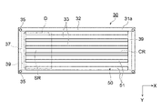
- FIG. FIG. 2 is a top view showing the vapor chamber according to the first embodiment
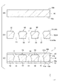
- 3 is a cross-sectional view taken along line III--III showing the vapor chamber of FIG. 2.
- FIG. 4 is a top view of the lower sheet of FIG. 3
- FIG. 5 is a bottom view of the upper sheet of FIG. 3
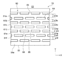
- FIG. 6 is a top view of the wick sheet of FIG. 3
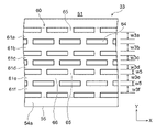
- FIG. 7 is a bottom view of the wick sheet of FIG. 3.
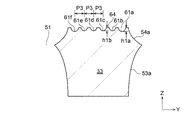
- FIG. 8 is a partially enlarged sectional view of FIG. 3.
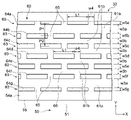
- FIG. 9 is a partially enlarged top view of the liquid flow path shown in FIG. 6.
- FIG. 10(a) to 10(c) are diagrams for explaining the manufacturing method of the vapor chamber according to the first embodiment.
- FIG. 11 is a partially enlarged cross-sectional view showing the liquid flow path portion according to the first modification of the first embodiment.
- FIG. 12 is a partially enlarged top view showing the liquid flow path portion according to the first modification of the first embodiment.
- FIG. 13 is a partially enlarged cross-sectional view showing a liquid flow path portion according to a second modification of the first embodiment.
- FIG. 14 is a partially enlarged top view showing the liquid flow path portion according to the second modification of the first embodiment.
- FIG. 15 is a partially enlarged cross-sectional view showing a liquid flow path portion according to a third modification of the first embodiment.
- FIG. 11 is a partially enlarged cross-sectional view showing the liquid flow path portion according to the first modification of the first embodiment.
- FIG. 12 is a partially enlarged top view showing the liquid flow path portion according to the first modification of the first embodiment.
- FIG. 13
- FIG. 16 is a partially enlarged top view showing the liquid flow path portion according to the third modification of the first embodiment.
- FIG. 17 is a partially enlarged top view showing the liquid flow path portion according to the fourth modification of the first embodiment.
- FIG. 18 is a partially enlarged sectional view of the vapor chamber according to the second embodiment.
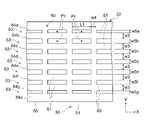
- FIG. 19 is a partially enlarged top view of the liquid channel portion of the wick sheet according to the second embodiment.
- FIG. 20 is a partially enlarged cross-sectional view showing the liquid flow path portion according to the first modification of the second embodiment.
- FIG. 21 is a partially enlarged top view showing the liquid flow path portion according to the first modification of the second embodiment.
- FIG. 22 is a partially enlarged cross-sectional view showing a liquid flow path portion according to a second modification of the second embodiment.
- FIG. 23 is a partially enlarged top view showing a liquid flow path portion according to a second modification of the second embodiment.
- FIG. 24 is a partially enlarged cross-sectional view showing a liquid flow path portion according to a third modified example of the second embodiment.
- FIG. 25 is a partially enlarged top view showing the liquid flow path portion according to the third modification of the second embodiment.
- FIG. 26 is a partially enlarged top view showing the liquid flow path portion according to the fourth modification of the second embodiment.
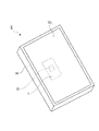
- an electronic device E (for example, a tablet terminal) includes a housing H, a device D housed within the housing H, and a vapor chamber 1 .
- a touch panel display TD is provided on the front surface of the housing H.
- the vapor chamber 1 is housed within the housing H and placed in thermal contact with the device D. As shown in FIG. Thereby, the vapor chamber 1 can receive the heat generated by the device D when the electronic equipment E is used.
- the heat received by the vapor chamber 1 is released to the outside of the vapor chamber 1 via working fluids 2a and 2b, which will be described later. In this way device D is effectively cooled. If the electronic device E is a tablet terminal, the device D corresponds to a central processing unit or the like.
- the vapor chamber 1 has a sealed space 3 filled with working fluids 2a and 2b.
- the vapor chamber 1 is configured so that the working fluids 2a and 2b in the sealed space 3 repeat phase changes to effectively cool the device D of the electronic equipment E described above.
- working fluids 2a and 2b include pure water, ethanol, methanol, acetone, etc., and mixtures thereof.
- the working fluids 2a and 2b may have freeze expandability. That is, the working fluids 2a and 2b may be fluids that expand when frozen.
- the working fluids 2a and 2b having freeze expandability include pure water and an aqueous solution obtained by adding an additive such as alcohol to pure water.
- the vapor chamber 1 includes a lower sheet 10 (first sheet), an upper sheet 20 (second sheet), and a vapor chamber wick sheet (hereinafter simply referred to as a wick sheet 30). ) and .
- the wick sheet 30 is interposed between the lower sheet 10 and the upper sheet 20.
- a lower sheet 10, a wick sheet 30 and an upper sheet 20 are laminated in this order.
- the vapor chamber 1 is generally formed in the shape of a thin flat plate.
- the planar shape of the vapor chamber 1 is arbitrary, it may be rectangular as shown in FIG.
- the planar shape of the vapor chamber 1 may be, for example, a rectangle with one side of 50 mm or more and 200 mm or less and the other side of 150 mm or more and 60 mm or a square with one side of 70 mm or more and 300 mm or less.
- the planar dimension of 1 is arbitrary.
- the planar shape of the vapor chamber 1 is a rectangular shape whose longitudinal direction is the X direction, which will be described later.
- the lower sheet 10, the upper sheet 20 and the wick sheet 30 may have the same planar shape as the vapor chamber 1, as shown in FIGS.
- the planar shape of the vapor chamber 1 is not limited to a rectangular shape, and may be any shape such as a circular shape, an elliptical shape, an L shape, a T shape, or the like.
- the vapor chamber 1 has an evaporation area SR where the working fluids 2a and 2b evaporate and a condensation area CR where the working fluids 2a and 2b condense.
- the evaporation area SR is an area that overlaps with the device D in plan view, and is an area where the device D is attached.
- the evaporation area SR can be arranged anywhere in the vapor chamber 1 .
- an evaporation region SR is formed on one side (left side in FIG. 2) of the vapor chamber 1 in the X direction. Heat from the device D is transferred to the evaporation region SR, and the heat evaporates the liquid working fluid (suitably referred to as working fluid 2b) in the evaporation region SR. Heat from the device D can be transmitted not only to the area overlapping the device D in plan view, but also to the periphery of the area.
- the evaporation region SR includes a region overlapping the device D and a peripheral region thereof in a plan view.
- the planar view means the surface of the vapor chamber 1 that receives heat from the device D (the second upper sheet surface 20b described later of the upper sheet 20) and the surface that releases the received heat (the first upper sheet surface 20b described later of the lower sheet 10). It is seen from a direction orthogonal to the lower seat surface 10a). That is, the planar view corresponds to, for example, a state in which the vapor chamber 1 is viewed from above or a state in which it is viewed from below, as shown in FIG.
- the condensation area CR is an area that does not overlap the device D in plan view, and is an area where the working steam 2a mainly releases heat and condenses.
- the condensation area CR can also be said to be an area around the evaporation area SR. Heat from the working steam 2a is released to the lower sheet 10 in the condensation area CR, and the working steam 2a is cooled and condensed in the condensation area CR.
- the vertical relationship may be disrupted depending on the orientation of the mobile terminal.
- the sheet that receives heat from the device D is referred to as the upper sheet 20 described above, and the sheet that releases the received heat is referred to as the lower sheet 10 described above. Therefore, the following description will be made with the lower sheet 10 arranged on the lower side and the upper sheet 20 arranged on the upper side.
- the lower sheet 10 has a first lower sheet surface 10a positioned opposite to the wick sheet 30 and a side opposite to the first lower sheet surface 10a (that is, the wick sheet 30 side). ) and a second lower seat surface 10b located at .
- the lower sheet 10 may be formed flat as a whole, and the lower sheet 10 may have a uniform thickness as a whole.
- a housing member Ha which constitutes a part of a housing of a mobile terminal or the like, is attached to the first lower seat surface 10a.
- the entire first lower seat surface 10a may be covered with the housing member Ha.
- alignment holes 12 may be provided at the four corners of the lower sheet 10 .
- the upper sheet 20 has a first upper sheet surface 20a provided on the side of the wick sheet 30, a second upper sheet surface 20b located on the opposite side of the first upper sheet surface 20a, have.
- the upper sheet 20 may be formed flat overall, and the upper sheet 20 may have a uniform thickness overall.
- the device D described above is attached to this second upper sheet surface 20b.
- alignment holes 22 may be provided at the four corners of the upper sheet 20 .
- the wick sheet 30 includes a vapor channel portion 50 and a liquid channel portion 60 arranged adjacent to the vapor channel portion 50 .
- the wick sheet 30 also has a first main body surface 31a and a second main body surface 31b opposite to the first main body surface 31a.
- the first body surface 31a is arranged on the lower seat 10 side, and the second body surface 31b is arranged on the upper seat 20 side.
- the second lower sheet surface 10b of the lower sheet 10 and the first main body surface 31a of the wick sheet 30 may be permanently bonded to each other by diffusion bonding.
- the first upper sheet surface 20a of the upper sheet 20 and the second body surface 31b of the wick sheet 30 may be permanently bonded together by diffusion bonding.
- the lower sheet 10, the upper sheet 20 and the wick sheet 30 may be joined by other methods such as brazing instead of diffusion joining as long as they can be joined permanently. Note that the term "permanently bonded" is not bound by a strict meaning.
- “Permanently bonded” means that the bonding between the lower sheet 10 and the wick sheet 30 can be maintained to the extent that the sealing performance of the sealed space 3 can be maintained during the operation of the vapor chamber 1, and the upper sheet 20 and the wick can be maintained. It means that the joint with the sheet 30 is maintained to such an extent that the joint can be maintained.
- the wick sheet 30 according to the present embodiment, as shown in FIGS. 33 and .
- the frame portion 32 and the land portion 33 are portions where the material of the wick sheet 30 remains without being etched in the etching process described later.
- the frame body portion 32 is formed in a rectangular frame shape in plan view.
- a steam channel portion 50 is defined inside the frame portion 32 . That is, the working steam 2 a flows around the land portion 33 inside the frame portion 32 .
- the land portion 33 may extend in an elongated shape in plan view with the X direction (the first direction, the left-right direction in FIG. 6) as the longitudinal direction.
- the planar shape of the land portion 33 may be an elongated rectangular shape.
- the land portions 33 may be arranged parallel to each other with equal intervals in the Y direction (second direction, vertical direction in FIG. 6).
- the working steam 2a is configured to flow around each land portion 33 and be transported toward the condensation region CR. This suppresses obstruction of the flow of the working steam 2a.
- the width w1 (see FIG. 8) of the land portion 33 may be, for example, 30 ⁇ m or more and 3000 ⁇ m or less.
- the width w1 of the land portion 33 is the dimension of the land portion 33 in the Y direction, and means the dimension at the thickest position of the land portion 33 (for example, the position where the protrusion 55 described later exists). .
- the frame body part 32 and each land part 33 are diffusion-bonded to the lower sheet 10 and diffusion-bonded to the upper sheet 20 . This improves the mechanical strength of the vapor chamber 1 .
- a first wall surface 53 a and a second wall surface 54 a of the steam passage 51 which will be described later, form side walls of the land portion 33 .
- the first main body surface 31a and the second main body surface 31b of the wick sheet 30 may be formed flat over the frame portion 32 and each land portion 33 .
- the steam channel portion 50 is mainly a channel through which the steam of the working fluid (suitably referred to as the working steam 2a) passes.
- the steam channel portion 50 extends from the first main body surface 31 a to the second main body surface 31 b and penetrates the wick sheet 30 .
- the steam passage section 50 in this embodiment has a plurality of steam passages 51.
- Each steam passage 51 is formed inside the frame portion 32 and outside the land portion 33 . That is, the steam passage 51 is formed between the frame portion 32 and the land portion 33 and between adjacent land portions 33 .
- the planar shape of each steam passage 51 is an elongated rectangular shape.
- the plurality of land portions 33 partition the steam flow path portion 50 into a plurality of steam passages 51 .
- the steam passage 51 is formed to extend from the first main body surface 31a of the wick sheet 30 to the second main body surface 31b.
- the steam passage 51 may be formed by etching from the first main body surface 31a and the second main body surface 31b of the wick sheet 30 in an etching process to be described later.
- the steam passage 51 has a curved first wall surface 53a and a curved second wall surface 54a.
- the first wall surface 53a is located on the side of the first main body surface 31a, and is curved in a shape that expands toward the second main body surface 31b.
- the second wall surface 54a is positioned on the second main body surface 31b side and is curved in a shape that expands toward the first main body surface 31a.
- the first wall surface 53 a and the second wall surface 54 a meet at a protrusion 55 formed to protrude inside the steam passage 51 .
- the projecting portion 55 may be formed to have an acute angle when viewed in cross section.
- the planar area of the steam passage 51 is minimized at the position where the protrusion 55 exists.
- a width w2 (see FIG. 8) of the steam passage 51 may be, for example, 100 ⁇ m or more, or may be 400 ⁇ m or more.
- the width w2 of the steam passage 51 may be 5000 ⁇ m or less, or may be 1600 ⁇ m or less.
- the width w2 of the steam passage 51 is the width at the narrowest portion of the steam passage 51, and in this case, the distance measured in the width direction (Y direction) at the position where the protrusion 55 exists.
- the width w2 of the steam passage 51 corresponds to the gap between the land portions 33 adjacent to each other in the width direction (Y direction).
- the position of the protrusion 55 in the thickness direction (Z direction) of the wick sheet 30 is shifted toward the second body surface 31b from the intermediate position between the first body surface 31a and the second body surface 31b.
- the distance t5 may be 5% or more, 10% or more, or 20% or more of the thickness t4 of the wick sheet 30, which will be described later. It may be 50% or less, 40% or less, or 30% or less of the thickness t4 of the wick sheet 30 .
- the position of the protrusion 55 in the thickness direction (Z direction) of the wick sheet 30 is not limited to this, and may be an intermediate position between the first main body surface 31a and the second main body surface 31b, or may be positioned more than the intermediate position. The position may be shifted toward the first main body surface 31a. As long as the steam passage 51 penetrates the wick sheet 30 in the thickness direction (Z direction), the position of the protrusion 55 is arbitrary.
- the cross-sectional shape of the steam passage 51 is defined by the projecting portion 55 formed to protrude inward, but it is not limited to this.
- the cross-sectional shape of the steam passage 51 may be trapezoidal, rectangular, or barrel-shaped.
- the steam passage portion 50 including the steam passage 51 configured in this way forms part of the sealed space 3 described above.
- the steam channel portion 50 according to the present embodiment is mainly defined by the lower sheet 10, the upper sheet 20, and the frame portion 32 and the land portion 33 of the wick sheet 30 described above.
- Each steam passage 51 has a relatively large channel cross-sectional area through which the working steam 2a passes.
- FIG. 3 shows the steam passages 51 and the like in an enlarged manner, and the number and arrangement of the steam passages 51 and the like are different from those in FIGS. 2, 6 and 7. ing.
- a support portion 39 that supports the land portion 33 on the frame portion 32 is provided inside the steam flow path portion 50 .
- the support portion 39 supports the land portions 33 adjacent to each other.
- the support portions 39 are provided on both sides of the land portion 33 in the longitudinal direction (X direction).
- the support portion 39 is preferably formed so as not to block the flow of the working steam 2a that diffuses through the steam passage portion 50 .
- the support portion 39 is arranged on the first main body surface 31a side of the wick sheet 30, and a space communicating with the steam channel portion 50 is formed on the second main body surface 31b side.
- the thickness of the support portion 39 can be made thinner than the thickness of the wick sheet 30, and the steam passage 51 can be prevented from being divided in the X direction and the Y direction.
- the support portion 39 may be arranged on the second main body surface 31b side.
- a space communicating with the steam channel portion 50 may be formed on both the surface of the support portion 39 on the first body surface 31a side and the surface on the second body surface 31b side.
- alignment holes 35 may be provided at the four corners of the wick sheet 30 .
- the vapor chamber 1 may further include an injection part 4 for injecting the working fluid 2b into the sealed space 3 at one edge in the X direction.
- the injection part 4 is arranged on the evaporation region SR side.
- the injection part 4 has an injection channel 37 formed in the wick sheet 30 .
- the injection channel 37 is formed on the second main body surface 31b side of the wick sheet 30, and is formed in a concave shape from the second main body surface 31b side.
- the injection channel 37 is in a sealed state.
- the injection channel 37 communicates with the steam channel portion 50 , and the working fluid 2 b is injected into the sealed space 3 through the injection channel 37 .
- the injection channel 37 may communicate with the liquid channel portion 60 depending on the arrangement of the liquid channel portion 60 .
- the injection part 4 is provided at one edge of a pair of edges in the X direction of the vapor chamber 1 is shown, but the present invention is not limited to this. can be placed at any position.
- the injection part 4 may be formed in advance so as to protrude from one side edge of the vapor chamber 1 in the X direction.
- the liquid flow path section 60 is provided on the second body surface 31b of the wick sheet 30. As shown in FIGS. The liquid flow path portion 60 is mainly through which the working liquid 2b passes. The liquid channel portion 60 forms part of the above-described sealed space 3 and communicates with the vapor channel portion 50 .
- the liquid flow path portion 60 is configured as a capillary structure (wick) for transporting the working liquid 2b to the evaporation region SR.
- the liquid flow path portion 60 is provided on the second main body surface 31b of each land portion 33 of the wick sheet 30 .
- the liquid flow path portion 60 may be formed over the entire second main body surface 31 b of each land portion 33 .
- each land portion 33 includes six main liquid flow channel grooves 61a to 61f, but the present invention is not limited to this.
- the number of main grooves for the liquid flow path included in each land portion 33 is arbitrary, and may be, for example, 3 or more and 20 or less.
- Each of the main liquid flow channel grooves 61a to 61f is formed to extend along the longitudinal direction (X direction) of the land portion 33, as shown in FIG.
- the plurality of main liquid flow channel grooves 61a to 61f are arranged parallel to each other.
- the main liquid flow channel grooves 61a to 61f may extend along the curved direction of the land portion 33 in a curved shape. That is, the main liquid flow channel grooves 61a to 61f do not necessarily have to be formed linearly, and do not have to extend parallel to the X direction.
- the main liquid flow channel grooves 61a to 61f have a flow channel cross-sectional area smaller than that of the steam passage 51 of the steam flow channel portion 50 so that the working fluid 2b mainly flows by capillary action.
- the main liquid flow channel grooves 61a-61f are configured to transport the working liquid 2b condensed from the working steam 2a to the evaporation region SR.
- the main liquid flow channel grooves 61a to 61f are spaced apart from each other in the width direction (Y direction).
- the widths of the main liquid flow channel grooves 61a to 61f are not all uniform among the respective main liquid flow channel grooves 61a to 61f.
- the width of the two liquid flow channel main grooves 61a and 61f (hereinafter also referred to as liquid flow channel main grooves 61a and 61f) closest to the steam flow channel portion 50 (steam passage 51) is equal to the width of the other liquid flow channel main groove 61b.
- 61e hereinafter also referred to as the main liquid flow channel grooves 61b to 61e).
- the widths of the main liquid flow channel grooves 61a to 61f are w3a to w3f, respectively, the widths w3a and w3f of the main liquid flow channel grooves 61a and 61f are equal to the widths w3b to w3e of the main liquid flow channel grooves 61b to 61e. (w3a, w3f>w3b-w3e).
- the widths w3a and w3f of the main liquid flow channel grooves 61a and 61f positioned on the outer side in the width direction of each liquid flow channel portion 60 are equal to each other, and the widths w3a and w3f of the main grooves 61a and 61f positioned on the inner side in the width direction of each liquid flow channel portion 60 are equal to each other.
- the cross-sectional shapes (depth, width, etc.) of the plurality of main liquid flow channel grooves 61a to 61f may be line-symmetrical with respect to the center of the land portion 33 in the width direction (Y direction).
- the widths w3a and w3f of the main liquid flow channel grooves 61a and 61f may be different from each other.
- the widths w3b to w3e of the main liquid flow channel grooves 61b to 61e may be different from each other.
- the narrower of the widths w3a and w3f of the main liquid flow grooves 61a and 61f is preferably wider than the widest of the widths w3b to w3e of the main liquid flow grooves 61b to 61e.
- the widths w3a and w3f of the main liquid flow channel grooves 61a and 61f are preferably 1.1 to 1.6 times the widths w3b to w3e of the main liquid flow channel grooves 61b to 61e.
- magnification is 1.1 times or more, the capillary force in the main liquid flow channel grooves 61b to 61e located in the center can be enhanced, and the working liquid 2b can be easily transported toward the evaporation region SR.
- by widening the main liquid flow channel grooves 61a and 61f located on the widthwise outer side of each liquid flow channel portion 60 a large amount of the working fluid 2b can be transported toward the evaporation region SR.
- the working fluid 2b can easily flow from the main liquid flow channel grooves 61a and 61f positioned on the outer side in the width direction of each liquid flow channel portion 60 to the main liquid flow channel grooves 61b to 61e positioned on the inner side in the width direction.
- the widths w3a to w3f of the main liquid flow channel grooves 61a to 61f are the lengths in the direction perpendicular to the longitudinal direction of the land portion 33, and in this case are the dimensions in the Y direction. Widths w3a to w3f of the main liquid flow channel grooves 61a to 61f mean dimensions on the second main body surface 31b. Further, the widths w3a and w3f of the liquid flow channel main grooves 61a and 61f located on the widthwise outer side of each liquid flow channel portion 60 may be, for example, 5.5 ⁇ m or more and 320 ⁇ m or less.
- the widths w3b to w3e of the main liquid flow channel grooves 61b to 61e located on the inner side in the width direction of each liquid flow channel portion 60 may be, for example, 2.2 ⁇ m or more and 290 ⁇ m or less.
- the depths h1a and h1b of the main liquid flow grooves 61a to 61f do not have to be uniform among the main liquid flow grooves 61a to 61f.
- the depth h1a of the main liquid flow channel grooves 61a and 61f positioned on the outer side in the width direction of each liquid flow channel portion 60 is the depth h1b of the main liquid flow channel grooves 61b to 61e positioned on the inner side in the width direction. (h1a>h1b).
- the depths h1a of the main liquid flow channel grooves 61a and 61f are equal to each other, and the depths h1b of the main liquid flow channel grooves 61b to 61e are equal to each other.
- the depths h1a of the liquid flow main grooves 61a and 61f are not limited to this, and may be different from each other.
- the depths h1b of the main liquid flow channel grooves 61b to 61e may be different from each other.
- the depth h1a of the main liquid flow channel grooves 61a and 61f may be, for example, 3.5 ⁇ m or more and 240 ⁇ m or less.
- the depth h1b of the main liquid flow channel grooves 61b to 61e may be, for example, 3 ⁇ m or more and 200 ⁇ m or less.
- the depths h1a and h1b of the main liquid flow channel grooves 61a to 61f are the distances measured in the direction perpendicular to the second main body surface 31b from the second main body surface 31b, and in this case, the dimension in the Z direction. is. Depths h1a and h1b refer to depths at the deepest points of the main liquid flow channel grooves 61a to 61f.
- each liquid channel communication groove 65 extends in a direction different from the X direction.
- each liquid channel connecting groove 65 is formed to extend in the Y direction and is formed perpendicular to the main liquid channel grooves 61a to 61f.
- Some of the liquid flow channel communication grooves 65 are arranged so as to communicate the adjacent liquid flow channel main grooves 61a to 61f.
- the other liquid channel communication groove 65 is arranged so as to communicate the steam channel portion 50 (steam passage 51) with the liquid channel main grooves 61a and 61f closest to the steam channel portion 50.
- the liquid flow channel connecting groove 65 extends from the end portion side of the land portion 33 in the Y direction to the main liquid flow channel grooves 61a and 61f adjacent to the end portion. In this manner, the steam passage 51 of the steam passage portion 50 and the main liquid passage grooves 61a to 61f are communicated with each other.
- the liquid channel communication groove 65 has a channel cross-sectional area smaller than that of the steam passage 51 of the steam channel portion 50 so that the working fluid 2b mainly flows by capillary action.
- Each of the liquid flow channel communication grooves 65 may be arranged at equal intervals in the longitudinal direction (X direction) of the land portion 33 .
- the liquid flow channel connecting groove 65 is also formed by etching, and has wall surfaces (not shown) formed in a curved shape similar to the main liquid flow channel grooves 61a to 61f. is doing.
- the width w4 (dimension in the X direction) of the liquid channel communication groove 65 may be set to 5 ⁇ m or more and 300 ⁇ m or less.
- the depth of the liquid channel communication groove 65 may be 3 ⁇ m or more and 240 ⁇ m or less.
- the main liquid flow channel grooves 61a to 61f include liquid flow channel crossing portions 66 communicating with the liquid flow channel communication grooves 65.
- the liquid channel main grooves 61a to 61f and the liquid channel connecting groove 65 communicate with each other in a T-shape.
- one of the main liquid flow channel grooves 61a to 61f communicates with the liquid flow communication groove 65 on one side (for example, the upper side in FIG. 9) at the liquid flow channel crossing portion 66.
- FIG. As a result, it is possible to prevent the liquid flow channel connecting groove 65 on the other side (for example, the lower side in FIG. 9) from communicating with the main liquid flow channel grooves 61a to 61f at the liquid flow channel crossing portion 66.
- FIG. 1 As a result, the wall surfaces 62 of the main liquid flow channel grooves 61a to 61f are not cut off on both sides in the Y direction at the liquid flow channel crossing portions 66, and one side of the wall surfaces 62 can remain. Therefore, the working fluid 2b in the main liquid flow channel grooves 61a to 61f can be imparted with a capillary action even at the liquid flow channel crossing portion 66, and the driving force of the working fluid 2b toward the evaporation region SR is applied to the liquid flow channel. It is possible to suppress the decrease at the crossing portion 66 .
- a row of protrusions 63 is provided between the main liquid flow channel grooves 61a to 61f adjacent to each other.
- Each projection row 63 includes a plurality of projections 64 (liquid flow path projections) arranged in the X direction.
- the protrusions 64 are provided in the liquid flow path section 60 and protrude from the liquid flow path main grooves 61a to 61f and the liquid flow path communication groove 65 to abut on the upper sheet 20.
- Each convex portion 64 is formed in a rectangular shape in plan view so that the X direction is the longitudinal direction.
- the main liquid flow channel grooves 61a to 61f are arranged between the convex portions 64 adjacent to each other in the Y direction.
- Liquid flow channel communication grooves 65 are arranged between the protrusions 64 that are adjacent to each other in the X direction.
- the liquid flow channel communication groove 65 is formed to extend in the Y direction, and communicates the liquid flow channel main grooves 61a to 61f adjacent to each other in the Y direction. As a result, the working fluid 2b can flow between these main fluid flow channel grooves 61a to 61f.
- the convex portion 64 is a portion where the material of the wick sheet 30 remains without being etched in the etching process described later.
- the planar shape of the convex portion 64 (the shape at the position of the second main body surface 31b of the wick sheet 30) is rectangular.
- the arrangement pitch of the protrusions 64 in the width direction (Y direction) of the liquid flow channel main grooves 61a and 61f is non-uniform among the protrusions 64. That is, the arrangement pitch P1 of the protrusions 64 positioned on both sides in the width direction (Y direction) of each of the main liquid flow channel grooves 61a and 61f is positioned on both sides in the width direction (Y direction) of each of the main liquid flow channel grooves 61b to 61e. It may be wider than the arrangement pitch P2 of the projections 64 (P1>P2).
- the arrangement pitches P1 and P2 of the protrusions 64 are the distances between the Y-direction centers of the protrusions 64 and the Y-direction centers of adjacent protrusions 64 in the X direction, and are distances measured in the Y direction.
- the arrangement pitch P1 of the projections 64 positioned on both sides of the main liquid flow channel grooves 61a and 61f in the Y direction may be, for example, 10 ⁇ m or more and 820 ⁇ m or less.
- the arrangement pitch P2 of the protrusions 64 located on both sides of the main liquid flow channel grooves 61b to 61e in the Y direction may be, for example, 9 ⁇ m or more and 790 ⁇ m or less.
- the convex portions 64 are arranged in a zigzag pattern (alternately). More specifically, the convex portions 64 of the convex portion rows 63 that are adjacent to each other in the Y direction are arranged to be shifted from each other in the X direction. This shift amount may be half the arrangement pitch P4 of the projections 64 in the longitudinal direction (X direction) of the main liquid flow channel grooves 61a to 61f.
- the width w5 (dimension in the Y direction) of the convex portion 64 may be, for example, 5 ⁇ m or more and 500 ⁇ m or less. Also, the width w5 of each convex portion 64 may be uniform between the convex portions 64 .
- the width w5 of the convex portion 64 means the dimension on the second main body surface 31b.
- the arrangement pitch P4 of the protrusions 64 may be uniform between the protrusions 64 .
- the arrangement pitch P4 of the protrusions 64 is the distance between the X-direction center of the protrusion 64 and the X-direction center of the adjacent protrusion 64 in the X direction.
- the arrangement of the convex portions 64 is not limited to the zigzag pattern, and may be arranged in parallel. In this case, the protrusions 64 of the protrusion row 63 adjacent to each other in the Y direction are also aligned in the X direction (see FIG. 17).
- the length L1 (dimension in the X direction) of the protrusions 64 may be uniform between the protrusions 64 . Also, the length L1 of the convex portion 64 is longer than the width w4 of the liquid flow channel communication groove 65 (L1>w4). The length L1 of the convex portion 64 means the maximum dimension in the X direction on the second main body surface 31b.
- the materials constituting the lower sheet 10, the upper sheet 20 and the wick sheet 30 are not particularly limited as long as they have good thermal conductivity. may comprise, for example, copper or copper alloys.
- the thermal conductivity of each sheet 10, 20, 30 can be enhanced, and the heat radiation efficiency of the vapor chamber 1 can be enhanced.
- these sheets 10, 20, 30 may be made of other metal materials such as aluminum and titanium, or other metal alloy materials such as stainless steel, if the desired heat radiation efficiency can be obtained and corrosion can be prevented. can also
- the thickness t1 of the vapor chamber 1 shown in FIG. 3 may be, for example, 100 ⁇ m or more and 2000 ⁇ m or less.
- the thickness t1 of the vapor chamber 1 may be, for example, 100 ⁇ m or more and 2000 ⁇ m or less.
- the thickness t2 of the lower sheet 10 may be, for example, 25 ⁇ m or more and 500 ⁇ m or less. By setting the thickness t2 of the lower sheet 10 to 25 ⁇ m or more, the mechanical strength of the lower sheet 10 can be ensured. On the other hand, by setting the thickness t2 of the lower sheet 10 to 500 ⁇ m or less, it is possible to suppress the thickness t1 of the vapor chamber 1 from increasing. Similarly, the thickness t3 of the upper sheet 20 may be set to be the same as the thickness t2 of the lower sheet 10 . The thickness t3 of the upper sheet 20 and the thickness t2 of the lower sheet 10 may be different.
- the thickness t4 of the wick sheet 30 may be, for example, 50 ⁇ m or more and 1000 ⁇ m or less. By setting the thickness t4 of the wick sheet 30 to 50 ⁇ m or more, the vapor channel portion 50 can be properly secured, and the vapor chamber 1 can be properly operated. On the other hand, by setting the thickness to 1000 ⁇ m or less, it is possible to suppress the thickness t1 of the vapor chamber 1 from increasing.
- FIGS. 10(a) to 10(c) show cross sections similar to the cross sectional view of FIG.
- a flat metal material sheet M including a first material surface Ma and a second material surface Mb is prepared.
- the metal material sheet M is etched from the first material surface Ma and the second material surface Mb as shown in FIG. forming part 60;
- a patterned resist film (not shown) is formed on the first material surface Ma and the second material surface Mb of the metal material sheet M by photolithography. Subsequently, the first material surface Ma and the second material surface Mb of the metal material sheet M are etched through the openings of the patterned resist film. As a result, the first material surface Ma and the second material surface Mb of the metal material sheet M are pattern-etched to form the vapor channel portion 50 and the liquid channel portion 60 as shown in FIG. 10(b). be.
- the etchant for example, an iron chloride-based etchant such as an aqueous ferric chloride solution or a copper chloride-based etchant such as an aqueous copper chloride solution can be used.
- the etching may etch the first material surface Ma and the second material surface Mb of the metal material sheet M at the same time.
- the etching is not limited to this, and the etching of the first material surface Ma and the second material surface Mb may be performed as separate steps.
- the vapor channel portion 50 and the liquid channel portion 60 may be formed by etching at the same time, or may be formed by separate steps.
- etching step by etching the first material surface Ma and the second material surface Mb of the metal material sheet M, a predetermined contour shape as shown in FIGS. 6 and 7 is obtained. That is, the edges of the wick sheet 30 are formed.
- the lower sheet 10 and the upper sheet 20 are joined as a joining process, as shown in FIG. 10(c).
- the lower sheet 10 and the upper sheet 20 may be formed of a rolled material having a desired thickness.
- the lower sheet 10, the wick sheet 30 and the upper sheet 20 are laminated in this order.
- the first main body surface 31a of the wick sheet 30 is overlaid on the second lower sheet surface 10b of the lower sheet 10
- the first upper sheet surface 20a of the upper sheet 20 is superimposed on the second main body surface 31b of the wick sheet 30.
- the alignment hole 12 of the lower sheet 10 see FIG. 4
- the alignment hole 35 of the wick sheet 30 see FIGS. 6 and 7
- the alignment hole 22 of the upper sheet 20 see FIG. 5 are used.
- each sheet 10, 20, 30 is aligned.
- the lower sheet 10, the wick sheet 30 and the upper sheet 20 are temporarily fixed.
- these sheets 10, 20, 30 may be tacked by spot resistance welding, and these sheets 10, 20, 30 may be tacked by laser welding.
- Diffusion bonding is a bonding method as described below. That is, first, the lower sheet 10 and the wick sheet 30 to be joined are brought into close contact with each other, and the wick sheet 30 and the upper sheet 20 are brought into close contact with each other. Next, the lower sheet 10, the wick sheet 30, and the upper sheet 20 are pressurized in the stacking direction and heated in a controlled atmosphere such as a vacuum or an inert gas to utilize diffusion of atoms occurring on the bonding surfaces. to join.
- a controlled atmosphere such as a vacuum or an inert gas
- Diffusion bonding heats the material of each sheet 10, 20, 30 to a temperature close to its melting point, but below its melting point, thereby avoiding melting and deformation of each sheet 10, 20, 30.
- the first main body surface 31 a of the frame portion 32 and the land portions 33 of the wick sheet 30 is diffusion-bonded to the second lower sheet surface 10 b of the lower sheet 10 .
- the second main body surface 31b of the frame portion 32 and each land portion 33 of the wick sheet 30 is diffusion-bonded to the first upper sheet surface 20a of the upper sheet 20 surface.
- the sheets 10, 20, 30 are diffusion-bonded to form the sealed space 3 having the vapor channel portion 50 and the liquid channel portion 60 between the lower sheet 10 and the upper sheet 20. be done.
- the working fluid 2b is injected from the injection part 4 into the sealed space 3.
- the injection channel 37 described above is sealed.
- the injection part 4 may be partially melted to seal the injection channel 37 .
- communication between the sealed space 3 and the outside is cut off, and the hydraulic fluid 2b is enclosed in the sealed space 3, preventing the hydraulic fluid 2b in the sealed space 3 from leaking to the outside.
- the vapor chamber 1 according to the present embodiment is obtained.
- the vapor chamber 1 obtained as described above is installed in a housing H of an electronic device E such as a mobile terminal.
- a device D such as a CPU, which is a device to be cooled, is attached to the second upper sheet surface 20b of the upper sheet 20 (or the vapor chamber 1 is attached to the device D).
- the working fluid 2b in the sealed space 3 moves along the wall surfaces of the sealed space 3, that is, the first wall surface 53a and the second wall surface 54a of the steam passage 51, and the main liquid flow channel grooves 61a to 61a of the liquid flow channel portion 60 by its surface tension. It adheres to the wall surface 62 of 61f and the wall surface of the liquid flow channel communication groove 65 .
- the hydraulic fluid 2b may also adhere to the portion of the second lower seat surface 10b of the lower seat 10 exposed to the steam passage 51 . Furthermore, the hydraulic fluid 2b may also adhere to the portions of the first upper sheet surface 20a of the upper sheet 20 exposed to the vapor passage 51, the main liquid flow channel grooves 61a to 61f, and the liquid flow communication grooves 65. As shown in FIG.
- the working fluid 2b existing in the evaporation region SR receives heat from the device D.
- the received heat is absorbed as latent heat and the working fluid 2b evaporates (vaporizes) to generate the working steam 2a.
- Most of the generated working steam 2a diffuses within the steam passage 51 forming the sealed space 3 (see the solid line arrow in FIG. 6).
- the working steam 2a in each steam passage 51 is separated from the evaporation region SR, and most of the working steam 2a is transported to the relatively low temperature condensation region CR (the right portion in FIGS. 6 and 7).
- the working steam 2a is mainly radiated to the lower sheet 10 and cooled.
- the heat received by the lower seat 10 from the working steam 2a is transferred to the outside air via the housing member Ha (see FIG. 3).
- the working steam 2a By radiating heat to the lower sheet 10 in the condensation area CR, the working steam 2a loses the latent heat absorbed in the evaporation area SR and condenses to produce the working fluid 2b.
- the generated hydraulic fluid 2b adheres to the first wall surface 53a and the second wall surface 54a of each steam passage 51, the second lower seat surface 10b of the lower seat 10, and the first upper seat surface 20a of the upper seat 20. .
- the working fluid 2b continues to evaporate in the evaporation region SR.
- the working fluid 2b in the area other than the evaporation area SR (that is, the condensation area CR) of the liquid flow path portion 60 is transported toward the evaporation area SR by the capillary action of the main liquid flow path main grooves 61a to 61f. (see dashed arrow in FIG. 6).
- the working fluid 2b adhering to the steam passages 51, the second lower seat surface 10b, and the first upper seat surface 20a moves to the liquid flow path portion 60, passes through the liquid flow path connecting groove 65, and flows into the liquid flow path. It enters into the main flow channel grooves 61a to 61f.
- the main liquid flow channel grooves 61a to 61f and the liquid flow communication grooves 65 are filled with the working fluid 2b. Therefore, the working fluid 2b filled therein is smoothly transported toward the evaporation region SR by obtaining a driving force toward the evaporation region SR due to the capillary action of the respective liquid flow channel main grooves 61a to 61f.
- each of the main liquid channel grooves 61a to 61f communicates with the adjacent other main liquid channel grooves 61a to 61f via the corresponding liquid channel communication grooves 65.
- the hydraulic fluid 2b is prevented from flowing between the main liquid flow channel grooves 61a to 61f adjacent to each other, and the occurrence of dryout in the main liquid flow channel grooves 61a to 61f is suppressed. Therefore, a capillary action is imparted to the working fluid 2b in each of the main fluid flow channel grooves 61a to 61f, and the working fluid 2b is smoothly transported toward the evaporation region SR.
- the working fluid 2b that has reached the evaporation region SR receives heat from the device D again and evaporates.
- the working steam 2a evaporated from the working fluid 2b moves through the liquid flow channel communication groove 65 in the evaporation region SR, moves to the steam passage 51 having a large flow passage cross-sectional area, and diffuses in each steam passage 51.
- the working fluids 2a and 2b circulate in the sealed space 3 while repeating phase changes, that is, evaporation and condensation, to transport and release the heat of the device D.
- FIG. As a result, the device D is cooled.
- the widths w3a and w3f of the main liquid flow channel grooves 61a and 61f are wider than the widths w3b to w3e of the main liquid flow channel grooves 61b to 61e.
- the widths w3a and w3f of the main liquid flow channel grooves 61a and 61f positioned on the outer side in the width direction of each liquid flow channel portion 60 are calculated from the widths w3b to w3e of the main liquid flow channel grooves 61b to 61e positioned on the inner side in the width direction. is also wide. Therefore, the capillary force in the main liquid flow channel grooves 61b to 61e located on the inner side in the width direction is enhanced. This makes it easier to transport the working fluid 2b toward the evaporation region SR.
- the widths w3a and w3f of the liquid flow channel main grooves 61a and 61f closest to the steam flow channel portion 50 (steam passage 51) are equal to those of the other liquid flow channel main grooves 61b to 61e. Wider than the widths w3b to w3e.
- the working fluid 2b can be stored in the wide fluid flow main grooves 61a and 61f. As a result, the working fluid 2b can be smoothly condensed from the vapor channel portion 50 toward the liquid channel portion 60, and the cooling capacity of the vapor chamber 1 can be enhanced.
- the depth h1a of the liquid flow channel main grooves 61a and 61f closest to the steam flow channel portion 50 (steam passage 51) is the depth of the other liquid flow channel main grooves 61b to 61e. Deeper than h1b.
- the hydraulic fluid 2b can be stored in the deep main grooves 61a and 61f of the fluid flow path. Therefore, the working fluid 2b can be smoothly condensed from the vapor channel portion 50 toward the liquid channel portion 60, and the cooling capacity of the vapor chamber 1 can be enhanced.
- the arrangement pitch P1 of the protrusions 64 located on both sides in the width direction of the liquid flow channel main grooves 61a and 61f closest to the steam flow channel portion 50 (steam passage 51) is It is wider than the arrangement pitch P2 of the protrusions 64 located on both sides in the width direction of the flow channel main grooves 61b to 61e.
- the width w5 of the protrusions 64 adjacent to the main liquid flow channel grooves 61a and 61f does not become too narrow, so that the bonding strength between the protrusions 64 and the upper sheet 20 can be suppressed from being lowered.
- FIGS. 11 to 17 are diagrams showing wick sheets 30 according to modified examples.
- the same reference numerals are assigned to the same parts as those shown in FIGS. 1 to 10, and detailed description thereof will be omitted.
- the widths w5a to w5c of the protrusions 64 may be uneven among the protrusions 64.
- FIG. the width w5a of the convex portion 64a located inside the main liquid flow channel grooves 61a and 61f in the Y direction (on the side of the main liquid flow channel grooves 61b and 61e) is larger than the width w5a of each liquid flow channel portion 60 in the width direction. It may be narrower than the width w5b of the protrusion 64b positioned inside (w5a ⁇ w5b).
- the width w5a of the protrusion 64a may be, for example, 5 ⁇ m or more and 380 ⁇ m or less
- the width w5b of the protrusion 64b may be, for example, 10 ⁇ m or more and 400 ⁇ m or less.
- the width w5c of the protrusion 64c located on the Y-direction outer side (on the vapor flow path portion 50 side) with respect to the liquid flow path main grooves 61a and 61f is the same as the width w5a of the protrusion 64a or the width w5b of the protrusion 64b. or may be different from w5a or w5b.
- the center-to-center distances P3 in the width direction (Y direction) of the main liquid flow channel grooves 61a to 61f may be equal to each other. That is, the distance between the main liquid flow channel grooves 61a and 61b, the distance between the main liquid flow channel grooves 61b and 61c, the distance between the main liquid flow channel grooves 61d and 61e, and the distance between the main liquid flow channel grooves 61e and 61f distances are equal to each other. In this case, the center-to-center distance P3 may be, for example, 5 ⁇ m or more and 500 ⁇ m or less.
- the center-to-center distance P3 is the shortest distance between the center positions in the width direction (Y direction) of the liquid flow main grooves 61a to 61f adjacent to each other, and is the distance measured in the Y direction.
- the widths w3a and w3f of the liquid flow channel main grooves 61a and 61f located on the width direction outside of each liquid flow channel portion 60 are the widths of the liquid flow channel main grooves 61b to 61e located on the width direction inside. Wider than w3b to w3e.
- the working fluid 2b can be stored in the wide fluid flow main grooves 61a and 61f. As a result, the working fluid 2b can be smoothly condensed from the vapor channel portion 50 toward the liquid channel portion 60, and the cooling capacity of the vapor chamber 1 can be enhanced.
- the widths w3a and w3f of the liquid flow channel main grooves 61a and 61f located on the outside in the width direction of each liquid flow channel portion 60 are equal to each other, and the widths w3a and w3f of the liquid flow channel main groove 61b located on the inside in the width direction are equal to each other.
- An example has been described in which the widths w3b to w3e of .about.61e are equal to each other.
- the widths of the liquid flow channel main grooves 61a to 61f are the widths of the respective liquid flow channel portions 60 from the liquid flow channel main grooves 61a and 61f closest to the vapor flow channel portion 50 (steam passage 51). It may change so as to gradually become narrower toward the main liquid flow channel grooves 61c and 61d positioned inward in the direction.
- the liquid flow channel main grooves 61a and 61f closest to the steam flow channel portion 50 (steam passage 51) are Widths w3a and w3f are the widest. Also, the widths w3c and w3d of the innermost liquid flow channel main grooves 61c and 61d are the narrowest.
- the widths w3b and w3e of the other main liquid flow channel grooves 61b and 61e are the lengths between the widths w3a and w3f of the main liquid flow channel grooves 61a and 61f and the widths w3c and w3d of the main liquid flow channel grooves 61c and 61d. It is That is, the relationships w3a, w3f>w3b, w3e>w3c, w3d are established.
- the widths w3a and w3f of the liquid flow channel main grooves 61a and 61f located on the outer side in the width direction of each liquid flow channel portion 60 are equal to each other, and the widths w3a and w3f are equal to each other, and are located on the inner side in the width direction of each liquid flow channel portion 60.
- the widths w3c and w3d of the main liquid flow channel grooves 61c and 61d are equal to each other.
- the widths w3b and w3e of the main liquid flow channel grooves 61b and 61e located between them are equal to each other.
- the widths w3a and w3f of the main liquid flow channel grooves 61a and 61f may be different from each other.
- the widths w3c and w3d of the main liquid flow channel grooves 61c and 61d may be different from each other.
- the widths w3b and w3e of the main liquid flow channel grooves 61b and 61e may be different from each other.
- Widths w3a and w3f of the main liquid flow grooves 61a and 61f are 1.1 to 1.6 times the widths w3b and w3e of the main liquid flow grooves 61b and 61e adjacent in the width direction. is preferred.
- the widths w3b and w3e of the main liquid flow grooves 61b and 61e are 1.1 to 1.6 times as large as the widths w3c and w3d of the main liquid flow grooves 61c and 61d adjacent in the width direction. is preferred.
- Widths w3a and w3f of the main liquid flow channel grooves 61a and 61f may be, for example, 5.5 ⁇ m or more and 320 ⁇ m or less.
- Widths w3b and w3e of the main liquid flow channel grooves 61b and 61e may be, for example, 3.5 ⁇ m or more and 290 ⁇ m or less. Widths w3c and w3d of the main liquid flow channel grooves 61c and 61d may be, for example, 2.2 ⁇ m or more and 260 ⁇ m or less.
- the depths h1a, h1b, and h1c of the main liquid flow grooves 61a to 61f do not have to be uniform among the main liquid flow grooves 61a to 61f.
- the depth h1a of the liquid flow channel main grooves 61a and 61f positioned outside in the width direction of each liquid flow channel portion 60 is the depth of the liquid flow channel main grooves 61b and 61e adjacent to the width direction inside. It may be deeper than h1b.
- the depth h1b of the main liquid flow channel grooves 61b and 61e may be deeper than the depth h1c of the main liquid flow channel grooves 61c and 61d adjacent in the width direction thereof (h1a>h1b>h1c). .
- the depths h1a of the main liquid flow channel grooves 61a and 61f are equal to each other, and the depths h1b of the main liquid flow channel grooves 61b and 61e are equal to each other.
- the depths h1c of the main liquid flow channel grooves 61c and 61d are equal to each other.
- the depth h1a of the main liquid flow channel grooves 61a and 61f may be, for example, 3.5 ⁇ m or more and 240 ⁇ m or less.
- the depth h1b of the main liquid flow channel grooves 61b and 61e may be, for example, 3.3 ⁇ m or more and 200 ⁇ m or less.
- the depth h1c of the liquid flow main grooves 61c and 61d may be, for example, 3 ⁇ m or more and 150 ⁇ m or less.
- the depth h1a of the main liquid flow channel grooves 61a and 61f may be different from each other, and the depth h1b of the main liquid flow channel grooves 61b and 61e may be different from each other.
- the depths h1c of the main liquid flow channel grooves 61c and 61d may be different from each other.
- the widths of the main liquid flow channel grooves 61a to 61f are adjusted from the main liquid flow channel grooves 61a and 61f closest to the steam flow channel 50 to It gradually narrows toward the main liquid flow channel grooves 61c and 61d located inside.
- the flow of the hydraulic fluid 2b from the main liquid flow channel grooves 61a and 61f positioned on the outer side in the width direction of each liquid flow channel portion 60 toward the main liquid flow channel grooves 61c and 61d positioned on the inner side in the width direction is blocked.
- the condensed working fluid 2b from the steam flow path portion 50 can be stored in the wide liquid flow path main grooves 61a and 61f. Therefore, the working fluid 2b can be smoothly condensed from the vapor channel portion 50 toward the liquid channel portion 60 .
- the widths w3a and w3f of the liquid flow channel main grooves 61a and 61f positioned on the outer side in the width direction of each liquid flow channel portion 60 are equal to each other, and the widths w3a and w3f are equal to each other, and An example has been described in which the widths w3b to w3e of the main liquid flow channel grooves 61b to 61e are equal to each other. However, it is not limited to this.
- the widths of the main liquid flow channel grooves 61b and 61c may be equal to each other.
- the liquid flow channel main grooves 61a and 61f closest to the steam flow channel portion 50 are
- the widths w3a, w3f and the widths w3b, w3e of the liquid flow channel main grooves 61b, 61e that are second closest to the steam flow channel portion 50 (steam passage 51) are the widest.
- the widths w3c and w3d of the liquid flow channel main grooves 61c and 61d located on the innermost side in the width direction are the narrowest. That is, the relationship w3a, w3b, w3e, w3f>w3c, w3d is established.
- the widths w3c and w3d of the main liquid flow channel grooves 61c and 61d may be different from each other.
- two pairs (four) of the liquid flow path main grooves 61a, 61b, 61e, and 61f from the side closest to the steam flow path portion 50 (steam passage 51) among the plurality of liquid flow path main grooves Although the widths w3a, w3b, w3e, and w3f of the widths w3a, w3b, w3e, and w3f of the widths are the same and the widest, the description is not limited to this.
- the widths of three or more pairs (six) or more of the liquid flow main grooves from the side closer to the steam flow channel portion 50 (steam passage 51) may be the same and the widest.
- the widths of the three pairs (six) of liquid flow main grooves from the side closer to the vapor flow channel portion 50 (steam passage 51) are the same and the widest. It's okay to be there.
- the working fluid 2b flows from the main liquid flow channel grooves 61a, 61b, 61e, and 61f positioned on the outer side in the width direction of each liquid flow channel portion 60 toward the main liquid flow channel grooves 61c and 61d positioned on the inner side in the width direction.
- a large amount of the condensed working fluid 2b from the steam flow path portion 50 can be stored in the wide liquid flow path main grooves 61a, 61b, 61e, and 61f.
- the convex portions 64 may be arranged in a grid pattern. Specifically, when a point positioned at the center of the projections 64 in the X direction and the Y direction is defined as a center point Pc, the center points Pc of the plurality of projections 64 are arranged in a grid. That is, the center points Pc of the plurality of convex portions 64 are arranged parallel to each other in the X direction and the Y direction.
- FIGS. 18 to 26 are diagrams showing the second embodiment.
- the same reference numerals are assigned to the same parts as those in FIGS. 1 to 17, and detailed description thereof will be omitted.
- the wick sheet 30 has a first main body surface 31a, a second main body surface 31b, a vapor channel portion 50, and a liquid channel portion 60.
- the liquid flow path portion 60 is provided on the second main body surface 31 b of the wick sheet 30 .
- the liquid flow path portion 60 is mainly through which the working liquid 2b passes.
- the liquid channel portion 60 forms part of the above-described sealed space 3 and communicates with the vapor channel portion 50 .
- the liquid flow path portion 60 is configured as a capillary structure (wick) for transporting the working liquid 2b to the evaporation region SR.
- the liquid flow path portion 60 is provided on the second main body surface 31b of each land portion 33 of the wick sheet 30 .
- the liquid flow path portion 60 may be formed over the entire second main body surface 31 b of each land portion 33 .
- the liquid flow path portion 60 includes a plurality of main liquid flow path grooves 61 through which the working fluid 2b passes and arranged parallel to each other, and a plurality of liquid flow path main grooves 61 communicating with the main liquid flow path grooves 61 . and a channel connecting groove 65 .
- each land portion 33 includes six main liquid flow channel grooves 61, but the present invention is not limited to this.
- the number of main liquid flow channel grooves 61 included in each land portion 33 is arbitrary, and may be, for example, 3 or more and 20 or less.
- Each liquid flow channel main groove 61 is formed to extend along the longitudinal direction (X direction) of the land portion 33, as shown in FIG.
- the plurality of liquid flow channel main grooves 61 are arranged parallel to each other. Note that when the land portion 33 is curved in a plan view, each liquid flow channel main groove 61 may extend in a curved shape along the curved direction of the land portion 33 . That is, each liquid flow channel main groove 61 does not necessarily have to be formed in a straight line, and does not have to extend parallel to the X direction.
- the main liquid channel groove 61 has a channel cross-sectional area smaller than that of the steam passage 51 of the steam channel portion 50 so that the working fluid 2b mainly flows by capillary action.
- the liquid flow path main groove 61 is configured to transport the working fluid 2b condensed from the working steam 2a to the evaporation region SR.
- the main liquid flow channel grooves 61 are spaced apart from each other in the width direction (Y direction).
- the liquid flow channel main groove 61 is formed by etching from the second main body surface 31 b of the wick sheet 30 in the etching process for manufacturing the wick sheet 30 .
- the main liquid flow channel groove 61 has a curved wall surface 62 .
- the wall surface 62 defines the main liquid flow channel groove 61 and is curved in a shape that expands toward the first main body surface 31a.
- the radius of curvature of each wall surface 62 is preferably smaller than the radius of curvature of the second wall surface 54 a of the steam passage 51 .
- the widths w3 of the main grooves 61 of the liquid flow path are all uniform.
- the cross-sectional shapes (depth, width, etc.) of the plurality of main liquid flow channel grooves 61 may be line-symmetrical with respect to the center of the land portion 33 in the width direction (Y direction).
- the width w3 of the main liquid flow channel groove 61 may be different from each other.
- the width w3 of the main liquid flow channel groove 61 is the length in the direction perpendicular to the longitudinal direction of the land portion 33, and in this case, the dimension in the Y direction.
- the width w3 of the main liquid flow channel groove 61 means the dimension on the second main body surface 31b.
- the width w3 of the main liquid flow channel groove 61 may be, for example, 2.2 ⁇ m or more and 320 ⁇ m or less.
- the depths h1 of the main liquid flow channel grooves 61 are uniform among all the main liquid flow channel grooves 61 .
- the depth h1 of the main liquid flow channel grooves 61 is not limited to this, and the depths h1 of the main liquid flow channel grooves 61 may be different from each other.
- the depth h1 of the liquid flow main groove 61 may be, for example, 3 ⁇ m or more and 240 ⁇ m or less.
- the depth h1 of the main liquid flow channel groove 61 is the distance measured in the direction perpendicular to the second main body surface 31b from the second main body surface 31b, and in this case, the dimension in the Z direction.
- the depth h1 is the depth at the deepest point of the main groove 61 of the liquid flow path.
- each liquid channel communication groove 65 extends in a direction different from the X direction.
- each liquid channel connecting groove 65 is formed to extend in the Y direction and is formed perpendicular to the main liquid channel groove 61 .
- Some of the liquid flow channel communication grooves 65 are arranged so as to communicate the liquid flow channel main grooves 61 adjacent to each other.
- Another liquid channel communication groove 65 is arranged so as to communicate the steam channel portion 50 (steam passage 51 ) with the liquid channel main groove 61 closest to the steam channel portion 50 . That is, the liquid flow channel communication groove 65 extends from the end portion side of the land portion 33 in the Y direction to the liquid flow channel main groove 61 adjacent to the end portion. In this manner, the vapor passage 51 of the vapor passage portion 50 and the liquid passage main groove 61 are communicated with each other.
- the liquid channel communication groove 65 has a channel cross-sectional area smaller than that of the steam passage 51 of the steam channel portion 50 so that the working fluid 2b mainly flows by capillary action.
- Each of the liquid flow channel communication grooves 65 may be arranged at equal intervals in the longitudinal direction (X direction) of the land portion 33 .
- the liquid flow path connecting groove 65 is also formed by etching in the same manner as the liquid flow path main groove 61 and has a curved wall surface (not shown) similar to the liquid flow path main groove 61 .
- the width w4 (dimension in the X direction) of the liquid channel communication groove 65 may be 5 ⁇ m or more and 300 ⁇ m or less.
- the depth of the liquid channel communication groove 65 may be 3 ⁇ m or more and 240 ⁇ m or less.
- the liquid flow channel main groove 61 includes a liquid flow channel crossing portion 66 that communicates with the liquid flow channel communication groove 65 .
- the liquid flow path main groove 61 and the liquid flow path communication groove 65 communicate with each other in a T-shape.
- one liquid flow channel main groove 61 communicates with the liquid flow channel connecting groove 65 on one side (for example, the upper side in FIG. 19) at the liquid flow channel crossing portion 66 .
- the liquid channel communication groove 65 on the other side for example, the lower side in FIG. 19
- the wall surface 62 of the main liquid flow channel 61 is not cut off on both sides in the Y direction at the liquid flow channel crossing portion 66, and one side of the wall surface 62 can remain. Therefore, even at the liquid flow path intersection 66, the working fluid 2b in the main liquid flow path groove 61 can be imparted with a capillary action, and the driving force of the working fluid 2b toward the evaporation region SR is applied to the liquid flow path intersection 66. 66 can be suppressed.
- each land portion 33 includes seven rows of convex portions 63 is taken as an example, but the present invention is not limited to this.
- the number of projection rows 63 included in each land portion 33 is arbitrary, and may be, for example, 3 rows or more and 20 rows or less.
- Each projection row 63 is formed to extend along the longitudinal direction (X direction) of each land portion 33, as shown in FIG.
- the plurality of protrusion rows 63 are arranged parallel to each other. Note that when the land portion 33 is curved in a plan view, each convex portion row 63 may extend in a curved shape along the curved direction of the land portion 33 . That is, each projection row 63 does not necessarily have to be formed in a straight line, and does not have to extend parallel to the X direction.
- Each projection row 63 is spaced apart from each other in the width direction (Y direction).
- Each projection row 63 includes a plurality of projections 64a to 64g (liquid flow path projections) arranged in the X direction.
- the convex portions 64a to 64g are arranged in the order of convex portion 64a, convex portion 64b, convex portion 64c, convex portion 64d, convex portion 64e, convex portion 64f, and convex portion 64g from the positive side in the Y direction toward the negative side in the Y direction. It is Of these, the convex portions 64a and 64g are positioned closest to the steam channel portion 50 (steam passage 51) and are located on the outermost side of the liquid channel portion 60 in the Y direction. Further, the convex portion 64d is located furthest from the steam flow path portion 50 (steam passage 51) and is located on the innermost side of the liquid flow path portion 60 in the Y direction.
- the protrusions 64a to 64g are provided in the liquid flow path section 60, protrude from the liquid flow path main groove 61 and the liquid flow path connecting groove 65, and abut the upper sheet 20.
- Each of the projections 64a to 64g is formed in a rectangular shape in plan view so that the X direction is the longitudinal direction.
- the main liquid flow channel grooves 61 are arranged respectively.
- liquid channel communication grooves 65 are arranged between the protrusions 64a to 64g that are adjacent to each other in the X direction.
- the liquid flow channel communication groove 65 is formed to extend in the Y direction, and communicates the liquid flow channel main grooves 61 adjacent to each other in the Y direction. As a result, the working fluid 2b can travel between these main fluid flow channel grooves 61 .
- the convex portions 64 a to 64 g are portions where the material of the wick sheet 30 remains without being etched in the etching process for manufacturing the wick sheet 30 .
- the planar shape of the projections 64a to 64g is rectangular.
- the widths of the protrusions 64a to 64g are not all uniform among the protrusions 64a to 64g. Specifically, the widths of the protrusions 64 a and 64 g (hereinafter also referred to as protrusions 64 a and 64 g ) of the protrusion row 63 closest to the steam flow path portion 50 (steam passage 51 ) are the same as those of the other protrusion rows 63 . It is narrower than the width of the portions 64b to 64f (hereinafter also referred to as convex portions 64b to 64f).
- the widths of the projections 64a to 64g are w5a to w5g
- the widths w5a and w5g of the projections 64a and 64g are narrower than the widths w5b to w5f of the projections 64b to 64f (w5a, w5g ⁇ w5b ⁇ w5f).
- the widths of the plurality of protrusions included in the same protrusion row 63 are uniform.
- the widths w5a and w5g of the protrusions 64a and 64g of the protrusion rows 63 positioned on the outer side in the width direction of each liquid flow path section 60 are equal to each other, and are positioned on the inner side in the width direction of each liquid flow path section 60.
- the widths w5a and w5g of the protrusions 64a and 64g are not limited to this, and may be different from each other.
- the widths w5b to w5f of the projections 64b to 64f may be different from each other. However, it is preferable that the wider one of the widths w5a and w5g of the projections 64a and 64g is narrower than the narrowest one of the widths w5b to w5f of the projections 64b to 64f.
- the widths w5a and w5g of the projections 64a and 64g are preferably 0.3 to 0.95 times the widths w5b to w5f of the projections 64b to 64f.
- the magnification is 0.3 times or more, the shapes of the convex portions 64a and 64g can be stably produced.
- the working fluid 2b can be smoothly evaporated and condensed between the vapor passage 51 and the main groove 61 of the liquid flow path.
- the working fluid 2b can easily flow from the main liquid flow channel groove 61 positioned on the outer side in the width direction of each liquid flow channel portion 60 to the main liquid flow channel groove 61 positioned on the inner side in the width direction.
- the widths w5a to w5g of the convex portions 64a to 64g are the lengths in the direction perpendicular to the longitudinal direction of the land portion 33, and in this case are the dimensions in the Y direction. Widths w5a to w5g of the projections 64a to 64g mean dimensions on the second main body surface 31b.
- the widths w5a and w5g of the protrusions 64a and 64g located on the outer sides in the width direction of each liquid flow path section 60 may be, for example, 1.5 ⁇ m or more and 475 ⁇ m or less.
- the widths w5b to w5f of the protrusions 64b to 64f positioned on the inner side in the width direction of each liquid flow path portion 60 may be, for example, 5 ⁇ m or more and 500 ⁇ m or less.
- the convex portions 64a to 64g are arranged in a zigzag pattern (alternately). More specifically, the protrusions 64a to 64g of the protrusion row 63 that are adjacent to each other in the Y direction are arranged to be offset from each other in the X direction. This shift amount may be half the arrangement pitch of the projections 64a to 64g in the X direction.
- the arrangement of the projections 64a to 64g is not limited to the zigzag pattern, and may be arranged in parallel. In this case, the protrusions 64a to 64g of the protrusion row 63 adjacent to each other in the Y direction are also aligned in the X direction (see FIG. 26).
- the length L1 (dimension in the X direction) of the projections 64a-64g may be uniform among the projections 64a-64g. Also, the length L1 of the projections 64a to 64g is longer than the width w4 of the liquid flow channel communication groove 65 (L1>w4). The length L1 of the projections 64a to 64g means the maximum dimension in the X direction on the second main body surface 31b.
- the working steam 2a generated from the working fluid 2b moves from the liquid flow path portion 60 toward the steam passage 51.
- the working steam 2a passes from the liquid flow channel main groove 61 through the liquid flow channel connecting grooves 65 adjacent to the widthwise outer protrusions 64a and 64g of the respective liquid flow channel portions 60, and into the steam passage 51. leak.
- the working fluid 2b produced from the working steam 2a moves from the steam passage 51 toward the liquid flow path portion 60.
- the working fluid 2b passes through the liquid channel connecting grooves 65 adjacent to the widthwise outer protrusions 64a and 64g of the respective liquid channel portions 60, and enters the liquid channel main grooves 61.
- the widths w5a and w5g of the protrusions 64a and 64g of the protrusion row 63 closest to the steam passage 51 are the same as the protrusions 64b of the other protrusion row 63. It is narrower than the width w5b to w5f of ⁇ 64f. Therefore, the length (distance in the Y direction) of the liquid flow channel communication groove 65 adjacent to the protrusions 64a and 64g is short, and the flow resistance of the liquid flow channel communication groove 65 is low.
- the flow path resistance on the outside in the width direction (Y direction) of the liquid flow path portion 60 is suppressed, and the working steam 2a or the working liquid 2b smoothly flows out or flows between the vapor passage 51 and the liquid flow path portion 60.
- the condensation of the working vapor 2a or the evaporation of the working fluid 2b between the vapor passage 51 and the liquid passage portion 60 can be performed smoothly, and the cooling capacity of the vapor chamber 1 can be enhanced.
- the widths w3 of the plurality of main liquid flow channel grooves 61 are uniform. As a result, the capillary force generated on the working fluid 2b can be made uniform in the width direction of the fluid flow path portion 60 .
- FIGS. 20 to 26 are diagrams showing wick sheets 30 according to modified examples.
- the same reference numerals are given to the same parts as those shown in FIGS. 1 to 19, and detailed descriptions thereof are omitted.
- the width w3a of the liquid flow channel main groove 61a closest to the steam flow channel portion 50 (steam passage 51) is equal to the width w3a of the other liquid flow channel main groove 61b. It may be wider than the width w3b.
- the widths w3a of the two main liquid flow channel grooves 61a closest to the steam flow channel portion 50 (steam passage 51) are equal to each other, and the widths w3b of the other four main liquid flow channel grooves 61b are equal to each other.
- the width w3a of the main liquid flow channel groove 61a is preferably 1.1 to 1.6 times the width w3b of the main liquid flow channel groove 61b.
- the magnification is 1.1 times or more, the capillary force in the central liquid flow channel main groove 61b can be increased, and the working fluid 2b can be easily transported toward the evaporation region SR.
- the magnification is 1.6 times or less, it is possible to suppress a reduction in the transport amount of the working fluid 2b in the liquid flow channel main grooves 61b positioned on the inner side in the width direction of each liquid flow channel portion 60.
- the depth h1a of the liquid flow channel main groove 61a closest to the steam flow channel portion 50 (steam passage 51) is deeper than the depth h1b of the other liquid flow channel main grooves 61b. It's okay to be there.
- the widths w5a and w5g of the protrusions 64a and 64g of the protrusion row 63 closest to the steam passage 51 among the plurality of protrusions 64a to 64g are It is narrower than the width w5b to w5f of 64f. Therefore, the length (distance in the Y direction) of the liquid flow channel communication groove 65 adjacent to the protrusions 64a and 64g is short, and the flow resistance of the liquid flow channel communication groove 65 is low. As a result, the flow path resistance on the outside in the width direction (Y direction) of the liquid flow path portion 60 is suppressed, and the working steam 2a or the working liquid 2b smoothly flows out or flows between the vapor passage 51 and the liquid flow path portion 60. can be made As a result, the condensation of the working vapor 2a or the evaporation of the working fluid 2b between the vapor passage 51 and the liquid passage portion 60 can be performed smoothly, and the cooling capacity of the vapor chamber 1 can be enhanced.
- the width w3a of the liquid flow channel main groove 61a located on the width direction outer side of each liquid flow channel portion 60 is wider than the width w3b of the other liquid flow channel main grooves 61b.
- the width of the convex portions 64a and 64g of the convex portion row 63 closest to the steam passage portion 50 (steam passage 51) among the plurality of convex portions 64a to 64g is w5a and w5g are the narrowest.
- the width w5d of the convex portion 64d of the convex portion row 63 located on the innermost side in the width direction is the widest.
- Widths w5b and w5f of the protrusions 64b and 64f are wider than widths w5a and w5g of the protrusions 64a and 64g, and widths w5c and w5e of the protrusions 64c and 64e are wider than widths w5b and w5f of the protrusions 64b and 64f. wide. That is, the relationships w5a, w5g ⁇ w5b, w5f ⁇ w5c, and w5e ⁇ w5d are established.
- widths w5b and w5f of the protrusions 64b and 64f may be different from each other.
- widths w5c and w5e of the protrusions 64c and 64e may be different from each other.
- Widths w5b to w5f of the projections 64b to 64f are, respectively, widths w5a to w5c and w5e to w5g of the projections 64a to 64c and 64e to 64g adjacent to the outside in the width direction of the liquid flow path portion 60. It is preferable to be 1.1 times or more and 1.5 times or less. That is, the widths w5b and w5f of the projections 64b and 64f are preferably 1.1 to 1.5 times the widths w5a and w5g of the projections 64a and 64g.
- the widths w5c and w5e of the projections 64c and 64e are preferably 1.1 to 1.5 times the widths w5b and w5f of the projections 64b and 64f. Further, the width w5d of the protrusion 64d is preferably 1.1 to 1.5 times the widths w5c and w5e of the protrusions 64c and 64e.
- the widths w5a and w5g of the protrusions 64a and 64g may be, for example, 1.5 ⁇ m or more and 430 ⁇ m or less.
- Widths w5b and w5f of the protrusions 64b and 64f may be, for example, 1.5 ⁇ m or more and 450 ⁇ m or less.
- Widths w5c and w5e of the protrusions 64c and 64e may be, for example, 1.5 ⁇ m or more and 475 ⁇ m or less.
- the width w5d of the convex portion 64d may be, for example, 5 ⁇ m or more and 500 ⁇ m or less.
- the widths w3 of the main liquid flow channel grooves 61 are all uniform.
- the width of the main liquid flow channel grooves 61 is not limited to this, and the widths of the main liquid flow channel grooves 61 may be uneven.
- the widths of the protrusions 64a to 64g are the most inward in the width direction from the protrusions 64a and 64g of the protrusion row 63 closest to the steam passage portion 50 (steam passage 51). It gradually widens toward the convex portion 64d of the convex portion row 63 that is positioned.
- the flow path resistance of the liquid flow path connecting groove 65 on the outer side in the width direction (Y direction) of the liquid flow path section 60 can be suppressed to be lower than the flow path resistance of the liquid flow path connecting groove 65 positioned on the inner side in the width direction. can.
- the working steam 2a or the working liquid 2b can smoothly flow out or flow between the steam passage 51 and the liquid flow path portion 60 .
- the condensation of the working vapor 2a or the evaporation of the working fluid 2b between the vapor passage 51 and the liquid passage portion 60 can be performed smoothly, and the cooling capacity of the vapor chamber 1 can be enhanced.
- the pressure when the water expands inside the liquid flow path portion 60 (for example, around the convex portion 64d) can be relatively easily released in the direction of the steam passage 51, and the convex portions 64a to 64g of deformation can be suppressed.
- the widths of the convex portions 64a and 64g of the convex portion row 63 closest to the steam passage portion 50 (steam passage 51) among the plurality of convex portions 64a to 64g are Widths w5a, w5g and widths w5b, w5f of the protrusions 64b, 64f of the protrusions 64b, 64f of the protrusion row 63 that is second closest to the steam flow path 50 (steam passage 51) are narrowed.
- the widths w5c to w5e of the protrusions 64c to 64e of the protrusion row 63 located on the inner side in the width direction are widened. That is, the relationship w5a, w5b, w5f, w5g>w5c to w5e is established.
- the third modification two pairs (four pieces) of narrow protrusions 64a, 64b, 64f, and 64g are provided.
- the flow path resistance on the outer side in the width direction (Y direction) of the liquid flow path portion 60 is particularly suppressed, and the working steam 2a or the working liquid 2b smoothly flows out between the vapor passage 51 and the liquid flow path portion 60. or can be inflowed.
- the condensation of the working vapor 2a or the evaporation of the working fluid 2b between the vapor passage 51 and the liquid passage portion 60 can be performed smoothly, and the cooling capacity of the vapor chamber 1 can be enhanced.
- the convex portions 64a to 64g may be arranged in a grid pattern.
- the center points Pc of the plurality of projections 64a to 64g are arranged in a grid. That is, the center points Pc of the plurality of protrusions 64a to 64g are arranged parallel to each other in the X direction and the Y direction.
- the channel resistance of the liquid channel communication groove 65 on the outside in the width direction (Y direction) of the liquid channel portion 60 is suppressed, and between the steam passage 51 and the liquid channel portion 60, the working steam 2a or the working liquid 2b can flow out or flow smoothly.
Landscapes
- Engineering & Computer Science (AREA)
- Physics & Mathematics (AREA)
- Thermal Sciences (AREA)
- Microelectronics & Electronic Packaging (AREA)
- Life Sciences & Earth Sciences (AREA)
- Sustainable Development (AREA)
- Mechanical Engineering (AREA)
- General Engineering & Computer Science (AREA)
- General Physics & Mathematics (AREA)
- Computer Hardware Design (AREA)
- Power Engineering (AREA)
- Condensed Matter Physics & Semiconductors (AREA)
- Cooling Or The Like Of Semiconductors Or Solid State Devices (AREA)
Abstract
ベーパーチャンバ(1)は、第1シート(10)と、第2シート(20)と、ウィックシート(30)と、を備えている。ウィックシート(30)は、第1本体面(31a)と、第2本体面(31b)と、第1本体面(31a)から第2本体面(31b)に延び、作動流体の蒸気(2a)が通る蒸気流路部(50)と、第2本体面(31b)に設けられ、蒸気流路部(50)と連通して液状の作動流体(2b)が通る液流路部(60)と、を有する。液流路部(60)は、液状の作動流体(2b)が通る複数の液流路主流溝(61a~61f)を有し、複数の液流路主流溝(61a~61f)のうち、蒸気流路部(50に最も近い液流路主流溝(61a、61f)の幅(w3a、w3f)は、他の液流路主流溝(61b~61e)の幅(w3b~w3e)よりも広い。
Description
本開示は、ベーパーチャンバ、ベーパーチャンバ用のウィックシート及び電子機器に関する。
携帯端末やタブレット端末といったモバイル端末等で使用される中央演算処理装置(CPU)や発光ダイオード(LED)、パワー半導体等は、発熱を伴うデバイスである。発熱を伴うデバイスは、ヒートパイプ等の放熱用部材によって冷却されている。近年では、モバイル端末等の薄型化のために、放熱用部材の薄型化も求められている。このためヒートパイプより薄型化を図ることができるベーパーチャンバの開発が進められている。ベーパーチャンバ内には、作動流体が封入されている。この作動流体がデバイスの熱を吸収、拡散することで、デバイスの冷却を行っている。例えば、特許文献1には、金属箔シートを2枚以上積み重ねたシート型ヒートパイプが開示されている。
より具体的には、ベーパーチャンバ内の作動流体は、デバイスに近接した部分(蒸発部)でデバイスから熱を受けて蒸発して蒸気(作動蒸気)になる。その作動蒸気は、蒸気流路部内で蒸発部から離れる方向に拡散して冷却され、凝縮して液状になる。ベーパーチャンバ内には、毛細管構造(ウィック)としての液流路部が設けられている。凝縮して液状になった作動流体(作動液)は、蒸気流路部から液流路部に入り込み、液流路部を流れて蒸発部に向かって輸送される。そして、作動液は、再び蒸発部で熱を受けて蒸発する。このようにして、作動流体が、相変化、すなわち蒸発と凝縮とを繰り返しながらベーパーチャンバ内を還流することによりデバイスの熱を移動させ、放熱効率を高めている。
本実施の形態は、冷却能力に優れたベーパーチャンバ、ベーパーチャンバ用のウィックシート及びこれらを備えた電子機器を提供することを目的とする。
本実施の形態によるベーパーチャンバは、作動流体が封入されたベーパーチャンバであって、第1シートと、第2シートと、前記第1シートと前記第2シートとの間に介在されたウィックシートと、を備え、前記ウィックシートは、第1本体面と、前記第1本体面とは反対側に位置する第2本体面と、前記第1本体面から前記第2本体面に延び、前記作動流体の蒸気が通る蒸気流路部と、前記第2本体面に設けられ、前記蒸気流路部と連通して液状の前記作動流体が通る液流路部と、を有し、前記液流路部は、液状の前記作動流体が通るとともに互いに並走して配置された複数の液流路主流溝を有し、前記複数の液流路主流溝のうち、前記蒸気流路部に最も近い液流路主流溝の幅は、他の液流路主流溝の幅よりも広い。
本実施の形態によるベーパーチャンバにおいて、前記蒸気流路部に最も近い液流路主流溝の幅は、前記他の液流路主流溝の幅の、1.1倍以上1.6倍以下であっても良い。
本実施の形態によるベーパーチャンバにおいて、前記蒸気流路部に最も近い液流路主流溝の深さは、前記他の液流路主流溝の深さよりも深くても良い。
本実施の形態によるベーパーチャンバにおいて、前記複数の液流路主流溝の幅方向における中心間距離が互いに等しくても良い。
本実施の形態によるベーパーチャンバにおいて、互いに隣り合う前記液流路主流溝の間に、凸部列が設けられ、各凸部列は、それぞれ複数の凸部を有し、前記液流路主流溝の長手方向における各凸部の配列ピッチは、各凸部間で均一となっていても良い。
本実施の形態によるベーパーチャンバにおいて、前記複数の液流路主流溝の幅が、前記蒸気流路部に最も近い液流路主流溝から、前記液流路部の幅方向内側に位置する液流路主流溝に向けて徐々に狭くなっていても良い。
本実施の形態によるウィックシートは、ベーパーチャンバ用のウィックシートであって、第1本体面と、前記第1本体面とは反対側に位置する第2本体面と、前記第1本体面から前記第2本体面に延び、作動流体の蒸気が通る蒸気流路部と、前記第2本体面に設けられ、前記蒸気流路部と連通して液状の前記作動流体が通る液流路部と、を有し、前記液流路部は、液状の前記作動流体が通るとともに互いに並走して配置された複数の液流路主流溝を有し、前記複数の液流路主流溝のうち、前記蒸気流路部に最も近い液流路主流溝の幅は、他の液流路主流溝の幅よりも広い。
本実施の形態によるウィックシートにおいて、前記蒸気流路部に最も近い液流路主流溝の幅は、前記他の液流路主流溝の幅の、1.1倍以上1.6倍以下であっても良い。
本実施の形態によるウィックシートにおいて、前記蒸気流路部に最も近い液流路主流溝の深さは、前記他の液流路主流溝の深さよりも深くても良い。
本実施の形態によるウィックシートにおいて、前記複数の液流路主流溝の幅方向における中心間距離が互いに等しくても良い。
本実施の形態によるウィックシートにおいて、互いに隣り合う前記液流路主流溝の間に、凸部列が設けられ、各凸部列は、それぞれ複数の凸部を有し、前記液流路主流溝の長手方向における各凸部の配列ピッチは、各凸部間で均一となっていても良い。
本実施の形態によるウィックシートにおいて、前記複数の液流路主流溝の幅が、前記蒸気流路部に最も近い液流路主流溝から、前記液流路部の幅方向内側に位置する液流路主流溝に向けて徐々に狭くなっていても良い。
本実施の形態による電子機器は、ハウジングと、前記ハウジング内に収容されたデバイスと、前記デバイスに熱的に接触した、本実施の形態によるベーパーチャンバと、を備えている。
本開示の実施の形態によれば、冷却能力に優れたベーパーチャンバを提供できる。
本実施の形態によるベーパーチャンバは、作動流体が封入されたベーパーチャンバであって、第1シートと、第2シートと、前記第1シートと前記第2シートとの間に介在されたウィックシートと、を備え、前記ウィックシートは、第1本体面と、前記第1本体面とは反対側に位置する第2本体面と、前記第1本体面から前記第2本体面に延び、前記作動流体の蒸気が通る蒸気流路部と、前記第2本体面に設けられ、前記蒸気流路部と連通して液状の前記作動流体が通る液流路部と、を有し、前記液流路部は、液状の前記作動流体が通るとともに互いに並走して配置された複数の液流路主流溝を有し、互いに隣り合う前記液流路主流溝の間に、凸部列が設けられ、各凸部列は、それぞれ複数の凸部を有し、前記蒸気流路部に最も近い凸部列の凸部の幅は、他の凸部列の凸部の幅よりも狭い。
本実施の形態によるベーパーチャンバにおいて、前記蒸気流路部に最も近い凸部列の凸部の幅は、前記他の凸部列の凸部の幅の、0.3倍以上0.95倍以下であっても良い。
本実施の形態によるベーパーチャンバにおいて、前記蒸気流路部に最も近い凸部列の凸部と当該凸部列に隣接する凸部列の凸部との配列ピッチは、前記他の凸部列の凸部同士の配列ピッチよりも狭くても良い。
本実施の形態によるベーパーチャンバにおいて、前記複数の液流路主流溝の幅は、互いに均一となっていても良い。
本実施の形態によるベーパーチャンバにおいて、前記複数の液流路主流溝のうち、前記蒸気流路部に最も近い液流路主流溝の幅は、他の液流路主流溝の幅よりも広くても良い。
本実施の形態によるベーパーチャンバにおいて、前記複数の凸部の幅が、前記蒸気流路部に最も近い凸部列の凸部から、前記液流路部の幅方向内側に位置する凸部列の凸部に向けて徐々に広くなっていても良い。
本実施の形態によるウィックシートは、ベーパーチャンバ用のウィックシートであって、第1本体面と、前記第1本体面とは反対側に位置する第2本体面と、前記第1本体面から前記第2本体面に延び、作動流体の蒸気が通る蒸気流路部と、前記第2本体面に設けられ、前記蒸気流路部と連通して液状の前記作動流体が通る液流路部と、を有し、前記液流路部は、液状の前記作動流体が通るとともに互いに並走して配置された複数の液流路主流溝を有し、互いに隣り合う前記液流路主流溝の間に、凸部列が設けられ、各凸部列は、それぞれ複数の凸部を有し、前記蒸気流路部に最も近い凸部列の凸部の幅は、他の凸部列の凸部の幅よりも狭い。
本実施の形態によるウィックシートにおいて、前記蒸気流路部に最も近い凸部列の凸部の幅は、前記他の凸部列の凸部の幅の、0.3倍以上0.95倍以下であっても良い。
本実施の形態によるウィックシートにおいて、前記蒸気流路部に最も近い凸部列の凸部と当該凸部列に隣接する凸部列の凸部との配列ピッチは、前記他の凸部列の凸部同士の配列ピッチよりも狭くても良い。
本実施の形態によるウィックシートにおいて、前記複数の液流路主流溝の幅は、互いに均一となっていても良い。
本実施の形態によるウィックシートにおいて、前記複数の液流路主流溝のうち、前記蒸気流路部に最も近い液流路主流溝の幅は、他の液流路主流溝の幅よりも広くても良い。
本実施の形態によるウィックシートにおいて、前記複数の凸部の幅が、前記蒸気流路部に最も近い凸部列の凸部から、前記液流路部の幅方向内側に位置する凸部列の凸部に向けて徐々に広くなっていても良い。
本実施の形態による電子機器は、ハウジングと、前記ハウジング内に収容されたデバイスと、前記デバイスに熱的に接触した、本実施の形態によるベーパーチャンバと、を備えている。
本開示の実施の形態によれば、ベーパーチャンバの冷却能力を高めることができる。
(第1の実施の形態)
以下、図1乃至図17を参照して第1の実施の形態について説明する。なお、本明細書に添付する図面においては、図示と理解のしやすさの便宜上、適宜縮尺及び縦横の寸法比等を、実物のそれらから変更し誇張してある。
以下、図1乃至図17を参照して第1の実施の形態について説明する。なお、本明細書に添付する図面においては、図示と理解のしやすさの便宜上、適宜縮尺及び縦横の寸法比等を、実物のそれらから変更し誇張してある。
また、本明細書において用いる、形状や幾何学的条件及び物理的特性並びにそれらの程度を特定する、例えば、「平行」、「直交」、「同一」等の用語や長さや角度並びに物理的特性の値等については、厳密な意味に縛られない。これらの用語又は数値は、同様の機能を期待し得る程度の範囲を含めて解釈することとする。さらに、図面においては、明瞭にするために、同様の機能を期待し得る複数の部分の形状を、規則的に記載している。なお、厳密な意味に縛られることなく、当該機能を期待できる範囲内で、当該部分の形状は互いに異なっていてもよい。また、図面においては、部材同士の接合面などを示す境界線を、便宜上、単なる直線で示している。境界線は、厳密な直線であることに縛られることはない。所望の接合性能を期待できる範囲内で、当該境界線の形状は任意である。
図1乃至図10を用いて、本実施の形態におけるベーパーチャンバ、ベーパーチャンバ用のウィックシート及び電子機器について説明する。本実施の形態におけるベーパーチャンバ1は、電子機器Eに収容された発熱体としてのデバイスDを冷却するために、電子機器Eに搭載される装置である。デバイスDの例としては、携帯端末やタブレット端末といったモバイル端末等で使用される、発熱を伴う電子デバイス(被冷却装置)が挙げられる。発熱を伴う電子デバイスとしては、中央演算処理装置(CPU)、発光ダイオード(LED)、パワー半導体等の発熱を伴う電子デバイス(被冷却装置)が挙げられる。
ここではまず、本実施の形態によるベーパーチャンバ1が搭載される電子機器Eについて、タブレット端末を例にとって説明する。図1に示すように、電子機器E(例えばタブレット端末)は、ハウジングHと、ハウジングH内に収容されたデバイスDと、ベーパーチャンバ1と、を備えている。図1に示す電子機器Eでは、ハウジングHの前面にタッチパネルディスプレイTDが設けられている。ベーパーチャンバ1は、ハウジングH内に収容されて、デバイスDに熱的に接触するように配置される。これにより、電子機器Eの使用時にデバイスDで発生する熱をベーパーチャンバ1が受けることができる。ベーパーチャンバ1が受けた熱は、後述する作動流体2a、2bを介してベーパーチャンバ1の外部に放出される。このようにして、デバイスDは効果的に冷却される。電子機器Eがタブレット端末である場合には、デバイスDは、中央演算処理装置等に相当する。
次に、本実施の形態によるベーパーチャンバ1について説明する。図2及び図3に示すように、ベーパーチャンバ1は、作動流体2a、2bが封入された密封空間3を有している。ベーパーチャンバ1は、密封空間3内の作動流体2a、2bが相変化を繰り返すことにより、上述した電子機器EのデバイスDを効果的に冷却するように構成されている。作動流体2a、2bの例としては、純水、エタノール、メタノール、アセトン等、及びそれらの混合液が挙げられる。なお、作動流体2a、2bは、凍結膨張性を有していてもよい。すなわち、作動流体2a、2bは、凍結時に膨張する流体であってもよい。凍結膨張性を有する作動流体2a、2bの例としては、純水、又は純水にアルコールなどの添加物を加えた水溶液等が挙げられる。
図2及び図3に示すように、ベーパーチャンバ1は、下側シート10(第1シート)と、上側シート20(第2シート)と、ベーパーチャンバ用のウィックシート(以下、単にウィックシート30と記す)と、を備えている。ウィックシート30は、下側シート10と上側シート20との間に介在されている。本実施の形態によるベーパーチャンバ1は、下側シート10、ウィックシート30及び上側シート20が、この順番で積層されている。
ベーパーチャンバ1は、概略的に薄い平板状に形成されている。ベーパーチャンバ1の平面形状は任意であるが、図2に示すような矩形状であってもよい。ベーパーチャンバ1の平面形状は、例えば、1辺が50mm以上200mm以下で他の辺が150mm以上60mmの長方形であってもよく、1辺が70mm以上300mm以下の正方形であってもよく、ベーパーチャンバ1の平面寸法は任意である。本実施の形態では、一例として、ベーパーチャンバ1の平面形状が、後述するX方向を長手方向とする矩形状である例について説明する。この場合、図4乃至図7に示すように、下側シート10、上側シート20及びウィックシート30は、ベーパーチャンバ1と同様の平面形状を有していてもよい。また、ベーパーチャンバ1の平面形状は、矩形状に限られることはなく、円形状、楕円形状、L字形状、T字形状など、任意の形状とすることができる。
図2に示すように、ベーパーチャンバ1は、作動流体2a、2bが蒸発する蒸発領域SRと、作動流体2a、2bが凝縮する凝縮領域CRと、を有している。
蒸発領域SRは、平面視でデバイスDと重なる領域であり、デバイスDが取り付けられる領域である。蒸発領域SRは、ベーパーチャンバ1の任意の場所に配置できる。本実施の形態においては、ベーパーチャンバ1のX方向における一側(図2における左側)に、蒸発領域SRが形成されている。蒸発領域SRにデバイスDからの熱が伝わり、この熱によって液状の作動流体(適宜、作動液2bと記す)が蒸発領域SRにおいて蒸発する。デバイスDからの熱は、平面視でデバイスDに重なる領域だけではなく、当該領域の周辺にも伝わり得る。このため、蒸発領域SRは、平面視で、デバイスDに重なっている領域とその周辺の領域とを含む。ここで平面視とは、ベーパーチャンバ1がデバイスDから熱を受ける面(上側シート20の後述する第2上側シート面20b)及び受けた熱を放出する面(下側シート10の後述する第1下側シート面10a)に直交する方向から見た状態である。すなわち平面視とは、例えば、図2に示すように、ベーパーチャンバ1を上方から見た状態、又は下方から見た状態に相当している。
凝縮領域CRは、平面視でデバイスDと重ならない領域であって、主として作動蒸気2aが熱を放出して凝縮する領域である。凝縮領域CRは、蒸発領域SRの周囲の領域ということもできる。凝縮領域CRにおいて作動蒸気2aからの熱が下側シート10に放出され、作動蒸気2aが凝縮領域CRにおいて冷却されて凝縮する。
なお、ベーパーチャンバ1がモバイル端末内に設置される場合、モバイル端末の姿勢によっては、上下関係が崩れる場合もある。しかしながら、本実施の形態では、便宜上、デバイスDから熱を受けるシートを上述の上側シート20と称し、受けた熱を放出するシートを上述の下側シート10と称する。このため、下側シート10が下側に配置され、上側シート20が上側に配置された状態で、以下説明する。
図3に示すように、下側シート10は、ウィックシート30とは反対側に位置する第1下側シート面10aと、第1下側シート面10aとは反対側(すなわちウィックシート30の側)に位置する第2下側シート面10bと、を有している。下側シート10は、全体的に平坦状に形成されていてもよく、下側シート10は全体的に一定の厚さを有していてもよい。この第1下側シート面10aに、モバイル端末等のハウジングの一部を構成するハウジング部材Haが取り付けられる。第1下側シート面10aの全体が、ハウジング部材Haで覆われてもよい。図4に示すように、下側シート10の四隅に、アライメント孔12が設けられていてもよい。
図3に示すように、上側シート20は、ウィックシート30の側に設けられた第1上側シート面20aと、第1上側シート面20aとは反対側に位置する第2上側シート面20bと、を有している。上側シート20は、全体的に平坦状に形成されていてもよく、上側シート20は全体的に一定の厚さを有していてもよい。この第2上側シート面20bに、上述のデバイスDが取り付けられる。図5に示すように、上側シート20の四隅に、アライメント孔22が設けられていてもよい。
図3に示すように、ウィックシート30は、蒸気流路部50と、蒸気流路部50に隣接して配置された液流路部60とを備えている。またウィックシート30は、第1本体面31aと、第1本体面31aとは反対側に位置する第2本体面31bと、を有している。第1本体面31aは、下側シート10の側に配置されており、第2本体面31bは、上側シート20の側に配置されている。
下側シート10の第2下側シート面10bとウィックシート30の第1本体面31aとは、拡散接合で、互いに恒久的に接合されていてもよい。同様に、上側シート20の第1上側シート面20aとウィックシート30の第2本体面31bとは、拡散接合で、互いに恒久的に接合されていてもよい。なお、下側シート10、上側シート20及びウィックシート30は、拡散接合ではなく、恒久的に接合できれば、ろう付け等の他の方式で接合されていてもよい。なお、「恒久的に接合」という用語は、厳密な意味に縛られることはない。「恒久的に接合」とは、ベーパーチャンバ1の動作時に、密封空間3の密封性を維持可能な程度に、下側シート10とウィックシート30との接合を維持できるとともに、上側シート20とウィックシート30との接合を維持できる程度に接合されていることを意味する。
本実施の形態によるウィックシート30は、図3、図6及び図7に示すように、平面視で矩形枠状に形成された枠体部32と、枠体部32内に設けられたランド部33と、を有している。枠体部32及びランド部33は、後述するエッチング工程においてエッチングされることなく、ウィックシート30の材料が残る部分である。本実施の形態では、枠体部32は、平面視で、矩形枠状に形成されている。枠体部32の内側に、蒸気流路部50が画定されている。すなわち、枠体部32の内側であって、ランド部33の周囲を作動蒸気2aが流れるようになっている。
本実施の形態では、ランド部33は、平面視で、X方向(第1方向、図6における左右方向)を長手方向として細長状に延びていてもよい。ランド部33の平面形状は、細長の矩形形状になっていてもよい。また、各ランド部33は、Y方向(第2方向、図6における上下方向)において等間隔に離間して、互いに平行に配置されていてもよい。各ランド部33の周囲を作動蒸気2aが流れて、凝縮領域CRに向かって輸送されるように構成されている。これにより、作動蒸気2aの流れが妨げられることを抑制している。ランド部33の幅w1(図8参照)は、例えば、30μm以上3000μm以下であってもよい。ここで、ランド部33の幅w1は、Y方向におけるランド部33の寸法であって、ランド部33の最も太い位置(例えば、後述する突起部55が存在する位置)における寸法を意味している。
枠体部32及び各ランド部33は、下側シート10に拡散接合されるとともに、上側シート20に拡散接合される。これにより、ベーパーチャンバ1の機械的強度を向上させている。後述する蒸気通路51の第1壁面53a及び第2壁面54aは、ランド部33の側壁を構成している。ウィックシート30の第1本体面31a及び第2本体面31bは、枠体部32及び各ランド部33にわたって、平坦状に形成されていてもよい。
蒸気流路部50は、主として、作動流体の蒸気(適宜、作動蒸気2aと記す)が通る流路である。蒸気流路部50は、第1本体面31aから第2本体面31bに延びており、ウィックシート30を貫通している。
図6及び図7に示すように、本実施の形態における蒸気流路部50は、複数の蒸気通路51を有している。各蒸気通路51は、枠体部32の内側であってランド部33の外側に形成されている。すなわち蒸気通路51は、枠体部32とランド部33との間、及び互いに隣り合うランド部33同士の間に形成されている。各蒸気通路51の平面形状は、細長の矩形形状になっている。複数のランド部33によって、蒸気流路部50は、複数の蒸気通路51に区画されている。
図3に示すように、蒸気通路51は、ウィックシート30の第1本体面31aから第2本体面31bにわたって延びるように形成されている。
蒸気通路51は、後述するエッチング工程において、ウィックシート30の第1本体面31a及び第2本体面31bからそれぞれエッチングされることによって形成されても良い。この場合、蒸気通路51は、図8に示すように、湾曲状に形成された第1壁面53aと湾曲状に形成された第2壁面54aとを有している。第1壁面53aは、第1本体面31a側に位置しており、第2本体面31bに向かって膨らむような形状で湾曲している。第2壁面54aは、第2本体面31b側に位置しており、第1本体面31aに向かって膨らむような形状で湾曲している。第1壁面53a及び第2壁面54aは、蒸気通路51の内側に張り出すように形成された突起部55において合流している。突起部55は、断面視で鋭角的に形成されていても良い。突起部55が存在する位置において、蒸気通路51の平面面積が最小になっている。蒸気通路51の幅w2(図8参照)は、例えば、100μm以上であってもよく、400μm以上であってもよい。蒸気通路51の幅w2は、5000μm以下であってもよく、1600μm以下であってもよい。ここで、蒸気通路51の幅w2とは、蒸気通路51の最も狭い部分における幅であり、この場合は、突起部55が存在する位置において幅方向(Y方向)に測定した距離をいう。また蒸気通路51の幅w2は、幅方向(Y方向)において互いに隣り合うランド部33の間のギャップに相当する。
ウィックシート30の厚み方向(Z方向)における突起部55の位置は、第1本体面31aと第2本体面31bとの中間位置よりも第2本体面31bにずれている。突起部55と第2本体面31bとの距離をt5としたとき、距離t5は、後述するウィックシート30の厚さt4の5%以上、10%以上、又は20%以上であっても良く、ウィックシート30の厚さt4の50%以下、40%以下、又は30%以下であっても良い。なお、これに限らず、ウィックシート30の厚み方向(Z方向)における突起部55の位置は、第1本体面31aと第2本体面31bとの中間位置であってもよく、中間位置よりも第1本体面31a側にずれた位置でもよい。蒸気通路51がウィックシート30の厚み方向(Z方向)に貫通していれば、突起部55の位置は任意である。
また、本実施の形態では、蒸気通路51の断面形状が、内側に張り出すように形成された突起部55によって画定されているが、これに限られることはない。例えば、蒸気通路51の断面形状は、台形形状や矩形形状であってもよく、あるいは樽形の形状になっていてもよい。
このように構成された蒸気通路51を含む蒸気流路部50は、上述した密封空間3の一部を構成している。図3に示すように、本実施の形態による蒸気流路部50は、主として、下側シート10と、上側シート20と、上述したウィックシート30の枠体部32及びランド部33によって画定されている。各蒸気通路51は、作動蒸気2aが通るように比較的大きな流路断面積を有している。
ここで、図3は、図面を明瞭にするために、蒸気通路51などを拡大して示しており、これらの蒸気通路51などの個数や配置は、図2、図6及び図7とは異なっている。
ところで、図6及び図7に示すように、蒸気流路部50内に、ランド部33を枠体部32に支持する支持部39が設けられている。支持部39は、互いに隣り合うランド部33同士を支持する。支持部39は、長手方向(X方向)においてランド部33の両側に設けられている。支持部39は、蒸気流路部50を拡散する作動蒸気2aの流れを妨げないように形成されていることが好ましい。この場合、支持部39は、ウィックシート30の第1本体面31a側に配置され、第2本体面31b側には、蒸気流路部50に連通する空間が形成されている。これにより、支持部39の厚さをウィックシート30の厚さよりも薄くすることができ、蒸気通路51が、X方向及びY方向において分断されることを防止できる。しかしながら、これに限らず、支持部39は、第2本体面31b側に配置されていても良い。また、支持部39の第1本体面31a側の面及び第2本体面31b側の面の両方に、蒸気流路部50に連通する空間が形成されるようにしてもよい。
図6及び図7に示すように、ウィックシート30の四隅に、アライメント孔35が設けられていてもよい。
また、図2に示すように、ベーパーチャンバ1は、X方向における一側の端縁に、密封空間3に作動液2bを注入する注入部4を更に備えていてもよい。図2に示す形態では、注入部4は、蒸発領域SRの側に配置されている。注入部4は、ウィックシート30に形成された注入流路37を有する。この注入流路37は、ウィックシート30の第2本体面31b側に形成されており、第2本体面31b側から凹状に形成されている。ベーパーチャンバ1の完成後、注入流路37は封止された状態となっている。また、注入流路37は、蒸気流路部50に連通しており、作動液2bは、注入流路37を通過して密封空間3に注入される。なお、液流路部60の配置によっては、注入流路37は液流路部60に連通させるようにしてもよい。
なお、本実施の形態では、注入部4は、ベーパーチャンバ1のX方向における一対の端縁のうちの一側の端縁に設けられている例が示されているが、これに限られることはなく、任意の位置に設けることができる。なお、注入部4は、ベーパーチャンバ1のX方向における一側の端縁から突出するように予め形成しても良い。
図3、図6及び図8に示すように、液流路部60は、ウィックシート30の第2本体面31bに設けられている。液流路部60は、主として作動液2bが通るものである。この液流路部60は、上述した密封空間3の一部を構成しており、蒸気流路部50に連通している。液流路部60は、作動液2bを蒸発領域SRに輸送するための毛細管構造(ウィック)として構成されている。本実施の形態においては、液流路部60は、ウィックシート30の各ランド部33の第2本体面31bに設けられている。液流路部60は、各ランド部33の第2本体面31bの全体にわたって形成されていてもよい。
図9に示すように、液流路部60は、作動液2bが通るとともに互いに並走して配置された複数の液流路主流溝61a~61fと、液流路主流溝61a~61fに連通する複数の液流路連絡溝65と、を有している。なお、図9に示す例では、各ランド部33に6本の液流路主流溝61a~61fが含まれているが、これに限られるものではない。各ランド部33に含まれる液流路主流溝の本数は任意であり、例えば、3本以上20本以下としても良い。
各液流路主流溝61a~61fは、図9に示すように、それぞれランド部33の長手方向(X方向)に沿って延びるように形成されている。複数の液流路主流溝61a~61fは、互いに平行に配置されている。なお、ランド部33が平面視で湾曲している場合、各液流路主流溝61a~61fは、ランド部33の湾曲方向に沿って曲線状に延びていても良い。すなわち、各液流路主流溝61a~61fは、必ずしも直線状に形成されていなくても良く、また、X方向に平行に延びていなくても良い。
液流路主流溝61a~61fは、主として、作動液2bが毛細管作用によって流れるように、蒸気流路部50の蒸気通路51よりも小さな流路断面積を有している。液流路主流溝61a~61fは、作動蒸気2aから凝縮した作動液2bを蒸発領域SRに輸送するように構成されている。各液流路主流溝61a~61fは、幅方向(Y方向)に、互いに間隔を空けて配置されている。
液流路主流溝61a~61fは、後述するエッチング工程において、ウィックシート30の第2本体面31bからエッチングされることによって形成されている。液流路主流溝61a~61fは、図8に示すように、湾曲状に形成された壁面62を有している。この壁面62は、液流路主流溝61a~61fを画定し、第1本体面31aに向かって膨らむような形状で湾曲している。なお、図8に示す断面において、各壁面62の曲率半径は、蒸気通路51の第2壁面54aの曲率半径よりも小さいことが好ましい。
図9に示すように、液流路主流溝61a~61fの幅は、各液流路主流溝61a~61fの間で全てが均一とはなっていない。蒸気流路部50(蒸気通路51)に最も近い2本の液流路主流溝61a、61f(以下、液流路主流溝61a、61fともいう)の幅は、他の液流路主流溝61b~61e(以下、液流路主流溝61b~61eともいう)の幅よりも広い。すなわち、液流路主流溝61a~61fの幅を、それぞれw3a~w3fとしたとき、液流路主流溝61a、61fの幅w3a、w3fは、液流路主流溝61b~61eの幅w3b~w3eよりも広い(w3a、w3f>w3b~w3e)。
図9において、各液流路部60の幅方向外側に位置する液流路主流溝61a、61fの幅w3a、w3fは、互いに等しく、各液流路部60の幅方向内側に位置する液流路主流溝61b~61eの幅w3b~w3eは、互いに等しい。すなわち、w3a=w3f>w3b=w3c=w3d=w3eという関係が成立する。この場合、複数の液流路主流溝61a~61fの断面形状(深さ、幅等)は、ランド部33の幅方向(Y方向)の中心に対して線対称となっていても良い。しかしながら、これに限らず、液流路主流溝61a、61fの幅w3a、w3fが互いに異なっていても良い。また液流路主流溝61b~61eの幅w3b~w3eが互いに異なっていても良い。ただし、液流路主流溝61a、61fの幅w3a、w3fのうちより狭いものが、液流路主流溝61b~61eの幅w3b~w3eのうち最も広いものよりも広いことが好ましい。
液流路主流溝61a、61fの幅w3a、w3fは、液流路主流溝61b~61eの幅w3b~w3eの、1.1倍以上1.6倍以下となることが好ましい。上記倍率が1.1倍以上となることにより、中央に位置する液流路主流溝61b~61eにおける毛細管力を高め、作動液2bを蒸発領域SRに向けて輸送しやすくすることができる。また、各液流路部60の幅方向外側に位置する液流路主流溝61a、61fを広くしたことにより、多くの量の作動液2bを蒸発領域SRに向けて輸送できる。また、各液流路部60の幅方向内側に位置する液流路主流溝61b~61eへの作動液2bの流れが滞った際、蒸気流路部50からの作動液2bの凝縮が阻害されにくくすることができる。一方、上記倍率が1.6倍以下となることにより、各液流路部60の幅方向内側に位置する液流路主流溝61b~61eにおける作動液2bの輸送量が低下することを抑えることができる。また各液流路部60の幅方向外側に位置する液流路主流溝61a、61fの毛細管力が低下することを抑えることができる。さらに、各液流路部60の幅方向外側に位置する液流路主流溝61a、61fから幅方向内側に位置する液流路主流溝61b~61eへ作動液2bが流れやすくすることができる。
なお、液流路主流溝61a~61fの幅w3a~w3fとは、ランド部33の長手方向に対して垂直な方向の長さであり、この場合はY方向における寸法である。また液流路主流溝61a~61fの幅w3a~w3fは、第2本体面31bにおける寸法を意味している。また、各液流路部60の幅方向外側に位置する液流路主流溝61a、61fの幅w3a、w3fは、例えば、5.5μm以上320μm以下であってもよい。各液流路部60の幅方向内側に位置する液流路主流溝61b~61eの幅w3b~w3eは、例えば、2.2μm以上290μm以下であってもよい。
また、図8に示すように、液流路主流溝61a~61fの深さh1a、h1bは、各液流路主流溝61a~61fの間で全てが均一とはなっていなくても良い。具体的には、各液流路部60の幅方向外側に位置する液流路主流溝61a、61fの深さh1aは、幅方向内側に位置する液流路主流溝61b~61eの深さh1bよりも深くても良い(h1a>h1b)。この場合、液流路主流溝61a、61fの深さh1a同士は、互いに等しく、液流路主流溝61b~61eの深さh1b同士は、互いに等しい。しかしながら、これに限らず、液流路主流溝61a、61fの深さh1a同士が互いに異なっていても良い。また液流路主流溝61b~61eの深さh1b同士が互いに異なっていても良い。液流路主流溝61a、61fの深さh1aは、例えば、3.5μm以上240μm以下としてもよい。液流路主流溝61b~61eの深さh1bは、例えば、3μm以上200μm以下としてもよい。
なお、液流路主流溝61a~61fの深さh1a、h1bは、第2本体面31bから、第2本体面31bに対して垂直な方向に測定した距離であり、この場合はZ方向における寸法である。また、深さh1a、h1bは、液流路主流溝61a~61fの最も深いところにおける深さをいう。
図9に示すように、各液流路連絡溝65は、X方向とは異なる方向に延びている。本実施の形態においては、各液流路連絡溝65は、Y方向に延びるように形成されており、液流路主流溝61a~61fに対して垂直に形成されている。いくつかの液流路連絡溝65は、互いに隣り合う液流路主流溝61a~61f同士を連通するように配置されている。他の液流路連絡溝65は、蒸気流路部50(蒸気通路51)と、蒸気流路部50に最も近い液流路主流溝61a、61fとを連通するように配置されている。すなわち、当該液流路連絡溝65は、Y方向におけるランド部33の端部側から当該端部に隣接する液流路主流溝61a、61fに延びている。このようにして、蒸気流路部50の蒸気通路51と液流路主流溝61a~61fとが連通されている。
液流路連絡溝65は、主として、作動液2bが毛細管作用によって流れるように、蒸気流路部50の蒸気通路51よりも小さな流路断面積を有している。各液流路連絡溝65は、ランド部33の長手方向(X方向)に、等間隔に離間して配置されていてもよい。
液流路連絡溝65も、液流路主流溝61a~61fと同様に、エッチングによって形成され、液流路主流溝61a~61fと同様の湾曲状に形成された壁面(図示せず)を有している。図9に示すように、液流路連絡溝65の幅w4(X方向における寸法)は、5μm以上300μm以下としても良い。液流路連絡溝65の深さは、3μm以上240μm以下としてもよい。
液流路主流溝61a~61fは、液流路連絡溝65と連通する液流路交差部66を含んでいる。液流路交差部66において、液流路主流溝61a~61fと液流路連絡溝65とがT字状に連通している。この場合、液流路交差部66において、一の液流路主流溝61a~61fと、一方の側(例えば、図9における上側)の液流路連絡溝65とが連通している。これにより、液流路交差部66において、他方の側(例えば、図9における下側)の液流路連絡溝65が当該液流路主流溝61a~61fに連通することを回避できる。これにより、当該液流路交差部66において、液流路主流溝61a~61fの壁面62がY方向両側で切り欠かれることがなく、壁面62の一方の側を残存させることができる。このため、液流路交差部66においても、液流路主流溝61a~61f内の作動液2bに毛細管作用を付与させることができ、蒸発領域SRに向かう作動液2bの推進力が液流路交差部66で低下することを抑制できる。
図9に示すように、互いに隣り合う液流路主流溝61a~61fの間に、凸部列63が設けられている。各凸部列63は、それぞれX方向に配列された複数の凸部64(液流路突出部)を含む。凸部64は、液流路部60内に設けられ、液流路主流溝61a~61f及び液流路連絡溝65から突出して上側シート20に当接している。各凸部64は、平面視で、X方向が長手方向となるように矩形状に形成されている。Y方向において互いに隣り合う凸部64の間に、液流路主流溝61a~61fが配置されている。X方向において互いに隣り合う凸部64の間には、液流路連絡溝65が配置されている。液流路連絡溝65は、Y方向に延びるように形成され、Y方向において互いに隣り合う液流路主流溝61a~61f同士を連通している。これにより、これらの液流路主流溝61a~61fの間で作動液2bが往来可能になっている。
凸部64は、後述するエッチング工程においてエッチングされることなく、ウィックシート30の材料が残る部分である。本実施の形態では、図9に示すように、凸部64の平面形状(ウィックシート30の第2本体面31bの位置における形状)が、矩形状になっている。
液流路主流溝61a、61fの幅方向(Y方向)における凸部64の配列ピッチは、各凸部64間で不均一となっている。すなわち、各液流路主流溝61a、61fの幅方向(Y方向)両側に位置する凸部64の配列ピッチP1は、各液流路主流溝61b~61eの幅方向(Y方向)両側に位置する凸部64の配列ピッチP2よりも広くても良い(P1>P2)。凸部64の配列ピッチP1、P2とは、凸部64のY方向の中心と、X方向に隣接する凸部64のY方向の中心との間隔であり、Y方向に測定した距離をいう。液流路主流溝61a、61fのY方向両側に位置する凸部64の配列ピッチP1は、例えば、10μm以上820μm以下であってもよい。液流路主流溝61b~61eのY方向両側に位置する凸部64の配列ピッチP2は、例えば、9μm以上790μm以下であってもよい。
本実施の形態においては、凸部64は、千鳥状(互い違い)に配置されている。より具体的には、Y方向において互いに隣り合う凸部列63の凸部64が、X方向において互いにずれて配置されている。このずれ量は、液流路主流溝61a~61fの長手方向(X方向)における凸部64の配列ピッチP4の半分であってもよい。凸部64の幅w5(Y方向における寸法)は、例えば、5μm以上500μm以下であってもよい。また、凸部64の幅w5は、各凸部64同士の間で均一であっても良い。なお、凸部64の幅w5は、第2本体面31bにおける寸法を意味している。凸部64の配列ピッチP4は、各凸部64同士の間で均一であっても良い。凸部64の配列ピッチP4とは、凸部64のX方向の中心と、X方向に隣接する凸部64のX方向の中心との間隔である。なお、凸部64の配置は、千鳥状に限られることはなく、並列に配列されていてもよい。この場合、Y方向において互いに隣り合う凸部列63の凸部64が、X方向においても整列される(図17参照)。
凸部64の長さL1(X方向における寸法)は、各凸部64同士の間で均一であっても良い。また凸部64の長さL1は、液流路連絡溝65の幅w4よりも長い(L1>w4)。なお、凸部64の長さL1とは、第2本体面31bにおけるX方向の最大寸法を意味している。
ところで、下側シート10、上側シート20及びウィックシート30を構成する材料は、熱伝導率が良好な材料であれば特に限られることはないが、下側シート10、上側シート20及びウィックシート30は、例えば、銅又は銅合金を含んでいてもよい。この場合、各シート10、20、30の熱伝導率を高めることができ、ベーパーチャンバ1の放熱効率を高めることができる。また、作動流体2a、2bとして純水を使用する場合には、腐食することを防止できる。なお、所望の放熱効率を得るとともに腐食を防止することができれば、これらのシート10、20、30には、アルミニウムやチタン等の他の金属材料や、ステンレスなどの他の金属合金材料を用いることもできる。
また、図3に示すベーパーチャンバ1の厚さt1は、例えば、100μm以上2000μm以下であってもよい。ベーパーチャンバ1の厚さt1を100μm以上にすることにより、蒸気流路部50を適切に確保することで、ベーパーチャンバ1として適切に機能させることができる。一方、厚さt1を2000μm以下にすることにより、ベーパーチャンバ1の厚さt1が厚くなることを抑制できる。
下側シート10の厚さt2は、例えば、25μm以上500μm以下であってもよい。下側シート10の厚さt2を25μm以上にすることにより、下側シート10の機械的強度を確保できる。一方、下側シート10の厚さt2を500μm以下にすることにより、ベーパーチャンバ1の厚さt1が厚くなることを抑制できる。同様に、上側シート20の厚さt3は、下側シート10の厚さt2と同様に設定されていてもよい。上側シート20の厚さt3と、下側シート10の厚さt2は、異なっていてもよい。
ウィックシート30の厚さt4は、例えば、50μm以上1000μm以下であってもよい。ウィックシート30の厚さt4を50μm以上にすることにより、蒸気流路部50を適切に確保することで、ベーパーチャンバ1として適切に動作することができる。一方、1000μm以下にすることにより、ベーパーチャンバ1の厚さt1が厚くなることを抑制できる。
次に、このような構成からなる本実施の形態のベーパーチャンバ1の製造方法について、図10(a)-(c)を用いて説明する。なお、図10(a)-(c)では、図3の断面図と同様の断面を示している。
ここでは、初めに、ウィックシート30の作製工程について説明する。
まず、図10(a)に示すように、準備工程として、第1材料面Maと第2材料面Mbとを含む、平板状の金属材料シートMを準備する。
準備工程の後、エッチング工程として、図10(b)に示すように、金属材料シートMを、第1材料面Ma及び第2材料面Mbからエッチングして、蒸気流路部50、液流路部60を形成する。
より具体的には、金属材料シートMの第1材料面Ma及び第2材料面Mbに、フォトリソグラフィー技術によって、パターン状のレジスト膜(図示せず)が形成される。続いて、パターン状のレジスト膜の開口を介して、金属材料シートMの第1材料面Ma及び第2材料面Mbがエッチングされる。これにより、金属材料シートMの第1材料面Ma及び第2材料面Mbがパターン状にエッチングされて、図10(b)に示すような蒸気流路部50及び液流路部60が形成される。なお、エッチング液には、例えば、塩化第二鉄水溶液等の塩化鉄系エッチング液、又は塩化銅水溶液等の塩化銅系エッチング液を用いることができる。
エッチングは、金属材料シートMの第1材料面Ma及び第2材料面Mbを同時にエッチングしてもよい。しかしながら、これに限られることはなく、第1材料面Maと第2材料面Mbのエッチングは別々の工程として行われてもよい。また、蒸気流路部50及び液流路部60が同時にエッチングで形成されてもよく、別々の工程で形成されてもよい。
また、エッチング工程においては、金属材料シートMの第1材料面Ma及び第2材料面Mbをエッチングすることにより、図6及び図7に示すような所定の外形輪郭形状が得られる。すなわち、ウィックシート30の端縁が形成される。
このようにして、本実施の形態によるウィックシート30が得られる。
ウィックシート30の作製工程の後、接合工程として、図10(c)に示すように、下側シート10、上側シート20及びウィックシート30が接合される。なお、下側シート10及び上側シート20は、所望の厚さを有する圧延材で形成されていてもよい。
より具体的には、まず、下側シート10、ウィックシート30及び上側シート20をこの順番で積層する。この場合、下側シート10の第2下側シート面10bにウィックシート30の第1本体面31aが重ね合わされ、ウィックシート30の第2本体面31bに、上側シート20の第1上側シート面20aが重ね合わされる。この際、下側シート10のアライメント孔12(図4参照)と、ウィックシート30のアライメント孔35(図6及び図7参照)と、上側シート20のアライメント孔22(図5参照)とを利用して、各シート10、20、30が位置合わせされる。
続いて、下側シート10、ウィックシート30及び上側シート20が仮止めされる。例えば、スポット的に抵抗溶接を行って、これらのシート10、20、30が仮止めされてもよく、レーザ溶接でこれらのシート10、20、30が仮止めされてもよい。
次に、下側シート10と、ウィックシート30と、上側シート20とが、拡散接合によって恒久的に接合される。拡散接合とは、以下のような接合方法である。すなわち、まず接合する下側シート10とウィックシート30を密着させるとともにウィックシート30と上側シート20を密着させる。次いで、下側シート10、ウィックシート30及び上側シート20を真空や不活性ガス中などの制御された雰囲気中で、積層方向に加圧するとともに加熱して、接合面に生じる原子の拡散を利用して接合する。拡散接合は、各シート10、20、30の材料を融点に近い温度まで加熱するが、融点よりは低いため、各シート10、20、30が溶融して変形することを回避できる。より具体的には、ウィックシート30の枠体部32及び各ランド部33における第1本体面31aが、下側シート10の第2下側シート面10bに拡散接合される。また、ウィックシート30の枠体部32及び各ランド部33における第2本体面31bが、上側シート20面の第1上側シート面20aに拡散接合される。このようにして、各シート10、20、30が拡散接合されて、下側シート10と上側シート20との間に、蒸気流路部50と液流路部60とを有する密封空間3が形成される。
接合工程の後、注入部4から密封空間3に作動液2bが注入される。
その後、上述した注入流路37が封止される。例えば、注入部4を部分的に溶融させて注入流路37を封止するようにしてもよい。これにより、密封空間3と外部との連通が遮断されて、作動液2bが密封空間3に封入され、密封空間3内の作動液2bが外部に漏洩することが防止される。
以上のようにして、本実施の形態によるベーパーチャンバ1が得られる。
次に、ベーパーチャンバ1の作動方法、すなわち、デバイスDの冷却方法について説明する。
上述のようにして得られたベーパーチャンバ1は、モバイル端末等の電子機器EのハウジングH内に設置される。また、上側シート20の第2上側シート面20bに、被冷却装置であるCPU等のデバイスDが取り付けられる(あるいは、デバイスDにベーパーチャンバ1が取り付けられる)。密封空間3内の作動液2bは、その表面張力によって、密封空間3の壁面、すなわち、蒸気通路51の第1壁面53a及び第2壁面54a、液流路部60の液流路主流溝61a~61fの壁面62、及び液流路連絡溝65の壁面に付着する。また、作動液2bは、下側シート10の第2下側シート面10bのうち蒸気通路51に露出した部分にも付着し得る。さらに、作動液2bは、上側シート20の第1上側シート面20aのうち蒸気通路51、液流路主流溝61a~61f及び液流路連絡溝65に露出した部分にも付着し得る。
この状態でデバイスDが発熱すると、蒸発領域SR(図6及び図7参照)に存在する作動液2bが、デバイスDから熱を受ける。受けた熱は潜熱として吸収されて作動液2bが蒸発(気化)し、作動蒸気2aが生成される。生成された作動蒸気2aの多くは、密封空間3を構成する蒸気通路51内で拡散する(図6の実線矢印参照)。各蒸気通路51内の作動蒸気2aは、蒸発領域SRから離れ、作動蒸気2aの多くは、比較的温度の低い凝縮領域CR(図6及び図7における右側の部分)に輸送される。凝縮領域CRにおいて、作動蒸気2aは、主として下側シート10に放熱して冷却される。下側シート10が作動蒸気2aから受けた熱は、ハウジング部材Ha(図3参照)を介して外気に伝達される。
作動蒸気2aは、凝縮領域CRにおいて下側シート10に放熱することにより、蒸発領域SRにおいて吸収した潜熱を失って凝縮し、作動液2bが生成される。生成された作動液2bは、各蒸気通路51の第1壁面53a及び第2壁面54a、下側シート10の第2下側シート面10b、及び上側シート20の第1上側シート面20aに付着する。ここで、蒸発領域SRでは作動液2bが蒸発し続けている。このため、液流路部60のうち蒸発領域SR以外の領域(すなわち、凝縮領域CR)における作動液2bは、各液流路主流溝61a~61fの毛細管作用により、蒸発領域SRに向かって輸送される(図6の破線矢印参照)。これにより、各蒸気通路51、第2下側シート面10b及び第1上側シート面20aに付着した作動液2bは、液流路部60に移動し、液流路連絡溝65を通過して液流路主流溝61a~61fに入り込む。このようにして、各液流路主流溝61a~61f及び各液流路連絡溝65に、作動液2bが充填される。このため、充填された作動液2bは、各液流路主流溝61a~61fの毛細管作用により、蒸発領域SRに向かう推進力を得て、蒸発領域SRに向かってスムースに輸送される。
液流路部60においては、各液流路主流溝61a~61fが、対応する液流路連絡溝65を介して、隣り合う他の液流路主流溝61a~61fと連通している。これにより、互いに隣り合う液流路主流溝61a~61f同士で、作動液2bが往来し、液流路主流溝61a~61fでドライアウトが発生することが抑制されている。このため、各液流路主流溝61a~61f内の作動液2bに毛細管作用が付与されて、作動液2bは、蒸発領域SRに向かってスムースに輸送される。
蒸発領域SRに達した作動液2bは、デバイスDから再び熱を受けて蒸発する。作動液2bから蒸発した作動蒸気2aは、蒸発領域SR内の液流路連絡溝65を通って、流路断面積が大きい蒸気通路51に移動し、各蒸気通路51内で拡散する。このようにして、作動流体2a、2bが、相変化、すなわち蒸発と凝縮とを繰り返しながら密封空間3内を還流してデバイスDの熱を輸送して放出する。この結果、デバイスDが冷却される。
ところで、作動液2bが液流路部60を介して蒸発領域SRに向かって輸送される間、蒸気流路部50(蒸気通路51)に最も近い液流路主流溝61a、61fから、他の液流路主流溝61b~61eへ向かう作動液2bの流れが滞る場合がある。これに対して本実施の形態においては、液流路主流溝61a、61fの幅w3a、w3fは、液流路主流溝61b~61eの幅w3b~w3eよりも広い。これにより、各液流路部60の幅方向外側に位置する液流路主流溝61a、61fから幅方向内側に位置する液流路主流溝61b~61eへ向かう作動液2bの流れが滞った際にも、蒸気流路部50からの凝縮した作動液2bを、幅の広い液流路主流溝61a、61f内に貯めておくことができる。このため、蒸気流路部50から液流路部60へ向けてスムースに作動液2bを凝縮させることができる。この結果、蒸発領域SR付近と凝縮領域CRとの気圧差が保たれ、ベーパーチャンバ1の冷却能力の低下を抑えることができる。
また、各液流路部60の幅方向外側に位置する液流路主流溝61a、61fの幅w3a、w3fを、幅方向内側に位置する液流路主流溝61b~61eの幅w3b~w3eよりも広くしている。このため、幅方向内側に位置する液流路主流溝61b~61eにおける毛細管力が高められる。これにより、作動液2bを蒸発領域SRに向けて輸送しやすくすることができる。一方、各液流路部60の幅方向外側に位置する液流路主流溝61a、61fの幅w3a、w3fを広げたことにより、多くの量の作動液2bを蒸発領域SRに向けて輸送できる。
このように本実施の形態によれば、蒸気流路部50(蒸気通路51)に最も近い液流路主流溝61a、61fの幅w3a、w3fは、他の液流路主流溝61b~61eの幅w3b~w3eよりも広い。これにより、各液流路部60の幅方向外側に位置する液流路主流溝61a、61fから幅方向内側に位置する液流路主流溝61b~61eへ向かう作動液2bの流れが滞った際にも、作動液2bを幅の広い液流路主流溝61a、61f内に貯めることができる。この結果、蒸気流路部50からスムースに液流路部60へ向けて作動液2bを凝縮させることができ、ベーパーチャンバ1の冷却能力を高めることができる。
また、本実施の形態によれば、蒸気流路部50(蒸気通路51)に最も近い液流路主流溝61a、61fの深さh1aは、他の液流路主流溝61b~61eの深さh1bよりも深い。これにより、各液流路部60の幅方向外側に位置する液流路主流溝61a、61fから幅方向内側に位置する液流路主流溝61b~61eへ向かう作動液2bの流れが滞った際にも、作動液2bを深さの深い液流路主流溝61a、61f内に貯めることができる。このため、蒸気流路部50からスムースに液流路部60へ向けて作動液2bを凝縮させることができ、ベーパーチャンバ1の冷却能力を高めることができる。
また、本実施の形態によれば、蒸気流路部50(蒸気通路51)に最も近い液流路主流溝61a、61fの幅方向両側に位置する凸部64の配列ピッチP1は、他の液流路主流溝61b~61eの幅方向両側に位置する凸部64の配列ピッチP2よりも広い。これにより、液流路主流溝61a、61fに隣接する凸部64の幅w5が狭くなりすぎることがないので、当該凸部64と上側シート20との接合強度の低下を抑制できる。
(変形例)
次に、図11乃至図17を参照して、本実施の形態の各種変形例について説明する。図11乃至図17は、それぞれ変形例によるウィックシート30を示す図である。図11乃至図17において、図1乃至図10に示す形態と同一部分には同一の符号を付して詳細な説明は省略する。
次に、図11乃至図17を参照して、本実施の形態の各種変形例について説明する。図11乃至図17は、それぞれ変形例によるウィックシート30を示す図である。図11乃至図17において、図1乃至図10に示す形態と同一部分には同一の符号を付して詳細な説明は省略する。
(第1変形例)
上述した実施の形態においては、凸部64の幅w5が各凸部64同士の間で均一である例について説明した。しかしながら、これに限られることはなく、凸部64の幅が各凸部64同士の間で不均一となっていても良い。
上述した実施の形態においては、凸部64の幅w5が各凸部64同士の間で均一である例について説明した。しかしながら、これに限られることはなく、凸部64の幅が各凸部64同士の間で不均一となっていても良い。
例えば、図11及び図12に示す第1変形例のように、凸部64の幅w5a~w5cが各凸部64同士の間で不均一となっていても良い。例えば、液流路主流溝61a、61fに対してY方向内側(液流路主流溝61b、61e側)に位置する凸部64aの幅w5aが、それよりも各液流路部60の幅方向内側に位置する凸部64bの幅w5bよりも狭くても良い(w5a<w5b)。この場合、凸部64aの幅w5aは、例えば、5μm以上380μm以下であってもよく、凸部64bの幅w5bは、例えば、10μm以上400μm以下であってもよい。なお、液流路主流溝61a、61fに対してY方向外側(蒸気流路部50側)に位置する凸部64cの幅w5cは、凸部64aの幅w5a又は凸部64bの幅w5bと同一であっても良く、あるいはw5a又はw5bと異なっていても良い。
また、各液流路主流溝61a~61fの幅方向(Y方向)における中心間距離P3が、互いに等しくなっていても良い。すなわち液流路主流溝61a、61b間の距離と、液流路主流溝61b、61c間の距離と、液流路主流溝61d、61e間の距離と、液流路主流溝61e、61f間の距離が、互いに等しい。この場合、中心間距離P3は、例えば、5μm以上500μm以下であってもよい。中心間距離P3は、互いに隣接する液流路主流溝61a~61fの幅方向(Y方向)の中心位置同士の最短距離であり、Y方向に測定した距離をいう。
本変形例においても、各液流路部60の幅方向外側に位置する液流路主流溝61a、61fの幅w3a、w3fは、幅方向内側に位置する液流路主流溝61b~61eの幅w3b~w3eよりも広い。これにより、各液流路部60の幅方向外側に位置する液流路主流溝61a、61fから幅方向内側に位置する液流路主流溝61b~61eへ向かう作動液2bの流れが滞った際にも、作動液2bを幅の広い液流路主流溝61a、61f内に貯めることができる。この結果、蒸気流路部50からスムースに液流路部60へ向けて作動液2bを凝縮させることができ、ベーパーチャンバ1の冷却能力を高めることができる。
(第2変形例)
上述した実施の形態においては、各液流路部60の幅方向外側に位置する液流路主流溝61a、61fの幅w3a、w3fが互いに等しく、幅方向内側に位置する液流路主流溝61b~61eの幅w3b~w3eが互いに等しくなっている例について説明した。しかしながら、これに限らず、液流路主流溝61a~61fの幅が、蒸気流路部50(蒸気通路51)に最も近い液流路主流溝61a、61fから、各液流路部60の幅方向内側に位置する液流路主流溝61c、61dに向けて徐々に狭くなるように変化しても良い。
上述した実施の形態においては、各液流路部60の幅方向外側に位置する液流路主流溝61a、61fの幅w3a、w3fが互いに等しく、幅方向内側に位置する液流路主流溝61b~61eの幅w3b~w3eが互いに等しくなっている例について説明した。しかしながら、これに限らず、液流路主流溝61a~61fの幅が、蒸気流路部50(蒸気通路51)に最も近い液流路主流溝61a、61fから、各液流路部60の幅方向内側に位置する液流路主流溝61c、61dに向けて徐々に狭くなるように変化しても良い。
例えば、図13及び図14に示す第2変形例において、複数の液流路主流溝61a~61fのうち、蒸気流路部50(蒸気通路51)に最も近い液流路主流溝61a、61fの幅w3a、w3fが最も広い。また、最も内側に位置する液流路主流溝61c、61dの幅w3c、w3dが最も狭い。他の液流路主流溝61b、61eの幅w3b、w3eは、液流路主流溝61a、61fの幅w3a、w3fと、液流路主流溝61c、61dの幅w3c、w3dとの間の長さとなっている。すなわち、w3a、w3f>w3b、w3e>w3c、w3dという関係が成立する。
図13及び図14において、各液流路部60の幅方向外側に位置する液流路主流溝61a、61fの幅w3a、w3f同士は互いに等しく、各液流路部60の幅方向内側に位置する液流路主流溝61c、61dの幅w3c、w3d同士は互いに等しい。また、これらの間に位置する液流路主流溝61b、61eの幅w3b、w3e同士は互いに等しい。すなわち、w3a=w3f>w3b=w3e>w3c=w3dという関係が成立する。しかしながら、これに限らず、液流路主流溝61a、61fの幅w3a、w3f同士が互いに異なっていても良い。また、液流路主流溝61c、61dの幅w3c、w3d同士が互いに異なっていても良い。また、液流路主流溝61b、61eの幅w3b、w3e同士が互いに異なっていても良い。
液流路主流溝61a、61fの幅w3a、w3fは、その幅方向内側に隣接する液流路主流溝61b、61eの幅w3b、w3eの、1.1倍以上1.6倍以下となることが好ましい。また、液流路主流溝61b、61eの幅w3b、w3eは、その幅方向内側に隣接する液流路主流溝61c、61dの幅w3c、w3dの1.1倍以上1.6倍以下となることが好ましい。液流路主流溝61a、61fの幅w3a、w3fは、例えば、5.5μm以上320μm以下であってもよい。液流路主流溝61b、61eの幅w3b、w3eは、例えば、3.5μm以上290μm以下であってもよい。液流路主流溝61c、61dの幅w3c、w3dは、例えば、2.2μm以上260μm以下であってもよい。
図13において、液流路主流溝61a~61fの深さh1a、h1b、h1cは、各液流路主流溝61a~61fの間で全てが均一とはなっていなくても良い。具体的には、各液流路部60の幅方向外側に位置する液流路主流溝61a、61fの深さh1aは、その幅方向内側に隣接する液流路主流溝61b、61eの深さh1bよりも深くても良い。また、液流路主流溝61b、61eの深さh1bは、その幅方向内側に隣接する液流路主流溝61c、61dの深さh1cの深さよりも深くても良い(h1a>h1b>h1c)。この場合、液流路主流溝61a、61fの深さh1a同士は、互いに等しく、液流路主流溝61b、61eの深さh1b同士は、互いに等しい。また、液流路主流溝61c、61dの深さh1c同士は、互いに等しい。液流路主流溝61a、61fの深さh1aは、例えば、3.5μm以上240μm以下としてもよい。液流路主流溝61b、61eの深さh1bは、例えば、3.3μm以上200μm以下としてもよい。液流路主流溝61c、61dの深さh1cは、例えば、3μm以上150μm以下としてもよい。しかしながら、これに限らず、液流路主流溝61a、61fの深さh1a同士が互いに異なっていても良く、液流路主流溝61b、61eの深さh1b同士が互いに異なっていても良い。また、液流路主流溝61c、61dの深さh1c同士が互いに異なっていても良い。
このように第2変形例によれば、液流路主流溝61a~61fの幅が、蒸気流路部50に最も近い液流路主流溝61a、61fから、各液流路部60の幅方向内側に位置する液流路主流溝61c、61dに向けて徐々に狭くなっている。これにより、各液流路部60の幅方向外側に位置する液流路主流溝61a、61fから幅方向内側に位置する液流路主流溝61c、61dへ向かう作動液2bの流れが滞った際にも、蒸気流路部50からの凝縮した作動液2bを、幅の広い液流路主流溝61a、61f内に貯めておくことができる。このため、蒸気流路部50から液流路部60へ向けてスムースに作動液2bを凝縮させることができる。
(第3変形例)
上述した本実施の形態においては、各液流路部60の幅方向外側に位置する液流路主流溝61a、61fの幅w3a、w3fが互いに等しく、各液流路部60の幅方向内側に位置する液流路主流溝61b~61eの幅w3b~w3eが互いに等しくなっている例について説明した。しかしながら、これに限られることはなく、蒸気流路部50(蒸気通路51)に最も近い液流路主流溝61a、61fの幅と、蒸気流路部50(蒸気通路51)に2番目に近い液流路主流溝61b、61cの幅とが互いに等しくても良い。
上述した本実施の形態においては、各液流路部60の幅方向外側に位置する液流路主流溝61a、61fの幅w3a、w3fが互いに等しく、各液流路部60の幅方向内側に位置する液流路主流溝61b~61eの幅w3b~w3eが互いに等しくなっている例について説明した。しかしながら、これに限られることはなく、蒸気流路部50(蒸気通路51)に最も近い液流路主流溝61a、61fの幅と、蒸気流路部50(蒸気通路51)に2番目に近い液流路主流溝61b、61cの幅とが互いに等しくても良い。
例えば、図15及び図16に示す第3変形例において、複数の液流路主流溝61a~61fのうち、蒸気流路部50(蒸気通路51)に最も近い液流路主流溝61a、61fの幅w3a、w3fと、蒸気流路部50(蒸気通路51)に2番目に近い液流路主流溝61b、61eの幅w3b、w3eとが最も広くなっている。また、最も幅方向内側に位置する液流路主流溝61c、61dの幅w3c、w3dが最も狭くなっている。すなわち、w3a、w3b、w3e、w3f>w3c、w3dという関係が成立する。
図15及び図16において、液流路主流溝61a、61b、61e、61fの幅w3a、w3b、w3e、w3f同士は互いに等しく、液流路主流溝61c、61dの幅w3c、w3d同士は互いに等しい。すなわち、w3a=w3b=w3e=w3f>w3c=w3dという関係が成立する。しかしながら、これに限らず、液流路主流溝61a、61b、61e、61fの幅w3a、w3b、w3e、w3f同士が互いに異なっていても良い。また、液流路主流溝61c、61dの幅w3c、w3d同士が互いに異なっていても良い。なお、本変形例において、複数の液流路主流溝のうち、蒸気流路部50(蒸気通路51)に近い側から2対(4本)の液流路主流溝61a、61b、61e、61fの幅w3a、w3b、w3e、w3fが互いに同一かつ最も広くなっている場合を例にとって説明したが、これに限らない。複数の液流路主流溝のうち、蒸気流路部50(蒸気通路51)に近い側から3対(6本)以上の液流路主流溝の幅が互いに同一かつ最も広くなっていても良い。例えば、8本の液流路主流溝が存在する場合、蒸気流路部50(蒸気通路51)に近い側から3対(6本)の液流路主流溝の幅が互いに同一かつ最も広くなっていても良い。
このように第3変形例によれば、幅の広い液流路主流溝61a、61b、61e、61fが2対(4本)設けられているので、とりわけ、作動液2bを貯めておくための領域が広い。これにより、各液流路部60の幅方向外側に位置する液流路主流溝61a、61b、61e、61fから幅方向内側に位置する液流路主流溝61c、61dへ向かう作動液2bの流れが滞った際にも、蒸気流路部50からの凝縮した作動液2bを、幅の広い液流路主流溝61a、61b、61e、61f内により多く貯めておくことができる。
(第4変形例)
上述した実施の形態においては、凸部64が、千鳥状に配置されている例について説明した。しかしながら、これに限られることはなく、図17に示すように、凸部64は、格子点状に配置されていても良い。具体的には、凸部64のX方向及びY方向の中心に位置する点を中心点Pcとしたとき、複数の凸部64の中心点Pcが格子点状に配置される。すなわち、複数の凸部64の中心点Pcが、X方向及びY方向にそれぞれ平行に配置される。この場合、各液流路部60の幅方向外側に位置する液流路主流溝61a、61fから幅方向内側に位置する液流路主流溝61c、61dへ向かう作動液2bの流れが滞った際にも、蒸気流路部50からの凝縮した作動液2bを、幅の広い液流路連絡溝65内により多く貯めておくことができる。
上述した実施の形態においては、凸部64が、千鳥状に配置されている例について説明した。しかしながら、これに限られることはなく、図17に示すように、凸部64は、格子点状に配置されていても良い。具体的には、凸部64のX方向及びY方向の中心に位置する点を中心点Pcとしたとき、複数の凸部64の中心点Pcが格子点状に配置される。すなわち、複数の凸部64の中心点Pcが、X方向及びY方向にそれぞれ平行に配置される。この場合、各液流路部60の幅方向外側に位置する液流路主流溝61a、61fから幅方向内側に位置する液流路主流溝61c、61dへ向かう作動液2bの流れが滞った際にも、蒸気流路部50からの凝縮した作動液2bを、幅の広い液流路連絡溝65内により多く貯めておくことができる。
(第2の実施の形態)
次に、図18乃至図26を参照して、第2の実施の形態について説明する。図18乃至図26は、第2の実施の形態を示す図である。図18乃至図26において、図1乃至図17に示す形態と同一部分には同一の符号を付して詳細な説明は省略する。
次に、図18乃至図26を参照して、第2の実施の形態について説明する。図18乃至図26は、第2の実施の形態を示す図である。図18乃至図26において、図1乃至図17に示す形態と同一部分には同一の符号を付して詳細な説明は省略する。
図18に示すように、本実施の形態によるウィックシート30は、第1本体面31aと、第2本体面31bと、蒸気流路部50と、液流路部60と、を有する。液流路部60は、ウィックシート30の第2本体面31bに設けられている。液流路部60は、主として作動液2bが通るものである。この液流路部60は、上述した密封空間3の一部を構成しており、蒸気流路部50に連通している。液流路部60は、作動液2bを蒸発領域SRに輸送するための毛細管構造(ウィック)として構成されている。本実施の形態においては、液流路部60は、ウィックシート30の各ランド部33の第2本体面31bに設けられている。液流路部60は、各ランド部33の第2本体面31bの全体にわたって形成されていてもよい。
図19に示すように、液流路部60は、作動液2bが通るとともに互いに並走して配置された複数の液流路主流溝61と、液流路主流溝61に連通する複数の液流路連絡溝65と、を有している。なお、図19に示す例では、各ランド部33に6本の液流路主流溝61が含まれているが、これに限られるものではない。各ランド部33に含まれる液流路主流溝61の本数は任意であり、例えば、3本以上20本以下としても良い。
各液流路主流溝61は、図19に示すように、それぞれランド部33の長手方向(X方向)に沿って延びるように形成されている。複数の液流路主流溝61は、互いに平行に配置されている。なお、ランド部33が平面視で湾曲している場合、各液流路主流溝61は、ランド部33の湾曲方向に沿って曲線状に延びていても良い。すなわち、各液流路主流溝61は、必ずしも直線状に形成されていなくても良く、また、X方向に平行に延びていなくても良い。
液流路主流溝61は、主として、作動液2bが毛細管作用によって流れるように、蒸気流路部50の蒸気通路51よりも小さな流路断面積を有している。液流路主流溝61は、作動蒸気2aから凝縮した作動液2bを蒸発領域SRに輸送するように構成されている。各液流路主流溝61は、幅方向(Y方向)に、互いに間隔を空けて配置されている。
液流路主流溝61は、ウィックシート30を作製するエッチング工程において、ウィックシート30の第2本体面31bからエッチングされることによって形成されている。液流路主流溝61は、図18に示すように、湾曲状に形成された壁面62を有している。この壁面62は、液流路主流溝61を画定し、第1本体面31aに向かって膨らむような形状で湾曲している。なお、図18に示す断面において、各壁面62の曲率半径は、蒸気通路51の第2壁面54aの曲率半径よりも小さいことが好ましい。
図19において、液流路主流溝61の幅w3は、全て互いに均一となっている。この場合、複数の液流路主流溝61の断面形状(深さ、幅等)は、ランド部33の幅方向(Y方向)の中心に対して線対称となっていても良い。しかしながら、これに限らず、液流路主流溝61の幅w3が互いに異なっていても良い。なお、液流路主流溝61の幅w3とは、ランド部33の長手方向に対して垂直な方向の長さであり、この場合はY方向における寸法である。また液流路主流溝61の幅w3は、第2本体面31bにおける寸法を意味している。また、液流路主流溝61の幅w3は、例えば、2.2μm以上320μm以下であってもよい。
また、図18に示すように、液流路主流溝61の深さh1は、各液流路主流溝61の間で全て互いに均一となっている。しかしながら、これに限らず、液流路主流溝61の深さh1が、各液流路主流溝61の間で互いに異なっていても良い。液流路主流溝61の深さh1は、例えば、3μm以上240μm以下としてもよい。なお、液流路主流溝61の深さh1は、第2本体面31bから、第2本体面31bに対して垂直な方向に測定した距離であり、この場合はZ方向における寸法である。また、深さh1は、液流路主流溝61の最も深いところにおける深さをいう。
図19に示すように、各液流路連絡溝65は、X方向とは異なる方向に延びている。本実施の形態においては、各液流路連絡溝65は、Y方向に延びるように形成されており、液流路主流溝61に対して垂直に形成されている。いくつかの液流路連絡溝65は、互いに隣り合う液流路主流溝61同士を連通するように配置されている。他の液流路連絡溝65は、蒸気流路部50(蒸気通路51)と、蒸気流路部50に最も近い液流路主流溝61とを連通するように配置されている。すなわち、当該液流路連絡溝65は、Y方向におけるランド部33の端部側から当該端部に隣接する液流路主流溝61に延びている。このようにして、蒸気流路部50の蒸気通路51と液流路主流溝61とが連通されている。
液流路連絡溝65は、主として、作動液2bが毛細管作用によって流れるように、蒸気流路部50の蒸気通路51よりも小さな流路断面積を有している。各液流路連絡溝65は、ランド部33の長手方向(X方向)に、等間隔に離間して配置されていてもよい。
液流路連絡溝65も、液流路主流溝61と同様に、エッチングによって形成され、液流路主流溝61と同様の湾曲状に形成された壁面(図示せず)を有している。図19に示すように、液流路連絡溝65の幅w4(X方向における寸法)は、5μm以上300μm以下としても良い。液流路連絡溝65の深さは、3μm以上240μm以下としてもよい。
液流路主流溝61は、液流路連絡溝65と連通する液流路交差部66を含んでいる。液流路交差部66において、液流路主流溝61と液流路連絡溝65とがT字状に連通している。この場合、液流路交差部66において、一の液流路主流溝61と、一方の側(例えば、図19における上側)の液流路連絡溝65とが連通している。これにより、液流路交差部66において、他方の側(例えば、図19における下側)の液流路連絡溝65が当該液流路主流溝61に連通することを回避できる。これにより、当該液流路交差部66において、液流路主流溝61の壁面62がY方向両側で切り欠かれることがなく、壁面62の一方の側を残存させることができる。このため、液流路交差部66においても、液流路主流溝61内の作動液2bに毛細管作用を付与させることができ、蒸発領域SRに向かう作動液2bの推進力が液流路交差部66で低下することを抑制できる。
図19に示すように、液流路部60の互いに隣り合う液流路主流溝61同士の間に、凸部列63が設けられている。なお、図19に示す例では、各ランド部33に7列の凸部列63が含まれている場合を例に挙げているが、これに限られるものではない。各ランド部33に含まれる凸部列63の数は任意であり、例えば、3列以上20列以下としても良い。
各凸部列63は、図19に示すように、それぞれランド部33の長手方向(X方向)に沿って延びるように形成されている。複数の凸部列63は、互いに平行に配置されている。なお、ランド部33が平面視で湾曲している場合、各凸部列63は、ランド部33の湾曲方向に沿って曲線状に延びていても良い。すなわち、各凸部列63は、必ずしも直線状に形成されていなくても良く、また、X方向に平行に延びていなくても良い。各凸部列63は、幅方向(Y方向)に、互いに間隔を空けて配置されている。
各凸部列63は、それぞれX方向に配列された複数の凸部64a~64g(液流路突出部)を含む。凸部64a~64gは、Y方向プラス側からY方向マイナス側に向けて、凸部64a、凸部64b、凸部64c、凸部64d、凸部64e、凸部64f、凸部64gの順に配置されている。このうち凸部64a、64gは、蒸気流路部50(蒸気通路51)に最も近い位置であって、Y方向において液流路部60の最も外側に位置する。また、凸部64dは、蒸気流路部50(蒸気通路51)から最も遠い位置であって、Y方向において液流路部60の最も内側に位置する。
凸部64a~64gは、液流路部60内に設けられ、液流路主流溝61及び液流路連絡溝65から突出して上側シート20に当接している。各凸部64a~64gは、平面視で、X方向が長手方向となるように矩形状に形成されている。Y方向において互いに隣り合う凸部64a~64g同士の間には、それぞれ液流路主流溝61が配置されている。X方向において互いに隣り合う凸部64a~64gの間には、それぞれ液流路連絡溝65が配置されている。液流路連絡溝65は、Y方向に延びるように形成され、Y方向において互いに隣り合う液流路主流溝61同士を連通している。これにより、これらの液流路主流溝61の間で作動液2bが往来可能になっている。
凸部64a~64gは、ウィックシート30を作製するエッチング工程においてエッチングされることなく、ウィックシート30の材料が残る部分である。本実施の形態では、図19に示すように、凸部64a~64gの平面形状(ウィックシート30の第2本体面31bの位置における形状)が、矩形状になっている。
図19に示すように、凸部64a~64gの幅は、各凸部64a~64gの間で全てが均一とはなっていない。具体的には蒸気流路部50(蒸気通路51)に最も近い凸部列63の凸部64a、64g(以下、凸部64a、64gともいう)の幅は、他の凸部列63の凸部64b~64f(以下、凸部64b~64fともいう)の幅よりも狭い。すなわち、凸部64a~64gの幅をそれぞれw5a~w5gとしたとき、凸部64a、64gの幅w5a、w5gは、凸部64b~64fの幅w5b~w5fよりも狭い(w5a、w5g<w5b~w5f)。なお、本実施の形態では、同一の凸部列63に含まれる複数の凸部の幅は互いに均一となっている。
図19において、各液流路部60の幅方向外側に位置する凸部列63の凸部64a、64gの幅w5a、w5gは、互いに等しく、各液流路部60の幅方向内側に位置する凸部列63の凸部64b~64fの幅w5b~w5fは、互いに等しい。すなわち、w5a=w5g<w5b=w5c=w5d=w5e=w5fという関係が成立する。しかしながら、これに限らず、凸部64a、64gの幅w5a、w5gが互いに異なっていても良い。また凸部64b~64fの幅w5b~w5fが互いに異なっていても良い。ただし、凸部64a、64gの幅w5a、w5gのうちより広いものが、凸部64b~64fの幅w5b~w5fのうち最も狭いものよりも狭いことが好ましい。
凸部64a、64gの幅w5a、w5gは、凸部64b~64fの幅w5b~w5fの、0.3倍以上0.95倍以下となることが好ましい。上記倍率が0.3倍以上となることにより、凸部64a、64gの形状を安定的に作製できる。一方、上記倍率が0.95倍以下となることにより、蒸気通路51と液流路主流溝61との間で、作動液2bの蒸発及び凝縮をスムースに行うことができる。また各液流路部60の幅方向外側に位置する液流路主流溝61から幅方向内側に位置する液流路主流溝61へ作動液2bが流れやすくすることができる。
なお、凸部64a~64gの幅w5a~w5gとは、ランド部33の長手方向に対して垂直な方向の長さであり、この場合はY方向における寸法である。また凸部64a~64gの幅w5a~w5gは、第2本体面31bにおける寸法を意味している。なお、各液流路部60の幅方向外側に位置する凸部64a、64gの幅w5a、w5gは、例えば、1.5μm以上475μm以下であってもよい。各液流路部60の幅方向内側に位置する凸部64b~64fの幅w5b~w5fは、例えば、5μm以上500μm以下であってもよい。
凸部64a~64gの幅方向(Y方向)における、凸部64a~64gの配列ピッチは、各凸部64a~64g間で不均一となっている。すなわち、蒸気流路部50(蒸気通路51)に最も近い凸部64a(64g)と、当該凸部64aにY方向に隣接する凸部64b(64f)との配列ピッチP1は、他の凸部64b~64f同士の配列ピッチP2よりも狭い(P1<P2)。ここで、凸部64a~64gの配列ピッチとは、凸部64a~64gのY方向の中心と、隣接する凸部64a~64gのY方向の中心との間隔であり、Y方向に測定した距離をいう。凸部64a(64g)と凸部64b(64f)との配列ピッチP1は、例えば、30μm以上800μm以下であってもよい。他の凸部64b~64f同士の配列ピッチP2は、例えば、35μm以上1000μm以下であってもよい。なお、これに限らず、凸部64a~64gの幅方向における配列ピッチは、各凸部64a~64g間で全て均一としても良い。
本実施の形態においては、凸部64a~64gは、千鳥状(互い違い)に配置されている。より具体的には、Y方向において互いに隣り合う凸部列63の凸部64a~64gが、X方向において互いにずれて配置されている。このずれ量は、X方向における凸部64a~64gの配列ピッチの半分であってもよい。なお、凸部64a~64gの配置は、千鳥状に限られることはなく、並列に配列されていてもよい。この場合、Y方向において互いに隣り合う凸部列63の凸部64a~64gが、X方向においても整列される(図26参照)。
凸部64a~64gの長さL1(X方向における寸法)は、各凸部64a~64g同士の間で均一であっても良い。また凸部64a~64gの長さL1は、液流路連絡溝65の幅w4よりも長い(L1>w4)。なお、凸部64a~64gの長さL1とは、第2本体面31bにおけるX方向の最大寸法を意味している。
本実施の形態によるベーパーチャンバ1及びウィックシート30は、第1の実施の形態の場合と同様にして作製できる(図10参照)。
次に、このような構成からなる本実施の形態の作用について述べる。
蒸発領域SRにおいては、作動液2bから生成した作動蒸気2aが、液流路部60から蒸気通路51に向けて移動する。この際、作動蒸気2aは、液流路主流溝61から、各液流路部60の幅方向外側の凸部64a、64gに隣接する液流路連絡溝65を通過して、蒸気通路51に流出する。一方、凝縮領域CRにおいては、作動蒸気2aから生成した作動液2bが、蒸気通路51から液流路部60に向けて移動する。この際、作動液2bは、各液流路部60の幅方向外側の凸部64a、64gに隣接する液流路連絡溝65を通過して、液流路主流溝61に入り込む。
本実施の形態においては、複数の凸部64a~64gのうち、蒸気通路51に最も近い凸部列63の凸部64a、64gの幅w5a、w5gは、他の凸部列63の凸部64b~64fの幅w5b~w5fよりも狭くなっている。このため、凸部64a、64gに隣接する液流路連絡溝65の長さ(Y方向の距離)が短くなっており、当該液流路連絡溝65の流路抵抗が低くなっている。これにより、液流路部60の幅方向(Y方向)外側における流路抵抗を抑え、蒸気通路51と液流路部60との間で、作動蒸気2a又は作動液2bをスムースに流出又は流入させることができる。この結果、蒸気通路51と液流路部60との間における作動蒸気2aの凝結又は作動液2bの蒸発をスムースに行うことができ、ベーパーチャンバ1の冷却能力を高めることができる。
また、本実施の形態によれば、蒸気流路部50(蒸気通路51)に最も近い凸部列63の凸部64a、64gと当該凸部列63の凸部64a、64gに隣接する凸部列63の凸部64b、64fとの配列ピッチP1は、他の凸部列63の凸部64b~64f同士の配列ピッチP2よりも狭い。これにより、蒸気流路部50(蒸気通路51)に近い液流路主流溝61内の作動液2bに毛細管力を生じやすくすることができる。
また、本実施の形態によれば、複数の液流路主流溝61の幅w3は、互いに均一となっている。これにより、作動液2bに対して生じる毛細管力を液流路部60の幅方向に均一にできる。
(変形例)
次に、図20乃至図26を参照して、本実施の形態の各種変形例について説明する。図20乃至図26は、それぞれ変形例によるウィックシート30を示す図である。図20乃至図26において、図1乃至図19に示す形態と同一部分には同一の符号を付して詳細な説明は省略する。
次に、図20乃至図26を参照して、本実施の形態の各種変形例について説明する。図20乃至図26は、それぞれ変形例によるウィックシート30を示す図である。図20乃至図26において、図1乃至図19に示す形態と同一部分には同一の符号を付して詳細な説明は省略する。
(第1変形例)
上述した実施の形態においては、複数の液流路主流溝61の幅w3が、各液流路主流溝61同士の間で互いに均一である例について説明した。しかしながら、これに限られることはなく、液流路主流溝61の幅が各液流路主流溝61同士の間で不均一であっても良い。
上述した実施の形態においては、複数の液流路主流溝61の幅w3が、各液流路主流溝61同士の間で互いに均一である例について説明した。しかしながら、これに限られることはなく、液流路主流溝61の幅が各液流路主流溝61同士の間で不均一であっても良い。
例えば、図20及び図21に示す第1変形例のように、蒸気流路部50(蒸気通路51)に最も近い液流路主流溝61aの幅w3aが、他の液流路主流溝61bの幅w3bよりも広くなっていても良い。この場合、蒸気流路部50(蒸気通路51)に最も近い2本の液流路主流溝61aの幅w3aは、互いに等しく、それ以外の4本の液流路主流溝61bの幅w3bは、互いに等しい。液流路主流溝61aの幅w3aは、液流路主流溝61bの幅w3bの、1.1倍以上1.6倍以下となることが好ましい。上記倍率が1.1倍以上となることにより、中央に位置する液流路主流溝61bにおける毛細管力を高め、作動液2bを蒸発領域SRに向けて輸送しやすくすることができる。上記倍率が1.6倍以下となることにより、各液流路部60の幅方向内側に位置する液流路主流溝61bにおける作動液2bの輸送量が低下することを抑えることができる。
また、図20に示すように、蒸気流路部50(蒸気通路51)に最も近い液流路主流溝61aの深さh1aが、他の液流路主流溝61bの深さh1bよりも深くなっていても良い。
本変形例においても、複数の凸部64a~64gのうち、蒸気通路51に最も近い凸部列63の凸部64a、64gの幅w5a、w5gは、他の凸部列63の凸部64b~64fの幅w5b~w5fよりも狭くなっている。このため、凸部64a、64gに隣接する液流路連絡溝65の長さ(Y方向の距離)が短くなっており、当該液流路連絡溝65の流路抵抗が低くなっている。これにより、液流路部60の幅方向(Y方向)外側における流路抵抗を抑え、蒸気通路51と液流路部60との間で、作動蒸気2a又は作動液2bをスムースに流出又は流入させることができる。この結果、蒸気通路51と液流路部60との間における作動蒸気2aの凝結又は作動液2bの蒸発をスムースに行うことができ、ベーパーチャンバ1の冷却能力を高めることができる。
このように第1変形例によれば、各液流路部60の幅方向外側に位置する液流路主流溝61aの幅w3aが、他の液流路主流溝61bの幅w3bよりも広い。これにより、仮に各液流路部60の幅方向外側に位置する液流路主流溝61aから幅方向内側に位置する液流路主流溝61bへ向かう作動液2bの流れが滞った場合にも、蒸気流路部50からの凝縮した作動液2bを、幅の広い液流路主流溝61a内に貯めておくことができる。このため、蒸気流路部50から液流路部60へ向けてスムースに作動液2bを凝縮させることができる。この結果、蒸発領域SR付近と凝縮領域CRとの気圧差が保たれ、ベーパーチャンバ1の冷却能力の低下を抑えることができる。
(第2変形例)
上述した実施の形態においては、各液流路部60の幅方向外側に位置する凸部列63の凸部64a、64gの幅w5a、w5gが互いに等しく、各液流路部60凸部列63のの幅方向内側に位置する凸部64b~64fの幅w5b~w5fが互いに等しい例について説明した。しかしながら、これに限らず、凸部64a~64gの幅が、蒸気流路部50(蒸気通路51)に最も近い凸部64a、64gから、幅方向内側に位置する凸部64dに向けて徐々に広くなるように変化しても良い。
上述した実施の形態においては、各液流路部60の幅方向外側に位置する凸部列63の凸部64a、64gの幅w5a、w5gが互いに等しく、各液流路部60凸部列63のの幅方向内側に位置する凸部64b~64fの幅w5b~w5fが互いに等しい例について説明した。しかしながら、これに限らず、凸部64a~64gの幅が、蒸気流路部50(蒸気通路51)に最も近い凸部64a、64gから、幅方向内側に位置する凸部64dに向けて徐々に広くなるように変化しても良い。
例えば、図22及び図23に示す第2変形例において、複数の凸部64a~64gのうち、蒸気流路部50(蒸気通路51)に最も近い凸部列63の凸部64a、64gの幅w5a、w5gが最も狭い。また、最も幅方向内側に位置する凸部列63の凸部64dの幅w5dが最も広い。凸部64b、64fの幅w5b、w5fは、凸部64a、64gの幅w5a、w5gよりも広く、凸部64c、64eの幅w5c、w5eは、凸部64b、64fの幅w5b、w5fよりも広い。すなわち、w5a、w5g<w5b、w5f<w5c、w5e<w5dという関係が成立する。
図22及び図23において、各液流路部60の幅方向外側に位置する凸部64a、64gの幅w5a、w5g同士は互いに等しく、凸部64b、64fの幅w5b、w5f同士は互いに等しい。また、凸部64c、64eの幅w5c、w5e同士は互いに等しい。すなわち、w5a=w5g<w5b=w5f<w5c=w5e<w5dという関係が成立する。しかしながら、これに限らず、凸部64a、64gの幅w5a、w5g同士が互いに異なっていても良い。また、凸部64b、64fの幅w5b、w5f同士が互いに異なっていても良い。また、凸部64c、64eの幅w5c、w5e同士が互いに異なっていても良い。
各凸部64b~64fの幅w5b~w5fは、それぞれに対して、液流路部60の幅方向外側に隣接する凸部64a~64c、64e~64gの幅w5a~w5c、w5e~w5gの、1.1倍以上1.5倍以下となることが好ましい。すなわち、凸部64b、64fの幅w5b、w5fは、凸部64a、64gの幅w5a、w5gの、1.1倍以上1.5倍以下となることが好ましい。また、凸部64c、64eの幅w5c、w5eは、凸部64b、64fの幅w5b、w5fの、1.1倍以上1.5倍以下となることが好ましい。また、凸部64dの幅w5dは、凸部64c、64eの幅w5c、w5eの、1.1倍以上1.5倍以下となることが好ましい。
具体的には、凸部64a、64gの幅w5a、w5gは、例えば、1.5μm以上430μm以下であってもよい。凸部64b、64fの幅w5b、w5fは、例えば、1.5μm以上450μm以下であってもよい。凸部64c、64eの幅w5c、w5eは、例えば、1.5μm以上475μm以下であってもよい。凸部64dの幅w5dは、例えば、5μm以上500μm以下であってもよい。
図22及び図23において、液流路主流溝61の幅w3は、全て互いに均一となっている。しかしながら、これに限らず、液流路主流溝61の幅が各液流路主流溝61同士の間で不均一であっても良い。
このように第2変形例によれば、凸部64a~64gの幅は、蒸気流路部50(蒸気通路51)に最も近い凸部列63の凸部64a、64gから、最も幅方向内側に位置する凸部列63の凸部64dに向けて徐々に広くなっている。これにより、液流路部60の幅方向(Y方向)外側における液流路連絡溝65の流路抵抗を、幅方向内側に位置する液流路連絡溝65の流路抵抗よりも抑えることができる。このため、蒸気通路51と液流路部60との間で、作動蒸気2a又は作動液2bをスムースに流出又は流入させることができる。この結果、蒸気通路51と液流路部60との間における作動蒸気2aの凝結又は作動液2bの蒸発をスムースに行うことができ、ベーパーチャンバ1の冷却能力を高めることができる。
また、作動液2bが水である場合には、ベーパーチャンバ1の温度が氷点下となったときに水が凍り膨張する。水の膨張は圧力が高いので、ベーパーチャンバ1の厚み方向に膨らむ圧力がかかる場合に、ハウジングHが膨れるえそれがある。同時に、凸部64a~64gが、ランド部33から剥がれたり、伸ばされたり、ちぎれたりするおそれがある。本変形例によれば、複数の凸部64a~64gの幅が、蒸気流路部50に最も近い凸部列63の凸部64a、64gから、液流路部60の幅方向内側に位置する凸部列63の凸部64dに向けて徐々に広くなっている。これにより、内側にある液流路部60内(例えば、凸部64dの周辺)の水が膨張する際の圧力を相対的に蒸気通路51方向に逃がしやすくし、凍結膨張時の凸部64a~64gの変形を抑えられる。
(第3変形例)
上述した本実施の形態においては、各液流路部60の幅方向外側に位置する凸部列63の凸部64a、64gの幅w5a、w5gが互いに等しく、幅方向内側に位置する凸部列63の凸部64b~64fの幅w5b~w5fが互いに等しい例について説明した。しかしながら、これに限られることはなく、蒸気流路部50(蒸気通路51)に最も近い凸部列63の凸部64a、64gの幅と、蒸気流路部50(蒸気通路51)に2番目に近い凸部列63の凸部64b、64fの幅とが互いに等しくても良い。
上述した本実施の形態においては、各液流路部60の幅方向外側に位置する凸部列63の凸部64a、64gの幅w5a、w5gが互いに等しく、幅方向内側に位置する凸部列63の凸部64b~64fの幅w5b~w5fが互いに等しい例について説明した。しかしながら、これに限られることはなく、蒸気流路部50(蒸気通路51)に最も近い凸部列63の凸部64a、64gの幅と、蒸気流路部50(蒸気通路51)に2番目に近い凸部列63の凸部64b、64fの幅とが互いに等しくても良い。
例えば、図24及び図25に示す第3変形例において、複数の凸部64a~64gのうち、蒸気流路部50(蒸気通路51)に最も近い凸部列63の凸部64a、64gの幅w5a、w5gと、蒸気流路部50(蒸気通路51)に2番目に近い凸部列63の凸部64b、64fの幅w5b、w5fとが狭くなっている。また、幅方向内側に位置する凸部列63の凸部64c~64eの幅w5c~w5eが広くなっている。すなわち、w5a、w5b、w5f、w5g>w5c~w5eという関係が成立する。
図24及び図25において、凸部64a、64b、64f、64gの幅w5a、w5b、w5f、w5g同士は互いに等しく、凸部64c~64eの幅w5c~w5e同士は互いに等しい。すなわち、w5a=w5b=w5f=w5g<w5c=w5d=w5eという関係が成立する。しかしながら、これに限らず、凸部64a、64b、64f、64gの幅w5a、w5b、w5f、w5g同士が互いに異なっていても良い。また、凸部64c~64eの幅w5c~w5e同士が互いに異なっていても良い。
このように第3変形例によれば、幅の狭い凸部64a、64b、64f、64gが2対(4本)設けられている。これにより、とりわけ、液流路部60の幅方向(Y方向)外側における流路抵抗を抑え、蒸気通路51と液流路部60との間で、作動蒸気2a又は作動液2bをスムースに流出又は流入させることができる。この結果、蒸気通路51と液流路部60との間における作動蒸気2aの凝結又は作動液2bの蒸発をスムースに行うことができ、ベーパーチャンバ1の冷却能力を高めることができる。
(第4変形例)
上述した実施の形態においては、凸部64a~64gが、千鳥状に配置されている例について説明した。しかしながら、これに限られることはなく、図26に示すように、凸部64a~64gは、格子点状に配置されていても良い。具体的には、凸部64a~64gのX方向及びY方向の中心に位置する点を中心点Pcとしたとき、複数の凸部64a~64gの中心点Pcが格子点状に配置される。すなわち、複数の凸部64a~64gの中心点Pcが、X方向及びY方向にそれぞれ平行に配置される。この場合、液流路部60の幅方向(Y方向)外側における液流路連絡溝65の流路抵抗を抑え、蒸気通路51と液流路部60との間で、作動蒸気2a又は作動液2bをスムースに流出又は流入させることができる。
上述した実施の形態においては、凸部64a~64gが、千鳥状に配置されている例について説明した。しかしながら、これに限られることはなく、図26に示すように、凸部64a~64gは、格子点状に配置されていても良い。具体的には、凸部64a~64gのX方向及びY方向の中心に位置する点を中心点Pcとしたとき、複数の凸部64a~64gの中心点Pcが格子点状に配置される。すなわち、複数の凸部64a~64gの中心点Pcが、X方向及びY方向にそれぞれ平行に配置される。この場合、液流路部60の幅方向(Y方向)外側における液流路連絡溝65の流路抵抗を抑え、蒸気通路51と液流路部60との間で、作動蒸気2a又は作動液2bをスムースに流出又は流入させることができる。
本開示は上記各実施の形態及び各変形例そのままに限定されるものではなく、実施段階ではその要旨を逸脱しない範囲で構成要素を変形して具体化できる。また、上記各実施の形態及び各変形例に開示されている複数の構成要素の適宜な組み合わせにより、種々の発明を形成できる。各実施の形態及び各変形例に示される全構成要素から幾つかの構成要素を削除してもよい。
Claims (22)
- 作動流体が封入されたベーパーチャンバであって、
第1シートと、
第2シートと、
前記第1シートと前記第2シートとの間に介在されたウィックシートと、を備え、
前記ウィックシートは、
第1本体面と、
前記第1本体面とは反対側に位置する第2本体面と、
前記第1本体面から前記第2本体面に延び、前記作動流体の蒸気が通る蒸気流路部と、 前記第2本体面に設けられ、前記蒸気流路部と連通して液状の前記作動流体が通る液流路部と、を有し、
前記液流路部は、液状の前記作動流体が通るとともに互いに並走して配置された複数の液流路主流溝を有し、
前記複数の液流路主流溝のうち、前記蒸気流路部に最も近い液流路主流溝の幅は、他の液流路主流溝の幅よりも広い、ベーパーチャンバ。 - 前記蒸気流路部に最も近い液流路主流溝の幅は、前記他の液流路主流溝の幅の、1.1倍以上1.6倍以下である、請求項1に記載のベーパーチャンバ。
- 前記蒸気流路部に最も近い液流路主流溝の深さは、前記他の液流路主流溝の深さよりも深い、請求項1又は2に記載のベーパーチャンバ。
- 前記複数の液流路主流溝の幅方向における中心間距離が互いに等しい、請求項1乃至3のいずれか一項に記載のベーパーチャンバ。
- 互いに隣り合う前記液流路主流溝の間に、凸部列が設けられ、各凸部列は、それぞれ複数の凸部を有し、
前記液流路主流溝の長手方向における各凸部の配列ピッチは、各凸部間で均一となっている、請求項1乃至4のいずれか一項に記載のベーパーチャンバ。 - 前記複数の液流路主流溝の幅が、前記蒸気流路部に最も近い液流路主流溝から、前記液流路部の幅方向内側に位置する液流路主流溝に向けて徐々に狭くなっている、請求項1に記載のベーパーチャンバ。
- ベーパーチャンバ用のウィックシートであって、
第1本体面と、
前記第1本体面とは反対側に位置する第2本体面と、
前記第1本体面から前記第2本体面に延び、作動流体の蒸気が通る蒸気流路部と、
前記第2本体面に設けられ、前記蒸気流路部と連通して液状の前記作動流体が通る液流路部と、を有し、
前記液流路部は、液状の前記作動流体が通るとともに互いに並走して配置された複数の液流路主流溝を有し、
前記複数の液流路主流溝のうち、前記蒸気流路部に最も近い液流路主流溝の幅は、他の液流路主流溝の幅よりも広い、ウィックシート。 - 前記蒸気流路部に最も近い液流路主流溝の幅は、前記他の液流路主流溝の幅の、1.1倍以上1.6倍以下である、請求項7に記載のウィックシート。
- 前記蒸気流路部に最も近い液流路主流溝の深さは、前記他の液流路主流溝の深さよりも深い、請求項7又は8に記載のウィックシート。
- 前記複数の液流路主流溝の幅方向における中心間距離が互いに等しい、請求項7乃至9のいずれか一項に記載のウィックシート。
- 互いに隣り合う前記液流路主流溝の間に、凸部列が設けられ、各凸部列は、それぞれ複数の凸部を有し、
前記液流路主流溝の長手方向における各凸部の配列ピッチは、各凸部間で均一となっている、請求項7乃至10のいずれか一項に記載のウィックシート。 - 前記複数の液流路主流溝の幅が、前記蒸気流路部に最も近い液流路主流溝から、前記液流路部の幅方向内側に位置する液流路主流溝に向けて徐々に狭くなっている、請求項7に記載のウィックシート。
- ハウジングと、
前記ハウジング内に収容されたデバイスと、
前記デバイスに熱的に接触した、請求項1乃至6のいずれか一項に記載のベーパーチャンバと、を備えた、電子機器。 - 作動流体が封入されたベーパーチャンバであって、
第1シートと、
第2シートと、
前記第1シートと前記第2シートとの間に介在されたウィックシートと、を備え、
前記ウィックシートは、
第1本体面と、
前記第1本体面とは反対側に位置する第2本体面と、
前記第1本体面から前記第2本体面に延び、前記作動流体の蒸気が通る蒸気流路部と、 前記第2本体面に設けられ、前記蒸気流路部と連通して液状の前記作動流体が通る液流路部と、を有し、
前記液流路部は、液状の前記作動流体が通るとともに互いに並走して配置された複数の液流路主流溝を有し、
互いに隣り合う前記液流路主流溝の間に、凸部列が設けられ、各凸部列は、それぞれ複数の凸部を有し、
前記蒸気流路部に最も近い凸部列の凸部の幅は、他の凸部列の凸部の幅よりも狭い、ベーパーチャンバ。 - 前記蒸気流路部に最も近い凸部列の凸部と当該凸部列に隣接する凸部列の凸部との配列ピッチは、前記他の凸部列の凸部同士の配列ピッチよりも狭い、請求項14に記載のベーパーチャンバ。
- 前記複数の液流路主流溝のうち、前記蒸気流路部に最も近い液流路主流溝の幅は、他の液流路主流溝の幅よりも広い、請求項14又は15に記載のベーパーチャンバ。
- 前記複数の凸部の幅が、前記蒸気流路部に最も近い凸部列の凸部から、前記液流路部の幅方向内側に位置する凸部列の凸部に向けて徐々に広くなっている、請求項14に記載のベーパーチャンバ。
- ベーパーチャンバ用のウィックシートであって、
第1本体面と、
前記第1本体面とは反対側に位置する第2本体面と、
前記第1本体面から前記第2本体面に延び、作動流体の蒸気が通る蒸気流路部と、
前記第2本体面に設けられ、前記蒸気流路部と連通して液状の前記作動流体が通る液流路部と、を有し、
前記液流路部は、液状の前記作動流体が通るとともに互いに並走して配置された複数の液流路主流溝を有し、
互いに隣り合う前記液流路主流溝の間に、凸部列が設けられ、各凸部列は、それぞれ複数の凸部を有し、
前記蒸気流路部に最も近い凸部列の凸部の幅は、他の凸部列の凸部の幅よりも狭い、ウィックシート。 - 前記蒸気流路部に最も近い凸部列の凸部と当該凸部列に隣接する凸部列の凸部との配列ピッチは、前記他の凸部列の凸部同士の配列ピッチよりも狭い、請求項18に記載のウィックシート。
- 前記複数の液流路主流溝のうち、前記蒸気流路部に最も近い液流路主流溝の幅は、他の液流路主流溝の幅よりも広い、請求項18又は19に記載のウィックシート。
- 前記複数の凸部の幅が、前記蒸気流路部に最も近い凸部列の凸部から、前記液流路部の幅方向内側に位置する凸部列の凸部に向けて徐々に広くなっている、請求項18に記載のウィックシート。
- ハウジングと、
前記ハウジング内に収容されたデバイスと、
前記デバイスに熱的に接触した、請求項14乃至17のいずれか一項に記載のベーパーチャンバと、を備えた、電子機器。
Priority Applications (1)
| Application Number | Priority Date | Filing Date | Title |
|---|---|---|---|
| JP2022579536A JPWO2022168801A1 (ja) | 2021-02-03 | 2022-01-31 |
Applications Claiming Priority (4)
| Application Number | Priority Date | Filing Date | Title |
|---|---|---|---|
| JP2021-015969 | 2021-02-03 | ||
| JP2021015969 | 2021-02-03 | ||
| JP2021-015974 | 2021-02-03 | ||
| JP2021015974 | 2021-02-03 |
Publications (1)
| Publication Number | Publication Date |
|---|---|
| WO2022168801A1 true WO2022168801A1 (ja) | 2022-08-11 |
Family
ID=82741442
Family Applications (1)
| Application Number | Title | Priority Date | Filing Date |
|---|---|---|---|
| PCT/JP2022/003623 WO2022168801A1 (ja) | 2021-02-03 | 2022-01-31 | ベーパーチャンバ、ベーパーチャンバ用のウィックシート及び電子機器 |
Country Status (3)
| Country | Link |
|---|---|
| JP (1) | JPWO2022168801A1 (ja) |
| TW (1) | TW202235801A (ja) |
| WO (1) | WO2022168801A1 (ja) |
Cited By (1)
| Publication number | Priority date | Publication date | Assignee | Title |
|---|---|---|---|---|
| WO2024036886A1 (zh) * | 2022-08-17 | 2024-02-22 | 荣耀终端有限公司 | 均热板及电子设备 |
Citations (3)
| Publication number | Priority date | Publication date | Assignee | Title |
|---|---|---|---|---|
| JP2015121355A (ja) * | 2013-12-24 | 2015-07-02 | 東芝ホームテクノ株式会社 | シート型ヒートパイプ |
| JP2019039662A (ja) * | 2017-08-24 | 2019-03-14 | 大日本印刷株式会社 | ベーパーチャンバ用のウィックシート、ベーパーチャンバおよびベーパーチャンバの製造方法 |
| JP2019143960A (ja) * | 2017-11-10 | 2019-08-29 | 大日本印刷株式会社 | ベーパーチャンバ、電子機器、ベーパーチャンバ用金属シートおよびベーパーチャンバの製造方法 |
-
2022
- 2022-01-31 WO PCT/JP2022/003623 patent/WO2022168801A1/ja active Application Filing
- 2022-01-31 JP JP2022579536A patent/JPWO2022168801A1/ja active Pending
- 2022-02-07 TW TW111104350A patent/TW202235801A/zh unknown
Patent Citations (3)
| Publication number | Priority date | Publication date | Assignee | Title |
|---|---|---|---|---|
| JP2015121355A (ja) * | 2013-12-24 | 2015-07-02 | 東芝ホームテクノ株式会社 | シート型ヒートパイプ |
| JP2019039662A (ja) * | 2017-08-24 | 2019-03-14 | 大日本印刷株式会社 | ベーパーチャンバ用のウィックシート、ベーパーチャンバおよびベーパーチャンバの製造方法 |
| JP2019143960A (ja) * | 2017-11-10 | 2019-08-29 | 大日本印刷株式会社 | ベーパーチャンバ、電子機器、ベーパーチャンバ用金属シートおよびベーパーチャンバの製造方法 |
Cited By (1)
| Publication number | Priority date | Publication date | Assignee | Title |
|---|---|---|---|---|
| WO2024036886A1 (zh) * | 2022-08-17 | 2024-02-22 | 荣耀终端有限公司 | 均热板及电子设备 |
Also Published As
| Publication number | Publication date |
|---|---|
| TW202235801A (zh) | 2022-09-16 |
| JPWO2022168801A1 (ja) | 2022-08-11 |
Similar Documents
| Publication | Publication Date | Title |
|---|---|---|
| JP7205597B2 (ja) | ベーパーチャンバ、電子機器およびベーパーチャンバ用金属シート | |
| JP7137783B2 (ja) | ベーパーチャンバ用のウィックシート、ベーパーチャンバおよびベーパーチャンバの製造方法 | |
| JP7269555B2 (ja) | ベーパーチャンバおよび電子機器 | |
| JP7284944B2 (ja) | ベーパーチャンバおよび電子機器 | |
| JP6856827B1 (ja) | ベーパーチャンバ用のウィックシート、ベーパーチャンバおよび電子機器 | |
| JP7315121B1 (ja) | ベーパーチャンバ、電子機器およびベーパーチャンバの製造方法 | |
| JP7148889B2 (ja) | ベーパーチャンバ、電子機器およびベーパーチャンバ用金属シート | |
| WO2022168801A1 (ja) | ベーパーチャンバ、ベーパーチャンバ用のウィックシート及び電子機器 | |
| JP2021110476A (ja) | ベーパーチャンバ用のウィックシート、ベーパーチャンバおよび電子機器 | |
| WO2021070544A1 (ja) | ベーパーチャンバ用のウィックシート、ベーパーチャンバおよび電子機器 | |
| JP7123527B2 (ja) | ベーパーチャンバおよびベーパーチャンバ用金属シート | |
| TW202130963A (zh) | 蒸氣腔用之毛細結構片材、蒸氣腔及電子機器 | |
| WO2022191240A1 (ja) | ベーパーチャンバ、ベーパーチャンバ用のウィックシート及び電子機器 | |
| WO2022168891A1 (ja) | ベーパーチャンバ用の本体シート、ベーパーチャンバおよび電子機器 | |
| WO2022230749A1 (ja) | ベーパーチャンバ、ベーパーチャンバ用のウィックシート及び電子機器 | |
| JP2021188798A (ja) | ベーパーチャンバおよび電子機器 | |
| WO2023003018A1 (ja) | ベーパーチャンバ、ベーパーチャンバ用のウィックシート及び電子機器 | |
| WO2023106285A1 (ja) | ベーパーチャンバおよび電子機器 | |
| JP7205745B2 (ja) | ベーパーチャンバ、電子機器、ベーパーチャンバ用金属シートおよびベーパーチャンバの製造方法 | |
| CN116745573A (zh) | 蒸发室用的主体片材、蒸发室以及电子设备 |
Legal Events
| Date | Code | Title | Description |
|---|---|---|---|
| 121 | Ep: the epo has been informed by wipo that ep was designated in this application |
Ref document number: 22749673 Country of ref document: EP Kind code of ref document: A1 |
|
| ENP | Entry into the national phase |
Ref document number: 2022579536 Country of ref document: JP Kind code of ref document: A |
|
| NENP | Non-entry into the national phase |
Ref country code: DE |
|
| 122 | Ep: pct application non-entry in european phase |
Ref document number: 22749673 Country of ref document: EP Kind code of ref document: A1 |