WO2023100741A1 - 車両並びにその制御装置及び制御方法 - Google Patents
車両並びにその制御装置及び制御方法 Download PDFInfo
- Publication number
- WO2023100741A1 WO2023100741A1 PCT/JP2022/043369 JP2022043369W WO2023100741A1 WO 2023100741 A1 WO2023100741 A1 WO 2023100741A1 JP 2022043369 W JP2022043369 W JP 2022043369W WO 2023100741 A1 WO2023100741 A1 WO 2023100741A1
- Authority
- WO
- WIPO (PCT)
- Prior art keywords
- risk
- vehicle
- driver
- display
- control device
- Prior art date
- Legal status (The legal status is an assumption and is not a legal conclusion. Google has not performed a legal analysis and makes no representation as to the accuracy of the status listed.)
- Ceased
Links
Images










Classifications
-
- G—PHYSICS
- G06—COMPUTING OR CALCULATING; COUNTING
- G06V—IMAGE OR VIDEO RECOGNITION OR UNDERSTANDING
- G06V20/00—Scenes; Scene-specific elements
- G06V20/50—Context or environment of the image
- G06V20/59—Context or environment of the image inside of a vehicle, e.g. relating to seat occupancy, driver state or inner lighting conditions
- G06V20/597—Recognising the driver's state or behaviour, e.g. attention or drowsiness
-
- B—PERFORMING OPERATIONS; TRANSPORTING
- B60—VEHICLES IN GENERAL
- B60K—ARRANGEMENT OR MOUNTING OF PROPULSION UNITS OR OF TRANSMISSIONS IN VEHICLES; ARRANGEMENT OR MOUNTING OF PLURAL DIVERSE PRIME-MOVERS IN VEHICLES; AUXILIARY DRIVES FOR VEHICLES; INSTRUMENTATION OR DASHBOARDS FOR VEHICLES; ARRANGEMENTS IN CONNECTION WITH COOLING, AIR INTAKE, GAS EXHAUST OR FUEL SUPPLY OF PROPULSION UNITS IN VEHICLES
- B60K35/00—Instruments specially adapted for vehicles; Arrangement of instruments in or on vehicles
- B60K35/20—Output arrangements, i.e. from vehicle to user, associated with vehicle functions or specially adapted therefor
- B60K35/28—Output arrangements, i.e. from vehicle to user, associated with vehicle functions or specially adapted therefor characterised by the type of the output information, e.g. video entertainment or vehicle dynamics information; characterised by the purpose of the output information, e.g. for attracting the attention of the driver
-
- B—PERFORMING OPERATIONS; TRANSPORTING
- B60—VEHICLES IN GENERAL
- B60W—CONJOINT CONTROL OF VEHICLE SUB-UNITS OF DIFFERENT TYPE OR DIFFERENT FUNCTION; CONTROL SYSTEMS SPECIALLY ADAPTED FOR HYBRID VEHICLES; ROAD VEHICLE DRIVE CONTROL SYSTEMS FOR PURPOSES NOT RELATED TO THE CONTROL OF A PARTICULAR SUB-UNIT
- B60W10/00—Conjoint control of vehicle sub-units of different type or different function
- B60W10/20—Conjoint control of vehicle sub-units of different type or different function including control of steering systems
-
- B—PERFORMING OPERATIONS; TRANSPORTING
- B60—VEHICLES IN GENERAL
- B60W—CONJOINT CONTROL OF VEHICLE SUB-UNITS OF DIFFERENT TYPE OR DIFFERENT FUNCTION; CONTROL SYSTEMS SPECIALLY ADAPTED FOR HYBRID VEHICLES; ROAD VEHICLE DRIVE CONTROL SYSTEMS FOR PURPOSES NOT RELATED TO THE CONTROL OF A PARTICULAR SUB-UNIT
- B60W30/00—Purposes of road vehicle drive control systems not related to the control of a particular sub-unit, e.g. of systems using conjoint control of vehicle sub-units
- B60W30/08—Active safety systems predicting or avoiding probable or impending collision or attempting to minimise its consequences
-
- B—PERFORMING OPERATIONS; TRANSPORTING
- B60—VEHICLES IN GENERAL
- B60W—CONJOINT CONTROL OF VEHICLE SUB-UNITS OF DIFFERENT TYPE OR DIFFERENT FUNCTION; CONTROL SYSTEMS SPECIALLY ADAPTED FOR HYBRID VEHICLES; ROAD VEHICLE DRIVE CONTROL SYSTEMS FOR PURPOSES NOT RELATED TO THE CONTROL OF A PARTICULAR SUB-UNIT
- B60W30/00—Purposes of road vehicle drive control systems not related to the control of a particular sub-unit, e.g. of systems using conjoint control of vehicle sub-units
- B60W30/08—Active safety systems predicting or avoiding probable or impending collision or attempting to minimise its consequences
- B60W30/09—Taking automatic action to avoid collision, e.g. braking and steering
-
- B—PERFORMING OPERATIONS; TRANSPORTING
- B60—VEHICLES IN GENERAL
- B60W—CONJOINT CONTROL OF VEHICLE SUB-UNITS OF DIFFERENT TYPE OR DIFFERENT FUNCTION; CONTROL SYSTEMS SPECIALLY ADAPTED FOR HYBRID VEHICLES; ROAD VEHICLE DRIVE CONTROL SYSTEMS FOR PURPOSES NOT RELATED TO THE CONTROL OF A PARTICULAR SUB-UNIT
- B60W30/00—Purposes of road vehicle drive control systems not related to the control of a particular sub-unit, e.g. of systems using conjoint control of vehicle sub-units
- B60W30/08—Active safety systems predicting or avoiding probable or impending collision or attempting to minimise its consequences
- B60W30/095—Predicting travel path or likelihood of collision
- B60W30/0956—Predicting travel path or likelihood of collision the prediction being responsive to traffic or environmental parameters
-
- B—PERFORMING OPERATIONS; TRANSPORTING
- B60—VEHICLES IN GENERAL
- B60W—CONJOINT CONTROL OF VEHICLE SUB-UNITS OF DIFFERENT TYPE OR DIFFERENT FUNCTION; CONTROL SYSTEMS SPECIALLY ADAPTED FOR HYBRID VEHICLES; ROAD VEHICLE DRIVE CONTROL SYSTEMS FOR PURPOSES NOT RELATED TO THE CONTROL OF A PARTICULAR SUB-UNIT
- B60W40/00—Estimation or calculation of non-directly measurable driving parameters for road vehicle drive control systems not related to the control of a particular sub unit, e.g. by using mathematical models
- B60W40/08—Estimation or calculation of non-directly measurable driving parameters for road vehicle drive control systems not related to the control of a particular sub unit, e.g. by using mathematical models related to drivers or passengers
-
- B—PERFORMING OPERATIONS; TRANSPORTING
- B60—VEHICLES IN GENERAL
- B60W—CONJOINT CONTROL OF VEHICLE SUB-UNITS OF DIFFERENT TYPE OR DIFFERENT FUNCTION; CONTROL SYSTEMS SPECIALLY ADAPTED FOR HYBRID VEHICLES; ROAD VEHICLE DRIVE CONTROL SYSTEMS FOR PURPOSES NOT RELATED TO THE CONTROL OF A PARTICULAR SUB-UNIT
- B60W50/00—Details of control systems for road vehicle drive control not related to the control of a particular sub-unit, e.g. process diagnostic or vehicle driver interfaces
- B60W50/08—Interaction between the driver and the control system
- B60W50/14—Means for informing the driver, warning the driver or prompting a driver intervention
-
- B—PERFORMING OPERATIONS; TRANSPORTING
- B60—VEHICLES IN GENERAL
- B60W—CONJOINT CONTROL OF VEHICLE SUB-UNITS OF DIFFERENT TYPE OR DIFFERENT FUNCTION; CONTROL SYSTEMS SPECIALLY ADAPTED FOR HYBRID VEHICLES; ROAD VEHICLE DRIVE CONTROL SYSTEMS FOR PURPOSES NOT RELATED TO THE CONTROL OF A PARTICULAR SUB-UNIT
- B60W50/00—Details of control systems for road vehicle drive control not related to the control of a particular sub-unit, e.g. process diagnostic or vehicle driver interfaces
- B60W50/08—Interaction between the driver and the control system
- B60W50/14—Means for informing the driver, warning the driver or prompting a driver intervention
- B60W50/16—Tactile feedback to the driver, e.g. vibration or force feedback to the driver on the steering wheel or the accelerator pedal
-
- G—PHYSICS
- G08—SIGNALLING
- G08G—TRAFFIC CONTROL SYSTEMS
- G08G1/00—Traffic control systems for road vehicles
- G08G1/16—Anti-collision systems
-
- B—PERFORMING OPERATIONS; TRANSPORTING
- B60—VEHICLES IN GENERAL
- B60K—ARRANGEMENT OR MOUNTING OF PROPULSION UNITS OR OF TRANSMISSIONS IN VEHICLES; ARRANGEMENT OR MOUNTING OF PLURAL DIVERSE PRIME-MOVERS IN VEHICLES; AUXILIARY DRIVES FOR VEHICLES; INSTRUMENTATION OR DASHBOARDS FOR VEHICLES; ARRANGEMENTS IN CONNECTION WITH COOLING, AIR INTAKE, GAS EXHAUST OR FUEL SUPPLY OF PROPULSION UNITS IN VEHICLES
- B60K2360/00—Indexing scheme associated with groups B60K35/00 or B60K37/00 relating to details of instruments or dashboards
- B60K2360/16—Type of output information
- B60K2360/178—Warnings
-
- B—PERFORMING OPERATIONS; TRANSPORTING
- B60—VEHICLES IN GENERAL
- B60K—ARRANGEMENT OR MOUNTING OF PROPULSION UNITS OR OF TRANSMISSIONS IN VEHICLES; ARRANGEMENT OR MOUNTING OF PLURAL DIVERSE PRIME-MOVERS IN VEHICLES; AUXILIARY DRIVES FOR VEHICLES; INSTRUMENTATION OR DASHBOARDS FOR VEHICLES; ARRANGEMENTS IN CONNECTION WITH COOLING, AIR INTAKE, GAS EXHAUST OR FUEL SUPPLY OF PROPULSION UNITS IN VEHICLES
- B60K2360/00—Indexing scheme associated with groups B60K35/00 or B60K37/00 relating to details of instruments or dashboards
- B60K2360/18—Information management
- B60K2360/186—Displaying information according to relevancy
- B60K2360/1868—Displaying information according to relevancy according to driving situations
-
- B—PERFORMING OPERATIONS; TRANSPORTING
- B60—VEHICLES IN GENERAL
- B60K—ARRANGEMENT OR MOUNTING OF PROPULSION UNITS OR OF TRANSMISSIONS IN VEHICLES; ARRANGEMENT OR MOUNTING OF PLURAL DIVERSE PRIME-MOVERS IN VEHICLES; AUXILIARY DRIVES FOR VEHICLES; INSTRUMENTATION OR DASHBOARDS FOR VEHICLES; ARRANGEMENTS IN CONNECTION WITH COOLING, AIR INTAKE, GAS EXHAUST OR FUEL SUPPLY OF PROPULSION UNITS IN VEHICLES
- B60K2360/00—Indexing scheme associated with groups B60K35/00 or B60K37/00 relating to details of instruments or dashboards
- B60K2360/18—Information management
- B60K2360/188—Displaying information using colour changes
-
- B—PERFORMING OPERATIONS; TRANSPORTING
- B60—VEHICLES IN GENERAL
- B60W—CONJOINT CONTROL OF VEHICLE SUB-UNITS OF DIFFERENT TYPE OR DIFFERENT FUNCTION; CONTROL SYSTEMS SPECIALLY ADAPTED FOR HYBRID VEHICLES; ROAD VEHICLE DRIVE CONTROL SYSTEMS FOR PURPOSES NOT RELATED TO THE CONTROL OF A PARTICULAR SUB-UNIT
- B60W50/00—Details of control systems for road vehicle drive control not related to the control of a particular sub-unit, e.g. process diagnostic or vehicle driver interfaces
- B60W50/08—Interaction between the driver and the control system
- B60W50/14—Means for informing the driver, warning the driver or prompting a driver intervention
- B60W2050/143—Alarm means
-
- B—PERFORMING OPERATIONS; TRANSPORTING
- B60—VEHICLES IN GENERAL
- B60W—CONJOINT CONTROL OF VEHICLE SUB-UNITS OF DIFFERENT TYPE OR DIFFERENT FUNCTION; CONTROL SYSTEMS SPECIALLY ADAPTED FOR HYBRID VEHICLES; ROAD VEHICLE DRIVE CONTROL SYSTEMS FOR PURPOSES NOT RELATED TO THE CONTROL OF A PARTICULAR SUB-UNIT
- B60W50/00—Details of control systems for road vehicle drive control not related to the control of a particular sub-unit, e.g. process diagnostic or vehicle driver interfaces
- B60W50/08—Interaction between the driver and the control system
- B60W50/14—Means for informing the driver, warning the driver or prompting a driver intervention
- B60W2050/146—Display means
-
- B—PERFORMING OPERATIONS; TRANSPORTING
- B60—VEHICLES IN GENERAL
- B60W—CONJOINT CONTROL OF VEHICLE SUB-UNITS OF DIFFERENT TYPE OR DIFFERENT FUNCTION; CONTROL SYSTEMS SPECIALLY ADAPTED FOR HYBRID VEHICLES; ROAD VEHICLE DRIVE CONTROL SYSTEMS FOR PURPOSES NOT RELATED TO THE CONTROL OF A PARTICULAR SUB-UNIT
- B60W2420/00—Indexing codes relating to the type of sensors based on the principle of their operation
- B60W2420/40—Photo, light or radio wave sensitive means, e.g. infrared sensors
- B60W2420/403—Image sensing, e.g. optical camera
-
- B—PERFORMING OPERATIONS; TRANSPORTING
- B60—VEHICLES IN GENERAL
- B60W—CONJOINT CONTROL OF VEHICLE SUB-UNITS OF DIFFERENT TYPE OR DIFFERENT FUNCTION; CONTROL SYSTEMS SPECIALLY ADAPTED FOR HYBRID VEHICLES; ROAD VEHICLE DRIVE CONTROL SYSTEMS FOR PURPOSES NOT RELATED TO THE CONTROL OF A PARTICULAR SUB-UNIT
- B60W2540/00—Input parameters relating to occupants
- B60W2540/225—Direction of gaze
Definitions
- the present invention relates to a vehicle and its control device and control method.
- Japanese Patent Laid-Open No. 2004-100001 describes detecting the line-of-sight direction of the driver of the vehicle and controlling the vehicle to a safe state when the driver is not facing the direction that the driver should be facing during driving.
- Some aspects of the present invention aim to guide steering by the driver to avoid risks.
- a control device for controlling a vehicle having a display device and a steering operator, the risk factor identifying a risk factor existing around the vehicle and a direction of the risk factor with respect to the vehicle.
- identification means for displaying risk information indicating the direction of the risk factor on the display device with a first emphasis; and a driver of the vehicle operating the steering operator so as to avoid the risk factor.
- Guidance control means for performing a guidance operation using the steering operation element to guide the display control means to displaying, on the display device, avoidance information indicating the traveling direction of the vehicle for avoiding the risk factor; and displaying the risk information with a second emphasis lower than the first emphasis, or and not displaying the risk information.
- the above means can guide the driver to steer to avoid risks.
- FIG. 2 is a block diagram for explaining a hardware configuration example of the vehicle according to the embodiment.
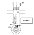
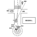
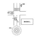
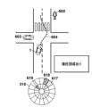
- FIG. 2 is a block diagram for explaining a functional configuration example of a control device according to the embodiment; 4A and 4B are schematic diagrams for explaining display examples of the display device according to the embodiment; 4A and 4B are schematic diagrams for explaining display examples of the display device according to the embodiment; 4A and 4B are schematic diagrams for explaining display examples of the display device according to the embodiment; 4 is a flowchart for explaining a control method according to the embodiment; 4 is a flowchart for explaining a control method according to the embodiment; Schematic diagrams for explaining various examples of a control method according to an embodiment. Schematic diagrams for explaining various examples of a control method according to an embodiment. Schematic diagrams for explaining various examples of a control method according to an embodiment. Schematic diagrams for explaining various examples of a control method according to an embodiment. Schematic diagrams for explaining various examples of a control method according to an embodiment.
- Schematic diagrams for explaining various examples of a control method according to an embodiment Schematic diagrams for explaining various examples of a control method according to an embodiment. Schematic diagrams for explaining various examples of a control method according to an embodiment. Schematic diagrams for explaining various examples of a control method according to an embodiment. Schematic diagrams for explaining various examples of a control method according to an embodiment. Schematic diagrams for explaining various examples of a control method according to an embodiment. Schematic diagrams for explaining various examples of a control method according to an embodiment. Schematic diagrams for explaining various examples of a control method according to an embodiment. Schematic diagrams for explaining various examples of a control method according to an embodiment. Schematic diagrams for explaining various examples of a control method according to an embodiment. Schematic diagrams for explaining various examples of a control method according to an embodiment. Schematic diagrams for explaining various examples of a control method according to an embodiment. Schematic diagrams for explaining various examples of a control method according to an embodiment.
- Schematic diagrams for explaining various examples of a control method according to an embodiment Schematic diagrams for explaining various examples of a control method according to an embodiment. Schematic diagrams for explaining various examples of a control method according to an embodiment. Schematic diagrams for explaining various examples of a control method according to an embodiment. 4 is a flowchart for explaining a control method according to the embodiment; Schematic diagrams for explaining various examples of a control method according to an embodiment. Schematic diagrams for explaining various examples of a control method according to an embodiment. Schematic diagrams for explaining various examples of a control method according to an embodiment. Schematic diagrams for explaining various examples of a control method according to an embodiment. Schematic diagrams for explaining various examples of a control method according to an embodiment. Schematic diagrams for explaining various examples of a control method according to an embodiment. Schematic diagrams for explaining various examples of a control method according to an embodiment. Schematic diagrams for explaining various examples of a control method according to an embodiment.
- FIG. 1 is a block diagram of a vehicle 1 according to one embodiment of the invention.
- a vehicle 1 is shown schematically in a plan view and a side view.
- the vehicle 1 is, for example, a sedan-type four-wheel passenger car.
- the vehicle 1 may be such a four-wheeled vehicle, a two-wheeled vehicle, or any other type of vehicle.
- the vehicle 1 includes a vehicle control device 2 (hereinafter simply referred to as the control device 2) that controls the vehicle 1.
- the control device 2 includes a plurality of ECUs 20 to 29 communicatively connected by an in-vehicle network.
- Each ECU includes a processor represented by a CPU, a memory such as a semiconductor memory, an interface with an external device, and the like.
- the memory stores programs executed by the processor, data used for processing by the processor, and the like.
- Each ECU may include a plurality of processors, memories, interfaces, and the like.
- the ECU 20 includes a processor 20a and a memory 20b. Processing by the ECU 20 is executed by the processor 20a executing instructions included in the program stored in the memory 20b.
- the ECU 20 may include a dedicated integrated circuit such as an ASIC for executing processing by the ECU 20 . The same applies to other ECUs.
- each ECU 20 to 29 takes charge of will be described below. Note that the number of ECUs and the functions they are in charge of can be designed as appropriate, and it is possible to subdivide or integrate them more than in the present embodiment.
- the ECU 20 executes control related to automatic driving of the vehicle 1 .
- automatic driving at least one of steering and acceleration/deceleration of the vehicle 1 is automatically controlled.
- Automatic driving by the ECU 20 includes automatic driving (also referred to as automatic driving) that does not require a driving operation by the driver of the vehicle 1 (hereinafter simply referred to as a driver), and automatic driving for assisting the driving operation by the driver.
- Automatic driving (which can also be called driving assistance) may be included.
- the ECU 21 controls the electric power steering device 3.
- the electric power steering device 3 includes a mechanism that steers the front wheels according to the driver's driving operation (steering operation) on the steering wheel 31 .
- the steering wheel 31 is an example of a steering operator.
- the electric power steering device 3 includes a motor that exerts a driving force for assisting the steering operation and automatically steering the front wheels, a sensor that detects the steering angle, and the like.
- the ECU 21 automatically controls the electric power steering device 3 in response to instructions from the ECU 20 to control the traveling direction of the vehicle 1 .
- the ECUs 22 and 23 control the detection units 41 to 43 that detect the vehicle's surroundings and process information on the detection results.
- the detection unit 41 is a camera for photographing the front of the vehicle 1 (hereinafter sometimes referred to as the camera 41), and in the case of this embodiment, is attached to the interior side of the front window in the front part of the roof of the vehicle 1. be done. By analyzing the image captured by the camera 41, it is possible to extract the outline of the target and the lane markings (white lines, etc.) on the road.
- the detection unit 42 is a lidar (Light Detection and Ranging) (hereinafter sometimes referred to as the lidar 42), and detects targets around the vehicle 1 and measures the distance to the target. .
- the lidar 42 Light Detection and Ranging
- five riders 42 are provided, one at each corner of the front of the vehicle 1, one at the center of the rear, and one at each side of the rear.
- the detection unit 43 is a millimeter wave radar (hereinafter sometimes referred to as the radar 43), detects targets around the vehicle 1, and measures the distance to the targets.
- five radars 43 are provided, one in the center of the front portion of the vehicle 1, one in each corner of the front portion, and one in each corner of the rear portion.
- the ECU 22 controls the one camera 41 and each rider 42 and processes the detection results.
- the ECU 23 performs control of the other camera 41 and each radar 43 and information processing of detection results. Equipped with two sets of devices to detect the vehicle's surroundings, the reliability of detection results can be improved. can be performed in a multifaceted manner.
- the ECU 24 controls the gyro sensor 5, the GPS sensor 24b, and the communication device 24c, and performs information processing of detection results or communication results.
- a gyro sensor 5 detects rotational motion of the vehicle 1 .
- the course of the vehicle 1 can be determined based on the detection result of the gyro sensor 5, the wheel speed, and the like.
- GPS sensor 24 b detects the current position of vehicle 1 .
- the communication device 24c performs wireless communication with a server that provides map information and traffic information, and acquires these information.
- the ECU 24 can access a database 24a of map information constructed in memory, and performs route search from the current location to the destination.
- the ECU 24, map database 24a, and GPS sensor 24b constitute a so-called navigation device.
- the ECU 25 includes a communication device 25a for inter-vehicle communication.
- the communication device 25a performs wireless communication with other vehicles in the vicinity to exchange information between the vehicles.
- the ECU 26 controls the power plant 6.
- the power plant 6 is a mechanism that outputs driving force for rotating the drive wheels of the vehicle 1, and includes, for example, an engine and a transmission.
- the ECU 26 controls the output of the engine in response to the driver's driving operation (accelerator operation or acceleration operation) detected by the operation detection sensor 7a provided on the accelerator pedal 7A, or detects the vehicle speed detected by the vehicle speed sensor 7c.
- the gear stage of the transmission is switched based on the information.
- the ECU 26 automatically controls the power plant 6 in response to instructions from the ECU 20 to control the acceleration and deceleration of the vehicle 1 .
- the ECU 27 controls lights (headlights, taillights, etc.) including the direction indicators 8 (winkers).
- the direction indicators 8 are provided at the front, door mirrors and rear of the vehicle 1 .
- the ECU 28 controls the input/output device 9.
- the input/output device 9 outputs information to the driver and receives information input from the driver.
- the voice output device 91 notifies the driver of information by voice.
- the display device 92 notifies the driver of information by displaying an image.
- the display device 92 is arranged, for example, on the surface of the driver's seat and constitutes an instrument panel or the like. Note that although audio and display are exemplified here, information may be notified by vibration or light. Information may also be notified by combining a plurality of sounds, displays, vibrations, and lights. Furthermore, depending on the level of information to be notified (for example, the degree of urgency), different combinations may be used, and different notification modes may be used.
- the input device 93 is a group of switches arranged at a position operable by the driver to give instructions to the vehicle 1, but may also include a voice input device.
- the ECU 29 controls the braking device 10 and a parking brake (not shown).
- the brake device 10 is, for example, a disc brake device, is provided on each wheel of the vehicle 1, and decelerates or stops the vehicle 1 by applying resistance to the rotation of the wheels.
- the ECU 29 controls the operation of the brake device 10 in response to the driver's driving operation (brake operation) detected by the operation detection sensor 7b provided on the brake pedal 7B, for example.
- the ECU 29 automatically controls the braking device 10 in response to instructions from the ECU 20 to control deceleration and stopping of the vehicle 1 .
- the brake device 10 and the parking brake can also be operated to keep the vehicle 1 stopped.
- the transmission of the power plant 6 is equipped with a parking lock mechanism, it can also be operated to keep the vehicle 1 in a stopped state.
- the ECU 30 controls the driver's camera 44.
- a driver camera 44 is attached at a position for photographing the driver (particularly, his face).
- the ECU 30 identifies the state of the driver by analyzing the image of the driver captured by the driver camera 44 . For example, the ECU 30 may identify the line-of-sight direction of the driver based on the orientation of the driver's face and the positions of the pupils. Further, the ECU 30 may identify whether the driver is dozing off based on whether the driver's eyes are open or the movement of the head.
- the functional blocks of the control device 2 of the vehicle 1 will be described with reference to FIG.
- the control device 2 may have multiple functional blocks shown in FIG.
- Each functional block of the control device 2 may be implemented by one or more of the ECUs 20 to 30 of the control device 2 described with reference to FIG.
- the operation of each functional block is that the CPU (for example, CPU 20a) of one or more of the ECUs 20 to 30 executes the instructions of the program stored in the corresponding memory (for example, memory 20b).
- the operation of each functional block may be implemented by dedicated circuitry such as an ASIC (Application Specific Integrated Circuit) or FPGA (Field Programmable Gate Array).
- ASIC Application Specific Integrated Circuit
- FPGA Field Programmable Gate Array
- the environment recognition unit 201 recognizes the environment around the vehicle 1 based on the detection results of the detection units 41-43.
- the surroundings of the vehicle 1 may be the detection range of the detection units 41-43.
- the environment around the vehicle 1 includes, for example, static structures and traffic participants.
- Static structures include roads (including lane markings, pedestrian crossings, road geometry, etc.) and objects permanently or semi-permanently installed on roads, such as traffic lights, signs, and the like.
- Traffic participants include vehicles other than the vehicle 1 (including four-wheeled vehicles and two-wheeled vehicles), bicycles, pedestrians, and the like. Traffic participants can be divided into moving traffic participants (e.g. moving vehicles and walking pedestrians) and stationary traffic participants (e.g. stopped vehicles, stopped vehicles, standing still). and pedestrians).
- Recognizing the surrounding environment of the vehicle 1 may include recognizing the position, size, movement direction, movement speed, and the like of the objects described above. Recognition of the surrounding environment by the environment recognition unit 201 may be performed using, for example, an existing technology, so detailed description thereof will be omitted.
- the risk identification unit 202 identifies the vehicle 1 based on the environment around the vehicle 1 recognized by the environment recognition unit 201 and the current behavior of the vehicle 1 (for example, the speed, acceleration, traveling direction, etc. of the vehicle 1). A risk factor present in the surroundings and a direction of the risk factor to the vehicle 1 are identified. The risk identification unit 202 may further identify the distance from the vehicle 1 to the risk factor.
- a risk factor is a factor that poses a risk to the vehicle 1 with a probability equal to or greater than a threshold.
- the risks to which the vehicle 1 is subjected may include the vehicle 1 coming into contact with objects present in its surroundings.
- the risk identifying unit 202 may identify the object as a risk factor when the possibility of the vehicle 1 coming into contact with an object existing around the vehicle 1 is equal to or higher than a threshold value (for example, 30% or higher).
- Vehicle 1 contacting an object may include vehicle 1 colliding with an object.
- the risk that the vehicle 1 receives may be a risk other than contact, such as the vehicle 1 entering a travel-prohibited area or falling off a cliff. In this example, no-driving areas and cliffs are risk factors.
- the risk factors may be traffic participants present around the vehicle 1. For example, when the risk identification unit 202 determines that there is a possibility that a pedestrian may run out onto the course of the vehicle 1, the risk identification unit 202 may identify this pedestrian as a risk factor.
- a risk factor may be an object placed on the road. For example, when road construction is being performed in front of the lane in which the vehicle 1 is traveling, the risk identification unit 202 identifies tools used in the road construction (for example, no entry signs, etc.) as risk factors.
- the risk identification unit 202 determines the possibility of giving a disadvantage to the vehicle 1 by using the future predicted position of an object existing around the vehicle 1 (for example, from the current time (calculated time) to 30 seconds later) and the position of the vehicle 1 It may be calculated based on future predicted positions.
- the risk identification unit 202 may determine the urgency of the risk.
- the degree of urgency of risk is an index representing how much time the vehicle 1 has to avoid the risk. For example, when an object that may come into contact with the vehicle 1 is identified as a risk factor, the urgency of the risk may be determined based on the estimated time until the vehicle 1 comes into contact with the object.
- the identification of the risk factor, its direction and distance, and the degree of urgency of the risk by the risk identification unit 202 may be performed using, for example, existing technology, so detailed description thereof will be omitted.
- the line-of-sight detection unit 203 detects the line-of-sight direction of the driver by analyzing the image obtained by the driver's camera 44 . Since detection of the line of sight by the line of sight detection unit 203 may be performed using, for example, an existing technique, detailed description thereof will be omitted.
- the avoidance action planning unit 204 uses the environment around the vehicle 1 recognized by the environment recognition unit 201, the current behavior of the vehicle 1 (for example, the speed, acceleration, traveling direction, etc. of the vehicle 1), and the risk identification unit 202 to Based on the identified risk factor and its direction and urgency, it determines the behavior that the vehicle 1 should take to avoid the risk factor. Behaviors to be taken by the vehicle 1 may include accelerating, decelerating or maintaining the speed of the vehicle 1 and placing the vehicle 1 into a particular steering state.
- the avoidance action planning unit 204 determines that the vehicle 1 should decelerate when there is a risk factor ahead of the vehicle 1 and the estimated time until the vehicle 1 comes into contact with the risk factor is long (for example, 10 seconds or more). You may decide to be The avoidance action planning unit 204 decelerates the vehicle 1 when there is a risk factor diagonally left ahead of the vehicle 1 and the predicted time until the vehicle 1 comes into contact with the risk factor is short (for example, 5 seconds or less). It may decide that it should turn right. The avoidance action planner 204 may determine that the vehicle 1 should remain straight when there are risk factors on both sides of the vehicle 1 (eg, between walls and cliffs). Determination of the behavior by the avoidance action planning unit 204 may be performed using, for example, existing technology, so detailed description thereof will be omitted.
- the braking control unit 205 controls braking of the vehicle 1. For example, when the avoidance action planning unit 204 determines that the vehicle 1 should be decelerated, the braking control unit 205 automatically (that is, even if the brake pedal 7B is not operated) brakes the vehicle. By braking 1 the vehicle 1 may be slowed down or even stopped.
- the steering guidance unit 206 performs a steering guidance operation using the steering operator of the vehicle 1 .
- the steering guidance operation is an operation for guiding the driver to operate the steering operation element so as to avoid risk factors.
- the steering wheel 31 in FIG. 1 will be described below as an example of the steering operator of the vehicle 1 .
- the avoidance action planning unit 204 determines that the vehicle 1 should turn right.
- the steering guidance section 206 may perform the following operations.
- the steering guidance unit 206 prompts the driver to turn the steering wheel 31 to the right by vibrating a specific portion on the right side of the steering wheel 31 for a predetermined time (for example, 1 second or 3 seconds).
- a predetermined time for example, 1 second or 3 seconds.
- the steering guidance unit 206 may perform this vibration only once, may perform this vibration a plurality of times (for example, three times) at predetermined intervals (for example, 5 seconds), or repeat until the risk factor is eliminated.
- the steering guidance unit 206 may prompt the driver to rotate the steering wheel 31 to the right by applying force to the steering wheel 31 in the direction of rotation (right rotation in this example).
- the rotational force may be a force that rotates the steering wheel 31 by a predetermined amount (eg, 1 degree, 5 degrees, 10 degrees, etc.) when the steering wheel 31 is not held by the driver.
- a predetermined amount eg, 1 degree, 5 degrees, 10 degrees, etc.
- the steering wheel 31 may or may not actually rotate.
- the driver receives a hitting feeling from the steering wheel 31 in a specific rotational direction.
- the steering guide unit 206 may apply a force in the reverse rotational direction to the steering wheel 31 so as to reverse the rotation. , it is not necessary to apply such force in the reverse rotation direction.
- the steering guidance unit 206 may apply the force in the rotational direction to the steering wheel 31 only once, or may apply the force a plurality of times (eg, three times) at predetermined intervals (eg, 5 seconds). may be repeated until the risk factor is eliminated.
- the steering guidance unit 206 may reduce the torque for rotating the steering wheel 31 in the right direction, thereby making it easier for the driver to rotate the steering wheel 31 in the right direction.
- the steering guidance unit 206 may use a combination of some or all of these operations as the steering guidance operation.
- the avoidance action planning section 204 determines that the vehicle 1 should turn to the left, the steering guidance section 206 may perform the above operation in the opposite direction.
- the steering guidance section 206 may increase the torque for rotating the steering wheel 31 .
- the steering guidance unit 206 rotates the steering wheel 31 to the left in order to guide the driver so that the steering state of the vehicle 1 permits only straight traveling and turning to the right, but does not permit turning to the left. You may increase only the torque for.
- the notification determination unit 207 determines whether or not to notify the driver of the information, and determines the content and method of notification when the information is to be notified. For example, the notification determination unit 207 may determine to notify the driver of the direction of the risk factor when the risk factor exists around the vehicle 1 . The notification determination unit 207 may also determine to notify the driver of the distance from the vehicle 1 to the risk factor. Furthermore, the notification determination unit 207 may determine to notify the traveling direction of the vehicle 1 for avoiding risk factors. Details of the information notified to the driver will be described later.
- the output control unit 208 controls the operation of devices for notifying information to the driver, specifically the audio output device 91 and the display device 92 described above. For example, the output control unit 208 outputs information determined to be notified by the notification determination unit 207 to the driver through the audio output device 91 and/or the display device 92 .
- a display device 92 for displaying information to the driver will be described with reference to FIGS. 3A to 3C.
- the display device 92 can display information indicating the direction with respect to the vehicle 1 .
- the display device 92 may be able to display information indicating the distance from the vehicle 1 .
- Display device 92 may be any display device capable of displaying such information.
- the display device 92 may be a dot-matrix display attached to the instrument panel of the vehicle 1 .
- the display device 92 may be a set of a plurality of light-emitting portions capable of emitting light in a specific shape.
- the display device 92 may be a head-up display.
- the display device 92 may have a circular display area 300 as shown in FIG. 3A to indicate the direction with respect to the vehicle 1 .
- Display area 300 occupies a portion of display device 92 .
- the display device 92 can display a fan-shaped indicator at any position within the display area 300 .
- the display area 300 is displayed in a base color (for example, white or black) when no indicator is displayed.
- the indicator is displayed so as to be distinguishable from the portion of the display area 300 other than the indicator.
- the indicator is displayed in a color (eg, red or blue) different from the base color, and the portion other than the indicator is displayed in the base color.
- the indicators may be displayed by flashing certain portions.
- the indicator in the display area 300 indicates the direction with respect to the vehicle 1.
- the position of the indicator with respect to the center of the display area 300 and the direction with respect to the vehicle 1 may be associated.
- the upward direction in the drawing corresponds to the front of the vehicle 1
- the downward direction in the drawing corresponds to the rear of the vehicle 1
- the rightward direction in the drawing corresponds to the right side of the vehicle 1
- the leftward direction in the drawing corresponds to the left side of the vehicle 1.
- FIG. 3A shows an indicator 301 as an example of an indicator.
- Indicator 301 may be displayed in red, for example.
- the indicator 301 indicates the oblique left front of the vehicle 1 .
- the display device 92 may display all indicators in the same color, or may display each indicator in a color selected from a plurality of colors. Further, the display device 92 may display all indicators with the same degree of emphasis, or may display each indicator with a degree of emphasis selected from a plurality of degrees of emphasis.
- the degree of emphasis is an index representing the ease of attracting the driver's attention. The higher the degree of emphasis, the easier it is to attract the driver's attention.
- the display device 92 may display the indicators with different densities or brightness. The higher the density or brightness, the higher the enhancement. For example, a dark red color is more likely to attract the driver's attention than a light red color.
- the display device 92 may display the indicators differently. For example, the display device 92 may flash the indicator to increase the emphasis of the indicator.
- the display device 92 may have a circular display area 310 as shown in FIG. 3B to indicate the direction to and distance from the vehicle 1 . Differences between the display area 300 and the display area 310 will be mainly described below.
- the display area 310 is divided into 16 sectors along the entire circumference (that is, 360 degrees), and each sector is divided into two, one closer to the center and one farther from the center. Therefore, the display area 310 has 32 areas with different directions and distances from the center.
- Display device 92 displays indicators using one or more of the 32 areas of display area 310 .
- the indicators in the display area 310 indicate the direction with respect to the vehicle 1 .
- the position of the indicator with respect to the center of the display area 310 and the direction with respect to the vehicle 1 may be associated.
- indicators in the display area 310 show the distance from the vehicle 1 .
- the distance (close or far) of the indicator from the center of the display area 310 may be associated with the distance from the vehicle 1 .
- the distance from the vehicle 1 is shown in two steps, but it may be shown in three steps or more.
- FIG. 3B shows indicators 311 and 312 as examples of indicators.
- the indicator 311 indicates a distant position obliquely forward right of the vehicle 1 .
- Indicator 311 may be displayed in dark red, for example.
- the indicator 312 indicates a near position on the front left side of the vehicle 1 .
- Indicator 312 may be displayed in light red, for example.
- the emphasis of indicator 311 is higher than the emphasis of indicator 312 .
- the display device 92 may include an LED (light emitting diode) string 320 as shown in FIG. 3C to indicate the direction relative to the vehicle 1 .
- the LED string 320 may consist of a plurality of LEDs arranged in a line.
- the display device 92 can light a selected portion of the LED row 320, and the lighted portion serves as an indicator.
- the LED row 320 is installed below the windshield of the vehicle 1 .
- the indicator of the LED string 320 and the direction with respect to the vehicle 1 may correspond to each other. For example, a line segment starting from the driver's head and passing through the indicator may indicate the direction with respect to the vehicle 1 .
- FIG. 3C shows an indicator 321 as an example of an indicator.
- the indicator 321 indicates the oblique left front of the vehicle 1 .
- the direction relative to the vehicle 1 is indicated by the position of the indicator.
- the direction relative to vehicle 1 may be indicated by other methods.
- the directions for the vehicle 1 may be indicated by words such as “forward” and “diagonally forward to the right", or may be indicated by symbols such as arrows.
- the distance from the vehicle 1 is indicated by the position of the indicator.
- the distance from vehicle 1 may be indicated by other methods.
- the distance from the vehicle 1 may be indicated by Arabic numerals or indicated by the distance between two points (for example, the distance between the tip and the rear end of an arrow).
- FIGS. 4A and 4B A control method by the control device 2 related to the present disclosure will be described with reference to FIGS. 4A and 4B.
- This operation may be started when the power of the vehicle 1 is turned on, or may be started in response to an instruction from the driver to start this operation.
- Each step of the method of FIGS. 4A and 4B may be performed by the functional blocks of FIG.
- the steps of the methods of FIGS. 4A and 4B may be performed by a processor executing a program stored in memory.
- at least some steps of the methods of FIGS. 4A and 4B may be performed by dedicated circuitry.
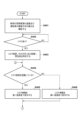
- step S401 the control device 2 (specifically, the environment recognition unit 201 and the line-of-sight detection unit 203) starts recognizing the surrounding environment of the vehicle 1 and detecting the line-of-sight direction of the driver. Recognition of the surrounding environment of the vehicle 1 and detection of the driver's gaze direction are continuously performed through the methods of FIGS. 4A and 4B.
- the environment recognition unit 201 may recognize the surrounding environment of the vehicle 1 at a predetermined cycle (for example, a cycle of 10 milliseconds to 100 milliseconds).
- the environment recognition unit 201 may store the recognition result in a storage device (eg, memory within the ECU) for a predetermined period (eg, 1 minute) for subsequent processing.
- the line-of-sight detection unit 203 may detect the line of sight of the driver at a predetermined cycle (for example, a cycle of 10 milliseconds).
- the line-of-sight detection unit 203 may store the detection result in a storage device (for example, memory in the ECU) for a predetermined period (for example, 1 minute) for subsequent processing.
- step S402 the control device 2 (specifically, the risk identification unit 202) determines whether or not there is a risk around the vehicle 1. If it is determined that there is a risk ("YES” in step S402), the control device 2 shifts the process to step S403, otherwise ("NO” in step S402), repeats step S402.
- the control device 2 identifies the risk factor that causes the risk identified in step S402, the direction of the risk factor to the vehicle 1, and the degree of urgency of the risk. .
- the control device 2 may or may not identify the distance from the vehicle 1 to the risk factor. Determining the direction (and possibly distance) of the risk factor and determining the urgency of the risk continues until it is determined that the risk has been eliminated.
- the risk identification unit 202 may identify the direction (and possibly the distance) of the risk factor and the degree of urgency of the risk at predetermined intervals (for example, 10 millisecond intervals).
- step S404 the control device 2 (specifically, the notification determination unit 207) determines whether the driver recognizes the risk factor identified in step S403. When it is determined that the driver recognizes the risk factor ("YES" in step S404), the control device 2 shifts the process to step S405, otherwise ("NO" in step S404). Then, the process transitions to step S406.
- the notification determination unit 207 may determine whether the driver recognizes the risk factor based on the driver's line of sight. For example, the notification determining unit 207 determines whether the line of sight of the driver is directed toward the risk factor (for example, the risk factor is included within a predetermined range from the center of the line of sight), or the most recent (for example, one minute It may be determined that the driver is aware of the risk factor when the driver faces the risk factor within ). The notification determining unit 207 may determine whether the driver recognizes the risk factor based on factors other than the driver's line of sight. For example, the notification determining unit 207 may determine that the driver recognizes the risk factor when the driver steers the vehicle 1 away from the risk factor.
- step S405 the control device 2 (specifically, the output control unit 208) displays the risk information on the display device 92 with a low degree of emphasis
- step S406 the control device 2 (specifically, the output control unit 208) displays the risk information on the display device 92 with a high degree of emphasis.
- the output control unit 208 displays the risk information on the display device 92 with a high degree of emphasis so that the driver does not recognize the risk factor.
- risk information is displayed on the display device 92 with a low degree of emphasis.
- a low degree of emphasis in step S405 means that the degree of emphasis in step S406 is lower than that in step S406.
- Risk information is information about the risk factors identified in step S403.
- risk information includes the direction of risk factors for vehicle 1 .
- Risk information may further include the distance from the vehicle 1 to the risk factor.
- Risk information, including direction of risk factors may be displayed using the indicators of FIGS. 3A-3C, for example.
- Risk information, including the direction of the risk factor and the distance to the risk factor may be displayed using the indicator of FIG. 3B, for example.
- the display of risk information continues until terminated in a step to be described later. By displaying the risk information, the driver's attention can be drawn in the direction of the risk, and the driver can easily recognize the risk.
- steps S404 to S406 described above are repeated while there is a risk factor and no steering guidance operation is performed. Therefore, the output control unit 208 maintains the display of the risk information while the risk factor exists and the steering guidance operation is not performed.
- the output control unit 208 executes step S405. , to display the risk information with a lower emphasis, ie to reduce the emphasis of the risk information.
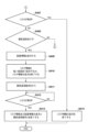
- the control device 2 determines whether the risk identified at step S402 has been eliminated. If the control device 2 determines that the risk has been eliminated ("YES” in step S407), the process proceeds to step S414. Otherwise (“NO” in step S407), the process proceeds to step S408. Transition to The risk may be resolved by the behavior of the vehicle 1 (eg route change or speed change) or by the behavior of the risk factor (eg route change or speed change of other traffic participants). The behavior of the vehicle 1 may be based on the driver's operation or may be based on the operation of the braking control unit 205 .
- control device 2 (specifically, the output control unit 208) terminates the display of risk information on the display device 92 in step S414.
- step S408 the control device 2 (specifically, the notification determination unit 207) determines whether or not to perform a steering guidance operation using the steering operator based on the urgency of the risk.
- the control device 2 shifts the process to step S409; Transition to S404.
- the notification determination unit 207 determines that the steering operation is to be performed using the steering operator when the risk is highly urgent and the vehicle 1 needs to be steered to avoid the risk factor. may
- the control device 2 displays the avoidance information on the display device 92.
- the avoidance information is information indicating the traveling direction of the vehicle 1 for avoiding risk factors. For example, when the risk factor exists on the left side of the vehicle 1 , the avoidance information may indicate the diagonal right front of the vehicle 1 . Avoidance information including the direction of travel of the vehicle 1 may be displayed using, for example, the indicators of FIGS. 3A-3C.
- the output control unit 208 may display the avoidance information in a color different from the color used to display the risk information, or may display the avoidance information and the risk information in the same color. For example, the output control unit 208 may display risk information in red and avoidance information in blue. By displaying the avoidance information, it becomes easier for the driver to recognize in which direction the vehicle 1 should be steered, and the safety of the vehicle 1 is improved.
- step S410 the control device 2 (specifically, the output control unit 208) displays the risk information on the display device 92 with a low degree of emphasis, or terminates the display of the risk information.
- a low degree of emphasis in step S410 means that the degree of emphasis in step S406 is low.
- Drivers tend to turn the steering wheel in the direction of their attention in an emergency.
- the driver's attention is likely to be attracted to the avoidance information. Therefore, the effectiveness of the steering guidance operation using the steering operator is improved.
- the control device 2 (specifically, the steering guidance unit 206) performs a steering guidance operation.
- the steering guidance operation may be performed only once until the risk is eliminated, or may be performed continuously or intermittently until the risk is eliminated.
- Steps S409-S411 may be performed in any order, or may be performed substantially simultaneously.
- the output control unit 208 may set the emphasis of the avoidance information displayed in step S409 higher than the emphasis of the risk information displayed in step S410. For example, the output control unit 208 may display avoidance information in dark blue in step S409 and risk information in light red in step S410.
- step S412 the control device 2 (specifically, the risk identification unit 202) determines whether the risk identified at step S402 has been eliminated. If it is determined that the risk has been eliminated ("YES" in step S412), the control device 2 shifts the process to step S413, otherwise ("NO” in step S412), repeats step S412. .
- the determination in step S412 may be the same as the determination in step S407.
- the control device 2 (specifically, the output control unit 208) ends the display of the avoidance information on the display device 92 in step S413.
- the control device 2 (specifically, the output control unit 208) ends the display of the risk information.
- the control device 2 (specifically, the steering guidance unit 206) ends the guidance avoidance action when the guidance avoidance action is being performed continuously or intermittently.
- risk information is displayed with a low degree of emphasis when the driver is aware of risk factors.
- the risk information may be given the same degree of emphasis (for example, a higher degree of emphasis than the risk information in step S410) whether the driver recognizes the risk factor or not. may be displayed.
- the line-of-sight direction detection in step S404 and steps S404 and S405 may be omitted.
- risk information is displayed with a low degree of emphasis when the driver is aware of risk factors.
- risk information may not be displayed when the driver is aware of risk factors.
- risk information is displayed with two levels of emphasis.
- the risk information may be displayed with one level of emphasis.
- the risk information may be displayed with the same degree of emphasis whether the driver recognizes the risk factor or not, and the display of the risk information may end at step S410.
- the risk information is displayed when the driver is unaware of the risk factor, and the risk information is displayed both when the driver is aware of the risk factor and when the steering guidance action is performed. It does not have to be displayed.
- FIGS. 4A and 4B Various specific examples of the control method of FIGS. 4A and 4B will be described with reference to FIGS. 5A-9B.
- the technology of the present disclosure may be applied when traveling in a country that has right-hand traffic regulations.
- the control device 2 uses the display device 92 of FIG. 3A to display risk information with one level of emphasis.
- the controller 2 does not specify the distance to the risk factor, so the risk information does not include the distance to the risk factor.
- the control device 2 displays risk information and avoidance information in different colors.
- the control device 2 displays the risk information regardless of whether the driver recognizes the risk factor.
- the control device 2 does not display the risk information when executing the steering guidance operation.
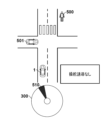
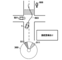
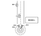
- FIG. 5A it is assumed that vehicle 1 is running in front of an intersection. Assume that a pedestrian 500 is walking at the back of an intersection and a vehicle 501 is about to enter the intersection. Since pedestrian 500 is walking straight, controller 2 does not identify pedestrian 500 as a risk factor. On the other hand, the control device 2 identifies the vehicle 501 as a risk factor because the vehicle 501 is about to enter the intersection. Therefore, the control device 2 displays the indicator 510 in red in the display area 300 as risk information. Indicator 510 indicates the diagonally left front of vehicle 1 . After that, as shown in FIG. 5B , when the vehicle 1 stops and the risk of the vehicle 1 contacting the vehicle 501 disappears, the control device 2 ends the display of the indicator 510 .
- the control device 2 performs a steering guidance operation so that the vehicle 1 moves along the route 503 (that is, the steering wheel 31 is rotated to the right and then to the left). Further, the control device 2 displays the indicator 511 in blue in the display area 300 as avoidance information.
- the indicator 511 indicates the direction in which the vehicle 1 should travel, that is, the diagonally forward right direction. Further, control device 2 terminates the display of indicator 510 .
- the control device 2 moves the position of the indicator 511 in the direction of the arrow 504 in accordance with the change in the direction in which the vehicle 1 should travel as the vehicle 1 moves along the route 503 .
- the control device 2 uses the display device 92 of FIG. 3A to display risk information with two levels of emphasis.
- the controller 2 does not specify the distance to the risk factor, so the risk information does not include the distance to the risk factor.
- the control device 2 displays risk information and avoidance information in different colors.
- the control device 2 displays the risk information regardless of whether the driver recognizes the risk factor.
- the control device 2 displays the risk information with a low degree of emphasis when executing the steering guidance operation.
- the control device 2 displays the risk information on the indicator 510 with a high degree of emphasis (eg dark red).
- a high degree of emphasis eg dark red
- the control device 2 displays the indicator 511 with a high emphasis (for example, dark blue) and displays the indicator 511 with a low emphasis (for example, light red).
- 512 is displayed.
- Indicator 511 indicates avoidance information and indicator 512 indicates risk information.
- the degree of emphasis of indicator 511 is higher than the degree of emphasis of indicator 512 .
- the control device 2 uses the display device 92 of FIG. 3B to display risk information with two levels of emphasis.
- the controller 2 identifies the distance to the risk factor and the risk information includes the distance to the risk factor.
- the control device 2 displays risk information and avoidance information in different colors.
- the control device 2 changes the degree of emphasizing the risk information depending on whether the driver recognizes the risk factor.
- the control device 2 displays the risk information with a low degree of emphasis when executing the steering guidance operation.
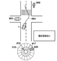
- control device 2 identifies pedestrian 600 as a risk factor because pedestrian 600 is walking toward the crosswalk. Pedestrian 600 is out of line-of-sight 601 of the driver. Therefore, the control device 2 displays the indicator 611 in the display area 310 with a high degree of emphasis (for example, dark red) as risk information. Indicator 611 indicates a distant position obliquely forward right of vehicle 1 where pedestrian 600 is located. Furthermore, the control device 2 displays the indicator 610 indicating the current traveling direction of the vehicle 1 with a low degree of emphasis (for example, light blue).
- a high degree of emphasis for example, dark red
- the control device 2 Since it is not necessary to draw the driver's attention to the current direction of travel of the vehicle 1, the control device 2 makes the indicator 610 less emphasized. Since indicator 610 does not need to show information about distance, indicator 610 uses two areas within the same sector of display area 310 .
- the control device 2 terminates the display of the indicator 611 and displays the indicator 612 in the display area 310 with a low degree of emphasis (for example, light red) as risk information. In other words, the control device 2 reduces the emphasis of risk information. Control device 2 continues to display indicator 610 .
- Control device 2 identifies vehicle 603 as a risk factor. Since the vehicle 603 is not in the line-of-sight direction 602 of the driver, the control device 2 displays the indicator 611 in the display area 310 with a high degree of emphasis (for example, dark red) as risk information. The indicator 613 indicates a position near the left oblique front of the vehicle 1 where the vehicle 603 is located. After that, as shown in FIG. 6C , when the vehicle 1 stops and the risk of the vehicle 1 contacting the pedestrian 600 and the vehicle 603 disappears, the control device 2 ends the display of the indicators 612 and 613 . Further, since the vehicle 1 is stopped, the control device 2 also ends the display of the indicator 610 indicating the traveling direction of the vehicle 1 .
- a high degree of emphasis for example, dark red
- the control device 2 turns the indicator 610 Instead, the indicator 614 is displayed in light blue. Indicator 614 indicates the direction of travel of vehicle 1 to avoid the risk factor (vehicle 603 in this example). Since the degree of urgency is not high and the steering operation is not performed using the steering operator, the control device 2 sets the indicator 614 to a low emphasis.
- the controller 2 directs the vehicle 1 to move along the path 604 (i.e., the steering wheel 31 A steering operation is performed by using the steering operation element so that the steering wheel is rotated to the right and then to the left.
- the control device 2 displays the indicator 617 in dark blue in the display area 310 as avoidance information.
- the indicator 617 indicates the direction in which the vehicle 1 should travel, that is, diagonally forward right. Indicator 617 does not need to show information about distance, so indicator 617 uses two areas within the same sector of display area 310 .
- the control device 2 terminates the display of the indicator 616, and instead displays the indicator 619 in the display area 310 with a low emphasis (for example, light red) as risk information.
- the indicator 619 indicates a near position diagonally left front of the vehicle 1 where the vehicle 603 is located.
- the control device 2 gives priority to the indicator 617, shifts the position of the indicator 615, and uses the indicator 618 to display the risk information of the pedestrian 600. indicates Indicator 618 is displayed with a low emphasis (eg, light red).
- control device 2 moves the position of the indicator 618 according to the change in the direction in which the vehicle 1 should travel as the vehicle 1 moves along the route 604 .
- control device 2 may display indicator 620 instead of indicator 618 .
- the direction of shifting the position of the indicator 615 is different from that in FIG. 7A.
- the control device 2 shifts the indicator 617 in a direction away from the route 604 of the vehicle 1 for avoiding the risk factor and displays it as an indicator 620 .
- Indicator 620 like indicator 618, is displayed with a low emphasis (eg, light red). This display makes it easier for the driver to steer to the left away from the direction indicated by indicator 620 after steering to the right according to indicator 617 . As a result, it becomes easier to guide the driver to drive along the route 604 .
- the above-described third embodiment will be described using another situation.
- the vehicle 1 is traveling on a road as shown in FIG. 8A.
- a vehicle 801 is stopped in front of the vehicle 1 .
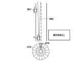
- the control device 2 does not recognize the vehicle 801 at this point. Therefore, the control device 2 displays only the indicator 810 indicating the traveling direction of the vehicle 1 in the display area 310 with a low degree of emphasis (for example, light blue).
- the line-of-sight direction 802 of the driver faces forward.
- the control device 2 recognizes the vehicle 801 .
- the control device 2 identifies the vehicle 801 as a risk factor because the vehicle 801 runs off into the lane.
- the vehicle 801 is out of the driver's line of sight 802 . Therefore, the control device 2 displays the indicator 811 in the display area 310 with a high degree of emphasis (for example, dark red) as risk information.
- the indicator 811 indicates a distant position obliquely forward left of the vehicle 1 where the vehicle 801 is located. Control device 2 continues to display indicator 810 .
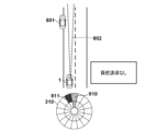
- the control device 2 terminates the display of the indicator 811 and displays the indicator 812 in the display area 310 with a low degree of emphasis (for example, light red) as risk information. In other words, the control device 2 reduces the emphasis of risk information. Control device 2 continues to display indicator 810 .
- the control device 2 uses the indicator 813 instead of the indicator 810. Display in light blue.
- the indicator 813 indicates the direction of travel of the vehicle 1 to avoid the risk factor (the vehicle 801 in this example). Since the degree of urgency is not high and the steering operation is not performed using the steering operator, the control device 2 sets the indicator 813 to a low emphasis.
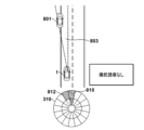
- a steering guidance operation is performed using a steering operation member so as to rotate the wheel 31 in the right direction.
- the control device 2 displays the indicator 814 in dark blue in the display area 310 as avoidance information.
- the indicator 814 indicates the direction in which the vehicle 1 should travel, that is, diagonally forward right. Indicator 814 does not need to show information about distance, so indicator 814 uses two areas within the same sector of display area 310 . Control device 2 continues to display indicator 812 with a low emphasis.
- the control device 2 uses the steering control to direct the vehicle 1 to go straight (that is, to prevent the driver from turning the steering wheel 31), as shown in FIG. 9B. to perform the steering guidance operation.
- the control device 2 displays the indicator 815 in dark blue instead of the indicator 814 in the display area 310 as the avoidance information.
- vision can receive the most information among human senses. Therefore, it is effective to use a display device to inform the driver that there is a risk around the vehicle. However, if the driver does not see the information displayed on the display device, this information cannot inform the driver of the existence of the risk.
- the following embodiments make it possible to adequately inform the driver of the presence of risk.
- the risk identification unit 202 uses the environment around the vehicle 1 recognized by the environment recognition unit 201 and the current behavior of the vehicle 1 (for example, the speed, acceleration, direction of travel, etc. of the vehicle 1). Based on this, it is identified that there is a risk factor around the vehicle 1 .
- the risk identification unit 202 may further identify the direction of the risk factor with respect to the vehicle 1 and the distance from the vehicle 1 to the risk factor.
- a risk factor is a factor that poses a risk to the vehicle 1 with a probability equal to or greater than a threshold.
- the risks to which the vehicle 1 is subjected may include the vehicle 1 coming into contact with objects present in its surroundings.
- the risk identifying unit 202 may identify the object as a risk factor when the possibility of the vehicle 1 coming into contact with an object existing around the vehicle 1 is equal to or higher than a threshold value (for example, 30% or higher).
- Vehicle 1 contacting an object may include vehicle 1 colliding with an object.
- the risk that the vehicle 1 receives may be a risk other than contact, such as the vehicle 1 entering a travel-prohibited area or deviating from the track.
- the no-drive area is a risk factor.
- the notification determination unit 207 determines whether or not to notify the driver of information, and determines the content and manner of notification when the information is to be notified. For example, the notification determination unit 207 may determine to notify the driver of the existence of the risk factor when the risk factor exists around the vehicle 1 . The notification determination unit 207 may also determine to notify the driver of the direction of the risk factor to the vehicle 1, the distance from the vehicle 1 to the risk factor, or both. Details of the information notified to the driver will be described later.
- the output control unit 208 controls the operation of devices for notifying information to the driver, specifically the audio output device 91 and the display device 92 described above. For example, the output control unit 208 outputs information determined to be notified by the notification determination unit 207 to the driver through the audio output device 91 and/or the display device 92 . If the steering element of the vehicle 1, for example, the steering wheel 31 has a notification function, the output control unit 208 may control the operation of the steering wheel 31 so as to notify the driver of the information. For example, if the steering wheel 31 can vibrate, the output control unit 208 may notify the information by vibrating the steering wheel 31 .
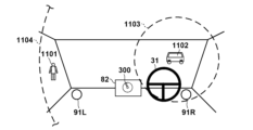
- the display device 92 can display information indicating that a specific event has occurred. Moreover, the display device 92 may be capable of displaying information indicating the direction with respect to the vehicle 1 . In FIG. 3A, an indicator may be displayed in display area 300 to indicate that a particular event has occurred (eg, the presence of a risk factor around vehicle 1).
- a control method by the control device 2 related to the present disclosure will be described with reference to FIG.
- This operation may be started when the power of the vehicle 1 is turned on, or may be started in response to an instruction from the driver to start this operation.
- Each step of the method of FIG. 10 may be performed by the functional blocks of FIG. As such, each step of the method of FIG. 10 may be performed by a processor executing a program stored in memory. Alternatively or additionally, at least some steps of the method of FIG. 10 may be performed by dedicated circuitry.
- step S1001 the control device 2 (specifically, the environment recognition unit 201 and the line-of-sight detection unit 203) starts recognizing the surrounding environment of the vehicle 1 and detecting the line-of-sight direction of the driver. Recognition of the surrounding environment of the vehicle 1 and detection of the line-of-sight direction of the driver are continuously performed through the method of FIG.
- the environment recognition unit 201 may recognize the surrounding environment of the vehicle 1 at a predetermined cycle (for example, a cycle of 10 milliseconds to 100 milliseconds).
- the environment recognition unit 201 may store the recognition result in a storage device (eg, memory within the ECU) for a predetermined period (eg, 1 minute) for subsequent processing.
- the line-of-sight detection unit 203 may detect the line of sight of the driver at a predetermined cycle (for example, a cycle of 10 milliseconds).
- the line-of-sight detection unit 203 may store the detection result in a storage device (for example, memory in the ECU) for a predetermined period (for example, 1 minute) for subsequent processing.
- step S1002 the control device 2 (specifically, the risk identification unit 202) determines whether or not there is a risk around the vehicle 1. If it is determined that there is a risk ("YES” in step S1002), the control device 2 shifts the process to step S1003, otherwise ("NO” in step S1002), repeats step S1002.
- the control device 2 (specifically, the risk identification unit 202) identifies risk factors that cause the risk identified in step S1002.
- the control device 2 may or may not identify the direction of the risk factor with respect to the vehicle 1 and the distance from the vehicle 1 to the risk factor. Identification of the direction and distance of risk factors continues until it is determined that the risk has been eliminated.
- the risk identification unit 202 may identify the direction and distance of the risk factor at a predetermined cycle (for example, 10 millisecond cycle).
- step S1004 the control device 2 (specifically, the notification determination unit 207) determines whether the driver recognizes the risk factor identified in step S1003. When it is determined that the driver recognizes the risk factor ("YES" in step S1004), the control device 2 shifts the process to step S1010, otherwise ("NO" in step S1004). Then, the process transitions to step S1005.
- the notification determination unit 207 may determine whether the driver recognizes the risk factor based on the driver's line of sight. For example, the notification determining unit 207 determines whether the line of sight of the driver is directed toward the risk factor (for example, the risk factor is included within a predetermined range from the center of the line of sight), or the most recent (for example, within 1 minute) It may be determined that the driver recognizes the risk factor when the driver is facing the risk factor in the direction of the driver.
- the range of the driver's line of sight used to determine whether the driver is aware of the risk factor may be the range where the driver is considered to be gazing (hereinafter referred to as the gazing range). .
- the gaze range of the driver may be a predetermined range (for example, within 15 degrees from the center) from the center of the line of sight of the driver.
- the driver's gaze range may be a range narrower than the driver's field of view.
- the notification determining unit 207 may determine whether the driver recognizes the risk factor based on factors other than the driver's gaze direction. For example, the notification determining unit 207 may determine that the driver recognizes the risk factor when the driver steers the vehicle 1 away from the risk factor.
- step S1005 the control device 2 (specifically, the notification determination unit 207) determines whether the driver can visually recognize the display position of the risk information. If it is determined that the driver can visually recognize the display position of the risk information ("YES" in step S1005), the control device 2 shifts the process to step S1007; NO"), the process proceeds to step S1006.
- “Risk information” is information about the risk factors identified in step S1003.
- the risk information indicates that there are risk factors around the vehicle 1 .
- the risk information may also include the direction of the risk factor relative to the vehicle 1, the distance from the vehicle 1 to the risk factor, or both.
- the presence of risk factors in the surroundings of the vehicle 1 may be indicated, for example, by displaying the indicators of FIGS. 3A-3C.
- the direction of risk factors may be displayed using the indicators of FIGS. 3A-3C, for example.
- the distance to the risk factor may be displayed using the indicator of FIG. 3B, for example.
- the display of risk information continues until terminated in a step to be described later. By displaying the risk information, the driver's attention can be drawn in the direction of the risk, and the driver can easily recognize the risk.
- the display position of risk information is the position where the risk information is displayed on the display device 92.
- the display area 300 is the display position of the risk information.
- the display area 310 is the display position of the risk information.
- the LED row 320 is the display position of the risk information.
- the notification determination unit 207 may determine whether the driver can visually recognize the display position of the risk information based on the driver's line of sight. For example, the notification determination unit 207 estimates the visual field of the driver, and determines whether the driver can visually recognize the display position of the risk information based on whether the display position of the risk information is included in the estimated position of the driver. You can judge whether The driver's field of view may be estimated to be within a predetermined range from the center of the driver's line of sight (eg, within 80 degrees from the center).
- the notification determining unit 207 may determine whether the driver can visually recognize the display position of the risk information based on factors other than the driver's visual field. For example, the notification determination unit 207 may determine that the driver cannot visually recognize the display position of the risk information when the driver has his/her eyes closed.
- step S1006 the control device 2 (specifically, the output control unit 208) informs the driver that there is a risk factor around the vehicle 1 in a manner different from the display of the risk information at the display position of the risk information. to notify. Notification in a form different from the display of risk information at the display position of risk information is hereinafter referred to as auxiliary notification.
- Auxiliary notification may be made in a manner recognizable by senses other than sight.
- the auxiliary notification may be provided in an audibly perceptible manner.
- the output control unit 208 may output audible information indicating that a risk factor exists around the vehicle 1 .
- this audible information may be a warning sound of a predetermined pitch (e.g., a "beep, beep" sound) or a voice message conveying a message (e.g., "Be careful around your vehicle”). voice).
- supplementary notification with audible information may indicate the direction of risk factors.
- the output control unit 208 may indicate the direction of risk factors by adjusting the volume of audible information in each speaker. For example, when the vehicle 1 has speakers in the diagonally forward right and the diagonally forward left in the vehicle interior, the output control unit 208 outputs the audible information only from the diagonally forward right speaker so that the risk factor exists on the right side. By outputting audible information only from the front left speaker, it is indicated that the risk factor exists on the left side, and by outputting audible information only from the speakers on both sides, it is indicated that the risk factor exists in the direction of travel. may be indicated.
- the output control unit 208 may indicate the direction of risk factors by adjusting the sound quality of the audible information. For example, the output control unit 208 may indicate that there is a risk factor ahead of the vehicle 1 with high-pitched audible information, and indicate that there is a risk factor ahead of the vehicle 1 with low-pitched audible information. Alternatively or in addition to this, the output control unit 208 indicates the presence of the risk factor ahead of the vehicle 1 with audible information of the integer order harmonics, and non-indicates the presence of the risk factor ahead of the vehicle 1 . It may be indicated by audible information of integer order overtones.
- the output control unit 208 may indicate the direction of the risk factor by the content of the message (for example, "Beware of the diagonal left front of the vehicle").
- Auxiliary notification may be made in a tactile and recognizable manner.
- the output control unit 208 may indicate the presence of a risk factor in the surroundings by vibrating the steering controls (eg, the steering wheel 31) of the vehicle 1.
- FIG. This vibration may be intermittent or continuous.
- a vibrating auxiliary notification may indicate the direction of the risk factor.
- the output control unit 208 indicates that the risk factor exists on the right side by vibrating only the right side of the steering wheel, and indicates that the risk factor exists on the left side by vibrating only the left side of the steering wheel. and may indicate the presence of a risk factor in the direction of travel by vibrating both sides of the steering control.
- Auxiliary notification may be made using vision.
- the vehicle 1 may have an auxiliary display device such as an LED on the side of the passenger compartment, and the control device 2 may perform auxiliary notification by lighting or blinking the auxiliary display device. Even if the driver is looking at the side of the vehicle 1 and cannot see the display device in front of the passenger compartment, the display device on the side of the passenger compartment can be visually recognized in some cases.
- auxiliary notification By performing the auxiliary notification as described above, even if the driver cannot visually recognize the display position of the risk information, it is possible to inform the driver that there are risk factors around the vehicle 1. In addition, by not performing the auxiliary notification when the driver can visually recognize the display position of the risk information, it is possible to prevent excessive information from being notified to the driver.
- the various aspects of assisting operations described above may be performed in combination.
- step S1007 the control device 2 (specifically, the output control unit 208) does not make an auxiliary notification. If step S1006 has been executed by the operation so far and the auxiliary notification has been performed, the output control unit 208 ends the auxiliary notification. If the auxiliary notification has not been performed, the output control unit 208 does not perform processing in step S1007.
- step S1008 the control device 2 (specifically, the output control unit 208) displays the risk information on the display device 92.
- step S1009 the control device 2 (specifically, the risk identification unit 202) determines whether the risk identified in step S1002 has been eliminated. If the control device 2 determines that the risk has been eliminated ("YES" in step S1009), the process proceeds to step S1010; otherwise ("NO" in step S1009), the process proceeds to step S1004. Transition to The risk may be resolved by the behavior of the vehicle 1 (eg route change or speed change) or by the behavior of the risk factor (eg route change or speed change of other traffic participants).
- step S1010 the control device 2 (specifically, the output control unit 208) detects that the risk information is If it is displayed, the display is terminated, and if the auxiliary notification is being performed, the auxiliary notification is terminated.
- the control device 2 does not display risk information when the driver is aware of risk factors.
- the control device 2 may display risk information even when the driver is aware of risk factors.
- the control device 2 may display the risk information with a lower degree of emphasis than when the driver does not recognize the risk factor.
- the control device 2 displays the risk information on the display device 82 after making the auxiliary notification.
- This increases the possibility that the risk information will be displayed after the driver can visually recognize the display position of the risk information by the auxiliary notification. This makes it easier for the driver to recognize that risk information has been newly displayed.
- the control device 2 performs an auxiliary notification, and after it is determined that the driver can visually recognize the display position of the risk information, Risk information may be displayed on the display device 82 .
- the display of the risk information on the display device 82 and the supplementary notification may occur substantially simultaneously, or the display of the risk information on the display device 82 may occur faster than the supplementary notification. may be broken.
- FIGS. 11A to 12C Examples in which the control method of FIG. 10 is applied to various situations will be described with reference to FIGS. 11A to 12C.
- a case where the vehicle 1 travels in a country that has traffic regulations for driving on the left side will be described.
- the technology of the present disclosure may be applied when traveling in a country that has right-hand traffic regulations.
- FIG. 11A assume that vehicle 1 is running in front of a pedestrian crossing. Assume that a pedestrian 1101 is walking toward a crosswalk and a vehicle 1102 is traveling in the oncoming lane on the other side of the crosswalk. 11C shows the situation inside the vehicle 1.
- FIG. The display device 82 of the vehicle 1 is installed in the front center of the passenger compartment.
- a speaker 91L is installed diagonally forward left in the vehicle compartment, and a speaker 91R is installed diagonally forward right in the vehicle compartment.
- the control device 2 estimates a predetermined range centered on the direction of the vehicle 1102 as a gaze range 1103 of the driver, and determines a predetermined range centered on the direction of the vehicle 1102 to is estimated as the field of view 1104 of .
- Field of view 1104 is wider than gaze range 1103 .
- the control device 2 identifies the pedestrian 1101 as a risk factor because the pedestrian 1101 is walking toward the crosswalk. Since pedestrian 1101 is not included in driver's gaze range 1103 , controller 2 determines that pedestrian 1101 is not recognized by the driver. Therefore, the control device 2 displays an indicator 1105 in the display area 300 of the display device 82 as shown in FIG. 11B. Indicator 1105 indicates the presence of a risk factor (pedestrian 1101 in this example) and the direction of the risk factor with respect to vehicle 1 . Since the display position of the indicator 1105 is included in the field of view 1104 of the driver, the control device 2 does not make an auxiliary notification.
- FIG. 12A assumes vehicle 1 is about to turn right at a T-junction. Assume that a pedestrian 1201 is walking on a pedestrian crossing and a vehicle 1202 is traveling on the oncoming lane.
- FIG. 12C shows the situation inside the vehicle 1 .
- the display device 82 of the vehicle 1 is installed in the front center of the passenger compartment.
- a speaker 91L is installed diagonally forward left in the vehicle compartment, and a speaker 91R is installed diagonally forward right in the vehicle compartment.
- the control device 2 estimates a predetermined range centered on the direction of the pedestrian 1201 as a gaze range 1203 of the driver, and calculates a predetermined range centered on the direction of the pedestrian 1201. It is estimated as the driver's field of view 1204 . Field of view 1204 is wider than gaze range 1203 .
- control device 2 Since the vehicle 1202 is approaching the vehicle 1, the control device 2 identifies the vehicle 1202 as a risk factor. Since vehicle 1202 is not included in driver's gaze range 1203 , control device 2 determines that vehicle 1202 is not recognized by the driver. Therefore, the control device 2 displays an indicator 1205 in the display area 300 of the display device 82, as shown in FIG. 12B. Indicator 1205 indicates the presence of a risk factor (vehicle 1202 in this example) and indicates the direction of the risk factor to vehicle 1 .
- a risk factor vehicle 1202 in this example
- the control device 2 Since the display position of the indicator 1205 is not included in the field of view 1204 of the driver, the control device 2 makes an auxiliary notification. Specifically, the control device 2 outputs audible information (e.g., alarm sound) from the speaker 91L and outputs audible information (e.g., alarm sound) from the speaker 91R because the risk factor exists diagonally to the left of the vehicle 1. No output. Even if the driver cannot visually recognize the indicator 1205, the audible information allows the driver to know the existence of the risk factor around the vehicle 1 and the direction of the risk factor.
- audible information e.g., alarm sound
- the driver's attention can be drawn to the avoidance information, so that the driver can be steered to avoid the risk.
- Item 2 Item 1, wherein when the guidance control means performs the guidance action using the steering operation element, the display control means displays the risk information with a second emphasis level lower than the first emphasis level. controller. According to this item, the driver can easily recognize the direction in which the vehicle should be steered, and can also grasp the position of the risk factor.
- ⁇ Item 3> wherein, when the display position of the avoidance information overlaps with the display position of the risk information, the display control means shifts the display position of the risk information in a direction away from the route of the vehicle for avoiding the risk factor; 4.
- ⁇ Item 5> The control device according to item 1, wherein the display control means does not display the risk information when the guidance control means performs the guidance operation using the steering operator. This item makes it easier for the driver to recognize the direction in which the vehicle should be steered.
- line-of-sight detection means (203) for detecting the line-of-sight direction of the driver; further comprising recognition determination means (207) for determining whether the driver recognizes the risk factor based on the line-of-sight direction;
- the display control means when the risk factor exists and the guidance control means does not perform the guidance operation using the steering operator, displaying the risk information on the display device with the first emphasis when it is determined that the driver does not recognize the risk factor; Any one of items 1 to 5, wherein the risk information is displayed on the display device at a fourth emphasis level lower than the first emphasis level when it is determined that the driver recognizes the risk factor. 2.
- the control device according to item 1. According to this item, it becomes easier for the driver to grasp risks that the driver is not aware of.
- the risk identification means further identifies a distance to the risk factor, 7.
- a control device according to any one of items 1 to 6, wherein the risk information further indicates a distance to the risk factor. This item makes it easier for the driver to recognize the distance to the risk factor.
- the method according to any one of items 1 to 7, wherein the risk identifying means identifies the object existing around the vehicle as the risk factor when the possibility of the vehicle coming into contact with the object is equal to or greater than a threshold. Control device as described. According to this item, it becomes easier to suppress contact between the vehicle and the object.
- the display control means maintains the display of the risk information while the risk factor exists and the guidance control means does not perform the guidance operation using the steering operator. 2.
- the control device according to item 1. This item makes it easier for the driver to notice risk factors before the guidance action is performed.
- Control device according to any one of the preceding items, wherein said risk factors include traffic participants (501, 600, 603, 801) present in the surroundings of said vehicle. According to this item, the risk regarding traffic participants can be reduced.
- the induced action includes changing the torque for the driver to rotate the steering operation element, vibrating a specific portion of the steering operation element, and applying a rotational force to the steering operation element.
- a control device according to any one of items 1 to 10, comprising at least one of: According to this item, the driver can easily steer the vehicle in the desired direction.
- the control device according to any one of items 1 to 11, wherein the display control means displays the risk information and the avoidance information in different colors.
- This item makes it easier for the driver to distinguish between risk information and avoidance information.
- ⁇ Item 13> A vehicle (1) comprising a control device (2) according to any one of items 1 to 12. According to this item, the above effect can be obtained in the form of a vehicle.
- ⁇ Item 14> A program for causing a computer to function as each means of the control device according to any one of items 1 to 12. According to this item, the above effect can be obtained in the form of a program.
- a notification means (205) for performing an auxiliary notification to notify the driver in a manner different from the display of the risk information in the control device According to this item, the presence of the risk can be appropriately notified to the driver by performing the auxiliary notification when the driver cannot visually recognize the position of the risk information.
- the notification means sends the auxiliary notification when it is determined that the driver recognizes the risk factor, or when it is determined that the driver can visually recognize the display position of the risk information. 17.
- the controller of item 16 wherein no. According to this item, the driver's annoyance is reduced by not performing the auxiliary notification when unnecessary.
- the control device further comprises visual field estimation means (203) for estimating the visual field (1104, 1204) of the driver, The second determination means determines whether the driver can visually recognize the display position of the risk information based on whether the position where the risk information is displayed is included in the estimated visual field of the driver. 18.
- ⁇ Item 19> 19 19.
- the control device according to any one of items 16 to 18, wherein the auxiliary notification includes notifying the driver that the risk factor exists in a non-visually recognizable manner. According to this item, the presence of risk factors can be notified to the driver without depending on the driver's vision.
- a control device according to any one of items 16 to 19, wherein the auxiliary notification comprises outputting audible information indicating that the risk factor is present. According to this item, the presence of the risk factor can be notified to the driver regardless of the line-of-sight direction of the driver.
- ⁇ Item 22> 22. The control device according to any one of items 16 to 21, wherein the auxiliary notification includes vibrating an operating steering element of the vehicle.
- This item allows the driver to be notified of the presence of a risk factor regardless of the driver's line of sight or the presence of other audible information.
- the risk identifying means further identifies the direction of the risk factor for the vehicle; 23.
- Control device according to any one of items 16 to 22, wherein the risk information further indicates the direction of the risk factor. According to this item, the driver can be notified of the direction of the risk factor, and the driver can easily deal with the risk appropriately.
- the driver can be notified of the direction of the risk factor.
- the risk information 25 When it is determined that the driver does not recognize the risk factor and it is determined that the driver cannot visually recognize the display position of the risk information, after the auxiliary notification is made, the risk information 25.
- the control device according to any one of items 16 to 24, wherein is displayed. According to this item, it becomes easier for the driver to grasp that the risk information is newly displayed on the display device.
- a vehicle (1) comprising a control device (2) according to any one of items 16-25. According to this item, the above effect can be obtained in the form of a vehicle.
- ⁇ Item 27> A program for causing a computer to function as each means of the control device according to any one of items 16 to 25. According to this item, the above effect can be obtained in the form of a program.
- ⁇ Item 28> A control method for controlling a vehicle (1) having a display (82), comprising: a step of identifying the presence of risk factors (1101, 1202) around the vehicle (S1002); a step of displaying risk information (1105, 1205) indicating the presence of risk factors around the vehicle on the display device (S1008); determining whether the driver of the vehicle is aware of the risk factor (S1004); a step of determining whether the driver can visually recognize the display position of the risk information (S1005); When it is determined that the driver does not recognize the risk factor and it is determined that the driver is unable to visually recognize the display position of the risk information, the presence of the risk factor is determined by the display position.
- a step (S1006) of performing an auxiliary notification of notifying the driver in a manner different from the display of the risk information in the control method a step (S1006) of performing an auxiliary notification of notifying the driver in a manner different from the display of the risk information in the control method.
- the presence of the risk can be appropriately notified to the driver by performing the auxiliary notification when the driver cannot visually recognize the position of the risk information.
Landscapes
- Engineering & Computer Science (AREA)
- Transportation (AREA)
- Mechanical Engineering (AREA)
- Automation & Control Theory (AREA)
- Physics & Mathematics (AREA)
- Combustion & Propulsion (AREA)
- Chemical & Material Sciences (AREA)
- Human Computer Interaction (AREA)
- General Physics & Mathematics (AREA)
- Multimedia (AREA)
- Theoretical Computer Science (AREA)
- Mathematical Physics (AREA)
- Traffic Control Systems (AREA)
Abstract
Description
<項目1>
表示装置(92)及び操舵操作子(31)を有する車両(1)を制御するための制御装置(2)であって、
前記車両の周囲に存在するリスク要因(501、600、603、801)と、前記車両に対する前記リスク要因の方向とを特定するリスク特定手段(202)と、
前記リスク要因の方向を示すリスク情報を前記表示装置に第1強調度で表示する表示制御手段(208)と、
前記リスク要因を回避するように前記車両の運転者が前記操舵操作子を操作することを誘導する誘導動作を、前記操舵操作子を用いて行う誘導制御手段(206)と、
を備え、
前記誘導制御手段が前記操舵操作子を用いて前記誘導動作を行う場合に、前記表示制御手段は、
前記リスク要因を回避するための前記車両の進行方向を示す回避情報を前記表示装置に表示することと、
前記リスク情報を前記第1強調度よりも低い第2強調度で表示するか、又は前記リスク情報を表示しないことと、
を行う、制御装置。
この項目によれば、回避情報に運転者の注意をひきつけることができるので、リスクを回避するように運転者による操舵を誘導できる。
<項目2>
前記誘導制御手段が前記操舵操作子を用いて前記誘導動作を行う場合に、前記表示制御手段は、前記リスク情報を前記第1強調度よりも低い第2強調度で表示する、項目1に記載の制御装置。
この項目によれば、運転者が操舵すべき方向を認識しやすくなるとともに、リスク要因の位置も把握できるようになる。
<項目3>
前記表示制御手段は、前記第2強調度よりも高い第3強調度で前記回避情報を表示する、項目2に記載の制御装置。
この項目によれば、運転者が操舵すべき方向を一層認識しやすくなる。
<項目3>
前記表示制御手段は、前記回避情報の表示位置が前記リスク情報の表示位置に重なる場合に、前記リスク要因を回避するための前記車両の経路から遠ざかる方向に前記リスク情報の表示位置をずらす、項目2又は3に記載の制御装置。
この項目によれば、運転者を、取るべき経路に沿って運転するように誘導しやすくなる。
<項目5>
前記誘導制御手段が前記操舵操作子を用いて前記誘導動作を行う場合に、前記表示制御手段は、前記リスク情報を表示しない、項目1に記載の制御装置。
この項目によれば、運転者が操舵すべき方向を一層認識しやすくなる。
<項目6>
前記運転者の視線方向を検出する視線検出手段(203)と、
前記運転者が前記リスク要因を認識しているかどうかを前記視線方向に基づいて判定する認識判定手段(207)と、をさらに備え、
前記表示制御手段は、前記リスク要因が存在し、かつ前記誘導制御手段が前記操舵操作子を用いて前記誘導動作を行わない場合に、
前記運転者が前記リスク要因を認識していないと判定された場合に、前記リスク情報を前記表示装置に前記第1強調度で表示し、
前記運転者が前記リスク要因を認識していると判定された場合に、前記リスク情報を前記表示装置に前記第1強調度よりも低い第4強調度で表示する、項目1乃至5の何れか1項に記載の制御装置。
この項目によれば、運転者が認識していないリスクを把握しやすくなる。
<項目7>
前記リスク特定手段は、前記リスク要因までの距離をさらに特定し、
前記リスク情報は、前記リスク要因までの距離をさらに示す、項目1乃至6の何れか1項に記載の制御装置。
この項目によれば、リスク要因までの距離を運転者が認識しやすくなる。
<項目8>
前記リスク特定手段は、前記車両の周囲に存在する物体に前記車両が接触する可能性が閾値以上である場合に、前記物体を前記リスク要因として特定する、項目1乃至7の何れか1項に記載の制御装置。
この項目によれば、車両と物体との接触を抑制しやすくなる。
<項目9>
前記表示制御手段は、前記リスク要因が存在し、かつ前記誘導制御手段が前記操舵操作子を用いて前記誘導動作を行わない間、前記リスク情報の表示を維持する、項目1乃至8の何れか1項に記載の制御装置。
この項目によれば、誘導動作を行われるまでの間に運転者がリスク要因に気付きやすくなる。
<項目10>
前記リスク要因は、前記車両の周囲に存在する交通参加者(501、600、603、801)を含む、項目1乃至9の何れか1項に記載の制御装置。
この項目によれば、交通参加者に関するリスクを低減できる。
<項目11>
前記誘導動作は、前記運転者が前記操舵操作子を回転するためのトルクを変更することと、前記操舵操作子の特定の部分を振動することと、前記操舵操作子に回転方向の力を与えることと、のうちの少なくとも1つを含む、項目1乃至10の何れか1項に記載の制御装置。
この項目によれば、運転者が車両を操舵すべき方向に操舵しやすくなる。
<項目12>
前記表示制御手段は、前記リスク情報と前記回避情報とを異なる色で表示する、項目1乃至11の何れか1項に記載の制御装置。
この項目によれば、リスク情報と回避情報とを運転者が区別しやすくなる。
<項目13>
項目1乃至12の何れか1項に記載の制御装置(2)を備える車両(1)。
この項目によれば、車両の形態で上記効果が得られる。
<項目14>
コンピュータを、項目1乃至12の何れか1項に記載の制御装置の各手段として機能させるためのプログラム。
この項目によれば、プログラムの形態で上記効果が得られる。
<項目15>
表示装置(92)及び操舵操作子(31)を有する車両(1)を制御するための制御方法であって、
前記車両の周囲に存在するリスク要因と、前記車両に対する前記リスク要因の方向とを特定するリスク特定工程(S403)と、
前記リスク要因の方向を示すリスク情報を前記表示装置に第1強調度で表示する第1表示制御工程(S406))と、
前記リスク要因を回避するように前記車両の運転者が前記操舵操作子を操作することを誘導する誘導動作を、前記操舵操作子を用いて行う誘導制御工程(S411)と、
前記誘導制御工程において前記操舵操作子を用いて前記誘導動作を行う場合に、
前記リスク要因を回避するための前記車両の進行方向を示す回避情報を前記表示装置に表示すること(S409)と、
前記リスク情報を前記第1強調度よりも低い第2強調度で表示するか、又は前記リスク情報を表示しないこと(S410)と、を行う第2表示制御工程と、を有する制御方法。
この項目によれば、回避情報に運転者の注意をひきつけることができるので、リスクを回避するように運転者による操舵を誘導できる。
<項目16>
表示装置(82)を有する車両(1)を制御するための制御装置(2)であって、
前記車両の周囲にリスク要因(1101、1202)が存在することを特定するリスク特定手段(202)と、
前記車両の周囲にリスク要因が存在することを示すリスク情報(1105、1205)を前記表示装置に表示する表示制御手段(205)と、
前記車両の運転者が前記リスク要因を認識しているかどうかを判定する第1判定手段(204)と、
前記運転者が前記リスク情報の表示位置を視認可能かどうかを判定する第2判定手段(204)と、
前記運転者が前記リスク要因を認識していないと判定され、かつ前記運転者が前記リスク情報の表示位置を視認可能でないと判定された場合に、前記リスク要因が存在することを、前記表示位置での前記リスク情報の表示とは異なる態様で前記運転者に通知する補助通知を行う通知手段(205)と、を備える制御装置。
この項目によれば、リスク情報の位置を運転者が視認できない場合に補助通知を行うことによって、リスクの存在を運転者に適切に知らせることができる。
<項目17>
前記通知手段は、前記運転者が前記リスク要因を認識していると判定された場合、又は前記運転者が前記リスク情報の表示位置を視認可能であると判定された場合に、前記補助通知を行わない、項目16に記載の制御装置。
この項目によれば、不要な場合に補助通知を行わないことによって、運転者の煩わしさが軽減する。
<項目18>
前記制御装置は、前記運転者の視野(1104、1204)を推定する視野推定手段(203)をさらに備え、
前記第2判定手段は、前記リスク情報が表示される位置が前記運転者の推定された視野に含まれるかどうかに基づいて、前記運転者が前記リスク情報の表示位置を視認可能かどうかを判定する、項目16又は17に記載の制御装置。
この項目によれば、運転者がリスク情報の表示位置を視認可能かどうかを精度よく認識できる。
<項目19>
前記補助通知は、視覚以外の感覚で認識可能な態様で前記リスク要因が存在することを前記運転者に通知することを含む、項目16乃至18の何れか1項に記載の制御装置。
この項目によれば、運転者の視覚によらずにリスク要因の存在を運転者に通知できる。
<項目20>
前記補助通知は、前記リスク要因が存在することを示す可聴情報を出力することを含む、項目16乃至19の何れか1項に記載の制御装置。
この項目によれば、運転者の視線方向によらずにリスク要因の存在を運転者に通知できる。
<項目21>
前記補助通知は、前記車両に対する前記リスク要因の方向を示すように前記可聴情報の音質を調整することを含む、項目20に記載の制御装置。
この項目によれば、リスク要因の存在をより具体的に運転者に通知できる。
<項目22>
前記補助通知は、前記車両の操作操舵子を振動させることを含む、項目16乃至21の何れか1項に記載の制御装置。
この項目によれば、運転者の視線方向によらずに、また他の可聴情報の存在によらずに、リスク要因の存在を運転者に通知できる。
<項目23>
前記リスク特定手段は、前記車両に対する前記リスク要因の方向をさらに特定し、
前記リスク情報は、前記リスク要因の方向をさらに示す、項目16乃至22の何れか1項に記載の制御装置。
この項目によれば、運転者にリスク要因の方向を知らせることができ、運転者がリスクに適切に対処しやすくなる。
<項目24>
前記通知手段は、前記表示位置での前記リスク情報の表示とは異なる態様で、前記リスク要因の方向をさらに示す、項目23に記載の制御装置。
この項目によれば、リスク情報の位置を運転者が視認できない場合にも、運転者にリスク要因の方向を知らせることができる。
<項目25>
前記運転者が前記リスク要因を認識していないと判定され、かつ前記運転者が前記リスク情報の表示位置を視認可能でないと判定された場合に、前記補助通知が行われた後に、前記リスク情報が表示される、項目16乃至24の何れか1項に記載の制御装置。
この項目によれば、表示装置に新たにリスク情報が表示されたことを運転者が把握しやすくなる。
<項目26>
項目16乃至25の何れか1項に記載の制御装置(2)を備える車両(1)。
この項目によれば、車両の形態で上記効果が得られる。
<項目27>
コンピュータを、項目16乃至25の何れか1項に記載の制御装置の各手段として機能させるためのプログラム。
この項目によれば、プログラムの形態で上記効果が得られる。
<項目28>
表示装置(82)を有する車両(1)を制御するための制御方法であって、
前記車両の周囲にリスク要因(1101、1202)が存在することを特定する工程(S1002)と、
前記車両の周囲にリスク要因が存在することを示すリスク情報(1105、1205)を前記表示装置に表示する工程(S1008)と、
前記車両の運転者が前記リスク要因を認識しているかどうかを判定する工程(S1004)と、
前記運転者が前記リスク情報の表示位置を視認可能かどうかを判定する工程(S1005)と、
前記運転者が前記リスク要因を認識していないと判定され、かつ前記運転者が前記リスク情報の表示位置を視認可能でないと判定された場合に、前記リスク要因が存在することを、前記表示位置での前記リスク情報の表示とは異なる態様で前記運転者に通知する補助通知を行う工程(S1006)と、を備える制御方法。
この項目によれば、リスク情報の位置を運転者が視認できない場合に補助通知を行うことによって、リスクの存在を運転者に適切に知らせることができる。
Claims (28)
- 表示装置及び操舵操作子を有する車両を制御するための制御装置であって、
前記車両の周囲に存在するリスク要因と、前記車両に対する前記リスク要因の方向とを特定するリスク特定手段と、
前記リスク要因の方向を示すリスク情報を前記表示装置に第1強調度で表示する表示制御手段と、
前記リスク要因を回避するように前記車両の運転者が前記操舵操作子を操作することを誘導する誘導動作を、前記操舵操作子を用いて行う誘導制御手段と、
を備え、
前記誘導制御手段が前記操舵操作子を用いて前記誘導動作を行う場合に、前記表示制御手段は、
前記リスク要因を回避するための前記車両の進行方向を示す回避情報を前記表示装置に表示することと、
前記リスク情報を前記第1強調度よりも低い第2強調度で表示するか、又は前記リスク情報を表示しないことと、
を行う、制御装置。 - 前記誘導制御手段が前記操舵操作子を用いて前記誘導動作を行う場合に、前記表示制御手段は、前記リスク情報を前記第1強調度よりも低い第2強調度で表示する、請求項1に記載の制御装置。
- 前記表示制御手段は、前記第2強調度よりも高い第3強調度で前記回避情報を表示する、請求項2に記載の制御装置。
- 前記表示制御手段は、前記回避情報の表示位置が前記リスク情報の表示位置に重なる場合に、前記リスク要因を回避するための前記車両の経路から遠ざかる方向に前記リスク情報の表示位置をずらす、請求項2又は3に記載の制御装置。
- 前記誘導制御手段が前記操舵操作子を用いて前記誘導動作を行う場合に、前記表示制御手段は、前記リスク情報を表示しない、請求項1に記載の制御装置。
- 前記運転者の視線方向を検出する視線検出手段と、
前記運転者が前記リスク要因を認識しているかどうかを前記視線方向に基づいて判定する認識判定手段と、をさらに備え、
前記表示制御手段は、前記リスク要因が存在し、かつ前記誘導制御手段が前記操舵操作子を用いて前記誘導動作を行わない場合に、
前記運転者が前記リスク要因を認識していないと判定された場合に、前記リスク情報を前記表示装置に前記第1強調度で表示し、
前記運転者が前記リスク要因を認識していると判定された場合に、前記リスク情報を前記表示装置に前記第1強調度よりも低い第4強調度で表示する、請求項1乃至5の何れか1項に記載の制御装置。 - 前記リスク特定手段は、前記リスク要因までの距離をさらに特定し、
前記リスク情報は、前記リスク要因までの距離をさらに示す、請求項1乃至6の何れか1項に記載の制御装置。 - 前記リスク特定手段は、前記車両の周囲に存在する物体に前記車両が接触する可能性が閾値以上である場合に、前記物体を前記リスク要因として特定する、請求項1乃至7の何れか1項に記載の制御装置。
- 前記表示制御手段は、前記リスク要因が存在し、かつ前記誘導制御手段が前記操舵操作子を用いて前記誘導動作を行わない間、前記リスク情報の表示を維持する、請求項1乃至8の何れか1項に記載の制御装置。
- 前記リスク要因は、前記車両の周囲に存在する交通参加者を含む、請求項1乃至9の何れか1項に記載の制御装置。
- 前記誘導動作は、前記運転者が前記操舵操作子を回転するためのトルクを変更することと、前記操舵操作子の特定の部分を振動することと、前記操舵操作子に回転方向の力を与えることと、のうちの少なくとも1つを含む、請求項1乃至10の何れか1項に記載の制御装置。
- 前記表示制御手段は、前記リスク情報と前記回避情報とを異なる色で表示する、請求項1乃至11の何れか1項に記載の制御装置。
- 請求項1乃至12の何れか1項に記載の制御装置を備える車両。
- コンピュータを、請求項1乃至12の何れか1項に記載の制御装置の各手段として機能させるためのプログラム。
- 表示装置及び操舵操作子を有する車両を制御するための制御方法であって、
前記車両の周囲に存在するリスク要因と、前記車両に対する前記リスク要因の方向とを特定するリスク特定工程と、
前記リスク要因の方向を示すリスク情報を前記表示装置に第1強調度で表示する第1表示制御工程と、
前記リスク要因を回避するように前記車両の運転者が前記操舵操作子を操作することを誘導する誘導動作を、前記操舵操作子を用いて行う誘導制御工程と、
前記誘導制御工程において前記操舵操作子を用いて前記誘導動作を行う場合に、
前記リスク要因を回避するための前記車両の進行方向を示す回避情報を前記表示装置に表示することと、
前記リスク情報を前記第1強調度よりも低い第2強調度で表示するか、又は前記リスク情報を表示しないことと、を行う第2表示制御工程と、を有する制御方法。 - 表示装置を有する車両を制御するための制御装置であって、
前記車両の周囲にリスク要因が存在することを特定するリスク特定手段と、
前記車両の周囲にリスク要因が存在することを示すリスク情報を前記表示装置に表示する表示制御手段と、
前記車両の運転者が前記リスク要因を認識しているかどうかを判定する第1判定手段と、
前記運転者が前記リスク情報の表示位置を視認可能かどうかを判定する第2判定手段と、
前記運転者が前記リスク要因を認識していないと判定され、かつ前記運転者が前記リスク情報の表示位置を視認可能でないと判定された場合に、前記リスク要因が存在することを、前記表示位置での前記リスク情報の表示とは異なる態様で前記運転者に通知する補助通知を行う通知手段と、を備える制御装置。 - 前記通知手段は、前記運転者が前記リスク要因を認識していると判定された場合、又は前記運転者が前記リスク情報の表示位置を視認可能であると判定された場合に、前記補助通知を行わない、請求項16に記載の制御装置。
- 前記制御装置は、前記運転者の視野を推定する視野推定手段をさらに備え、
前記第2判定手段は、前記リスク情報が表示される位置が前記運転者の推定された視野に含まれるかどうかに基づいて、前記運転者が前記リスク情報の表示位置を視認可能かどうかを判定する、請求項16又は17に記載の制御装置。 - 前記補助通知は、視覚以外の感覚で認識可能な態様で前記リスク要因が存在することを前記運転者に通知することを含む、請求項16乃至18の何れか1項に記載の制御装置。
- 前記補助通知は、前記リスク要因が存在することを示す可聴情報を出力することを含む、請求項16乃至19の何れか1項に記載の制御装置。
- 前記補助通知は、前記車両に対する前記リスク要因の方向を示すように前記可聴情報の音質を調整することを含む、請求項20に記載の制御装置。
- 前記補助通知は、前記車両の操作操舵子を振動させることを含む、請求項16乃至21の何れか1項に記載の制御装置。
- 前記リスク特定手段は、前記車両に対する前記リスク要因の方向をさらに特定し、
前記リスク情報は、前記リスク要因の方向をさらに示す、請求項16乃至22の何れか1項に記載の制御装置。 - 前記通知手段は、前記表示位置での前記リスク情報の表示とは異なる態様で、前記リスク要因の方向をさらに示す、請求項23に記載の制御装置。
- 前記運転者が前記リスク要因を認識していないと判定され、かつ前記運転者が前記リスク情報の表示位置を視認可能でないと判定された場合に、前記補助通知が行われた後に、前記リスク情報が表示される、請求項16乃至24の何れか1項に記載の制御装置。
- 請求項16乃至25の何れか1項に記載の制御装置を備える車両。
- コンピュータを、請求項16乃至25の何れか1項に記載の制御装置の各手段として機能させるためのプログラム。
- 表示装置を有する車両を制御するための制御方法であって、
前記車両の周囲にリスク要因が存在することを特定する工程と、
前記車両の周囲にリスク要因が存在することを示すリスク情報を前記表示装置に表示する工程と、
前記車両の運転者が前記リスク要因を認識しているかどうかを判定する工程と、
前記運転者が前記リスク情報の表示位置を視認可能かどうかを判定する工程と、
前記運転者が前記リスク要因を認識していないと判定され、かつ前記運転者が前記リスク情報の表示位置を視認可能でないと判定された場合に、前記リスク要因が存在することを、前記表示位置での前記リスク情報の表示とは異なる態様で前記運転者に通知する補助通知を行う工程と、を備える制御方法。
Priority Applications (3)
| Application Number | Priority Date | Filing Date | Title |
|---|---|---|---|
| CN202280076547.2A CN118284915A (zh) | 2021-12-01 | 2022-11-24 | 车辆及其控制装置以及控制方法 |
| JP2023564920A JP7706568B2 (ja) | 2021-12-01 | 2022-11-24 | 車両並びにその制御装置及び制御方法 |
| US18/674,201 US20240308539A1 (en) | 2021-12-01 | 2024-05-24 | Vehicle, control device and control method therefor |
Applications Claiming Priority (4)
| Application Number | Priority Date | Filing Date | Title |
|---|---|---|---|
| JP2021-195618 | 2021-12-01 | ||
| JP2021195610 | 2021-12-01 | ||
| JP2021195618 | 2021-12-01 | ||
| JP2021-195610 | 2021-12-01 |
Related Child Applications (1)
| Application Number | Title | Priority Date | Filing Date |
|---|---|---|---|
| US18/674,201 Continuation US20240308539A1 (en) | 2021-12-01 | 2024-05-24 | Vehicle, control device and control method therefor |
Publications (1)
| Publication Number | Publication Date |
|---|---|
| WO2023100741A1 true WO2023100741A1 (ja) | 2023-06-08 |
Family
ID=86612100
Family Applications (1)
| Application Number | Title | Priority Date | Filing Date |
|---|---|---|---|
| PCT/JP2022/043369 Ceased WO2023100741A1 (ja) | 2021-12-01 | 2022-11-24 | 車両並びにその制御装置及び制御方法 |
Country Status (3)
| Country | Link |
|---|---|
| US (1) | US20240308539A1 (ja) |
| JP (1) | JP7706568B2 (ja) |
| WO (1) | WO2023100741A1 (ja) |
Families Citing this family (2)
| Publication number | Priority date | Publication date | Assignee | Title |
|---|---|---|---|---|
| JP7813145B2 (ja) * | 2022-01-24 | 2026-02-12 | 株式会社Subaru | 車両の運転支援装置 |
| JP2024011505A (ja) * | 2022-07-14 | 2024-01-25 | 株式会社Subaru | 車外リスクの視認誘導装置 |
Citations (8)
| Publication number | Priority date | Publication date | Assignee | Title |
|---|---|---|---|---|
| JPH07167668A (ja) * | 1993-12-14 | 1995-07-04 | Nissan Motor Co Ltd | 走行情報提供装置 |
| JP2007034684A (ja) * | 2005-07-27 | 2007-02-08 | Nissan Motor Co Ltd | 車両の障害物表示装置 |
| JP2013242615A (ja) * | 2012-05-17 | 2013-12-05 | Denso Corp | 運転シーン遷移予測装置および車両用推奨運転操作提示装置 |
| WO2016157892A1 (ja) * | 2015-04-03 | 2016-10-06 | 株式会社デンソー | 情報提示装置 |
| US20180297470A1 (en) * | 2017-04-12 | 2018-10-18 | Lg Electronics Inc. | Lamp for a vehicle |
| JP2020194499A (ja) * | 2019-05-30 | 2020-12-03 | 株式会社デンソー | 情報提示装置、情報提示方法および情報提示プログラム |
| JP2021026720A (ja) * | 2019-08-08 | 2021-02-22 | 本田技研工業株式会社 | 運転支援装置、車両の制御方法、およびプログラム |
| JP2021149319A (ja) * | 2020-03-17 | 2021-09-27 | 本田技研工業株式会社 | 表示制御装置、表示制御方法およびプログラム |
-
2022
- 2022-11-24 JP JP2023564920A patent/JP7706568B2/ja active Active
- 2022-11-24 WO PCT/JP2022/043369 patent/WO2023100741A1/ja not_active Ceased
-
2024
- 2024-05-24 US US18/674,201 patent/US20240308539A1/en active Pending
Patent Citations (8)
| Publication number | Priority date | Publication date | Assignee | Title |
|---|---|---|---|---|
| JPH07167668A (ja) * | 1993-12-14 | 1995-07-04 | Nissan Motor Co Ltd | 走行情報提供装置 |
| JP2007034684A (ja) * | 2005-07-27 | 2007-02-08 | Nissan Motor Co Ltd | 車両の障害物表示装置 |
| JP2013242615A (ja) * | 2012-05-17 | 2013-12-05 | Denso Corp | 運転シーン遷移予測装置および車両用推奨運転操作提示装置 |
| WO2016157892A1 (ja) * | 2015-04-03 | 2016-10-06 | 株式会社デンソー | 情報提示装置 |
| US20180297470A1 (en) * | 2017-04-12 | 2018-10-18 | Lg Electronics Inc. | Lamp for a vehicle |
| JP2020194499A (ja) * | 2019-05-30 | 2020-12-03 | 株式会社デンソー | 情報提示装置、情報提示方法および情報提示プログラム |
| JP2021026720A (ja) * | 2019-08-08 | 2021-02-22 | 本田技研工業株式会社 | 運転支援装置、車両の制御方法、およびプログラム |
| JP2021149319A (ja) * | 2020-03-17 | 2021-09-27 | 本田技研工業株式会社 | 表示制御装置、表示制御方法およびプログラム |
Also Published As
| Publication number | Publication date |
|---|---|
| JP7706568B2 (ja) | 2025-07-11 |
| US20240308539A1 (en) | 2024-09-19 |
| JPWO2023100741A1 (ja) | 2023-06-08 |
Similar Documents
| Publication | Publication Date | Title |
|---|---|---|
| JP7813332B2 (ja) | 運転支援装置 | |
| US10160378B2 (en) | Light output system for a self-driving vehicle | |
| JP6966489B2 (ja) | 車両の制御システム、車両の制御方法、およびプログラム | |
| JP7158352B2 (ja) | 運転支援装置、車両の制御方法、およびプログラム | |
| JP6490044B2 (ja) | 車両用制御装置 | |
| JP6936325B2 (ja) | 車両並びにその制御装置及び制御方法 | |
| JP7395763B2 (ja) | 自動二輪車を作動させる方法および装置 | |
| CN109703563B (zh) | 车辆、行驶控制装置和行驶控制方法 | |
| JP2006127055A (ja) | 車両用情報提示装置 | |
| JP7156252B2 (ja) | 運転支援装置 | |
| JP6913175B2 (ja) | 車両並びにその制御装置及び制御方法 | |
| JP7674402B2 (ja) | 表示装置 | |
| JP6841854B2 (ja) | 車両並びにその制御装置及び制御方法 | |
| US20190001818A1 (en) | Information display device and information display method | |
| JP2020059389A (ja) | 報知装置 | |
| CN108604417A (zh) | 车辆控制装置及车辆控制方法 | |
| JP2016005932A (ja) | 車両の制御装置、及び車両 | |
| JP2019077427A (ja) | 車両制御装置、インタフェース装置、およびコンピュータ | |
| US20200226927A1 (en) | Travel control device, travel control method, and storage medium storing program | |
| JP6792704B2 (ja) | 自動運転車の制御のための車両制御装置及び方法 | |
| US20240308539A1 (en) | Vehicle, control device and control method therefor | |
| JP2021157449A (ja) | 車両及びその制御装置 | |
| CN115257707A (zh) | 用于操作机动车辆的停车辅助功能的方法 | |
| JPWO2019049269A1 (ja) | 車両並びにその制御装置及び制御方法 | |
| US20210261132A1 (en) | Travel control apparatus, travel control method, and computer-readable storage medium storing program |
Legal Events
| Date | Code | Title | Description |
|---|---|---|---|
| 121 | Ep: the epo has been informed by wipo that ep was designated in this application |
Ref document number: 22901174 Country of ref document: EP Kind code of ref document: A1 |
|
| WWE | Wipo information: entry into national phase |
Ref document number: 202280076547.2 Country of ref document: CN |
|
| ENP | Entry into the national phase |
Ref document number: 2023564920 Country of ref document: JP Kind code of ref document: A |
|
| NENP | Non-entry into the national phase |
Ref country code: DE |
|
| 122 | Ep: pct application non-entry in european phase |
Ref document number: 22901174 Country of ref document: EP Kind code of ref document: A1 |