WO2023100741A1 - Vehicle, control device for same, and control method - Google Patents
Vehicle, control device for same, and control method Download PDFInfo
- Publication number
- WO2023100741A1 WO2023100741A1 PCT/JP2022/043369 JP2022043369W WO2023100741A1 WO 2023100741 A1 WO2023100741 A1 WO 2023100741A1 JP 2022043369 W JP2022043369 W JP 2022043369W WO 2023100741 A1 WO2023100741 A1 WO 2023100741A1
- Authority
- WO
- WIPO (PCT)
- Prior art keywords
- risk
- vehicle
- driver
- display
- control device
- Prior art date
Links
- 238000000034 method Methods 0.000 title claims description 74
- 238000001514 detection method Methods 0.000 claims description 33
- 230000009471 action Effects 0.000 claims description 14
- 230000000007 visual effect Effects 0.000 claims description 8
- 239000003086 colorant Substances 0.000 claims description 6
- 238000010586 diagram Methods 0.000 description 28
- 230000008569 process Effects 0.000 description 16
- 230000015654 memory Effects 0.000 description 14
- 230000006399 behavior Effects 0.000 description 11
- 230000008859 change Effects 0.000 description 10
- 230000010391 action planning Effects 0.000 description 8
- 238000004891 communication Methods 0.000 description 8
- 238000012545 processing Methods 0.000 description 8
- 230000004044 response Effects 0.000 description 7
- 230000001133 acceleration Effects 0.000 description 6
- 238000005516 engineering process Methods 0.000 description 6
- 230000006870 function Effects 0.000 description 5
- 230000007704 transition Effects 0.000 description 5
- 230000000694 effects Effects 0.000 description 4
- 230000033001 locomotion Effects 0.000 description 4
- 238000013459 approach Methods 0.000 description 3
- 230000005540 biological transmission Effects 0.000 description 3
- 230000007246 mechanism Effects 0.000 description 3
- 238000010276 construction Methods 0.000 description 2
- 210000003128 head Anatomy 0.000 description 2
- 230000010365 information processing Effects 0.000 description 2
- 230000003068 static effect Effects 0.000 description 2
- 230000004397 blinking Effects 0.000 description 1
- 210000000887 face Anatomy 0.000 description 1
- 239000011159 matrix material Substances 0.000 description 1
- 238000012986 modification Methods 0.000 description 1
- 230000004048 modification Effects 0.000 description 1
- 210000001747 pupil Anatomy 0.000 description 1
- 239000004065 semiconductor Substances 0.000 description 1
Images


Classifications
-
- G—PHYSICS
- G06—COMPUTING; CALCULATING OR COUNTING
- G06V—IMAGE OR VIDEO RECOGNITION OR UNDERSTANDING
- G06V20/00—Scenes; Scene-specific elements
- G06V20/50—Context or environment of the image
- G06V20/59—Context or environment of the image inside of a vehicle, e.g. relating to seat occupancy, driver state or inner lighting conditions
- G06V20/597—Recognising the driver's state or behaviour, e.g. attention or drowsiness
-
- B—PERFORMING OPERATIONS; TRANSPORTING
- B60—VEHICLES IN GENERAL
- B60K—ARRANGEMENT OR MOUNTING OF PROPULSION UNITS OR OF TRANSMISSIONS IN VEHICLES; ARRANGEMENT OR MOUNTING OF PLURAL DIVERSE PRIME-MOVERS IN VEHICLES; AUXILIARY DRIVES FOR VEHICLES; INSTRUMENTATION OR DASHBOARDS FOR VEHICLES; ARRANGEMENTS IN CONNECTION WITH COOLING, AIR INTAKE, GAS EXHAUST OR FUEL SUPPLY OF PROPULSION UNITS IN VEHICLES
- B60K35/00—Instruments specially adapted for vehicles; Arrangement of instruments in or on vehicles
- B60K35/20—Output arrangements, i.e. from vehicle to user, associated with vehicle functions or specially adapted therefor
- B60K35/28—Output arrangements, i.e. from vehicle to user, associated with vehicle functions or specially adapted therefor characterised by the type of the output information, e.g. video entertainment or vehicle dynamics information; characterised by the purpose of the output information, e.g. for attracting the attention of the driver
-
- B—PERFORMING OPERATIONS; TRANSPORTING
- B60—VEHICLES IN GENERAL
- B60W—CONJOINT CONTROL OF VEHICLE SUB-UNITS OF DIFFERENT TYPE OR DIFFERENT FUNCTION; CONTROL SYSTEMS SPECIALLY ADAPTED FOR HYBRID VEHICLES; ROAD VEHICLE DRIVE CONTROL SYSTEMS FOR PURPOSES NOT RELATED TO THE CONTROL OF A PARTICULAR SUB-UNIT
- B60W10/00—Conjoint control of vehicle sub-units of different type or different function
- B60W10/20—Conjoint control of vehicle sub-units of different type or different function including control of steering systems
-
- B—PERFORMING OPERATIONS; TRANSPORTING
- B60—VEHICLES IN GENERAL
- B60W—CONJOINT CONTROL OF VEHICLE SUB-UNITS OF DIFFERENT TYPE OR DIFFERENT FUNCTION; CONTROL SYSTEMS SPECIALLY ADAPTED FOR HYBRID VEHICLES; ROAD VEHICLE DRIVE CONTROL SYSTEMS FOR PURPOSES NOT RELATED TO THE CONTROL OF A PARTICULAR SUB-UNIT
- B60W30/00—Purposes of road vehicle drive control systems not related to the control of a particular sub-unit, e.g. of systems using conjoint control of vehicle sub-units
- B60W30/08—Active safety systems predicting or avoiding probable or impending collision or attempting to minimise its consequences
- B60W30/09—Taking automatic action to avoid collision, e.g. braking and steering
-
- B—PERFORMING OPERATIONS; TRANSPORTING
- B60—VEHICLES IN GENERAL
- B60W—CONJOINT CONTROL OF VEHICLE SUB-UNITS OF DIFFERENT TYPE OR DIFFERENT FUNCTION; CONTROL SYSTEMS SPECIALLY ADAPTED FOR HYBRID VEHICLES; ROAD VEHICLE DRIVE CONTROL SYSTEMS FOR PURPOSES NOT RELATED TO THE CONTROL OF A PARTICULAR SUB-UNIT
- B60W30/00—Purposes of road vehicle drive control systems not related to the control of a particular sub-unit, e.g. of systems using conjoint control of vehicle sub-units
- B60W30/08—Active safety systems predicting or avoiding probable or impending collision or attempting to minimise its consequences
- B60W30/095—Predicting travel path or likelihood of collision
- B60W30/0956—Predicting travel path or likelihood of collision the prediction being responsive to traffic or environmental parameters
-
- B—PERFORMING OPERATIONS; TRANSPORTING
- B60—VEHICLES IN GENERAL
- B60W—CONJOINT CONTROL OF VEHICLE SUB-UNITS OF DIFFERENT TYPE OR DIFFERENT FUNCTION; CONTROL SYSTEMS SPECIALLY ADAPTED FOR HYBRID VEHICLES; ROAD VEHICLE DRIVE CONTROL SYSTEMS FOR PURPOSES NOT RELATED TO THE CONTROL OF A PARTICULAR SUB-UNIT
- B60W40/00—Estimation or calculation of non-directly measurable driving parameters for road vehicle drive control systems not related to the control of a particular sub unit, e.g. by using mathematical models
- B60W40/08—Estimation or calculation of non-directly measurable driving parameters for road vehicle drive control systems not related to the control of a particular sub unit, e.g. by using mathematical models related to drivers or passengers
-
- B—PERFORMING OPERATIONS; TRANSPORTING
- B60—VEHICLES IN GENERAL
- B60W—CONJOINT CONTROL OF VEHICLE SUB-UNITS OF DIFFERENT TYPE OR DIFFERENT FUNCTION; CONTROL SYSTEMS SPECIALLY ADAPTED FOR HYBRID VEHICLES; ROAD VEHICLE DRIVE CONTROL SYSTEMS FOR PURPOSES NOT RELATED TO THE CONTROL OF A PARTICULAR SUB-UNIT
- B60W50/00—Details of control systems for road vehicle drive control not related to the control of a particular sub-unit, e.g. process diagnostic or vehicle driver interfaces
- B60W50/08—Interaction between the driver and the control system
- B60W50/14—Means for informing the driver, warning the driver or prompting a driver intervention
- B60W50/16—Tactile feedback to the driver, e.g. vibration or force feedback to the driver on the steering wheel or the accelerator pedal
-
- G—PHYSICS
- G08—SIGNALLING
- G08G—TRAFFIC CONTROL SYSTEMS
- G08G1/00—Traffic control systems for road vehicles
- G08G1/16—Anti-collision systems
-
- B—PERFORMING OPERATIONS; TRANSPORTING
- B60—VEHICLES IN GENERAL
- B60K—ARRANGEMENT OR MOUNTING OF PROPULSION UNITS OR OF TRANSMISSIONS IN VEHICLES; ARRANGEMENT OR MOUNTING OF PLURAL DIVERSE PRIME-MOVERS IN VEHICLES; AUXILIARY DRIVES FOR VEHICLES; INSTRUMENTATION OR DASHBOARDS FOR VEHICLES; ARRANGEMENTS IN CONNECTION WITH COOLING, AIR INTAKE, GAS EXHAUST OR FUEL SUPPLY OF PROPULSION UNITS IN VEHICLES
- B60K2360/00—Indexing scheme associated with groups B60K35/00 or B60K37/00 relating to details of instruments or dashboards
- B60K2360/16—Type of output information
- B60K2360/178—Warnings
-
- B—PERFORMING OPERATIONS; TRANSPORTING
- B60—VEHICLES IN GENERAL
- B60K—ARRANGEMENT OR MOUNTING OF PROPULSION UNITS OR OF TRANSMISSIONS IN VEHICLES; ARRANGEMENT OR MOUNTING OF PLURAL DIVERSE PRIME-MOVERS IN VEHICLES; AUXILIARY DRIVES FOR VEHICLES; INSTRUMENTATION OR DASHBOARDS FOR VEHICLES; ARRANGEMENTS IN CONNECTION WITH COOLING, AIR INTAKE, GAS EXHAUST OR FUEL SUPPLY OF PROPULSION UNITS IN VEHICLES
- B60K2360/00—Indexing scheme associated with groups B60K35/00 or B60K37/00 relating to details of instruments or dashboards
- B60K2360/18—Information management
- B60K2360/186—Displaying information according to relevancy
- B60K2360/1868—Displaying information according to relevancy according to driving situations
-
- B—PERFORMING OPERATIONS; TRANSPORTING
- B60—VEHICLES IN GENERAL
- B60K—ARRANGEMENT OR MOUNTING OF PROPULSION UNITS OR OF TRANSMISSIONS IN VEHICLES; ARRANGEMENT OR MOUNTING OF PLURAL DIVERSE PRIME-MOVERS IN VEHICLES; AUXILIARY DRIVES FOR VEHICLES; INSTRUMENTATION OR DASHBOARDS FOR VEHICLES; ARRANGEMENTS IN CONNECTION WITH COOLING, AIR INTAKE, GAS EXHAUST OR FUEL SUPPLY OF PROPULSION UNITS IN VEHICLES
- B60K2360/00—Indexing scheme associated with groups B60K35/00 or B60K37/00 relating to details of instruments or dashboards
- B60K2360/18—Information management
- B60K2360/188—Displaying information using colour changes
-
- B—PERFORMING OPERATIONS; TRANSPORTING
- B60—VEHICLES IN GENERAL
- B60W—CONJOINT CONTROL OF VEHICLE SUB-UNITS OF DIFFERENT TYPE OR DIFFERENT FUNCTION; CONTROL SYSTEMS SPECIALLY ADAPTED FOR HYBRID VEHICLES; ROAD VEHICLE DRIVE CONTROL SYSTEMS FOR PURPOSES NOT RELATED TO THE CONTROL OF A PARTICULAR SUB-UNIT
- B60W50/00—Details of control systems for road vehicle drive control not related to the control of a particular sub-unit, e.g. process diagnostic or vehicle driver interfaces
- B60W50/08—Interaction between the driver and the control system
- B60W50/14—Means for informing the driver, warning the driver or prompting a driver intervention
- B60W2050/143—Alarm means
-
- B—PERFORMING OPERATIONS; TRANSPORTING
- B60—VEHICLES IN GENERAL
- B60W—CONJOINT CONTROL OF VEHICLE SUB-UNITS OF DIFFERENT TYPE OR DIFFERENT FUNCTION; CONTROL SYSTEMS SPECIALLY ADAPTED FOR HYBRID VEHICLES; ROAD VEHICLE DRIVE CONTROL SYSTEMS FOR PURPOSES NOT RELATED TO THE CONTROL OF A PARTICULAR SUB-UNIT
- B60W50/00—Details of control systems for road vehicle drive control not related to the control of a particular sub-unit, e.g. process diagnostic or vehicle driver interfaces
- B60W50/08—Interaction between the driver and the control system
- B60W50/14—Means for informing the driver, warning the driver or prompting a driver intervention
- B60W2050/146—Display means
-
- B—PERFORMING OPERATIONS; TRANSPORTING
- B60—VEHICLES IN GENERAL
- B60W—CONJOINT CONTROL OF VEHICLE SUB-UNITS OF DIFFERENT TYPE OR DIFFERENT FUNCTION; CONTROL SYSTEMS SPECIALLY ADAPTED FOR HYBRID VEHICLES; ROAD VEHICLE DRIVE CONTROL SYSTEMS FOR PURPOSES NOT RELATED TO THE CONTROL OF A PARTICULAR SUB-UNIT
- B60W2420/00—Indexing codes relating to the type of sensors based on the principle of their operation
- B60W2420/40—Photo, light or radio wave sensitive means, e.g. infrared sensors
- B60W2420/403—Image sensing, e.g. optical camera
-
- B—PERFORMING OPERATIONS; TRANSPORTING
- B60—VEHICLES IN GENERAL
- B60W—CONJOINT CONTROL OF VEHICLE SUB-UNITS OF DIFFERENT TYPE OR DIFFERENT FUNCTION; CONTROL SYSTEMS SPECIALLY ADAPTED FOR HYBRID VEHICLES; ROAD VEHICLE DRIVE CONTROL SYSTEMS FOR PURPOSES NOT RELATED TO THE CONTROL OF A PARTICULAR SUB-UNIT
- B60W2540/00—Input parameters relating to occupants
- B60W2540/225—Direction of gaze
Definitions
- the present invention relates to a vehicle and its control device and control method.
- Japanese Patent Laid-Open No. 2004-100001 describes detecting the line-of-sight direction of the driver of the vehicle and controlling the vehicle to a safe state when the driver is not facing the direction that the driver should be facing during driving.
- Some aspects of the present invention aim to guide steering by the driver to avoid risks.
- a control device for controlling a vehicle having a display device and a steering operator, the risk factor identifying a risk factor existing around the vehicle and a direction of the risk factor with respect to the vehicle.
- identification means for displaying risk information indicating the direction of the risk factor on the display device with a first emphasis; and a driver of the vehicle operating the steering operator so as to avoid the risk factor.
- Guidance control means for performing a guidance operation using the steering operation element to guide the display control means to displaying, on the display device, avoidance information indicating the traveling direction of the vehicle for avoiding the risk factor; and displaying the risk information with a second emphasis lower than the first emphasis, or and not displaying the risk information.
- the above means can guide the driver to steer to avoid risks.
- FIG. 2 is a block diagram for explaining a hardware configuration example of the vehicle according to the embodiment.
- FIG. 2 is a block diagram for explaining a functional configuration example of a control device according to the embodiment; 4A and 4B are schematic diagrams for explaining display examples of the display device according to the embodiment; 4A and 4B are schematic diagrams for explaining display examples of the display device according to the embodiment; 4A and 4B are schematic diagrams for explaining display examples of the display device according to the embodiment; 4 is a flowchart for explaining a control method according to the embodiment; 4 is a flowchart for explaining a control method according to the embodiment; Schematic diagrams for explaining various examples of a control method according to an embodiment. Schematic diagrams for explaining various examples of a control method according to an embodiment. Schematic diagrams for explaining various examples of a control method according to an embodiment. Schematic diagrams for explaining various examples of a control method according to an embodiment. Schematic diagrams for explaining various examples of a control method according to an embodiment.
- Schematic diagrams for explaining various examples of a control method according to an embodiment Schematic diagrams for explaining various examples of a control method according to an embodiment. Schematic diagrams for explaining various examples of a control method according to an embodiment. Schematic diagrams for explaining various examples of a control method according to an embodiment. Schematic diagrams for explaining various examples of a control method according to an embodiment. Schematic diagrams for explaining various examples of a control method according to an embodiment. Schematic diagrams for explaining various examples of a control method according to an embodiment. Schematic diagrams for explaining various examples of a control method according to an embodiment. Schematic diagrams for explaining various examples of a control method according to an embodiment. Schematic diagrams for explaining various examples of a control method according to an embodiment. Schematic diagrams for explaining various examples of a control method according to an embodiment. Schematic diagrams for explaining various examples of a control method according to an embodiment. Schematic diagrams for explaining various examples of a control method according to an embodiment.
- Schematic diagrams for explaining various examples of a control method according to an embodiment Schematic diagrams for explaining various examples of a control method according to an embodiment. Schematic diagrams for explaining various examples of a control method according to an embodiment. Schematic diagrams for explaining various examples of a control method according to an embodiment. 4 is a flowchart for explaining a control method according to the embodiment; Schematic diagrams for explaining various examples of a control method according to an embodiment. Schematic diagrams for explaining various examples of a control method according to an embodiment. Schematic diagrams for explaining various examples of a control method according to an embodiment. Schematic diagrams for explaining various examples of a control method according to an embodiment. Schematic diagrams for explaining various examples of a control method according to an embodiment. Schematic diagrams for explaining various examples of a control method according to an embodiment. Schematic diagrams for explaining various examples of a control method according to an embodiment. Schematic diagrams for explaining various examples of a control method according to an embodiment.
- FIG. 1 is a block diagram of a vehicle 1 according to one embodiment of the invention.
- a vehicle 1 is shown schematically in a plan view and a side view.
- the vehicle 1 is, for example, a sedan-type four-wheel passenger car.
- the vehicle 1 may be such a four-wheeled vehicle, a two-wheeled vehicle, or any other type of vehicle.
- the vehicle 1 includes a vehicle control device 2 (hereinafter simply referred to as the control device 2) that controls the vehicle 1.
- the control device 2 includes a plurality of ECUs 20 to 29 communicatively connected by an in-vehicle network.
- Each ECU includes a processor represented by a CPU, a memory such as a semiconductor memory, an interface with an external device, and the like.
- the memory stores programs executed by the processor, data used for processing by the processor, and the like.
- Each ECU may include a plurality of processors, memories, interfaces, and the like.
- the ECU 20 includes a processor 20a and a memory 20b. Processing by the ECU 20 is executed by the processor 20a executing instructions included in the program stored in the memory 20b.
- the ECU 20 may include a dedicated integrated circuit such as an ASIC for executing processing by the ECU 20 . The same applies to other ECUs.
- each ECU 20 to 29 takes charge of will be described below. Note that the number of ECUs and the functions they are in charge of can be designed as appropriate, and it is possible to subdivide or integrate them more than in the present embodiment.
- the ECU 20 executes control related to automatic driving of the vehicle 1 .
- automatic driving at least one of steering and acceleration/deceleration of the vehicle 1 is automatically controlled.
- Automatic driving by the ECU 20 includes automatic driving (also referred to as automatic driving) that does not require a driving operation by the driver of the vehicle 1 (hereinafter simply referred to as a driver), and automatic driving for assisting the driving operation by the driver.
- Automatic driving (which can also be called driving assistance) may be included.
- the ECU 21 controls the electric power steering device 3.
- the electric power steering device 3 includes a mechanism that steers the front wheels according to the driver's driving operation (steering operation) on the steering wheel 31 .
- the steering wheel 31 is an example of a steering operator.
- the electric power steering device 3 includes a motor that exerts a driving force for assisting the steering operation and automatically steering the front wheels, a sensor that detects the steering angle, and the like.
- the ECU 21 automatically controls the electric power steering device 3 in response to instructions from the ECU 20 to control the traveling direction of the vehicle 1 .
- the ECUs 22 and 23 control the detection units 41 to 43 that detect the vehicle's surroundings and process information on the detection results.
- the detection unit 41 is a camera for photographing the front of the vehicle 1 (hereinafter sometimes referred to as the camera 41), and in the case of this embodiment, is attached to the interior side of the front window in the front part of the roof of the vehicle 1. be done. By analyzing the image captured by the camera 41, it is possible to extract the outline of the target and the lane markings (white lines, etc.) on the road.
- the detection unit 42 is a lidar (Light Detection and Ranging) (hereinafter sometimes referred to as the lidar 42), and detects targets around the vehicle 1 and measures the distance to the target. .
- the lidar 42 Light Detection and Ranging
- five riders 42 are provided, one at each corner of the front of the vehicle 1, one at the center of the rear, and one at each side of the rear.
- the detection unit 43 is a millimeter wave radar (hereinafter sometimes referred to as the radar 43), detects targets around the vehicle 1, and measures the distance to the targets.
- five radars 43 are provided, one in the center of the front portion of the vehicle 1, one in each corner of the front portion, and one in each corner of the rear portion.
- the ECU 22 controls the one camera 41 and each rider 42 and processes the detection results.
- the ECU 23 performs control of the other camera 41 and each radar 43 and information processing of detection results. Equipped with two sets of devices to detect the vehicle's surroundings, the reliability of detection results can be improved. can be performed in a multifaceted manner.
- the ECU 24 controls the gyro sensor 5, the GPS sensor 24b, and the communication device 24c, and performs information processing of detection results or communication results.
- a gyro sensor 5 detects rotational motion of the vehicle 1 .
- the course of the vehicle 1 can be determined based on the detection result of the gyro sensor 5, the wheel speed, and the like.
- GPS sensor 24 b detects the current position of vehicle 1 .
- the communication device 24c performs wireless communication with a server that provides map information and traffic information, and acquires these information.
- the ECU 24 can access a database 24a of map information constructed in memory, and performs route search from the current location to the destination.
- the ECU 24, map database 24a, and GPS sensor 24b constitute a so-called navigation device.
- the ECU 25 includes a communication device 25a for inter-vehicle communication.
- the communication device 25a performs wireless communication with other vehicles in the vicinity to exchange information between the vehicles.
- the ECU 26 controls the power plant 6.
- the power plant 6 is a mechanism that outputs driving force for rotating the drive wheels of the vehicle 1, and includes, for example, an engine and a transmission.
- the ECU 26 controls the output of the engine in response to the driver's driving operation (accelerator operation or acceleration operation) detected by the operation detection sensor 7a provided on the accelerator pedal 7A, or detects the vehicle speed detected by the vehicle speed sensor 7c.
- the gear stage of the transmission is switched based on the information.
- the ECU 26 automatically controls the power plant 6 in response to instructions from the ECU 20 to control the acceleration and deceleration of the vehicle 1 .
- the ECU 27 controls lights (headlights, taillights, etc.) including the direction indicators 8 (winkers).
- the direction indicators 8 are provided at the front, door mirrors and rear of the vehicle 1 .
- the ECU 28 controls the input/output device 9.
- the input/output device 9 outputs information to the driver and receives information input from the driver.
- the voice output device 91 notifies the driver of information by voice.
- the display device 92 notifies the driver of information by displaying an image.
- the display device 92 is arranged, for example, on the surface of the driver's seat and constitutes an instrument panel or the like. Note that although audio and display are exemplified here, information may be notified by vibration or light. Information may also be notified by combining a plurality of sounds, displays, vibrations, and lights. Furthermore, depending on the level of information to be notified (for example, the degree of urgency), different combinations may be used, and different notification modes may be used.
- the input device 93 is a group of switches arranged at a position operable by the driver to give instructions to the vehicle 1, but may also include a voice input device.
- the ECU 29 controls the braking device 10 and a parking brake (not shown).
- the brake device 10 is, for example, a disc brake device, is provided on each wheel of the vehicle 1, and decelerates or stops the vehicle 1 by applying resistance to the rotation of the wheels.
- the ECU 29 controls the operation of the brake device 10 in response to the driver's driving operation (brake operation) detected by the operation detection sensor 7b provided on the brake pedal 7B, for example.
- the ECU 29 automatically controls the braking device 10 in response to instructions from the ECU 20 to control deceleration and stopping of the vehicle 1 .
- the brake device 10 and the parking brake can also be operated to keep the vehicle 1 stopped.
- the transmission of the power plant 6 is equipped with a parking lock mechanism, it can also be operated to keep the vehicle 1 in a stopped state.
- the ECU 30 controls the driver's camera 44.
- a driver camera 44 is attached at a position for photographing the driver (particularly, his face).
- the ECU 30 identifies the state of the driver by analyzing the image of the driver captured by the driver camera 44 . For example, the ECU 30 may identify the line-of-sight direction of the driver based on the orientation of the driver's face and the positions of the pupils. Further, the ECU 30 may identify whether the driver is dozing off based on whether the driver's eyes are open or the movement of the head.
- the functional blocks of the control device 2 of the vehicle 1 will be described with reference to FIG.
- the control device 2 may have multiple functional blocks shown in FIG.
- Each functional block of the control device 2 may be implemented by one or more of the ECUs 20 to 30 of the control device 2 described with reference to FIG.
- the operation of each functional block is that the CPU (for example, CPU 20a) of one or more of the ECUs 20 to 30 executes the instructions of the program stored in the corresponding memory (for example, memory 20b).
- the operation of each functional block may be implemented by dedicated circuitry such as an ASIC (Application Specific Integrated Circuit) or FPGA (Field Programmable Gate Array).
- ASIC Application Specific Integrated Circuit
- FPGA Field Programmable Gate Array
- the environment recognition unit 201 recognizes the environment around the vehicle 1 based on the detection results of the detection units 41-43.
- the surroundings of the vehicle 1 may be the detection range of the detection units 41-43.
- the environment around the vehicle 1 includes, for example, static structures and traffic participants.
- Static structures include roads (including lane markings, pedestrian crossings, road geometry, etc.) and objects permanently or semi-permanently installed on roads, such as traffic lights, signs, and the like.
- Traffic participants include vehicles other than the vehicle 1 (including four-wheeled vehicles and two-wheeled vehicles), bicycles, pedestrians, and the like. Traffic participants can be divided into moving traffic participants (e.g. moving vehicles and walking pedestrians) and stationary traffic participants (e.g. stopped vehicles, stopped vehicles, standing still). and pedestrians).
- Recognizing the surrounding environment of the vehicle 1 may include recognizing the position, size, movement direction, movement speed, and the like of the objects described above. Recognition of the surrounding environment by the environment recognition unit 201 may be performed using, for example, an existing technology, so detailed description thereof will be omitted.
- the risk identification unit 202 identifies the vehicle 1 based on the environment around the vehicle 1 recognized by the environment recognition unit 201 and the current behavior of the vehicle 1 (for example, the speed, acceleration, traveling direction, etc. of the vehicle 1). A risk factor present in the surroundings and a direction of the risk factor to the vehicle 1 are identified. The risk identification unit 202 may further identify the distance from the vehicle 1 to the risk factor.
- a risk factor is a factor that poses a risk to the vehicle 1 with a probability equal to or greater than a threshold.
- the risks to which the vehicle 1 is subjected may include the vehicle 1 coming into contact with objects present in its surroundings.
- the risk identifying unit 202 may identify the object as a risk factor when the possibility of the vehicle 1 coming into contact with an object existing around the vehicle 1 is equal to or higher than a threshold value (for example, 30% or higher).
- Vehicle 1 contacting an object may include vehicle 1 colliding with an object.
- the risk that the vehicle 1 receives may be a risk other than contact, such as the vehicle 1 entering a travel-prohibited area or falling off a cliff. In this example, no-driving areas and cliffs are risk factors.
- the risk factors may be traffic participants present around the vehicle 1. For example, when the risk identification unit 202 determines that there is a possibility that a pedestrian may run out onto the course of the vehicle 1, the risk identification unit 202 may identify this pedestrian as a risk factor.
- a risk factor may be an object placed on the road. For example, when road construction is being performed in front of the lane in which the vehicle 1 is traveling, the risk identification unit 202 identifies tools used in the road construction (for example, no entry signs, etc.) as risk factors.
- the risk identification unit 202 determines the possibility of giving a disadvantage to the vehicle 1 by using the future predicted position of an object existing around the vehicle 1 (for example, from the current time (calculated time) to 30 seconds later) and the position of the vehicle 1 It may be calculated based on future predicted positions.
- the risk identification unit 202 may determine the urgency of the risk.
- the degree of urgency of risk is an index representing how much time the vehicle 1 has to avoid the risk. For example, when an object that may come into contact with the vehicle 1 is identified as a risk factor, the urgency of the risk may be determined based on the estimated time until the vehicle 1 comes into contact with the object.
- the identification of the risk factor, its direction and distance, and the degree of urgency of the risk by the risk identification unit 202 may be performed using, for example, existing technology, so detailed description thereof will be omitted.
- the line-of-sight detection unit 203 detects the line-of-sight direction of the driver by analyzing the image obtained by the driver's camera 44 . Since detection of the line of sight by the line of sight detection unit 203 may be performed using, for example, an existing technique, detailed description thereof will be omitted.
- the avoidance action planning unit 204 uses the environment around the vehicle 1 recognized by the environment recognition unit 201, the current behavior of the vehicle 1 (for example, the speed, acceleration, traveling direction, etc. of the vehicle 1), and the risk identification unit 202 to Based on the identified risk factor and its direction and urgency, it determines the behavior that the vehicle 1 should take to avoid the risk factor. Behaviors to be taken by the vehicle 1 may include accelerating, decelerating or maintaining the speed of the vehicle 1 and placing the vehicle 1 into a particular steering state.
- the avoidance action planning unit 204 determines that the vehicle 1 should decelerate when there is a risk factor ahead of the vehicle 1 and the estimated time until the vehicle 1 comes into contact with the risk factor is long (for example, 10 seconds or more). You may decide to be The avoidance action planning unit 204 decelerates the vehicle 1 when there is a risk factor diagonally left ahead of the vehicle 1 and the predicted time until the vehicle 1 comes into contact with the risk factor is short (for example, 5 seconds or less). It may decide that it should turn right. The avoidance action planner 204 may determine that the vehicle 1 should remain straight when there are risk factors on both sides of the vehicle 1 (eg, between walls and cliffs). Determination of the behavior by the avoidance action planning unit 204 may be performed using, for example, existing technology, so detailed description thereof will be omitted.
- the braking control unit 205 controls braking of the vehicle 1. For example, when the avoidance action planning unit 204 determines that the vehicle 1 should be decelerated, the braking control unit 205 automatically (that is, even if the brake pedal 7B is not operated) brakes the vehicle. By braking 1 the vehicle 1 may be slowed down or even stopped.
- the steering guidance unit 206 performs a steering guidance operation using the steering operator of the vehicle 1 .
- the steering guidance operation is an operation for guiding the driver to operate the steering operation element so as to avoid risk factors.
- the steering wheel 31 in FIG. 1 will be described below as an example of the steering operator of the vehicle 1 .
- the avoidance action planning unit 204 determines that the vehicle 1 should turn right.
- the steering guidance section 206 may perform the following operations.
- the steering guidance unit 206 prompts the driver to turn the steering wheel 31 to the right by vibrating a specific portion on the right side of the steering wheel 31 for a predetermined time (for example, 1 second or 3 seconds).
- a predetermined time for example, 1 second or 3 seconds.
- the steering guidance unit 206 may perform this vibration only once, may perform this vibration a plurality of times (for example, three times) at predetermined intervals (for example, 5 seconds), or repeat until the risk factor is eliminated.
- the steering guidance unit 206 may prompt the driver to rotate the steering wheel 31 to the right by applying force to the steering wheel 31 in the direction of rotation (right rotation in this example).
- the rotational force may be a force that rotates the steering wheel 31 by a predetermined amount (eg, 1 degree, 5 degrees, 10 degrees, etc.) when the steering wheel 31 is not held by the driver.
- a predetermined amount eg, 1 degree, 5 degrees, 10 degrees, etc.
- the steering wheel 31 may or may not actually rotate.
- the driver receives a hitting feeling from the steering wheel 31 in a specific rotational direction.
- the steering guide unit 206 may apply a force in the reverse rotational direction to the steering wheel 31 so as to reverse the rotation. , it is not necessary to apply such force in the reverse rotation direction.
- the steering guidance unit 206 may apply the force in the rotational direction to the steering wheel 31 only once, or may apply the force a plurality of times (eg, three times) at predetermined intervals (eg, 5 seconds). may be repeated until the risk factor is eliminated.
- the steering guidance unit 206 may reduce the torque for rotating the steering wheel 31 in the right direction, thereby making it easier for the driver to rotate the steering wheel 31 in the right direction.
- the steering guidance unit 206 may use a combination of some or all of these operations as the steering guidance operation.
- the avoidance action planning section 204 determines that the vehicle 1 should turn to the left, the steering guidance section 206 may perform the above operation in the opposite direction.
- the steering guidance section 206 may increase the torque for rotating the steering wheel 31 .
- the steering guidance unit 206 rotates the steering wheel 31 to the left in order to guide the driver so that the steering state of the vehicle 1 permits only straight traveling and turning to the right, but does not permit turning to the left. You may increase only the torque for.
- the notification determination unit 207 determines whether or not to notify the driver of the information, and determines the content and method of notification when the information is to be notified. For example, the notification determination unit 207 may determine to notify the driver of the direction of the risk factor when the risk factor exists around the vehicle 1 . The notification determination unit 207 may also determine to notify the driver of the distance from the vehicle 1 to the risk factor. Furthermore, the notification determination unit 207 may determine to notify the traveling direction of the vehicle 1 for avoiding risk factors. Details of the information notified to the driver will be described later.
- the output control unit 208 controls the operation of devices for notifying information to the driver, specifically the audio output device 91 and the display device 92 described above. For example, the output control unit 208 outputs information determined to be notified by the notification determination unit 207 to the driver through the audio output device 91 and/or the display device 92 .
- a display device 92 for displaying information to the driver will be described with reference to FIGS. 3A to 3C.
- the display device 92 can display information indicating the direction with respect to the vehicle 1 .
- the display device 92 may be able to display information indicating the distance from the vehicle 1 .
- Display device 92 may be any display device capable of displaying such information.
- the display device 92 may be a dot-matrix display attached to the instrument panel of the vehicle 1 .
- the display device 92 may be a set of a plurality of light-emitting portions capable of emitting light in a specific shape.
- the display device 92 may be a head-up display.
- the display device 92 may have a circular display area 300 as shown in FIG. 3A to indicate the direction with respect to the vehicle 1 .
- Display area 300 occupies a portion of display device 92 .
- the display device 92 can display a fan-shaped indicator at any position within the display area 300 .
- the display area 300 is displayed in a base color (for example, white or black) when no indicator is displayed.
- the indicator is displayed so as to be distinguishable from the portion of the display area 300 other than the indicator.
- the indicator is displayed in a color (eg, red or blue) different from the base color, and the portion other than the indicator is displayed in the base color.
- the indicators may be displayed by flashing certain portions.
- the indicator in the display area 300 indicates the direction with respect to the vehicle 1.
- the position of the indicator with respect to the center of the display area 300 and the direction with respect to the vehicle 1 may be associated.
- the upward direction in the drawing corresponds to the front of the vehicle 1
- the downward direction in the drawing corresponds to the rear of the vehicle 1
- the rightward direction in the drawing corresponds to the right side of the vehicle 1
- the leftward direction in the drawing corresponds to the left side of the vehicle 1.
- FIG. 3A shows an indicator 301 as an example of an indicator.
- Indicator 301 may be displayed in red, for example.
- the indicator 301 indicates the oblique left front of the vehicle 1 .
- the display device 92 may display all indicators in the same color, or may display each indicator in a color selected from a plurality of colors. Further, the display device 92 may display all indicators with the same degree of emphasis, or may display each indicator with a degree of emphasis selected from a plurality of degrees of emphasis.
- the degree of emphasis is an index representing the ease of attracting the driver's attention. The higher the degree of emphasis, the easier it is to attract the driver's attention.
- the display device 92 may display the indicators with different densities or brightness. The higher the density or brightness, the higher the enhancement. For example, a dark red color is more likely to attract the driver's attention than a light red color.
- the display device 92 may display the indicators differently. For example, the display device 92 may flash the indicator to increase the emphasis of the indicator.
- the display device 92 may have a circular display area 310 as shown in FIG. 3B to indicate the direction to and distance from the vehicle 1 . Differences between the display area 300 and the display area 310 will be mainly described below.
- the display area 310 is divided into 16 sectors along the entire circumference (that is, 360 degrees), and each sector is divided into two, one closer to the center and one farther from the center. Therefore, the display area 310 has 32 areas with different directions and distances from the center.
- Display device 92 displays indicators using one or more of the 32 areas of display area 310 .
- the indicators in the display area 310 indicate the direction with respect to the vehicle 1 .
- the position of the indicator with respect to the center of the display area 310 and the direction with respect to the vehicle 1 may be associated.
- indicators in the display area 310 show the distance from the vehicle 1 .
- the distance (close or far) of the indicator from the center of the display area 310 may be associated with the distance from the vehicle 1 .
- the distance from the vehicle 1 is shown in two steps, but it may be shown in three steps or more.
- FIG. 3B shows indicators 311 and 312 as examples of indicators.
- the indicator 311 indicates a distant position obliquely forward right of the vehicle 1 .
- Indicator 311 may be displayed in dark red, for example.
- the indicator 312 indicates a near position on the front left side of the vehicle 1 .
- Indicator 312 may be displayed in light red, for example.
- the emphasis of indicator 311 is higher than the emphasis of indicator 312 .
- the display device 92 may include an LED (light emitting diode) string 320 as shown in FIG. 3C to indicate the direction relative to the vehicle 1 .
- the LED string 320 may consist of a plurality of LEDs arranged in a line.
- the display device 92 can light a selected portion of the LED row 320, and the lighted portion serves as an indicator.
- the LED row 320 is installed below the windshield of the vehicle 1 .
- the indicator of the LED string 320 and the direction with respect to the vehicle 1 may correspond to each other. For example, a line segment starting from the driver's head and passing through the indicator may indicate the direction with respect to the vehicle 1 .
- FIG. 3C shows an indicator 321 as an example of an indicator.
- the indicator 321 indicates the oblique left front of the vehicle 1 .
- the direction relative to the vehicle 1 is indicated by the position of the indicator.
- the direction relative to vehicle 1 may be indicated by other methods.
- the directions for the vehicle 1 may be indicated by words such as “forward” and “diagonally forward to the right", or may be indicated by symbols such as arrows.
- the distance from the vehicle 1 is indicated by the position of the indicator.
- the distance from vehicle 1 may be indicated by other methods.
- the distance from the vehicle 1 may be indicated by Arabic numerals or indicated by the distance between two points (for example, the distance between the tip and the rear end of an arrow).
- FIGS. 4A and 4B A control method by the control device 2 related to the present disclosure will be described with reference to FIGS. 4A and 4B.
- This operation may be started when the power of the vehicle 1 is turned on, or may be started in response to an instruction from the driver to start this operation.
- Each step of the method of FIGS. 4A and 4B may be performed by the functional blocks of FIG.
- the steps of the methods of FIGS. 4A and 4B may be performed by a processor executing a program stored in memory.
- at least some steps of the methods of FIGS. 4A and 4B may be performed by dedicated circuitry.
- step S401 the control device 2 (specifically, the environment recognition unit 201 and the line-of-sight detection unit 203) starts recognizing the surrounding environment of the vehicle 1 and detecting the line-of-sight direction of the driver. Recognition of the surrounding environment of the vehicle 1 and detection of the driver's gaze direction are continuously performed through the methods of FIGS. 4A and 4B.
- the environment recognition unit 201 may recognize the surrounding environment of the vehicle 1 at a predetermined cycle (for example, a cycle of 10 milliseconds to 100 milliseconds).
- the environment recognition unit 201 may store the recognition result in a storage device (eg, memory within the ECU) for a predetermined period (eg, 1 minute) for subsequent processing.
- the line-of-sight detection unit 203 may detect the line of sight of the driver at a predetermined cycle (for example, a cycle of 10 milliseconds).
- the line-of-sight detection unit 203 may store the detection result in a storage device (for example, memory in the ECU) for a predetermined period (for example, 1 minute) for subsequent processing.
- step S402 the control device 2 (specifically, the risk identification unit 202) determines whether or not there is a risk around the vehicle 1. If it is determined that there is a risk ("YES” in step S402), the control device 2 shifts the process to step S403, otherwise ("NO” in step S402), repeats step S402.
- the control device 2 identifies the risk factor that causes the risk identified in step S402, the direction of the risk factor to the vehicle 1, and the degree of urgency of the risk. .
- the control device 2 may or may not identify the distance from the vehicle 1 to the risk factor. Determining the direction (and possibly distance) of the risk factor and determining the urgency of the risk continues until it is determined that the risk has been eliminated.
- the risk identification unit 202 may identify the direction (and possibly the distance) of the risk factor and the degree of urgency of the risk at predetermined intervals (for example, 10 millisecond intervals).
- step S404 the control device 2 (specifically, the notification determination unit 207) determines whether the driver recognizes the risk factor identified in step S403. When it is determined that the driver recognizes the risk factor ("YES" in step S404), the control device 2 shifts the process to step S405, otherwise ("NO" in step S404). Then, the process transitions to step S406.
- the notification determination unit 207 may determine whether the driver recognizes the risk factor based on the driver's line of sight. For example, the notification determining unit 207 determines whether the line of sight of the driver is directed toward the risk factor (for example, the risk factor is included within a predetermined range from the center of the line of sight), or the most recent (for example, one minute It may be determined that the driver is aware of the risk factor when the driver faces the risk factor within ). The notification determining unit 207 may determine whether the driver recognizes the risk factor based on factors other than the driver's line of sight. For example, the notification determining unit 207 may determine that the driver recognizes the risk factor when the driver steers the vehicle 1 away from the risk factor.
- step S405 the control device 2 (specifically, the output control unit 208) displays the risk information on the display device 92 with a low degree of emphasis
- step S406 the control device 2 (specifically, the output control unit 208) displays the risk information on the display device 92 with a high degree of emphasis.
- the output control unit 208 displays the risk information on the display device 92 with a high degree of emphasis so that the driver does not recognize the risk factor.
- risk information is displayed on the display device 92 with a low degree of emphasis.
- a low degree of emphasis in step S405 means that the degree of emphasis in step S406 is lower than that in step S406.
- Risk information is information about the risk factors identified in step S403.
- risk information includes the direction of risk factors for vehicle 1 .
- Risk information may further include the distance from the vehicle 1 to the risk factor.
- Risk information, including direction of risk factors may be displayed using the indicators of FIGS. 3A-3C, for example.
- Risk information, including the direction of the risk factor and the distance to the risk factor may be displayed using the indicator of FIG. 3B, for example.
- the display of risk information continues until terminated in a step to be described later. By displaying the risk information, the driver's attention can be drawn in the direction of the risk, and the driver can easily recognize the risk.
- steps S404 to S406 described above are repeated while there is a risk factor and no steering guidance operation is performed. Therefore, the output control unit 208 maintains the display of the risk information while the risk factor exists and the steering guidance operation is not performed.
- the output control unit 208 executes step S405. , to display the risk information with a lower emphasis, ie to reduce the emphasis of the risk information.
- the control device 2 determines whether the risk identified at step S402 has been eliminated. If the control device 2 determines that the risk has been eliminated ("YES” in step S407), the process proceeds to step S414. Otherwise (“NO” in step S407), the process proceeds to step S408. Transition to The risk may be resolved by the behavior of the vehicle 1 (eg route change or speed change) or by the behavior of the risk factor (eg route change or speed change of other traffic participants). The behavior of the vehicle 1 may be based on the driver's operation or may be based on the operation of the braking control unit 205 .
- control device 2 (specifically, the output control unit 208) terminates the display of risk information on the display device 92 in step S414.
- step S408 the control device 2 (specifically, the notification determination unit 207) determines whether or not to perform a steering guidance operation using the steering operator based on the urgency of the risk.
- the control device 2 shifts the process to step S409; Transition to S404.
- the notification determination unit 207 determines that the steering operation is to be performed using the steering operator when the risk is highly urgent and the vehicle 1 needs to be steered to avoid the risk factor. may
- the control device 2 displays the avoidance information on the display device 92.
- the avoidance information is information indicating the traveling direction of the vehicle 1 for avoiding risk factors. For example, when the risk factor exists on the left side of the vehicle 1 , the avoidance information may indicate the diagonal right front of the vehicle 1 . Avoidance information including the direction of travel of the vehicle 1 may be displayed using, for example, the indicators of FIGS. 3A-3C.
- the output control unit 208 may display the avoidance information in a color different from the color used to display the risk information, or may display the avoidance information and the risk information in the same color. For example, the output control unit 208 may display risk information in red and avoidance information in blue. By displaying the avoidance information, it becomes easier for the driver to recognize in which direction the vehicle 1 should be steered, and the safety of the vehicle 1 is improved.
- step S410 the control device 2 (specifically, the output control unit 208) displays the risk information on the display device 92 with a low degree of emphasis, or terminates the display of the risk information.
- a low degree of emphasis in step S410 means that the degree of emphasis in step S406 is low.
- Drivers tend to turn the steering wheel in the direction of their attention in an emergency.
- the driver's attention is likely to be attracted to the avoidance information. Therefore, the effectiveness of the steering guidance operation using the steering operator is improved.
- the control device 2 (specifically, the steering guidance unit 206) performs a steering guidance operation.
- the steering guidance operation may be performed only once until the risk is eliminated, or may be performed continuously or intermittently until the risk is eliminated.
- Steps S409-S411 may be performed in any order, or may be performed substantially simultaneously.
- the output control unit 208 may set the emphasis of the avoidance information displayed in step S409 higher than the emphasis of the risk information displayed in step S410. For example, the output control unit 208 may display avoidance information in dark blue in step S409 and risk information in light red in step S410.
- step S412 the control device 2 (specifically, the risk identification unit 202) determines whether the risk identified at step S402 has been eliminated. If it is determined that the risk has been eliminated ("YES" in step S412), the control device 2 shifts the process to step S413, otherwise ("NO” in step S412), repeats step S412. .
- the determination in step S412 may be the same as the determination in step S407.
- the control device 2 (specifically, the output control unit 208) ends the display of the avoidance information on the display device 92 in step S413.
- the control device 2 (specifically, the output control unit 208) ends the display of the risk information.
- the control device 2 (specifically, the steering guidance unit 206) ends the guidance avoidance action when the guidance avoidance action is being performed continuously or intermittently.
- risk information is displayed with a low degree of emphasis when the driver is aware of risk factors.
- the risk information may be given the same degree of emphasis (for example, a higher degree of emphasis than the risk information in step S410) whether the driver recognizes the risk factor or not. may be displayed.
- the line-of-sight direction detection in step S404 and steps S404 and S405 may be omitted.
- risk information is displayed with a low degree of emphasis when the driver is aware of risk factors.
- risk information may not be displayed when the driver is aware of risk factors.
- risk information is displayed with two levels of emphasis.
- the risk information may be displayed with one level of emphasis.
- the risk information may be displayed with the same degree of emphasis whether the driver recognizes the risk factor or not, and the display of the risk information may end at step S410.
- the risk information is displayed when the driver is unaware of the risk factor, and the risk information is displayed both when the driver is aware of the risk factor and when the steering guidance action is performed. It does not have to be displayed.
- FIGS. 4A and 4B Various specific examples of the control method of FIGS. 4A and 4B will be described with reference to FIGS. 5A-9B.
- the technology of the present disclosure may be applied when traveling in a country that has right-hand traffic regulations.
- the control device 2 uses the display device 92 of FIG. 3A to display risk information with one level of emphasis.
- the controller 2 does not specify the distance to the risk factor, so the risk information does not include the distance to the risk factor.
- the control device 2 displays risk information and avoidance information in different colors.
- the control device 2 displays the risk information regardless of whether the driver recognizes the risk factor.
- the control device 2 does not display the risk information when executing the steering guidance operation.
- FIG. 5A it is assumed that vehicle 1 is running in front of an intersection. Assume that a pedestrian 500 is walking at the back of an intersection and a vehicle 501 is about to enter the intersection. Since pedestrian 500 is walking straight, controller 2 does not identify pedestrian 500 as a risk factor. On the other hand, the control device 2 identifies the vehicle 501 as a risk factor because the vehicle 501 is about to enter the intersection. Therefore, the control device 2 displays the indicator 510 in red in the display area 300 as risk information. Indicator 510 indicates the diagonally left front of vehicle 1 . After that, as shown in FIG. 5B , when the vehicle 1 stops and the risk of the vehicle 1 contacting the vehicle 501 disappears, the control device 2 ends the display of the indicator 510 .
- the control device 2 performs a steering guidance operation so that the vehicle 1 moves along the route 503 (that is, the steering wheel 31 is rotated to the right and then to the left). Further, the control device 2 displays the indicator 511 in blue in the display area 300 as avoidance information.
- the indicator 511 indicates the direction in which the vehicle 1 should travel, that is, the diagonally forward right direction. Further, control device 2 terminates the display of indicator 510 .
- the control device 2 moves the position of the indicator 511 in the direction of the arrow 504 in accordance with the change in the direction in which the vehicle 1 should travel as the vehicle 1 moves along the route 503 .
- the control device 2 uses the display device 92 of FIG. 3A to display risk information with two levels of emphasis.
- the controller 2 does not specify the distance to the risk factor, so the risk information does not include the distance to the risk factor.
- the control device 2 displays risk information and avoidance information in different colors.
- the control device 2 displays the risk information regardless of whether the driver recognizes the risk factor.
- the control device 2 displays the risk information with a low degree of emphasis when executing the steering guidance operation.
- the control device 2 displays the risk information on the indicator 510 with a high degree of emphasis (eg dark red).
- a high degree of emphasis eg dark red
- the control device 2 displays the indicator 511 with a high emphasis (for example, dark blue) and displays the indicator 511 with a low emphasis (for example, light red).
- 512 is displayed.
- Indicator 511 indicates avoidance information and indicator 512 indicates risk information.
- the degree of emphasis of indicator 511 is higher than the degree of emphasis of indicator 512 .
- the control device 2 uses the display device 92 of FIG. 3B to display risk information with two levels of emphasis.
- the controller 2 identifies the distance to the risk factor and the risk information includes the distance to the risk factor.
- the control device 2 displays risk information and avoidance information in different colors.
- the control device 2 changes the degree of emphasizing the risk information depending on whether the driver recognizes the risk factor.
- the control device 2 displays the risk information with a low degree of emphasis when executing the steering guidance operation.
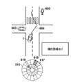
- control device 2 identifies pedestrian 600 as a risk factor because pedestrian 600 is walking toward the crosswalk. Pedestrian 600 is out of line-of-sight 601 of the driver. Therefore, the control device 2 displays the indicator 611 in the display area 310 with a high degree of emphasis (for example, dark red) as risk information. Indicator 611 indicates a distant position obliquely forward right of vehicle 1 where pedestrian 600 is located. Furthermore, the control device 2 displays the indicator 610 indicating the current traveling direction of the vehicle 1 with a low degree of emphasis (for example, light blue).
- a high degree of emphasis for example, dark red
- the control device 2 Since it is not necessary to draw the driver's attention to the current direction of travel of the vehicle 1, the control device 2 makes the indicator 610 less emphasized. Since indicator 610 does not need to show information about distance, indicator 610 uses two areas within the same sector of display area 310 .
- the control device 2 terminates the display of the indicator 611 and displays the indicator 612 in the display area 310 with a low degree of emphasis (for example, light red) as risk information. In other words, the control device 2 reduces the emphasis of risk information. Control device 2 continues to display indicator 610 .
- Control device 2 identifies vehicle 603 as a risk factor. Since the vehicle 603 is not in the line-of-sight direction 602 of the driver, the control device 2 displays the indicator 611 in the display area 310 with a high degree of emphasis (for example, dark red) as risk information. The indicator 613 indicates a position near the left oblique front of the vehicle 1 where the vehicle 603 is located. After that, as shown in FIG. 6C , when the vehicle 1 stops and the risk of the vehicle 1 contacting the pedestrian 600 and the vehicle 603 disappears, the control device 2 ends the display of the indicators 612 and 613 . Further, since the vehicle 1 is stopped, the control device 2 also ends the display of the indicator 610 indicating the traveling direction of the vehicle 1 .
- a high degree of emphasis for example, dark red
- the control device 2 turns the indicator 610 Instead, the indicator 614 is displayed in light blue. Indicator 614 indicates the direction of travel of vehicle 1 to avoid the risk factor (vehicle 603 in this example). Since the degree of urgency is not high and the steering operation is not performed using the steering operator, the control device 2 sets the indicator 614 to a low emphasis.
- the controller 2 directs the vehicle 1 to move along the path 604 (i.e., the steering wheel 31 A steering operation is performed by using the steering operation element so that the steering wheel is rotated to the right and then to the left.
- the control device 2 displays the indicator 617 in dark blue in the display area 310 as avoidance information.
- the indicator 617 indicates the direction in which the vehicle 1 should travel, that is, diagonally forward right. Indicator 617 does not need to show information about distance, so indicator 617 uses two areas within the same sector of display area 310 .
- the control device 2 terminates the display of the indicator 616, and instead displays the indicator 619 in the display area 310 with a low emphasis (for example, light red) as risk information.
- the indicator 619 indicates a near position diagonally left front of the vehicle 1 where the vehicle 603 is located.
- the control device 2 gives priority to the indicator 617, shifts the position of the indicator 615, and uses the indicator 618 to display the risk information of the pedestrian 600. indicates Indicator 618 is displayed with a low emphasis (eg, light red).
- control device 2 moves the position of the indicator 618 according to the change in the direction in which the vehicle 1 should travel as the vehicle 1 moves along the route 604 .
- control device 2 may display indicator 620 instead of indicator 618 .
- the direction of shifting the position of the indicator 615 is different from that in FIG. 7A.
- the control device 2 shifts the indicator 617 in a direction away from the route 604 of the vehicle 1 for avoiding the risk factor and displays it as an indicator 620 .
- Indicator 620 like indicator 618, is displayed with a low emphasis (eg, light red). This display makes it easier for the driver to steer to the left away from the direction indicated by indicator 620 after steering to the right according to indicator 617 . As a result, it becomes easier to guide the driver to drive along the route 604 .
- the above-described third embodiment will be described using another situation.
- the vehicle 1 is traveling on a road as shown in FIG. 8A.
- a vehicle 801 is stopped in front of the vehicle 1 .
- the control device 2 does not recognize the vehicle 801 at this point. Therefore, the control device 2 displays only the indicator 810 indicating the traveling direction of the vehicle 1 in the display area 310 with a low degree of emphasis (for example, light blue).
- the line-of-sight direction 802 of the driver faces forward.
- the control device 2 recognizes the vehicle 801 .
- the control device 2 identifies the vehicle 801 as a risk factor because the vehicle 801 runs off into the lane.
- the vehicle 801 is out of the driver's line of sight 802 . Therefore, the control device 2 displays the indicator 811 in the display area 310 with a high degree of emphasis (for example, dark red) as risk information.
- the indicator 811 indicates a distant position obliquely forward left of the vehicle 1 where the vehicle 801 is located. Control device 2 continues to display indicator 810 .
- the control device 2 terminates the display of the indicator 811 and displays the indicator 812 in the display area 310 with a low degree of emphasis (for example, light red) as risk information. In other words, the control device 2 reduces the emphasis of risk information. Control device 2 continues to display indicator 810 .
- the control device 2 uses the indicator 813 instead of the indicator 810. Display in light blue.
- the indicator 813 indicates the direction of travel of the vehicle 1 to avoid the risk factor (the vehicle 801 in this example). Since the degree of urgency is not high and the steering operation is not performed using the steering operator, the control device 2 sets the indicator 813 to a low emphasis.
- a steering guidance operation is performed using a steering operation member so as to rotate the wheel 31 in the right direction.
- the control device 2 displays the indicator 814 in dark blue in the display area 310 as avoidance information.
- the indicator 814 indicates the direction in which the vehicle 1 should travel, that is, diagonally forward right. Indicator 814 does not need to show information about distance, so indicator 814 uses two areas within the same sector of display area 310 . Control device 2 continues to display indicator 812 with a low emphasis.
- the control device 2 uses the steering control to direct the vehicle 1 to go straight (that is, to prevent the driver from turning the steering wheel 31), as shown in FIG. 9B. to perform the steering guidance operation.
- the control device 2 displays the indicator 815 in dark blue instead of the indicator 814 in the display area 310 as the avoidance information.
- vision can receive the most information among human senses. Therefore, it is effective to use a display device to inform the driver that there is a risk around the vehicle. However, if the driver does not see the information displayed on the display device, this information cannot inform the driver of the existence of the risk.
- the following embodiments make it possible to adequately inform the driver of the presence of risk.
- the risk identification unit 202 uses the environment around the vehicle 1 recognized by the environment recognition unit 201 and the current behavior of the vehicle 1 (for example, the speed, acceleration, direction of travel, etc. of the vehicle 1). Based on this, it is identified that there is a risk factor around the vehicle 1 .
- the risk identification unit 202 may further identify the direction of the risk factor with respect to the vehicle 1 and the distance from the vehicle 1 to the risk factor.
- a risk factor is a factor that poses a risk to the vehicle 1 with a probability equal to or greater than a threshold.
- the risks to which the vehicle 1 is subjected may include the vehicle 1 coming into contact with objects present in its surroundings.
- the risk identifying unit 202 may identify the object as a risk factor when the possibility of the vehicle 1 coming into contact with an object existing around the vehicle 1 is equal to or higher than a threshold value (for example, 30% or higher).
- Vehicle 1 contacting an object may include vehicle 1 colliding with an object.
- the risk that the vehicle 1 receives may be a risk other than contact, such as the vehicle 1 entering a travel-prohibited area or deviating from the track.
- the no-drive area is a risk factor.
- the notification determination unit 207 determines whether or not to notify the driver of information, and determines the content and manner of notification when the information is to be notified. For example, the notification determination unit 207 may determine to notify the driver of the existence of the risk factor when the risk factor exists around the vehicle 1 . The notification determination unit 207 may also determine to notify the driver of the direction of the risk factor to the vehicle 1, the distance from the vehicle 1 to the risk factor, or both. Details of the information notified to the driver will be described later.
- the output control unit 208 controls the operation of devices for notifying information to the driver, specifically the audio output device 91 and the display device 92 described above. For example, the output control unit 208 outputs information determined to be notified by the notification determination unit 207 to the driver through the audio output device 91 and/or the display device 92 . If the steering element of the vehicle 1, for example, the steering wheel 31 has a notification function, the output control unit 208 may control the operation of the steering wheel 31 so as to notify the driver of the information. For example, if the steering wheel 31 can vibrate, the output control unit 208 may notify the information by vibrating the steering wheel 31 .
- the display device 92 can display information indicating that a specific event has occurred. Moreover, the display device 92 may be capable of displaying information indicating the direction with respect to the vehicle 1 . In FIG. 3A, an indicator may be displayed in display area 300 to indicate that a particular event has occurred (eg, the presence of a risk factor around vehicle 1).
- a control method by the control device 2 related to the present disclosure will be described with reference to FIG.
- This operation may be started when the power of the vehicle 1 is turned on, or may be started in response to an instruction from the driver to start this operation.
- Each step of the method of FIG. 10 may be performed by the functional blocks of FIG. As such, each step of the method of FIG. 10 may be performed by a processor executing a program stored in memory. Alternatively or additionally, at least some steps of the method of FIG. 10 may be performed by dedicated circuitry.
- step S1001 the control device 2 (specifically, the environment recognition unit 201 and the line-of-sight detection unit 203) starts recognizing the surrounding environment of the vehicle 1 and detecting the line-of-sight direction of the driver. Recognition of the surrounding environment of the vehicle 1 and detection of the line-of-sight direction of the driver are continuously performed through the method of FIG.
- the environment recognition unit 201 may recognize the surrounding environment of the vehicle 1 at a predetermined cycle (for example, a cycle of 10 milliseconds to 100 milliseconds).
- the environment recognition unit 201 may store the recognition result in a storage device (eg, memory within the ECU) for a predetermined period (eg, 1 minute) for subsequent processing.
- the line-of-sight detection unit 203 may detect the line of sight of the driver at a predetermined cycle (for example, a cycle of 10 milliseconds).
- the line-of-sight detection unit 203 may store the detection result in a storage device (for example, memory in the ECU) for a predetermined period (for example, 1 minute) for subsequent processing.
- step S1002 the control device 2 (specifically, the risk identification unit 202) determines whether or not there is a risk around the vehicle 1. If it is determined that there is a risk ("YES” in step S1002), the control device 2 shifts the process to step S1003, otherwise ("NO” in step S1002), repeats step S1002.
- the control device 2 (specifically, the risk identification unit 202) identifies risk factors that cause the risk identified in step S1002.
- the control device 2 may or may not identify the direction of the risk factor with respect to the vehicle 1 and the distance from the vehicle 1 to the risk factor. Identification of the direction and distance of risk factors continues until it is determined that the risk has been eliminated.
- the risk identification unit 202 may identify the direction and distance of the risk factor at a predetermined cycle (for example, 10 millisecond cycle).
- step S1004 the control device 2 (specifically, the notification determination unit 207) determines whether the driver recognizes the risk factor identified in step S1003. When it is determined that the driver recognizes the risk factor ("YES" in step S1004), the control device 2 shifts the process to step S1010, otherwise ("NO" in step S1004). Then, the process transitions to step S1005.
- the notification determination unit 207 may determine whether the driver recognizes the risk factor based on the driver's line of sight. For example, the notification determining unit 207 determines whether the line of sight of the driver is directed toward the risk factor (for example, the risk factor is included within a predetermined range from the center of the line of sight), or the most recent (for example, within 1 minute) It may be determined that the driver recognizes the risk factor when the driver is facing the risk factor in the direction of the driver.
- the range of the driver's line of sight used to determine whether the driver is aware of the risk factor may be the range where the driver is considered to be gazing (hereinafter referred to as the gazing range). .
- the gaze range of the driver may be a predetermined range (for example, within 15 degrees from the center) from the center of the line of sight of the driver.
- the driver's gaze range may be a range narrower than the driver's field of view.
- the notification determining unit 207 may determine whether the driver recognizes the risk factor based on factors other than the driver's gaze direction. For example, the notification determining unit 207 may determine that the driver recognizes the risk factor when the driver steers the vehicle 1 away from the risk factor.
- step S1005 the control device 2 (specifically, the notification determination unit 207) determines whether the driver can visually recognize the display position of the risk information. If it is determined that the driver can visually recognize the display position of the risk information ("YES" in step S1005), the control device 2 shifts the process to step S1007; NO"), the process proceeds to step S1006.
- “Risk information” is information about the risk factors identified in step S1003.
- the risk information indicates that there are risk factors around the vehicle 1 .
- the risk information may also include the direction of the risk factor relative to the vehicle 1, the distance from the vehicle 1 to the risk factor, or both.
- the presence of risk factors in the surroundings of the vehicle 1 may be indicated, for example, by displaying the indicators of FIGS. 3A-3C.
- the direction of risk factors may be displayed using the indicators of FIGS. 3A-3C, for example.
- the distance to the risk factor may be displayed using the indicator of FIG. 3B, for example.
- the display of risk information continues until terminated in a step to be described later. By displaying the risk information, the driver's attention can be drawn in the direction of the risk, and the driver can easily recognize the risk.
- the display position of risk information is the position where the risk information is displayed on the display device 92.
- the display area 300 is the display position of the risk information.
- the display area 310 is the display position of the risk information.
- the LED row 320 is the display position of the risk information.
- the notification determination unit 207 may determine whether the driver can visually recognize the display position of the risk information based on the driver's line of sight. For example, the notification determination unit 207 estimates the visual field of the driver, and determines whether the driver can visually recognize the display position of the risk information based on whether the display position of the risk information is included in the estimated position of the driver. You can judge whether The driver's field of view may be estimated to be within a predetermined range from the center of the driver's line of sight (eg, within 80 degrees from the center).
- the notification determining unit 207 may determine whether the driver can visually recognize the display position of the risk information based on factors other than the driver's visual field. For example, the notification determination unit 207 may determine that the driver cannot visually recognize the display position of the risk information when the driver has his/her eyes closed.
- step S1006 the control device 2 (specifically, the output control unit 208) informs the driver that there is a risk factor around the vehicle 1 in a manner different from the display of the risk information at the display position of the risk information. to notify. Notification in a form different from the display of risk information at the display position of risk information is hereinafter referred to as auxiliary notification.
- Auxiliary notification may be made in a manner recognizable by senses other than sight.
- the auxiliary notification may be provided in an audibly perceptible manner.
- the output control unit 208 may output audible information indicating that a risk factor exists around the vehicle 1 .
- this audible information may be a warning sound of a predetermined pitch (e.g., a "beep, beep" sound) or a voice message conveying a message (e.g., "Be careful around your vehicle”). voice).
- supplementary notification with audible information may indicate the direction of risk factors.
- the output control unit 208 may indicate the direction of risk factors by adjusting the volume of audible information in each speaker. For example, when the vehicle 1 has speakers in the diagonally forward right and the diagonally forward left in the vehicle interior, the output control unit 208 outputs the audible information only from the diagonally forward right speaker so that the risk factor exists on the right side. By outputting audible information only from the front left speaker, it is indicated that the risk factor exists on the left side, and by outputting audible information only from the speakers on both sides, it is indicated that the risk factor exists in the direction of travel. may be indicated.
- the output control unit 208 may indicate the direction of risk factors by adjusting the sound quality of the audible information. For example, the output control unit 208 may indicate that there is a risk factor ahead of the vehicle 1 with high-pitched audible information, and indicate that there is a risk factor ahead of the vehicle 1 with low-pitched audible information. Alternatively or in addition to this, the output control unit 208 indicates the presence of the risk factor ahead of the vehicle 1 with audible information of the integer order harmonics, and non-indicates the presence of the risk factor ahead of the vehicle 1 . It may be indicated by audible information of integer order overtones.
- the output control unit 208 may indicate the direction of the risk factor by the content of the message (for example, "Beware of the diagonal left front of the vehicle").
- Auxiliary notification may be made in a tactile and recognizable manner.
- the output control unit 208 may indicate the presence of a risk factor in the surroundings by vibrating the steering controls (eg, the steering wheel 31) of the vehicle 1.
- FIG. This vibration may be intermittent or continuous.
- a vibrating auxiliary notification may indicate the direction of the risk factor.
- the output control unit 208 indicates that the risk factor exists on the right side by vibrating only the right side of the steering wheel, and indicates that the risk factor exists on the left side by vibrating only the left side of the steering wheel. and may indicate the presence of a risk factor in the direction of travel by vibrating both sides of the steering control.
- Auxiliary notification may be made using vision.
- the vehicle 1 may have an auxiliary display device such as an LED on the side of the passenger compartment, and the control device 2 may perform auxiliary notification by lighting or blinking the auxiliary display device. Even if the driver is looking at the side of the vehicle 1 and cannot see the display device in front of the passenger compartment, the display device on the side of the passenger compartment can be visually recognized in some cases.
- auxiliary notification By performing the auxiliary notification as described above, even if the driver cannot visually recognize the display position of the risk information, it is possible to inform the driver that there are risk factors around the vehicle 1. In addition, by not performing the auxiliary notification when the driver can visually recognize the display position of the risk information, it is possible to prevent excessive information from being notified to the driver.
- the various aspects of assisting operations described above may be performed in combination.
- step S1007 the control device 2 (specifically, the output control unit 208) does not make an auxiliary notification. If step S1006 has been executed by the operation so far and the auxiliary notification has been performed, the output control unit 208 ends the auxiliary notification. If the auxiliary notification has not been performed, the output control unit 208 does not perform processing in step S1007.
- step S1008 the control device 2 (specifically, the output control unit 208) displays the risk information on the display device 92.
- step S1009 the control device 2 (specifically, the risk identification unit 202) determines whether the risk identified in step S1002 has been eliminated. If the control device 2 determines that the risk has been eliminated ("YES" in step S1009), the process proceeds to step S1010; otherwise ("NO" in step S1009), the process proceeds to step S1004. Transition to The risk may be resolved by the behavior of the vehicle 1 (eg route change or speed change) or by the behavior of the risk factor (eg route change or speed change of other traffic participants).
- step S1010 the control device 2 (specifically, the output control unit 208) detects that the risk information is If it is displayed, the display is terminated, and if the auxiliary notification is being performed, the auxiliary notification is terminated.
- the control device 2 does not display risk information when the driver is aware of risk factors.
- the control device 2 may display risk information even when the driver is aware of risk factors.
- the control device 2 may display the risk information with a lower degree of emphasis than when the driver does not recognize the risk factor.
- the control device 2 displays the risk information on the display device 82 after making the auxiliary notification.
- This increases the possibility that the risk information will be displayed after the driver can visually recognize the display position of the risk information by the auxiliary notification. This makes it easier for the driver to recognize that risk information has been newly displayed.
- the control device 2 performs an auxiliary notification, and after it is determined that the driver can visually recognize the display position of the risk information, Risk information may be displayed on the display device 82 .
- the display of the risk information on the display device 82 and the supplementary notification may occur substantially simultaneously, or the display of the risk information on the display device 82 may occur faster than the supplementary notification. may be broken.
- FIGS. 11A to 12C Examples in which the control method of FIG. 10 is applied to various situations will be described with reference to FIGS. 11A to 12C.
- a case where the vehicle 1 travels in a country that has traffic regulations for driving on the left side will be described.
- the technology of the present disclosure may be applied when traveling in a country that has right-hand traffic regulations.
- FIG. 11A assume that vehicle 1 is running in front of a pedestrian crossing. Assume that a pedestrian 1101 is walking toward a crosswalk and a vehicle 1102 is traveling in the oncoming lane on the other side of the crosswalk. 11C shows the situation inside the vehicle 1.
- FIG. The display device 82 of the vehicle 1 is installed in the front center of the passenger compartment.
- a speaker 91L is installed diagonally forward left in the vehicle compartment, and a speaker 91R is installed diagonally forward right in the vehicle compartment.
- the control device 2 estimates a predetermined range centered on the direction of the vehicle 1102 as a gaze range 1103 of the driver, and determines a predetermined range centered on the direction of the vehicle 1102 to is estimated as the field of view 1104 of .
- Field of view 1104 is wider than gaze range 1103 .
- the control device 2 identifies the pedestrian 1101 as a risk factor because the pedestrian 1101 is walking toward the crosswalk. Since pedestrian 1101 is not included in driver's gaze range 1103 , controller 2 determines that pedestrian 1101 is not recognized by the driver. Therefore, the control device 2 displays an indicator 1105 in the display area 300 of the display device 82 as shown in FIG. 11B. Indicator 1105 indicates the presence of a risk factor (pedestrian 1101 in this example) and the direction of the risk factor with respect to vehicle 1 . Since the display position of the indicator 1105 is included in the field of view 1104 of the driver, the control device 2 does not make an auxiliary notification.
- FIG. 12A assumes vehicle 1 is about to turn right at a T-junction. Assume that a pedestrian 1201 is walking on a pedestrian crossing and a vehicle 1202 is traveling on the oncoming lane.
- FIG. 12C shows the situation inside the vehicle 1 .
- the display device 82 of the vehicle 1 is installed in the front center of the passenger compartment.
- a speaker 91L is installed diagonally forward left in the vehicle compartment, and a speaker 91R is installed diagonally forward right in the vehicle compartment.
- the control device 2 estimates a predetermined range centered on the direction of the pedestrian 1201 as a gaze range 1203 of the driver, and calculates a predetermined range centered on the direction of the pedestrian 1201. It is estimated as the driver's field of view 1204 . Field of view 1204 is wider than gaze range 1203 .
- control device 2 Since the vehicle 1202 is approaching the vehicle 1, the control device 2 identifies the vehicle 1202 as a risk factor. Since vehicle 1202 is not included in driver's gaze range 1203 , control device 2 determines that vehicle 1202 is not recognized by the driver. Therefore, the control device 2 displays an indicator 1205 in the display area 300 of the display device 82, as shown in FIG. 12B. Indicator 1205 indicates the presence of a risk factor (vehicle 1202 in this example) and indicates the direction of the risk factor to vehicle 1 .
- a risk factor vehicle 1202 in this example
- the control device 2 Since the display position of the indicator 1205 is not included in the field of view 1204 of the driver, the control device 2 makes an auxiliary notification. Specifically, the control device 2 outputs audible information (e.g., alarm sound) from the speaker 91L and outputs audible information (e.g., alarm sound) from the speaker 91R because the risk factor exists diagonally to the left of the vehicle 1. No output. Even if the driver cannot visually recognize the indicator 1205, the audible information allows the driver to know the existence of the risk factor around the vehicle 1 and the direction of the risk factor.
- audible information e.g., alarm sound
- the driver's attention can be drawn to the avoidance information, so that the driver can be steered to avoid the risk.
- Item 2 Item 1, wherein when the guidance control means performs the guidance action using the steering operation element, the display control means displays the risk information with a second emphasis level lower than the first emphasis level. controller. According to this item, the driver can easily recognize the direction in which the vehicle should be steered, and can also grasp the position of the risk factor.
- ⁇ Item 3> wherein, when the display position of the avoidance information overlaps with the display position of the risk information, the display control means shifts the display position of the risk information in a direction away from the route of the vehicle for avoiding the risk factor; 4.
- ⁇ Item 5> The control device according to item 1, wherein the display control means does not display the risk information when the guidance control means performs the guidance operation using the steering operator. This item makes it easier for the driver to recognize the direction in which the vehicle should be steered.
- line-of-sight detection means (203) for detecting the line-of-sight direction of the driver; further comprising recognition determination means (207) for determining whether the driver recognizes the risk factor based on the line-of-sight direction;
- the display control means when the risk factor exists and the guidance control means does not perform the guidance operation using the steering operator, displaying the risk information on the display device with the first emphasis when it is determined that the driver does not recognize the risk factor; Any one of items 1 to 5, wherein the risk information is displayed on the display device at a fourth emphasis level lower than the first emphasis level when it is determined that the driver recognizes the risk factor. 2.
- the control device according to item 1. According to this item, it becomes easier for the driver to grasp risks that the driver is not aware of.
- the risk identification means further identifies a distance to the risk factor, 7.
- a control device according to any one of items 1 to 6, wherein the risk information further indicates a distance to the risk factor. This item makes it easier for the driver to recognize the distance to the risk factor.
- the method according to any one of items 1 to 7, wherein the risk identifying means identifies the object existing around the vehicle as the risk factor when the possibility of the vehicle coming into contact with the object is equal to or greater than a threshold. Control device as described. According to this item, it becomes easier to suppress contact between the vehicle and the object.
- the display control means maintains the display of the risk information while the risk factor exists and the guidance control means does not perform the guidance operation using the steering operator. 2.
- the control device according to item 1. This item makes it easier for the driver to notice risk factors before the guidance action is performed.
- Control device according to any one of the preceding items, wherein said risk factors include traffic participants (501, 600, 603, 801) present in the surroundings of said vehicle. According to this item, the risk regarding traffic participants can be reduced.
- the induced action includes changing the torque for the driver to rotate the steering operation element, vibrating a specific portion of the steering operation element, and applying a rotational force to the steering operation element.
- a control device according to any one of items 1 to 10, comprising at least one of: According to this item, the driver can easily steer the vehicle in the desired direction.
- the control device according to any one of items 1 to 11, wherein the display control means displays the risk information and the avoidance information in different colors.
- This item makes it easier for the driver to distinguish between risk information and avoidance information.
- ⁇ Item 13> A vehicle (1) comprising a control device (2) according to any one of items 1 to 12. According to this item, the above effect can be obtained in the form of a vehicle.
- ⁇ Item 14> A program for causing a computer to function as each means of the control device according to any one of items 1 to 12. According to this item, the above effect can be obtained in the form of a program.
- a notification means (205) for performing an auxiliary notification to notify the driver in a manner different from the display of the risk information in the control device According to this item, the presence of the risk can be appropriately notified to the driver by performing the auxiliary notification when the driver cannot visually recognize the position of the risk information.
- the notification means sends the auxiliary notification when it is determined that the driver recognizes the risk factor, or when it is determined that the driver can visually recognize the display position of the risk information. 17.
- the controller of item 16 wherein no. According to this item, the driver's annoyance is reduced by not performing the auxiliary notification when unnecessary.
- the control device further comprises visual field estimation means (203) for estimating the visual field (1104, 1204) of the driver, The second determination means determines whether the driver can visually recognize the display position of the risk information based on whether the position where the risk information is displayed is included in the estimated visual field of the driver. 18.
- ⁇ Item 19> 19 19.
- the control device according to any one of items 16 to 18, wherein the auxiliary notification includes notifying the driver that the risk factor exists in a non-visually recognizable manner. According to this item, the presence of risk factors can be notified to the driver without depending on the driver's vision.
- a control device according to any one of items 16 to 19, wherein the auxiliary notification comprises outputting audible information indicating that the risk factor is present. According to this item, the presence of the risk factor can be notified to the driver regardless of the line-of-sight direction of the driver.
- ⁇ Item 22> 22. The control device according to any one of items 16 to 21, wherein the auxiliary notification includes vibrating an operating steering element of the vehicle.
- This item allows the driver to be notified of the presence of a risk factor regardless of the driver's line of sight or the presence of other audible information.
- the risk identifying means further identifies the direction of the risk factor for the vehicle; 23.
- Control device according to any one of items 16 to 22, wherein the risk information further indicates the direction of the risk factor. According to this item, the driver can be notified of the direction of the risk factor, and the driver can easily deal with the risk appropriately.
- the driver can be notified of the direction of the risk factor.
- the risk information 25 When it is determined that the driver does not recognize the risk factor and it is determined that the driver cannot visually recognize the display position of the risk information, after the auxiliary notification is made, the risk information 25.
- the control device according to any one of items 16 to 24, wherein is displayed. According to this item, it becomes easier for the driver to grasp that the risk information is newly displayed on the display device.
- a vehicle (1) comprising a control device (2) according to any one of items 16-25. According to this item, the above effect can be obtained in the form of a vehicle.
- ⁇ Item 27> A program for causing a computer to function as each means of the control device according to any one of items 16 to 25. According to this item, the above effect can be obtained in the form of a program.
- ⁇ Item 28> A control method for controlling a vehicle (1) having a display (82), comprising: a step of identifying the presence of risk factors (1101, 1202) around the vehicle (S1002); a step of displaying risk information (1105, 1205) indicating the presence of risk factors around the vehicle on the display device (S1008); determining whether the driver of the vehicle is aware of the risk factor (S1004); a step of determining whether the driver can visually recognize the display position of the risk information (S1005); When it is determined that the driver does not recognize the risk factor and it is determined that the driver is unable to visually recognize the display position of the risk information, the presence of the risk factor is determined by the display position.
- a step (S1006) of performing an auxiliary notification of notifying the driver in a manner different from the display of the risk information in the control method a step (S1006) of performing an auxiliary notification of notifying the driver in a manner different from the display of the risk information in the control method.
- the presence of the risk can be appropriately notified to the driver by performing the auxiliary notification when the driver cannot visually recognize the position of the risk information.
Landscapes
- Engineering & Computer Science (AREA)
- Transportation (AREA)
- Mechanical Engineering (AREA)
- Automation & Control Theory (AREA)
- Physics & Mathematics (AREA)
- Combustion & Propulsion (AREA)
- Chemical & Material Sciences (AREA)
- Human Computer Interaction (AREA)
- General Physics & Mathematics (AREA)
- Multimedia (AREA)
- Theoretical Computer Science (AREA)
- Mathematical Physics (AREA)
- Traffic Control Systems (AREA)
Abstract
This control device for controlling a vehicle that has a display device and a steering operation element comprises: a risk identification unit that identifies a risk factor which is present in the surroundings of the vehicle and the direction of the risk factor with respect to the vehicle; a display control unit that uses a first emphasis degree to display, on the display device, risk information indicative of the direction of the risk factor; and a guidance control unit that uses a steering operation element to carry out a guidance operation for guiding the driver of the vehicle to operate the steering operation element so as to avoid the risk factor. When the guidance control unit uses the steering operation element to carry out the guidance operation, the display control unit displays, on the display device, avoidance information indicative of the travelling direction of the vehicle for avoiding the risk factor and either displays the risk information with a second emphasis degree lower than the first emphasis degree or does not display the risk information.
Description
本発明は、車両並びにその制御装置及び制御方法に関する。
The present invention relates to a vehicle and its control device and control method.
車両の安全性を高めるための様々な技術が提案されている。特許文献1は、車両の運転者の視線方向を検出し、運転者が運転中に向けるべき方向を運転者が向いていない場合に、車両を安全な状態に制御することが記載されている。
Various technologies have been proposed to improve vehicle safety. Japanese Patent Laid-Open No. 2004-100001 describes detecting the line-of-sight direction of the driver of the vehicle and controlling the vehicle to a safe state when the driver is not facing the direction that the driver should be facing during driving.
車両に発生するリスクを回避するために、運転者に車両が進むべき方向を示すことが考えられる。しかし、この情報の提示の仕方によっては、運転者がどの方向に車両を進めればいいかを直感的に判断できない場合がある。本発明の一部の側面は、リスクを回避するように運転者による操舵を誘導することを目的とする。
In order to avoid the risks that occur in the vehicle, it is conceivable to indicate the direction in which the vehicle should go to the driver. However, depending on how this information is presented, the driver may not be able to intuitively determine in which direction the vehicle should proceed. Some aspects of the present invention aim to guide steering by the driver to avoid risks.
上記課題に鑑みて、表示装置及び操舵操作子を有する車両を制御するための制御装置であって、前記車両の周囲に存在するリスク要因と、前記車両に対する前記リスク要因の方向とを特定するリスク特定手段と、前記リスク要因の方向を示すリスク情報を前記表示装置に第1強調度で表示する表示制御手段と、前記リスク要因を回避するように前記車両の運転者が前記操舵操作子を操作することを誘導する誘導動作を、前記操舵操作子を用いて行う誘導制御手段と、を備え、前記誘導制御手段が前記操舵操作子を用いて前記誘導動作を行う場合に、前記表示制御手段は、前記リスク要因を回避するための前記車両の進行方向を示す回避情報を前記表示装置に表示することと、前記リスク情報を前記第1強調度よりも低い第2強調度で表示するか、又は前記リスク情報を表示しないことと、を行う、制御装置が提供される。
In view of the above problems, there is provided a control device for controlling a vehicle having a display device and a steering operator, the risk factor identifying a risk factor existing around the vehicle and a direction of the risk factor with respect to the vehicle. identification means; display control means for displaying risk information indicating the direction of the risk factor on the display device with a first emphasis; and a driver of the vehicle operating the steering operator so as to avoid the risk factor. Guidance control means for performing a guidance operation using the steering operation element to guide the display control means to displaying, on the display device, avoidance information indicating the traveling direction of the vehicle for avoiding the risk factor; and displaying the risk information with a second emphasis lower than the first emphasis, or and not displaying the risk information.
上記手段により、リスクを回避するように運転者による操舵を誘導できる。
The above means can guide the driver to steer to avoid risks.
本発明のその他の特徴及び利点は、添付図面を参照とした以下の説明により明らかになるであろう。なお、添付図面においては、同じ若しくは同様の構成には、同じ参照番号を付す。
Other features and advantages of the present invention will become apparent from the following description with reference to the accompanying drawings. In the accompanying drawings, the same or similar configurations are given the same reference numerals.
添付図面は明細書に含まれ、その一部を構成し、本発明の実施の形態を示し、その記述と共に本発明の原理を説明するために用いられる。
実施形態に係る車両のハードウェア構成例を説明するブロック図。
実施形態に係る制御装置の機能構成例を説明するブロック図。
実施形態に係る表示装置の表示例を説明する模式図。
実施形態に係る表示装置の表示例を説明する模式図。
実施形態に係る表示装置の表示例を説明する模式図。
実施形態に係る制御方法を説明するフローチャート。
実施形態に係る制御方法を説明するフローチャート。
実施形態に係る制御方法の様々な実施例を説明する模式図。
実施形態に係る制御方法の様々な実施例を説明する模式図。
実施形態に係る制御方法の様々な実施例を説明する模式図。
実施形態に係る制御方法の様々な実施例を説明する模式図。
実施形態に係る制御方法の様々な実施例を説明する模式図。
実施形態に係る制御方法の様々な実施例を説明する模式図。
実施形態に係る制御方法の様々な実施例を説明する模式図。
実施形態に係る制御方法の様々な実施例を説明する模式図。
実施形態に係る制御方法の様々な実施例を説明する模式図。
実施形態に係る制御方法の様々な実施例を説明する模式図。
実施形態に係る制御方法の様々な実施例を説明する模式図。
実施形態に係る制御方法の様々な実施例を説明する模式図。
実施形態に係る制御方法の様々な実施例を説明する模式図。
実施形態に係る制御方法の様々な実施例を説明する模式図。
実施形態に係る制御方法の様々な実施例を説明する模式図。
実施形態に係る制御方法の様々な実施例を説明する模式図。
実施形態に係る制御方法を説明するフローチャート。
実施形態に係る制御方法の様々な実施例を説明する模式図。
実施形態に係る制御方法の様々な実施例を説明する模式図。
実施形態に係る制御方法の様々な実施例を説明する模式図。
実施形態に係る制御方法の様々な実施例を説明する模式図。
実施形態に係る制御方法の様々な実施例を説明する模式図。
実施形態に係る制御方法の様々な実施例を説明する模式図。
The accompanying drawings, which are incorporated in and constitute a part of the specification, illustrate embodiments of the invention and, together with the description, serve to explain the principles of the invention.
FIG. 2 is a block diagram for explaining a hardware configuration example of the vehicle according to the embodiment; FIG. FIG. 2 is a block diagram for explaining a functional configuration example of a control device according to the embodiment; 4A and 4B are schematic diagrams for explaining display examples of the display device according to the embodiment; 4A and 4B are schematic diagrams for explaining display examples of the display device according to the embodiment; 4A and 4B are schematic diagrams for explaining display examples of the display device according to the embodiment; 4 is a flowchart for explaining a control method according to the embodiment; 4 is a flowchart for explaining a control method according to the embodiment; Schematic diagrams for explaining various examples of a control method according to an embodiment. Schematic diagrams for explaining various examples of a control method according to an embodiment. Schematic diagrams for explaining various examples of a control method according to an embodiment. Schematic diagrams for explaining various examples of a control method according to an embodiment. Schematic diagrams for explaining various examples of a control method according to an embodiment. Schematic diagrams for explaining various examples of a control method according to an embodiment. Schematic diagrams for explaining various examples of a control method according to an embodiment. Schematic diagrams for explaining various examples of a control method according to an embodiment. Schematic diagrams for explaining various examples of a control method according to an embodiment. Schematic diagrams for explaining various examples of a control method according to an embodiment. Schematic diagrams for explaining various examples of a control method according to an embodiment. Schematic diagrams for explaining various examples of a control method according to an embodiment. Schematic diagrams for explaining various examples of a control method according to an embodiment. Schematic diagrams for explaining various examples of a control method according to an embodiment. Schematic diagrams for explaining various examples of a control method according to an embodiment. Schematic diagrams for explaining various examples of a control method according to an embodiment. 4 is a flowchart for explaining a control method according to the embodiment; Schematic diagrams for explaining various examples of a control method according to an embodiment. Schematic diagrams for explaining various examples of a control method according to an embodiment. Schematic diagrams for explaining various examples of a control method according to an embodiment. Schematic diagrams for explaining various examples of a control method according to an embodiment. Schematic diagrams for explaining various examples of a control method according to an embodiment. Schematic diagrams for explaining various examples of a control method according to an embodiment.
以下、添付図面を参照して実施形態を詳しく説明する。なお、以下の実施形態は特許請求の範囲に係る発明を限定するものではなく、また実施形態で説明されている特徴の組み合わせの全てが発明に必須のものとは限らない。実施形態で説明されている複数の特徴のうち二つ以上の特徴は任意に組み合わされてもよい。また、同一若しくは同様の構成には同一の参照番号を付し、重複した説明は省略する。
Hereinafter, embodiments will be described in detail with reference to the accompanying drawings. It should be noted that the following embodiments do not limit the invention according to the claims, and not all combinations of features described in the embodiments are essential to the invention. Two or more of the features described in the embodiments may be combined arbitrarily. Also, the same or similar configurations are denoted by the same reference numerals, and redundant explanations are omitted.
図1は、本発明の一実施形態に係る車両1のブロック図である。図1において、車両1はその概略が平面図と側面図とで示されている。車両1は一例としてセダンタイプの四輪の乗用車である。車両1はこのような四輪車両であってもよいし、二輪車両や他のタイプの車両であってもよい。
FIG. 1 is a block diagram of a vehicle 1 according to one embodiment of the invention. In FIG. 1, a vehicle 1 is shown schematically in a plan view and a side view. The vehicle 1 is, for example, a sedan-type four-wheel passenger car. The vehicle 1 may be such a four-wheeled vehicle, a two-wheeled vehicle, or any other type of vehicle.
車両1は、車両1を制御する車両用制御装置2(以下、単に制御装置2と呼ぶ)を含む。制御装置2は車内ネットワークにより通信可能に接続された複数のECU20~29を含む。各ECUは、CPUに代表されるプロセッサ、半導体メモリ等のメモリ、外部デバイスとのインタフェース等を含む。メモリにはプロセッサが実行するプログラムやプロセッサが処理に使用するデータ等が格納される。各ECUはプロセッサ、メモリおよびインタフェース等を複数備えていてもよい。例えば、ECU20は、プロセッサ20aとメモリ20bとを備える。メモリ20bに格納されたプログラムが含む命令をプロセッサ20aが実行することによって、ECU20による処理が実行される。これに代えて、ECU20は、ECU20による処理を実行するためのASIC等の専用の集積回路を備えてもよい。他のECUについても同様である。
The vehicle 1 includes a vehicle control device 2 (hereinafter simply referred to as the control device 2) that controls the vehicle 1. The control device 2 includes a plurality of ECUs 20 to 29 communicatively connected by an in-vehicle network. Each ECU includes a processor represented by a CPU, a memory such as a semiconductor memory, an interface with an external device, and the like. The memory stores programs executed by the processor, data used for processing by the processor, and the like. Each ECU may include a plurality of processors, memories, interfaces, and the like. For example, the ECU 20 includes a processor 20a and a memory 20b. Processing by the ECU 20 is executed by the processor 20a executing instructions included in the program stored in the memory 20b. Alternatively, the ECU 20 may include a dedicated integrated circuit such as an ASIC for executing processing by the ECU 20 . The same applies to other ECUs.
以下、各ECU20~29が担当する機能等について説明する。なお、ECUの数や、担当する機能については適宜設計可能であり、本実施形態よりも細分化したり、統合したりすることが可能である。
The functions that each ECU 20 to 29 takes charge of will be described below. Note that the number of ECUs and the functions they are in charge of can be designed as appropriate, and it is possible to subdivide or integrate them more than in the present embodiment.
ECU20は、車両1の自動走行に関わる制御を実行する。自動運転においては、車両1の操舵と、加減速の少なくともいずれか一方を自動制御する。ECU20による自動走行は、車両1の運転者(以下、単に運転者とも表す))による走行操作を必要としない自動走行(自動運転とも呼ばれうる)と、運転者による走行操作を支援するための自動走行(運転支援とも呼ばれうる)とを含んでもよい。
The ECU 20 executes control related to automatic driving of the vehicle 1 . In automatic driving, at least one of steering and acceleration/deceleration of the vehicle 1 is automatically controlled. Automatic driving by the ECU 20 includes automatic driving (also referred to as automatic driving) that does not require a driving operation by the driver of the vehicle 1 (hereinafter simply referred to as a driver), and automatic driving for assisting the driving operation by the driver. Automatic driving (which can also be called driving assistance) may be included.
ECU21は、電動パワーステアリング装置3を制御する。電動パワーステアリング装置3は、ステアリングホイール31に対する運転者の運転操作(操舵操作)に応じて前輪を操舵する機構を含む。ステアリングホイール31は、操舵操作子の一例である。また、電動パワーステアリング装置3は操舵操作をアシストしたり、前輪を自動操舵したりするための駆動力を発揮するモータや、操舵角を検知するセンサ等を含む。車両1の運転状態が自動運転の場合、ECU21は、ECU20からの指示に対応して電動パワーステアリング装置3を自動制御し、車両1の進行方向を制御する。
The ECU 21 controls the electric power steering device 3. The electric power steering device 3 includes a mechanism that steers the front wheels according to the driver's driving operation (steering operation) on the steering wheel 31 . The steering wheel 31 is an example of a steering operator. Further, the electric power steering device 3 includes a motor that exerts a driving force for assisting the steering operation and automatically steering the front wheels, a sensor that detects the steering angle, and the like. When the driving state of the vehicle 1 is automatic driving, the ECU 21 automatically controls the electric power steering device 3 in response to instructions from the ECU 20 to control the traveling direction of the vehicle 1 .
ECU22および23は、車両の周囲状況を検知する検知ユニット41~43の制御および検知結果の情報処理を行う。検知ユニット41は、車両1の前方を撮影するカメラであり(以下、カメラ41と表記する場合がある。)、本実施形態の場合、車両1のルーフ前部でフロントウィンドウの車室内側に取り付けられる。カメラ41が撮影した画像の解析により、物標の輪郭抽出や、道路上の車線の区画線(白線等)を抽出可能である。
The ECUs 22 and 23 control the detection units 41 to 43 that detect the vehicle's surroundings and process information on the detection results. The detection unit 41 is a camera for photographing the front of the vehicle 1 (hereinafter sometimes referred to as the camera 41), and in the case of this embodiment, is attached to the interior side of the front window in the front part of the roof of the vehicle 1. be done. By analyzing the image captured by the camera 41, it is possible to extract the outline of the target and the lane markings (white lines, etc.) on the road.
検知ユニット42は、ライダ(Light Detection and Ranging)であり(以下、ライダ42と表記する場合がある)、車両1の周囲の物標を検知したり、物標との距離を測距したりする。本実施形態の場合、ライダ42は5つ設けられており、車両1の前部の各隅部に1つずつ、後部中央に1つ、後部各側方に1つずつ設けられている。検知ユニット43は、ミリ波レーダであり(以下、レーダ43と表記する場合がある)、車両1の周囲の物標を検知したり、物標との距離を測距したりする。本実施形態の場合、レーダ43は5つ設けられており、車両1の前部中央に1つ、前部各隅部に1つずつ、後部各隅部に一つずつ設けられている。
The detection unit 42 is a lidar (Light Detection and Ranging) (hereinafter sometimes referred to as the lidar 42), and detects targets around the vehicle 1 and measures the distance to the target. . In this embodiment, five riders 42 are provided, one at each corner of the front of the vehicle 1, one at the center of the rear, and one at each side of the rear. The detection unit 43 is a millimeter wave radar (hereinafter sometimes referred to as the radar 43), detects targets around the vehicle 1, and measures the distance to the targets. In this embodiment, five radars 43 are provided, one in the center of the front portion of the vehicle 1, one in each corner of the front portion, and one in each corner of the rear portion.
ECU22は、一方のカメラ41と、各ライダ42の制御および検知結果の情報処理を行う。ECU23は、他方のカメラ41と、各レーダ43の制御および検知結果の情報処理を行う。車両の周囲状況を検知する装置を二組備えたことで、検知結果の信頼性を向上でき、また、カメラ、ライダ、レーダといった種類の異なる検知ユニットを備えたことで、車両の周辺環境の解析を多面的に行うことができる。
The ECU 22 controls the one camera 41 and each rider 42 and processes the detection results. The ECU 23 performs control of the other camera 41 and each radar 43 and information processing of detection results. Equipped with two sets of devices to detect the vehicle's surroundings, the reliability of detection results can be improved. can be performed in a multifaceted manner.
ECU24は、ジャイロセンサ5、GPSセンサ24b、通信装置24cの制御および検知結果あるいは通信結果の情報処理を行う。ジャイロセンサ5は車両1の回転運動を検知する。ジャイロセンサ5の検知結果や、車輪速等により車両1の進路を判定することができる。GPSセンサ24bは、車両1の現在位置を検知する。通信装置24cは、地図情報や交通情報を提供するサーバと無線通信を行い、これらの情報を取得する。ECU24は、メモリに構築された地図情報のデータベース24aにアクセス可能であり、ECU24は現在地から目的地へのルート探索等を行う。ECU24、地図データベース24a、GPSセンサ24bは、いわゆるナビゲーション装置を構成している。
The ECU 24 controls the gyro sensor 5, the GPS sensor 24b, and the communication device 24c, and performs information processing of detection results or communication results. A gyro sensor 5 detects rotational motion of the vehicle 1 . The course of the vehicle 1 can be determined based on the detection result of the gyro sensor 5, the wheel speed, and the like. GPS sensor 24 b detects the current position of vehicle 1 . The communication device 24c performs wireless communication with a server that provides map information and traffic information, and acquires these information. The ECU 24 can access a database 24a of map information constructed in memory, and performs route search from the current location to the destination. The ECU 24, map database 24a, and GPS sensor 24b constitute a so-called navigation device.
ECU25は、車車間通信用の通信装置25aを備える。通信装置25aは、周辺の他車両と無線通信を行い、車両間での情報交換を行う。
The ECU 25 includes a communication device 25a for inter-vehicle communication. The communication device 25a performs wireless communication with other vehicles in the vicinity to exchange information between the vehicles.
ECU26は、パワープラント6を制御する。パワープラント6は車両1の駆動輪を回転させる駆動力を出力する機構であり、例えば、エンジンと変速機とを含む。ECU26は、例えば、アクセルペダル7Aに設けた操作検知センサ7aにより検知した運転者の運転操作(アクセル操作あるいは加速操作)に対応してエンジンの出力を制御したり、車速センサ7cが検知した車速等の情報に基づいて変速機の変速段を切り替えたりする。車両1の運転状態が自動運転の場合、ECU26は、ECU20からの指示に対応してパワープラント6を自動制御し、車両1の加減速を制御する。
The ECU 26 controls the power plant 6. The power plant 6 is a mechanism that outputs driving force for rotating the drive wheels of the vehicle 1, and includes, for example, an engine and a transmission. For example, the ECU 26 controls the output of the engine in response to the driver's driving operation (accelerator operation or acceleration operation) detected by the operation detection sensor 7a provided on the accelerator pedal 7A, or detects the vehicle speed detected by the vehicle speed sensor 7c. The gear stage of the transmission is switched based on the information. When the driving state of the vehicle 1 is automatic driving, the ECU 26 automatically controls the power plant 6 in response to instructions from the ECU 20 to control the acceleration and deceleration of the vehicle 1 .
ECU27は、方向指示器8(ウィンカ)を含む灯火器(ヘッドライト、テールライト等)を制御する。図1の例の場合、方向指示器8は車両1の前部、ドアミラーおよび後部に設けられている。
The ECU 27 controls lights (headlights, taillights, etc.) including the direction indicators 8 (winkers). In the example of FIG. 1, the direction indicators 8 are provided at the front, door mirrors and rear of the vehicle 1 .
ECU28は、入出力装置9の制御を行う。入出力装置9は運転者に対する情報の出力と、運転者からの情報の入力の受け付けを行う。音声出力装置91は運転者に対して音声により情報を通知する。表示装置92は運転者に対して画像の表示により情報を通知する。表示装置92は例えば運転席表面に配置され、インストルメントパネル等を構成する。なお、ここでは、音声と表示を例示したが振動や光により情報を通知してもよい。また、音声、表示、振動または光のうちの複数を組み合わせて情報を通知してもよい。さらに、通知すべき情報のレベル(例えば緊急度)に応じて、組み合わせを異ならせたり、通知態様を異ならせたりしてもよい。入力装置93は運転者が操作可能な位置に配置され、車両1に対する指示を行うスイッチ群であるが、音声入力装置も含まれてもよい。
The ECU 28 controls the input/output device 9. The input/output device 9 outputs information to the driver and receives information input from the driver. The voice output device 91 notifies the driver of information by voice. The display device 92 notifies the driver of information by displaying an image. The display device 92 is arranged, for example, on the surface of the driver's seat and constitutes an instrument panel or the like. Note that although audio and display are exemplified here, information may be notified by vibration or light. Information may also be notified by combining a plurality of sounds, displays, vibrations, and lights. Furthermore, depending on the level of information to be notified (for example, the degree of urgency), different combinations may be used, and different notification modes may be used. The input device 93 is a group of switches arranged at a position operable by the driver to give instructions to the vehicle 1, but may also include a voice input device.
ECU29は、ブレーキ装置10やパーキングブレーキ(不図示)を制御する。ブレーキ装置10は例えばディスクブレーキ装置であり、車両1の各車輪に設けられ、車輪の回転に抵抗を加えることで車両1を減速あるいは停止させる。ECU29は、例えば、ブレーキペダル7Bに設けた操作検知センサ7bにより検知した運転者の運転操作(ブレーキ操作)に対応してブレーキ装置10の作動を制御する。車両1の運転状態が自動運転の場合、ECU29は、ECU20からの指示に対応してブレーキ装置10を自動制御し、車両1の減速および停止を制御する。ブレーキ装置10やパーキングブレーキは車両1の停止状態を維持するために作動することもできる。また、パワープラント6の変速機がパーキングロック機構を備える場合、これを車両1の停止状態を維持するために作動することもできる。
The ECU 29 controls the braking device 10 and a parking brake (not shown). The brake device 10 is, for example, a disc brake device, is provided on each wheel of the vehicle 1, and decelerates or stops the vehicle 1 by applying resistance to the rotation of the wheels. The ECU 29 controls the operation of the brake device 10 in response to the driver's driving operation (brake operation) detected by the operation detection sensor 7b provided on the brake pedal 7B, for example. When the driving state of the vehicle 1 is automatic driving, the ECU 29 automatically controls the braking device 10 in response to instructions from the ECU 20 to control deceleration and stopping of the vehicle 1 . The brake device 10 and the parking brake can also be operated to keep the vehicle 1 stopped. Moreover, if the transmission of the power plant 6 is equipped with a parking lock mechanism, it can also be operated to keep the vehicle 1 in a stopped state.
ECU30は、運転者カメラ44を制御する。運転者カメラ44は、運転者(とりわけ、その顔)を撮影する位置に取り付けられている。ECU30は、運転者カメラ44によって撮影された運転者の画像を解析することによって、運転者の状態を特定する。例えば、ECU30は、運転者の顔の向き及び瞳の位置に基づいて、運転者の視線方向を特定してもよい。また、ECU30は、運転者の目が開いているかどうかや、頭部の動きなどに基づいて、運転者が居眠りしていることを特定してもよい。
The ECU 30 controls the driver's camera 44. A driver camera 44 is attached at a position for photographing the driver (particularly, his face). The ECU 30 identifies the state of the driver by analyzing the image of the driver captured by the driver camera 44 . For example, the ECU 30 may identify the line-of-sight direction of the driver based on the orientation of the driver's face and the positions of the pupils. Further, the ECU 30 may identify whether the driver is dozing off based on whether the driver's eyes are open or the movement of the head.
図2を参照して、車両1の制御装置2の機能ブロックについて説明する。制御装置2は、図2に示される複数の機能ブロックを有してもよい。制御装置2の各機能ブロックは、図1で説明した制御装置2のECU20~30のうちの1つ以上によって実現されてもよい。具体的に、各機能ブロックによる動作は、ECU20~30のうちの1つ以上のもののCPU(例えば、CPU20a)が、対応するメモリ(例えば、メモリ20b)に記憶されたプログラムの命令を実行することによって実現されてもよい。これに加えて又はこれに代えて、各機能ブロックによる動作は、ASIC(特定用途向け集積回路)やFPGA(フィールドプログラマブルゲートアレイ)のような専用回路によって実現されてもよい。
The functional blocks of the control device 2 of the vehicle 1 will be described with reference to FIG. The control device 2 may have multiple functional blocks shown in FIG. Each functional block of the control device 2 may be implemented by one or more of the ECUs 20 to 30 of the control device 2 described with reference to FIG. Specifically, the operation of each functional block is that the CPU (for example, CPU 20a) of one or more of the ECUs 20 to 30 executes the instructions of the program stored in the corresponding memory (for example, memory 20b). may be realized by Additionally or alternatively, the operation of each functional block may be implemented by dedicated circuitry such as an ASIC (Application Specific Integrated Circuit) or FPGA (Field Programmable Gate Array).
環境認識部201は、検知ユニット41~43による検知結果に基づいて、車両1の周囲の環境を認識する。車両1の周囲とは、検知ユニット41~43による検知範囲のことであってもよい。車両1の周囲の環境は、例えば、静的構造と、交通参加者とを含む。静的構造は、道路(区画線、横断歩道、道路の形状などを含む)と、道路に対して永続的又は半永続的に設置された物体、例えば信号機、標識などとを含む。交通参加者は、車両1以外の車両(四輪車及び二輪車を含む)、自転車、歩行者などを含む。交通参加者は、移動中の交通参加者(例えば、走行中の車両や歩行中の歩行者)と、静止している交通参加者(例えば、一時停止中の車両、停車中の車両、立ち止まっている歩行者)との両方を含んでもよい。車両1の周辺環境を認識することは、上述した物体の位置、大きさ、移動方向、移動速度などを認識することを含んでもよい。環境認識部201による周辺環境の認識は、例えば既存の技術を用いて実行されてもよいため、詳細な説明を省略する。
The environment recognition unit 201 recognizes the environment around the vehicle 1 based on the detection results of the detection units 41-43. The surroundings of the vehicle 1 may be the detection range of the detection units 41-43. The environment around the vehicle 1 includes, for example, static structures and traffic participants. Static structures include roads (including lane markings, pedestrian crossings, road geometry, etc.) and objects permanently or semi-permanently installed on roads, such as traffic lights, signs, and the like. Traffic participants include vehicles other than the vehicle 1 (including four-wheeled vehicles and two-wheeled vehicles), bicycles, pedestrians, and the like. Traffic participants can be divided into moving traffic participants (e.g. moving vehicles and walking pedestrians) and stationary traffic participants (e.g. stopped vehicles, stopped vehicles, standing still). and pedestrians). Recognizing the surrounding environment of the vehicle 1 may include recognizing the position, size, movement direction, movement speed, and the like of the objects described above. Recognition of the surrounding environment by the environment recognition unit 201 may be performed using, for example, an existing technology, so detailed description thereof will be omitted.
リスク特定部202は、環境認識部201によって認識された車両1の周囲の環境と、車両1の現在の挙動(例えば、車両1の速度、加速度、進行方向など)とに基づいて、車両1の周囲に存在するリスク要因と、車両1に対するリスク要因の方向とを特定する。リスク特定部202は、車両1からリスク要因までの距離をさらに特定してもよい。リスク要因とは、閾値以上の可能性で車両1にリスクを与える要因のことである。車両1が受けるリスクは、車両1の周囲に存在する物体に車両1が接触することを含んでもよい。リスク特定部202は、車両1の周囲に存在する物体に車両1が接触する可能性が閾値以上(例えば、30%以上)である場合に、当該物体をリスク要因として特定してもよい。車両1が物体と接触することは、車両1が物体と衝突することを含んでもよい。さらに、車両1が受けるリスクは、接触以外のリスク、例えば、車両1が走行禁止エリアに進入することや、車両1が崖から落ちることであってもよい。この例の場合に、走行禁止エリアや崖がリスク要因となる。
The risk identification unit 202 identifies the vehicle 1 based on the environment around the vehicle 1 recognized by the environment recognition unit 201 and the current behavior of the vehicle 1 (for example, the speed, acceleration, traveling direction, etc. of the vehicle 1). A risk factor present in the surroundings and a direction of the risk factor to the vehicle 1 are identified. The risk identification unit 202 may further identify the distance from the vehicle 1 to the risk factor. A risk factor is a factor that poses a risk to the vehicle 1 with a probability equal to or greater than a threshold. The risks to which the vehicle 1 is subjected may include the vehicle 1 coming into contact with objects present in its surroundings. The risk identifying unit 202 may identify the object as a risk factor when the possibility of the vehicle 1 coming into contact with an object existing around the vehicle 1 is equal to or higher than a threshold value (for example, 30% or higher). Vehicle 1 contacting an object may include vehicle 1 colliding with an object. Furthermore, the risk that the vehicle 1 receives may be a risk other than contact, such as the vehicle 1 entering a travel-prohibited area or falling off a cliff. In this example, no-driving areas and cliffs are risk factors.
リスク要因は、車両1の周囲に存在する交通参加者であってもよい。例えば、リスク特定部202は、車両1の進路上に歩行者が飛び出す可能性があると判定した場合に、この歩行者をリスク要因として特定してもよい。リスク要因は、道路に設置された物体であってもよい。例えば、リスク特定部202は、車両1が走行中の車線の前方で道路工事が行われている場合に、道路工事に使用される器具(例えば、立ち入り禁止の標識など)をリスク要因として特定してもよい。リスク特定部202は、車両1に不利益を与える可能性を、車両1の周囲に存在する物体の将来の(例えば、現時点(算出時点)から30秒後までの)予測位置と、車両1の将来の予測位置とに基づいて算出してもよい。
The risk factors may be traffic participants present around the vehicle 1. For example, when the risk identification unit 202 determines that there is a possibility that a pedestrian may run out onto the course of the vehicle 1, the risk identification unit 202 may identify this pedestrian as a risk factor. A risk factor may be an object placed on the road. For example, when road construction is being performed in front of the lane in which the vehicle 1 is traveling, the risk identification unit 202 identifies tools used in the road construction (for example, no entry signs, etc.) as risk factors. may The risk identification unit 202 determines the possibility of giving a disadvantage to the vehicle 1 by using the future predicted position of an object existing around the vehicle 1 (for example, from the current time (calculated time) to 30 seconds later) and the position of the vehicle 1 It may be calculated based on future predicted positions.
リスク特定部202は、リスクの緊急度を決定してもよい。リスクの緊急度とは、車両1がリスクを回避するためにどれくらいの時間的な余裕があるかを表す指標のことである。例えば、車両1と接触する可能性がある物体がリスク要因として特定された場合に、リスクの緊急度は、車両1が当該物体と接触するまでの予測時間に基づいて決定されてもよい。リスク特定部202によるリスク要因、その方向及び距離、並びにリスクの緊急度の特定は、例えば既存の技術を用いて実行されてもよいため、詳細な説明を省略する。
The risk identification unit 202 may determine the urgency of the risk. The degree of urgency of risk is an index representing how much time the vehicle 1 has to avoid the risk. For example, when an object that may come into contact with the vehicle 1 is identified as a risk factor, the urgency of the risk may be determined based on the estimated time until the vehicle 1 comes into contact with the object. The identification of the risk factor, its direction and distance, and the degree of urgency of the risk by the risk identification unit 202 may be performed using, for example, existing technology, so detailed description thereof will be omitted.
視線検出部203は、運転者カメラ44によって得られた画像を解析することによって、運転者の視線方向を検出する。視線検出部203による視線の検出は、例えば既存の技術を用いて実行されてもよいため、詳細な説明を省略する。
The line-of-sight detection unit 203 detects the line-of-sight direction of the driver by analyzing the image obtained by the driver's camera 44 . Since detection of the line of sight by the line of sight detection unit 203 may be performed using, for example, an existing technique, detailed description thereof will be omitted.
回避行動計画部204は、環境認識部201によって認識された車両1の周囲の環境と、車両1の現在の挙動(例えば、車両1の速度、加速度、進行方向など)と、リスク特定部202によって特定されたリスク要因並びにその方向及び緊急度とに基づいて、リスク要因を回避するために車両1が取るべき挙動を決定する。車両1が取るべき挙動は、車両1を加速、減速又は速度維持することと、車両1を特定の操舵状態にすることとを含んでもよい。
The avoidance action planning unit 204 uses the environment around the vehicle 1 recognized by the environment recognition unit 201, the current behavior of the vehicle 1 (for example, the speed, acceleration, traveling direction, etc. of the vehicle 1), and the risk identification unit 202 to Based on the identified risk factor and its direction and urgency, it determines the behavior that the vehicle 1 should take to avoid the risk factor. Behaviors to be taken by the vehicle 1 may include accelerating, decelerating or maintaining the speed of the vehicle 1 and placing the vehicle 1 into a particular steering state.
例えば、回避行動計画部204は、車両1の前方にリスク要因があり、車両1がリスク要因と接触するまでに予測時間が長い(例えば、10秒以上)場合に、車両1が減速すべきであることを決定してもよい。回避行動計画部204は、車両1の左斜め前方にリスク要因があり、車両1がリスク要因と接触するまでに予測時間が短い(例えば、5秒以下)場合に、車両1が減速しつつ、右方向に旋回すべきであることを決定してもよい。回避行動計画部204は、車両1の両側にリスク要因がある(例えば、壁と崖に挟まれている)場合に、車両1が直進を維持すべきであることを決定してもよい。回避行動計画部204による挙動の決定は、例えば既存の技術を用いて実行されてもよいため、詳細な説明を省略する。
For example, the avoidance action planning unit 204 determines that the vehicle 1 should decelerate when there is a risk factor ahead of the vehicle 1 and the estimated time until the vehicle 1 comes into contact with the risk factor is long (for example, 10 seconds or more). You may decide to be The avoidance action planning unit 204 decelerates the vehicle 1 when there is a risk factor diagonally left ahead of the vehicle 1 and the predicted time until the vehicle 1 comes into contact with the risk factor is short (for example, 5 seconds or less). It may decide that it should turn right. The avoidance action planner 204 may determine that the vehicle 1 should remain straight when there are risk factors on both sides of the vehicle 1 (eg, between walls and cliffs). Determination of the behavior by the avoidance action planning unit 204 may be performed using, for example, existing technology, so detailed description thereof will be omitted.
制動制御部205は、車両1の制動を制御する。例えば、制動制御部205は、回避行動計画部204によって車両1を減速すべきであると決定された場合に、自動的に(すなわち、ブレーキペダル7Bが操作されていない場合であっても)車両1を制動することによって、車両1を減速、さらには停止してもよい。
The braking control unit 205 controls braking of the vehicle 1. For example, when the avoidance action planning unit 204 determines that the vehicle 1 should be decelerated, the braking control unit 205 automatically (that is, even if the brake pedal 7B is not operated) brakes the vehicle. By braking 1 the vehicle 1 may be slowed down or even stopped.
操舵誘導部206は、車両1の操舵操作子を用いて操舵誘導動作を行う。操舵誘導動作とは、リスク要因を回避するように運転者が操舵操作子を操作することを誘導するための動作のことである。以下、車両1の操舵操作子として、図1のステアリングホイール31を例として説明する。例えば、回避行動計画部204によって、車両1が右方向に旋回すべきであることが決定されたとする。この場合に、運転者が右方向へステアリングホイール31を回転することを誘導するために、操舵誘導部206は、以下の動作を行ってもよい。
The steering guidance unit 206 performs a steering guidance operation using the steering operator of the vehicle 1 . The steering guidance operation is an operation for guiding the driver to operate the steering operation element so as to avoid risk factors. The steering wheel 31 in FIG. 1 will be described below as an example of the steering operator of the vehicle 1 . For example, assume that the avoidance action planning unit 204 determines that the vehicle 1 should turn right. In this case, in order to guide the driver to turn the steering wheel 31 to the right, the steering guidance section 206 may perform the following operations.
例えば、操舵誘導部206は、ステアリングホイール31の右側の特定の部分を所定の時間(例えば、1秒間や3秒間)振動することによって、運転者にステアリングホイール31を右方向に回転することを促してもよい。操舵誘導部206は、この振動を1回だけ行ってもよいし、所定の間隔(例えば、5秒間)で複数回(例えば、3回)行ってもよいし、リスク要因が解消されるまで繰り返してもよい。操舵誘導部206は、ステアリングホイール31に回転方向(この例では、右回転方向)の力を与えることによって、運転者にステアリングホイール31を右方向に回転することを促してもよい。回転方向の力は、運転者がステアリングホイール31を把持していない場合に所定量(例えば、1度、5度又は10度など)だけステアリングホイール31が回転する力であってもよい。運転者がステアリングホイール31を把持している場合に、ステアリングホイール31が実際に回転してもよいし回転しなくてもよい。このような力をステアリングホイール31に与えることによって、運転者は、特定の回転方向への打感をステアリングホイール31から受ける。操舵誘導部206は、ステアリングホイール31に回転方向の力を与えることによってステアリングホイール31が実際に回転した場合に、この回転を戻すようにステアリングホイール31に逆回転方向の力を与えてもよいし、このような逆回転方向の力を与えなくてもよい。操舵誘導部206は、ステアリングホイール31への回転方向の力の付与を1回だけ行ってもよいし、所定の間隔(例えば、5秒間)で複数回(例えば、3回)行ってもよいし、リスク要因が解消されるまで繰り返してもよい。操舵誘導部206は、ステアリングホイール31を右方向に回転するためのトルクを低減することによって、運転者が右方向にステアリングホイール31を回転しやすくしてもよい。操舵誘導部206は、これらの動作のうちの一部又は全部を組み合わせたものを操舵誘導動作としてもよい。回避行動計画部204によって、車両1が左方向に旋回すべきであることが決定された場合に、操舵誘導部206は、上記の動作と逆方向の動作を行えばよい。
For example, the steering guidance unit 206 prompts the driver to turn the steering wheel 31 to the right by vibrating a specific portion on the right side of the steering wheel 31 for a predetermined time (for example, 1 second or 3 seconds). may The steering guidance unit 206 may perform this vibration only once, may perform this vibration a plurality of times (for example, three times) at predetermined intervals (for example, 5 seconds), or repeat until the risk factor is eliminated. may The steering guidance unit 206 may prompt the driver to rotate the steering wheel 31 to the right by applying force to the steering wheel 31 in the direction of rotation (right rotation in this example). The rotational force may be a force that rotates the steering wheel 31 by a predetermined amount (eg, 1 degree, 5 degrees, 10 degrees, etc.) when the steering wheel 31 is not held by the driver. When the driver holds the steering wheel 31, the steering wheel 31 may or may not actually rotate. By applying such a force to the steering wheel 31, the driver receives a hitting feeling from the steering wheel 31 in a specific rotational direction. When the steering wheel 31 actually rotates by applying a rotational force to the steering wheel 31, the steering guide unit 206 may apply a force in the reverse rotational direction to the steering wheel 31 so as to reverse the rotation. , it is not necessary to apply such force in the reverse rotation direction. The steering guidance unit 206 may apply the force in the rotational direction to the steering wheel 31 only once, or may apply the force a plurality of times (eg, three times) at predetermined intervals (eg, 5 seconds). may be repeated until the risk factor is eliminated. The steering guidance unit 206 may reduce the torque for rotating the steering wheel 31 in the right direction, thereby making it easier for the driver to rotate the steering wheel 31 in the right direction. The steering guidance unit 206 may use a combination of some or all of these operations as the steering guidance operation. When the avoidance action planning section 204 determines that the vehicle 1 should turn to the left, the steering guidance section 206 may perform the above operation in the opposite direction.
回避行動計画部204によって、車両1が直進すべきである(すなわち、何れの方向にも旋回すべきでない)ことが決定されたとする。この場合に、操舵誘導部206は、ステアリングホイール31を回転するためのトルクを増大してもよい。車両1の操舵状態が、直進及び右旋回のみを許容し、左旋回を許容しない状態となるように運転者を誘導するために、操舵誘導部206は、ステアリングホイール31を左方向に回転するためのトルクのみを増大してもよい。
Assume that the avoidance action planning unit 204 has determined that the vehicle 1 should go straight (that is, should not turn in any direction). In this case, the steering guidance section 206 may increase the torque for rotating the steering wheel 31 . The steering guidance unit 206 rotates the steering wheel 31 to the left in order to guide the driver so that the steering state of the vehicle 1 permits only straight traveling and turning to the right, but does not permit turning to the left. You may increase only the torque for.
通知決定部207は、運転者に対して情報を通知するかどうかを決定し、情報を通知する場合にその内容及び通知方法を決定する。例えば、通知決定部207は、車両1の周囲にリスク要因が存在する場合に、運転者に対してリスク要因の方向を通知することを決定してもよい。また、通知決定部207は、運転者に対して車両1からリスク要因までの距離を通知することを決定してもよい。さらに、通知決定部207は、リスク要因を回避するための車両1の進行方向を通知することを決定してもよい。運転者に対して通知される情報の詳細については後述する。
The notification determination unit 207 determines whether or not to notify the driver of the information, and determines the content and method of notification when the information is to be notified. For example, the notification determination unit 207 may determine to notify the driver of the direction of the risk factor when the risk factor exists around the vehicle 1 . The notification determination unit 207 may also determine to notify the driver of the distance from the vehicle 1 to the risk factor. Furthermore, the notification determination unit 207 may determine to notify the traveling direction of the vehicle 1 for avoiding risk factors. Details of the information notified to the driver will be described later.
出力制御部208は、運転者に対して情報を通知するための装置、具体的に上述の音声出力装置91及び表示装置92の動作を制御する。例えば、出力制御部208は、通知決定部207によって通知することが決定された情報を、音声出力装置91及び/又は表示装置92を通じて運転者に向けて出力する。
The output control unit 208 controls the operation of devices for notifying information to the driver, specifically the audio output device 91 and the display device 92 described above. For example, the output control unit 208 outputs information determined to be notified by the notification determination unit 207 to the driver through the audio output device 91 and/or the display device 92 .
図3A~図3Cを参照して、運転者に向けて情報を表示するための表示装置92について説明する。表示装置92は、車両1に対する方向を示す情報を表示可能である。さらに、表示装置92は、車両1からの距離を示す情報を表示可能であってもよい。表示装置92は、これらの情報を表示可能な任意の表示装置であってもよい。例えば、表示装置92は、車両1のインストルメントパネルに取り付けられたドットマトリックス方式のディスプレイであってもよい。また、表示装置92は、特定の形状で発光可能な複数の発光部の集合であってもよい。さらに、表示装置92は、ヘッドアップディスプレイであってもよい。
A display device 92 for displaying information to the driver will be described with reference to FIGS. 3A to 3C. The display device 92 can display information indicating the direction with respect to the vehicle 1 . Furthermore, the display device 92 may be able to display information indicating the distance from the vehicle 1 . Display device 92 may be any display device capable of displaying such information. For example, the display device 92 may be a dot-matrix display attached to the instrument panel of the vehicle 1 . Moreover, the display device 92 may be a set of a plurality of light-emitting portions capable of emitting light in a specific shape. Furthermore, the display device 92 may be a head-up display.
表示装置92は、車両1に対する方向を示すために、図3Aに示すような円形の表示領域300を有してもよい。表示領域300は、表示装置92の一部分を占める。表示装置92は、表示領域300内の任意の位置に扇形のインジケータを表示可能である。表示領域300は、インジケータを表示していない場合に、ベース色(例えば、白色や黒色)で表示される。インジケータは、表示領域300のうちインジケータ以外の部分と区別可能に表示される。例えば、インジケータはベース色とは異なる色(例えば、赤色や青色)で表示され、インジケータ以外の部分はベース色で表示される。これに代えて又はこれに加えて、インジケータは、特定の部分を点滅することによって表示されてもよい。
The display device 92 may have a circular display area 300 as shown in FIG. 3A to indicate the direction with respect to the vehicle 1 . Display area 300 occupies a portion of display device 92 . The display device 92 can display a fan-shaped indicator at any position within the display area 300 . The display area 300 is displayed in a base color (for example, white or black) when no indicator is displayed. The indicator is displayed so as to be distinguishable from the portion of the display area 300 other than the indicator. For example, the indicator is displayed in a color (eg, red or blue) different from the base color, and the portion other than the indicator is displayed in the base color. Alternatively or additionally, the indicators may be displayed by flashing certain portions.
表示領域300のインジケータは、車両1に対する方向を示す。例えば、表示領域300の中心に対するインジケータの位置と、車両1に対する方向とが対応付けられてもよい。図3Aの例では、図面上向きが車両1の前方に対応し、図面下向きが車両1の後方に対応し、図面右向きが車両1の右側方に対応し、図面左向きが車両1の左側方に対応する。図3Aに、インジケータの一例として、インジケータ301を示す。インジケータ301は、例えば赤色で表示されてもよい。インジケータ301は、車両1の左斜め前方を示す。
The indicator in the display area 300 indicates the direction with respect to the vehicle 1. For example, the position of the indicator with respect to the center of the display area 300 and the direction with respect to the vehicle 1 may be associated. In the example of FIG. 3A, the upward direction in the drawing corresponds to the front of the vehicle 1, the downward direction in the drawing corresponds to the rear of the vehicle 1, the rightward direction in the drawing corresponds to the right side of the vehicle 1, and the leftward direction in the drawing corresponds to the left side of the vehicle 1. do. FIG. 3A shows an indicator 301 as an example of an indicator. Indicator 301 may be displayed in red, for example. The indicator 301 indicates the oblique left front of the vehicle 1 .
表示装置92は、同じ色ですべてのインジケータを表示してもよいし、複数の色から選択された色で各インジケータを表示してもよい。また、表示装置92は、同じ強調度ですべてのインジケータを表示してもよいし、複数の強調度から選択された強調度で各インジケータを表示してもよい。強調度とは、運転者の注意のひきつけやすさを表す指標のことである。強調度が高いほど、運転者の注意をひきつけやすい。例えば、表示装置92は、インジケータを異なる濃度又は輝度で表示してもよい。濃度又は輝度が高いほど強調度が高くなる。例えば、濃い赤色の方が薄い赤色よりも運転者の注意をひきつけやすい。これに代えて又はこれに加えて、表示装置92は、インジケータを異なる態様で表示してもよい。例えば、表示装置92は、インジケータの強調度を高めるために、インジケータを点滅させてもよい。
The display device 92 may display all indicators in the same color, or may display each indicator in a color selected from a plurality of colors. Further, the display device 92 may display all indicators with the same degree of emphasis, or may display each indicator with a degree of emphasis selected from a plurality of degrees of emphasis. The degree of emphasis is an index representing the ease of attracting the driver's attention. The higher the degree of emphasis, the easier it is to attract the driver's attention. For example, the display device 92 may display the indicators with different densities or brightness. The higher the density or brightness, the higher the enhancement. For example, a dark red color is more likely to attract the driver's attention than a light red color. Alternatively or additionally, the display device 92 may display the indicators differently. For example, the display device 92 may flash the indicator to increase the emphasis of the indicator.
表示装置92は、車両1に対する方向と車両1からの距離とを示すために、図3Bに示すような円形の表示領域310を有してもよい。以下、表示領域300と表示領域310との相違点について主に説明する。表示領域310は、全周(すなわち、360度)が16個の扇形に分割されており、各扇形が中心から近い方と遠い方との2つに分割されている。したがって、表示領域310は、中心からの方向及び距離が互いに異なる32個の領域を有する。表示装置92は、表示領域310の32個の領域のうちの1つ以上を使用してインジケータを表示する。
The display device 92 may have a circular display area 310 as shown in FIG. 3B to indicate the direction to and distance from the vehicle 1 . Differences between the display area 300 and the display area 310 will be mainly described below. The display area 310 is divided into 16 sectors along the entire circumference (that is, 360 degrees), and each sector is divided into two, one closer to the center and one farther from the center. Therefore, the display area 310 has 32 areas with different directions and distances from the center. Display device 92 displays indicators using one or more of the 32 areas of display area 310 .
表示領域300と同様に、表示領域310のインジケータは、車両1に対する方向を示す。例えば、表示領域310の中心に対するインジケータの位置と、車両1に対する方向とが対応付けられてもよい。さらに、表示領域310のインジケータは、車両1からの距離を示す。例えば、表示領域310の中心からのインジケータの距離(近いか遠いか)と、車両1からの距離とが対応付けられてもよい。表示領域310の例では、車両1からの距離が2段階で示されるが、3段階以上で示されてもよい。
As with the display area 300 , the indicators in the display area 310 indicate the direction with respect to the vehicle 1 . For example, the position of the indicator with respect to the center of the display area 310 and the direction with respect to the vehicle 1 may be associated. Furthermore, indicators in the display area 310 show the distance from the vehicle 1 . For example, the distance (close or far) of the indicator from the center of the display area 310 may be associated with the distance from the vehicle 1 . In the example of the display area 310, the distance from the vehicle 1 is shown in two steps, but it may be shown in three steps or more.
図3Bに、インジケータの一例として、インジケータ311及び312を示す。インジケータ311は、車両1の右斜め前方の遠い位置を示す。インジケータ311は、例えば濃い赤色で表示されてもよい。インジケータ312は、車両1の左側方前側の近い位置を示す。インジケータ312は、例えば薄い赤色で表示されてもよい。この例では、インジケータ311の強調度の方がインジケータ312の強調度よりも高い。
FIG. 3B shows indicators 311 and 312 as examples of indicators. The indicator 311 indicates a distant position obliquely forward right of the vehicle 1 . Indicator 311 may be displayed in dark red, for example. The indicator 312 indicates a near position on the front left side of the vehicle 1 . Indicator 312 may be displayed in light red, for example. In this example, the emphasis of indicator 311 is higher than the emphasis of indicator 312 .
表示装置92は、車両1に対する方向を示すために、図3Cに示すようなLED(発光ダイオード)列320を含んでもよい。LED列320は、一列に並んだ複数のLEDで構成されてもよい。表示装置92は、LED列320のうちの選択した部分を点灯可能であり、点灯した部分がインジケータとなる。LED列320は、車両1のフロントガラスの下部に設置されている。LED列320のインジケータと、車両1に対する方向とは互いに対応してもよい。例えば、運転者の頭部を始点とし、インジケータを通る線分が車両1に対する方向を示してもよい。図3Cに、インジケータの一例として、インジケータ321を示す。インジケータ321は、車両1の左斜め前方を示す。
The display device 92 may include an LED (light emitting diode) string 320 as shown in FIG. 3C to indicate the direction relative to the vehicle 1 . The LED string 320 may consist of a plurality of LEDs arranged in a line. The display device 92 can light a selected portion of the LED row 320, and the lighted portion serves as an indicator. The LED row 320 is installed below the windshield of the vehicle 1 . The indicator of the LED string 320 and the direction with respect to the vehicle 1 may correspond to each other. For example, a line segment starting from the driver's head and passing through the indicator may indicate the direction with respect to the vehicle 1 . FIG. 3C shows an indicator 321 as an example of an indicator. The indicator 321 indicates the oblique left front of the vehicle 1 .
上述の例では、インジケータの位置によって車両1に対する方向が示される。これに代えて、車両1に対する方向は他の方法によって示されてもよい。例えば、車両1に対する方法は、「前方」、「右斜め前方」のような言葉で示されてもよいし、矢印などの記号で示されてもよい。
In the above example, the direction relative to the vehicle 1 is indicated by the position of the indicator. Alternatively, the direction relative to vehicle 1 may be indicated by other methods. For example, the directions for the vehicle 1 may be indicated by words such as "forward" and "diagonally forward to the right", or may be indicated by symbols such as arrows.
上述の例では、インジケータの位置によって車両1からの距離が示される。これに代えて、車両1からの距離は他の方法によって示されてもよい。例えば、車両1からの距離は、算用数字で表示されてもよいし、2点間の距離(例えば、矢印の先端と後端との間の距離)によって示されてもよい。
In the above example, the distance from the vehicle 1 is indicated by the position of the indicator. Alternatively, the distance from vehicle 1 may be indicated by other methods. For example, the distance from the vehicle 1 may be indicated by Arabic numerals or indicated by the distance between two points (for example, the distance between the tip and the rear end of an arrow).
図4A及び図4Bを参照して、本開示に関連する制御装置2による制御方法について説明する。この動作は、車両1の電源がオンになった時点で開始されてもよいし、運転者が本動作の開始を指示したことに応じて開始されてもよい。図4A及び図4Bの方法の各工程は、図2の機能ブロックによって実行されてもよい。そのため、図4A及び図4Bの方法の各工程は、メモリに記憶されたプログラムをプロセッサが実行することによって実行されてもよい。これに代えて又はこれに加えて、図4A及び図4Bの方法の少なくとも一部の工程は、専用回路によって実行されてもよい。
A control method by the control device 2 related to the present disclosure will be described with reference to FIGS. 4A and 4B. This operation may be started when the power of the vehicle 1 is turned on, or may be started in response to an instruction from the driver to start this operation. Each step of the method of FIGS. 4A and 4B may be performed by the functional blocks of FIG. As such, the steps of the methods of FIGS. 4A and 4B may be performed by a processor executing a program stored in memory. Alternatively or additionally, at least some steps of the methods of FIGS. 4A and 4B may be performed by dedicated circuitry.
ステップS401で、制御装置2(具体的に、環境認識部201及び視線検出部203)は、車両1の周辺環境の認識と、運転者の視線方向の検出とを開始する。車両1の周辺環境の認識と、運転者の視線方向の検出とは、図4A及び図4Bの方法を通じて継続的に行われる。例えば、環境認識部201は、車両1の周辺環境の認識を所定の周期(例えば10ミリ秒~100ミリ秒周期)で行ってもよい。環境認識部201は、認識結果を後続の処理のための所定期間(例えば、1分間)、記憶装置(例えば、ECU内のメモリ)に記憶しておいてもよい。視線検出部203は、運転者の視線の検出を所定の周期(例えば10ミリ秒周期)で行ってもよい。視線検出部203は、検出結果を後続の処理のための所定期間(例えば、1分間)、記憶装置(例えば、ECU内のメモリ)に記憶しておいてもよい。
In step S401, the control device 2 (specifically, the environment recognition unit 201 and the line-of-sight detection unit 203) starts recognizing the surrounding environment of the vehicle 1 and detecting the line-of-sight direction of the driver. Recognition of the surrounding environment of the vehicle 1 and detection of the driver's gaze direction are continuously performed through the methods of FIGS. 4A and 4B. For example, the environment recognition unit 201 may recognize the surrounding environment of the vehicle 1 at a predetermined cycle (for example, a cycle of 10 milliseconds to 100 milliseconds). The environment recognition unit 201 may store the recognition result in a storage device (eg, memory within the ECU) for a predetermined period (eg, 1 minute) for subsequent processing. The line-of-sight detection unit 203 may detect the line of sight of the driver at a predetermined cycle (for example, a cycle of 10 milliseconds). The line-of-sight detection unit 203 may store the detection result in a storage device (for example, memory in the ECU) for a predetermined period (for example, 1 minute) for subsequent processing.
ステップS402で、制御装置2(具体的に、リスク特定部202)は、車両1の周囲にリスクが存在するかどうかを判定する。制御装置2は、リスクが存在すると判定された場合(ステップS402で「YES」)に、処理をステップS403に遷移し、それ以外の場合(ステップS402で「NO」)に、ステップS402を繰り返す。
At step S402, the control device 2 (specifically, the risk identification unit 202) determines whether or not there is a risk around the vehicle 1. If it is determined that there is a risk ("YES" in step S402), the control device 2 shifts the process to step S403, otherwise ("NO" in step S402), repeats step S402.
ステップS403で、制御装置2(具体的に、リスク特定部202)は、ステップS402で特定されたリスクを引き起こすリスク要因と、車両1に対するリスク要因の方向と、当該リスクの緊急度とを特定する。制御装置2(具体的に、リスク特定部202)は、車両1からリスク要因までの距離を特定してもよいし、特定しなくてもよい。リスク要因の方向(及び場合によっては距離)の特定と、リスクの緊急度の特定とは、リスクが解消したと判定されるまで、継続的に行われる。例えば、リスク特定部202は、リスク要因の方向(及び場合によっては距離)の特定と、リスクの緊急度の特定とを所定の周期(例えば10ミリ秒周期)で行ってもよい。
In step S403, the control device 2 (specifically, the risk identification unit 202) identifies the risk factor that causes the risk identified in step S402, the direction of the risk factor to the vehicle 1, and the degree of urgency of the risk. . The control device 2 (specifically, the risk identification unit 202) may or may not identify the distance from the vehicle 1 to the risk factor. Determining the direction (and possibly distance) of the risk factor and determining the urgency of the risk continues until it is determined that the risk has been eliminated. For example, the risk identification unit 202 may identify the direction (and possibly the distance) of the risk factor and the degree of urgency of the risk at predetermined intervals (for example, 10 millisecond intervals).
ステップS404で、制御装置2(具体的に、通知決定部207)は、ステップS403で特定されたリスク要因を運転者が認識しているかどうかを判定する。制御装置2は、運転者がリスク要因を認識していると判定された場合(ステップS404で「YES」)に、処理をステップS405に遷移し、それ以外の場合(ステップS404で「NO」)に、処理をステップS406に遷移する。
In step S404, the control device 2 (specifically, the notification determination unit 207) determines whether the driver recognizes the risk factor identified in step S403. When it is determined that the driver recognizes the risk factor ("YES" in step S404), the control device 2 shifts the process to step S405, otherwise ("NO" in step S404). Then, the process transitions to step S406.
通知決定部207は、運転者の視線方向に基づいて、運転者がリスク要因を認識しているかどうかを判定してもよい。例えば、通知決定部207は、例えば、運転者の視線方向がリスク要因の方を向いている(例えば、視線の中心から所定の範囲内にリスク要因が含まれる)、又は直近(例えば、1分以内)にリスク要因の方向を向いていた場合に、運転者がリスク要因を認識していると判定してもよい。通知決定部207は、運転者の視線方向以外に基づいて、運転者がリスク要因を認識しているかどうかを判定してもよい。例えば、通知決定部207は、運転者がリスク要因から遠ざかるように車両1を操舵したことに応じて、運転者がリスク要因を認識していると判定してもよい。
The notification determination unit 207 may determine whether the driver recognizes the risk factor based on the driver's line of sight. For example, the notification determining unit 207 determines whether the line of sight of the driver is directed toward the risk factor (for example, the risk factor is included within a predetermined range from the center of the line of sight), or the most recent (for example, one minute It may be determined that the driver is aware of the risk factor when the driver faces the risk factor within ). The notification determining unit 207 may determine whether the driver recognizes the risk factor based on factors other than the driver's line of sight. For example, the notification determining unit 207 may determine that the driver recognizes the risk factor when the driver steers the vehicle 1 away from the risk factor.
ステップS405で、制御装置2(具体的に、出力制御部208)は、リスク情報を表示装置92に低い強調度で表示し、ステップS406で、制御装置2(具体的に、出力制御部208)は、リスク情報を表示装置92に高い強調度で表示する。このように、出力制御部208は、運転者がリスク要因を認識していないと判定された場合に、リスク情報を表示装置92に高い強調度で表示し、運転者がリスク要因を認識していると判定された場合に、リスク情報を表示装置92に低い強調度で表示する。ステップS405において強調度が低いとは、ステップS406における強調度と比較して低いことを意味する。
In step S405, the control device 2 (specifically, the output control unit 208) displays the risk information on the display device 92 with a low degree of emphasis, and in step S406, the control device 2 (specifically, the output control unit 208) displays the risk information on the display device 92 with a high degree of emphasis. In this way, when it is determined that the driver does not recognize the risk factor, the output control unit 208 displays the risk information on the display device 92 with a high degree of emphasis so that the driver does not recognize the risk factor. risk information is displayed on the display device 92 with a low degree of emphasis. A low degree of emphasis in step S405 means that the degree of emphasis in step S406 is lower than that in step S406.
リスク情報とは、ステップS403で特定されたリスク要因に関する情報のことである。例えば、リスク情報は、車両1に対するリスク要因の方向を含む。リスク情報はさらに、車両1からリスク要因までの距離を含んでもよい。リスク要因の方向を含むリスク情報は、例えば図3A~図3Cのインジケータを用いて表示されてもよい。リスク要因の方向とリスク要因までの距離とを含むリスク情報は、例えば図3Bのインジケータを用いて表示されてもよい。リスク情報の表示は、後述するステップにおいて終了されるまで継続される。リスク情報を表示することによって、運転者の注意をリスク方向に引き付けることができ、運転者がリスクを認識しやすくなる。
"Risk information" is information about the risk factors identified in step S403. For example, risk information includes the direction of risk factors for vehicle 1 . Risk information may further include the distance from the vehicle 1 to the risk factor. Risk information, including direction of risk factors, may be displayed using the indicators of FIGS. 3A-3C, for example. Risk information, including the direction of the risk factor and the distance to the risk factor, may be displayed using the indicator of FIG. 3B, for example. The display of risk information continues until terminated in a step to be described later. By displaying the risk information, the driver's attention can be drawn in the direction of the risk, and the driver can easily recognize the risk.
上述のステップS404~S406の動作は、リスク要因が存在し、かつ操舵誘導動作が行われない間、繰り返される。そのため、リスク要因が存在し、かつ操舵誘導動作が行われない間、出力制御部208は、リスク情報の表示を維持する。運転者が最初にリスク要因を認識せず、リスク情報が高い強調度で表示された後に、運転者がリスク要因に気付いた(認識した)場合に、出力制御部208は、ステップS405を実行し、リスク情報を低い強調度で表示する、すわなち、リスク情報の強調度を下げることになる。
The operations of steps S404 to S406 described above are repeated while there is a risk factor and no steering guidance operation is performed. Therefore, the output control unit 208 maintains the display of the risk information while the risk factor exists and the steering guidance operation is not performed. When the driver does not recognize the risk factor at first and the driver notices (recognizes) the risk factor after the risk information is displayed with a high degree of emphasis, the output control unit 208 executes step S405. , to display the risk information with a lower emphasis, ie to reduce the emphasis of the risk information.
ステップS407で、制御装置2(具体的に、リスク特定部202)は、ステップS402で特定されたリスクが解消したかどうかを判定する。制御装置2は、リスクが解消したと判定された場合(ステップS407で「YES」)に、処理をステップS414に遷移し、それ以外の場合(ステップS407で「NO」)に、処理をステップS408に遷移する。リスクは、車両1の挙動(例えば、経路変更や速度変更)によって解消することもあるし、リスク要因の挙動(例えば、他の交通参加者の経路変更や速度変更)によって解消することもある。車両1の挙動は、運転者の操作によるものであってもよいし、制動制御部205の動作によるものであってもよい。
At step S407, the control device 2 (specifically, the risk identification unit 202) determines whether the risk identified at step S402 has been eliminated. If the control device 2 determines that the risk has been eliminated ("YES" in step S407), the process proceeds to step S414. Otherwise ("NO" in step S407), the process proceeds to step S408. transition to The risk may be resolved by the behavior of the vehicle 1 (eg route change or speed change) or by the behavior of the risk factor (eg route change or speed change of other traffic participants). The behavior of the vehicle 1 may be based on the driver's operation or may be based on the operation of the braking control unit 205 .
リスクが解消したと判定された場合に、ステップS414で、制御装置2(具体的に、出力制御部208)は、表示装置92におけるリスク情報の表示を終了する。
When it is determined that the risk has been eliminated, the control device 2 (specifically, the output control unit 208) terminates the display of risk information on the display device 92 in step S414.
ステップS408で、制御装置2(具体的に、通知決定部207)は、リスクの緊急度に基づいて、操舵操作子を用いて操舵誘導動作を行うかどうかを判定する。制御装置2は、操舵誘導動作を行うと判定された場合(ステップS408で「YES」)に、処理をステップS409に遷移し、それ以外の場合(ステップS408で「NO」)に、処理をステップS404に遷移する。上述したように、通知決定部207は、リスクの緊急度が高く、リスク要因を回避するために車両1の操舵が必要である場合に、操舵操作子を用いて操舵誘導動作を行うと判定してもよい。
In step S408, the control device 2 (specifically, the notification determination unit 207) determines whether or not to perform a steering guidance operation using the steering operator based on the urgency of the risk. When it is determined that the steering guidance operation is to be performed ("YES" in step S408), the control device 2 shifts the process to step S409; Transition to S404. As described above, the notification determination unit 207 determines that the steering operation is to be performed using the steering operator when the risk is highly urgent and the vehicle 1 needs to be steered to avoid the risk factor. may
ステップS409で、制御装置2(具体的に、出力制御部208)は、回避情報を表示装置92に表示する。回避情報とは、リスク要因を回避するための車両1の進行方向を示す情報のことである。例えば、リスク要因が車両1の左側に存在する場合に、回避情報は、車両1の右斜め前方を示してもよい。車両1の進行方向を含む回避情報は、例えば図3A~図3Cのインジケータを用いて表示されてもよい。出力制御部208は、回避情報を、リスク情報を表示するために使用した色とは異なる色で表示してもよいし、回避情報とリスク情報とを同じ色で表示してもよい。例えば、出力制御部208は、リスク情報を赤色で表示し、回避情報を青色で表示してもよい。回避情報を表示することによって、運転者がどの方向に車両1を操舵すればよいかを認識しやすくなり、車両1の安全性が向上する。
In step S409, the control device 2 (specifically, the output control unit 208) displays the avoidance information on the display device 92. The avoidance information is information indicating the traveling direction of the vehicle 1 for avoiding risk factors. For example, when the risk factor exists on the left side of the vehicle 1 , the avoidance information may indicate the diagonal right front of the vehicle 1 . Avoidance information including the direction of travel of the vehicle 1 may be displayed using, for example, the indicators of FIGS. 3A-3C. The output control unit 208 may display the avoidance information in a color different from the color used to display the risk information, or may display the avoidance information and the risk information in the same color. For example, the output control unit 208 may display risk information in red and avoidance information in blue. By displaying the avoidance information, it becomes easier for the driver to recognize in which direction the vehicle 1 should be steered, and the safety of the vehicle 1 is improved.
ステップS410で、制御装置2(具体的に、出力制御部208)は、リスク情報を表示装置92に低い強調度で表示するか、リスク情報の表示を終了する。ステップS410において強調度が低いとは、ステップS406における強調度と比較して低いことを意味する。運転者は、緊急時に、自身の注意の方向に操舵操作子を回転する傾向がある。本実施形態のように、リスク情報の強調度を低くする又はリスク情報を表示しないことによって、運転者の注意は、回避情報に引き付けられやすくなる。そのため、操舵操作子を用いた操舵誘導動作の実効性が向上する。
In step S410, the control device 2 (specifically, the output control unit 208) displays the risk information on the display device 92 with a low degree of emphasis, or terminates the display of the risk information. A low degree of emphasis in step S410 means that the degree of emphasis in step S406 is low. Drivers tend to turn the steering wheel in the direction of their attention in an emergency. By reducing the degree of emphasis of the risk information or not displaying the risk information as in the present embodiment, the driver's attention is likely to be attracted to the avoidance information. Therefore, the effectiveness of the steering guidance operation using the steering operator is improved.
ステップS411で、制御装置2(具体的に、操舵誘導部206)は、操舵誘導動作を行う。操舵誘導動作は、リスクが解消するまで1回のみ行われてもよいし、リスクが解消するまで継続的又は断続的に行われてもよい。
At step S411, the control device 2 (specifically, the steering guidance unit 206) performs a steering guidance operation. The steering guidance operation may be performed only once until the risk is eliminated, or may be performed continuously or intermittently until the risk is eliminated.
ステップS409~S411は任意の順序で実行されてもよいし、実質的に同時に実行されてもよい。出力制御部208は、ステップS409で表示する回避情報の強調度を、ステップS410で表示するリスク情報の強調度よりも高くしてもよい。例えば、出力制御部208は、ステップS409で、回避情報を濃い青色で表示し、ステップS410で、リスク情報を薄い赤色で表示してもよい。
Steps S409-S411 may be performed in any order, or may be performed substantially simultaneously. The output control unit 208 may set the emphasis of the avoidance information displayed in step S409 higher than the emphasis of the risk information displayed in step S410. For example, the output control unit 208 may display avoidance information in dark blue in step S409 and risk information in light red in step S410.
ステップS412で、制御装置2(具体的に、リスク特定部202)は、ステップS402で特定されたリスクが解消したかどうかを判定する。制御装置2は、リスクが解消したと判定された場合(ステップS412で「YES」)に、処理をステップS413に遷移し、それ以外の場合(ステップS412で「NO」)に、ステップS412を繰り返す。ステップS412の判定は、ステップS407の判定と同様であってもよい。
At step S412, the control device 2 (specifically, the risk identification unit 202) determines whether the risk identified at step S402 has been eliminated. If it is determined that the risk has been eliminated ("YES" in step S412), the control device 2 shifts the process to step S413, otherwise ("NO" in step S412), repeats step S412. . The determination in step S412 may be the same as the determination in step S407.
リスクが解消したと判定された場合に、ステップS413で、制御装置2(具体的に、出力制御部208)は、表示装置92における回避情報の表示を終了する。制御装置2(具体的に、出力制御部208)は、表示装置92にリスク情報が表示されている場合に、リスク情報の表示を終了する。制御装置2(具体的に、操舵誘導部206)は、誘導回避動作が継続的又は断続的に行われている場合に、誘導回避動作を終了する。
When it is determined that the risk has been eliminated, the control device 2 (specifically, the output control unit 208) ends the display of the avoidance information on the display device 92 in step S413. When risk information is displayed on the display device 92, the control device 2 (specifically, the output control unit 208) ends the display of the risk information. The control device 2 (specifically, the steering guidance unit 206) ends the guidance avoidance action when the guidance avoidance action is being performed continuously or intermittently.
上述の方法では、運転者がリスク要因を認識している場合に、低い強調度でリスク情報が表示される。これに代えて、運転者がリスク要因を認識している場合と、認識していない場合とで、リスク情報が同じ強調度(例えば、ステップS410のリスク情報の強調度よりも高い強調度)で表示されてもよい。この場合に、ステップS404の視線方向の検出と、ステップS404及びS405が省略されてもよい。
With the above method, risk information is displayed with a low degree of emphasis when the driver is aware of risk factors. Alternatively, the risk information may be given the same degree of emphasis (for example, a higher degree of emphasis than the risk information in step S410) whether the driver recognizes the risk factor or not. may be displayed. In this case, the line-of-sight direction detection in step S404 and steps S404 and S405 may be omitted.
上述の方法では、運転者がリスク要因を認識している場合に、低い強調度でリスク情報が表示される。これに代えて、運転者がリスク要因を認識している場合に、リスク情報の表示をしなくてもよい。
With the above method, risk information is displayed with a low degree of emphasis when the driver is aware of risk factors. Alternatively, risk information may not be displayed when the driver is aware of risk factors.
上述の方法では、リスク情報が2段階の強調度で表示される。これに代えて、リスク情報が1段階の強調度で表示されてもよい。この場合に、運転者がリスク要因を認識している場合と、認識していない場合とで、リスク情報が同じ強調度で表示され、ステップS410でリスク情報の表示を終了してもよい。これに代えて、運転者がリスク要因を認識していない場合にリスク情報が表示され、運転者がリスク要因を認識している場合と、操舵誘導動作が実行される場合とに、リスク情報が表示されなくてもよい。
With the above method, risk information is displayed with two levels of emphasis. Alternatively, the risk information may be displayed with one level of emphasis. In this case, the risk information may be displayed with the same degree of emphasis whether the driver recognizes the risk factor or not, and the display of the risk information may end at step S410. Alternatively, the risk information is displayed when the driver is unaware of the risk factor, and the risk information is displayed both when the driver is aware of the risk factor and when the steering guidance action is performed. It does not have to be displayed.
図5A~図9Bを参照して、図4A及び図4Bの制御方法の様々な具体的な実施例を説明する。以下では、左側走行の交通規制を有する国を車両1が走行する場合について説明する。本開示の技術は、右側走行の交通規制を有する国を走行する場合に適用されてもよい。
Various specific examples of the control method of FIGS. 4A and 4B will be described with reference to FIGS. 5A-9B. In the following, a case where the vehicle 1 travels in a country that has traffic regulations for driving on the left side will be described. The technology of the present disclosure may be applied when traveling in a country that has right-hand traffic regulations.
第1実施例では、制御装置2が、図3Aの表示装置92を使用し、1段階の強調度でリスク情報を表示する。制御装置2は、リスク要因までの距離を特定せず、そのため、リスク情報は、リスク要因までの距離を含まない。制御装置2は、リスク情報と回避情報とを異なる色で表示する。制御装置2は、運転者がリスク要因を認識しているか否かによらず、リスク情報を表示する。制御装置2は、操舵誘導動作を実行する場合に、リスク情報を表示しない。
In the first embodiment, the control device 2 uses the display device 92 of FIG. 3A to display risk information with one level of emphasis. The controller 2 does not specify the distance to the risk factor, so the risk information does not include the distance to the risk factor. The control device 2 displays risk information and avoidance information in different colors. The control device 2 displays the risk information regardless of whether the driver recognizes the risk factor. The control device 2 does not display the risk information when executing the steering guidance operation.
図5Aに示すように、車両1は交差点の手前を走行中であるとする。交差点の奥に歩行者500が歩いており、交差点に車両501が進入しようとしているとする。制御装置2は、歩行者500がまっすぐ歩いているため、歩行者500をリスク要因として特定しない。一方、制御装置2は、車両501が交差点に進入しようとしているため、車両501をリスク要因として特定する。そこで、制御装置2は、リスク情報として、表示領域300にインジケータ510を赤色で表示する。インジケータ510は、車両1の左斜め前方を示す。その後、図5Bに示すように、車両1が停止し、車両1が車両501に接触するリスクがなくなった場合に、制御装置2は、インジケータ510の表示を終了する。
As shown in FIG. 5A, it is assumed that vehicle 1 is running in front of an intersection. Assume that a pedestrian 500 is walking at the back of an intersection and a vehicle 501 is about to enter the intersection. Since pedestrian 500 is walking straight, controller 2 does not identify pedestrian 500 as a risk factor. On the other hand, the control device 2 identifies the vehicle 501 as a risk factor because the vehicle 501 is about to enter the intersection. Therefore, the control device 2 displays the indicator 510 in red in the display area 300 as risk information. Indicator 510 indicates the diagonally left front of vehicle 1 . After that, as shown in FIG. 5B , when the vehicle 1 stops and the risk of the vehicle 1 contacting the vehicle 501 disappears, the control device 2 ends the display of the indicator 510 .
一方、車両1の減速が間に合わず、車両501を回避するために操舵誘導動作を行う必要がある場合について説明する。この場合に、制御装置2は、車両1が経路503に沿って移動するように(すなわち、ステアリングホイール31を右方向に回転した後、左方向に回転するように)操舵誘導動作を行う。また、制御装置2は、回避情報として、表示領域300にインジケータ511を青色で表示する。インジケータ511は、車両1が進行すべき方向、すなわち右斜め前方を示す。さらに、制御装置2は、インジケータ510の表示を終了する。制御装置2は、車両1が経路503に沿って移動するとともに、車両1が進行すべき方向の変化にあわせてインジケータ511の位置を矢印504の方向に移動する。
On the other hand, a case where the vehicle 1 cannot decelerate in time and it is necessary to perform a steering guidance operation to avoid the vehicle 501 will be described. In this case, the control device 2 performs a steering guidance operation so that the vehicle 1 moves along the route 503 (that is, the steering wheel 31 is rotated to the right and then to the left). Further, the control device 2 displays the indicator 511 in blue in the display area 300 as avoidance information. The indicator 511 indicates the direction in which the vehicle 1 should travel, that is, the diagonally forward right direction. Further, control device 2 terminates the display of indicator 510 . The control device 2 moves the position of the indicator 511 in the direction of the arrow 504 in accordance with the change in the direction in which the vehicle 1 should travel as the vehicle 1 moves along the route 503 .
第2実施例では、制御装置2が、図3Aの表示装置92を使用し、2段階の強調度でリスク情報を表示する。制御装置2は、リスク要因までの距離を特定せず、そのため、リスク情報は、リスク要因までの距離を含まない。制御装置2は、リスク情報と回避情報とを異なる色で表示する。制御装置2は、運転者がリスク要因を認識しているか否かによらず、リスク情報を表示する。制御装置2は、操舵誘導動作を実行する場合に、リスク情報を低い強調度で表示する。
In the second embodiment, the control device 2 uses the display device 92 of FIG. 3A to display risk information with two levels of emphasis. The controller 2 does not specify the distance to the risk factor, so the risk information does not include the distance to the risk factor. The control device 2 displays risk information and avoidance information in different colors. The control device 2 displays the risk information regardless of whether the driver recognizes the risk factor. The control device 2 displays the risk information with a low degree of emphasis when executing the steering guidance operation.
第2実施例において車両1がおかれた状況は第1実施例と同様であるとする。第1実施例と第2実施例との相違点について以下に説明する。図5Aにおいて、制御装置2は、リスク情報を、高い強調度(例えば、濃い赤色)でインジケータ510を表示する。図5Dに示すように、操舵誘導動作を行う必要がある場合に、制御装置2は、高い強調度(例えば、濃い青色)でインジケータ511を表示し、低い強調度(例えば、薄い赤色)でインジケータ512を表示する。インジケータ511は、回避情報を示し、インジケータ512は、リスク情報を示す。インジケータ511の強調度は、インジケータ512の強調度よりも高い。
It is assumed that the situation in which the vehicle 1 is placed in the second embodiment is the same as in the first embodiment. Differences between the first embodiment and the second embodiment will be described below. In FIG. 5A, the control device 2 displays the risk information on the indicator 510 with a high degree of emphasis (eg dark red). As shown in FIG. 5D, when it is necessary to perform a steering guidance operation, the control device 2 displays the indicator 511 with a high emphasis (for example, dark blue) and displays the indicator 511 with a low emphasis (for example, light red). 512 is displayed. Indicator 511 indicates avoidance information and indicator 512 indicates risk information. The degree of emphasis of indicator 511 is higher than the degree of emphasis of indicator 512 .
第3実施例では、制御装置2が、図3Bの表示装置92を使用し、2段階の強調度でリスク情報を表示する。制御装置2は、リスク要因までの距離を特定し、リスク情報は、リスク要因までの距離を含む。制御装置2は、リスク情報と回避情報とを異なる色で表示する。制御装置2は、運転者がリスク要因を認識しているか否かによって、リスク情報の強調度を異ならせる。制御装置2は、操舵誘導動作を実行する場合に、リスク情報を低い強調度で表示する。
In the third embodiment, the control device 2 uses the display device 92 of FIG. 3B to display risk information with two levels of emphasis. The controller 2 identifies the distance to the risk factor and the risk information includes the distance to the risk factor. The control device 2 displays risk information and avoidance information in different colors. The control device 2 changes the degree of emphasizing the risk information depending on whether the driver recognizes the risk factor. The control device 2 displays the risk information with a low degree of emphasis when executing the steering guidance operation.
図6Aに示すように、車両1は交差点の手前を走行中であるとする。交差点の奥に歩行者600が歩いているとする。制御装置2は、歩行者600が横断歩道に向かって歩いているため、歩行者600をリスク要因として特定する。歩行者600は、運転者の視線方向601から外れている。そこで、制御装置2は、リスク情報として、表示領域310にインジケータ611を高い強調度(例えば、濃い赤色)で表示する。インジケータ611は、歩行者600が位置する車両1の右斜め前方の遠い位置を示す。さらに、制御装置2は、車両1の現在の進行方向を示すインジケータ610を低い強調度(例えば、薄い青色)で表示する。車両1の現在の進行方向に運転者の注意をひきつける必要がないため、制御装置2は、インジケータ610を低い強調度にしている。インジケータ610は距離に関する情報を示す必要がないため、インジケータ610は、表示領域310の同じ扇形内の2つの領域を使用する。
As shown in FIG. 6A, it is assumed that vehicle 1 is running in front of an intersection. Assume that a pedestrian 600 is walking at the back of an intersection. Control device 2 identifies pedestrian 600 as a risk factor because pedestrian 600 is walking toward the crosswalk. Pedestrian 600 is out of line-of-sight 601 of the driver. Therefore, the control device 2 displays the indicator 611 in the display area 310 with a high degree of emphasis (for example, dark red) as risk information. Indicator 611 indicates a distant position obliquely forward right of vehicle 1 where pedestrian 600 is located. Furthermore, the control device 2 displays the indicator 610 indicating the current traveling direction of the vehicle 1 with a low degree of emphasis (for example, light blue). Since it is not necessary to draw the driver's attention to the current direction of travel of the vehicle 1, the control device 2 makes the indicator 610 less emphasized. Since indicator 610 does not need to show information about distance, indicator 610 uses two areas within the same sector of display area 310 .
その後、図6Bに示すように、運転者の視線方向602が歩行者600を向いたとする。そこで、制御装置2は、インジケータ611の表示を終了し、リスク情報として、表示領域310にインジケータ612を低い強調度(例えば、薄い赤色)で表示する。言い換えると、制御装置2は、リスク情報の強調度を下げる。制御装置2は、インジケータ610の表示を継続する。
After that, as shown in FIG. 6B, it is assumed that the line-of-sight direction 602 of the driver faces the pedestrian 600 . Therefore, the control device 2 terminates the display of the indicator 611 and displays the indicator 612 in the display area 310 with a low degree of emphasis (for example, light red) as risk information. In other words, the control device 2 reduces the emphasis of risk information. Control device 2 continues to display indicator 610 .
図6Bに示すように、運転者が視線を歩行者600に向けた後、交差点に車両603が進入しようとしてきたとする。制御装置2は、車両603をリスク要因として特定する。車両603は運転者の視線方向602にないため、制御装置2は、リスク情報として、表示領域310にインジケータ611を高い強調度(例えば、濃い赤色)で表示する。インジケータ613は、車両603が位置する車両1の左斜め前方の近い位置を示す。その後、図6Cに示すように、車両1が停止し、車両1が歩行者600及び車両603に接触するリスクがなくなった場合に、制御装置2は、インジケータ612及び613の表示を終了する。また、車両1が停車しているため、制御装置2は、車両1の進行方向を示すインジケータ610の表示も終了する。
As shown in FIG. 6B, it is assumed that a vehicle 603 is about to enter an intersection after the driver turns his line of sight to the pedestrian 600 . Control device 2 identifies vehicle 603 as a risk factor. Since the vehicle 603 is not in the line-of-sight direction 602 of the driver, the control device 2 displays the indicator 611 in the display area 310 with a high degree of emphasis (for example, dark red) as risk information. The indicator 613 indicates a position near the left oblique front of the vehicle 1 where the vehicle 603 is located. After that, as shown in FIG. 6C , when the vehicle 1 stops and the risk of the vehicle 1 contacting the pedestrian 600 and the vehicle 603 disappears, the control device 2 ends the display of the indicators 612 and 613 . Further, since the vehicle 1 is stopped, the control device 2 also ends the display of the indicator 610 indicating the traveling direction of the vehicle 1 .
一方、図6Dの状態で、運転者が車両603を認識していないが、操舵操作子を用いて操舵誘導動作を行うほどリスクの緊急度が高くない場合に、制御装置2は、インジケータ610の代わりにインジケータ614を薄い青色で表示する。インジケータ614は、リスク要因(この例では車両603)を回避するための車両1の進行方向を示す。緊急度が高くなく、操舵操作子を用いて操舵誘導動作を行っていないため、制御装置2は、インジケータ614を低い強調度にしている。
On the other hand, in the state of FIG. 6D , when the driver does not recognize the vehicle 603 but the degree of urgency of the risk is not high enough to perform the steering guidance operation using the steering operator, the control device 2 turns the indicator 610 Instead, the indicator 614 is displayed in light blue. Indicator 614 indicates the direction of travel of vehicle 1 to avoid the risk factor (vehicle 603 in this example). Since the degree of urgency is not high and the steering operation is not performed using the steering operator, the control device 2 sets the indicator 614 to a low emphasis.
その後、車両1が交差点に近づき、リスクの緊急度が高くなった場合に、図7Aに示すように、制御装置2は、車両1が経路604に沿って移動するように(すなわち、ステアリングホイール31を右方向に回転した後、左方向に回転するように)操舵操作子を用いて操舵誘導動作を行う。この場合に、制御装置2は、回避情報として、表示領域310にインジケータ617を濃い青色で表示する。インジケータ617は、車両1が進行すべき方向、すなわち右斜め前方を示す。インジケータ617は距離に関する情報を示す必要がないため、インジケータ617は、表示領域310の同じ扇形内の2つの領域を使用する。さらに、制御装置2は、インジケータ616の表示を終了し、その代わりに、リスク情報として、表示領域310にインジケータ619を低い強調度(例えば、薄い赤色)で表示する。インジケータ619は、車両603が位置する車両1の左斜め前方の近い位置を示す。また、インジケータ615を表示すべき位置がインジケータ617を表示すべき位置と重なっているため、制御装置2は、インジケータ617を優先し、インジケータ615の位置をずらし、インジケータ618によって歩行者600のリスク情報を示す。インジケータ618は、低い強調度(例えば、薄い赤色)で表示される。制御装置2は、車両1が経路604に沿って移動するとともに、車両1が進行すべき方向の変化にあわせてインジケータ618の位置を移動する。図7Bに示すように、制御装置2は、インジケータ618のかわりに、インジケータ620を表示してもよい。図7Bでは、図7Aとは、インジケータ615の位置をずらす方向が異なる。具体的に、制御装置2は、リスク要因を回避するための車両1の経路604から遠ざかる方向にインジケータ617をずらし、インジケータ620として表示する。インジケータ620は、インジケータ618と同様に、低い強調度(例えば、薄い赤色)で表示される。このように表示することによって、運転者は、インジケータ617に従って右方向に操舵した後に、インジケータ620に示される方向から離れるように、左方向に操舵しやすくなる。その結果、運転者を経路604に沿って運転するように誘導しやすくなる。
Thereafter, when the vehicle 1 approaches an intersection and the urgency of the risk increases, the controller 2 directs the vehicle 1 to move along the path 604 (i.e., the steering wheel 31 A steering operation is performed by using the steering operation element so that the steering wheel is rotated to the right and then to the left. In this case, the control device 2 displays the indicator 617 in dark blue in the display area 310 as avoidance information. The indicator 617 indicates the direction in which the vehicle 1 should travel, that is, diagonally forward right. Indicator 617 does not need to show information about distance, so indicator 617 uses two areas within the same sector of display area 310 . Furthermore, the control device 2 terminates the display of the indicator 616, and instead displays the indicator 619 in the display area 310 with a low emphasis (for example, light red) as risk information. The indicator 619 indicates a near position diagonally left front of the vehicle 1 where the vehicle 603 is located. In addition, since the position where the indicator 615 should be displayed overlaps the position where the indicator 617 should be displayed, the control device 2 gives priority to the indicator 617, shifts the position of the indicator 615, and uses the indicator 618 to display the risk information of the pedestrian 600. indicates Indicator 618 is displayed with a low emphasis (eg, light red). The control device 2 moves the position of the indicator 618 according to the change in the direction in which the vehicle 1 should travel as the vehicle 1 moves along the route 604 . As shown in FIG. 7B, control device 2 may display indicator 620 instead of indicator 618 . In FIG. 7B, the direction of shifting the position of the indicator 615 is different from that in FIG. 7A. Specifically, the control device 2 shifts the indicator 617 in a direction away from the route 604 of the vehicle 1 for avoiding the risk factor and displays it as an indicator 620 . Indicator 620, like indicator 618, is displayed with a low emphasis (eg, light red). This display makes it easier for the driver to steer to the left away from the direction indicated by indicator 620 after steering to the right according to indicator 617 . As a result, it becomes easier to guide the driver to drive along the route 604 .
続いて、別の状況を用いて上述の第3実施例について説明する。図8Aに示すように、車両1は道路を走行中であるとする。車両1の前方に車両801が停車中であるとする。この時点で、制御装置2は、車両801を認識していないとする。そこで、制御装置2は、表示領域310に、車両1の進行方向を示すインジケータ810のみを低い強調度(例えば、薄い青色)で表示する。運転者の視線方向802は前方を向いている。
Next, the above-described third embodiment will be described using another situation. Assume that the vehicle 1 is traveling on a road as shown in FIG. 8A. Assume that a vehicle 801 is stopped in front of the vehicle 1 . Assume that the control device 2 does not recognize the vehicle 801 at this point. Therefore, the control device 2 displays only the indicator 810 indicating the traveling direction of the vehicle 1 in the display area 310 with a low degree of emphasis (for example, light blue). The line-of-sight direction 802 of the driver faces forward.
図8Bに示すように、車両1が車両801に近づき、制御装置2が車両801を認識したとする。制御装置2は、車両801が車線にはみ出しているため、車両801をリスク要因として特定する。車両801は、運転者の視線方向802から外れている。そこで、制御装置2は、リスク情報として、表示領域310にインジケータ811を高い強調度(例えば、濃い赤色)で表示する。インジケータ811は、車両801が位置する車両1の左斜め前方の遠い位置を示す。制御装置2は、インジケータ810の表示を継続する。
As shown in FIG. 8B, assume that the vehicle 1 approaches the vehicle 801 and the control device 2 recognizes the vehicle 801 . The control device 2 identifies the vehicle 801 as a risk factor because the vehicle 801 runs off into the lane. The vehicle 801 is out of the driver's line of sight 802 . Therefore, the control device 2 displays the indicator 811 in the display area 310 with a high degree of emphasis (for example, dark red) as risk information. The indicator 811 indicates a distant position obliquely forward left of the vehicle 1 where the vehicle 801 is located. Control device 2 continues to display indicator 810 .
その後、図8Cに示すように、運転者の視線方向803が車両801を向いたとする。そこで、制御装置2は、インジケータ811の表示を終了し、リスク情報として、表示領域310にインジケータ812を低い強調度(例えば、薄い赤色)で表示する。言い換えると、制御装置2は、リスク情報の強調度を下げる。制御装置2は、インジケータ810の表示を継続する。
After that, as shown in FIG. 8C, it is assumed that the line-of-sight direction 803 of the driver faces the vehicle 801 . Therefore, the control device 2 terminates the display of the indicator 811 and displays the indicator 812 in the display area 310 with a low degree of emphasis (for example, light red) as risk information. In other words, the control device 2 reduces the emphasis of risk information. Control device 2 continues to display indicator 810 .
図8Dに示すように、車両801までの距離が遠く、操舵操作子を用いて操舵誘導動作を行うほどリスクの緊急度が高くない場合に、制御装置2は、インジケータ810の代わりにインジケータ813を薄い青色で表示する。インジケータ813は、リスク要因(この例では車両801)を回避するための車両1の進行方向を示す。緊急度が高くなく、操舵操作子を用いて操舵誘導動作を行っていないため、制御装置2は、インジケータ813を低い強調度にしている。
As shown in FIG. 8D, when the distance to the vehicle 801 is long and the degree of urgency of the risk is not high enough to perform the steering guidance operation using the steering operator, the control device 2 uses the indicator 813 instead of the indicator 810. Display in light blue. The indicator 813 indicates the direction of travel of the vehicle 1 to avoid the risk factor (the vehicle 801 in this example). Since the degree of urgency is not high and the steering operation is not performed using the steering operator, the control device 2 sets the indicator 813 to a low emphasis.
その後、車両1が直進したまま車両801に近づき、リスクの緊急度が高くなった場合に、図9Aに示すように、制御装置2は、車両1が車線の右側に寄るように(すなわち、ステアリングホイール31を右方向に回転するように)操舵操作子を用いて操舵誘導動作を行う。この場合に、制御装置2は、回避情報として、表示領域310にインジケータ814を濃い青色で表示する。インジケータ814は、車両1が進行すべき方向、すなわち右斜め前方を示す。インジケータ814は距離に関する情報を示す必要がないため、インジケータ814は、表示領域310の同じ扇形内の2つの領域を使用する。制御装置2は、低い強調度でのインジケータ812の表示を継続する。
After that, when the vehicle 1 approaches the vehicle 801 while traveling straight ahead and the urgency of the risk increases, as shown in FIG. A steering guidance operation is performed using a steering operation member so as to rotate the wheel 31 in the right direction. In this case, the control device 2 displays the indicator 814 in dark blue in the display area 310 as avoidance information. The indicator 814 indicates the direction in which the vehicle 1 should travel, that is, diagonally forward right. Indicator 814 does not need to show information about distance, so indicator 814 uses two areas within the same sector of display area 310 . Control device 2 continues to display indicator 812 with a low emphasis.
車両1が車線の右側に寄った後、図9Bに示すように、制御装置2は、車両1が直進するように(すなわち、運転者がステアリングホイール31を回転しないように)操舵操作子を用いて操舵誘導動作を行う。この場合に、制御装置2は、回避情報として、表示領域310にインジケータ814の代わりにインジケータ815を濃い青色で表示する。
After the vehicle 1 has moved to the right side of the lane, the control device 2 uses the steering control to direct the vehicle 1 to go straight (that is, to prevent the driver from turning the steering wheel 31), as shown in FIG. 9B. to perform the steering guidance operation. In this case, the control device 2 displays the indicator 815 in dark blue instead of the indicator 814 in the display area 310 as the avoidance information.
続いて、別の実施形態について説明する。一般に、人間の感覚の中で視覚が最も多くの情報を受け取れる。そのため、車両の周囲にリスクがあることは、表示装置を用いて運転者に知らせることが効果的である。しかし、表示装置に表示した情報を運転者が見ていなければ、この情報がリスクの存在を運転者に伝えることはできない。以下の実施形態は、リスクの存在を運転者に適切に知らせることを可能にする。
Next, another embodiment will be described. In general, vision can receive the most information among human senses. Therefore, it is effective to use a display device to inform the driver that there is a risk around the vehicle. However, if the driver does not see the information displayed on the display device, this information cannot inform the driver of the existence of the risk. The following embodiments make it possible to adequately inform the driver of the presence of risk.
以下の実施形態において、リスク特定部202は、環境認識部201によって認識された車両1の周囲の環境と、車両1の現在の挙動(例えば、車両1の速度、加速度、進行方向など)とに基づいて、車両1の周囲にリスク要因が存在することを特定する。リスク特定部202は、車両1に対するリスク要因の方向と、車両1からリスク要因までの距離とをさらに特定してもよい。リスク要因とは、閾値以上の可能性で車両1にリスクを与える要因のことである。車両1が受けるリスクは、車両1の周囲に存在する物体に車両1が接触することを含んでもよい。リスク特定部202は、車両1の周囲に存在する物体に車両1が接触する可能性が閾値以上(例えば、30%以上)である場合に、当該物体をリスク要因として特定してもよい。車両1が物体と接触することは、車両1が物体と衝突することを含んでもよい。さらに、車両1が受けるリスクは、接触以外のリスク、例えば、車両1が走行禁止エリアに進入することや、車両1が走路外に逸脱することであってもよい。この例の場合に、走行禁止エリアがリスク要因となる。
In the embodiment described below, the risk identification unit 202 uses the environment around the vehicle 1 recognized by the environment recognition unit 201 and the current behavior of the vehicle 1 (for example, the speed, acceleration, direction of travel, etc. of the vehicle 1). Based on this, it is identified that there is a risk factor around the vehicle 1 . The risk identification unit 202 may further identify the direction of the risk factor with respect to the vehicle 1 and the distance from the vehicle 1 to the risk factor. A risk factor is a factor that poses a risk to the vehicle 1 with a probability equal to or greater than a threshold. The risks to which the vehicle 1 is subjected may include the vehicle 1 coming into contact with objects present in its surroundings. The risk identifying unit 202 may identify the object as a risk factor when the possibility of the vehicle 1 coming into contact with an object existing around the vehicle 1 is equal to or higher than a threshold value (for example, 30% or higher). Vehicle 1 contacting an object may include vehicle 1 colliding with an object. Furthermore, the risk that the vehicle 1 receives may be a risk other than contact, such as the vehicle 1 entering a travel-prohibited area or deviating from the track. In this example, the no-drive area is a risk factor.
以下の実施形態において、通知決定部207は、運転者に対して情報を通知するかどうかを決定し、情報を通知する場合にその内容及び通知態様を決定する。例えば、通知決定部207は、車両1の周囲にリスク要因が存在する場合に、リスク要因が存在することを運転者に対して通知することを決定してもよい。また、通知決定部207は、車両1に対するリスク要因の方向、車両1からリスク要因までの距離、又はこれらの両方を運転者に対して通知することを決定してもよい。運転者に対して通知される情報の詳細については後述する。
In the following embodiments, the notification determination unit 207 determines whether or not to notify the driver of information, and determines the content and manner of notification when the information is to be notified. For example, the notification determination unit 207 may determine to notify the driver of the existence of the risk factor when the risk factor exists around the vehicle 1 . The notification determination unit 207 may also determine to notify the driver of the direction of the risk factor to the vehicle 1, the distance from the vehicle 1 to the risk factor, or both. Details of the information notified to the driver will be described later.
以下の実施形態において、出力制御部208は、運転者に対して情報を通知するための装置、具体的に上述の音声出力装置91及び表示装置92の動作を制御する。例えば、出力制御部208は、通知決定部207によって通知することが決定された情報を、音声出力装置91及び/又は表示装置92を通じて運転者に向けて出力する。車両1の操作操舵子、例えばステアリングホイール31が通知機能を有する場合に、出力制御部208は、運転者へ向けて情報を通知するようにステアリングホイール31の動作を制御してもよい。例えば、ステアリングホイール31が振動可能である場合に、出力制御部208は、ステアリングホイール31を振動させることによって情報を通知してもよい。
In the following embodiment, the output control unit 208 controls the operation of devices for notifying information to the driver, specifically the audio output device 91 and the display device 92 described above. For example, the output control unit 208 outputs information determined to be notified by the notification determination unit 207 to the driver through the audio output device 91 and/or the display device 92 . If the steering element of the vehicle 1, for example, the steering wheel 31 has a notification function, the output control unit 208 may control the operation of the steering wheel 31 so as to notify the driver of the information. For example, if the steering wheel 31 can vibrate, the output control unit 208 may notify the information by vibrating the steering wheel 31 .
以下の実施形態において、表示装置92は、特定のイベントが発生したことを示す情報を表示可能である。また、表示装置92は、車両1に対する方向を示す情報を表示可能であってもよい。図3Aにおいて、表示領域300にインジケータが表示されることによって、特定のイベントが発生したこと(例えば、車両1の周囲にリスク要因が存在すること)が示されてもよい。
In the following embodiments, the display device 92 can display information indicating that a specific event has occurred. Moreover, the display device 92 may be capable of displaying information indicating the direction with respect to the vehicle 1 . In FIG. 3A, an indicator may be displayed in display area 300 to indicate that a particular event has occurred (eg, the presence of a risk factor around vehicle 1).
図10を参照して、本開示に関連する制御装置2による制御方法について説明する。この動作は、車両1の電源がオンになった時点で開始されてもよいし、運転者が本動作の開始を指示したことに応じて開始されてもよい。図10の方法の各工程は、図2の機能ブロックによって実行されてもよい。そのため、図10の方法の各工程は、メモリに記憶されたプログラムをプロセッサが実行することによって実行されてもよい。これに代えて又はこれに加えて、図10の方法の少なくとも一部の工程は、専用回路によって実行されてもよい。
A control method by the control device 2 related to the present disclosure will be described with reference to FIG. This operation may be started when the power of the vehicle 1 is turned on, or may be started in response to an instruction from the driver to start this operation. Each step of the method of FIG. 10 may be performed by the functional blocks of FIG. As such, each step of the method of FIG. 10 may be performed by a processor executing a program stored in memory. Alternatively or additionally, at least some steps of the method of FIG. 10 may be performed by dedicated circuitry.
ステップS1001で、制御装置2(具体的に、環境認識部201及び視線検出部203)は、車両1の周辺環境の認識と、運転者の視線方向の検出とを開始する。車両1の周辺環境の認識と、運転者の視線方向の検出とは、図10の方法を通じて継続的に行われる。例えば、環境認識部201は、車両1の周辺環境の認識を所定の周期(例えば10ミリ秒~100ミリ秒周期)で行ってもよい。環境認識部201は、認識結果を後続の処理のための所定期間(例えば、1分間)、記憶装置(例えば、ECU内のメモリ)に記憶しておいてもよい。視線検出部203は、運転者の視線の検出を所定の周期(例えば10ミリ秒周期)で行ってもよい。視線検出部203は、検出結果を後続の処理のための所定期間(例えば、1分間)、記憶装置(例えば、ECU内のメモリ)に記憶しておいてもよい。
In step S1001, the control device 2 (specifically, the environment recognition unit 201 and the line-of-sight detection unit 203) starts recognizing the surrounding environment of the vehicle 1 and detecting the line-of-sight direction of the driver. Recognition of the surrounding environment of the vehicle 1 and detection of the line-of-sight direction of the driver are continuously performed through the method of FIG. For example, the environment recognition unit 201 may recognize the surrounding environment of the vehicle 1 at a predetermined cycle (for example, a cycle of 10 milliseconds to 100 milliseconds). The environment recognition unit 201 may store the recognition result in a storage device (eg, memory within the ECU) for a predetermined period (eg, 1 minute) for subsequent processing. The line-of-sight detection unit 203 may detect the line of sight of the driver at a predetermined cycle (for example, a cycle of 10 milliseconds). The line-of-sight detection unit 203 may store the detection result in a storage device (for example, memory in the ECU) for a predetermined period (for example, 1 minute) for subsequent processing.
ステップS1002で、制御装置2(具体的に、リスク特定部202)は、車両1の周囲にリスクが存在するかどうかを判定する。制御装置2は、リスクが存在すると判定された場合(ステップS1002で「YES」)に、処理をステップS1003に遷移し、それ以外の場合(ステップS1002で「NO」)に、ステップS1002を繰り返す。
At step S1002, the control device 2 (specifically, the risk identification unit 202) determines whether or not there is a risk around the vehicle 1. If it is determined that there is a risk ("YES" in step S1002), the control device 2 shifts the process to step S1003, otherwise ("NO" in step S1002), repeats step S1002.
ステップS1003で、制御装置2(具体的に、リスク特定部202)は、ステップS1002で特定されたリスクを引き起こすリスク要因を特定する。制御装置2(具体的に、リスク特定部202)は、車両1に対するリスク要因の方向と、車両1からリスク要因までの距離とを特定してもよいし、特定しなくてもよい。リスク要因の方向及び距離の特定は、リスクが解消したと判定されるまで、継続的に行われる。例えば、リスク特定部202は、リスク要因の方向及び距離の特定を所定の周期(例えば10ミリ秒周期)で行ってもよい。
In step S1003, the control device 2 (specifically, the risk identification unit 202) identifies risk factors that cause the risk identified in step S1002. The control device 2 (specifically, the risk identification unit 202) may or may not identify the direction of the risk factor with respect to the vehicle 1 and the distance from the vehicle 1 to the risk factor. Identification of the direction and distance of risk factors continues until it is determined that the risk has been eliminated. For example, the risk identification unit 202 may identify the direction and distance of the risk factor at a predetermined cycle (for example, 10 millisecond cycle).
ステップS1004で、制御装置2(具体的に、通知決定部207)は、ステップS1003で特定されたリスク要因を運転者が認識しているかどうかを判定する。制御装置2は、運転者がリスク要因を認識していると判定された場合(ステップS1004で「YES」)に、処理をステップS1010に遷移し、それ以外の場合(ステップS1004で「NO」)に、処理をステップS1005に遷移する。
In step S1004, the control device 2 (specifically, the notification determination unit 207) determines whether the driver recognizes the risk factor identified in step S1003. When it is determined that the driver recognizes the risk factor ("YES" in step S1004), the control device 2 shifts the process to step S1010, otherwise ("NO" in step S1004). Then, the process transitions to step S1005.
通知決定部207は、運転者の視線方向に基づいて、運転者がリスク要因を認識しているかどうかを判定してもよい。例えば、通知決定部207は、運転者の視線方向がリスク要因の方を向いている(例えば、視線の中心から所定の範囲内にリスク要因が含まれる)、又は直近(例えば、1分以内)にリスク要因の方向を向いていた場合に、運転者がリスク要因を認識していると判定してもよい。運転者がリスク要因を認識しているかどうかを判定するために使用される運転者の視線の範囲は、運転者が注視していると考えられる範囲(以下、注視範囲という)であってもよい。運転者の注視範囲は、運転者の視線の中心から所定の範囲(例えば、中心から15度以内)であってもよい。運転者の注視範囲は、運転者の視野よりも狭い範囲であってもよい。
The notification determination unit 207 may determine whether the driver recognizes the risk factor based on the driver's line of sight. For example, the notification determining unit 207 determines whether the line of sight of the driver is directed toward the risk factor (for example, the risk factor is included within a predetermined range from the center of the line of sight), or the most recent (for example, within 1 minute) It may be determined that the driver recognizes the risk factor when the driver is facing the risk factor in the direction of the driver. The range of the driver's line of sight used to determine whether the driver is aware of the risk factor may be the range where the driver is considered to be gazing (hereinafter referred to as the gazing range). . The gaze range of the driver may be a predetermined range (for example, within 15 degrees from the center) from the center of the line of sight of the driver. The driver's gaze range may be a range narrower than the driver's field of view.
通知決定部207は、運転者の視線方向以外に基づいて、運転者がリスク要因を認識しているかどうかを判定してもよい。例えば、通知決定部207は、運転者がリスク要因から遠ざかるように車両1を操舵したことに応じて、運転者がリスク要因を認識していると判定してもよい。
The notification determining unit 207 may determine whether the driver recognizes the risk factor based on factors other than the driver's gaze direction. For example, the notification determining unit 207 may determine that the driver recognizes the risk factor when the driver steers the vehicle 1 away from the risk factor.
ステップS1005で、制御装置2(具体的に、通知決定部207)は、運転者がリスク情報の表示位置を視認可能かどうかを判定する。制御装置2は、運転者がリスク情報の表示位置を視認可能であると判定された場合(ステップS1005で「YES」)に、処理をステップS1007に遷移し、それ以外の場合(ステップS1005で「NO」)に、処理をステップS1006に遷移する。
In step S1005, the control device 2 (specifically, the notification determination unit 207) determines whether the driver can visually recognize the display position of the risk information. If it is determined that the driver can visually recognize the display position of the risk information ("YES" in step S1005), the control device 2 shifts the process to step S1007; NO"), the process proceeds to step S1006.
リスク情報とは、ステップS1003で特定されたリスク要因に関する情報のことである。例えば、リスク情報は、車両1の周囲にリスク要因が存在することを示す。リスク情報はさらに、車両1に対するリスク要因の方向、車両1からリスク要因までの距離、又はこれらの両方を含んでもよい。車両1の周囲にリスク要因が存在することは、例えば図3A~図3Cのインジケータが表示されたことによって示されてもよい。リスク要因の方向は、例えば図3A~図3Cのインジケータを用いて表示されてもよい。リスク要因までの距離は、例えば図3Bのインジケータを用いて表示されてもよい。リスク情報の表示は、後述するステップにおいて終了されるまで継続される。リスク情報を表示することによって、運転者の注意をリスク方向に引き付けることができ、運転者がリスクを認識しやすくなる。
"Risk information" is information about the risk factors identified in step S1003. For example, the risk information indicates that there are risk factors around the vehicle 1 . The risk information may also include the direction of the risk factor relative to the vehicle 1, the distance from the vehicle 1 to the risk factor, or both. The presence of risk factors in the surroundings of the vehicle 1 may be indicated, for example, by displaying the indicators of FIGS. 3A-3C. The direction of risk factors may be displayed using the indicators of FIGS. 3A-3C, for example. The distance to the risk factor may be displayed using the indicator of FIG. 3B, for example. The display of risk information continues until terminated in a step to be described later. By displaying the risk information, the driver's attention can be drawn in the direction of the risk, and the driver can easily recognize the risk.
リスク情報の表示位置とは、表示装置92においてリスク情報が表示される位置のことである。例えば、図3Aの例では、表示領域300がリスク情報の表示位置である。図3Bの例では、表示領域310がリスク情報の表示位置である。図3Cの例では、LED列320がリスク情報の表示位置である。
The display position of risk information is the position where the risk information is displayed on the display device 92. For example, in the example of FIG. 3A, the display area 300 is the display position of the risk information. In the example of FIG. 3B, the display area 310 is the display position of the risk information. In the example of FIG. 3C, the LED row 320 is the display position of the risk information.
通知決定部207は、運転者の視線方向に基づいて、運転者がリスク情報の表示位置を視認可能かどうかを判定してもよい。例えば、通知決定部207は、運転者の視野を推定し、リスク情報の表示位置が運転者の推定された位置に含まれるかどうかに基づいて、運転者がリスク情報の表示位置を視認可能かどうかを判定してもよい。運転者の視野は、運転者の視線の中心から所定の範囲(例えば、中心から80度以内)であると推定されてもよい。
The notification determination unit 207 may determine whether the driver can visually recognize the display position of the risk information based on the driver's line of sight. For example, the notification determination unit 207 estimates the visual field of the driver, and determines whether the driver can visually recognize the display position of the risk information based on whether the display position of the risk information is included in the estimated position of the driver. You can judge whether The driver's field of view may be estimated to be within a predetermined range from the center of the driver's line of sight (eg, within 80 degrees from the center).
通知決定部207は、運転者の視野以外に基づいて、運転者がリスク情報の表示位置を視認可能かどうかを判定してもよい。例えば、通知決定部207は、運転者が眼を閉じている場合に、運転者がリスク情報の表示位置を視認可能でないと判定してもよい。
The notification determining unit 207 may determine whether the driver can visually recognize the display position of the risk information based on factors other than the driver's visual field. For example, the notification determination unit 207 may determine that the driver cannot visually recognize the display position of the risk information when the driver has his/her eyes closed.
ステップS1006で、制御装置2(具体的に、出力制御部208)は、リスク情報の表示位置でのリスク情報の表示とは異なる態様で、車両1の周囲にリスク要因が存在することを運転者に通知する。以下、リスク情報の表示位置でのリスク情報の表示とは異なる態様での通知を補助通知と呼ぶ。
In step S1006, the control device 2 (specifically, the output control unit 208) informs the driver that there is a risk factor around the vehicle 1 in a manner different from the display of the risk information at the display position of the risk information. to notify. Notification in a form different from the display of risk information at the display position of risk information is hereinafter referred to as auxiliary notification.
補助通知は、視覚以外の感覚で認識可能な態様で行われてもよい。例えば、補助通知は、聴覚で認識可能な態様で行われてもよい。例えば、出力制御部208は、車両1の周囲にリスク要因が存在することを示す可聴情報を出力してもよい。例えば、この可聴情報は、所定の音程の警報音(例えば、「ピー、ピー」などの音)であってもよいし、メッセージを伝える音声(例えば、「車両の周囲に注意してください」などの音声)であってもよい。
Auxiliary notification may be made in a manner recognizable by senses other than sight. For example, the auxiliary notification may be provided in an audibly perceptible manner. For example, the output control unit 208 may output audible information indicating that a risk factor exists around the vehicle 1 . For example, this audible information may be a warning sound of a predetermined pitch (e.g., a "beep, beep" sound) or a voice message conveying a message (e.g., "Be careful around your vehicle"). voice).
さらに、可聴情報による補助通知は、リスク要因の方向を示してもよい。例えば、車両1の音声出力装置91が複数のスピーカを有する場合に、出力制御部208は、各スピーカにおける可聴情報の音量を調整することによって、リスク要因の方向を示してもよい。例えば、車両1が車室内の右斜め前方と左斜め前方とにスピーカを有する場合に、出力制御部208は、右斜め前方のスピーカのみから可聴情報を出力することによってリスク要因が右側に存在することを示し、左斜め前方のスピーカのみから可聴情報を出力することによってリスク要因が左側に存在することを示し、両側のスピーカのみから可聴情報を出力することによってリスク要因が進行方向に存在することを示してもよい。これにかえて又はこれに加えて、出力制御部208は、可聴情報の音質を調整することによって、リスク要因の方向を示してもよい。例えば、出力制御部208は、車両1の前方にリスク要因が存在することを高音の可聴情報で示し、車両1の前方にリスク要因が存在することを低音の可聴情報で示してもよい。これにかえて又はこれに加えて、出力制御部208は、車両1の前方にリスク要因が存在することを整数次数倍音の可聴情報で示し、車両1の前方にリスク要因が存在することを非整数次数倍音の可聴情報で示してもよい。このように音質の相違によってリスク方向を示すことによって、車両1が左右に二対のスピーカのみを有する場合であっても、前後左右のリスク要因の方向を示すことができる。これに代えて又はこれに加えて、出力制御部208は、メッセージの内容(例えば、「車両の左斜め前方に注意してください」)によってリスク要因の方向を示してもよい。
In addition, supplementary notification with audible information may indicate the direction of risk factors. For example, when the audio output device 91 of the vehicle 1 has multiple speakers, the output control unit 208 may indicate the direction of risk factors by adjusting the volume of audible information in each speaker. For example, when the vehicle 1 has speakers in the diagonally forward right and the diagonally forward left in the vehicle interior, the output control unit 208 outputs the audible information only from the diagonally forward right speaker so that the risk factor exists on the right side. By outputting audible information only from the front left speaker, it is indicated that the risk factor exists on the left side, and by outputting audible information only from the speakers on both sides, it is indicated that the risk factor exists in the direction of travel. may be indicated. Alternatively or additionally, the output control unit 208 may indicate the direction of risk factors by adjusting the sound quality of the audible information. For example, the output control unit 208 may indicate that there is a risk factor ahead of the vehicle 1 with high-pitched audible information, and indicate that there is a risk factor ahead of the vehicle 1 with low-pitched audible information. Alternatively or in addition to this, the output control unit 208 indicates the presence of the risk factor ahead of the vehicle 1 with audible information of the integer order harmonics, and non-indicates the presence of the risk factor ahead of the vehicle 1 . It may be indicated by audible information of integer order overtones. By indicating the risk direction by the difference in sound quality in this way, even if the vehicle 1 has only two pairs of speakers on the left and right sides, it is possible to indicate the direction of the risk factor in the front, rear, left, and right directions. Alternatively or in addition to this, the output control unit 208 may indicate the direction of the risk factor by the content of the message (for example, "Beware of the diagonal left front of the vehicle").
補助通知は、触覚で認識可能な態様で行われてもよい。例えば、出力制御部208は、車両1の操舵操作子(例えば、ステアリングホイール31)を振動させることによって周囲にリスク要因が存在することを示してもよい。この振動は、断続的又は継続的に行われてもよい。振動による補助通知は、リスク要因の方向を示してもよい。例えば、出力制御部208は、操舵操作子の右側のみを振動させることによってリスク要因が右側に存在することを示し、操舵操作子の左側のみを振動させることによってリスク要因が左側に存在することを示し、操舵操作子の両側を振動させることによってリスク要因が進行方向に存在することを示してもよい。
Auxiliary notification may be made in a tactile and recognizable manner. For example, the output control unit 208 may indicate the presence of a risk factor in the surroundings by vibrating the steering controls (eg, the steering wheel 31) of the vehicle 1. FIG. This vibration may be intermittent or continuous. A vibrating auxiliary notification may indicate the direction of the risk factor. For example, the output control unit 208 indicates that the risk factor exists on the right side by vibrating only the right side of the steering wheel, and indicates that the risk factor exists on the left side by vibrating only the left side of the steering wheel. and may indicate the presence of a risk factor in the direction of travel by vibrating both sides of the steering control.
補助通知は、視覚を用いて行われてもよい。例えば、車両1は、車室側方にLEDなどの補助表示装置を有してもよく、制御装置2は、この補助表示装置を点灯又は点滅することによって補助通知を行ってもよい。運転者が車両1の側方を見ており、車室前方の表示装置を視認できない場合であっても、車室側方の表示装置を視認できる場合があるため、適切に補助通知を行える。
Auxiliary notification may be made using vision. For example, the vehicle 1 may have an auxiliary display device such as an LED on the side of the passenger compartment, and the control device 2 may perform auxiliary notification by lighting or blinking the auxiliary display device. Even if the driver is looking at the side of the vehicle 1 and cannot see the display device in front of the passenger compartment, the display device on the side of the passenger compartment can be visually recognized in some cases.
上述のように補助通知を行うことによって、リスク情報の表示位置を運転者が視認可能でない場合であっても、車両1の周囲にリスク要因が存在することを運転者に知らせることができる。また、リスク情報の表示位置を運転者が視認可能である場合に補助通知を行わないことによって、運転者に過度な情報を通知することを抑制できる。上述の様々な態様の補助動作は組み合わされて行われてもよい。
By performing the auxiliary notification as described above, even if the driver cannot visually recognize the display position of the risk information, it is possible to inform the driver that there are risk factors around the vehicle 1. In addition, by not performing the auxiliary notification when the driver can visually recognize the display position of the risk information, it is possible to prevent excessive information from being notified to the driver. The various aspects of assisting operations described above may be performed in combination.
ステップS1007で、制御装置2(具体的に、出力制御部208)は、補助通知することを行わない。これまでの動作によってステップS1006が実行され、補助通知が行われていた場合に、出力制御部208は補助通知を終了する。補助通知が行われていなければ、ステップS1007で、出力制御部208は処理を行わない。
In step S1007, the control device 2 (specifically, the output control unit 208) does not make an auxiliary notification. If step S1006 has been executed by the operation so far and the auxiliary notification has been performed, the output control unit 208 ends the auxiliary notification. If the auxiliary notification has not been performed, the output control unit 208 does not perform processing in step S1007.
ステップS1008で、制御装置2(具体的に、出力制御部208)は、リスク情報を表示装置92に表示する。
In step S1008, the control device 2 (specifically, the output control unit 208) displays the risk information on the display device 92.
ステップS1009で、制御装置2(具体的に、リスク特定部202)は、ステップS1002で特定されたリスクが解消したかどうかを判定する。制御装置2は、リスクが解消したと判定された場合(ステップS1009で「YES」)に、処理をステップS1010に遷移し、それ以外の場合(ステップS1009で「NO」)に、処理をステップS1004に遷移する。リスクは、車両1の挙動(例えば、経路変更や速度変更)によって解消することもあるし、リスク要因の挙動(例えば、他の交通参加者の経路変更や速度変更)によって解消することもある。
In step S1009, the control device 2 (specifically, the risk identification unit 202) determines whether the risk identified in step S1002 has been eliminated. If the control device 2 determines that the risk has been eliminated ("YES" in step S1009), the process proceeds to step S1010; otherwise ("NO" in step S1009), the process proceeds to step S1004. transition to The risk may be resolved by the behavior of the vehicle 1 (eg route change or speed change) or by the behavior of the risk factor (eg route change or speed change of other traffic participants).
リスクが解消したと判定された場合、又は運転者がリスク要因を認識していると判定された場合に、ステップS1010で、制御装置2(具体的に、出力制御部208)は、リスク情報が表示されていればその表示を終了し、補助通知が行われていればその補助通知を終了する。
When it is determined that the risk has been eliminated, or when it is determined that the driver recognizes the risk factor, in step S1010, the control device 2 (specifically, the output control unit 208) detects that the risk information is If it is displayed, the display is terminated, and if the auxiliary notification is being performed, the auxiliary notification is terminated.
上述の方法で、制御装置2は、運転者がリスク要因を認識している場合に、リスク情報を表示しない。これに代えて、制御装置2は、運転者がリスク要因を認識している場合にもリスク情報を表示してもよい。この場合に、制御装置2は、運転者がリスク要因を認識している場合に、運転者がリスク要因を認識していない場合よりも低い強調度でリスク情報を表示してもよい。
With the method described above, the control device 2 does not display risk information when the driver is aware of risk factors. Alternatively, the control device 2 may display risk information even when the driver is aware of risk factors. In this case, when the driver recognizes the risk factor, the control device 2 may display the risk information with a lower degree of emphasis than when the driver does not recognize the risk factor.
上述の方法で、制御装置2は、補助通知を行った後に表示装置82にリスク情報を表示する。これによって、運転者が補助通知によってリスク情報の表示位置を視認可能になった後に、リスク情報が表示される可能性が高まる。これによって、リスク情報が新たに表示されたことを運転者が認識しやすくなる。制御装置2は、リスク情報が新たに表示されたことを運転者がさらに認識しやすくするために、補助通知を行い、運転者がリスク情報の表示位置を視認可能になったと判定された後に、表示装置82にリスク情報を表示してもよい。これに代えて、表示装置82でのリスク情報の表示と、補助通知とは、実質的に同時に行われてもよいし、表示装置82でのリスク情報の表示の方が補助通知よりも早く行われてもよい。
By the method described above, the control device 2 displays the risk information on the display device 82 after making the auxiliary notification. This increases the possibility that the risk information will be displayed after the driver can visually recognize the display position of the risk information by the auxiliary notification. This makes it easier for the driver to recognize that risk information has been newly displayed. In order to make it easier for the driver to recognize that the risk information has been newly displayed, the control device 2 performs an auxiliary notification, and after it is determined that the driver can visually recognize the display position of the risk information, Risk information may be displayed on the display device 82 . Alternatively, the display of the risk information on the display device 82 and the supplementary notification may occur substantially simultaneously, or the display of the risk information on the display device 82 may occur faster than the supplementary notification. may be broken.
図11A~図12Cを参照して、図10の制御方法を様々な状況に適用した実施例を説明する。以下では、左側走行の交通規制を有する国を車両1が走行する場合について説明する。本開示の技術は、右側走行の交通規制を有する国を走行する場合に適用されてもよい。
Examples in which the control method of FIG. 10 is applied to various situations will be described with reference to FIGS. 11A to 12C. In the following, a case where the vehicle 1 travels in a country that has traffic regulations for driving on the left side will be described. The technology of the present disclosure may be applied when traveling in a country that has right-hand traffic regulations.
図11Aに示すように、車両1が横断歩道の手前を走行中であるとする。横断歩道に向かって歩行者1101が歩いており、横断歩道の向こう側で対向車線を車両1102が走行中であるとする。図11Cは、車両1の車室内の状況を示す。車両1の表示装置82は、車室前方中央に設置されている。また、車室左斜め前方にスピーカ91Lが設置されており、車室右斜め前方にスピーカ91Rが設置されている。
As shown in FIG. 11A, assume that vehicle 1 is running in front of a pedestrian crossing. Assume that a pedestrian 1101 is walking toward a crosswalk and a vehicle 1102 is traveling in the oncoming lane on the other side of the crosswalk. 11C shows the situation inside the vehicle 1. FIG. The display device 82 of the vehicle 1 is installed in the front center of the passenger compartment. A speaker 91L is installed diagonally forward left in the vehicle compartment, and a speaker 91R is installed diagonally forward right in the vehicle compartment.
運転者は、車両1102の方向を向いているとする。制御装置2は、運転者の視線方向に基づいて、車両1102の方向を中心とする所定の範囲を運転者の注視範囲1103として推定し、車両1102の方向を中心とする所定の範囲を運転者の視野1104として推定する。視野1104は、注視範囲1103よりも広い。
It is assumed that the driver is facing the direction of the vehicle 1102 . Based on the line-of-sight direction of the driver, the control device 2 estimates a predetermined range centered on the direction of the vehicle 1102 as a gaze range 1103 of the driver, and determines a predetermined range centered on the direction of the vehicle 1102 to is estimated as the field of view 1104 of . Field of view 1104 is wider than gaze range 1103 .
制御装置2は、歩行者1101が横断歩道に向かって歩いているため、歩行者1101をリスク要因として特定する。歩行者1101が運転者の注視範囲1103に含まれないため、制御装置2は、運転者が歩行者1101を認識していないと判定する。そこで、図11Bに示すように、制御装置2は、表示装置82の表示領域300にインジケータ1105を表示する。インジケータ1105は、リスク要因(この例では、歩行者1101)が存在することを示すとともに、車両1に対するリスク要因の方向を示す。インジケータ1105の表示位置が運転者の視野1104に含まれるため、制御装置2は、補助通知を行わない。
The control device 2 identifies the pedestrian 1101 as a risk factor because the pedestrian 1101 is walking toward the crosswalk. Since pedestrian 1101 is not included in driver's gaze range 1103 , controller 2 determines that pedestrian 1101 is not recognized by the driver. Therefore, the control device 2 displays an indicator 1105 in the display area 300 of the display device 82 as shown in FIG. 11B. Indicator 1105 indicates the presence of a risk factor (pedestrian 1101 in this example) and the direction of the risk factor with respect to vehicle 1 . Since the display position of the indicator 1105 is included in the field of view 1104 of the driver, the control device 2 does not make an auxiliary notification.
図12A~図12Cを参照して、別の状況に図10の制御方法を適用した実施例について説明する。図12Aに示すように、車両1が丁字路で右方向に曲がろうとしているとする。横断歩道を歩行者1201が歩いており、対向車線を車両1202が走行中であるとする。図12Cは、車両1の車室内の状況を示す。車両1の表示装置82は、車室前方中央に設置されている。また、車室左斜め前方にスピーカ91Lが設置されており、車室右斜め前方にスピーカ91Rが設置されている。
An embodiment in which the control method of FIG. 10 is applied to another situation will be described with reference to FIGS. 12A to 12C. As shown in FIG. 12A, assume that vehicle 1 is about to turn right at a T-junction. Assume that a pedestrian 1201 is walking on a pedestrian crossing and a vehicle 1202 is traveling on the oncoming lane. FIG. 12C shows the situation inside the vehicle 1 . The display device 82 of the vehicle 1 is installed in the front center of the passenger compartment. A speaker 91L is installed diagonally forward left in the vehicle compartment, and a speaker 91R is installed diagonally forward right in the vehicle compartment.
運転者は、歩行者1201の方向を向いているとする。制御装置2は、運転者の視線方向に基づいて、歩行者1201の方向を中心とする所定の範囲を運転者の注視範囲1203として推定し、歩行者1201の方向を中心とする所定の範囲を運転者の視野1204として推定する。視野1204は、注視範囲1203よりも広い。
It is assumed that the driver faces the pedestrian 1201 . Based on the line-of-sight direction of the driver, the control device 2 estimates a predetermined range centered on the direction of the pedestrian 1201 as a gaze range 1203 of the driver, and calculates a predetermined range centered on the direction of the pedestrian 1201. It is estimated as the driver's field of view 1204 . Field of view 1204 is wider than gaze range 1203 .
制御装置2は、車両1202が車両1に近づいてきているため、車両1202をリスク要因として特定する。車両1202が運転者の注視範囲1203に含まれないため、制御装置2は、運転者が車両1202を認識していないと判定する。そこで、図12Bに示すように、制御装置2は、表示装置82の表示領域300にインジケータ1205を表示する。インジケータ1205は、リスク要因(この例では、車両1202)が存在することを示すとともに、車両1に対するリスク要因の方向を示す。
Since the vehicle 1202 is approaching the vehicle 1, the control device 2 identifies the vehicle 1202 as a risk factor. Since vehicle 1202 is not included in driver's gaze range 1203 , control device 2 determines that vehicle 1202 is not recognized by the driver. Therefore, the control device 2 displays an indicator 1205 in the display area 300 of the display device 82, as shown in FIG. 12B. Indicator 1205 indicates the presence of a risk factor (vehicle 1202 in this example) and indicates the direction of the risk factor to vehicle 1 .
インジケータ1205の表示位置が運転者の視野1204に含まれないため、制御装置2は、補助通知を行う。具体的に、制御装置2は、リスク要因が車両1の左斜め前方に存在するため、スピーカ91Lから可聴情報(例えば、警報音)を出力し、スピーカ91Rから可聴情報(例えば、警報音)を出力しない。運転者は、インジケータ1205を視認できなくても、可聴情報によって、車両1の周囲にリスク要因が存在すること、さらにはリスク要因の方向を知ることができる。
Since the display position of the indicator 1205 is not included in the field of view 1204 of the driver, the control device 2 makes an auxiliary notification. Specifically, the control device 2 outputs audible information (e.g., alarm sound) from the speaker 91L and outputs audible information (e.g., alarm sound) from the speaker 91R because the risk factor exists diagonally to the left of the vehicle 1. No output. Even if the driver cannot visually recognize the indicator 1205, the audible information allows the driver to know the existence of the risk factor around the vehicle 1 and the direction of the risk factor.
<実施形態のまとめ>
<項目1>
表示装置(92)及び操舵操作子(31)を有する車両(1)を制御するための制御装置(2)であって、
前記車両の周囲に存在するリスク要因(501、600、603、801)と、前記車両に対する前記リスク要因の方向とを特定するリスク特定手段(202)と、
前記リスク要因の方向を示すリスク情報を前記表示装置に第1強調度で表示する表示制御手段(208)と、
前記リスク要因を回避するように前記車両の運転者が前記操舵操作子を操作することを誘導する誘導動作を、前記操舵操作子を用いて行う誘導制御手段(206)と、
を備え、
前記誘導制御手段が前記操舵操作子を用いて前記誘導動作を行う場合に、前記表示制御手段は、
前記リスク要因を回避するための前記車両の進行方向を示す回避情報を前記表示装置に表示することと、
前記リスク情報を前記第1強調度よりも低い第2強調度で表示するか、又は前記リスク情報を表示しないことと、
を行う、制御装置。
この項目によれば、回避情報に運転者の注意をひきつけることができるので、リスクを回避するように運転者による操舵を誘導できる。
<項目2>
前記誘導制御手段が前記操舵操作子を用いて前記誘導動作を行う場合に、前記表示制御手段は、前記リスク情報を前記第1強調度よりも低い第2強調度で表示する、項目1に記載の制御装置。
この項目によれば、運転者が操舵すべき方向を認識しやすくなるとともに、リスク要因の位置も把握できるようになる。
<項目3>
前記表示制御手段は、前記第2強調度よりも高い第3強調度で前記回避情報を表示する、項目2に記載の制御装置。
この項目によれば、運転者が操舵すべき方向を一層認識しやすくなる。
<項目3>
前記表示制御手段は、前記回避情報の表示位置が前記リスク情報の表示位置に重なる場合に、前記リスク要因を回避するための前記車両の経路から遠ざかる方向に前記リスク情報の表示位置をずらす、項目2又は3に記載の制御装置。
この項目によれば、運転者を、取るべき経路に沿って運転するように誘導しやすくなる。
<項目5>
前記誘導制御手段が前記操舵操作子を用いて前記誘導動作を行う場合に、前記表示制御手段は、前記リスク情報を表示しない、項目1に記載の制御装置。
この項目によれば、運転者が操舵すべき方向を一層認識しやすくなる。
<項目6>
前記運転者の視線方向を検出する視線検出手段(203)と、
前記運転者が前記リスク要因を認識しているかどうかを前記視線方向に基づいて判定する認識判定手段(207)と、をさらに備え、
前記表示制御手段は、前記リスク要因が存在し、かつ前記誘導制御手段が前記操舵操作子を用いて前記誘導動作を行わない場合に、
前記運転者が前記リスク要因を認識していないと判定された場合に、前記リスク情報を前記表示装置に前記第1強調度で表示し、
前記運転者が前記リスク要因を認識していると判定された場合に、前記リスク情報を前記表示装置に前記第1強調度よりも低い第4強調度で表示する、項目1乃至5の何れか1項に記載の制御装置。
この項目によれば、運転者が認識していないリスクを把握しやすくなる。
<項目7>
前記リスク特定手段は、前記リスク要因までの距離をさらに特定し、
前記リスク情報は、前記リスク要因までの距離をさらに示す、項目1乃至6の何れか1項に記載の制御装置。
この項目によれば、リスク要因までの距離を運転者が認識しやすくなる。
<項目8>
前記リスク特定手段は、前記車両の周囲に存在する物体に前記車両が接触する可能性が閾値以上である場合に、前記物体を前記リスク要因として特定する、項目1乃至7の何れか1項に記載の制御装置。
この項目によれば、車両と物体との接触を抑制しやすくなる。
<項目9>
前記表示制御手段は、前記リスク要因が存在し、かつ前記誘導制御手段が前記操舵操作子を用いて前記誘導動作を行わない間、前記リスク情報の表示を維持する、項目1乃至8の何れか1項に記載の制御装置。
この項目によれば、誘導動作を行われるまでの間に運転者がリスク要因に気付きやすくなる。
<項目10>
前記リスク要因は、前記車両の周囲に存在する交通参加者(501、600、603、801)を含む、項目1乃至9の何れか1項に記載の制御装置。
この項目によれば、交通参加者に関するリスクを低減できる。
<項目11>
前記誘導動作は、前記運転者が前記操舵操作子を回転するためのトルクを変更することと、前記操舵操作子の特定の部分を振動することと、前記操舵操作子に回転方向の力を与えることと、のうちの少なくとも1つを含む、項目1乃至10の何れか1項に記載の制御装置。
この項目によれば、運転者が車両を操舵すべき方向に操舵しやすくなる。
<項目12>
前記表示制御手段は、前記リスク情報と前記回避情報とを異なる色で表示する、項目1乃至11の何れか1項に記載の制御装置。
この項目によれば、リスク情報と回避情報とを運転者が区別しやすくなる。
<項目13>
項目1乃至12の何れか1項に記載の制御装置(2)を備える車両(1)。
この項目によれば、車両の形態で上記効果が得られる。
<項目14>
コンピュータを、項目1乃至12の何れか1項に記載の制御装置の各手段として機能させるためのプログラム。
この項目によれば、プログラムの形態で上記効果が得られる。
<項目15>
表示装置(92)及び操舵操作子(31)を有する車両(1)を制御するための制御方法であって、
前記車両の周囲に存在するリスク要因と、前記車両に対する前記リスク要因の方向とを特定するリスク特定工程(S403)と、
前記リスク要因の方向を示すリスク情報を前記表示装置に第1強調度で表示する第1表示制御工程(S406))と、
前記リスク要因を回避するように前記車両の運転者が前記操舵操作子を操作することを誘導する誘導動作を、前記操舵操作子を用いて行う誘導制御工程(S411)と、
前記誘導制御工程において前記操舵操作子を用いて前記誘導動作を行う場合に、
前記リスク要因を回避するための前記車両の進行方向を示す回避情報を前記表示装置に表示すること(S409)と、
前記リスク情報を前記第1強調度よりも低い第2強調度で表示するか、又は前記リスク情報を表示しないこと(S410)と、を行う第2表示制御工程と、を有する制御方法。
この項目によれば、回避情報に運転者の注意をひきつけることができるので、リスクを回避するように運転者による操舵を誘導できる。
<項目16>
表示装置(82)を有する車両(1)を制御するための制御装置(2)であって、
前記車両の周囲にリスク要因(1101、1202)が存在することを特定するリスク特定手段(202)と、
前記車両の周囲にリスク要因が存在することを示すリスク情報(1105、1205)を前記表示装置に表示する表示制御手段(205)と、
前記車両の運転者が前記リスク要因を認識しているかどうかを判定する第1判定手段(204)と、
前記運転者が前記リスク情報の表示位置を視認可能かどうかを判定する第2判定手段(204)と、
前記運転者が前記リスク要因を認識していないと判定され、かつ前記運転者が前記リスク情報の表示位置を視認可能でないと判定された場合に、前記リスク要因が存在することを、前記表示位置での前記リスク情報の表示とは異なる態様で前記運転者に通知する補助通知を行う通知手段(205)と、を備える制御装置。
この項目によれば、リスク情報の位置を運転者が視認できない場合に補助通知を行うことによって、リスクの存在を運転者に適切に知らせることができる。
<項目17>
前記通知手段は、前記運転者が前記リスク要因を認識していると判定された場合、又は前記運転者が前記リスク情報の表示位置を視認可能であると判定された場合に、前記補助通知を行わない、項目16に記載の制御装置。
この項目によれば、不要な場合に補助通知を行わないことによって、運転者の煩わしさが軽減する。
<項目18>
前記制御装置は、前記運転者の視野(1104、1204)を推定する視野推定手段(203)をさらに備え、
前記第2判定手段は、前記リスク情報が表示される位置が前記運転者の推定された視野に含まれるかどうかに基づいて、前記運転者が前記リスク情報の表示位置を視認可能かどうかを判定する、項目16又は17に記載の制御装置。
この項目によれば、運転者がリスク情報の表示位置を視認可能かどうかを精度よく認識できる。
<項目19>
前記補助通知は、視覚以外の感覚で認識可能な態様で前記リスク要因が存在することを前記運転者に通知することを含む、項目16乃至18の何れか1項に記載の制御装置。
この項目によれば、運転者の視覚によらずにリスク要因の存在を運転者に通知できる。
<項目20>
前記補助通知は、前記リスク要因が存在することを示す可聴情報を出力することを含む、項目16乃至19の何れか1項に記載の制御装置。
この項目によれば、運転者の視線方向によらずにリスク要因の存在を運転者に通知できる。
<項目21>
前記補助通知は、前記車両に対する前記リスク要因の方向を示すように前記可聴情報の音質を調整することを含む、項目20に記載の制御装置。
この項目によれば、リスク要因の存在をより具体的に運転者に通知できる。
<項目22>
前記補助通知は、前記車両の操作操舵子を振動させることを含む、項目16乃至21の何れか1項に記載の制御装置。
この項目によれば、運転者の視線方向によらずに、また他の可聴情報の存在によらずに、リスク要因の存在を運転者に通知できる。
<項目23>
前記リスク特定手段は、前記車両に対する前記リスク要因の方向をさらに特定し、
前記リスク情報は、前記リスク要因の方向をさらに示す、項目16乃至22の何れか1項に記載の制御装置。
この項目によれば、運転者にリスク要因の方向を知らせることができ、運転者がリスクに適切に対処しやすくなる。
<項目24>
前記通知手段は、前記表示位置での前記リスク情報の表示とは異なる態様で、前記リスク要因の方向をさらに示す、項目23に記載の制御装置。
この項目によれば、リスク情報の位置を運転者が視認できない場合にも、運転者にリスク要因の方向を知らせることができる。
<項目25>
前記運転者が前記リスク要因を認識していないと判定され、かつ前記運転者が前記リスク情報の表示位置を視認可能でないと判定された場合に、前記補助通知が行われた後に、前記リスク情報が表示される、項目16乃至24の何れか1項に記載の制御装置。
この項目によれば、表示装置に新たにリスク情報が表示されたことを運転者が把握しやすくなる。
<項目26>
項目16乃至25の何れか1項に記載の制御装置(2)を備える車両(1)。
この項目によれば、車両の形態で上記効果が得られる。
<項目27>
コンピュータを、項目16乃至25の何れか1項に記載の制御装置の各手段として機能させるためのプログラム。
この項目によれば、プログラムの形態で上記効果が得られる。
<項目28>
表示装置(82)を有する車両(1)を制御するための制御方法であって、
前記車両の周囲にリスク要因(1101、1202)が存在することを特定する工程(S1002)と、
前記車両の周囲にリスク要因が存在することを示すリスク情報(1105、1205)を前記表示装置に表示する工程(S1008)と、
前記車両の運転者が前記リスク要因を認識しているかどうかを判定する工程(S1004)と、
前記運転者が前記リスク情報の表示位置を視認可能かどうかを判定する工程(S1005)と、
前記運転者が前記リスク要因を認識していないと判定され、かつ前記運転者が前記リスク情報の表示位置を視認可能でないと判定された場合に、前記リスク要因が存在することを、前記表示位置での前記リスク情報の表示とは異なる態様で前記運転者に通知する補助通知を行う工程(S1006)と、を備える制御方法。
この項目によれば、リスク情報の位置を運転者が視認できない場合に補助通知を行うことによって、リスクの存在を運転者に適切に知らせることができる。 <Summary of embodiment>
<Item 1>
A control device (2) for controlling a vehicle (1) having a display device (92) and a steering operator (31), comprising:
risk identifying means (202) for identifying risk factors (501, 600, 603, 801) existing around the vehicle and directions of the risk factors with respect to the vehicle;
display control means (208) for displaying risk information indicating the direction of the risk factor on the display device with a first emphasis;
Guidance control means (206) that uses the steering operator to perform a guiding action to guide the driver of the vehicle to operate the steering operator so as to avoid the risk factor;
with
When the guidance control means performs the guidance action using the steering operator, the display control means:
displaying, on the display device, avoidance information indicating a traveling direction of the vehicle for avoiding the risk factor;
displaying the risk information with a second emphasis lower than the first emphasis, or not displaying the risk information;
control device.
According to this item, the driver's attention can be drawn to the avoidance information, so that the driver can be steered to avoid the risk.
<Item 2>
Item 1, wherein when the guidance control means performs the guidance action using the steering operation element, the display control means displays the risk information with a second emphasis level lower than the first emphasis level. controller.
According to this item, the driver can easily recognize the direction in which the vehicle should be steered, and can also grasp the position of the risk factor.
<Item 3>
The control device according toitem 2, wherein the display control means displays the avoidance information with a third emphasis level higher than the second emphasis level.
This item makes it easier for the driver to recognize the direction in which the vehicle should be steered.
<Item 3>
wherein, when the display position of the avoidance information overlaps with the display position of the risk information, the display control means shifts the display position of the risk information in a direction away from the route of the vehicle for avoiding the risk factor; 4. The control device according to 2 or 3.
According to this item, it becomes easier to guide the driver to drive along the route to be taken.
<Item 5>
The control device according toitem 1, wherein the display control means does not display the risk information when the guidance control means performs the guidance operation using the steering operator.
This item makes it easier for the driver to recognize the direction in which the vehicle should be steered.
<Item 6>
line-of-sight detection means (203) for detecting the line-of-sight direction of the driver;
further comprising recognition determination means (207) for determining whether the driver recognizes the risk factor based on the line-of-sight direction;
The display control means, when the risk factor exists and the guidance control means does not perform the guidance operation using the steering operator,
displaying the risk information on the display device with the first emphasis when it is determined that the driver does not recognize the risk factor;
Any one ofitems 1 to 5, wherein the risk information is displayed on the display device at a fourth emphasis level lower than the first emphasis level when it is determined that the driver recognizes the risk factor. 2. The control device according to item 1.
According to this item, it becomes easier for the driver to grasp risks that the driver is not aware of.
<Item 7>
The risk identification means further identifies a distance to the risk factor,
7. A control device according to any one ofitems 1 to 6, wherein the risk information further indicates a distance to the risk factor.
This item makes it easier for the driver to recognize the distance to the risk factor.
<Item 8>
8. The method according to any one ofitems 1 to 7, wherein the risk identifying means identifies the object existing around the vehicle as the risk factor when the possibility of the vehicle coming into contact with the object is equal to or greater than a threshold. Control device as described.
According to this item, it becomes easier to suppress contact between the vehicle and the object.
<Item 9>
The display control means maintains the display of the risk information while the risk factor exists and the guidance control means does not perform the guidance operation using the steering operator. 2. The control device according toitem 1.
This item makes it easier for the driver to notice risk factors before the guidance action is performed.
<Item 10>
10. Control device according to any one of the preceding items, wherein said risk factors include traffic participants (501, 600, 603, 801) present in the surroundings of said vehicle.
According to this item, the risk regarding traffic participants can be reduced.
<Item 11>
The induced action includes changing the torque for the driver to rotate the steering operation element, vibrating a specific portion of the steering operation element, and applying a rotational force to the steering operation element. 11. A control device according to any one ofitems 1 to 10, comprising at least one of:
According to this item, the driver can easily steer the vehicle in the desired direction.
<Item 12>
12. The control device according to any one ofitems 1 to 11, wherein the display control means displays the risk information and the avoidance information in different colors.
This item makes it easier for the driver to distinguish between risk information and avoidance information.
<Item 13>
A vehicle (1) comprising a control device (2) according to any one ofitems 1 to 12.
According to this item, the above effect can be obtained in the form of a vehicle.
<Item 14>
A program for causing a computer to function as each means of the control device according to any one ofitems 1 to 12.
According to this item, the above effect can be obtained in the form of a program.
<Item 15>
A control method for controlling a vehicle (1) having a display (92) and a steering operator (31), comprising:
a risk identification step (S403) of identifying risk factors existing around the vehicle and directions of the risk factors with respect to the vehicle;
a first display control step (S406) of displaying risk information indicating the direction of the risk factor on the display device with a first emphasis;
a guidance control step (S411) of performing, using the steering operation element, a guidance action for guiding the driver of the vehicle to operate the steering operation element so as to avoid the risk factor;
When performing the guidance operation using the steering operator in the guidance control step,
displaying, on the display device, avoidance information indicating a traveling direction of the vehicle for avoiding the risk factor (S409);
a second display control step of displaying the risk information with a second emphasis lower than the first emphasis or not displaying the risk information (S410).
According to this item, the driver's attention can be drawn to the avoidance information, so that the driver can be steered to avoid the risk.
<Item 16>
A controller (2) for controlling a vehicle (1) having a display (82), comprising:
risk identification means (202) for identifying the presence of risk factors (1101, 1202) around the vehicle;
display control means (205) for displaying risk information (1105, 1205) indicating the presence of risk factors around the vehicle on the display device;
a first determination means (204) for determining whether the driver of the vehicle is aware of the risk factor;
a second determination means (204) for determining whether the driver can visually recognize the display position of the risk information;
When it is determined that the driver does not recognize the risk factor and it is determined that the driver is unable to visually recognize the display position of the risk information, the presence of the risk factor is determined by the display position. and a notification means (205) for performing an auxiliary notification to notify the driver in a manner different from the display of the risk information in the control device.
According to this item, the presence of the risk can be appropriately notified to the driver by performing the auxiliary notification when the driver cannot visually recognize the position of the risk information.
<Item 17>
The notification means sends the auxiliary notification when it is determined that the driver recognizes the risk factor, or when it is determined that the driver can visually recognize the display position of the risk information. 17. The controller of item 16, wherein no.
According to this item, the driver's annoyance is reduced by not performing the auxiliary notification when unnecessary.
<Item 18>
The control device further comprises visual field estimation means (203) for estimating the visual field (1104, 1204) of the driver,
The second determination means determines whether the driver can visually recognize the display position of the risk information based on whether the position where the risk information is displayed is included in the estimated visual field of the driver. 18. The control device according to item 16 or 17.
According to this item, the driver can accurately recognize whether or not the display position of the risk information can be visually recognized.
<Item 19>
19. The control device according to any one of items 16 to 18, wherein the auxiliary notification includes notifying the driver that the risk factor exists in a non-visually recognizable manner.
According to this item, the presence of risk factors can be notified to the driver without depending on the driver's vision.
<Item 20>
20. A control device according to any one of items 16 to 19, wherein the auxiliary notification comprises outputting audible information indicating that the risk factor is present.
According to this item, the presence of the risk factor can be notified to the driver regardless of the line-of-sight direction of the driver.
<Item 21>
21. Controller according toitem 20, wherein the assisting notification comprises adjusting the quality of the audible information to indicate the direction of the risk factor to the vehicle.
According to this item, the presence of risk factors can be notified to the driver more specifically.
<Item 22>
22. The control device according to any one of items 16 to 21, wherein the auxiliary notification includes vibrating an operating steering element of the vehicle.
This item allows the driver to be notified of the presence of a risk factor regardless of the driver's line of sight or the presence of other audible information.
<Item 23>
the risk identifying means further identifies the direction of the risk factor for the vehicle;
23. Control device according to any one of items 16 to 22, wherein the risk information further indicates the direction of the risk factor.
According to this item, the driver can be notified of the direction of the risk factor, and the driver can easily deal with the risk appropriately.
<Item 24>
24. A control device according toitem 23, wherein the notification means further indicates the direction of the risk factor in a manner different from the display of the risk information at the display position.
According to this item, even if the driver cannot visually recognize the position of the risk information, the driver can be notified of the direction of the risk factor.
<Item 25>
When it is determined that the driver does not recognize the risk factor and it is determined that the driver cannot visually recognize the display position of the risk information, after the auxiliary notification is made, therisk information 25. The control device according to any one of items 16 to 24, wherein is displayed.
According to this item, it becomes easier for the driver to grasp that the risk information is newly displayed on the display device.
<Item 26>
26. A vehicle (1) comprising a control device (2) according to any one of items 16-25.
According to this item, the above effect can be obtained in the form of a vehicle.
<Item 27>
A program for causing a computer to function as each means of the control device according to any one of items 16 to 25.
According to this item, the above effect can be obtained in the form of a program.
<Item 28>
A control method for controlling a vehicle (1) having a display (82), comprising:
a step of identifying the presence of risk factors (1101, 1202) around the vehicle (S1002);
a step of displaying risk information (1105, 1205) indicating the presence of risk factors around the vehicle on the display device (S1008);
determining whether the driver of the vehicle is aware of the risk factor (S1004);
a step of determining whether the driver can visually recognize the display position of the risk information (S1005);
When it is determined that the driver does not recognize the risk factor and it is determined that the driver is unable to visually recognize the display position of the risk information, the presence of the risk factor is determined by the display position. and a step (S1006) of performing an auxiliary notification of notifying the driver in a manner different from the display of the risk information in the control method.
According to this item, the presence of the risk can be appropriately notified to the driver by performing the auxiliary notification when the driver cannot visually recognize the position of the risk information.
<項目1>
表示装置(92)及び操舵操作子(31)を有する車両(1)を制御するための制御装置(2)であって、
前記車両の周囲に存在するリスク要因(501、600、603、801)と、前記車両に対する前記リスク要因の方向とを特定するリスク特定手段(202)と、
前記リスク要因の方向を示すリスク情報を前記表示装置に第1強調度で表示する表示制御手段(208)と、
前記リスク要因を回避するように前記車両の運転者が前記操舵操作子を操作することを誘導する誘導動作を、前記操舵操作子を用いて行う誘導制御手段(206)と、
を備え、
前記誘導制御手段が前記操舵操作子を用いて前記誘導動作を行う場合に、前記表示制御手段は、
前記リスク要因を回避するための前記車両の進行方向を示す回避情報を前記表示装置に表示することと、
前記リスク情報を前記第1強調度よりも低い第2強調度で表示するか、又は前記リスク情報を表示しないことと、
を行う、制御装置。
この項目によれば、回避情報に運転者の注意をひきつけることができるので、リスクを回避するように運転者による操舵を誘導できる。
<項目2>
前記誘導制御手段が前記操舵操作子を用いて前記誘導動作を行う場合に、前記表示制御手段は、前記リスク情報を前記第1強調度よりも低い第2強調度で表示する、項目1に記載の制御装置。
この項目によれば、運転者が操舵すべき方向を認識しやすくなるとともに、リスク要因の位置も把握できるようになる。
<項目3>
前記表示制御手段は、前記第2強調度よりも高い第3強調度で前記回避情報を表示する、項目2に記載の制御装置。
この項目によれば、運転者が操舵すべき方向を一層認識しやすくなる。
<項目3>
前記表示制御手段は、前記回避情報の表示位置が前記リスク情報の表示位置に重なる場合に、前記リスク要因を回避するための前記車両の経路から遠ざかる方向に前記リスク情報の表示位置をずらす、項目2又は3に記載の制御装置。
この項目によれば、運転者を、取るべき経路に沿って運転するように誘導しやすくなる。
<項目5>
前記誘導制御手段が前記操舵操作子を用いて前記誘導動作を行う場合に、前記表示制御手段は、前記リスク情報を表示しない、項目1に記載の制御装置。
この項目によれば、運転者が操舵すべき方向を一層認識しやすくなる。
<項目6>
前記運転者の視線方向を検出する視線検出手段(203)と、
前記運転者が前記リスク要因を認識しているかどうかを前記視線方向に基づいて判定する認識判定手段(207)と、をさらに備え、
前記表示制御手段は、前記リスク要因が存在し、かつ前記誘導制御手段が前記操舵操作子を用いて前記誘導動作を行わない場合に、
前記運転者が前記リスク要因を認識していないと判定された場合に、前記リスク情報を前記表示装置に前記第1強調度で表示し、
前記運転者が前記リスク要因を認識していると判定された場合に、前記リスク情報を前記表示装置に前記第1強調度よりも低い第4強調度で表示する、項目1乃至5の何れか1項に記載の制御装置。
この項目によれば、運転者が認識していないリスクを把握しやすくなる。
<項目7>
前記リスク特定手段は、前記リスク要因までの距離をさらに特定し、
前記リスク情報は、前記リスク要因までの距離をさらに示す、項目1乃至6の何れか1項に記載の制御装置。
この項目によれば、リスク要因までの距離を運転者が認識しやすくなる。
<項目8>
前記リスク特定手段は、前記車両の周囲に存在する物体に前記車両が接触する可能性が閾値以上である場合に、前記物体を前記リスク要因として特定する、項目1乃至7の何れか1項に記載の制御装置。
この項目によれば、車両と物体との接触を抑制しやすくなる。
<項目9>
前記表示制御手段は、前記リスク要因が存在し、かつ前記誘導制御手段が前記操舵操作子を用いて前記誘導動作を行わない間、前記リスク情報の表示を維持する、項目1乃至8の何れか1項に記載の制御装置。
この項目によれば、誘導動作を行われるまでの間に運転者がリスク要因に気付きやすくなる。
<項目10>
前記リスク要因は、前記車両の周囲に存在する交通参加者(501、600、603、801)を含む、項目1乃至9の何れか1項に記載の制御装置。
この項目によれば、交通参加者に関するリスクを低減できる。
<項目11>
前記誘導動作は、前記運転者が前記操舵操作子を回転するためのトルクを変更することと、前記操舵操作子の特定の部分を振動することと、前記操舵操作子に回転方向の力を与えることと、のうちの少なくとも1つを含む、項目1乃至10の何れか1項に記載の制御装置。
この項目によれば、運転者が車両を操舵すべき方向に操舵しやすくなる。
<項目12>
前記表示制御手段は、前記リスク情報と前記回避情報とを異なる色で表示する、項目1乃至11の何れか1項に記載の制御装置。
この項目によれば、リスク情報と回避情報とを運転者が区別しやすくなる。
<項目13>
項目1乃至12の何れか1項に記載の制御装置(2)を備える車両(1)。
この項目によれば、車両の形態で上記効果が得られる。
<項目14>
コンピュータを、項目1乃至12の何れか1項に記載の制御装置の各手段として機能させるためのプログラム。
この項目によれば、プログラムの形態で上記効果が得られる。
<項目15>
表示装置(92)及び操舵操作子(31)を有する車両(1)を制御するための制御方法であって、
前記車両の周囲に存在するリスク要因と、前記車両に対する前記リスク要因の方向とを特定するリスク特定工程(S403)と、
前記リスク要因の方向を示すリスク情報を前記表示装置に第1強調度で表示する第1表示制御工程(S406))と、
前記リスク要因を回避するように前記車両の運転者が前記操舵操作子を操作することを誘導する誘導動作を、前記操舵操作子を用いて行う誘導制御工程(S411)と、
前記誘導制御工程において前記操舵操作子を用いて前記誘導動作を行う場合に、
前記リスク要因を回避するための前記車両の進行方向を示す回避情報を前記表示装置に表示すること(S409)と、
前記リスク情報を前記第1強調度よりも低い第2強調度で表示するか、又は前記リスク情報を表示しないこと(S410)と、を行う第2表示制御工程と、を有する制御方法。
この項目によれば、回避情報に運転者の注意をひきつけることができるので、リスクを回避するように運転者による操舵を誘導できる。
<項目16>
表示装置(82)を有する車両(1)を制御するための制御装置(2)であって、
前記車両の周囲にリスク要因(1101、1202)が存在することを特定するリスク特定手段(202)と、
前記車両の周囲にリスク要因が存在することを示すリスク情報(1105、1205)を前記表示装置に表示する表示制御手段(205)と、
前記車両の運転者が前記リスク要因を認識しているかどうかを判定する第1判定手段(204)と、
前記運転者が前記リスク情報の表示位置を視認可能かどうかを判定する第2判定手段(204)と、
前記運転者が前記リスク要因を認識していないと判定され、かつ前記運転者が前記リスク情報の表示位置を視認可能でないと判定された場合に、前記リスク要因が存在することを、前記表示位置での前記リスク情報の表示とは異なる態様で前記運転者に通知する補助通知を行う通知手段(205)と、を備える制御装置。
この項目によれば、リスク情報の位置を運転者が視認できない場合に補助通知を行うことによって、リスクの存在を運転者に適切に知らせることができる。
<項目17>
前記通知手段は、前記運転者が前記リスク要因を認識していると判定された場合、又は前記運転者が前記リスク情報の表示位置を視認可能であると判定された場合に、前記補助通知を行わない、項目16に記載の制御装置。
この項目によれば、不要な場合に補助通知を行わないことによって、運転者の煩わしさが軽減する。
<項目18>
前記制御装置は、前記運転者の視野(1104、1204)を推定する視野推定手段(203)をさらに備え、
前記第2判定手段は、前記リスク情報が表示される位置が前記運転者の推定された視野に含まれるかどうかに基づいて、前記運転者が前記リスク情報の表示位置を視認可能かどうかを判定する、項目16又は17に記載の制御装置。
この項目によれば、運転者がリスク情報の表示位置を視認可能かどうかを精度よく認識できる。
<項目19>
前記補助通知は、視覚以外の感覚で認識可能な態様で前記リスク要因が存在することを前記運転者に通知することを含む、項目16乃至18の何れか1項に記載の制御装置。
この項目によれば、運転者の視覚によらずにリスク要因の存在を運転者に通知できる。
<項目20>
前記補助通知は、前記リスク要因が存在することを示す可聴情報を出力することを含む、項目16乃至19の何れか1項に記載の制御装置。
この項目によれば、運転者の視線方向によらずにリスク要因の存在を運転者に通知できる。
<項目21>
前記補助通知は、前記車両に対する前記リスク要因の方向を示すように前記可聴情報の音質を調整することを含む、項目20に記載の制御装置。
この項目によれば、リスク要因の存在をより具体的に運転者に通知できる。
<項目22>
前記補助通知は、前記車両の操作操舵子を振動させることを含む、項目16乃至21の何れか1項に記載の制御装置。
この項目によれば、運転者の視線方向によらずに、また他の可聴情報の存在によらずに、リスク要因の存在を運転者に通知できる。
<項目23>
前記リスク特定手段は、前記車両に対する前記リスク要因の方向をさらに特定し、
前記リスク情報は、前記リスク要因の方向をさらに示す、項目16乃至22の何れか1項に記載の制御装置。
この項目によれば、運転者にリスク要因の方向を知らせることができ、運転者がリスクに適切に対処しやすくなる。
<項目24>
前記通知手段は、前記表示位置での前記リスク情報の表示とは異なる態様で、前記リスク要因の方向をさらに示す、項目23に記載の制御装置。
この項目によれば、リスク情報の位置を運転者が視認できない場合にも、運転者にリスク要因の方向を知らせることができる。
<項目25>
前記運転者が前記リスク要因を認識していないと判定され、かつ前記運転者が前記リスク情報の表示位置を視認可能でないと判定された場合に、前記補助通知が行われた後に、前記リスク情報が表示される、項目16乃至24の何れか1項に記載の制御装置。
この項目によれば、表示装置に新たにリスク情報が表示されたことを運転者が把握しやすくなる。
<項目26>
項目16乃至25の何れか1項に記載の制御装置(2)を備える車両(1)。
この項目によれば、車両の形態で上記効果が得られる。
<項目27>
コンピュータを、項目16乃至25の何れか1項に記載の制御装置の各手段として機能させるためのプログラム。
この項目によれば、プログラムの形態で上記効果が得られる。
<項目28>
表示装置(82)を有する車両(1)を制御するための制御方法であって、
前記車両の周囲にリスク要因(1101、1202)が存在することを特定する工程(S1002)と、
前記車両の周囲にリスク要因が存在することを示すリスク情報(1105、1205)を前記表示装置に表示する工程(S1008)と、
前記車両の運転者が前記リスク要因を認識しているかどうかを判定する工程(S1004)と、
前記運転者が前記リスク情報の表示位置を視認可能かどうかを判定する工程(S1005)と、
前記運転者が前記リスク要因を認識していないと判定され、かつ前記運転者が前記リスク情報の表示位置を視認可能でないと判定された場合に、前記リスク要因が存在することを、前記表示位置での前記リスク情報の表示とは異なる態様で前記運転者に通知する補助通知を行う工程(S1006)と、を備える制御方法。
この項目によれば、リスク情報の位置を運転者が視認できない場合に補助通知を行うことによって、リスクの存在を運転者に適切に知らせることができる。 <Summary of embodiment>
<
A control device (2) for controlling a vehicle (1) having a display device (92) and a steering operator (31), comprising:
risk identifying means (202) for identifying risk factors (501, 600, 603, 801) existing around the vehicle and directions of the risk factors with respect to the vehicle;
display control means (208) for displaying risk information indicating the direction of the risk factor on the display device with a first emphasis;
Guidance control means (206) that uses the steering operator to perform a guiding action to guide the driver of the vehicle to operate the steering operator so as to avoid the risk factor;
with
When the guidance control means performs the guidance action using the steering operator, the display control means:
displaying, on the display device, avoidance information indicating a traveling direction of the vehicle for avoiding the risk factor;
displaying the risk information with a second emphasis lower than the first emphasis, or not displaying the risk information;
control device.
According to this item, the driver's attention can be drawn to the avoidance information, so that the driver can be steered to avoid the risk.
<
According to this item, the driver can easily recognize the direction in which the vehicle should be steered, and can also grasp the position of the risk factor.
<
The control device according to
This item makes it easier for the driver to recognize the direction in which the vehicle should be steered.
<
wherein, when the display position of the avoidance information overlaps with the display position of the risk information, the display control means shifts the display position of the risk information in a direction away from the route of the vehicle for avoiding the risk factor; 4. The control device according to 2 or 3.
According to this item, it becomes easier to guide the driver to drive along the route to be taken.
<
The control device according to
This item makes it easier for the driver to recognize the direction in which the vehicle should be steered.
<Item 6>
line-of-sight detection means (203) for detecting the line-of-sight direction of the driver;
further comprising recognition determination means (207) for determining whether the driver recognizes the risk factor based on the line-of-sight direction;
The display control means, when the risk factor exists and the guidance control means does not perform the guidance operation using the steering operator,
displaying the risk information on the display device with the first emphasis when it is determined that the driver does not recognize the risk factor;
Any one of
According to this item, it becomes easier for the driver to grasp risks that the driver is not aware of.
<Item 7>
The risk identification means further identifies a distance to the risk factor,
7. A control device according to any one of
This item makes it easier for the driver to recognize the distance to the risk factor.
<
8. The method according to any one of
According to this item, it becomes easier to suppress contact between the vehicle and the object.
<Item 9>
The display control means maintains the display of the risk information while the risk factor exists and the guidance control means does not perform the guidance operation using the steering operator. 2. The control device according to
This item makes it easier for the driver to notice risk factors before the guidance action is performed.
<
10. Control device according to any one of the preceding items, wherein said risk factors include traffic participants (501, 600, 603, 801) present in the surroundings of said vehicle.
According to this item, the risk regarding traffic participants can be reduced.
<Item 11>
The induced action includes changing the torque for the driver to rotate the steering operation element, vibrating a specific portion of the steering operation element, and applying a rotational force to the steering operation element. 11. A control device according to any one of
According to this item, the driver can easily steer the vehicle in the desired direction.
<Item 12>
12. The control device according to any one of
This item makes it easier for the driver to distinguish between risk information and avoidance information.
<Item 13>
A vehicle (1) comprising a control device (2) according to any one of
According to this item, the above effect can be obtained in the form of a vehicle.
<Item 14>
A program for causing a computer to function as each means of the control device according to any one of
According to this item, the above effect can be obtained in the form of a program.
<Item 15>
A control method for controlling a vehicle (1) having a display (92) and a steering operator (31), comprising:
a risk identification step (S403) of identifying risk factors existing around the vehicle and directions of the risk factors with respect to the vehicle;
a first display control step (S406) of displaying risk information indicating the direction of the risk factor on the display device with a first emphasis;
a guidance control step (S411) of performing, using the steering operation element, a guidance action for guiding the driver of the vehicle to operate the steering operation element so as to avoid the risk factor;
When performing the guidance operation using the steering operator in the guidance control step,
displaying, on the display device, avoidance information indicating a traveling direction of the vehicle for avoiding the risk factor (S409);
a second display control step of displaying the risk information with a second emphasis lower than the first emphasis or not displaying the risk information (S410).
According to this item, the driver's attention can be drawn to the avoidance information, so that the driver can be steered to avoid the risk.
<Item 16>
A controller (2) for controlling a vehicle (1) having a display (82), comprising:
risk identification means (202) for identifying the presence of risk factors (1101, 1202) around the vehicle;
display control means (205) for displaying risk information (1105, 1205) indicating the presence of risk factors around the vehicle on the display device;
a first determination means (204) for determining whether the driver of the vehicle is aware of the risk factor;
a second determination means (204) for determining whether the driver can visually recognize the display position of the risk information;
When it is determined that the driver does not recognize the risk factor and it is determined that the driver is unable to visually recognize the display position of the risk information, the presence of the risk factor is determined by the display position. and a notification means (205) for performing an auxiliary notification to notify the driver in a manner different from the display of the risk information in the control device.
According to this item, the presence of the risk can be appropriately notified to the driver by performing the auxiliary notification when the driver cannot visually recognize the position of the risk information.
<Item 17>
The notification means sends the auxiliary notification when it is determined that the driver recognizes the risk factor, or when it is determined that the driver can visually recognize the display position of the risk information. 17. The controller of item 16, wherein no.
According to this item, the driver's annoyance is reduced by not performing the auxiliary notification when unnecessary.
<Item 18>
The control device further comprises visual field estimation means (203) for estimating the visual field (1104, 1204) of the driver,
The second determination means determines whether the driver can visually recognize the display position of the risk information based on whether the position where the risk information is displayed is included in the estimated visual field of the driver. 18. The control device according to item 16 or 17.
According to this item, the driver can accurately recognize whether or not the display position of the risk information can be visually recognized.
<Item 19>
19. The control device according to any one of items 16 to 18, wherein the auxiliary notification includes notifying the driver that the risk factor exists in a non-visually recognizable manner.
According to this item, the presence of risk factors can be notified to the driver without depending on the driver's vision.
<
20. A control device according to any one of items 16 to 19, wherein the auxiliary notification comprises outputting audible information indicating that the risk factor is present.
According to this item, the presence of the risk factor can be notified to the driver regardless of the line-of-sight direction of the driver.
<
21. Controller according to
According to this item, the presence of risk factors can be notified to the driver more specifically.
<
22. The control device according to any one of items 16 to 21, wherein the auxiliary notification includes vibrating an operating steering element of the vehicle.
This item allows the driver to be notified of the presence of a risk factor regardless of the driver's line of sight or the presence of other audible information.
<
the risk identifying means further identifies the direction of the risk factor for the vehicle;
23. Control device according to any one of items 16 to 22, wherein the risk information further indicates the direction of the risk factor.
According to this item, the driver can be notified of the direction of the risk factor, and the driver can easily deal with the risk appropriately.
<Item 24>
24. A control device according to
According to this item, even if the driver cannot visually recognize the position of the risk information, the driver can be notified of the direction of the risk factor.
<
When it is determined that the driver does not recognize the risk factor and it is determined that the driver cannot visually recognize the display position of the risk information, after the auxiliary notification is made, the
According to this item, it becomes easier for the driver to grasp that the risk information is newly displayed on the display device.
<
26. A vehicle (1) comprising a control device (2) according to any one of items 16-25.
According to this item, the above effect can be obtained in the form of a vehicle.
<
A program for causing a computer to function as each means of the control device according to any one of items 16 to 25.
According to this item, the above effect can be obtained in the form of a program.
<
A control method for controlling a vehicle (1) having a display (82), comprising:
a step of identifying the presence of risk factors (1101, 1202) around the vehicle (S1002);
a step of displaying risk information (1105, 1205) indicating the presence of risk factors around the vehicle on the display device (S1008);
determining whether the driver of the vehicle is aware of the risk factor (S1004);
a step of determining whether the driver can visually recognize the display position of the risk information (S1005);
When it is determined that the driver does not recognize the risk factor and it is determined that the driver is unable to visually recognize the display position of the risk information, the presence of the risk factor is determined by the display position. and a step (S1006) of performing an auxiliary notification of notifying the driver in a manner different from the display of the risk information in the control method.
According to this item, the presence of the risk can be appropriately notified to the driver by performing the auxiliary notification when the driver cannot visually recognize the position of the risk information.
発明は上記の実施形態に制限されるものではなく、発明の要旨の範囲内で、種々の変形・変更が可能である。
The invention is not limited to the above embodiments, and various modifications and changes are possible within the scope of the invention.
本願は、2021年12月1日提出の日本国特許出願特願2021-195610及び2021年12月1日提出の日本国特許出願特願2021-195618を基礎として優先権を主張するものであり、その記載内容の全てを、ここに援用する。
This application claims priority based on Japanese Patent Application No. 2021-195610 submitted on December 1, 2021 and Japanese Patent Application No. 2021-195618 submitted on December 1, 2021, The entire contents of that description are incorporated herein.
Claims (28)
- 表示装置及び操舵操作子を有する車両を制御するための制御装置であって、
前記車両の周囲に存在するリスク要因と、前記車両に対する前記リスク要因の方向とを特定するリスク特定手段と、
前記リスク要因の方向を示すリスク情報を前記表示装置に第1強調度で表示する表示制御手段と、
前記リスク要因を回避するように前記車両の運転者が前記操舵操作子を操作することを誘導する誘導動作を、前記操舵操作子を用いて行う誘導制御手段と、
を備え、
前記誘導制御手段が前記操舵操作子を用いて前記誘導動作を行う場合に、前記表示制御手段は、
前記リスク要因を回避するための前記車両の進行方向を示す回避情報を前記表示装置に表示することと、
前記リスク情報を前記第1強調度よりも低い第2強調度で表示するか、又は前記リスク情報を表示しないことと、
を行う、制御装置。 A control device for controlling a vehicle having a display device and a steering operator,
risk identifying means for identifying risk factors existing around the vehicle and directions of the risk factors with respect to the vehicle;
display control means for displaying risk information indicating the direction of the risk factor on the display device with a first emphasis;
Guidance control means for performing, using the steering operator, a guidance operation for guiding the driver of the vehicle to operate the steering operator so as to avoid the risk factor;
with
When the guidance control means performs the guidance action using the steering operator, the display control means:
displaying, on the display device, avoidance information indicating a traveling direction of the vehicle for avoiding the risk factor;
displaying the risk information with a second emphasis lower than the first emphasis, or not displaying the risk information;
control device. - 前記誘導制御手段が前記操舵操作子を用いて前記誘導動作を行う場合に、前記表示制御手段は、前記リスク情報を前記第1強調度よりも低い第2強調度で表示する、請求項1に記載の制御装置。 2. The method according to claim 1, wherein, when said guidance control means performs said guidance action using said steering operation element, said display control means displays said risk information with a second emphasis level lower than said first emphasis level. Control device as described.
- 前記表示制御手段は、前記第2強調度よりも高い第3強調度で前記回避情報を表示する、請求項2に記載の制御装置。 The control device according to claim 2, wherein said display control means displays said avoidance information with a third emphasis level higher than said second emphasis level.
- 前記表示制御手段は、前記回避情報の表示位置が前記リスク情報の表示位置に重なる場合に、前記リスク要因を回避するための前記車両の経路から遠ざかる方向に前記リスク情報の表示位置をずらす、請求項2又は3に記載の制御装置。 When the display position of the avoidance information overlaps the display position of the risk information, the display control means shifts the display position of the risk information in a direction away from the route of the vehicle for avoiding the risk factor. Item 4. The control device according to item 2 or 3.
- 前記誘導制御手段が前記操舵操作子を用いて前記誘導動作を行う場合に、前記表示制御手段は、前記リスク情報を表示しない、請求項1に記載の制御装置。 The control device according to claim 1, wherein the display control means does not display the risk information when the guidance control means performs the guidance action using the steering operator.
- 前記運転者の視線方向を検出する視線検出手段と、
前記運転者が前記リスク要因を認識しているかどうかを前記視線方向に基づいて判定する認識判定手段と、をさらに備え、
前記表示制御手段は、前記リスク要因が存在し、かつ前記誘導制御手段が前記操舵操作子を用いて前記誘導動作を行わない場合に、
前記運転者が前記リスク要因を認識していないと判定された場合に、前記リスク情報を前記表示装置に前記第1強調度で表示し、
前記運転者が前記リスク要因を認識していると判定された場合に、前記リスク情報を前記表示装置に前記第1強調度よりも低い第4強調度で表示する、請求項1乃至5の何れか1項に記載の制御装置。 line-of-sight detection means for detecting the line-of-sight direction of the driver;
further comprising recognition determination means for determining whether the driver recognizes the risk factor based on the line-of-sight direction;
The display control means, when the risk factor exists and the guidance control means does not perform the guidance operation using the steering operator,
displaying the risk information on the display device with the first emphasis when it is determined that the driver does not recognize the risk factor;
6. The risk information according to any one of claims 1 to 5, wherein when it is determined that the driver recognizes the risk factor, the risk information is displayed on the display device with a fourth emphasis lower than the first emphasis. 1. The control device according to claim 1. - 前記リスク特定手段は、前記リスク要因までの距離をさらに特定し、
前記リスク情報は、前記リスク要因までの距離をさらに示す、請求項1乃至6の何れか1項に記載の制御装置。 The risk identification means further identifies a distance to the risk factor,
7. A control device according to any one of claims 1 to 6, wherein said risk information further indicates a distance to said risk factor. - 前記リスク特定手段は、前記車両の周囲に存在する物体に前記車両が接触する可能性が閾値以上である場合に、前記物体を前記リスク要因として特定する、請求項1乃至7の何れか1項に記載の制御装置。 8. The risk identifying means identifies the object as the risk factor when the possibility of the vehicle coming into contact with an object existing around the vehicle is equal to or greater than a threshold. The control device according to .
- 前記表示制御手段は、前記リスク要因が存在し、かつ前記誘導制御手段が前記操舵操作子を用いて前記誘導動作を行わない間、前記リスク情報の表示を維持する、請求項1乃至8の何れか1項に記載の制御装置。 9. The display control means maintains the display of the risk information while the risk factor exists and the guidance control means does not perform the guidance operation using the steering operator. 1. The control device according to claim 1.
- 前記リスク要因は、前記車両の周囲に存在する交通参加者を含む、請求項1乃至9の何れか1項に記載の制御装置。 The control device according to any one of claims 1 to 9, wherein said risk factors include traffic participants present around said vehicle.
- 前記誘導動作は、前記運転者が前記操舵操作子を回転するためのトルクを変更することと、前記操舵操作子の特定の部分を振動することと、前記操舵操作子に回転方向の力を与えることと、のうちの少なくとも1つを含む、請求項1乃至10の何れか1項に記載の制御装置。 The induced action includes changing the torque for the driver to rotate the steering operation element, vibrating a specific portion of the steering operation element, and applying a rotational force to the steering operation element. 11. A control device as claimed in any preceding claim, comprising at least one of:
- 前記表示制御手段は、前記リスク情報と前記回避情報とを異なる色で表示する、請求項1乃至11の何れか1項に記載の制御装置。 The control device according to any one of claims 1 to 11, wherein said display control means displays said risk information and said avoidance information in different colors.
- 請求項1乃至12の何れか1項に記載の制御装置を備える車両。 A vehicle comprising the control device according to any one of claims 1 to 12.
- コンピュータを、請求項1乃至12の何れか1項に記載の制御装置の各手段として機能させるためのプログラム。 A program for causing a computer to function as each means of the control device according to any one of claims 1 to 12.
- 表示装置及び操舵操作子を有する車両を制御するための制御方法であって、
前記車両の周囲に存在するリスク要因と、前記車両に対する前記リスク要因の方向とを特定するリスク特定工程と、
前記リスク要因の方向を示すリスク情報を前記表示装置に第1強調度で表示する第1表示制御工程と、
前記リスク要因を回避するように前記車両の運転者が前記操舵操作子を操作することを誘導する誘導動作を、前記操舵操作子を用いて行う誘導制御工程と、
前記誘導制御工程において前記操舵操作子を用いて前記誘導動作を行う場合に、
前記リスク要因を回避するための前記車両の進行方向を示す回避情報を前記表示装置に表示することと、
前記リスク情報を前記第1強調度よりも低い第2強調度で表示するか、又は前記リスク情報を表示しないことと、を行う第2表示制御工程と、を有する制御方法。 A control method for controlling a vehicle having a display device and a steering operator, comprising:
a risk identification step of identifying risk factors existing around the vehicle and directions of the risk factors with respect to the vehicle;
a first display control step of displaying risk information indicating the direction of the risk factor on the display device with a first emphasis;
a guidance control step of performing, using the steering operation element, a guidance operation for guiding the driver of the vehicle to operate the steering operation element so as to avoid the risk factor;
When performing the guidance operation using the steering operator in the guidance control step,
displaying, on the display device, avoidance information indicating a traveling direction of the vehicle for avoiding the risk factor;
A control method comprising a second display control step of displaying the risk information with a second emphasis lower than the first emphasis or not displaying the risk information. - 表示装置を有する車両を制御するための制御装置であって、
前記車両の周囲にリスク要因が存在することを特定するリスク特定手段と、
前記車両の周囲にリスク要因が存在することを示すリスク情報を前記表示装置に表示する表示制御手段と、
前記車両の運転者が前記リスク要因を認識しているかどうかを判定する第1判定手段と、
前記運転者が前記リスク情報の表示位置を視認可能かどうかを判定する第2判定手段と、
前記運転者が前記リスク要因を認識していないと判定され、かつ前記運転者が前記リスク情報の表示位置を視認可能でないと判定された場合に、前記リスク要因が存在することを、前記表示位置での前記リスク情報の表示とは異なる態様で前記運転者に通知する補助通知を行う通知手段と、を備える制御装置。 A control device for controlling a vehicle having a display device,
risk identifying means for identifying the presence of risk factors around the vehicle;
display control means for displaying on the display device risk information indicating that a risk factor exists around the vehicle;
a first determination means for determining whether the driver of the vehicle is aware of the risk factor;
a second determination means for determining whether the driver can visually recognize the display position of the risk information;
When it is determined that the driver does not recognize the risk factor and it is determined that the driver is unable to visually recognize the display position of the risk information, the presence of the risk factor is determined by the display position. a notification means for performing an auxiliary notification to notify the driver in a manner different from the display of the risk information in the control device. - 前記通知手段は、前記運転者が前記リスク要因を認識していると判定された場合、又は前記運転者が前記リスク情報の表示位置を視認可能であると判定された場合に、前記補助通知を行わない、請求項16に記載の制御装置。 The notification means sends the auxiliary notification when it is determined that the driver recognizes the risk factor, or when it is determined that the driver can visually recognize the display position of the risk information. 17. The controller of claim 16, wherein no.
- 前記制御装置は、前記運転者の視野を推定する視野推定手段をさらに備え、
前記第2判定手段は、前記リスク情報が表示される位置が前記運転者の推定された視野に含まれるかどうかに基づいて、前記運転者が前記リスク情報の表示位置を視認可能かどうかを判定する、請求項16又は17に記載の制御装置。 The control device further comprises visual field estimation means for estimating the visual field of the driver,
The second determination means determines whether the driver can visually recognize the display position of the risk information based on whether the position where the risk information is displayed is included in the estimated visual field of the driver. 18. A control device according to claim 16 or 17, wherein - 前記補助通知は、視覚以外の感覚で認識可能な態様で前記リスク要因が存在することを前記運転者に通知することを含む、請求項16乃至18の何れか1項に記載の制御装置。 The control device according to any one of claims 16 to 18, wherein the auxiliary notification includes notifying the driver that the risk factor exists in a non-visually perceptible manner.
- 前記補助通知は、前記リスク要因が存在することを示す可聴情報を出力することを含む、請求項16乃至19の何れか1項に記載の制御装置。 20. The control device according to any one of claims 16 to 19, wherein said auxiliary notification comprises outputting audible information indicating that said risk factor is present.
- 前記補助通知は、前記車両に対する前記リスク要因の方向を示すように前記可聴情報の音質を調整することを含む、請求項20に記載の制御装置。 21. The controller of claim 20, wherein said assisting notification includes adjusting the tone of said audible information to indicate the direction of said risk factor to said vehicle.
- 前記補助通知は、前記車両の操作操舵子を振動させることを含む、請求項16乃至21の何れか1項に記載の制御装置。 The control device according to any one of claims 16 to 21, wherein said auxiliary notification includes vibrating an operating steering element of said vehicle.
- 前記リスク特定手段は、前記車両に対する前記リスク要因の方向をさらに特定し、
前記リスク情報は、前記リスク要因の方向をさらに示す、請求項16乃至22の何れか1項に記載の制御装置。 the risk identifying means further identifies the direction of the risk factor for the vehicle;
23. A control device as claimed in any one of claims 16 to 22, wherein the risk information further indicates the direction of the risk factor. - 前記通知手段は、前記表示位置での前記リスク情報の表示とは異なる態様で、前記リスク要因の方向をさらに示す、請求項23に記載の制御装置。 24. The control device according to claim 23, wherein said notification means further indicates the direction of said risk factor in a manner different from the display of said risk information at said display position.
- 前記運転者が前記リスク要因を認識していないと判定され、かつ前記運転者が前記リスク情報の表示位置を視認可能でないと判定された場合に、前記補助通知が行われた後に、前記リスク情報が表示される、請求項16乃至24の何れか1項に記載の制御装置。 When it is determined that the driver does not recognize the risk factor and it is determined that the driver cannot visually recognize the display position of the risk information, after the auxiliary notification is made, the risk information 25. A control device according to any one of claims 16 to 24, wherein is displayed.
- 請求項16乃至25の何れか1項に記載の制御装置を備える車両。 A vehicle comprising the control device according to any one of claims 16 to 25.
- コンピュータを、請求項16乃至25の何れか1項に記載の制御装置の各手段として機能させるためのプログラム。 A program for causing a computer to function as each means of the control device according to any one of claims 16 to 25.
- 表示装置を有する車両を制御するための制御方法であって、
前記車両の周囲にリスク要因が存在することを特定する工程と、
前記車両の周囲にリスク要因が存在することを示すリスク情報を前記表示装置に表示する工程と、
前記車両の運転者が前記リスク要因を認識しているかどうかを判定する工程と、
前記運転者が前記リスク情報の表示位置を視認可能かどうかを判定する工程と、
前記運転者が前記リスク要因を認識していないと判定され、かつ前記運転者が前記リスク情報の表示位置を視認可能でないと判定された場合に、前記リスク要因が存在することを、前記表示位置での前記リスク情報の表示とは異なる態様で前記運転者に通知する補助通知を行う工程と、を備える制御方法。 A control method for controlling a vehicle having a display device, comprising:
identifying the presence of risk factors in the vicinity of the vehicle;
displaying on the display device risk information indicating that a risk factor exists around the vehicle;
determining whether the driver of the vehicle is aware of the risk factor;
a step of determining whether the driver can visually recognize the display position of the risk information;
When it is determined that the driver does not recognize the risk factor and it is determined that the driver is unable to visually recognize the display position of the risk information, the presence of the risk factor is determined by the display position. and performing an auxiliary notification to notify the driver in a manner different from the display of the risk information in the control method.
Priority Applications (3)
| Application Number | Priority Date | Filing Date | Title |
|---|---|---|---|
| CN202280076547.2A CN118284915A (en) | 2021-12-01 | 2022-11-24 | Vehicle, control device for vehicle, and control method for vehicle |
| JP2023564920A JPWO2023100741A1 (en) | 2021-12-01 | 2022-11-24 | |
| US18/674,201 US20240308539A1 (en) | 2021-12-01 | 2024-05-24 | Vehicle, control device and control method therefor |
Applications Claiming Priority (4)
| Application Number | Priority Date | Filing Date | Title |
|---|---|---|---|
| JP2021-195610 | 2021-12-01 | ||
| JP2021195618 | 2021-12-01 | ||
| JP2021195610 | 2021-12-01 | ||
| JP2021-195618 | 2021-12-01 |
Related Child Applications (1)
| Application Number | Title | Priority Date | Filing Date |
|---|---|---|---|
| US18/674,201 Continuation US20240308539A1 (en) | 2021-12-01 | 2024-05-24 | Vehicle, control device and control method therefor |
Publications (1)
| Publication Number | Publication Date |
|---|---|
| WO2023100741A1 true WO2023100741A1 (en) | 2023-06-08 |
Family
ID=86612100
Family Applications (1)
| Application Number | Title | Priority Date | Filing Date |
|---|---|---|---|
| PCT/JP2022/043369 WO2023100741A1 (en) | 2021-12-01 | 2022-11-24 | Vehicle, control device for same, and control method |
Country Status (3)
| Country | Link |
|---|---|
| US (1) | US20240308539A1 (en) |
| JP (1) | JPWO2023100741A1 (en) |
| WO (1) | WO2023100741A1 (en) |
Citations (8)
| Publication number | Priority date | Publication date | Assignee | Title |
|---|---|---|---|---|
| JPH07167668A (en) * | 1993-12-14 | 1995-07-04 | Nissan Motor Co Ltd | Equipment for offering information on running |
| JP2007034684A (en) * | 2005-07-27 | 2007-02-08 | Nissan Motor Co Ltd | Obstacle display device for vehicle |
| JP2013242615A (en) * | 2012-05-17 | 2013-12-05 | Denso Corp | Driving scene transition prediction device and recommended driving operation presentation device for vehicle |
| WO2016157892A1 (en) * | 2015-04-03 | 2016-10-06 | 株式会社デンソー | Information presentation apparatus |
| US20180297470A1 (en) * | 2017-04-12 | 2018-10-18 | Lg Electronics Inc. | Lamp for a vehicle |
| JP2020194499A (en) * | 2019-05-30 | 2020-12-03 | 株式会社デンソー | Information presentation device, information presentation method and information presentation program |
| JP2021026720A (en) * | 2019-08-08 | 2021-02-22 | 本田技研工業株式会社 | Driving support device, method for controlling vehicle, and program |
| JP2021149319A (en) * | 2020-03-17 | 2021-09-27 | 本田技研工業株式会社 | Display control device, display control method, and program |
-
2022
- 2022-11-24 JP JP2023564920A patent/JPWO2023100741A1/ja active Pending
- 2022-11-24 WO PCT/JP2022/043369 patent/WO2023100741A1/en active Application Filing
-
2024
- 2024-05-24 US US18/674,201 patent/US20240308539A1/en active Pending
Patent Citations (8)
| Publication number | Priority date | Publication date | Assignee | Title |
|---|---|---|---|---|
| JPH07167668A (en) * | 1993-12-14 | 1995-07-04 | Nissan Motor Co Ltd | Equipment for offering information on running |
| JP2007034684A (en) * | 2005-07-27 | 2007-02-08 | Nissan Motor Co Ltd | Obstacle display device for vehicle |
| JP2013242615A (en) * | 2012-05-17 | 2013-12-05 | Denso Corp | Driving scene transition prediction device and recommended driving operation presentation device for vehicle |
| WO2016157892A1 (en) * | 2015-04-03 | 2016-10-06 | 株式会社デンソー | Information presentation apparatus |
| US20180297470A1 (en) * | 2017-04-12 | 2018-10-18 | Lg Electronics Inc. | Lamp for a vehicle |
| JP2020194499A (en) * | 2019-05-30 | 2020-12-03 | 株式会社デンソー | Information presentation device, information presentation method and information presentation program |
| JP2021026720A (en) * | 2019-08-08 | 2021-02-22 | 本田技研工業株式会社 | Driving support device, method for controlling vehicle, and program |
| JP2021149319A (en) * | 2020-03-17 | 2021-09-27 | 本田技研工業株式会社 | Display control device, display control method, and program |
Also Published As
| Publication number | Publication date |
|---|---|
| US20240308539A1 (en) | 2024-09-19 |
| JPWO2023100741A1 (en) | 2023-06-08 |
Similar Documents
| Publication | Publication Date | Title |
|---|---|---|
| US10160378B2 (en) | Light output system for a self-driving vehicle | |
| JP6490044B2 (en) | Vehicle control device | |
| JP6936325B2 (en) | Vehicles and their control devices and control methods | |
| JP6966489B2 (en) | Vehicle control systems, vehicle control methods, and programs | |
| CN109703563B (en) | Vehicle, travel control device, and travel control method | |
| JP6841854B2 (en) | Vehicles and their control devices and control methods | |
| JP2006127055A (en) | Information presentation device for vehicle | |
| US20190001818A1 (en) | Information display device and information display method | |
| JP7158352B2 (en) | DRIVING ASSIST DEVICE, VEHICLE CONTROL METHOD, AND PROGRAM | |
| JP6913175B2 (en) | Vehicles and their control devices and control methods | |
| JP7395763B2 (en) | Method and device for operating a motorcycle | |
| JP6792704B2 (en) | Vehicle control devices and methods for controlling self-driving cars | |
| JP2016005932A (en) | Vehicle control apparatus and vehicle | |
| JP2019077427A (en) | Vehicle control device, interface device, and computer | |
| JP7156252B2 (en) | Driving support device | |
| JP2020059389A (en) | Notification device | |
| JP2021157449A (en) | Vehicle and control apparatus thereof | |
| JPWO2019049269A1 (en) | Vehicle and its control device and control method | |
| CN115257707A (en) | Method for operating a parking assistance function of a motor vehicle | |
| CN113401056A (en) | Display control device, display control method, and computer-readable storage medium | |
| JP2022140032A (en) | Driving support device and vehicle | |
| JP7158368B2 (en) | Information presentation device for self-driving cars | |
| JP2021128467A (en) | Travel control device, vehicle, travel control method, and program | |
| WO2023100741A1 (en) | Vehicle, control device for same, and control method | |
| JP2020111090A (en) | Control system of vehicle, control method of vehicle and program |
Legal Events
| Date | Code | Title | Description |
|---|---|---|---|
| 121 | Ep: the epo has been informed by wipo that ep was designated in this application |
Ref document number: 22901174 Country of ref document: EP Kind code of ref document: A1 |
|
| WWE | Wipo information: entry into national phase |
Ref document number: 202280076547.2 Country of ref document: CN |
|
| ENP | Entry into the national phase |
Ref document number: 2023564920 Country of ref document: JP Kind code of ref document: A |
|
| NENP | Non-entry into the national phase |
Ref country code: DE |