WO2023095585A1 - 車両用空調装置の排水構造 - Google Patents
車両用空調装置の排水構造 Download PDFInfo
- Publication number
- WO2023095585A1 WO2023095585A1 PCT/JP2022/041046 JP2022041046W WO2023095585A1 WO 2023095585 A1 WO2023095585 A1 WO 2023095585A1 JP 2022041046 W JP2022041046 W JP 2022041046W WO 2023095585 A1 WO2023095585 A1 WO 2023095585A1
- Authority
- WO
- WIPO (PCT)
- Prior art keywords
- drainage structure
- vehicle air
- cover
- evaporator
- slit
- Prior art date
- Legal status (The legal status is an assumption and is not a legal conclusion. Google has not performed a legal analysis and makes no representation as to the accuracy of the status listed.)
- Ceased
Links
Images

Classifications
-
- B—PERFORMING OPERATIONS; TRANSPORTING
- B60—VEHICLES IN GENERAL
- B60H—ARRANGEMENTS OF HEATING, COOLING, VENTILATING OR OTHER AIR-TREATING DEVICES SPECIALLY ADAPTED FOR PASSENGER OR GOODS SPACES OF VEHICLES
- B60H1/00—Heating, cooling or ventilating [HVAC] devices
- B60H1/32—Cooling devices
- B60H1/3233—Cooling devices characterised by condensed liquid drainage means
-
- F—MECHANICAL ENGINEERING; LIGHTING; HEATING; WEAPONS; BLASTING
- F24—HEATING; RANGES; VENTILATING
- F24F—AIR-CONDITIONING; AIR-HUMIDIFICATION; VENTILATION; USE OF AIR CURRENTS FOR SCREENING
- F24F13/00—Details common to, or for air-conditioning, air-humidification, ventilation or use of air currents for screening
- F24F13/22—Means for preventing condensation or evacuating condensate
-
- B—PERFORMING OPERATIONS; TRANSPORTING
- B60—VEHICLES IN GENERAL
- B60H—ARRANGEMENTS OF HEATING, COOLING, VENTILATING OR OTHER AIR-TREATING DEVICES SPECIALLY ADAPTED FOR PASSENGER OR GOODS SPACES OF VEHICLES
- B60H1/00—Heating, cooling or ventilating [HVAC] devices
- B60H1/00007—Combined heating, ventilating, or cooling devices
- B60H1/00207—Combined heating, ventilating, or cooling devices characterised by the position of the HVAC devices with respect to the passenger compartment
- B60H2001/00214—Devices in front of the passenger compartment
-
- B—PERFORMING OPERATIONS; TRANSPORTING
- B60—VEHICLES IN GENERAL
- B60H—ARRANGEMENTS OF HEATING, COOLING, VENTILATING OR OTHER AIR-TREATING DEVICES SPECIALLY ADAPTED FOR PASSENGER OR GOODS SPACES OF VEHICLES
- B60H1/00—Heating, cooling or ventilating [HVAC] devices
- B60H1/00507—Details, e.g. mounting arrangements, desaeration devices
- B60H2001/006—Noise reduction
Definitions
- the present invention relates to a drainage structure for a vehicle air conditioner.
- JP2019-202755A some of the component parts of a vehicle air conditioner, such as a blower and an evaporator, are placed in an engine room that is separated from the vehicle compartment by a bulkhead in order to expand the space in the vehicle compartment, and the component parts are accommodated.
- a vehicular air conditioner has been disclosed in which a cover is provided to prevent external noise from entering the vehicle interior.
- the present invention suppresses external noise from entering the vehicle interior even when the evaporator is provided outside the partition wall for the vehicle interior and the cover is provided with an opening for discharging condensed water to the outside. With the goal.
- a partition wall that separates the inside and outside of a vehicle interior in which a passenger rides, and a partition wall that is disposed outside the partition wall with respect to the vehicle interior and cools air supplied to the vehicle interior by heat exchange with a refrigerant. and a cover that is attached to the partition wall from the front of the passenger compartment and accommodates the evaporator. and a drain pipe for discharging condensed water generated in the evaporator to the outside, and the drain pipe has a slit inclined upward along the extending direction from the lower end of the drain pipe.
- the drain pipe is provided to extend in the mounting direction of the cover through the cover and discharge condensed water to the outside, and the drain pipe is inclined obliquely upward from the lower end along the extending direction. It has a slit that Therefore, when attaching the cover to the partition wall, it is necessary to insert the drain pipe into the cover. Therefore, even when the evaporator is provided outside the partition wall for the passenger compartment and the cover is provided with an opening for discharging the condensed water to the outside, it is possible to suppress the intrusion of outside noise into the passenger compartment. .
- FIG. 1 is an exploded perspective view of the essential parts of a vehicle to which a drainage structure according to an embodiment of the invention is applied.
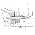
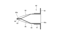
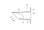
- FIG. 2 is a cross-sectional view of the vicinity of the drainage structure in the vehicle air conditioner.
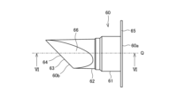
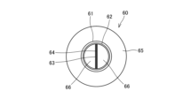
- FIG. 3 is a front view of a drainage part in the drainage structure. 4 is a left side view in FIG. 3.
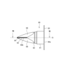
- FIG. 5 is a bottom view in FIG. 3.
- FIG. 6 is a sectional view taken along line VI-VI in FIG. 3.
- FIG. FIG. 7 is a cross-sectional view taken along line VII-VII in FIG.
- drainage structure 100 a vehicle air conditioner drainage structure (hereinafter simply referred to as “drainage structure”) 100 according to an embodiment of the present invention is applied will be described with reference to the drawings.
- FIG. 1 is an exploded perspective view of essential parts of a vehicle 1 to which a drainage structure 100 is applied.
- FIG. 2 is a cross-sectional view of the vicinity of the drainage structure 100 in the vehicle 1.
- the X-axis is the vehicle length direction (front-rear direction)
- the Y-axis is the vehicle width direction (left-right direction)
- the Z-axis is the vehicle height direction (vertical direction).
- the X-axis, Y-axis and Z-axis are orthogonal to each other.
- a vehicle 1 includes an engine room (motor room in the case of an electric vehicle) 2 as a drive source room, a passenger compartment 3, a partition wall 4, and a vehicle air conditioner (hereinafter simply referred to as "air conditioner”). device”) 5 and a cover 30.
- engine room motor room in the case of an electric vehicle
- passenger compartment passenger compartment 3
- partition wall 4 partition wall 4
- air conditioner vehicle air conditioner
- the engine room 2 is provided in the front part of the vehicle 1.
- the engine room 2 accommodates an engine (not shown), an electric motor (not shown), etc. as a drive source for driving the drive wheels (not shown) of the vehicle 1 .
- the vehicle compartment 3 is provided behind the engine room 2. That is, the engine room 2 and the passenger compartment 3 are arranged side by side in the longitudinal direction of the vehicle 1 . An occupant rides in the passenger compartment 3 .
- the partition wall 4 separates the engine room 2 and the vehicle compartment 3. That is, the partition wall 4 separates the inside and outside of the compartment 3 .
- the partition wall 4 prevents noise in the engine room 2 and noise outside the vehicle 1 from entering the vehicle interior 3 .
- the partition wall 4 is provided with a through portion 4a.
- the air conditioner 5 has a HVAC (Heating Ventilation and Air Conditioning) unit 6, a refrigeration cycle circuit 10 (see FIG. 2), and a drainage structure 100.
- HVAC Heating Ventilation and Air Conditioning
- the air used for air conditioning passes through the HVAC unit 6.
- the HVAC unit 6 has a case 7 , an air conditioner body 8 , an inside/outside air switching device 9 , and a blower 23 .
- the HVAC unit 6 has all the components arranged in the front part (rear part of the bulkhead 4) inside the passenger compartment 3, and is covered from above by an instrument panel (not shown). , are hidden so as not to be seen by the occupants in the passenger compartment 3 .
- the HVAC unit 6 is divided into the engine room 2 and the passenger compartment 3 , which are connected through the through portion 4 a of the partition wall 4 .
- a blower 23 and an evaporator 11 (see FIG. 2), which will be described later, of the refrigeration cycle circuit 10 are provided in the engine room 2, and other components such as the inside/outside air switching device 9 are installed. It is provided in the vehicle interior 3 .
- some of the components are arranged inside the engine room 2 to widen the space inside the vehicle compartment 3 .
- the case 7 accommodates the blower 23 and the evaporator 11 (see FIG. 2).
- the case 7 defines an internal space through which air used for air conditioning passes.
- the blower 23 is rotationally driven by an electric motor (not shown).
- the air blower 23 draws the air inside the vehicle interior 3 and the outside air into the HVAC unit 6 .
- the air conditioner body 8 has a front portion 8a and a rear portion 8b.
- the front portion 8a is arranged inside the engine room 2 .
- An evaporator 11 is accommodated in the front portion 8a.
- the rear portion 8b is housed inside the vehicle compartment 3 .
- the rear portion 8b is provided with an outlet switching device (not shown) for switching which outlet in the cabin 3 air is to be blown out.
- the inside/outside air switching device 9 has an inside air intake port 9a, an outside air intake port 9b, and a filter 53.
- the air inside the vehicle interior 3 is taken in through the inside air intake port 9a.
- Air (outside air) outside the vehicle 1 is taken in from the outside air intake port 9b.
- the inside/outside air switching device 9 switches between the inside air intake port 9a and the outside air intake port 9b to take in air.
- the filter 53 is detachably attached inside the inside/outside air switching device 9 .
- the filter 53 removes particles from the air taken into the HVAC unit 6 by the blower 23 to purify the air.
- the refrigeration cycle circuit 10 has a compressor (not shown), a condenser (not shown), an expansion valve (not shown), and an evaporator 11 .
- the compressor compresses the gas-phase refrigerant to high temperature and pressure
- the condenser exchanges heat with the outside air to condense and liquefy the refrigerant
- the expansion valve decompresses and expands the liquid-phase refrigerant.
- the evaporator 11 evaporates the refrigerant through heat exchange with the air used for air conditioning.
- the evaporator 11 is provided within the HVAC unit 6, and cools and dehumidifies the air supplied to the vehicle interior 3 by heat exchange with the refrigerant. Therefore, condensed water is generated on the surface of the evaporator 11 by condensing water vapor in the air. In order to discharge this condensed water to the outside, the air conditioner 5 is provided with a drainage structure 100 .
- the drainage structure 100 includes a drain pipe 50.
- the drain pipe 50 extends along the mounting direction of the cover body 31, which will be described later.
- the drain pipe 50 discharges the condensed water generated in the evaporator 11 to the outside.
- the direction opposite to the "attachment direction” of the cover body 31 is referred to as the “extension direction", which is the direction in which the drain pipe 50 extends.
- the drain pipe 50 has an inclined portion 63 provided at the tip and inclined gradually upward along the extending direction from the lower end portion.
- the drain pipe 50 has a guide portion 51 and a drain plug 60 .
- the guide part 51 is formed in a cylindrical shape.
- a condensed water passage 52 through which condensed water passes is formed on the inner periphery of the guide portion 51 .
- the guide portion 51 communicates the inside and the outside of the case 7 in the extending direction.
- the guide portion 51 guides the condensed water generated in the evaporator 11 in the extending direction.
- the drainage plug 60 is attached to the tip of the guide portion 51 .
- a slit 64 is provided in the drain plug 60 .
- FIG. 2 shows the horizontal plane P and the centerline Q of the drain pipe 50 (drainage plug 60).
- the center line Q extends in the same direction as the mounting direction (extending direction).
- the drain pipe 50 has a first predetermined angle with respect to the horizontal plane P so that the tip end portion 50b provided with the slit 64 is positioned below the base end portion 50a to which the condensed water generated in the evaporator 11 is supplied. It is provided with an inclination of ⁇ [deg].
- the slit 64 is provided so as to be inclined with respect to the horizontal plane P by an angle ⁇ [deg] as a second predetermined angle.
- the angle ⁇ is, for example, 5 [deg]
- the angle ⁇ is, for example, 40 [deg].
- angle ⁇ is greater than angle ⁇ .
- the cover 30 is provided inside the engine room 2 and attached to the partition wall 4 .
- the cover 30 is attached along the attachment direction (see FIG. 2) from the front to the rear of the passenger compartment 3 .
- the cover 30 accommodates components of the air conditioner 5 arranged in the engine room 2 such as the blower 23 and the evaporator 11 .
- the cover 30 covers the through portion 4a formed in the partition wall 4 so as to completely hide it.
- the cover 30 prevents noise in the engine room 2 and noise outside the vehicle 1 from entering the vehicle interior 3 through the through portion 4a.
- the cover 30 has a cover body 31 and a lid portion 32 .
- the cover body 31 has an upper opening 31a and an insertion hole 33 as an opening.
- the upper opening 31 a opens to the upper part of the cover body 31 inside the engine room 2 . Since the blower 23 can be accessed from above the cover 30 by providing the upper opening 31a, the maintenance of the blower 23 can be facilitated.
- the insertion hole 33 has a circular opening on the front surface of the cover body 31 .
- the insertion hole 33 communicates the inside and the outside of the cover 30 in the extending direction.
- a drain plug 60 of the drain pipe 50 is inserted through the insertion hole 33 .
- the drain pipe 50 is provided, which is inserted through the cover 30 and extends in the mounting direction of the cover 30 to discharge the condensed water to the outside. Therefore, when attaching the cover 30 to the partition wall 4, it is necessary to insert the drain pipe 50 through the cover 30, but the cover 30 may be provided with an insertion hole 33 large enough for the drain pipe 50 to be inserted. Therefore, the insertion hole 33 provided in the cover 30 can be made smaller. Therefore, even when the evaporator 11 is provided in the engine room 2 and the cover 30 is provided with the insertion hole 33 for discharging the condensed water to the outside, the intrusion of outside noise into the passenger compartment 3 is suppressed. be able to.
- the lid portion 32 closes the upper opening portion 31a of the cover body 31 from above.
- the lid portion 32 has an inclined portion 34 that is inclined downward toward the front.
- the partition wall 4 has a through portion 4a, but when the lid portion 32 is attached, the partition wall 4, the cover main body 31, and the lid portion 32 completely isolate the engine compartment 2 and the vehicle compartment 3 from each other. be.
- FIG. 3 is a front view of the drain plug 60 in the drain structure 100.
- FIG. 4 is a left side view in FIG. 3.
- FIG. 5 is a bottom view in FIG. 3.
- FIG. 6 is a sectional view taken along line VI-VI in FIG. 3.
- FIG. 7 is a cross-sectional view taken along line VII-VII in FIG.
- the drainage plug 60 has a straight tube portion 61 , a drainage portion 62 , an inclined portion 63 , a slit 64 , a flange portion 65 and an inclined surface 66 .
- a base end portion 60 a of the drain plug 60 is attached to the straight pipe portion 61 .
- the tip portion 60b of the drain plug 60 constitutes the tip portion 50b of the drain pipe 50 (see FIG. 2).
- the drain plug 60 is made of elastic elastomer such as rubber or resin.
- the straight pipe portion 61 is provided at the base end portion 60 a of the drain plug 60 .
- the straight pipe portion 61 has a circular cross-sectional shape.
- the straight pipe portion 61 is fitted around the outer periphery of the guide portion 51 .
- the drainage portion 62 is formed continuously from the straight tube portion 61 to the tip portion 60b side of the drainage plug 60.
- the drainage portion 62 protrudes from the guide portion 51 toward the front of the vehicle 1 (see FIG. 2).
- the drainage portion 62 is formed to have a thickness smaller than that of the straight pipe portion 61 .
- the drainage part 62 is formed with a thickness of 0.5 [mm], for example. Therefore, the drainage portion 62 is more easily deformed than the straight pipe portion 61 when water pressure acts from the outside.
- the drainage portion 62 is provided with an inclined portion 63 , a slit 64 and an inclined surface 66 .
- the inclined portion 63 is provided at the tip of the drainage portion 62 .
- the inclined portion 63 is linearly inclined so as to gradually go upward along the extending direction from the lower end portion.
- the slit 64 is formed in the center of the drainage part 62 in the horizontal direction along the vertical direction.
- a slit 64 is provided in the inclined portion 63 .
- the slit 64 is formed so as to be gradually inclined upward along the extending direction from the lower end.
- the slit 64 does not have an opening width and is not open in a normal state.
- the drainage structure 100 has the drain pipe 50 that extends in the mounting direction (front-rear direction) of the cover 30 through the cover 30 to discharge condensed water to the outside. Therefore, compared with the case where the drain pipe extends vertically, for example, the condensed water is less likely to be discharged.
- the drain pipe 50 is provided with a slit 64 extending obliquely upward from the lower end along the extending direction. Therefore, the pressure of the water accumulated in the drain pipe 50 acts on the lower region of the slit 64, and when a predetermined amount of condensed water accumulates, the slit 64 opens due to the pressure of the condensed water. Therefore, even when the drain pipe 50 extends in the mounting direction (front-rear direction) of the cover 30, it is possible to ensure drainage of condensed water.
- the flange portion 65 is provided at the base end portion 60 a of the drain plug 60 .
- the flange portion 65 is formed so as to increase in diameter from the entire outer circumference of the straight pipe portion 61 toward the outer circumference.
- the flange portion 65 is sandwiched between the case 7 of the HVAC unit 6 and the cover 30 (see FIG. 2). As a result, the gap between the outer periphery of the straight pipe portion 61 of the drain plug 60 and the inner periphery of the insertion hole 33 of the cover body 31 is sealed. Therefore, the engine room 2 and the passenger compartment 3 can be completely isolated.
- the inclined surfaces 66 are provided on the left and right sides of the slit 64, respectively.
- the inclined surfaces 66 are a pair of flat surfaces that are inclined toward the slit 64 from the circular cross-sectional portion of the drainage portion 62 . Since the inclined surface 66 is provided, when the drain plug 60 is submerged in water, water pressure acts on the inclined surface 66 and a force acts in the direction to close the slit 64 . Therefore, even if the drain plug 60 is submerged in water, water is prevented from entering the drain plug 60 through the slit 64 .
- a partition 4 that separates the inside and outside of the vehicle interior 3 in which the occupant rides, an evaporator 11 that is arranged outside the partition 4 with respect to the vehicle interior 3 and cools the air supplied to the vehicle interior 3 by heat exchange with the refrigerant,
- a drainage structure 100 for an air conditioner 5 of a vehicle 1 including a cover 30 that is attached to the partition wall 4 from the front of the vehicle compartment 3 and that houses the evaporator 11 extends in the mounting direction of the cover 30 by inserting the cover 30. and a drain pipe 50 for discharging condensed water generated in the evaporator 11 to the outside, and the drain pipe 50 has a slit 64 which is inclined upward along the extending direction from the lower end portion thereof. .
- a drain pipe 50 is provided that penetrates the cover 30 and extends in the mounting direction of the cover 30 to discharge condensed water to the outside. Therefore, when attaching the cover 30 to the partition wall 4, it is necessary to insert the drain pipe 50 through the cover 30, but the cover 30 may be provided with an insertion hole 33 large enough for the drain pipe 50 to be inserted. Therefore, even if the evaporator 11 is provided outside the partition wall 4 with respect to the passenger compartment 3 and the cover 30 is provided with the insertion hole 33 for discharging the condensed water to the outside, the outside noise will not enter the passenger compartment 3. Intrusion can be suppressed.
- the drain pipe 50 is provided with a slit 64 extending obliquely upward from the lower end along the extending direction. Therefore, the pressure of the water accumulated in the drain pipe 50 acts on the lower region of the slit 64, and when a predetermined amount of condensed water accumulates, the slit 64 opens due to the pressure of the condensed water. Therefore, even when the drain pipe 50 extends in the mounting direction (front-rear direction) of the cover 30, it is possible to ensure drainage of condensed water.
Landscapes
- Engineering & Computer Science (AREA)
- Mechanical Engineering (AREA)
- Physics & Mathematics (AREA)
- Thermal Sciences (AREA)
- Chemical & Material Sciences (AREA)
- Combustion & Propulsion (AREA)
- General Engineering & Computer Science (AREA)
- Air-Conditioning For Vehicles (AREA)
Priority Applications (2)
| Application Number | Priority Date | Filing Date | Title |
|---|---|---|---|
| US18/711,943 US20250018772A1 (en) | 2021-11-24 | 2022-11-02 | Drainage structure for vehicle air-conditioning device |
| CN202280077401.XA CN118382548A (zh) | 2021-11-24 | 2022-11-02 | 车辆用空调装置的排水构造 |
Applications Claiming Priority (2)
| Application Number | Priority Date | Filing Date | Title |
|---|---|---|---|
| JP2021190302A JP2023077133A (ja) | 2021-11-24 | 2021-11-24 | 車両用空調装置の排水構造 |
| JP2021-190302 | 2021-11-24 |
Publications (1)
| Publication Number | Publication Date |
|---|---|
| WO2023095585A1 true WO2023095585A1 (ja) | 2023-06-01 |
Family
ID=86539339
Family Applications (1)
| Application Number | Title | Priority Date | Filing Date |
|---|---|---|---|
| PCT/JP2022/041046 Ceased WO2023095585A1 (ja) | 2021-11-24 | 2022-11-02 | 車両用空調装置の排水構造 |
Country Status (4)
| Country | Link |
|---|---|
| US (1) | US20250018772A1 (enExample) |
| JP (1) | JP2023077133A (enExample) |
| CN (1) | CN118382548A (enExample) |
| WO (1) | WO2023095585A1 (enExample) |
Cited By (1)
| Publication number | Priority date | Publication date | Assignee | Title |
|---|---|---|---|---|
| DE102024204523A1 (de) * | 2024-05-16 | 2025-11-20 | Volkswagen Aktiengesellschaft | Klimaanlagensystem für ein Kraftfahrzeug |
Citations (4)
| Publication number | Priority date | Publication date | Assignee | Title |
|---|---|---|---|---|
| JPH0271076A (ja) * | 1988-09-07 | 1990-03-09 | Osaka Shosen Mitsui Senpaku Kk | コンテナ用冷凍装置 |
| JPH10324146A (ja) * | 1997-05-26 | 1998-12-08 | Zexel Corp | 車両パネルに形成のドレンパイプ及びヒータパイプ貫通穴のシール装置 |
| JPH11107949A (ja) * | 1997-10-06 | 1999-04-20 | Matsushita Electric Ind Co Ltd | スクロール圧縮機 |
| JPH11132639A (ja) * | 1997-10-31 | 1999-05-21 | Sanyo Electric Co Ltd | 冷蔵庫 |
Family Cites Families (10)
| Publication number | Priority date | Publication date | Assignee | Title |
|---|---|---|---|---|
| KR19980030821U (ko) * | 1996-11-29 | 1998-08-17 | 양재신 | 에어컨의 드레인 호스 |
| JP2005170303A (ja) * | 2003-12-12 | 2005-06-30 | Denso Corp | 車両用空調装置 |
| WO2008144951A1 (de) * | 2007-05-31 | 2008-12-04 | Medela Holding Ag | Drainagevorrichtung |
| CN102967041A (zh) * | 2012-11-30 | 2013-03-13 | 芜湖博耐尔汽车电气系统有限公司 | 一种汽车空调排水管结构 |
| KR101666565B1 (ko) * | 2013-08-20 | 2016-10-14 | 한온시스템 주식회사 | 차량용 공조장치 |
| CN107199848A (zh) * | 2017-07-20 | 2017-09-26 | 艾泰斯热系统研发(上海)有限公司 | 分体式电动汽车空调器 |
| JP6977636B2 (ja) * | 2018-03-15 | 2021-12-08 | 株式会社デンソー | 空調装置 |
| CN112135742B (zh) * | 2018-05-17 | 2024-02-13 | 马瑞利(中国)汽车空调有限公司 | 车辆用空调装置 |
| CN210861525U (zh) * | 2019-10-30 | 2020-06-26 | 北京彩云归科技有限公司 | 加湿器 |
| KR102730224B1 (ko) * | 2020-06-30 | 2024-11-14 | 한온시스템 주식회사 | 차량용 공조장치 |
-
2021
- 2021-11-24 JP JP2021190302A patent/JP2023077133A/ja active Pending
-
2022
- 2022-11-02 WO PCT/JP2022/041046 patent/WO2023095585A1/ja not_active Ceased
- 2022-11-02 CN CN202280077401.XA patent/CN118382548A/zh active Pending
- 2022-11-02 US US18/711,943 patent/US20250018772A1/en active Pending
Patent Citations (4)
| Publication number | Priority date | Publication date | Assignee | Title |
|---|---|---|---|---|
| JPH0271076A (ja) * | 1988-09-07 | 1990-03-09 | Osaka Shosen Mitsui Senpaku Kk | コンテナ用冷凍装置 |
| JPH10324146A (ja) * | 1997-05-26 | 1998-12-08 | Zexel Corp | 車両パネルに形成のドレンパイプ及びヒータパイプ貫通穴のシール装置 |
| JPH11107949A (ja) * | 1997-10-06 | 1999-04-20 | Matsushita Electric Ind Co Ltd | スクロール圧縮機 |
| JPH11132639A (ja) * | 1997-10-31 | 1999-05-21 | Sanyo Electric Co Ltd | 冷蔵庫 |
Cited By (1)
| Publication number | Priority date | Publication date | Assignee | Title |
|---|---|---|---|---|
| DE102024204523A1 (de) * | 2024-05-16 | 2025-11-20 | Volkswagen Aktiengesellschaft | Klimaanlagensystem für ein Kraftfahrzeug |
Also Published As
| Publication number | Publication date |
|---|---|
| US20250018772A1 (en) | 2025-01-16 |
| JP2023077133A (ja) | 2023-06-05 |
| CN118382548A (zh) | 2024-07-23 |
Similar Documents
| Publication | Publication Date | Title |
|---|---|---|
| KR20100115342A (ko) | 차량 캐빈용 공조시스템과 이를 수용하는 모듈 | |
| EP0889295B1 (en) | Recreational vehicle refrigerator with combustion seal and heat deflector and recreational vehicle with refrigerator | |
| WO2023095585A1 (ja) | 車両用空調装置の排水構造 | |
| JP2008126800A (ja) | 自動車用空調装置 | |
| JP2000219029A (ja) | キャビン | |
| US20080216502A1 (en) | Air conditioning case and drain for condensate removal | |
| JP2006525187A (ja) | ルーフトップ空調ユニット用の凝縮水ポンプ | |
| JPH09193648A (ja) | 空調ユニット | |
| KR20160091227A (ko) | 냉난방 모듈 | |
| JP4016690B2 (ja) | 車両用空調装置 | |
| JP2011157002A (ja) | 車両用空調装置の排水構造 | |
| JP7705840B2 (ja) | 車両用空調装置のカバー構造 | |
| JP3344208B2 (ja) | 車両用天井置きクーラユニット | |
| JP2020032775A (ja) | 車両用空調装置の排水構造 | |
| JP3890993B2 (ja) | 車両用空調装置 | |
| JP3111894B2 (ja) | 車両用空調装置 | |
| KR20090022499A (ko) | 센터 마운팅 타입 차량 공조장치의 증발기 파이프 설치구조 | |
| JP4624869B2 (ja) | 車両用空調装置 | |
| JP4957437B2 (ja) | 車両用空調装置の空調ユニット | |
| JP2002046447A (ja) | 車両用空気調和ユニット | |
| JP5508040B2 (ja) | 車両用空調装置 | |
| JP2004196117A (ja) | 車両用空調ユニット | |
| JPH082244A (ja) | 車両用空調装置 | |
| JP2007313986A (ja) | 車両用空調ユニットの取付構造 | |
| JP4468265B2 (ja) | フィルターユニットおよび空調装置 |
Legal Events
| Date | Code | Title | Description |
|---|---|---|---|
| 121 | Ep: the epo has been informed by wipo that ep was designated in this application |
Ref document number: 22898369 Country of ref document: EP Kind code of ref document: A1 |
|
| WWE | Wipo information: entry into national phase |
Ref document number: 18711943 Country of ref document: US |
|
| WWE | Wipo information: entry into national phase |
Ref document number: 202280077401.X Country of ref document: CN |
|
| NENP | Non-entry into the national phase |
Ref country code: DE |
|
| 122 | Ep: pct application non-entry in european phase |
Ref document number: 22898369 Country of ref document: EP Kind code of ref document: A1 |