WO2023095585A1 - Drainage structure for vehicle air conditioner - Google Patents
Drainage structure for vehicle air conditioner Download PDFInfo
- Publication number
- WO2023095585A1 WO2023095585A1 PCT/JP2022/041046 JP2022041046W WO2023095585A1 WO 2023095585 A1 WO2023095585 A1 WO 2023095585A1 JP 2022041046 W JP2022041046 W JP 2022041046W WO 2023095585 A1 WO2023095585 A1 WO 2023095585A1
- Authority
- WO
- WIPO (PCT)
- Prior art keywords
- drainage structure
- vehicle air
- cover
- evaporator
- slit
- Prior art date
Links
Images

Classifications
-
- B—PERFORMING OPERATIONS; TRANSPORTING
- B60—VEHICLES IN GENERAL
- B60H—ARRANGEMENTS OF HEATING, COOLING, VENTILATING OR OTHER AIR-TREATING DEVICES SPECIALLY ADAPTED FOR PASSENGER OR GOODS SPACES OF VEHICLES
- B60H1/00—Heating, cooling or ventilating [HVAC] devices
- B60H1/32—Cooling devices
-
- F—MECHANICAL ENGINEERING; LIGHTING; HEATING; WEAPONS; BLASTING
- F24—HEATING; RANGES; VENTILATING
- F24F—AIR-CONDITIONING; AIR-HUMIDIFICATION; VENTILATION; USE OF AIR CURRENTS FOR SCREENING
- F24F13/00—Details common to, or for air-conditioning, air-humidification, ventilation or use of air currents for screening
- F24F13/22—Means for preventing condensation or evacuating condensate
Definitions
- the present invention relates to a drainage structure for a vehicle air conditioner.
- JP2019-202755A some of the component parts of a vehicle air conditioner, such as a blower and an evaporator, are placed in an engine room that is separated from the vehicle compartment by a bulkhead in order to expand the space in the vehicle compartment, and the component parts are accommodated.
- a vehicular air conditioner has been disclosed in which a cover is provided to prevent external noise from entering the vehicle interior.
- the present invention suppresses external noise from entering the vehicle interior even when the evaporator is provided outside the partition wall for the vehicle interior and the cover is provided with an opening for discharging condensed water to the outside. With the goal.
- a partition wall that separates the inside and outside of a vehicle interior in which a passenger rides, and a partition wall that is disposed outside the partition wall with respect to the vehicle interior and cools air supplied to the vehicle interior by heat exchange with a refrigerant. and a cover that is attached to the partition wall from the front of the passenger compartment and accommodates the evaporator. and a drain pipe for discharging condensed water generated in the evaporator to the outside, and the drain pipe has a slit inclined upward along the extending direction from the lower end of the drain pipe.
- the drain pipe is provided to extend in the mounting direction of the cover through the cover and discharge condensed water to the outside, and the drain pipe is inclined obliquely upward from the lower end along the extending direction. It has a slit that Therefore, when attaching the cover to the partition wall, it is necessary to insert the drain pipe into the cover. Therefore, even when the evaporator is provided outside the partition wall for the passenger compartment and the cover is provided with an opening for discharging the condensed water to the outside, it is possible to suppress the intrusion of outside noise into the passenger compartment. .
- FIG. 1 is an exploded perspective view of the essential parts of a vehicle to which a drainage structure according to an embodiment of the invention is applied.
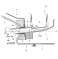
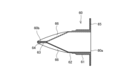
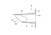
- FIG. 2 is a cross-sectional view of the vicinity of the drainage structure in the vehicle air conditioner.
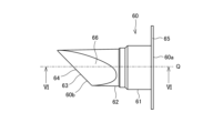
- FIG. 3 is a front view of a drainage part in the drainage structure. 4 is a left side view in FIG. 3.
- FIG. 5 is a bottom view in FIG. 3.
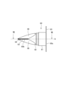
- FIG. 6 is a sectional view taken along line VI-VI in FIG. 3.
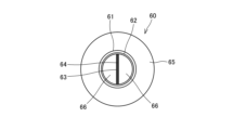
- FIG. FIG. 7 is a cross-sectional view taken along line VII-VII in FIG.
- drainage structure 100 a vehicle air conditioner drainage structure (hereinafter simply referred to as “drainage structure”) 100 according to an embodiment of the present invention is applied will be described with reference to the drawings.
- FIG. 1 is an exploded perspective view of essential parts of a vehicle 1 to which a drainage structure 100 is applied.
- FIG. 2 is a cross-sectional view of the vicinity of the drainage structure 100 in the vehicle 1.
- the X-axis is the vehicle length direction (front-rear direction)
- the Y-axis is the vehicle width direction (left-right direction)
- the Z-axis is the vehicle height direction (vertical direction).
- the X-axis, Y-axis and Z-axis are orthogonal to each other.
- a vehicle 1 includes an engine room (motor room in the case of an electric vehicle) 2 as a drive source room, a passenger compartment 3, a partition wall 4, and a vehicle air conditioner (hereinafter simply referred to as "air conditioner”). device”) 5 and a cover 30.
- engine room motor room in the case of an electric vehicle
- passenger compartment passenger compartment 3
- partition wall 4 partition wall 4
- air conditioner vehicle air conditioner
- the engine room 2 is provided in the front part of the vehicle 1.
- the engine room 2 accommodates an engine (not shown), an electric motor (not shown), etc. as a drive source for driving the drive wheels (not shown) of the vehicle 1 .
- the vehicle compartment 3 is provided behind the engine room 2. That is, the engine room 2 and the passenger compartment 3 are arranged side by side in the longitudinal direction of the vehicle 1 . An occupant rides in the passenger compartment 3 .
- the partition wall 4 separates the engine room 2 and the vehicle compartment 3. That is, the partition wall 4 separates the inside and outside of the compartment 3 .
- the partition wall 4 prevents noise in the engine room 2 and noise outside the vehicle 1 from entering the vehicle interior 3 .
- the partition wall 4 is provided with a through portion 4a.
- the air conditioner 5 has a HVAC (Heating Ventilation and Air Conditioning) unit 6, a refrigeration cycle circuit 10 (see FIG. 2), and a drainage structure 100.
- HVAC Heating Ventilation and Air Conditioning
- the air used for air conditioning passes through the HVAC unit 6.
- the HVAC unit 6 has a case 7 , an air conditioner body 8 , an inside/outside air switching device 9 , and a blower 23 .
- the HVAC unit 6 has all the components arranged in the front part (rear part of the bulkhead 4) inside the passenger compartment 3, and is covered from above by an instrument panel (not shown). , are hidden so as not to be seen by the occupants in the passenger compartment 3 .
- the HVAC unit 6 is divided into the engine room 2 and the passenger compartment 3 , which are connected through the through portion 4 a of the partition wall 4 .
- a blower 23 and an evaporator 11 (see FIG. 2), which will be described later, of the refrigeration cycle circuit 10 are provided in the engine room 2, and other components such as the inside/outside air switching device 9 are installed. It is provided in the vehicle interior 3 .
- some of the components are arranged inside the engine room 2 to widen the space inside the vehicle compartment 3 .
- the case 7 accommodates the blower 23 and the evaporator 11 (see FIG. 2).
- the case 7 defines an internal space through which air used for air conditioning passes.
- the blower 23 is rotationally driven by an electric motor (not shown).
- the air blower 23 draws the air inside the vehicle interior 3 and the outside air into the HVAC unit 6 .
- the air conditioner body 8 has a front portion 8a and a rear portion 8b.
- the front portion 8a is arranged inside the engine room 2 .
- An evaporator 11 is accommodated in the front portion 8a.
- the rear portion 8b is housed inside the vehicle compartment 3 .
- the rear portion 8b is provided with an outlet switching device (not shown) for switching which outlet in the cabin 3 air is to be blown out.
- the inside/outside air switching device 9 has an inside air intake port 9a, an outside air intake port 9b, and a filter 53.
- the air inside the vehicle interior 3 is taken in through the inside air intake port 9a.
- Air (outside air) outside the vehicle 1 is taken in from the outside air intake port 9b.
- the inside/outside air switching device 9 switches between the inside air intake port 9a and the outside air intake port 9b to take in air.
- the filter 53 is detachably attached inside the inside/outside air switching device 9 .
- the filter 53 removes particles from the air taken into the HVAC unit 6 by the blower 23 to purify the air.
- the refrigeration cycle circuit 10 has a compressor (not shown), a condenser (not shown), an expansion valve (not shown), and an evaporator 11 .
- the compressor compresses the gas-phase refrigerant to high temperature and pressure
- the condenser exchanges heat with the outside air to condense and liquefy the refrigerant
- the expansion valve decompresses and expands the liquid-phase refrigerant.
- the evaporator 11 evaporates the refrigerant through heat exchange with the air used for air conditioning.
- the evaporator 11 is provided within the HVAC unit 6, and cools and dehumidifies the air supplied to the vehicle interior 3 by heat exchange with the refrigerant. Therefore, condensed water is generated on the surface of the evaporator 11 by condensing water vapor in the air. In order to discharge this condensed water to the outside, the air conditioner 5 is provided with a drainage structure 100 .
- the drainage structure 100 includes a drain pipe 50.
- the drain pipe 50 extends along the mounting direction of the cover body 31, which will be described later.
- the drain pipe 50 discharges the condensed water generated in the evaporator 11 to the outside.
- the direction opposite to the "attachment direction” of the cover body 31 is referred to as the “extension direction", which is the direction in which the drain pipe 50 extends.
- the drain pipe 50 has an inclined portion 63 provided at the tip and inclined gradually upward along the extending direction from the lower end portion.
- the drain pipe 50 has a guide portion 51 and a drain plug 60 .
- the guide part 51 is formed in a cylindrical shape.
- a condensed water passage 52 through which condensed water passes is formed on the inner periphery of the guide portion 51 .
- the guide portion 51 communicates the inside and the outside of the case 7 in the extending direction.
- the guide portion 51 guides the condensed water generated in the evaporator 11 in the extending direction.
- the drainage plug 60 is attached to the tip of the guide portion 51 .
- a slit 64 is provided in the drain plug 60 .
- FIG. 2 shows the horizontal plane P and the centerline Q of the drain pipe 50 (drainage plug 60).
- the center line Q extends in the same direction as the mounting direction (extending direction).
- the drain pipe 50 has a first predetermined angle with respect to the horizontal plane P so that the tip end portion 50b provided with the slit 64 is positioned below the base end portion 50a to which the condensed water generated in the evaporator 11 is supplied. It is provided with an inclination of ⁇ [deg].
- the slit 64 is provided so as to be inclined with respect to the horizontal plane P by an angle ⁇ [deg] as a second predetermined angle.
- the angle ⁇ is, for example, 5 [deg]
- the angle ⁇ is, for example, 40 [deg].
- angle ⁇ is greater than angle ⁇ .
- the cover 30 is provided inside the engine room 2 and attached to the partition wall 4 .
- the cover 30 is attached along the attachment direction (see FIG. 2) from the front to the rear of the passenger compartment 3 .
- the cover 30 accommodates components of the air conditioner 5 arranged in the engine room 2 such as the blower 23 and the evaporator 11 .
- the cover 30 covers the through portion 4a formed in the partition wall 4 so as to completely hide it.
- the cover 30 prevents noise in the engine room 2 and noise outside the vehicle 1 from entering the vehicle interior 3 through the through portion 4a.
- the cover 30 has a cover body 31 and a lid portion 32 .
- the cover body 31 has an upper opening 31a and an insertion hole 33 as an opening.
- the upper opening 31 a opens to the upper part of the cover body 31 inside the engine room 2 . Since the blower 23 can be accessed from above the cover 30 by providing the upper opening 31a, the maintenance of the blower 23 can be facilitated.
- the insertion hole 33 has a circular opening on the front surface of the cover body 31 .
- the insertion hole 33 communicates the inside and the outside of the cover 30 in the extending direction.
- a drain plug 60 of the drain pipe 50 is inserted through the insertion hole 33 .
- the drain pipe 50 is provided, which is inserted through the cover 30 and extends in the mounting direction of the cover 30 to discharge the condensed water to the outside. Therefore, when attaching the cover 30 to the partition wall 4, it is necessary to insert the drain pipe 50 through the cover 30, but the cover 30 may be provided with an insertion hole 33 large enough for the drain pipe 50 to be inserted. Therefore, the insertion hole 33 provided in the cover 30 can be made smaller. Therefore, even when the evaporator 11 is provided in the engine room 2 and the cover 30 is provided with the insertion hole 33 for discharging the condensed water to the outside, the intrusion of outside noise into the passenger compartment 3 is suppressed. be able to.
- the lid portion 32 closes the upper opening portion 31a of the cover body 31 from above.
- the lid portion 32 has an inclined portion 34 that is inclined downward toward the front.
- the partition wall 4 has a through portion 4a, but when the lid portion 32 is attached, the partition wall 4, the cover main body 31, and the lid portion 32 completely isolate the engine compartment 2 and the vehicle compartment 3 from each other. be.
- FIG. 3 is a front view of the drain plug 60 in the drain structure 100.
- FIG. 4 is a left side view in FIG. 3.
- FIG. 5 is a bottom view in FIG. 3.
- FIG. 6 is a sectional view taken along line VI-VI in FIG. 3.
- FIG. 7 is a cross-sectional view taken along line VII-VII in FIG.
- the drainage plug 60 has a straight tube portion 61 , a drainage portion 62 , an inclined portion 63 , a slit 64 , a flange portion 65 and an inclined surface 66 .
- a base end portion 60 a of the drain plug 60 is attached to the straight pipe portion 61 .
- the tip portion 60b of the drain plug 60 constitutes the tip portion 50b of the drain pipe 50 (see FIG. 2).
- the drain plug 60 is made of elastic elastomer such as rubber or resin.
- the straight pipe portion 61 is provided at the base end portion 60 a of the drain plug 60 .
- the straight pipe portion 61 has a circular cross-sectional shape.
- the straight pipe portion 61 is fitted around the outer periphery of the guide portion 51 .
- the drainage portion 62 is formed continuously from the straight tube portion 61 to the tip portion 60b side of the drainage plug 60.
- the drainage portion 62 protrudes from the guide portion 51 toward the front of the vehicle 1 (see FIG. 2).
- the drainage portion 62 is formed to have a thickness smaller than that of the straight pipe portion 61 .
- the drainage part 62 is formed with a thickness of 0.5 [mm], for example. Therefore, the drainage portion 62 is more easily deformed than the straight pipe portion 61 when water pressure acts from the outside.
- the drainage portion 62 is provided with an inclined portion 63 , a slit 64 and an inclined surface 66 .
- the inclined portion 63 is provided at the tip of the drainage portion 62 .
- the inclined portion 63 is linearly inclined so as to gradually go upward along the extending direction from the lower end portion.
- the slit 64 is formed in the center of the drainage part 62 in the horizontal direction along the vertical direction.
- a slit 64 is provided in the inclined portion 63 .
- the slit 64 is formed so as to be gradually inclined upward along the extending direction from the lower end.
- the slit 64 does not have an opening width and is not open in a normal state.
- the drainage structure 100 has the drain pipe 50 that extends in the mounting direction (front-rear direction) of the cover 30 through the cover 30 to discharge condensed water to the outside. Therefore, compared with the case where the drain pipe extends vertically, for example, the condensed water is less likely to be discharged.
- the drain pipe 50 is provided with a slit 64 extending obliquely upward from the lower end along the extending direction. Therefore, the pressure of the water accumulated in the drain pipe 50 acts on the lower region of the slit 64, and when a predetermined amount of condensed water accumulates, the slit 64 opens due to the pressure of the condensed water. Therefore, even when the drain pipe 50 extends in the mounting direction (front-rear direction) of the cover 30, it is possible to ensure drainage of condensed water.
- the flange portion 65 is provided at the base end portion 60 a of the drain plug 60 .
- the flange portion 65 is formed so as to increase in diameter from the entire outer circumference of the straight pipe portion 61 toward the outer circumference.
- the flange portion 65 is sandwiched between the case 7 of the HVAC unit 6 and the cover 30 (see FIG. 2). As a result, the gap between the outer periphery of the straight pipe portion 61 of the drain plug 60 and the inner periphery of the insertion hole 33 of the cover body 31 is sealed. Therefore, the engine room 2 and the passenger compartment 3 can be completely isolated.
- the inclined surfaces 66 are provided on the left and right sides of the slit 64, respectively.
- the inclined surfaces 66 are a pair of flat surfaces that are inclined toward the slit 64 from the circular cross-sectional portion of the drainage portion 62 . Since the inclined surface 66 is provided, when the drain plug 60 is submerged in water, water pressure acts on the inclined surface 66 and a force acts in the direction to close the slit 64 . Therefore, even if the drain plug 60 is submerged in water, water is prevented from entering the drain plug 60 through the slit 64 .
- a partition 4 that separates the inside and outside of the vehicle interior 3 in which the occupant rides, an evaporator 11 that is arranged outside the partition 4 with respect to the vehicle interior 3 and cools the air supplied to the vehicle interior 3 by heat exchange with the refrigerant,
- a drainage structure 100 for an air conditioner 5 of a vehicle 1 including a cover 30 that is attached to the partition wall 4 from the front of the vehicle compartment 3 and that houses the evaporator 11 extends in the mounting direction of the cover 30 by inserting the cover 30. and a drain pipe 50 for discharging condensed water generated in the evaporator 11 to the outside, and the drain pipe 50 has a slit 64 which is inclined upward along the extending direction from the lower end portion thereof. .
- a drain pipe 50 is provided that penetrates the cover 30 and extends in the mounting direction of the cover 30 to discharge condensed water to the outside. Therefore, when attaching the cover 30 to the partition wall 4, it is necessary to insert the drain pipe 50 through the cover 30, but the cover 30 may be provided with an insertion hole 33 large enough for the drain pipe 50 to be inserted. Therefore, even if the evaporator 11 is provided outside the partition wall 4 with respect to the passenger compartment 3 and the cover 30 is provided with the insertion hole 33 for discharging the condensed water to the outside, the outside noise will not enter the passenger compartment 3. Intrusion can be suppressed.
- the drain pipe 50 is provided with a slit 64 extending obliquely upward from the lower end along the extending direction. Therefore, the pressure of the water accumulated in the drain pipe 50 acts on the lower region of the slit 64, and when a predetermined amount of condensed water accumulates, the slit 64 opens due to the pressure of the condensed water. Therefore, even when the drain pipe 50 extends in the mounting direction (front-rear direction) of the cover 30, it is possible to ensure drainage of condensed water.
Landscapes
- Engineering & Computer Science (AREA)
- Mechanical Engineering (AREA)
- Physics & Mathematics (AREA)
- Thermal Sciences (AREA)
- Chemical & Material Sciences (AREA)
- Combustion & Propulsion (AREA)
- General Engineering & Computer Science (AREA)
- Air-Conditioning For Vehicles (AREA)
Abstract
Provided is a drainage structure (100) for an air conditioner (5) of a vehicle (1) comprising a partition (4) separating the inside and outside of a cabin (3) occupied by an occupant, an evaporator (11) which is located on the outside of the partition (4) relative to the cabin (3) and which cools air supplied into the cabin (3) through heat exchange with a refrigerant, and a cover (30) which is mounted on the partition (4) from the front of the cabin (3) and which houses the evaporator (11), the drainage structure (100) comprising a drain pipe (50) which extends through the cover (30) in the mounting direction of the cover (30) and which discharges condensate generated in the evaporator (11) to the outside, wherein the drain pipe (50) has a slit (64) formed to slope upward along the extension direction from a lower end.
Description
本発明は、車両用空調装置の排水構造に関する。
The present invention relates to a drainage structure for a vehicle air conditioner.
JP2019-202755Aには、車室内空間を拡げるために送風機や蒸発器など車両用空調装置の構成部品の一部を車室と隔壁で仕切られたエンジンルーム内に配置し、当該構成部品を収容するカバーを設けて車外騒音が車室内に侵入することを防止する車両用空調装置が開示されている。
In JP2019-202755A, some of the component parts of a vehicle air conditioner, such as a blower and an evaporator, are placed in an engine room that is separated from the vehicle compartment by a bulkhead in order to expand the space in the vehicle compartment, and the component parts are accommodated. A vehicular air conditioner has been disclosed in which a cover is provided to prevent external noise from entering the vehicle interior.
ところで、蒸発器を、エンジンルーム等、車室に対する隔壁の外に設ける際には、蒸発器にて生じる凝縮水を外部に排出するためにカバーに開口部を設ける必要があるが、開口部を設けると当該開口部を通じて車外騒音が車室内へ侵入するおそれがある。
By the way, when the evaporator is installed outside the partition against the vehicle compartment, such as in the engine room, it is necessary to provide an opening in the cover in order to discharge the condensed water generated in the evaporator to the outside. If provided, there is a risk that external noise may enter the vehicle interior through the opening.
本発明は、蒸発器が車室に対する隔壁の外に設けられ、凝縮水を外部に排出するための開口部がカバーに設けられた場合にも、車外騒音の車室内への侵入を抑制することを目的とする。
The present invention suppresses external noise from entering the vehicle interior even when the evaporator is provided outside the partition wall for the vehicle interior and the cover is provided with an opening for discharging condensed water to the outside. With the goal.
本発明のある態様によれば、乗員が乗車する車室の内外を隔てる隔壁と、前記車室に対する前記隔壁の外に配置され、前記車室内に供給される空気を冷媒との熱交換によって冷却する蒸発器と、前記車室の前方から前記隔壁に取り付けられ、前記蒸発器を収容するカバーと、を備える車両の車両用空調装置の排水構造は、前記カバーを挿通して前記カバーの取り付け方向に延在し、前記蒸発器にて生じる凝縮水を外部に排出するドレン管を備え、前記ドレン管は、下端部から延在方向に沿って上方に向かうように傾斜して形成されるスリットを有する。
According to one aspect of the present invention, there is provided a partition wall that separates the inside and outside of a vehicle interior in which a passenger rides, and a partition wall that is disposed outside the partition wall with respect to the vehicle interior and cools air supplied to the vehicle interior by heat exchange with a refrigerant. and a cover that is attached to the partition wall from the front of the passenger compartment and accommodates the evaporator. and a drain pipe for discharging condensed water generated in the evaporator to the outside, and the drain pipe has a slit inclined upward along the extending direction from the lower end of the drain pipe. have.
上記態様では、カバーを挿通してカバーの取り付け方向に延在して凝縮水を外部に排出するドレン管が設けられ、ドレン管は、延在方向に沿って下端部から斜め上方に向かって傾斜するスリットを有する。そのため、カバーを隔壁に取り付けるときに、ドレン管をカバーに挿通させる必要があるが、カバーにはドレン管が挿通する大きさの開口部が設けられていればよい。したがって、蒸発器が車室に対する隔壁の外に設けられ、凝縮水を外部に排出するための開口部がカバーに設けられた場合にも、車外騒音の車室内への侵入を抑制することができる。
In the above aspect, the drain pipe is provided to extend in the mounting direction of the cover through the cover and discharge condensed water to the outside, and the drain pipe is inclined obliquely upward from the lower end along the extending direction. It has a slit that Therefore, when attaching the cover to the partition wall, it is necessary to insert the drain pipe into the cover. Therefore, even when the evaporator is provided outside the partition wall for the passenger compartment and the cover is provided with an opening for discharging the condensed water to the outside, it is possible to suppress the intrusion of outside noise into the passenger compartment. .
以下、図面を参照して、本発明の実施形態に係る車両用空調装置の排水構造(以下、単に「排水構造」と称する。)100が適用される車両1について説明する。
Hereinafter, a vehicle 1 to which a vehicle air conditioner drainage structure (hereinafter simply referred to as "drainage structure") 100 according to an embodiment of the present invention is applied will be described with reference to the drawings.
まず、図1及び図2を参照して、車両1の全体構成について説明する。図1は、排水構造100が適用される車両1の要部の分解斜視図である。図2は、車両1における排水構造100近傍の断面図である。図1では、X軸は、車両長さ方向(前後方向)であり、Y軸は、車幅方向(左右方向)であり、Z軸は、車両高さ方向(上下方向)である。X軸とY軸とZ軸とは、互いに直交する。
First, the overall configuration of the vehicle 1 will be described with reference to FIGS. 1 and 2. FIG. FIG. 1 is an exploded perspective view of essential parts of a vehicle 1 to which a drainage structure 100 is applied. FIG. 2 is a cross-sectional view of the vicinity of the drainage structure 100 in the vehicle 1. As shown in FIG. In FIG. 1, the X-axis is the vehicle length direction (front-rear direction), the Y-axis is the vehicle width direction (left-right direction), and the Z-axis is the vehicle height direction (vertical direction). The X-axis, Y-axis and Z-axis are orthogonal to each other.
図1に示すように、車両1は、駆動源室としてのエンジンルーム(電気自動車の場合にはモータルーム)2と、車室3と、隔壁4と、車両用空調装置(以下、単に「空調装置」と称する。)5と、カバー30と、を有する。
As shown in FIG. 1, a vehicle 1 includes an engine room (motor room in the case of an electric vehicle) 2 as a drive source room, a passenger compartment 3, a partition wall 4, and a vehicle air conditioner (hereinafter simply referred to as "air conditioner"). device”) 5 and a cover 30.
エンジンルーム2は、車両1の前部に設けられる。エンジンルーム2には、車両1の駆動輪(図示省略)を駆動するための駆動源としてのエンジン(図示省略)や電動モータ(図示省略)などが収容される。
The engine room 2 is provided in the front part of the vehicle 1. The engine room 2 accommodates an engine (not shown), an electric motor (not shown), etc. as a drive source for driving the drive wheels (not shown) of the vehicle 1 .
車室3は、エンジンルーム2の後ろに設けられる。即ち、エンジンルーム2と車室3とは、車両1の前後方向に並ぶように設けられる。車室3には、乗員が乗車する。
The vehicle compartment 3 is provided behind the engine room 2. That is, the engine room 2 and the passenger compartment 3 are arranged side by side in the longitudinal direction of the vehicle 1 . An occupant rides in the passenger compartment 3 .
隔壁4は、エンジンルーム2と車室3とを隔てる。即ち、隔壁4は、車室3の内外を隔てる。隔壁4は、エンジンルーム2内の騒音や車両1の外部の騒音が車室3内に侵入することを防止する。隔壁4には、貫通部4aが設けられる。
The partition wall 4 separates the engine room 2 and the vehicle compartment 3. That is, the partition wall 4 separates the inside and outside of the compartment 3 . The partition wall 4 prevents noise in the engine room 2 and noise outside the vehicle 1 from entering the vehicle interior 3 . The partition wall 4 is provided with a through portion 4a.
空調装置5は、HVAC(Heating Ventilation and Air Conditioning)ユニット6と、冷凍サイクル回路10(図2参照)と、排水構造100と、を有する。
The air conditioner 5 has a HVAC (Heating Ventilation and Air Conditioning) unit 6, a refrigeration cycle circuit 10 (see FIG. 2), and a drainage structure 100.
HVACユニット6は、空調に用いられる空気が通過するものである。HVACユニット6は、ケース7と、空調装置本体8と、内外気切替装置9と、送風機23と、を有する。
The air used for air conditioning passes through the HVAC unit 6. The HVAC unit 6 has a case 7 , an air conditioner body 8 , an inside/outside air switching device 9 , and a blower 23 .
一般的な空調装置では、HVACユニット6は、すべての構成部品が車室3内の前部(隔壁4の後部)に配置されており、インストルメントパネル(図示省略)によって上から覆われることで、車室3内の乗員から見えないように隠されている。
In a general air conditioner, the HVAC unit 6 has all the components arranged in the front part (rear part of the bulkhead 4) inside the passenger compartment 3, and is covered from above by an instrument panel (not shown). , are hidden so as not to be seen by the occupants in the passenger compartment 3 .
これに対して、空調装置5では、HVACユニット6は、エンジンルーム2と車室3とに分割して配置され、隔壁4の貫通部4aを通じて連結されている。具体的には、空調装置5では、送風機23と冷凍サイクル回路10の後述する蒸発器11(図2参照)とがエンジンルーム2内に設けられ、内外気切替装置9などの他の構成部品が車室3内に設けられている。このように、空調装置5では、構成部品の一部をエンジンルーム2内に配置することで、車室3内の空間を広くしている。
On the other hand, in the air conditioner 5 , the HVAC unit 6 is divided into the engine room 2 and the passenger compartment 3 , which are connected through the through portion 4 a of the partition wall 4 . Specifically, in the air conditioner 5, a blower 23 and an evaporator 11 (see FIG. 2), which will be described later, of the refrigeration cycle circuit 10 are provided in the engine room 2, and other components such as the inside/outside air switching device 9 are installed. It is provided in the vehicle interior 3 . In this way, in the air conditioner 5 , some of the components are arranged inside the engine room 2 to widen the space inside the vehicle compartment 3 .
ケース7は、送風機23と、蒸発器11(図2参照)と、を収容する。ケース7は、空調に用いられる空気が通過する内部空間を画成する。
The case 7 accommodates the blower 23 and the evaporator 11 (see FIG. 2). The case 7 defines an internal space through which air used for air conditioning passes.
送風機23は、電動モータ(図示省略)によって回転駆動される。送風機23は、車室3内の空気と外気とをHVACユニット6内に取り込む。
The blower 23 is rotationally driven by an electric motor (not shown). The air blower 23 draws the air inside the vehicle interior 3 and the outside air into the HVAC unit 6 .
空調装置本体8は、前側部分8aと、後側部分8bと、を有する。前側部分8aは、エンジンルーム2内に配置される。前側部分8aには、蒸発器11が収容される。後側部分8bは、車室3内に収容される。後側部分8bには、車室3内のどこの吹出口から空気を吹き出すかを切り換える吹出口切替装置(図示省略)が設けられる。
The air conditioner body 8 has a front portion 8a and a rear portion 8b. The front portion 8a is arranged inside the engine room 2 . An evaporator 11 is accommodated in the front portion 8a. The rear portion 8b is housed inside the vehicle compartment 3 . The rear portion 8b is provided with an outlet switching device (not shown) for switching which outlet in the cabin 3 air is to be blown out.
内外気切替装置9は、内気取込口9aと、外気取込口9bと、フィルタ53と、を有する。内気取込口9aからは、車室3内の空気が取り込まれる。外気取込口9bからは、車両1の外の空気(外気)が取り込まれる。内外気切替装置9は、内気取込口9aと外気取込口9bとのどちらから空気を取り込むかを切り換える。
The inside/outside air switching device 9 has an inside air intake port 9a, an outside air intake port 9b, and a filter 53. The air inside the vehicle interior 3 is taken in through the inside air intake port 9a. Air (outside air) outside the vehicle 1 is taken in from the outside air intake port 9b. The inside/outside air switching device 9 switches between the inside air intake port 9a and the outside air intake port 9b to take in air.
フィルタ53は、内外気切替装置9内に着脱可能に取り付けられている。フィルタ53は、送風機23がHVACユニット6内に取り込んだ空気から微物を除去し、空気を浄化するものである。
The filter 53 is detachably attached inside the inside/outside air switching device 9 . The filter 53 removes particles from the air taken into the HVAC unit 6 by the blower 23 to purify the air.
冷凍サイクル回路10は、圧縮機(図示省略)と、凝縮器(図示省略)と、膨張弁(図示省略)と、蒸発器11と、を有する。冷凍サイクル回路10では、圧縮機にて気相冷媒を圧縮して高温高圧にし、凝縮器にて外気との熱交換によって冷媒を凝縮して液化させ、膨張弁にて液相冷媒を減圧膨張させ、蒸発器11にて空調に用いられる空気との熱交換によって冷媒を蒸発させる。
The refrigeration cycle circuit 10 has a compressor (not shown), a condenser (not shown), an expansion valve (not shown), and an evaporator 11 . In the refrigerating cycle circuit 10, the compressor compresses the gas-phase refrigerant to high temperature and pressure, the condenser exchanges heat with the outside air to condense and liquefy the refrigerant, and the expansion valve decompresses and expands the liquid-phase refrigerant. , the evaporator 11 evaporates the refrigerant through heat exchange with the air used for air conditioning.
蒸発器11は、HVACユニット6内に設けられ、車室3内に供給される空気を冷媒との熱交換によって冷却及び除湿する。そのため、蒸発器11の表面には、空気中の水蒸気が凝縮した凝縮水が発生する。この凝縮水を外部に排出するために、空調装置5には排水構造100が設けられる。
The evaporator 11 is provided within the HVAC unit 6, and cools and dehumidifies the air supplied to the vehicle interior 3 by heat exchange with the refrigerant. Therefore, condensed water is generated on the surface of the evaporator 11 by condensing water vapor in the air. In order to discharge this condensed water to the outside, the air conditioner 5 is provided with a drainage structure 100 .
図2に示すように、排水構造100は、ドレン管50を備える。
As shown in FIG. 2, the drainage structure 100 includes a drain pipe 50.
ドレン管50は、後述するカバー本体31の取り付け方向に沿って延在する。ドレン管50は、蒸発器11にて生じる凝縮水を外部に排出する。以下では、カバー本体31の「取り付け方向」の反対方向のことを、ドレン管50が延在する方向である「延在方向」と称する。ドレン管50は、先端に設けられ下端部から延在方向に沿って徐々に上方に向かうように傾斜する傾斜部63を有する。ドレン管50は、ガイド部51と、排水プラグ60と、を有する。
The drain pipe 50 extends along the mounting direction of the cover body 31, which will be described later. The drain pipe 50 discharges the condensed water generated in the evaporator 11 to the outside. Hereinafter, the direction opposite to the "attachment direction" of the cover body 31 is referred to as the "extension direction", which is the direction in which the drain pipe 50 extends. The drain pipe 50 has an inclined portion 63 provided at the tip and inclined gradually upward along the extending direction from the lower end portion. The drain pipe 50 has a guide portion 51 and a drain plug 60 .
ガイド部51は、円筒形状に形成される。ガイド部51の内周には、凝縮水が通過する凝縮水通路52が形成される。ガイド部51は、ケース7の内部と外部とを延在方向に連通させる。ガイド部51は、蒸発器11にて生じる凝縮水を延在方向に導く。
The guide part 51 is formed in a cylindrical shape. A condensed water passage 52 through which condensed water passes is formed on the inner periphery of the guide portion 51 . The guide portion 51 communicates the inside and the outside of the case 7 in the extending direction. The guide portion 51 guides the condensed water generated in the evaporator 11 in the extending direction.
排水プラグ60は、ガイド部51の先端に取り付けられる。排水プラグ60には、スリット64が設けられる。
The drainage plug 60 is attached to the tip of the guide portion 51 . A slit 64 is provided in the drain plug 60 .
図2には、水平面Pと、ドレン管50(排水プラグ60)の中心線Qと、を示している。中心線Qは、取り付け方向(延在方向)と同じ向きに延びている。ドレン管50は、蒸発器11にて生じる凝縮水が供給される基端部50aよりもスリット64が設けられる先端部50bが下方に位置するように水平面Pに対して第1所定角度としての角度α[deg]だけ傾斜して設けられる。スリット64は、水平面Pに対して第2所定角度としての角度β[deg]だけ傾斜するように設けられる。角度αは、例えば5[deg]であり、角度βは、例えば40[deg]である。即ち、角度βは、角度αよりも大きい。角度α及び角度βをこのように設定することによって、排水プラグ60が大きくなることを抑制しながら、凝縮水の排水性を確保できる。排水プラグ60の具体的な構成については、図3から図7を参照しながら、後で詳細に説明する。
FIG. 2 shows the horizontal plane P and the centerline Q of the drain pipe 50 (drainage plug 60). The center line Q extends in the same direction as the mounting direction (extending direction). The drain pipe 50 has a first predetermined angle with respect to the horizontal plane P so that the tip end portion 50b provided with the slit 64 is positioned below the base end portion 50a to which the condensed water generated in the evaporator 11 is supplied. It is provided with an inclination of α [deg]. The slit 64 is provided so as to be inclined with respect to the horizontal plane P by an angle β [deg] as a second predetermined angle. The angle α is, for example, 5 [deg], and the angle β is, for example, 40 [deg]. That is, angle β is greater than angle α. By setting the angles α and β in this manner, it is possible to ensure drainage of condensed water while suppressing the drain plug 60 from becoming large. A specific configuration of the drain plug 60 will be described in detail later with reference to FIGS. 3 to 7. FIG.
図1に示すように、カバー30は、エンジンルーム2内に設けられて隔壁4に取り付けられる。カバー30は、車室3の前方から後ろに向かって取り付け方向(図2参照)に沿って取り付けられる。カバー30は、送風機23や蒸発器11などのエンジンルーム2内に配置される空調装置5の構成部品を収容する。カバー30は、隔壁4に形成される貫通部4aをすべて隠すように覆う。カバー30は、エンジンルーム2内の騒音や車両1の外部の騒音が貫通部4aを通じて車室3内に侵入することを防止する。カバー30は、カバー本体31と、蓋部32と、を有する。
As shown in FIG. 1, the cover 30 is provided inside the engine room 2 and attached to the partition wall 4 . The cover 30 is attached along the attachment direction (see FIG. 2) from the front to the rear of the passenger compartment 3 . The cover 30 accommodates components of the air conditioner 5 arranged in the engine room 2 such as the blower 23 and the evaporator 11 . The cover 30 covers the through portion 4a formed in the partition wall 4 so as to completely hide it. The cover 30 prevents noise in the engine room 2 and noise outside the vehicle 1 from entering the vehicle interior 3 through the through portion 4a. The cover 30 has a cover body 31 and a lid portion 32 .
カバー本体31は、上部開口部31aと、開口部としての挿通孔33と、を有する。上部開口部31aは、エンジンルーム2内にてカバー本体31の上部に開口する。上部開口部31aが設けられることによって、カバー30の上方から送風機23にアクセスできるので、送風機23のメンテナンスを容易にできる。
The cover body 31 has an upper opening 31a and an insertion hole 33 as an opening. The upper opening 31 a opens to the upper part of the cover body 31 inside the engine room 2 . Since the blower 23 can be accessed from above the cover 30 by providing the upper opening 31a, the maintenance of the blower 23 can be facilitated.
挿通孔33は、カバー本体31の前面に円形に開口する。挿通孔33は、カバー30の内部と外部とを延在方向に連通させる。挿通孔33には、ドレン管50の排水プラグ60が挿通する。
The insertion hole 33 has a circular opening on the front surface of the cover body 31 . The insertion hole 33 communicates the inside and the outside of the cover 30 in the extending direction. A drain plug 60 of the drain pipe 50 is inserted through the insertion hole 33 .
このように、カバー30を挿通してカバー30の取り付け方向に延在して凝縮水を外部に排出するドレン管50が設けられる。そのため、カバー30を隔壁4に取り付けるときに、ドレン管50をカバー30に挿通させる必要があるが、カバー30にはドレン管50が挿通する大きさの挿通孔33が設けられていればよい。よって、カバー30に設けられる挿通孔33を小さくすることができる。したがって、蒸発器11がエンジンルーム2内に設けられ、凝縮水を外部に排出するための挿通孔33がカバー30に設けられた場合にも、車外騒音の車室3内への侵入を抑制することができる。
In this way, the drain pipe 50 is provided, which is inserted through the cover 30 and extends in the mounting direction of the cover 30 to discharge the condensed water to the outside. Therefore, when attaching the cover 30 to the partition wall 4, it is necessary to insert the drain pipe 50 through the cover 30, but the cover 30 may be provided with an insertion hole 33 large enough for the drain pipe 50 to be inserted. Therefore, the insertion hole 33 provided in the cover 30 can be made smaller. Therefore, even when the evaporator 11 is provided in the engine room 2 and the cover 30 is provided with the insertion hole 33 for discharging the condensed water to the outside, the intrusion of outside noise into the passenger compartment 3 is suppressed. be able to.
蓋部32は、カバー本体31の上部開口部31aを上部から閉塞する。蓋部32は、前方に向かって低くなるように傾斜する傾斜部34を有する。隔壁4には貫通部4aが開口しているが、蓋部32が取り付けられた状態では、隔壁4とカバー本体31と蓋部32とによって、エンジンルーム2と車室3とが完全に隔離される。
The lid portion 32 closes the upper opening portion 31a of the cover body 31 from above. The lid portion 32 has an inclined portion 34 that is inclined downward toward the front. The partition wall 4 has a through portion 4a, but when the lid portion 32 is attached, the partition wall 4, the cover main body 31, and the lid portion 32 completely isolate the engine compartment 2 and the vehicle compartment 3 from each other. be.
次に、図3から図7を参照して、排水構造100における排水プラグ60について具体的に説明する。図3は、排水構造100における排水プラグ60の正面図である。図4は、図3における左側面図である。図5は、図3における底面図である。図6は、図3におけるVI-VI断面図である。図7は、図5におけるVII-VII断面図である。
Next, the drainage plug 60 in the drainage structure 100 will be specifically described with reference to FIGS. 3 to 7. FIG. 3 is a front view of the drain plug 60 in the drain structure 100. FIG. 4 is a left side view in FIG. 3. FIG. 5 is a bottom view in FIG. 3. FIG. 6 is a sectional view taken along line VI-VI in FIG. 3. FIG. FIG. 7 is a cross-sectional view taken along line VII-VII in FIG.
図3に示すように、排水プラグ60は、直管部61と、排水部62と、傾斜部63と、スリット64と、フランジ部65と、傾斜面66と、を有する。排水プラグ60の基端部60aは、直管部61に取り付けられる。排水プラグ60の先端部60bは、ドレン管50の先端部50bを構成する(図2参照)。排水プラグ60は、弾性を有するゴムや樹脂などのエラストマーによって形成される。
As shown in FIG. 3 , the drainage plug 60 has a straight tube portion 61 , a drainage portion 62 , an inclined portion 63 , a slit 64 , a flange portion 65 and an inclined surface 66 . A base end portion 60 a of the drain plug 60 is attached to the straight pipe portion 61 . The tip portion 60b of the drain plug 60 constitutes the tip portion 50b of the drain pipe 50 (see FIG. 2). The drain plug 60 is made of elastic elastomer such as rubber or resin.
直管部61は、排水プラグ60の基端部60aに設けられる。直管部61は、円形の断面形状を有する。直管部61は、ガイド部51の外周に嵌められる。
The straight pipe portion 61 is provided at the base end portion 60 a of the drain plug 60 . The straight pipe portion 61 has a circular cross-sectional shape. The straight pipe portion 61 is fitted around the outer periphery of the guide portion 51 .
排水部62は、直管部61から排水プラグ60の先端部60b側に連続して形成される、排水部62は、ガイド部51から車両1の前方に向かって突出する(図2参照)。図6及び図7に示すように、排水部62は、直管部61よりも肉厚が小さく形成される。排水部62は、例えば0.5[mm]の肉厚に形成される。そのため、排水部62は、外部から水圧が作用したときに、直管部61よりも変形しやすい。排水部62には、傾斜部63と、スリット64と、傾斜面66と、が設けられる。
The drainage portion 62 is formed continuously from the straight tube portion 61 to the tip portion 60b side of the drainage plug 60. The drainage portion 62 protrudes from the guide portion 51 toward the front of the vehicle 1 (see FIG. 2). As shown in FIGS. 6 and 7 , the drainage portion 62 is formed to have a thickness smaller than that of the straight pipe portion 61 . The drainage part 62 is formed with a thickness of 0.5 [mm], for example. Therefore, the drainage portion 62 is more easily deformed than the straight pipe portion 61 when water pressure acts from the outside. The drainage portion 62 is provided with an inclined portion 63 , a slit 64 and an inclined surface 66 .
傾斜部63は、排水部62の先端に設けられる。傾斜部63は、下端部から延在方向に沿って徐々に上方に向かうように直線的に傾斜する。
The inclined portion 63 is provided at the tip of the drainage portion 62 . The inclined portion 63 is linearly inclined so as to gradually go upward along the extending direction from the lower end portion.
図4に示すように、スリット64は、排水部62の左右方向中央に、上下方向に沿って形成される。スリット64は、傾斜部63に設けられる。図3に示すように、スリット64は、下端部から延在方向に沿って徐々に上方に向かうように傾斜して形成される。スリット64は、開口幅を持たず、通常状態では開口していない。スリット64は、排水プラグ60内に凝縮水が所定量溜まると当該凝縮水の圧力によって排水部62が変形することで開口する。
As shown in FIG. 4, the slit 64 is formed in the center of the drainage part 62 in the horizontal direction along the vertical direction. A slit 64 is provided in the inclined portion 63 . As shown in FIG. 3, the slit 64 is formed so as to be gradually inclined upward along the extending direction from the lower end. The slit 64 does not have an opening width and is not open in a normal state. When a predetermined amount of condensed water accumulates in the drain plug 60, the slit 64 is opened by the deformation of the drain part 62 due to the pressure of the condensed water.
このように、排水構造100は、カバー30を挿通してカバー30の取り付け方向(前後方向)に延在して凝縮水を外部に排出するドレン管50を有する。そのため、例えばドレン管が上下方向に垂直に延在する場合と比較すると、凝縮水が排出されにくい。
As described above, the drainage structure 100 has the drain pipe 50 that extends in the mounting direction (front-rear direction) of the cover 30 through the cover 30 to discharge condensed water to the outside. Therefore, compared with the case where the drain pipe extends vertically, for example, the condensed water is less likely to be discharged.
これに対して、ドレン管50には、延在方向に沿って下端部から斜め上方に向かうスリット64が設けられている。そのため、ドレン管50内に溜まった水の圧力は、スリット64の下部領域に作用し、凝縮水が所定量溜まると当該凝縮水の圧力によってスリット64が開口する。したがって、ドレン管50がカバー30の取り付け方向(前後方向)に延在している場合であっても、凝縮水の排水性を確保することができる。
On the other hand, the drain pipe 50 is provided with a slit 64 extending obliquely upward from the lower end along the extending direction. Therefore, the pressure of the water accumulated in the drain pipe 50 acts on the lower region of the slit 64, and when a predetermined amount of condensed water accumulates, the slit 64 opens due to the pressure of the condensed water. Therefore, even when the drain pipe 50 extends in the mounting direction (front-rear direction) of the cover 30, it is possible to ensure drainage of condensed water.
フランジ部65は、排水プラグ60の基端部60aに設けられる。フランジ部65は、直管部61の外周の全周から更に外周に向かって拡径されるように形成される。フランジ部65は、HVACユニット6のケース7とカバー30との間に挟持される(図2参照)。これにより、排水プラグ60における直管部61の外周とカバー本体31における挿通孔33の内周との隙間がシールされる。よって、エンジンルーム2と車室3とを完全に隔離することができる。
The flange portion 65 is provided at the base end portion 60 a of the drain plug 60 . The flange portion 65 is formed so as to increase in diameter from the entire outer circumference of the straight pipe portion 61 toward the outer circumference. The flange portion 65 is sandwiched between the case 7 of the HVAC unit 6 and the cover 30 (see FIG. 2). As a result, the gap between the outer periphery of the straight pipe portion 61 of the drain plug 60 and the inner periphery of the insertion hole 33 of the cover body 31 is sealed. Therefore, the engine room 2 and the passenger compartment 3 can be completely isolated.
図4及び図5に示すように、傾斜面66は、スリット64の左右に各々設けられる。傾斜面66は、排水部62における円形の断面形状を有する部分からスリット64に向かって傾斜する一対の平面である。傾斜面66が設けられることで、排水プラグ60が水中に入った場合に、水圧が傾斜面66に作用し、スリット64を閉じる方向の力が作用する。よって、排水プラグ60が水中に入った場合であっても、スリット64から排水プラグ60内に水が浸入することが防止される。
As shown in FIGS. 4 and 5, the inclined surfaces 66 are provided on the left and right sides of the slit 64, respectively. The inclined surfaces 66 are a pair of flat surfaces that are inclined toward the slit 64 from the circular cross-sectional portion of the drainage portion 62 . Since the inclined surface 66 is provided, when the drain plug 60 is submerged in water, water pressure acts on the inclined surface 66 and a force acts in the direction to close the slit 64 . Therefore, even if the drain plug 60 is submerged in water, water is prevented from entering the drain plug 60 through the slit 64 .
以上の実施形態によれば、以下に示す効果を奏する。
According to the above embodiment, the following effects are obtained.
乗員が乗車する車室3の内外を隔てる隔壁4と、車室3に対する隔壁4の外に配置され、車室3内に供給される空気を冷媒との熱交換によって冷却する蒸発器11と、車室3の前方から隔壁4に取り付けられ、蒸発器11を収容するカバー30と、を備える車両1の空調装置5の排水構造100は、カバー30を挿通してカバー30の取り付け方向に延在し、蒸発器11にて生じる凝縮水を外部に排出するドレン管50を備え、ドレン管50は、下端部から延在方向に沿って上方に向かうように傾斜して形成されるスリット64を有する。
A partition 4 that separates the inside and outside of the vehicle interior 3 in which the occupant rides, an evaporator 11 that is arranged outside the partition 4 with respect to the vehicle interior 3 and cools the air supplied to the vehicle interior 3 by heat exchange with the refrigerant, A drainage structure 100 for an air conditioner 5 of a vehicle 1 including a cover 30 that is attached to the partition wall 4 from the front of the vehicle compartment 3 and that houses the evaporator 11 extends in the mounting direction of the cover 30 by inserting the cover 30. and a drain pipe 50 for discharging condensed water generated in the evaporator 11 to the outside, and the drain pipe 50 has a slit 64 which is inclined upward along the extending direction from the lower end portion thereof. .
この構成では、カバー30を挿通してカバー30の取り付け方向に延在して凝縮水を外部に排出するドレン管50が設けられる。そのため、カバー30を隔壁4に取り付けるときに、ドレン管50をカバー30に挿通させる必要があるが、カバー30にはドレン管50が挿通する大きさの挿通孔33が設けられていればよい。したがって、蒸発器11が車室3に対する隔壁4の外に設けられ、凝縮水を外部に排出するための挿通孔33がカバー30に設けられた場合にも、車外騒音の車室3内への侵入を抑制することができる。
In this configuration, a drain pipe 50 is provided that penetrates the cover 30 and extends in the mounting direction of the cover 30 to discharge condensed water to the outside. Therefore, when attaching the cover 30 to the partition wall 4, it is necessary to insert the drain pipe 50 through the cover 30, but the cover 30 may be provided with an insertion hole 33 large enough for the drain pipe 50 to be inserted. Therefore, even if the evaporator 11 is provided outside the partition wall 4 with respect to the passenger compartment 3 and the cover 30 is provided with the insertion hole 33 for discharging the condensed water to the outside, the outside noise will not enter the passenger compartment 3. Intrusion can be suppressed.
また、ドレン管50には、延在方向に沿って下端部から斜め上方に向かうスリット64が設けられている。そのため、ドレン管50内に溜まった水の圧力は、スリット64の下部領域に作用し、凝縮水が所定量溜まると当該凝縮水の圧力によってスリット64が開口する。したがって、ドレン管50がカバー30の取り付け方向(前後方向)に延在している場合であっても、凝縮水の排水性を確保することができる。
Also, the drain pipe 50 is provided with a slit 64 extending obliquely upward from the lower end along the extending direction. Therefore, the pressure of the water accumulated in the drain pipe 50 acts on the lower region of the slit 64, and when a predetermined amount of condensed water accumulates, the slit 64 opens due to the pressure of the condensed water. Therefore, even when the drain pipe 50 extends in the mounting direction (front-rear direction) of the cover 30, it is possible to ensure drainage of condensed water.
以上、本発明の実施形態について説明したが、上記実施形態は本発明の適用例の一部を示したに過ぎず、本発明の技術的範囲を上記実施形態の具体的構成に限定する趣旨ではない。
Although the embodiments of the present invention have been described above, the above embodiments merely show a part of application examples of the present invention, and the technical scope of the present invention is not limited to the specific configurations of the above embodiments. do not have.
本願は2021年11月24日に日本国特許庁に出願された特願2021-190302に基づく優先権を主張し、この出願の全ての内容は参照により本明細書に組み込まれる。
This application claims priority based on Japanese Patent Application No. 2021-190302 filed with the Japan Patent Office on November 24, 2021, and the entire contents of this application are incorporated herein by reference.
Claims (6)
- 乗員が乗車する車室の内外を隔てる隔壁と、前記車室に対する前記隔壁の外に配置され、前記車室内に供給される空気を冷媒との熱交換によって冷却する蒸発器と、前記車室の前方から前記隔壁に取り付けられ、前記蒸発器を収容するカバーと、を備える車両の車両用空調装置の排水構造であって、
前記カバーを挿通して前記カバーの取り付け方向に延在し、前記蒸発器にて生じる凝縮水を外部に排出するドレン管を備え、
前記ドレン管は、下端部から延在方向に沿って上方に向かうように傾斜して形成されるスリットを有する、
車両用空調装置の排水構造。 a partition wall that separates the inside and outside of a vehicle compartment in which an occupant rides; an evaporator that is arranged outside the partition wall with respect to the vehicle compartment and cools air supplied to the vehicle compartment by heat exchange with a refrigerant; A drainage structure for a vehicle air conditioner, comprising: a cover that is attached to the partition wall from the front and houses the evaporator,
A drain pipe extending through the cover and extending in the mounting direction of the cover for discharging condensed water generated in the evaporator to the outside,
The drain pipe has a slit that is inclined upward along the extending direction from the lower end,
Drainage structure for vehicle air conditioners. - 請求項1に記載の車両用空調装置の排水構造であって、
前記ドレン管は、先端に設けられ前記下端部から前記延在方向に沿って上方に向かうように傾斜する傾斜部を有し、
前記スリットは、前記傾斜部に設けられる、
車両用空調装置の排水構造。 A drainage structure for a vehicle air conditioner according to claim 1,
The drain pipe has an inclined portion provided at the tip thereof and inclined upward along the extending direction from the lower end portion,
The slit is provided in the inclined portion,
Drainage structure for vehicle air conditioners. - 請求項1又は2に記載の車両用空調装置の排水構造であって、
前記スリットは、通常状態では開口しておらず凝縮水が所定量溜まると当該凝縮水の圧力によって開口する、
車両用空調装置の排水構造。 A drainage structure for a vehicle air conditioner according to claim 1 or 2,
The slit is not open in a normal state, but is opened by the pressure of the condensed water when a predetermined amount of condensed water accumulates.
Drainage structure for vehicle air conditioners. - 請求項1から3のいずれか一つに記載の車両用空調装置の排水構造であって、
前記ドレン管は、前記蒸発器にて生じる凝縮水を前記延在方向に導くガイド部と、
前記ガイド部の先端に取り付けられ、前記スリットが設けられる排水プラグと、
を有する、
車両用空調装置の排水構造。 A drainage structure for a vehicle air conditioner according to any one of claims 1 to 3,
The drain pipe includes a guide portion that guides condensed water generated in the evaporator in the extending direction;
a drainage plug attached to the tip of the guide part and provided with the slit;
has a
Drainage structure for vehicle air conditioners. - 請求項4に記載の車両用空調装置の排水構造であって、
前記排水プラグは、当該排水プラグと開口部との間をシールするフランジ部を有する、
車両用空調装置の排水構造。 A drainage structure for a vehicle air conditioner according to claim 4,
The drain plug has a flange that seals between the drain plug and the opening.
Drainage structure for vehicle air conditioners. - 請求項1から5のいずれか一つに記載の車両用空調装置の排水構造であって、
前記ドレン管は、前記蒸発器にて生じる凝縮水が供給される基端部よりも前記スリットが設けられる先端部が下方に位置するように水平面に対して第1所定角度だけ傾斜して設けられ、
前記スリットは、前記水平面に対して前記第1所定角度よりも大きな第2所定角度だけ傾斜するように設けられる、
車両用空調装置の排水構造。 A drainage structure for a vehicle air conditioner according to any one of claims 1 to 5,
The drain pipe is provided inclined at a first predetermined angle with respect to the horizontal plane so that the tip portion provided with the slit is positioned below the base end portion to which the condensed water generated in the evaporator is supplied. ,
The slit is provided so as to be inclined with respect to the horizontal plane by a second predetermined angle that is larger than the first predetermined angle.
Drainage structure for vehicle air conditioners.
Applications Claiming Priority (2)
| Application Number | Priority Date | Filing Date | Title |
|---|---|---|---|
| JP2021190302A JP2023077133A (en) | 2021-11-24 | 2021-11-24 | Drainage structure for vehicle air conditioner |
| JP2021-190302 | 2021-11-24 |
Publications (1)
| Publication Number | Publication Date |
|---|---|
| WO2023095585A1 true WO2023095585A1 (en) | 2023-06-01 |
Family
ID=86539339
Family Applications (1)
| Application Number | Title | Priority Date | Filing Date |
|---|---|---|---|
| PCT/JP2022/041046 WO2023095585A1 (en) | 2021-11-24 | 2022-11-02 | Drainage structure for vehicle air conditioner |
Country Status (2)
| Country | Link |
|---|---|
| JP (1) | JP2023077133A (en) |
| WO (1) | WO2023095585A1 (en) |
Citations (4)
| Publication number | Priority date | Publication date | Assignee | Title |
|---|---|---|---|---|
| JPH0271076A (en) * | 1988-09-07 | 1990-03-09 | Osaka Shosen Mitsui Senpaku Kk | Refrigerator for container |
| JPH10324146A (en) * | 1997-05-26 | 1998-12-08 | Zexel Corp | Sealing device for through hole of drain pipe and heater pipe formed on vehicle panel |
| JPH11107949A (en) * | 1997-10-06 | 1999-04-20 | Matsushita Electric Ind Co Ltd | Scroll type compressor |
| JPH11132639A (en) * | 1997-10-31 | 1999-05-21 | Sanyo Electric Co Ltd | Refrigerator |
-
2021
- 2021-11-24 JP JP2021190302A patent/JP2023077133A/en active Pending
-
2022
- 2022-11-02 WO PCT/JP2022/041046 patent/WO2023095585A1/en unknown
Patent Citations (4)
| Publication number | Priority date | Publication date | Assignee | Title |
|---|---|---|---|---|
| JPH0271076A (en) * | 1988-09-07 | 1990-03-09 | Osaka Shosen Mitsui Senpaku Kk | Refrigerator for container |
| JPH10324146A (en) * | 1997-05-26 | 1998-12-08 | Zexel Corp | Sealing device for through hole of drain pipe and heater pipe formed on vehicle panel |
| JPH11107949A (en) * | 1997-10-06 | 1999-04-20 | Matsushita Electric Ind Co Ltd | Scroll type compressor |
| JPH11132639A (en) * | 1997-10-31 | 1999-05-21 | Sanyo Electric Co Ltd | Refrigerator |
Also Published As
| Publication number | Publication date |
|---|---|
| JP2023077133A (en) | 2023-06-05 |
Similar Documents
| Publication | Publication Date | Title |
|---|---|---|
| JP4899186B2 (en) | Automotive air conditioner | |
| KR20100115342A (en) | A vehicle-cabin air-conditioning system and a module containing the system | |
| EP0889295B1 (en) | Recreational vehicle refrigerator with combustion seal and heat deflector and recreational vehicle with refrigerator | |
| WO2023095585A1 (en) | Drainage structure for vehicle air conditioner | |
| JP4556847B2 (en) | Air conditioner for vehicles | |
| JP2000219029A (en) | Cabin | |
| JP2006525187A (en) | Condensate pump for rooftop air conditioning unit | |
| KR20160091227A (en) | Air conditioning module | |
| JP4016690B2 (en) | Air conditioner for vehicles | |
| JPH09193648A (en) | Air-conditioning unit | |
| JP2020032775A (en) | Drainage structure of vehicle air conditioner | |
| JP4624869B2 (en) | Air conditioner for vehicles | |
| JP2011157002A (en) | Drain structure of air conditioner for vehicle | |
| JPH09290625A (en) | Ceiling setup cooler unit for vehicle | |
| WO2011096224A1 (en) | Air conditioning device for vehicle | |
| JP3956521B2 (en) | Air conditioner for vehicles | |
| JP3890993B2 (en) | Air conditioner for vehicles | |
| JP2007313986A (en) | Mounting structure of air conditioning unit for vehicle | |
| JP2007196887A (en) | Rear air conditioning unit | |
| JP2002046447A (en) | Air conditioning unit for vehicle | |
| JP2007145078A (en) | Air conditioner for vehicle | |
| JP4468265B2 (en) | Filter unit and air conditioner | |
| JP4957437B2 (en) | Air conditioning unit for vehicle air conditioner | |
| JP5508040B2 (en) | Air conditioner for vehicles | |
| JPH082244A (en) | Air conditioner for vehicle |
Legal Events
| Date | Code | Title | Description |
|---|---|---|---|
| 121 | Ep: the epo has been informed by wipo that ep was designated in this application |
Ref document number: 22898369 Country of ref document: EP Kind code of ref document: A1 |