WO2023095264A1 - 電力変換装置、モータ駆動装置及び冷凍サイクル適用機器 - Google Patents
電力変換装置、モータ駆動装置及び冷凍サイクル適用機器 Download PDFInfo
- Publication number
- WO2023095264A1 WO2023095264A1 PCT/JP2021/043271 JP2021043271W WO2023095264A1 WO 2023095264 A1 WO2023095264 A1 WO 2023095264A1 JP 2021043271 W JP2021043271 W JP 2021043271W WO 2023095264 A1 WO2023095264 A1 WO 2023095264A1
- Authority
- WO
- WIPO (PCT)
- Prior art keywords
- power
- capacitor
- inverter
- current
- pulsating
- Prior art date
- Legal status (The legal status is an assumption and is not a legal conclusion. Google has not performed a legal analysis and makes no representation as to the accuracy of the status listed.)
- Ceased
Links
Images



Classifications
-
- H—ELECTRICITY
- H02—GENERATION; CONVERSION OR DISTRIBUTION OF ELECTRIC POWER
- H02M—APPARATUS FOR CONVERSION BETWEEN AC AND AC, BETWEEN AC AND DC, OR BETWEEN DC AND DC, AND FOR USE WITH MAINS OR SIMILAR POWER SUPPLY SYSTEMS; CONVERSION OF DC OR AC INPUT POWER INTO SURGE OUTPUT POWER; CONTROL OR REGULATION THEREOF
- H02M1/00—Details of apparatus for conversion
- H02M1/14—Arrangements for reducing ripples from DC input or output
- H02M1/143—Arrangements for reducing ripples from DC input or output using compensating arrangements
-
- F—MECHANICAL ENGINEERING; LIGHTING; HEATING; WEAPONS; BLASTING
- F24—HEATING; RANGES; VENTILATING
- F24F—AIR-CONDITIONING; AIR-HUMIDIFICATION; VENTILATION; USE OF AIR CURRENTS FOR SCREENING
- F24F11/00—Control or safety arrangements
- F24F11/88—Electrical aspects, e.g. circuits
-
- H—ELECTRICITY
- H02—GENERATION; CONVERSION OR DISTRIBUTION OF ELECTRIC POWER
- H02M—APPARATUS FOR CONVERSION BETWEEN AC AND AC, BETWEEN AC AND DC, OR BETWEEN DC AND DC, AND FOR USE WITH MAINS OR SIMILAR POWER SUPPLY SYSTEMS; CONVERSION OF DC OR AC INPUT POWER INTO SURGE OUTPUT POWER; CONTROL OR REGULATION THEREOF
- H02M1/00—Details of apparatus for conversion
- H02M1/14—Arrangements for reducing ripples from DC input or output
-
- H—ELECTRICITY
- H02—GENERATION; CONVERSION OR DISTRIBUTION OF ELECTRIC POWER
- H02M—APPARATUS FOR CONVERSION BETWEEN AC AND AC, BETWEEN AC AND DC, OR BETWEEN DC AND DC, AND FOR USE WITH MAINS OR SIMILAR POWER SUPPLY SYSTEMS; CONVERSION OF DC OR AC INPUT POWER INTO SURGE OUTPUT POWER; CONTROL OR REGULATION THEREOF
- H02M5/00—Conversion of AC power input into AC power output, e.g. for change of voltage, for change of frequency, for change of number of phases
- H02M5/40—Conversion of AC power input into AC power output, e.g. for change of voltage, for change of frequency, for change of number of phases with intermediate conversion into DC
- H02M5/42—Conversion of AC power input into AC power output, e.g. for change of voltage, for change of frequency, for change of number of phases with intermediate conversion into DC by static converters
- H02M5/44—Conversion of AC power input into AC power output, e.g. for change of voltage, for change of frequency, for change of number of phases with intermediate conversion into DC by static converters using discharge tubes or semiconductor devices to convert the intermediate DC into AC
- H02M5/453—Conversion of AC power input into AC power output, e.g. for change of voltage, for change of frequency, for change of number of phases with intermediate conversion into DC by static converters using discharge tubes or semiconductor devices to convert the intermediate DC into AC using devices of a triode or transistor type requiring continuous application of a control signal
- H02M5/458—Conversion of AC power input into AC power output, e.g. for change of voltage, for change of frequency, for change of number of phases with intermediate conversion into DC by static converters using discharge tubes or semiconductor devices to convert the intermediate DC into AC using devices of a triode or transistor type requiring continuous application of a control signal using semiconductor devices only
-
- H—ELECTRICITY
- H02—GENERATION; CONVERSION OR DISTRIBUTION OF ELECTRIC POWER
- H02M—APPARATUS FOR CONVERSION BETWEEN AC AND AC, BETWEEN AC AND DC, OR BETWEEN DC AND DC, AND FOR USE WITH MAINS OR SIMILAR POWER SUPPLY SYSTEMS; CONVERSION OF DC OR AC INPUT POWER INTO SURGE OUTPUT POWER; CONTROL OR REGULATION THEREOF
- H02M7/00—Conversion of AC power input into DC power output; Conversion of DC power input into AC power output
- H02M7/02—Conversion of AC power input into DC power output without possibility of reversal
- H02M7/04—Conversion of AC power input into DC power output without possibility of reversal by static converters
- H02M7/05—Capacitor coupled rectifiers
-
- H—ELECTRICITY
- H02—GENERATION; CONVERSION OR DISTRIBUTION OF ELECTRIC POWER
- H02M—APPARATUS FOR CONVERSION BETWEEN AC AND AC, BETWEEN AC AND DC, OR BETWEEN DC AND DC, AND FOR USE WITH MAINS OR SIMILAR POWER SUPPLY SYSTEMS; CONVERSION OF DC OR AC INPUT POWER INTO SURGE OUTPUT POWER; CONTROL OR REGULATION THEREOF
- H02M7/00—Conversion of AC power input into DC power output; Conversion of DC power input into AC power output
- H02M7/42—Conversion of DC power input into AC power output without possibility of reversal
- H02M7/44—Conversion of DC power input into AC power output without possibility of reversal by static converters
- H02M7/48—Conversion of DC power input into AC power output without possibility of reversal by static converters using discharge tubes with control electrode or semiconductor devices with control electrode
Definitions
- the present disclosure relates to a power conversion device, a motor drive device, and a refrigeration cycle application device that convert AC power into desired power.
- a power conversion device that converts AC power supplied from an AC power supply into desired AC power and supplies it to a load such as an air conditioner.
- a power converter which is a control device for an air conditioner, rectifies AC power supplied from an AC power supply with a diode stack, which is a rectifier, and smoothes the power with a smoothing capacitor.
- a technology is disclosed in which the AC power is converted into a desired AC power by an inverter composed of switching elements and output to a compressor motor, which is a load.
- the present disclosure has been made in view of the above, and an object thereof is to obtain a power conversion device capable of suppressing an increase in device size while suppressing deterioration of a smoothing capacitor.
- a power conversion device is a power conversion device mounted on a refrigeration cycle application device, and is connected to a rectification section and an output end of the rectification section.
- an inverter connected to both ends of the capacitor; and a controller.
- the rectifier rectifies first AC power supplied from an AC power supply.
- the inverter converts the power output from the rectifier and the capacitor into second AC power, and outputs the second AC power to a load having a motor.
- the control unit controls the operation of the inverter so that the second AC power including pulsation corresponding to the pulsation of the power flowing into the capacitor from the rectifying unit is output from the inverter to the load, thereby suppressing the current flowing through the capacitor.
- the pulsation width of the pulsating current generated by the second AC power varies depending on whether the operation of the refrigeration cycle device is cooling operation or heating operation. It behaves like a different value.
- the power converter according to the present disclosure has the effect of suppressing the deterioration of the smoothing capacitor and suppressing the enlargement of the device.
- FIG. 1 is a diagram showing a configuration example of a power converter according to Embodiment 1;
- FIG. 4 is a diagram showing an example of each current and the capacitor voltage of the smoothing unit when the control unit of the power converter according to the first embodiment controls the operation of the inverter to reduce the current flowing through the smoothing unit;
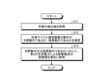
- 4 is a flow chart showing the operation of the control unit included in the power converter according to Embodiment 1;
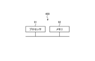
- FIG. 2 is a diagram showing an example of a hardware configuration that realizes a control unit included in the power converter according to Embodiment 1;
- a power conversion device, a motor drive device, and a refrigeration cycle application device will be described below in detail based on the drawings.
- FIG. 1 is a diagram showing a configuration example of a power conversion device 1 according to Embodiment 1.
- the power converter 1 is connected to a commercial power source 110 and a compressor 315 .
- Commercial power supply 110 is an example of an AC power supply.
- the power conversion device 1 converts first AC power of power supply voltage Vs supplied from the commercial power supply 110 into second AC power having desired amplitude and phase, and supplies the second AC power to the compressor 315 .
- the power conversion device 1 includes a voltage/current detection unit 501, a reactor 120, a rectification unit 130, a voltage detection unit 502, a smoothing unit 200, an inverter 310, current detection units 313a and 313b, and a temperature detection unit 504.
- a motor drive device 2 is configured by the power conversion device 1 and the motor 314 included in the compressor 315 .
- the power conversion device 1 is configured to be mountable on a refrigeration cycle application device, which will be described later.
- the voltage/current detection unit 501 detects the voltage value and current value of the first AC power of the power supply voltage Vs supplied from the commercial power supply 110 and outputs the detected voltage value and current value to the control unit 400 .
- Reactor 120 is connected between voltage/current detection unit 501 and rectification unit 130 .
- the rectifying section 130 has a bridge circuit composed of rectifying elements 131 to 134, rectifies the first AC power of the power supply voltage Vs supplied from the commercial power supply 110, and outputs it.
- the rectifier 130 performs full-wave rectification.
- the voltage detection section 502 detects the voltage value of the power rectified by the rectification section 130 and outputs the detected voltage value to the control section 400 .
- the smoothing section 200 is connected to the output terminal of the rectifying section 130 via the voltage detecting section 502 .
- Smoothing section 200 has capacitor 210 as a smoothing element, and smoothes the power rectified by rectifying section 130 .
- the capacitor 210 is, for example, an electrolytic capacitor, a film capacitor, or the like.
- Capacitor 210 has a capacity to smooth the power rectified by rectifying section 130 .
- the voltage generated in the capacitor 210 by smoothing does not have a full-wave rectified waveform of the commercial power supply 110, but has a waveform in which a voltage ripple corresponding to the frequency of the commercial power supply 110 is superimposed on the DC component, and does not greatly pulsate.
- the frequency of this voltage ripple is a component twice the frequency of the power supply voltage Vs when the commercial power supply 110 is single-phase, and the main component is a frequency component six times the frequency of the power supply voltage Vs when the commercial power supply 110 is three-phase.
- the amplitude of the voltage ripple is determined by the capacitance of capacitor 210 .
- the amplitude of the voltage ripple pulsates, for example, within a range such that the maximum value of the voltage ripple generated in capacitor 210 is less than twice the minimum value.
- the inverter 310 is connected to both ends of the smoothing section 200 , that is, the capacitor 210 .
- the inverter 310 has switching elements 311a-311f and freewheeling diodes 312a-312f.
- the inverter 310 turns on and off the switching elements 311a to 311f under the control of the control unit 400, converts the power output from the rectifying unit 130 and the smoothing unit 200 into second AC power having desired amplitude and phase, and compresses the power. output to machine 315.
- Each of the current detection units 313 a and 313 b detects the current value of one of the three phase currents output from the inverter 310 and outputs the detected current value to the control unit 400 .
- Control unit 400 acquires two-phase current values among the three-phase current values output from inverter 310, thereby calculating the remaining one-phase current value output from inverter 310. .
- the temperature detection unit 504 detects the temperature of the capacitor 210 or the ambient temperature of the capacitor 210 and outputs the detected temperature value to the control unit 400 .
- a temperature detector is provided on the control board or the circuit board. Therefore, instead of providing the temperature detection unit 504, the detected value of the temperature detector provided on the substrate may be used instead.
- a compressor 315 is a load having a motor 314 for driving the compressor.
- the motor 314 rotates according to the amplitude and phase of the second AC power supplied from the inverter 310 and performs compression operation.
- the load torque of the compressor 315 can often be regarded as a constant torque load.
- reactor 120 may be arranged after rectifying section 130 .
- the voltage/current detector 501, the voltage detector 502, and the current detectors 313a and 313b may be collectively referred to as detectors.
- the voltage value and current value detected by the voltage/current detection unit 501, the voltage value detected by the voltage detection unit 502, and the current values detected by the current detection units 313a and 313b may be referred to as detection values. .
- the control unit 400 acquires the voltage value and current value of the first AC power from the voltage/current detection unit 501 and acquires the voltage value of the power rectified by the rectification unit 130 from the voltage detection unit 502 . In addition, the control unit 400 acquires the current value of the second AC power having the desired amplitude and phase converted by the inverter 310 from the current detection units 313a and 313b, and the temperature of the capacitor 210 or the ambient temperature from the temperature detection unit 504 Get the temperature value of the temperature. Control unit 400 controls the operation of inverter 310, specifically, the on/off of switching elements 311a to 311f included in inverter 310, using the detection values detected by the respective detection units. Note that the control unit 400 does not have to use all the detection values acquired from each detection unit, and can perform control using some of the detection values.
- the control unit 400 controls the current flowing through the capacitor 210 of the smoothing unit 200 with the pulsating current generated by the second AC power. Specifically, the control unit 400 causes the inverter 310 to output the second AC power including the pulsation corresponding to the pulsation of the power flowing into the capacitor 210 of the smoothing unit 200 from the rectifying unit 130 to the compressor 315 which is the load.
- the operation of inverter 310 is controlled as follows.
- the pulsation according to the pulsation of the power flowing into the capacitor 210 of the smoothing section 200 is, for example, the pulsation that varies depending on the frequency of the pulsation of the power flowing into the capacitor 210 of the smoothing section 200 .
- the control unit 400 suppresses the current flowing through the capacitor 210 of the smoothing unit 200 .
- the load generated by the inverter 310 and the compressor 315 can be regarded as a constant load.
- the following description will be made on the assumption that a constant current load is connected to the smoothing section 200 in terms of the current output from the smoothing section 200 in the power converter 1 .
- the current flowing from the rectifying section 130 is current I1
- the current flowing to the inverter 310 is current I2
- the current flowing from the smoothing section 200 is current I3.
- the current I2 is the sum of the currents I1 and I3.
- the current I3 can be expressed as the difference between the currents I2 and I1, that is, the current resulting from the current I2 minus the current I1.
- the current I3 has a positive direction in the discharging direction of the smoothing section 200 and a negative direction in the charging direction of the smoothing section 200 . That is, current may flow into or out of the smoothing section 200 .
- FIG. 2 shows, as a comparative example, the currents I1 to I3 and the capacitor 210 of the smoothing unit 200 when the current output from the rectifying unit 130 is smoothed by the smoothing unit 200 and the current I2 flowing through the inverter 310 is kept constant.
- FIG. 4 is a diagram showing an example of voltage Vdc; The current I1, the current I2, the current I3, and the capacitor voltage Vdc of the capacitor 210 generated according to the current I3 are shown in order from the top.
- the vertical axis of currents I1, I2, and I3 indicates current values, and the vertical axis of capacitor voltage Vdc indicates voltage values. All horizontal axes indicate time t.
- the currents I2 and I3 are actually superimposed with the carrier component of the inverter 310, they are omitted here. The same shall apply to the following.
- the control unit 400 controls the current I2 flowing through the inverter 310 so that the current I3 flowing through the smoothing unit 200 is reduced, that is, controls the operation of the inverter 310. .
- FIG. 3 shows the respective currents I1 to I3 and the capacitor of the smoothing unit 200 when the control unit 400 of the power converter 1 according to Embodiment 1 controls the operation of the inverter 310 to reduce the current I3 flowing through the smoothing unit 200.
- 210 is a diagram showing an example of the capacitor voltage Vdc of 210.
- FIG. The current I1, the current I2, the current I3, and the capacitor voltage Vdc of the capacitor 210 generated according to the current I3 are shown in order from the top.
- the vertical axis of currents I1, I2, and I3 indicates current values, and the vertical axis of capacitor voltage Vdc indicates voltage values. All horizontal axes indicate time t.
- the control unit 400 of the power converter 1 controls the operation of the inverter 310 so that the current I2 shown in FIG. This control reduces the current flowing from the rectifying section 130 to the smoothing section 200 as compared with the example of FIG. 2, and as a result, the current I3 flowing to the smoothing section 200 is reduced. Specifically, control unit 400 controls the operation of inverter 310 so that current I2 containing a pulsating current whose main component is the frequency component of current I1 flows through inverter 310 .
- the frequency component of the current I1 is determined by the frequency of the alternating current supplied from the commercial power supply 110 and the configuration of the rectifying section 130. Therefore, the control unit 400 can make the frequency component of the pulsating current superimposed on the current I2 a component having a predetermined amplitude and phase.
- the frequency component of the pulsating current superimposed on the current I2 has a waveform similar to that of the current I1.
- the control unit 400 reduces the current I3 flowing through the smoothing unit 200 and reduces the pulsating voltage generated in the capacitor voltage Vdc. can do.
- Controlling the pulsation of the current flowing through inverter 310 by controlling the operation of inverter 310 by control unit 400 means controlling the pulsating current due to the second AC power output from inverter 310 to compressor 315 . are equivalent.
- the control unit 400 controls the inverter 310 so that the amount of pulsating current generated by the second AC power output from the inverter 310 is smaller than the pulsating current generated by the power output from the rectifying unit 130, that is, the pulsating width of the pulsating current. controls the behavior of
- the control unit 400 controls the pulsation of the current flowing into and out of the capacitor 210 when the pulsation corresponding to the pulsation of the power flowing into the capacitor 210 is not included in the second AC power output from the inverter 310 .
- the pulsating width of the pulsating current due to the second AC power output from the inverter 310 is controlled so as to be smaller than the pulsating current.
- the control unit 400 controls the pulsation of the voltage of the capacitor voltage Vdc, that is, the pulsation of the voltage generated in the capacitor 210 to cause the second AC power output from the inverter 310 to pulsate according to the pulsation of the power flowing into the capacitor 210.
- the pulsating width of the pulsating current due to the second AC power output from inverter 310 is controlled so as to be smaller than the pulsating voltage generated in capacitor 210 when no power is included.
- the control shown in FIG. 2 means that the second AC power output from inverter 310 does not include pulsation corresponding to the pulsation of the power flowing into capacitor 210 .
- the pulsation width is the difference between the maximum value and the minimum value of the pulsation current.
- the control described above is called "power supply ripple compensation control”. That is, the power supply ripple compensation control is control for suppressing the ripple current that may flow through the capacitor 210 of the smoothing section 200 due to the power supply ripple. According to the power supply ripple compensation control, most of the ripple current caused by the power supply ripple passes through the capacitor 210 and is supplied to the load. Therefore, by using the power supply ripple compensation control, the stress on the capacitor 210 can be reduced and the deterioration of the capacitor 210 can be suppressed.
- the alternating current supplied from the commercial power supply 110 is not particularly limited, and may be single-phase or three-phase.
- Control unit 400 may determine the frequency component of the pulsating current superimposed on current I2 according to the first AC power supplied from commercial power supply 110 . Specifically, when the first AC power supplied from commercial power supply 110 is single-phase, control unit 400 sets the pulsating waveform of current I2 flowing in inverter 310 to a frequency that is twice the frequency of the first AC power. component, or when the first AC power supplied from the commercial power supply 110 is three-phase, the pulsation waveform having a frequency component six times the frequency of the first AC power as the main component is controlled to a shape obtained by adding a DC component to the waveform. do.
- the pulsation waveform is, for example, the shape of the absolute value of a sine wave or the shape of a sine wave.
- the control unit 400 may add at least one frequency component of integral multiples of the sine wave frequency to the pulsating waveform as a predetermined amplitude.
- the pulsating waveform may be in the shape of a rectangular wave or in the shape of a triangular wave.
- the control unit 400 may set the amplitude and phase of the pulsation waveform to predetermined values.
- the control unit 400 may use the voltage applied to the capacitor 210 or the current flowing through the capacitor 210 to calculate the amount of pulsation of the pulsating current due to the second AC power output from the inverter 310 .
- the amount of pulsation of the pulsating current due to the second AC power output from the inverter 310 may be calculated using the voltage or current of the first AC power supplied from the inverter 310 .
- FIG. 4 is a flow chart showing the operation of the control unit 400 included in the power conversion device 1 according to the first embodiment.
- the control unit 400 acquires required detection values from each detection unit of the power converter 1 (step S11).
- the control unit 400 confirms whether the operation of the refrigeration cycle equipment is cooling operation or heating operation (step S12).
- the control unit 400 appropriately controls the pulsation width of the pulsating current generated by the second AC power depending on whether the operation is cooling operation or heating operation (step S13).
- the flowchart of FIG. 4 includes various operation modes.
- a first operation mode in Embodiment 1 in a state where predetermined power is received from commercial power supply 110, the pulsating current generated by the second AC power depends on whether the operation of the refrigeration cycle device is cooling operation or heating operation.
- operating the heat pump device of the refrigeration cycle equipment in the cooling cycle is called “cooling operation”
- operating the heat pump device of the refrigeration cycle equipment in the heating cycle is called "heating operation”.
- inverter 310 it is conceivable to control the operation of inverter 310 so that the pulsating width of the pulsating current due to the second AC power output from inverter 310 to motor 314 is larger during cooling operation than during heating operation. .
- the ambient temperature in the refrigerating cycle equipment is higher during the cooling operation, which accelerates deterioration of the life of the capacitor 210 . Therefore, control is performed so that the pulsating width of the pulsating current is larger during the cooling operation than during the heating operation.
- the power supply pulsation compensation control can be strongly effected during cooling operation when the outside air temperature is high. As a result, it is possible to effectively reduce the capacitor current under cooling conditions in which the temperature environment is severe, so that the self-heating of the capacitor 210 can be suppressed. This makes it possible to apply the capacitor 210 with a low heat-resistant temperature.
- the operation of the inverter 310 can be controlled so that the pulsating width of the pulsating current generated by the second AC power output from the inverter 310 to the motor 314 is larger during the heating operation than during the cooling operation.
- Conceivable When the refrigerating cycle application equipment is an air conditioner, there is a possibility that the air conditioner is operated for heating at an extremely low temperature in cold districts. Cryogenic temperatures are, for example, ⁇ 20° C. or below. Capacitors are generally known to lose capacitance with decreasing temperature. If the capacitance of capacitor 210 drops significantly, it becomes difficult to stably perform the air conditioning operation.
- control is performed so that the pulsating width of the pulsating current is greater during the heating operation than during the cooling operation.
- This control allows the capacitor 210 to be heated during the heating operation when the outside air temperature is low. As a result, even when the refrigerating cycle applied equipment is placed in an extremely low temperature environment, the refrigerating cycle applied equipment can be stably operated.
- the first operation mode described above it is possible to set the operation conditions according to the operation request of the refrigeration cycle applied equipment, so that it is possible to realize an appropriate protective operation for the capacitor 210 .
- the pulsation of the pulsating current due to the second AC power Width can be zero.
- the pulsation width of the pulsation current due to the second AC power is zero during both the cooling operation and the heating operation. sometimes not.
- Control by the first mode of operation may or may not be useful, depending on the product's function, where the product is used, or cost effectiveness. Therefore, it is desirable to decide whether or not to adopt control according to the first mode of operation, taking into consideration the function of the product, the place of use of the product, or cost effectiveness.
- Embodiment 1 when the operation of the refrigerating cycle-applied equipment is the heating operation, the pulsation width of the pulsating current generated by the second AC power is increased or This is an operation mode in which the phase of the current is changed to heat the capacitor 210 .
- the refrigerating cycle application equipment is an air conditioner
- the above-described power supply pulsation compensation control is performed in the same way as the cooling operation performed when the outside temperature is high both when the outside temperature is low and when the outside temperature is high. , there is a problem that the heating of the capacitor 210 is not sufficiently accelerated during the heating operation performed when the outside air temperature is low.
- the pulsating width of the pulsating current generated by the second AC power is increased or the phase of the pulsating current is changed to positively add the capacitor 210 . Warm up.
- This control promotes heat generation in capacitor 210 .
- the refrigerating cycle applied equipment can be stably operated.
- the phase of the pulsating current when the capacitor 210 is heated by changing the phase of the pulsating current can be opposite to the phase of the pulsating current when suppressing the pulsation of the current flowing through the capacitor 210.
- the opposite phase means to reverse the phase of the pulsating current by 180°.
- Embodiment 1 a third operation mode in Embodiment 1 will be described.
- the pulsation width of the pulsating current generated by the second AC power is reduced so that heat generation of capacitor 210 is alleviated. or the ambient temperature is equal to or lower than a second threshold that is smaller than the first threshold, the pulsating width of the pulsating current generated by the second AC power is increased so as to promote heat generation in the capacitor 210.
- the phase of the pulsating current may be changed instead of decreasing or increasing the pulsating width of the pulsating current generated by the second AC power.
- the third operation mode it is possible to control the temperature of the capacitor 210 according to the temperature conditions. As a result, the stress on the capacitor 210 can be reduced and the deterioration of the capacitor 210 can be suppressed, so that the refrigeration cycle equipment can be stably operated.
- control by the second and third modes of operation may or may not be useful depending on the function of the product, where the product is used, or cost effectiveness. The case is considered. Therefore, it is desirable to decide whether or not to adopt the control according to the second and third modes of operation, taking into consideration the function of the product, the place of use of the product, or cost effectiveness.
- FIG. 5 is a diagram showing an example of a hardware configuration that implements the control unit 400 included in the power converter 1 according to Embodiment 1. As shown in FIG. The control unit 400 is implemented by the processor 91 and memory 92 .
- the processor 91 is a CPU (Central Processing Unit, central processing unit, processing unit, arithmetic unit, microprocessor, microcomputer, processor, DSP (Digital Signal Processor)), or a system LSI (Large Scale Integration).
- the memory 92 includes RAM (Random Access Memory), ROM (Read Only Memory), flash memory, EPROM (Erasable Programmable Read Only Memory), EEPROM (registered trademark) (Electrically Erasable Programmable Read Non-volatile or volatile such as Only Memory)
- RAM Random Access Memory
- ROM Read Only Memory
- flash memory flash memory
- EPROM Erasable Programmable Read Only Memory
- EEPROM registered trademark
- a semiconductor memory can be exemplified.
- the memory 92 is not limited to these, and may be a magnetic disk, an optical disk, a compact disk, a mini disk, or a DVD (Digital Versatile Disc).
- the second AC power including pulsation corresponding to the pulsation of the power flowing into the capacitor 210 from the rectifier 130 is output from the inverter 310 to the motor 314.
- the operation of the inverter 310 is controlled so that the current flowing through the capacitor 210 is suppressed.
- This control reduces the stress on the capacitor 210 and suppresses deterioration of the capacitor 210 .
- the capacity of the capacitor 210 can be reduced, or a capacitor 210 with a small resistance to deterioration due to ripples can be used, so that the power conversion device 1 can be suppressed from increasing in size.
- the pulsation of the pulsating current due to the second AC power depends on whether the operation of the refrigeration cycle applied equipment is the cooling operation or the heating operation. It works so that the width can be different values. According to the refrigerating cycle applied equipment equipped with the power conversion device 1 that operates in this manner, it is possible to perform cooling operation, heating operation, and operation suitable for temperature environmental conditions. As a result, the refrigeration cycle applied equipment can be stably operated.
- FIG. 6 is a diagram showing a configuration example of a refrigeration cycle application device 900 according to Embodiment 2.
- a refrigerating cycle-applied equipment 900 according to the second embodiment includes the power converter 1 described in the first embodiment.
- the refrigerating cycle applied equipment 900 according to Embodiment 2 can be applied to products equipped with a refrigerating cycle, such as air conditioners, refrigerators, freezers, and heat pump water heaters.
- constituent elements having functions similar to those of the first embodiment are denoted by the same reference numerals as those of the first embodiment.
- Refrigerating cycle applied equipment 900 includes compressor 315 incorporating motor 314 according to Embodiment 1, four-way valve 902, indoor heat exchanger 906, expansion valve 908, and outdoor heat exchanger 910 with refrigerant pipe 912. attached through
- a compression mechanism 904 that compresses the refrigerant and a motor 314 that operates the compression mechanism 904 are provided inside the compressor 315 .
- the refrigeration cycle applied equipment 900 can perform heating operation or cooling operation by switching operation of the four-way valve 902 .
- the compression mechanism 904 is driven by a variable speed controlled motor 314 .
- the refrigerant is pressurized by the compression mechanism 904 and sent out through the four-way valve 902, the indoor heat exchanger 906, the expansion valve 908, the outdoor heat exchanger 910, and the four-way valve 902. Return to compression mechanism 904 .
- the refrigerant is pressurized by the compression mechanism 904 and sent through the four-way valve 902, the outdoor heat exchanger 910, the expansion valve 908, the indoor heat exchanger 906, and the four-way valve 902. Return to compression mechanism 904 .
- the indoor heat exchanger 906 acts as a condenser to release heat, and the outdoor heat exchanger 910 acts as an evaporator to absorb heat.
- the outdoor heat exchanger 910 acts as a condenser to release heat, and the indoor heat exchanger 906 acts as an evaporator to absorb heat.
- the expansion valve 908 reduces the pressure of the refrigerant to expand it.
- the configuration shown in the above embodiment shows an example, and can be combined with another known technique, and part of the configuration can be omitted or changed without departing from the scope of the invention. is also possible. Further, the operation shown in the above embodiment is also an example, and it is possible to combine the above-described first to third operation modes, and another known operation mode is possible without departing from the scope of the invention. It is also possible to combine with the technology of
Landscapes
- Engineering & Computer Science (AREA)
- Power Engineering (AREA)
- Chemical & Material Sciences (AREA)
- Combustion & Propulsion (AREA)
- Mechanical Engineering (AREA)
- General Engineering & Computer Science (AREA)
- Inverter Devices (AREA)
Priority Applications (4)
| Application Number | Priority Date | Filing Date | Title |
|---|---|---|---|
| JP2023563428A JP7630643B2 (ja) | 2021-11-25 | 2021-11-25 | 電力変換装置、モータ駆動装置及び冷凍サイクル適用機器 |
| PCT/JP2021/043271 WO2023095264A1 (ja) | 2021-11-25 | 2021-11-25 | 電力変換装置、モータ駆動装置及び冷凍サイクル適用機器 |
| US18/705,853 US20250007388A1 (en) | 2021-11-25 | 2021-11-25 | Power converter, motor driver, and refrigeration cycle applied equipment |
| CN202180104287.0A CN118265877A (zh) | 2021-11-25 | 2021-11-25 | 电力转换装置、马达驱动装置以及制冷循环应用设备 |
Applications Claiming Priority (1)
| Application Number | Priority Date | Filing Date | Title |
|---|---|---|---|
| PCT/JP2021/043271 WO2023095264A1 (ja) | 2021-11-25 | 2021-11-25 | 電力変換装置、モータ駆動装置及び冷凍サイクル適用機器 |
Publications (1)
| Publication Number | Publication Date |
|---|---|
| WO2023095264A1 true WO2023095264A1 (ja) | 2023-06-01 |
Family
ID=86539126
Family Applications (1)
| Application Number | Title | Priority Date | Filing Date |
|---|---|---|---|
| PCT/JP2021/043271 Ceased WO2023095264A1 (ja) | 2021-11-25 | 2021-11-25 | 電力変換装置、モータ駆動装置及び冷凍サイクル適用機器 |
Country Status (4)
| Country | Link |
|---|---|
| US (1) | US20250007388A1 (https=) |
| JP (1) | JP7630643B2 (https=) |
| CN (1) | CN118265877A (https=) |
| WO (1) | WO2023095264A1 (https=) |
Families Citing this family (1)
| Publication number | Priority date | Publication date | Assignee | Title |
|---|---|---|---|---|
| JP7345673B2 (ja) | 2020-10-26 | 2023-09-15 | 三菱電機株式会社 | 電力変換装置、モータ駆動装置および冷凍サイクル適用機器 |
Citations (3)
| Publication number | Priority date | Publication date | Assignee | Title |
|---|---|---|---|---|
| WO2007108185A1 (ja) * | 2006-03-15 | 2007-09-27 | Mitsubishi Electric Corporation | 電動機駆動装置及び圧縮機駆動装置 |
| US20150354880A1 (en) * | 2014-06-09 | 2015-12-10 | Lg Electronics Inc. | Motor driving device and air conditioner including the same |
| WO2020213511A1 (ja) * | 2019-04-19 | 2020-10-22 | ダイキン工業株式会社 | 空気調和装置 |
Family Cites Families (7)
| Publication number | Priority date | Publication date | Assignee | Title |
|---|---|---|---|---|
| US6313602B1 (en) * | 1999-04-30 | 2001-11-06 | Texas Instruments Incorporated | Modified space vector pulse width modulation technique to reduce DC bus ripple effect in voltage source inverters |
| JP4313253B2 (ja) * | 2004-06-23 | 2009-08-12 | オリジン電気株式会社 | パラレルシーム接合装置 |
| CN105027424B (zh) * | 2013-03-29 | 2017-09-12 | 爱信艾达株式会社 | 旋转电机驱动装置 |
| WO2015140867A1 (ja) * | 2014-03-15 | 2015-09-24 | 三菱電機株式会社 | モータ駆動制御装置、圧縮機、送風機、及び空気調和機 |
| EP4231517B1 (en) * | 2017-09-29 | 2025-02-12 | Daikin Industries, Ltd. | Power conversion device |
| WO2022172419A1 (ja) | 2021-02-12 | 2022-08-18 | 三菱電機株式会社 | 電力変換装置、モータ駆動装置および空気調和機 |
| JP7595807B2 (ja) * | 2022-02-24 | 2024-12-06 | 三菱電機株式会社 | モータ駆動装置及び冷凍サイクル装置 |
-
2021
- 2021-11-25 US US18/705,853 patent/US20250007388A1/en active Pending
- 2021-11-25 WO PCT/JP2021/043271 patent/WO2023095264A1/ja not_active Ceased
- 2021-11-25 CN CN202180104287.0A patent/CN118265877A/zh active Pending
- 2021-11-25 JP JP2023563428A patent/JP7630643B2/ja active Active
Patent Citations (3)
| Publication number | Priority date | Publication date | Assignee | Title |
|---|---|---|---|---|
| WO2007108185A1 (ja) * | 2006-03-15 | 2007-09-27 | Mitsubishi Electric Corporation | 電動機駆動装置及び圧縮機駆動装置 |
| US20150354880A1 (en) * | 2014-06-09 | 2015-12-10 | Lg Electronics Inc. | Motor driving device and air conditioner including the same |
| WO2020213511A1 (ja) * | 2019-04-19 | 2020-10-22 | ダイキン工業株式会社 | 空気調和装置 |
Also Published As
| Publication number | Publication date |
|---|---|
| JPWO2023095264A1 (https=) | 2023-06-01 |
| CN118265877A (zh) | 2024-06-28 |
| US20250007388A1 (en) | 2025-01-02 |
| JP7630643B2 (ja) | 2025-02-17 |
Similar Documents
| Publication | Publication Date | Title |
|---|---|---|
| US8169180B2 (en) | Motor controller of air conditioner | |
| US9625190B2 (en) | Motor driving device and air conditioner including the same | |
| JP7345674B2 (ja) | 電力変換装置、モータ駆動装置および冷凍サイクル適用機器 | |
| US9543884B2 (en) | Motor control device of air conditioner using distributed power supply | |
| JP7345673B2 (ja) | 電力変換装置、モータ駆動装置および冷凍サイクル適用機器 | |
| JP7387038B2 (ja) | 電力変換装置、モータ駆動装置および空気調和機 | |
| WO2022091186A1 (ja) | 電力変換装置、モータ駆動装置および冷凍サイクル適用機器 | |
| KR20140112297A (ko) | 전력변환장치, 및 이를 구비하는 공기조화기 | |
| JP7378651B2 (ja) | 電力変換装置、モータ駆動装置及び冷凍サイクル適用機器 | |
| WO2022172418A1 (ja) | 電力変換装置、モータ駆動装置および冷凍サイクル適用機器 | |
| WO2023095264A1 (ja) | 電力変換装置、モータ駆動装置及び冷凍サイクル適用機器 | |
| WO2019088118A1 (ja) | 電力変換装置及び空気調和装置 | |
| WO2023105570A1 (ja) | 電力変換装置、モータ駆動装置及び冷凍サイクル適用機器 | |
| KR20140112298A (ko) | 전력변환장치, 및 이를 구비하는 공기조화기 | |
| WO2022149208A1 (ja) | 電力変換装置、モータ駆動装置及び冷凍サイクル適用機器 | |
| WO2023238229A1 (ja) | 電力変換装置、モータ駆動装置及び冷凍サイクル適用機器 | |
| WO2024176332A1 (ja) | 電力変換装置、モータ駆動装置及び冷凍サイクル適用機器 | |
| JP2013194969A (ja) | 空気調和装置 | |
| JP5013922B2 (ja) | 三相整流装置及び冷凍サイクル装置 | |
| KR102302240B1 (ko) | 전력 변환 장치 및 제어 방법, 이를 이용한 공기조화기 | |
| WO2025120780A1 (ja) | 電力変換装置、モータ駆動装置および冷凍サイクル適用機器 | |
| WO2023105676A1 (ja) | 電力変換装置、モータ駆動装置及び冷凍サイクル適用機器 | |
| KR20090081910A (ko) | 공기조화기 |
Legal Events
| Date | Code | Title | Description |
|---|---|---|---|
| 121 | Ep: the epo has been informed by wipo that ep was designated in this application |
Ref document number: 21965636 Country of ref document: EP Kind code of ref document: A1 |
|
| WWE | Wipo information: entry into national phase |
Ref document number: 2023563428 Country of ref document: JP |
|
| WWE | Wipo information: entry into national phase |
Ref document number: 18705853 Country of ref document: US |
|
| WWE | Wipo information: entry into national phase |
Ref document number: 202180104287.0 Country of ref document: CN |
|
| WWE | Wipo information: entry into national phase |
Ref document number: 202427038953 Country of ref document: IN |
|
| NENP | Non-entry into the national phase |
Ref country code: DE |
|
| 122 | Ep: pct application non-entry in european phase |
Ref document number: 21965636 Country of ref document: EP Kind code of ref document: A1 |