WO2023095264A1 - Power conversion device, motor drive device, and refrigeration cycle application equipment - Google Patents
Power conversion device, motor drive device, and refrigeration cycle application equipment Download PDFInfo
- Publication number
- WO2023095264A1 WO2023095264A1 PCT/JP2021/043271 JP2021043271W WO2023095264A1 WO 2023095264 A1 WO2023095264 A1 WO 2023095264A1 JP 2021043271 W JP2021043271 W JP 2021043271W WO 2023095264 A1 WO2023095264 A1 WO 2023095264A1
- Authority
- WO
- WIPO (PCT)
- Prior art keywords
- power
- capacitor
- inverter
- current
- pulsating
- Prior art date
Links
- 238000006243 chemical reaction Methods 0.000 title claims abstract description 29
- 238000005057 refrigeration Methods 0.000 title claims abstract description 23
- 239000003990 capacitor Substances 0.000 claims abstract description 108
- 230000010349 pulsation Effects 0.000 claims abstract description 48
- 238000010438 heat treatment Methods 0.000 claims abstract description 31
- 238000001816 cooling Methods 0.000 claims abstract description 27
- 230000020169 heat generation Effects 0.000 claims description 5
- 238000009499 grossing Methods 0.000 description 41
- 238000001514 detection method Methods 0.000 description 29
- 230000006866 deterioration Effects 0.000 description 10
- 230000006835 compression Effects 0.000 description 9
- 238000007906 compression Methods 0.000 description 9
- 238000010586 diagram Methods 0.000 description 9
- 239000003507 refrigerant Substances 0.000 description 6
- 230000006870 function Effects 0.000 description 5
- 238000005516 engineering process Methods 0.000 description 3
- 230000035882 stress Effects 0.000 description 3
- 230000000052 comparative effect Effects 0.000 description 2
- 230000003247 decreasing effect Effects 0.000 description 2
- 238000000034 method Methods 0.000 description 2
- 230000032683 aging Effects 0.000 description 1
- 238000004378 air conditioning Methods 0.000 description 1
- 238000013459 approach Methods 0.000 description 1
- 230000006399 behavior Effects 0.000 description 1
- 239000000470 constituent Substances 0.000 description 1
- 238000007599 discharging Methods 0.000 description 1
- 230000000694 effects Effects 0.000 description 1
- 230000007613 environmental effect Effects 0.000 description 1
- 230000010354 integration Effects 0.000 description 1
- 230000003287 optical effect Effects 0.000 description 1
- 230000001681 protective effect Effects 0.000 description 1
- 239000004065 semiconductor Substances 0.000 description 1
- 239000000758 substrate Substances 0.000 description 1
- XLYOFNOQVPJJNP-UHFFFAOYSA-N water Substances O XLYOFNOQVPJJNP-UHFFFAOYSA-N 0.000 description 1
Images


Classifications
-
- F—MECHANICAL ENGINEERING; LIGHTING; HEATING; WEAPONS; BLASTING
- F24—HEATING; RANGES; VENTILATING
- F24F—AIR-CONDITIONING; AIR-HUMIDIFICATION; VENTILATION; USE OF AIR CURRENTS FOR SCREENING
- F24F11/00—Control or safety arrangements
- F24F11/88—Electrical aspects, e.g. circuits
-
- H—ELECTRICITY
- H02—GENERATION; CONVERSION OR DISTRIBUTION OF ELECTRIC POWER
- H02M—APPARATUS FOR CONVERSION BETWEEN AC AND AC, BETWEEN AC AND DC, OR BETWEEN DC AND DC, AND FOR USE WITH MAINS OR SIMILAR POWER SUPPLY SYSTEMS; CONVERSION OF DC OR AC INPUT POWER INTO SURGE OUTPUT POWER; CONTROL OR REGULATION THEREOF
- H02M7/00—Conversion of ac power input into dc power output; Conversion of dc power input into ac power output
- H02M7/42—Conversion of dc power input into ac power output without possibility of reversal
- H02M7/44—Conversion of dc power input into ac power output without possibility of reversal by static converters
- H02M7/48—Conversion of dc power input into ac power output without possibility of reversal by static converters using discharge tubes with control electrode or semiconductor devices with control electrode
Definitions
- the present disclosure relates to a power conversion device, a motor drive device, and a refrigeration cycle application device that convert AC power into desired power.
- a power conversion device that converts AC power supplied from an AC power supply into desired AC power and supplies it to a load such as an air conditioner.
- a power converter which is a control device for an air conditioner, rectifies AC power supplied from an AC power supply with a diode stack, which is a rectifier, and smoothes the power with a smoothing capacitor.
- a technology is disclosed in which the AC power is converted into a desired AC power by an inverter composed of switching elements and output to a compressor motor, which is a load.
- the present disclosure has been made in view of the above, and an object thereof is to obtain a power conversion device capable of suppressing an increase in device size while suppressing deterioration of a smoothing capacitor.
- a power conversion device is a power conversion device mounted on a refrigeration cycle application device, and is connected to a rectification section and an output end of the rectification section.
- an inverter connected to both ends of the capacitor; and a controller.
- the rectifier rectifies first AC power supplied from an AC power supply.
- the inverter converts the power output from the rectifier and the capacitor into second AC power, and outputs the second AC power to a load having a motor.
- the control unit controls the operation of the inverter so that the second AC power including pulsation corresponding to the pulsation of the power flowing into the capacitor from the rectifying unit is output from the inverter to the load, thereby suppressing the current flowing through the capacitor.
- the pulsation width of the pulsating current generated by the second AC power varies depending on whether the operation of the refrigeration cycle device is cooling operation or heating operation. It behaves like a different value.
- the power converter according to the present disclosure has the effect of suppressing the deterioration of the smoothing capacitor and suppressing the enlargement of the device.
- FIG. 1 is a diagram showing a configuration example of a power converter according to Embodiment 1;
- FIG. 4 is a diagram showing an example of each current and the capacitor voltage of the smoothing unit when the control unit of the power converter according to the first embodiment controls the operation of the inverter to reduce the current flowing through the smoothing unit;
- 4 is a flow chart showing the operation of the control unit included in the power converter according to Embodiment 1;
- FIG. 2 is a diagram showing an example of a hardware configuration that realizes a control unit included in the power converter according to Embodiment 1;
- a power conversion device, a motor drive device, and a refrigeration cycle application device will be described below in detail based on the drawings.
- FIG. 1 is a diagram showing a configuration example of a power conversion device 1 according to Embodiment 1.
- the power converter 1 is connected to a commercial power source 110 and a compressor 315 .
- Commercial power supply 110 is an example of an AC power supply.
- the power conversion device 1 converts first AC power of power supply voltage Vs supplied from the commercial power supply 110 into second AC power having desired amplitude and phase, and supplies the second AC power to the compressor 315 .
- the power conversion device 1 includes a voltage/current detection unit 501, a reactor 120, a rectification unit 130, a voltage detection unit 502, a smoothing unit 200, an inverter 310, current detection units 313a and 313b, and a temperature detection unit 504.
- a motor drive device 2 is configured by the power conversion device 1 and the motor 314 included in the compressor 315 .
- the power conversion device 1 is configured to be mountable on a refrigeration cycle application device, which will be described later.
- the voltage/current detection unit 501 detects the voltage value and current value of the first AC power of the power supply voltage Vs supplied from the commercial power supply 110 and outputs the detected voltage value and current value to the control unit 400 .
- Reactor 120 is connected between voltage/current detection unit 501 and rectification unit 130 .
- the rectifying section 130 has a bridge circuit composed of rectifying elements 131 to 134, rectifies the first AC power of the power supply voltage Vs supplied from the commercial power supply 110, and outputs it.
- the rectifier 130 performs full-wave rectification.
- the voltage detection section 502 detects the voltage value of the power rectified by the rectification section 130 and outputs the detected voltage value to the control section 400 .
- the smoothing section 200 is connected to the output terminal of the rectifying section 130 via the voltage detecting section 502 .
- Smoothing section 200 has capacitor 210 as a smoothing element, and smoothes the power rectified by rectifying section 130 .
- the capacitor 210 is, for example, an electrolytic capacitor, a film capacitor, or the like.
- Capacitor 210 has a capacity to smooth the power rectified by rectifying section 130 .
- the voltage generated in the capacitor 210 by smoothing does not have a full-wave rectified waveform of the commercial power supply 110, but has a waveform in which a voltage ripple corresponding to the frequency of the commercial power supply 110 is superimposed on the DC component, and does not greatly pulsate.
- the frequency of this voltage ripple is a component twice the frequency of the power supply voltage Vs when the commercial power supply 110 is single-phase, and the main component is a frequency component six times the frequency of the power supply voltage Vs when the commercial power supply 110 is three-phase.
- the amplitude of the voltage ripple is determined by the capacitance of capacitor 210 .
- the amplitude of the voltage ripple pulsates, for example, within a range such that the maximum value of the voltage ripple generated in capacitor 210 is less than twice the minimum value.
- the inverter 310 is connected to both ends of the smoothing section 200 , that is, the capacitor 210 .
- the inverter 310 has switching elements 311a-311f and freewheeling diodes 312a-312f.
- the inverter 310 turns on and off the switching elements 311a to 311f under the control of the control unit 400, converts the power output from the rectifying unit 130 and the smoothing unit 200 into second AC power having desired amplitude and phase, and compresses the power. output to machine 315.
- Each of the current detection units 313 a and 313 b detects the current value of one of the three phase currents output from the inverter 310 and outputs the detected current value to the control unit 400 .
- Control unit 400 acquires two-phase current values among the three-phase current values output from inverter 310, thereby calculating the remaining one-phase current value output from inverter 310. .
- the temperature detection unit 504 detects the temperature of the capacitor 210 or the ambient temperature of the capacitor 210 and outputs the detected temperature value to the control unit 400 .
- a temperature detector is provided on the control board or the circuit board. Therefore, instead of providing the temperature detection unit 504, the detected value of the temperature detector provided on the substrate may be used instead.
- a compressor 315 is a load having a motor 314 for driving the compressor.
- the motor 314 rotates according to the amplitude and phase of the second AC power supplied from the inverter 310 and performs compression operation.
- the load torque of the compressor 315 can often be regarded as a constant torque load.
- reactor 120 may be arranged after rectifying section 130 .
- the voltage/current detector 501, the voltage detector 502, and the current detectors 313a and 313b may be collectively referred to as detectors.
- the voltage value and current value detected by the voltage/current detection unit 501, the voltage value detected by the voltage detection unit 502, and the current values detected by the current detection units 313a and 313b may be referred to as detection values. .
- the control unit 400 acquires the voltage value and current value of the first AC power from the voltage/current detection unit 501 and acquires the voltage value of the power rectified by the rectification unit 130 from the voltage detection unit 502 . In addition, the control unit 400 acquires the current value of the second AC power having the desired amplitude and phase converted by the inverter 310 from the current detection units 313a and 313b, and the temperature of the capacitor 210 or the ambient temperature from the temperature detection unit 504 Get the temperature value of the temperature. Control unit 400 controls the operation of inverter 310, specifically, the on/off of switching elements 311a to 311f included in inverter 310, using the detection values detected by the respective detection units. Note that the control unit 400 does not have to use all the detection values acquired from each detection unit, and can perform control using some of the detection values.
- the control unit 400 controls the current flowing through the capacitor 210 of the smoothing unit 200 with the pulsating current generated by the second AC power. Specifically, the control unit 400 causes the inverter 310 to output the second AC power including the pulsation corresponding to the pulsation of the power flowing into the capacitor 210 of the smoothing unit 200 from the rectifying unit 130 to the compressor 315 which is the load.
- the operation of inverter 310 is controlled as follows.
- the pulsation according to the pulsation of the power flowing into the capacitor 210 of the smoothing section 200 is, for example, the pulsation that varies depending on the frequency of the pulsation of the power flowing into the capacitor 210 of the smoothing section 200 .
- the control unit 400 suppresses the current flowing through the capacitor 210 of the smoothing unit 200 .
- the load generated by the inverter 310 and the compressor 315 can be regarded as a constant load.
- the following description will be made on the assumption that a constant current load is connected to the smoothing section 200 in terms of the current output from the smoothing section 200 in the power converter 1 .
- the current flowing from the rectifying section 130 is current I1
- the current flowing to the inverter 310 is current I2
- the current flowing from the smoothing section 200 is current I3.
- the current I2 is the sum of the currents I1 and I3.
- the current I3 can be expressed as the difference between the currents I2 and I1, that is, the current resulting from the current I2 minus the current I1.
- the current I3 has a positive direction in the discharging direction of the smoothing section 200 and a negative direction in the charging direction of the smoothing section 200 . That is, current may flow into or out of the smoothing section 200 .
- FIG. 2 shows, as a comparative example, the currents I1 to I3 and the capacitor 210 of the smoothing unit 200 when the current output from the rectifying unit 130 is smoothed by the smoothing unit 200 and the current I2 flowing through the inverter 310 is kept constant.
- FIG. 4 is a diagram showing an example of voltage Vdc; The current I1, the current I2, the current I3, and the capacitor voltage Vdc of the capacitor 210 generated according to the current I3 are shown in order from the top.
- the vertical axis of currents I1, I2, and I3 indicates current values, and the vertical axis of capacitor voltage Vdc indicates voltage values. All horizontal axes indicate time t.
- the currents I2 and I3 are actually superimposed with the carrier component of the inverter 310, they are omitted here. The same shall apply to the following.
- the control unit 400 controls the current I2 flowing through the inverter 310 so that the current I3 flowing through the smoothing unit 200 is reduced, that is, controls the operation of the inverter 310. .
- FIG. 3 shows the respective currents I1 to I3 and the capacitor of the smoothing unit 200 when the control unit 400 of the power converter 1 according to Embodiment 1 controls the operation of the inverter 310 to reduce the current I3 flowing through the smoothing unit 200.
- 210 is a diagram showing an example of the capacitor voltage Vdc of 210.
- FIG. The current I1, the current I2, the current I3, and the capacitor voltage Vdc of the capacitor 210 generated according to the current I3 are shown in order from the top.
- the vertical axis of currents I1, I2, and I3 indicates current values, and the vertical axis of capacitor voltage Vdc indicates voltage values. All horizontal axes indicate time t.
- the control unit 400 of the power converter 1 controls the operation of the inverter 310 so that the current I2 shown in FIG. This control reduces the current flowing from the rectifying section 130 to the smoothing section 200 as compared with the example of FIG. 2, and as a result, the current I3 flowing to the smoothing section 200 is reduced. Specifically, control unit 400 controls the operation of inverter 310 so that current I2 containing a pulsating current whose main component is the frequency component of current I1 flows through inverter 310 .
- the frequency component of the current I1 is determined by the frequency of the alternating current supplied from the commercial power supply 110 and the configuration of the rectifying section 130. Therefore, the control unit 400 can make the frequency component of the pulsating current superimposed on the current I2 a component having a predetermined amplitude and phase.
- the frequency component of the pulsating current superimposed on the current I2 has a waveform similar to that of the current I1.
- the control unit 400 reduces the current I3 flowing through the smoothing unit 200 and reduces the pulsating voltage generated in the capacitor voltage Vdc. can do.
- Controlling the pulsation of the current flowing through inverter 310 by controlling the operation of inverter 310 by control unit 400 means controlling the pulsating current due to the second AC power output from inverter 310 to compressor 315 . are equivalent.
- the control unit 400 controls the inverter 310 so that the amount of pulsating current generated by the second AC power output from the inverter 310 is smaller than the pulsating current generated by the power output from the rectifying unit 130, that is, the pulsating width of the pulsating current. controls the behavior of
- the control unit 400 controls the pulsation of the current flowing into and out of the capacitor 210 when the pulsation corresponding to the pulsation of the power flowing into the capacitor 210 is not included in the second AC power output from the inverter 310 .
- the pulsating width of the pulsating current due to the second AC power output from the inverter 310 is controlled so as to be smaller than the pulsating current.
- the control unit 400 controls the pulsation of the voltage of the capacitor voltage Vdc, that is, the pulsation of the voltage generated in the capacitor 210 to cause the second AC power output from the inverter 310 to pulsate according to the pulsation of the power flowing into the capacitor 210.
- the pulsating width of the pulsating current due to the second AC power output from inverter 310 is controlled so as to be smaller than the pulsating voltage generated in capacitor 210 when no power is included.
- the control shown in FIG. 2 means that the second AC power output from inverter 310 does not include pulsation corresponding to the pulsation of the power flowing into capacitor 210 .
- the pulsation width is the difference between the maximum value and the minimum value of the pulsation current.
- the control described above is called "power supply ripple compensation control”. That is, the power supply ripple compensation control is control for suppressing the ripple current that may flow through the capacitor 210 of the smoothing section 200 due to the power supply ripple. According to the power supply ripple compensation control, most of the ripple current caused by the power supply ripple passes through the capacitor 210 and is supplied to the load. Therefore, by using the power supply ripple compensation control, the stress on the capacitor 210 can be reduced and the deterioration of the capacitor 210 can be suppressed.
- the alternating current supplied from the commercial power supply 110 is not particularly limited, and may be single-phase or three-phase.
- Control unit 400 may determine the frequency component of the pulsating current superimposed on current I2 according to the first AC power supplied from commercial power supply 110 . Specifically, when the first AC power supplied from commercial power supply 110 is single-phase, control unit 400 sets the pulsating waveform of current I2 flowing in inverter 310 to a frequency that is twice the frequency of the first AC power. component, or when the first AC power supplied from the commercial power supply 110 is three-phase, the pulsation waveform having a frequency component six times the frequency of the first AC power as the main component is controlled to a shape obtained by adding a DC component to the waveform. do.
- the pulsation waveform is, for example, the shape of the absolute value of a sine wave or the shape of a sine wave.
- the control unit 400 may add at least one frequency component of integral multiples of the sine wave frequency to the pulsating waveform as a predetermined amplitude.
- the pulsating waveform may be in the shape of a rectangular wave or in the shape of a triangular wave.
- the control unit 400 may set the amplitude and phase of the pulsation waveform to predetermined values.
- the control unit 400 may use the voltage applied to the capacitor 210 or the current flowing through the capacitor 210 to calculate the amount of pulsation of the pulsating current due to the second AC power output from the inverter 310 .
- the amount of pulsation of the pulsating current due to the second AC power output from the inverter 310 may be calculated using the voltage or current of the first AC power supplied from the inverter 310 .
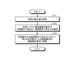
- FIG. 4 is a flow chart showing the operation of the control unit 400 included in the power conversion device 1 according to the first embodiment.
- the control unit 400 acquires required detection values from each detection unit of the power converter 1 (step S11).
- the control unit 400 confirms whether the operation of the refrigeration cycle equipment is cooling operation or heating operation (step S12).
- the control unit 400 appropriately controls the pulsation width of the pulsating current generated by the second AC power depending on whether the operation is cooling operation or heating operation (step S13).
- the flowchart of FIG. 4 includes various operation modes.
- a first operation mode in Embodiment 1 in a state where predetermined power is received from commercial power supply 110, the pulsating current generated by the second AC power depends on whether the operation of the refrigeration cycle device is cooling operation or heating operation.
- operating the heat pump device of the refrigeration cycle equipment in the cooling cycle is called “cooling operation”
- operating the heat pump device of the refrigeration cycle equipment in the heating cycle is called "heating operation”.
- inverter 310 it is conceivable to control the operation of inverter 310 so that the pulsating width of the pulsating current due to the second AC power output from inverter 310 to motor 314 is larger during cooling operation than during heating operation. .
- the ambient temperature in the refrigerating cycle equipment is higher during the cooling operation, which accelerates deterioration of the life of the capacitor 210 . Therefore, control is performed so that the pulsating width of the pulsating current is larger during the cooling operation than during the heating operation.
- the power supply pulsation compensation control can be strongly effected during cooling operation when the outside air temperature is high. As a result, it is possible to effectively reduce the capacitor current under cooling conditions in which the temperature environment is severe, so that the self-heating of the capacitor 210 can be suppressed. This makes it possible to apply the capacitor 210 with a low heat-resistant temperature.
- the operation of the inverter 310 can be controlled so that the pulsating width of the pulsating current generated by the second AC power output from the inverter 310 to the motor 314 is larger during the heating operation than during the cooling operation.
- Conceivable When the refrigerating cycle application equipment is an air conditioner, there is a possibility that the air conditioner is operated for heating at an extremely low temperature in cold districts. Cryogenic temperatures are, for example, ⁇ 20° C. or below. Capacitors are generally known to lose capacitance with decreasing temperature. If the capacitance of capacitor 210 drops significantly, it becomes difficult to stably perform the air conditioning operation.
- control is performed so that the pulsating width of the pulsating current is greater during the heating operation than during the cooling operation.
- This control allows the capacitor 210 to be heated during the heating operation when the outside air temperature is low. As a result, even when the refrigerating cycle applied equipment is placed in an extremely low temperature environment, the refrigerating cycle applied equipment can be stably operated.
- the first operation mode described above it is possible to set the operation conditions according to the operation request of the refrigeration cycle applied equipment, so that it is possible to realize an appropriate protective operation for the capacitor 210 .
- the pulsation of the pulsating current due to the second AC power Width can be zero.
- the pulsation width of the pulsation current due to the second AC power is zero during both the cooling operation and the heating operation. sometimes not.
- Control by the first mode of operation may or may not be useful, depending on the product's function, where the product is used, or cost effectiveness. Therefore, it is desirable to decide whether or not to adopt control according to the first mode of operation, taking into consideration the function of the product, the place of use of the product, or cost effectiveness.
- Embodiment 1 when the operation of the refrigerating cycle-applied equipment is the heating operation, the pulsation width of the pulsating current generated by the second AC power is increased or This is an operation mode in which the phase of the current is changed to heat the capacitor 210 .
- the refrigerating cycle application equipment is an air conditioner
- the above-described power supply pulsation compensation control is performed in the same way as the cooling operation performed when the outside temperature is high both when the outside temperature is low and when the outside temperature is high. , there is a problem that the heating of the capacitor 210 is not sufficiently accelerated during the heating operation performed when the outside air temperature is low.
- the pulsating width of the pulsating current generated by the second AC power is increased or the phase of the pulsating current is changed to positively add the capacitor 210 . Warm up.
- This control promotes heat generation in capacitor 210 .
- the refrigerating cycle applied equipment can be stably operated.
- the phase of the pulsating current when the capacitor 210 is heated by changing the phase of the pulsating current can be opposite to the phase of the pulsating current when suppressing the pulsation of the current flowing through the capacitor 210.
- the opposite phase means to reverse the phase of the pulsating current by 180°.
- Embodiment 1 a third operation mode in Embodiment 1 will be described.
- the pulsation width of the pulsating current generated by the second AC power is reduced so that heat generation of capacitor 210 is alleviated. or the ambient temperature is equal to or lower than a second threshold that is smaller than the first threshold, the pulsating width of the pulsating current generated by the second AC power is increased so as to promote heat generation in the capacitor 210.
- the phase of the pulsating current may be changed instead of decreasing or increasing the pulsating width of the pulsating current generated by the second AC power.
- the third operation mode it is possible to control the temperature of the capacitor 210 according to the temperature conditions. As a result, the stress on the capacitor 210 can be reduced and the deterioration of the capacitor 210 can be suppressed, so that the refrigeration cycle equipment can be stably operated.
- control by the second and third modes of operation may or may not be useful depending on the function of the product, where the product is used, or cost effectiveness. The case is considered. Therefore, it is desirable to decide whether or not to adopt the control according to the second and third modes of operation, taking into consideration the function of the product, the place of use of the product, or cost effectiveness.
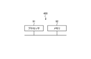
- FIG. 5 is a diagram showing an example of a hardware configuration that implements the control unit 400 included in the power converter 1 according to Embodiment 1. As shown in FIG. The control unit 400 is implemented by the processor 91 and memory 92 .
- the processor 91 is a CPU (Central Processing Unit, central processing unit, processing unit, arithmetic unit, microprocessor, microcomputer, processor, DSP (Digital Signal Processor)), or a system LSI (Large Scale Integration).
- the memory 92 includes RAM (Random Access Memory), ROM (Read Only Memory), flash memory, EPROM (Erasable Programmable Read Only Memory), EEPROM (registered trademark) (Electrically Erasable Programmable Read Non-volatile or volatile such as Only Memory)
- RAM Random Access Memory
- ROM Read Only Memory
- flash memory flash memory
- EPROM Erasable Programmable Read Only Memory
- EEPROM registered trademark
- a semiconductor memory can be exemplified.
- the memory 92 is not limited to these, and may be a magnetic disk, an optical disk, a compact disk, a mini disk, or a DVD (Digital Versatile Disc).
- the second AC power including pulsation corresponding to the pulsation of the power flowing into the capacitor 210 from the rectifier 130 is output from the inverter 310 to the motor 314.
- the operation of the inverter 310 is controlled so that the current flowing through the capacitor 210 is suppressed.
- This control reduces the stress on the capacitor 210 and suppresses deterioration of the capacitor 210 .
- the capacity of the capacitor 210 can be reduced, or a capacitor 210 with a small resistance to deterioration due to ripples can be used, so that the power conversion device 1 can be suppressed from increasing in size.
- the pulsation of the pulsating current due to the second AC power depends on whether the operation of the refrigeration cycle applied equipment is the cooling operation or the heating operation. It works so that the width can be different values. According to the refrigerating cycle applied equipment equipped with the power conversion device 1 that operates in this manner, it is possible to perform cooling operation, heating operation, and operation suitable for temperature environmental conditions. As a result, the refrigeration cycle applied equipment can be stably operated.
- FIG. 6 is a diagram showing a configuration example of a refrigeration cycle application device 900 according to Embodiment 2.
- a refrigerating cycle-applied equipment 900 according to the second embodiment includes the power converter 1 described in the first embodiment.
- the refrigerating cycle applied equipment 900 according to Embodiment 2 can be applied to products equipped with a refrigerating cycle, such as air conditioners, refrigerators, freezers, and heat pump water heaters.
- constituent elements having functions similar to those of the first embodiment are denoted by the same reference numerals as those of the first embodiment.
- Refrigerating cycle applied equipment 900 includes compressor 315 incorporating motor 314 according to Embodiment 1, four-way valve 902, indoor heat exchanger 906, expansion valve 908, and outdoor heat exchanger 910 with refrigerant pipe 912. attached through
- a compression mechanism 904 that compresses the refrigerant and a motor 314 that operates the compression mechanism 904 are provided inside the compressor 315 .
- the refrigeration cycle applied equipment 900 can perform heating operation or cooling operation by switching operation of the four-way valve 902 .
- the compression mechanism 904 is driven by a variable speed controlled motor 314 .
- the refrigerant is pressurized by the compression mechanism 904 and sent out through the four-way valve 902, the indoor heat exchanger 906, the expansion valve 908, the outdoor heat exchanger 910, and the four-way valve 902. Return to compression mechanism 904 .
- the refrigerant is pressurized by the compression mechanism 904 and sent through the four-way valve 902, the outdoor heat exchanger 910, the expansion valve 908, the indoor heat exchanger 906, and the four-way valve 902. Return to compression mechanism 904 .
- the indoor heat exchanger 906 acts as a condenser to release heat, and the outdoor heat exchanger 910 acts as an evaporator to absorb heat.
- the outdoor heat exchanger 910 acts as a condenser to release heat, and the indoor heat exchanger 906 acts as an evaporator to absorb heat.
- the expansion valve 908 reduces the pressure of the refrigerant to expand it.
- the configuration shown in the above embodiment shows an example, and can be combined with another known technique, and part of the configuration can be omitted or changed without departing from the scope of the invention. is also possible. Further, the operation shown in the above embodiment is also an example, and it is possible to combine the above-described first to third operation modes, and another known operation mode is possible without departing from the scope of the invention. It is also possible to combine with the technology of
Abstract
A power conversion device (1) to be mounted to refrigeration cycle application equipment comprises: a rectifying unit (130) that rectifies first AC power supplied from a commercial power supply (110); a capacitor (210) that is connected to an output end of the rectifying unit (130); an inverter (310) that converts power outputted from the rectifying unit (130) and the capacitor (210) into second AC power and outputs the same to a motor (314); and a control unit (400) that controls the operation of the inverter (310) so as to output, from the inverter (310), the second AC power which includes pulsation corresponding to the pulsation of power flowing from the rectifying unit (130) into the capacitor (210), and that suppresses the current flowing to the capacitor (210). The power conversion device (1) operates, in a state of receiving predetermined power from the commercial power supply (110), such that the pulsation width of pulsating current due to the second AC power becomes different values depending on whether the operation of the refrigeration cycle application equipment is a cooling operation or a heating operation.
Description
本開示は、交流電力を所望の電力に変換する電力変換装置、モータ駆動装置及び冷凍サイクル適用機器に関する。
The present disclosure relates to a power conversion device, a motor drive device, and a refrigeration cycle application device that convert AC power into desired power.
従来、交流電源から供給される交流電力を所望の交流電力に変換し、空気調和機などの負荷に供給する電力変換装置がある。例えば、特許文献1には、空気調和機の制御装置である電力変換装置が、交流電源から供給される交流電力を整流部であるダイオードスタックで整流し、さらに平滑コンデンサで平滑した電力を、複数のスイッチング素子からなるインバータで所望の交流電力に変換し、負荷である圧縮機モータに出力する技術が開示されている。
Conventionally, there is a power conversion device that converts AC power supplied from an AC power supply into desired AC power and supplies it to a load such as an air conditioner. For example, in Patent Document 1, a power converter, which is a control device for an air conditioner, rectifies AC power supplied from an AC power supply with a diode stack, which is a rectifier, and smoothes the power with a smoothing capacitor. A technology is disclosed in which the AC power is converted into a desired AC power by an inverter composed of switching elements and output to a compressor motor, which is a load.
しかしながら、上記従来の技術によれば、平滑コンデンサに大きな電流が流れるため、平滑コンデンサの経年劣化が加速する、という問題があった。このような問題に対して、平滑コンデンサの容量を大きくすることでコンデンサ電圧のリプル変化を抑制する、又はリプルによる劣化耐量の大きい平滑コンデンサを使用する方法が考えられるが、コンデンサ部品のコストが高くなり、また装置が大型化してしまう。
However, according to the above conventional technology, a large current flows through the smoothing capacitor, so there is a problem that aging deterioration of the smoothing capacitor is accelerated. As a solution to this problem, it is conceivable to increase the capacity of the smoothing capacitor to suppress the ripple change in the capacitor voltage, or to use a smoothing capacitor with a high resistance to deterioration due to ripple. , and the size of the apparatus becomes large.
本開示は、上記に鑑みてなされたものであって、平滑用のコンデンサの劣化を抑制しつつ、装置の大型化を抑制可能な電力変換装置を得ることを目的とする。
The present disclosure has been made in view of the above, and an object thereof is to obtain a power conversion device capable of suppressing an increase in device size while suppressing deterioration of a smoothing capacitor.
上述した課題を解決し、目的を達成するために、本開示に係る電力変換装置は、冷凍サイクル適用機器に搭載される電力変換装置であって、整流部と、整流部の出力端に接続されるコンデンサと、コンデンサの両端に接続されるインバータと、制御部とを備える。整流部は、交流電源から供給される第1の交流電力を整流する。インバータは、整流部及びコンデンサから出力される電力を第2の交流電力に変換し、モータを有する負荷に出力する。制御部は、整流部からコンデンサに流入する電力の脈動に応じた脈動を含む第2の交流電力がインバータから負荷に出力されるようにインバータの動作を制御し、コンデンサに流れる電流を抑制する。電力変換装置は、予め定められた電力を交流電源から受電する状態において、冷凍サイクル適用機器の動作が冷房動作であるか暖房動作であるかによって、第2の交流電力による脈動電流の脈動幅が異なる値となるように動作する。
In order to solve the above-described problems and achieve the object, a power conversion device according to the present disclosure is a power conversion device mounted on a refrigeration cycle application device, and is connected to a rectification section and an output end of the rectification section. an inverter connected to both ends of the capacitor; and a controller. The rectifier rectifies first AC power supplied from an AC power supply. The inverter converts the power output from the rectifier and the capacitor into second AC power, and outputs the second AC power to a load having a motor. The control unit controls the operation of the inverter so that the second AC power including pulsation corresponding to the pulsation of the power flowing into the capacitor from the rectifying unit is output from the inverter to the load, thereby suppressing the current flowing through the capacitor. In the power converter, in a state of receiving predetermined power from the AC power supply, the pulsation width of the pulsating current generated by the second AC power varies depending on whether the operation of the refrigeration cycle device is cooling operation or heating operation. It behaves like a different value.
本開示に係る電力変換装置は、平滑用のコンデンサの劣化を抑制しつつ、装置の大型化を抑制できる、という効果を奏する。
The power converter according to the present disclosure has the effect of suppressing the deterioration of the smoothing capacitor and suppressing the enlargement of the device.
以下に、本開示の実施の形態に係る電力変換装置、モータ駆動装置及び冷凍サイクル適用機器を図面に基づいて詳細に説明する。
A power conversion device, a motor drive device, and a refrigeration cycle application device according to an embodiment of the present disclosure will be described below in detail based on the drawings.
実施の形態1.
図1は、実施の形態1に係る電力変換装置1の構成例を示す図である。電力変換装置1は、商用電源110及び圧縮機315に接続される。商用電源110は、交流電源の例示である。電力変換装置1は、商用電源110から供給される電源電圧Vsの第1の交流電力を所望の振幅及び位相を有する第2の交流電力に変換し、圧縮機315に供給する。電力変換装置1は、電圧電流検出部501と、リアクトル120と、整流部130と、電圧検出部502と、平滑部200と、インバータ310と、電流検出部313a,313bと、温度検出部504と、制御部400と、を備える。なお、電力変換装置1、及び圧縮機315が備えるモータ314によって、モータ駆動装置2が構成される。また、電力変換装置1は、後述する冷凍サイクル適用機器に搭載可能に構成される。 Embodiment 1.
FIG. 1 is a diagram showing a configuration example of a power conversion device 1 according to Embodiment 1. As shown in FIG. The power converter 1 is connected to acommercial power source 110 and a compressor 315 . Commercial power supply 110 is an example of an AC power supply. The power conversion device 1 converts first AC power of power supply voltage Vs supplied from the commercial power supply 110 into second AC power having desired amplitude and phase, and supplies the second AC power to the compressor 315 . The power conversion device 1 includes a voltage/current detection unit 501, a reactor 120, a rectification unit 130, a voltage detection unit 502, a smoothing unit 200, an inverter 310, current detection units 313a and 313b, and a temperature detection unit 504. , and a control unit 400 . A motor drive device 2 is configured by the power conversion device 1 and the motor 314 included in the compressor 315 . Moreover, the power conversion device 1 is configured to be mountable on a refrigeration cycle application device, which will be described later.
図1は、実施の形態1に係る電力変換装置1の構成例を示す図である。電力変換装置1は、商用電源110及び圧縮機315に接続される。商用電源110は、交流電源の例示である。電力変換装置1は、商用電源110から供給される電源電圧Vsの第1の交流電力を所望の振幅及び位相を有する第2の交流電力に変換し、圧縮機315に供給する。電力変換装置1は、電圧電流検出部501と、リアクトル120と、整流部130と、電圧検出部502と、平滑部200と、インバータ310と、電流検出部313a,313bと、温度検出部504と、制御部400と、を備える。なお、電力変換装置1、及び圧縮機315が備えるモータ314によって、モータ駆動装置2が構成される。また、電力変換装置1は、後述する冷凍サイクル適用機器に搭載可能に構成される。 Embodiment 1.
FIG. 1 is a diagram showing a configuration example of a power conversion device 1 according to Embodiment 1. As shown in FIG. The power converter 1 is connected to a
電圧電流検出部501は、商用電源110から供給される電源電圧Vsの第1の交流電力の電圧値及び電流値を検出し、検出した電圧値及び電流値を制御部400に出力する。リアクトル120は、電圧電流検出部501と整流部130との間に接続される。
The voltage/current detection unit 501 detects the voltage value and current value of the first AC power of the power supply voltage Vs supplied from the commercial power supply 110 and outputs the detected voltage value and current value to the control unit 400 . Reactor 120 is connected between voltage/current detection unit 501 and rectification unit 130 .
整流部130は、整流素子131~134によって構成されるブリッジ回路を有し、商用電源110から供給される電源電圧Vsの第1の交流電力を整流して出力する。整流部130は、全波整流を行う。
The rectifying section 130 has a bridge circuit composed of rectifying elements 131 to 134, rectifies the first AC power of the power supply voltage Vs supplied from the commercial power supply 110, and outputs it. The rectifier 130 performs full-wave rectification.
電圧検出部502は、整流部130によって整流された電力の電圧値を検出し、検出した電圧値を制御部400に出力する。
The voltage detection section 502 detects the voltage value of the power rectified by the rectification section 130 and outputs the detected voltage value to the control section 400 .
平滑部200は、電圧検出部502を介して整流部130の出力端に接続される。平滑部200は、平滑素子としてコンデンサ210を有し、整流部130によって整流された電力を平滑化する。
The smoothing section 200 is connected to the output terminal of the rectifying section 130 via the voltage detecting section 502 . Smoothing section 200 has capacitor 210 as a smoothing element, and smoothes the power rectified by rectifying section 130 .
コンデンサ210は、例えば、電解コンデンサ、フィルムコンデンサなどである。コンデンサ210は、整流部130によって整流された電力を平滑化する容量を有する。平滑化によりコンデンサ210に発生する電圧は、商用電源110の全波整流波形形状ではなく、直流成分に商用電源110の周波数に応じた電圧リプルが重畳した波形形状となり、大きく脈動しない。この電圧リプルの周波数は、商用電源110が単相の場合は電源電圧Vsの周波数の2倍成分となり、商用電源110が三相の場合は6倍成分が主成分となる。商用電源110から入力される電力とインバータ310から出力される電力が変化しない場合、電圧リプルの振幅はコンデンサ210の容量によって決まる。電圧リプルの振幅は、例えば、コンデンサ210に発生する電圧リプルの最大値が最小値の2倍未満となるような範囲で脈動している。
The capacitor 210 is, for example, an electrolytic capacitor, a film capacitor, or the like. Capacitor 210 has a capacity to smooth the power rectified by rectifying section 130 . The voltage generated in the capacitor 210 by smoothing does not have a full-wave rectified waveform of the commercial power supply 110, but has a waveform in which a voltage ripple corresponding to the frequency of the commercial power supply 110 is superimposed on the DC component, and does not greatly pulsate. The frequency of this voltage ripple is a component twice the frequency of the power supply voltage Vs when the commercial power supply 110 is single-phase, and the main component is a frequency component six times the frequency of the power supply voltage Vs when the commercial power supply 110 is three-phase. If the power input from commercial power supply 110 and the power output from inverter 310 do not change, the amplitude of the voltage ripple is determined by the capacitance of capacitor 210 . The amplitude of the voltage ripple pulsates, for example, within a range such that the maximum value of the voltage ripple generated in capacitor 210 is less than twice the minimum value.
インバータ310は、平滑部200、即ちコンデンサ210の両端に接続される。インバータ310は、スイッチング素子311a~311f、及び還流ダイオード312a~312fを有する。インバータ310は、制御部400の制御によってスイッチング素子311a~311fをオンオフし、整流部130及び平滑部200から出力される電力を所望の振幅及び位相を有する第2の交流電力に変換して、圧縮機315に出力する。
The inverter 310 is connected to both ends of the smoothing section 200 , that is, the capacitor 210 . The inverter 310 has switching elements 311a-311f and freewheeling diodes 312a-312f. The inverter 310 turns on and off the switching elements 311a to 311f under the control of the control unit 400, converts the power output from the rectifying unit 130 and the smoothing unit 200 into second AC power having desired amplitude and phase, and compresses the power. output to machine 315.
電流検出部313a,313bは、各々がインバータ310から出力される3相の電流のうち1相の電流値を検出し、検出した電流値を制御部400に出力する。なお、制御部400は、インバータ310から出力される3相の電流値のうち2相の電流値を取得することで、インバータ310から出力される残りの1相の電流値を算出することができる。
Each of the current detection units 313 a and 313 b detects the current value of one of the three phase currents output from the inverter 310 and outputs the detected current value to the control unit 400 . Control unit 400 acquires two-phase current values among the three-phase current values output from inverter 310, thereby calculating the remaining one-phase current value output from inverter 310. .
温度検出部504は、コンデンサ210の温度又はコンデンサ210の周囲温度を検出し、検出した温度値を制御部400に出力する。なお、一般的な電力変換装置の場合、制御基板又は回路基板には温度検出器が設けられている。このため、温度検出部504を設けることなく、当該基板に設けられた温度検出器の検出値で代用してもよい。
The temperature detection unit 504 detects the temperature of the capacitor 210 or the ambient temperature of the capacitor 210 and outputs the detected temperature value to the control unit 400 . In addition, in the case of a general power conversion device, a temperature detector is provided on the control board or the circuit board. Therefore, instead of providing the temperature detection unit 504, the detected value of the temperature detector provided on the substrate may be used instead.
圧縮機315は、圧縮機駆動用のモータ314を有する負荷である。モータ314は、インバータ310から供給される第2の交流電力の振幅及び位相に応じて回転し、圧縮動作を行う。例えば、圧縮機315が空気調和機などで使用される密閉型圧縮機の場合、圧縮機315の負荷トルクは定トルク負荷とみなせる場合が多い。
A compressor 315 is a load having a motor 314 for driving the compressor. The motor 314 rotates according to the amplitude and phase of the second AC power supplied from the inverter 310 and performs compression operation. For example, when the compressor 315 is a hermetic compressor used in an air conditioner or the like, the load torque of the compressor 315 can often be regarded as a constant torque load.
なお、電力変換装置1において、図1に示す各構成の配置は一例であり、各構成の配置は図1で示される例に限定されない。例えば、リアクトル120は、整流部130の後段に配置されてもよい。以降の説明において、電圧電流検出部501、電圧検出部502、及び電流検出部313a,313bをまとめて検出部と称することがある。また、電圧電流検出部501で検出された電圧値及び電流値、電圧検出部502で検出された電圧値、及び電流検出部313a,313bで検出された電流値を、検出値と称することがある。
In addition, in the power converter 1, the arrangement of each configuration shown in FIG. 1 is an example, and the arrangement of each configuration is not limited to the example shown in FIG. For example, reactor 120 may be arranged after rectifying section 130 . In the following description, the voltage/current detector 501, the voltage detector 502, and the current detectors 313a and 313b may be collectively referred to as detectors. Also, the voltage value and current value detected by the voltage/current detection unit 501, the voltage value detected by the voltage detection unit 502, and the current values detected by the current detection units 313a and 313b may be referred to as detection values. .
制御部400は、電圧電流検出部501から第1の交流電力の電圧値及び電流値を取得し、電圧検出部502から整流部130によって整流された電力の電圧値を取得する。また、制御部400は、電流検出部313a,313bからインバータ310によって変換された所望の振幅及び位相を有する第2の交流電力の電流値を取得し、温度検出部504からコンデンサ210の温度又は周囲温度の温度値を取得する。制御部400は、各検出部によって検出された検出値を用いて、インバータ310の動作、具体的には、インバータ310が有するスイッチング素子311a~311fのオンオフを制御する。なお、制御部400は、各検出部から取得した全ての検出値を用いなくてもよく、一部の検出値を用いて制御を行うことができる。
The control unit 400 acquires the voltage value and current value of the first AC power from the voltage/current detection unit 501 and acquires the voltage value of the power rectified by the rectification unit 130 from the voltage detection unit 502 . In addition, the control unit 400 acquires the current value of the second AC power having the desired amplitude and phase converted by the inverter 310 from the current detection units 313a and 313b, and the temperature of the capacitor 210 or the ambient temperature from the temperature detection unit 504 Get the temperature value of the temperature. Control unit 400 controls the operation of inverter 310, specifically, the on/off of switching elements 311a to 311f included in inverter 310, using the detection values detected by the respective detection units. Note that the control unit 400 does not have to use all the detection values acquired from each detection unit, and can perform control using some of the detection values.
実施の形態1において、制御部400は、第2の交流電力による脈動電流によって、平滑部200のコンデンサ210に流れる電流を制御する。具体的に、制御部400は、整流部130から平滑部200のコンデンサ210に流入する電力の脈動に応じた脈動を含む第2の交流電力がインバータ310から負荷である圧縮機315に出力されるようにインバータ310の動作を制御する。ここで、平滑部200のコンデンサ210に流入する電力の脈動に応じた脈動とは、例えば、平滑部200のコンデンサ210に流入する電力の脈動の周波数などによって変動する脈動である。これにより、制御部400は、平滑部200のコンデンサ210に流れる電流を抑制する。
In Embodiment 1, the control unit 400 controls the current flowing through the capacitor 210 of the smoothing unit 200 with the pulsating current generated by the second AC power. Specifically, the control unit 400 causes the inverter 310 to output the second AC power including the pulsation corresponding to the pulsation of the power flowing into the capacitor 210 of the smoothing unit 200 from the rectifying unit 130 to the compressor 315 which is the load. The operation of inverter 310 is controlled as follows. Here, the pulsation according to the pulsation of the power flowing into the capacitor 210 of the smoothing section 200 is, for example, the pulsation that varies depending on the frequency of the pulsation of the power flowing into the capacitor 210 of the smoothing section 200 . Thereby, the control unit 400 suppresses the current flowing through the capacitor 210 of the smoothing unit 200 .
次に、電力変換装置1が備える制御部400の動作について説明する。なお、実施の形態1に係る電力変換装置1において、インバータ310及び圧縮機315によって発生する負荷は一定の負荷とみなすことができる。このため、本稿では、電力変換装置1においては、平滑部200から出力される電流で見た場合、平滑部200に定電流負荷が接続されているものとして、以降の説明を行う。
Next, the operation of the control unit 400 included in the power converter 1 will be described. In addition, in the power converter 1 according to Embodiment 1, the load generated by the inverter 310 and the compressor 315 can be regarded as a constant load. For this reason, in this paper, the following description will be made on the assumption that a constant current load is connected to the smoothing section 200 in terms of the current output from the smoothing section 200 in the power converter 1 .
ここで、図1に示すように、整流部130から流れる電流を電流I1とし、インバータ310に流れる電流を電流I2とし、平滑部200から流れる電流を電流I3とする。電流I2は、電流I1と電流I3とを併せた電流となる。電流I3は、電流I2と電流I1との差分、即ち電流I2-電流I1による電流として表すことができる。電流I3は、平滑部200の放電方向を正方向とし、平滑部200の充電方向を負方向とする。即ち、平滑部200には、電流が流入することもあり、電流が流出することもある。
Here, as shown in FIG. 1, the current flowing from the rectifying section 130 is current I1, the current flowing to the inverter 310 is current I2, and the current flowing from the smoothing section 200 is current I3. The current I2 is the sum of the currents I1 and I3. The current I3 can be expressed as the difference between the currents I2 and I1, that is, the current resulting from the current I2 minus the current I1. The current I3 has a positive direction in the discharging direction of the smoothing section 200 and a negative direction in the charging direction of the smoothing section 200 . That is, current may flow into or out of the smoothing section 200 .
図2は、比較例として、平滑部200で整流部130から出力される電流を平滑化し、インバータ310に流れる電流I2を一定にした場合の各電流I1~I3及び平滑部200のコンデンサ210のコンデンサ電圧Vdcの例を示す図である。上から順に、電流I1、電流I2、電流I3、及び電流I3に応じて発生するコンデンサ210のコンデンサ電圧Vdcを示している。電流I1,I2,I3の縦軸は電流値を示し、コンデンサ電圧Vdcの縦軸は電圧値を示している。横軸は全て時間tを示している。なお、電流I2,I3には、実際にはインバータ310のキャリア成分が重畳されるが、ここでは省略する。以降についても同様とする。
FIG. 2 shows, as a comparative example, the currents I1 to I3 and the capacitor 210 of the smoothing unit 200 when the current output from the rectifying unit 130 is smoothed by the smoothing unit 200 and the current I2 flowing through the inverter 310 is kept constant. FIG. 4 is a diagram showing an example of voltage Vdc; The current I1, the current I2, the current I3, and the capacitor voltage Vdc of the capacitor 210 generated according to the current I3 are shown in order from the top. The vertical axis of currents I1, I2, and I3 indicates current values, and the vertical axis of capacitor voltage Vdc indicates voltage values. All horizontal axes indicate time t. Although the currents I2 and I3 are actually superimposed with the carrier component of the inverter 310, they are omitted here. The same shall apply to the following.
図2に示すように、電力変換装置1において、仮に、整流部130から流れる電流I1が平滑部200によって十分に平滑化された場合、インバータ310に流れる電流I2は一定の電流値となる。しかしながら、平滑部200のコンデンサ210には、大きな電流I3が流れ、コンデンサ210の劣化の要因となる。そのため、実施の形態1では、電力変換装置1において、制御部400は、平滑部200に流れる電流I3が低減されるように、インバータ310に流れる電流I2を制御、即ちインバータ310の動作を制御する。
As shown in FIG. 2, in the power converter 1, if the current I1 flowing from the rectifying section 130 is sufficiently smoothed by the smoothing section 200, the current I2 flowing through the inverter 310 has a constant current value. However, a large current I3 flows through the capacitor 210 of the smoothing unit 200, which causes deterioration of the capacitor 210. FIG. Therefore, in the first embodiment, in the power conversion device 1, the control unit 400 controls the current I2 flowing through the inverter 310 so that the current I3 flowing through the smoothing unit 200 is reduced, that is, controls the operation of the inverter 310. .
図3は、実施の形態1に係る電力変換装置1の制御部400がインバータ310の動作を制御して平滑部200に流れる電流I3を低減したときの各電流I1~I3及び平滑部200のコンデンサ210のコンデンサ電圧Vdcの例を示す図である。上から順に、電流I1、電流I2、電流I3、及び電流I3に応じて発生するコンデンサ210のコンデンサ電圧Vdcを示している。電流I1,I2,I3の縦軸は電流値を示し、コンデンサ電圧Vdcの縦軸は電圧値を示している。横軸は全て時間tを示している。電力変換装置1の制御部400は、図3に示すような電流I2がインバータ310に流れるようにインバータ310の動作を制御する。この制御により、図2の例と比較して、整流部130から平滑部200に流れ込む電流が低減され、その結果、平滑部200に流れる電流I3が低減される。具体的に、制御部400は、電流I1の周波数成分を主成分とした脈動電流を含む電流I2がインバータ310に流れるようにインバータ310の動作を制御する。
FIG. 3 shows the respective currents I1 to I3 and the capacitor of the smoothing unit 200 when the control unit 400 of the power converter 1 according to Embodiment 1 controls the operation of the inverter 310 to reduce the current I3 flowing through the smoothing unit 200. 210 is a diagram showing an example of the capacitor voltage Vdc of 210. FIG. The current I1, the current I2, the current I3, and the capacitor voltage Vdc of the capacitor 210 generated according to the current I3 are shown in order from the top. The vertical axis of currents I1, I2, and I3 indicates current values, and the vertical axis of capacitor voltage Vdc indicates voltage values. All horizontal axes indicate time t. The control unit 400 of the power converter 1 controls the operation of the inverter 310 so that the current I2 shown in FIG. This control reduces the current flowing from the rectifying section 130 to the smoothing section 200 as compared with the example of FIG. 2, and as a result, the current I3 flowing to the smoothing section 200 is reduced. Specifically, control unit 400 controls the operation of inverter 310 so that current I2 containing a pulsating current whose main component is the frequency component of current I1 flows through inverter 310 .
電流I1の周波数成分は、商用電源110から供給される交流電流の周波数、及び整流部130の構成によって決定される。そのため、制御部400は、電流I2に重畳する脈動電流の周波数成分を、予め定めた振幅及び位相を有する成分とすることができる。電流I2に重畳される脈動電流の周波数成分は、電流I1の周波数成分の相似波形となる。制御部400は、電流I2に重畳する脈動電流の周波数成分を電流I1の周波数成分に近付けていくに連れて、平滑部200に流れる電流I3を低減し、コンデンサ電圧Vdcに発生する脈動電圧を低減することができる。
The frequency component of the current I1 is determined by the frequency of the alternating current supplied from the commercial power supply 110 and the configuration of the rectifying section 130. Therefore, the control unit 400 can make the frequency component of the pulsating current superimposed on the current I2 a component having a predetermined amplitude and phase. The frequency component of the pulsating current superimposed on the current I2 has a waveform similar to that of the current I1. As the frequency component of the pulsating current superimposed on the current I2 approaches the frequency component of the current I1, the control unit 400 reduces the current I3 flowing through the smoothing unit 200 and reduces the pulsating voltage generated in the capacitor voltage Vdc. can do.
制御部400が、インバータ310の動作を制御することによってインバータ310に流れる電流の脈動を制御することは、インバータ310から圧縮機315に出力される第2の交流電力による脈動電流を制御することと等価である。制御部400は、インバータ310から出力される第2の交流電力による脈動電流が、整流部130から出力される電力による脈動電流よりも脈動量、即ち脈動電流の脈動幅が小さくなるようにインバータ310の動作を制御する。
Controlling the pulsation of the current flowing through inverter 310 by controlling the operation of inverter 310 by control unit 400 means controlling the pulsating current due to the second AC power output from inverter 310 to compressor 315 . are equivalent. The control unit 400 controls the inverter 310 so that the amount of pulsating current generated by the second AC power output from the inverter 310 is smaller than the pulsating current generated by the power output from the rectifying unit 130, that is, the pulsating width of the pulsating current. controls the behavior of
制御部400は、コンデンサ210に流出入する電流の脈動が、インバータ310から出力される第2の交流電力にコンデンサ210に流入する電力の脈動に応じた脈動が含まれないときのコンデンサ210に発生する電流の脈動よりも小さくなるように、インバータ310から出力される第2の交流電力による脈動電流の脈動幅を制御する。或いは、制御部400は、コンデンサ電圧Vdcの電圧の脈動、即ちコンデンサ210に発生する電圧の脈動が、インバータ310から出力される第2の交流電力にコンデンサ210に流入する電力の脈動に応じた脈動電力が含まれないときのコンデンサ210に発生する電圧の脈動よりも小さくなるように、インバータ310から出力される第2の交流電力による脈動電流の脈動幅を制御する。なお、インバータ310から出力される第2の交流電力にコンデンサ210に流入する電力の脈動に応じた脈動が含まれないときとは、図2に示すような制御のことである。また、脈動幅は、脈動電流の最大値と最小値との差分である。
The control unit 400 controls the pulsation of the current flowing into and out of the capacitor 210 when the pulsation corresponding to the pulsation of the power flowing into the capacitor 210 is not included in the second AC power output from the inverter 310 . The pulsating width of the pulsating current due to the second AC power output from the inverter 310 is controlled so as to be smaller than the pulsating current. Alternatively, the control unit 400 controls the pulsation of the voltage of the capacitor voltage Vdc, that is, the pulsation of the voltage generated in the capacitor 210 to cause the second AC power output from the inverter 310 to pulsate according to the pulsation of the power flowing into the capacitor 210. The pulsating width of the pulsating current due to the second AC power output from inverter 310 is controlled so as to be smaller than the pulsating voltage generated in capacitor 210 when no power is included. The control shown in FIG. 2 means that the second AC power output from inverter 310 does not include pulsation corresponding to the pulsation of the power flowing into capacitor 210 . Also, the pulsation width is the difference between the maximum value and the minimum value of the pulsation current.
上述した制御は「電源脈動補償制御」と呼ばれる。即ち、電源脈動補償制御は、電源脈動に起因して平滑部200のコンデンサ210に流れ得るリプル電流を抑制する制御である。電源脈動補償制御によれば、電源脈動に起因するリプル電流の多くがコンデンサ210をスルーして負荷に供給される。このため、電源脈動補償制御を用いれば、コンデンサ210のストレスを軽減して、コンデンサ210の劣化を抑制することができる。
The control described above is called "power supply ripple compensation control". That is, the power supply ripple compensation control is control for suppressing the ripple current that may flow through the capacitor 210 of the smoothing section 200 due to the power supply ripple. According to the power supply ripple compensation control, most of the ripple current caused by the power supply ripple passes through the capacitor 210 and is supplied to the load. Therefore, by using the power supply ripple compensation control, the stress on the capacitor 210 can be reduced and the deterioration of the capacitor 210 can be suppressed.
なお、商用電源110から供給される交流電流については、特に限定されず、単相であってもよいし、3相であってもよい。制御部400は、電流I2に重畳する脈動電流の周波数成分について、商用電源110から供給される第1の交流電力に応じて決定すればよい。具体的に、制御部400は、インバータ310に流れる電流I2の脈動波形を、商用電源110から供給される第1の交流電力が単相の場合は第1の交流電力の周波数の2倍の周波数成分、又は商用電源110から供給される第1の交流電力が3相の場合は第1の交流電力の周波数の6倍の周波数成分を主成分とする脈動波形に直流分を加算した形状に制御する。脈動波形は、例えば、正弦波の絶対値の形状、又は正弦波の形状とする。この場合、制御部400は、正弦波の周波数の整数倍の成分のうち少なくとも1つの周波数成分を予め規定された振幅として脈動波形に加算してもよい。また、脈動波形は、矩形波の形状、又は三角波の形状であってもよい。この場合、制御部400は、脈動波形の振幅及び位相を予め規定された値としてもよい。
The alternating current supplied from the commercial power supply 110 is not particularly limited, and may be single-phase or three-phase. Control unit 400 may determine the frequency component of the pulsating current superimposed on current I2 according to the first AC power supplied from commercial power supply 110 . Specifically, when the first AC power supplied from commercial power supply 110 is single-phase, control unit 400 sets the pulsating waveform of current I2 flowing in inverter 310 to a frequency that is twice the frequency of the first AC power. component, or when the first AC power supplied from the commercial power supply 110 is three-phase, the pulsation waveform having a frequency component six times the frequency of the first AC power as the main component is controlled to a shape obtained by adding a DC component to the waveform. do. The pulsation waveform is, for example, the shape of the absolute value of a sine wave or the shape of a sine wave. In this case, the control unit 400 may add at least one frequency component of integral multiples of the sine wave frequency to the pulsating waveform as a predetermined amplitude. Also, the pulsating waveform may be in the shape of a rectangular wave or in the shape of a triangular wave. In this case, the control unit 400 may set the amplitude and phase of the pulsation waveform to predetermined values.
制御部400は、コンデンサ210に印加される電圧又はコンデンサ210に流れる電流を用いて、インバータ310から出力される第2の交流電力による脈動電流の脈動量を演算してもよいし、商用電源110から供給される第1の交流電力の電圧又は電流を用いて、インバータ310から出力される第2の交流電力による脈動電流の脈動量を演算してもよい。
The control unit 400 may use the voltage applied to the capacitor 210 or the current flowing through the capacitor 210 to calculate the amount of pulsation of the pulsating current due to the second AC power output from the inverter 310 . The amount of pulsation of the pulsating current due to the second AC power output from the inverter 310 may be calculated using the voltage or current of the first AC power supplied from the inverter 310 .
次に、電力変換装置1が冷凍サイクル適用機器に搭載された場合における、制御部400の動作について、フローチャートを用いて説明する。図4は、実施の形態1に係る電力変換装置1が備える制御部400の動作を示すフローチャートである。
Next, the operation of the control unit 400 when the power conversion device 1 is mounted on a refrigeration cycle application device will be described using a flowchart. FIG. 4 is a flow chart showing the operation of the control unit 400 included in the power conversion device 1 according to the first embodiment.
制御部400は、電力変換装置1の各検出部から、所要の検出値を取得する(ステップS11)。制御部400は、冷凍サイクル適用機器の動作が冷房動作であるか、暖房動作であるかを確認する(ステップS12)。制御部400は、冷房動作又は暖房動作であるかに応じて、第2の交流電力による脈動電流の脈動幅を適切に制御する(ステップS13)。
The control unit 400 acquires required detection values from each detection unit of the power converter 1 (step S11). The control unit 400 confirms whether the operation of the refrigeration cycle equipment is cooling operation or heating operation (step S12). The control unit 400 appropriately controls the pulsation width of the pulsating current generated by the second AC power depending on whether the operation is cooling operation or heating operation (step S13).
なお、図4のフローチャートには、種々の動作態様が含まれる。まず、実施の形態1における第1の動作態様について説明する。第1の動作態様は、予め定められた電力を商用電源110から受電する状態において、冷凍サイクル適用機器の動作が冷房動作であるか暖房動作であるかによって、第2の交流電力による脈動電流の脈動幅が異なる値となる動作態様である。なお、本稿では、冷凍サイクル適用機器のヒートポンプ装置を冷房サイクルで動作させることを「冷房動作」と呼び、冷凍サイクル適用機器のヒートポンプ装置を暖房サイクルで動作させることを「暖房動作」と呼ぶ。
It should be noted that the flowchart of FIG. 4 includes various operation modes. First, a first operation mode in Embodiment 1 will be described. In the first operation mode, in a state where predetermined power is received from commercial power supply 110, the pulsating current generated by the second AC power depends on whether the operation of the refrigeration cycle device is cooling operation or heating operation. This is an operation mode in which the pulsation widths have different values. In this paper, operating the heat pump device of the refrigeration cycle equipment in the cooling cycle is called "cooling operation", and operating the heat pump device of the refrigeration cycle equipment in the heating cycle is called "heating operation".
例えば、インバータ310からモータ314に出力される第2の交流電力による脈動電流の脈動幅が、暖房動作時よりも冷房動作時の方が大きくなるようにインバータ310の動作を制御することが考えられる。一般的に、冷房動作時の方が冷凍サイクル適用機器における周囲温度が高く、コンデンサ210の寿命劣化が促進される状態にある。従って、暖房動作時よりも冷房動作時の方が脈動電流の脈動幅が大きくなるように制御、逆に言うと、冷房動作時よりも暖房動作時の方が脈動電流の脈動幅が小さくなるように制御すれば、外気温が高い冷房動作時において、電源脈動補償制御を強く効かせることができる。その結果、温度環境が厳しい冷房条件において、コンデンサ電流の低減を効果的に行うことができ、コンデンサ210の自己発熱を抑制することができる。これにより、耐熱温度が低いコンデンサ210の適用が可能となる。
For example, it is conceivable to control the operation of inverter 310 so that the pulsating width of the pulsating current due to the second AC power output from inverter 310 to motor 314 is larger during cooling operation than during heating operation. . Generally, the ambient temperature in the refrigerating cycle equipment is higher during the cooling operation, which accelerates deterioration of the life of the capacitor 210 . Therefore, control is performed so that the pulsating width of the pulsating current is larger during the cooling operation than during the heating operation. , the power supply pulsation compensation control can be strongly effected during cooling operation when the outside air temperature is high. As a result, it is possible to effectively reduce the capacitor current under cooling conditions in which the temperature environment is severe, so that the self-heating of the capacitor 210 can be suppressed. This makes it possible to apply the capacitor 210 with a low heat-resistant temperature.
また、例えば、インバータ310からモータ314に出力される第2の交流電力による脈動電流の脈動幅が、冷房動作時よりも暖房動作時の方が大きくなるようにインバータ310の動作を制御することが考えられる。冷凍サイクル適用機器が空気調和機である場合、寒冷地においては、空気調和機を極低温で暖房動作させる可能性がある。極低温とは、例えば-20℃以下である。コンデンサは、温度の低下と共にキャパシタンスが低下することが一般的に知られている。コンデンサ210のキャパシタンスが大幅に低下すると、空気調和動作を安定的に行うことが困難となる。そこで、冷房動作時よりも暖房動作時の方が脈動電流の脈動幅が大きくなるように制御する。この制御により、外気温が低い暖房動作時において、コンデンサ210を加温することができる。これにより、冷凍サイクル適用機器が極低温の環境下に置かれる場合であっても、冷凍サイクル適用機器を安定的に動作させることが可能となる。
Further, for example, the operation of the inverter 310 can be controlled so that the pulsating width of the pulsating current generated by the second AC power output from the inverter 310 to the motor 314 is larger during the heating operation than during the cooling operation. Conceivable. When the refrigerating cycle application equipment is an air conditioner, there is a possibility that the air conditioner is operated for heating at an extremely low temperature in cold districts. Cryogenic temperatures are, for example, −20° C. or below. Capacitors are generally known to lose capacitance with decreasing temperature. If the capacitance of capacitor 210 drops significantly, it becomes difficult to stably perform the air conditioning operation. Therefore, control is performed so that the pulsating width of the pulsating current is greater during the heating operation than during the cooling operation. This control allows the capacitor 210 to be heated during the heating operation when the outside air temperature is low. As a result, even when the refrigerating cycle applied equipment is placed in an extremely low temperature environment, the refrigerating cycle applied equipment can be stably operated.
以上に説明した第1の動作態様によれば、冷凍サイクル適用機器の動作要求に応じた動作条件を設定できるので、適切なコンデンサ210の保護動作を実現することが可能となる。なお、第1の動作態様によれば、予め定められた電力を商用電源110から受電する状態における冷房動作時及び暖房動作時のうちの少なくとも1つにおいて、第2の交流電力による脈動電流の脈動幅がゼロになることがある。また、第1の動作態様によれば、予め定められた電力を商用電源110から受電する状態において、冷房動作時及び暖房動作時の双方における第2の交流電力による脈動電流の脈動幅が互いにゼロではないことがある。第1の動作態様による制御は、製品の機能、製品の使用場所、又は費用対効果によっては、有用である場合と、有用ではない場合とが考えられる。このため、製品の機能、製品の使用場所又は費用対効果を考慮して、第1の動作態様による制御を採用するか否かを決定することが望ましい。
According to the first operation mode described above, it is possible to set the operation conditions according to the operation request of the refrigeration cycle applied equipment, so that it is possible to realize an appropriate protective operation for the capacitor 210 . Note that, according to the first operation mode, during at least one of the cooling operation and the heating operation in which the predetermined power is received from the commercial power supply 110, the pulsation of the pulsating current due to the second AC power Width can be zero. Further, according to the first operation mode, in a state where predetermined power is received from the commercial power supply 110, the pulsation width of the pulsation current due to the second AC power is zero during both the cooling operation and the heating operation. sometimes not. Control by the first mode of operation may or may not be useful, depending on the product's function, where the product is used, or cost effectiveness. Therefore, it is desirable to decide whether or not to adopt control according to the first mode of operation, taking into consideration the function of the product, the place of use of the product, or cost effectiveness.
次に、実施の形態1における第2の動作態様について説明する。第2の動作態様は、冷凍サイクル適用機器の動作が暖房動作である場合、コンデンサ210の温度又は周囲温度が閾値以下のときには、第2の交流電力による脈動電流の脈動幅を増加させ、又は脈動電流の位相を変化させてコンデンサ210を加温する動作態様である。例えば冷凍サイクル適用機器が空気調和機である場合、外気温が低いとき、及び外気温が高いときの双方において、上述した電源脈動補償制御を外気温が高いときに行われる冷房動作と同様な制御で実施すると、外気温が低いときに行われる暖房動作時において、コンデンサ210の加温が充分に促進されないという問題がある。そこで、コンデンサ210の温度、又はコンデンサ210の周囲温度が閾値以下のときには、第2の交流電力による脈動電流の脈動幅を増大させ、又は脈動電流の位相を変化させてコンデンサ210を積極的に加温する。この制御により、コンデンサ210の発熱が促進される。これにより、冷凍サイクル適用機器が極低温の環境下に置かれる場合であっても、冷凍サイクル適用機器を安定的に動作させることが可能となる。
Next, a second operation mode in Embodiment 1 will be described. In the second operation mode, when the operation of the refrigerating cycle-applied equipment is the heating operation, the pulsation width of the pulsating current generated by the second AC power is increased or This is an operation mode in which the phase of the current is changed to heat the capacitor 210 . For example, when the refrigerating cycle application equipment is an air conditioner, the above-described power supply pulsation compensation control is performed in the same way as the cooling operation performed when the outside temperature is high both when the outside temperature is low and when the outside temperature is high. , there is a problem that the heating of the capacitor 210 is not sufficiently accelerated during the heating operation performed when the outside air temperature is low. Therefore, when the temperature of the capacitor 210 or the ambient temperature of the capacitor 210 is equal to or lower than the threshold value, the pulsating width of the pulsating current generated by the second AC power is increased or the phase of the pulsating current is changed to positively add the capacitor 210 . Warm up. This control promotes heat generation in capacitor 210 . As a result, even when the refrigerating cycle applied equipment is placed in an extremely low temperature environment, the refrigerating cycle applied equipment can be stably operated.
なお、脈動電流の位相を変化させてコンデンサ210を加温する場合の脈動電流の位相は、コンデンサ210に流れる電流の脈動を抑制する場合の脈動電流の位相に対して逆位相とすることができる。逆位相とは、脈動電流の位相を180°反転することである。このような手法を用いれば、コンデンサ210に対する電源脈動補償制御と、コンデンサ210の加温制御とを簡易且つ迅速に切り替えることができる。
The phase of the pulsating current when the capacitor 210 is heated by changing the phase of the pulsating current can be opposite to the phase of the pulsating current when suppressing the pulsation of the current flowing through the capacitor 210. . The opposite phase means to reverse the phase of the pulsating current by 180°. By using such a technique, it is possible to easily and quickly switch between power supply ripple compensation control for capacitor 210 and heating control for capacitor 210 .
次に、実施の形態1における第3の動作態様について説明する。第3の動作態様は、コンデンサ210の温度又は周囲温度が第1の閾値以上のときには、コンデンサ210の発熱が緩和されるように第2の交流電力による脈動電流の脈動幅を減少させ、コンデンサ210の温度又は周囲温度が第1の閾値よりも小さい第2の閾値以下のときには、コンデンサ210の発熱が促進されるように第2の交流電力による脈動電流の脈動幅を増大させる動作態様である。また、第2の動作態様と同様に、第2の交流電力による脈動電流の脈動幅を減少又は増加させる代わりに、脈動電流の位相を変化させてもよい。なお、コンデンサ210の温度又は周囲温度が第2の閾値よりも大きく、且つ第1の閾値未満のときには、通常の電源脈動補償制御を実施する。
Next, a third operation mode in Embodiment 1 will be described. In the third operation mode, when the temperature of capacitor 210 or the ambient temperature is equal to or higher than the first threshold value, the pulsation width of the pulsating current generated by the second AC power is reduced so that heat generation of capacitor 210 is alleviated. or the ambient temperature is equal to or lower than a second threshold that is smaller than the first threshold, the pulsating width of the pulsating current generated by the second AC power is increased so as to promote heat generation in the capacitor 210. Further, similarly to the second operation mode, the phase of the pulsating current may be changed instead of decreasing or increasing the pulsating width of the pulsating current generated by the second AC power. When the temperature of the capacitor 210 or the ambient temperature is higher than the second threshold and lower than the first threshold, normal power supply ripple compensation control is performed.
第3の動作態様によれば、温度条件に応じたコンデンサ210の温度制御が可能となる。これにより、コンデンサ210のストレスを軽減して、コンデンサ210の劣化を抑制することができるので、冷凍サイクル適用機器を安定的に動作させることが可能となる。
According to the third operation mode, it is possible to control the temperature of the capacitor 210 according to the temperature conditions. As a result, the stress on the capacitor 210 can be reduced and the deterioration of the capacitor 210 can be suppressed, so that the refrigeration cycle equipment can be stably operated.
なお、第2及び第3の動作態様による制御は、第1の動作態様による制御と同様に、製品の機能、製品の使用場所、又は費用対効果によっては、有用である場合と、有用ではない場合とが考えられる。このため、製品の機能、製品の使用場所又は費用対効果を考慮して、第2及び第3の動作態様による制御を採用するか否かを決定することが望ましい。
It should be noted that control by the second and third modes of operation, like control by the first mode of operation, may or may not be useful depending on the function of the product, where the product is used, or cost effectiveness. The case is considered. Therefore, it is desirable to decide whether or not to adopt the control according to the second and third modes of operation, taking into consideration the function of the product, the place of use of the product, or cost effectiveness.
次に、電力変換装置1が備える制御部400のハードウェア構成について説明する。図5は、実施の形態1に係る電力変換装置1が備える制御部400を実現するハードウェア構成の一例を示す図である。制御部400は、プロセッサ91及びメモリ92により実現される。
Next, the hardware configuration of the control unit 400 included in the power converter 1 will be described. FIG. 5 is a diagram showing an example of a hardware configuration that implements the control unit 400 included in the power converter 1 according to Embodiment 1. As shown in FIG. The control unit 400 is implemented by the processor 91 and memory 92 .
プロセッサ91は、CPU(Central Processing Unit、中央処理装置、処理装置、演算装置、マイクロプロセッサ、マイクロコンピュータ、プロセッサ、DSP(Digital Signal Processor)ともいう)、又はシステムLSI(Large Scale Integration)である。メモリ92は、RAM(Random Access Memory)、ROM(Read Only Memory)、フラッシュメモリー、EPROM(Erasable Programmable Read Only Memory)、EEPROM(登録商標)(Electrically Erasable Programmable Read Only Memory)といった不揮発性又は揮発性の半導体メモリを例示できる。またメモリ92は、これらに限定されず、磁気ディスク、光ディスク、コンパクトディスク、ミニディスク、又はDVD(Digital Versatile Disc)でもよい。
The processor 91 is a CPU (Central Processing Unit, central processing unit, processing unit, arithmetic unit, microprocessor, microcomputer, processor, DSP (Digital Signal Processor)), or a system LSI (Large Scale Integration). The memory 92 includes RAM (Random Access Memory), ROM (Read Only Memory), flash memory, EPROM (Erasable Programmable Read Only Memory), EEPROM (registered trademark) (Electrically Erasable Programmable Read Non-volatile or volatile such as Only Memory) A semiconductor memory can be exemplified. Also, the memory 92 is not limited to these, and may be a magnetic disk, an optical disk, a compact disk, a mini disk, or a DVD (Digital Versatile Disc).
以上説明したように、実施の形態1に係る電力変換装置1は、整流部130からコンデンサ210に流入する電力の脈動に応じた脈動を含む第2の交流電力がインバータ310からモータ314に出力されるようにインバータ310の動作を制御してコンデンサ210に流れる電流を抑制する制御を行う。この制御により、コンデンサ210のストレスを軽減して、コンデンサ210の劣化を抑制することができる。その結果、コンデンサ210の容量を小さくでき、又はリプルによる劣化耐量の小さいコンデンサ210を使用することができるので、電力変換装置1が大型化するのを抑制することができる。
As described above, in the power conversion device 1 according to Embodiment 1, the second AC power including pulsation corresponding to the pulsation of the power flowing into the capacitor 210 from the rectifier 130 is output from the inverter 310 to the motor 314. The operation of the inverter 310 is controlled so that the current flowing through the capacitor 210 is suppressed. This control reduces the stress on the capacitor 210 and suppresses deterioration of the capacitor 210 . As a result, the capacity of the capacitor 210 can be reduced, or a capacitor 210 with a small resistance to deterioration due to ripples can be used, so that the power conversion device 1 can be suppressed from increasing in size.
電力変換装置1は、予め定められた電力を商用電源110から受電する状態において、冷凍サイクル適用機器の動作が冷房動作であるか暖房動作であるかによって、第2の交流電力による脈動電流の脈動幅が異なる値となるように動作する。このように動作する電力変換装置1が搭載された冷凍サイクル適用機器によれば、冷房動作及び暖房動作、並びに温度環境条件に適した動作が可能となる。これにより、冷凍サイクル適用機器を安定的に動作させることが可能となる。
In the state where the power converter 1 receives predetermined power from the commercial power source 110, the pulsation of the pulsating current due to the second AC power depends on whether the operation of the refrigeration cycle applied equipment is the cooling operation or the heating operation. It works so that the width can be different values. According to the refrigerating cycle applied equipment equipped with the power conversion device 1 that operates in this manner, it is possible to perform cooling operation, heating operation, and operation suitable for temperature environmental conditions. As a result, the refrigeration cycle applied equipment can be stably operated.
実施の形態2.
実施の形態2では、実施の形態1に係る電力変換装置1が搭載された冷凍サイクル適用機器について説明する。図6は、実施の形態2に係る冷凍サイクル適用機器900の構成例を示す図である。実施の形態2に係る冷凍サイクル適用機器900は、実施の形態1で説明した電力変換装置1を備える。実施の形態2に係る冷凍サイクル適用機器900は、空気調和機、冷蔵庫、冷凍庫、ヒートポンプ給湯器といった冷凍サイクルを備える製品に適用することが可能である。なお、図6において、実施の形態1と同様の機能を有する構成要素には、実施の形態1と同一の符号を付している。Embodiment 2.
InEmbodiment 2, a refrigerating cycle application equipment equipped with the power converter 1 according to Embodiment 1 will be described. FIG. 6 is a diagram showing a configuration example of a refrigeration cycle application device 900 according to Embodiment 2. As shown in FIG. A refrigerating cycle-applied equipment 900 according to the second embodiment includes the power converter 1 described in the first embodiment. The refrigerating cycle applied equipment 900 according to Embodiment 2 can be applied to products equipped with a refrigerating cycle, such as air conditioners, refrigerators, freezers, and heat pump water heaters. In FIG. 6, constituent elements having functions similar to those of the first embodiment are denoted by the same reference numerals as those of the first embodiment.
実施の形態2では、実施の形態1に係る電力変換装置1が搭載された冷凍サイクル適用機器について説明する。図6は、実施の形態2に係る冷凍サイクル適用機器900の構成例を示す図である。実施の形態2に係る冷凍サイクル適用機器900は、実施の形態1で説明した電力変換装置1を備える。実施の形態2に係る冷凍サイクル適用機器900は、空気調和機、冷蔵庫、冷凍庫、ヒートポンプ給湯器といった冷凍サイクルを備える製品に適用することが可能である。なお、図6において、実施の形態1と同様の機能を有する構成要素には、実施の形態1と同一の符号を付している。
In
冷凍サイクル適用機器900は、実施の形態1におけるモータ314を内蔵した圧縮機315と、四方弁902と、室内熱交換器906と、膨張弁908と、室外熱交換器910とが冷媒配管912を介して取り付けられている。
Refrigerating cycle applied equipment 900 includes compressor 315 incorporating motor 314 according to Embodiment 1, four-way valve 902, indoor heat exchanger 906, expansion valve 908, and outdoor heat exchanger 910 with refrigerant pipe 912. attached through
圧縮機315の内部には、冷媒を圧縮する圧縮機構904と、圧縮機構904を動作させるモータ314とが設けられている。
A compression mechanism 904 that compresses the refrigerant and a motor 314 that operates the compression mechanism 904 are provided inside the compressor 315 .
冷凍サイクル適用機器900は、四方弁902の切替動作により暖房運転又は冷房運転をすることができる。圧縮機構904は、可変速制御されるモータ314によって駆動される。
The refrigeration cycle applied equipment 900 can perform heating operation or cooling operation by switching operation of the four-way valve 902 . The compression mechanism 904 is driven by a variable speed controlled motor 314 .
暖房運転時には、実線矢印で示すように、冷媒が圧縮機構904で加圧されて送り出され、四方弁902、室内熱交換器906、膨張弁908、室外熱交換器910及び四方弁902を通って圧縮機構904に戻る。
During heating operation, as indicated by solid line arrows, the refrigerant is pressurized by the compression mechanism 904 and sent out through the four-way valve 902, the indoor heat exchanger 906, the expansion valve 908, the outdoor heat exchanger 910, and the four-way valve 902. Return to compression mechanism 904 .
冷房運転時には、破線矢印で示すように、冷媒が圧縮機構904で加圧されて送り出され、四方弁902、室外熱交換器910、膨張弁908、室内熱交換器906及び四方弁902を通って圧縮機構904に戻る。
During cooling operation, as indicated by dashed arrows, the refrigerant is pressurized by the compression mechanism 904 and sent through the four-way valve 902, the outdoor heat exchanger 910, the expansion valve 908, the indoor heat exchanger 906, and the four-way valve 902. Return to compression mechanism 904 .
暖房運転時には、室内熱交換器906が凝縮器として作用して熱放出を行い、室外熱交換器910が蒸発器として作用して熱吸収を行う。冷房運転時には、室外熱交換器910が凝縮器として作用して熱放出を行い、室内熱交換器906が蒸発器として作用し、熱吸収を行う。膨張弁908は、冷媒を減圧して膨張させる。
During heating operation, the indoor heat exchanger 906 acts as a condenser to release heat, and the outdoor heat exchanger 910 acts as an evaporator to absorb heat. During cooling operation, the outdoor heat exchanger 910 acts as a condenser to release heat, and the indoor heat exchanger 906 acts as an evaporator to absorb heat. The expansion valve 908 reduces the pressure of the refrigerant to expand it.
なお、以上の実施の形態に示した構成は、一例を示すものであり、別の公知の技術と組み合わせることも可能であるし、要旨を逸脱しない範囲で、構成の一部を省略、変更することも可能である。また、以上の実施の形態に示した動作も、一例を示すものであり、上述した第1~第3の動作態様同士を組み合わせることも可能であるし、要旨を逸脱しない範囲で、別の公知の技術と組み合わせることも可能である。
It should be noted that the configuration shown in the above embodiment shows an example, and can be combined with another known technique, and part of the configuration can be omitted or changed without departing from the scope of the invention. is also possible. Further, the operation shown in the above embodiment is also an example, and it is possible to combine the above-described first to third operation modes, and another known operation mode is possible without departing from the scope of the invention. It is also possible to combine with the technology of
1 電力変換装置、2 モータ駆動装置、91 プロセッサ、92 メモリ、110 商用電源、120 リアクトル、130 整流部、131~134 整流素子、200 平滑部、210 コンデンサ、310 インバータ、311a~311f スイッチング素子、312a~312f 還流ダイオード、313a,313b 電流検出部、314 モータ、315 圧縮機、400 制御部、501 電圧電流検出部、502 電圧検出部、504 温度検出部、900 冷凍サイクル適用機器、902 四方弁、904 圧縮機構、906 室内熱交換器、908 膨張弁、910 室外熱交換器、912 冷媒配管。
1 power conversion device, 2 motor drive device, 91 processor, 92 memory, 110 commercial power supply, 120 reactor, 130 rectification section, 131 to 134 rectification element, 200 smoothing section, 210 capacitor, 310 inverter, 311a to 311f switching element, 312a ~ 312f freewheeling diode, 313a, 313b current detection unit, 314 motor, 315 compressor, 400 control unit, 501 voltage and current detection unit, 502 voltage detection unit, 504 temperature detection unit, 900 refrigeration cycle applied equipment, 902 four-way valve, 904 Compression mechanism, 906 indoor heat exchanger, 908 expansion valve, 910 outdoor heat exchanger, 912 refrigerant piping.
Claims (10)
- 冷凍サイクル適用機器に搭載される電力変換装置であって、
交流電源から供給される第1の交流電力を整流する整流部と、
前記整流部の出力端に接続されるコンデンサと、
前記コンデンサの両端に接続され、前記整流部及び前記コンデンサから出力される電力を第2の交流電力に変換し、モータを有する負荷に出力するインバータと、
前記整流部から前記コンデンサに流入する電力の脈動に応じた脈動を含む前記第2の交流電力が前記インバータから前記負荷に出力されるように前記インバータの動作を制御し、前記コンデンサに流れる電流を抑制する制御部と、
を備え、
予め定められた電力を前記交流電源から受電する状態において、前記冷凍サイクル適用機器の動作が冷房動作であるか暖房動作であるかによって、前記第2の交流電力による脈動電流の脈動幅が異なる値となっている
電力変換装置。 A power conversion device mounted on a refrigeration cycle application equipment,
a rectifier that rectifies first AC power supplied from an AC power supply;
a capacitor connected to the output terminal of the rectifying unit;
an inverter connected to both ends of the capacitor for converting power output from the rectifier and the capacitor into second AC power and outputting the second AC power to a load having a motor;
controlling the operation of the inverter so that the second AC power including pulsation corresponding to the pulsation of the power flowing into the capacitor from the rectifying unit is output from the inverter to the load, and reducing the current flowing through the capacitor; a control unit that suppresses;
with
In a state where predetermined power is received from the AC power supply, the pulsation width of the pulsating current generated by the second AC power varies depending on whether the operation of the refrigeration cycle device is cooling operation or heating operation. A power conversion device. - 前記制御部は、前記インバータから出力される前記第2の交流電力による脈動電流の脈動幅が、冷房動作時よりも暖房動作時の方が小さくなるように前記インバータの動作を制御する
請求項1に記載の電力変換装置。 2. The controller controls the operation of the inverter so that the pulsating width of the pulsating current generated by the second AC power output from the inverter is smaller during a heating operation than during a cooling operation. The power conversion device according to . - 前記制御部は、前記インバータから出力される前記第2の交流電力による脈動電流の脈動幅が、冷房動作時よりも暖房動作時の方が大きくなるように前記インバータの動作を制御する
請求項1に記載の電力変換装置。 2. The controller controls the operation of the inverter so that the pulsating width of the pulsating current generated by the second AC power output from the inverter is greater during heating operation than during cooling operation. The power conversion device according to . - 前記制御部は、前記冷凍サイクル適用機器の動作が暖房動作である場合、前記コンデンサの温度又は前記コンデンサの周囲温度が閾値以下のときには、前記第2の交流電力による脈動電流の脈動幅を増大させ、又は前記脈動電流の位相を変化させて前記コンデンサを加温する
請求項3に記載の電力変換装置。 When the operation of the refrigerating cycle device is a heating operation, the control unit increases the pulsation width of the pulsating current generated by the second AC power when the temperature of the capacitor or the ambient temperature of the capacitor is equal to or lower than a threshold value. 4. The power converter according to claim 3, wherein the capacitor is heated by changing the phase of the pulsating current. - 前記脈動電流の位相を変化させて前記コンデンサを加温する場合の前記脈動電流の位相は、前記コンデンサに流れる電流の脈動を抑制する場合の前記脈動電流の位相に対して逆位相となっている
請求項4に記載の電力変換装置。 The phase of the pulsating current when changing the phase of the pulsating current to heat the capacitor is opposite to the phase of the pulsating current when suppressing the pulsation of the current flowing through the capacitor. The power converter according to claim 4. - 前記制御部は、
前記コンデンサの温度又は前記コンデンサの周囲温度が第1の閾値以上のときには、前記コンデンサの発熱が緩和されるように前記第2の交流電力による脈動電流の脈動幅を減少させ、又は前記脈動電流の位相を変化させ、
前記コンデンサの温度又は前記コンデンサの周囲温度が前記第1の閾値よりも小さな第2の閾値以下のときには、前記コンデンサの発熱が促進されるように前記第2の交流電力による脈動電流の脈動幅を増大させ、又は前記脈動電流の位相を変化させる
請求項3に記載の電力変換装置。 The control unit
When the temperature of the capacitor or the ambient temperature of the capacitor is equal to or higher than a first threshold value, the pulsating width of the pulsating current generated by the second AC power is reduced so as to alleviate the heat generation of the capacitor, or the pulsating current is reduced. change the phase,
When the temperature of the capacitor or the ambient temperature of the capacitor is equal to or lower than a second threshold smaller than the first threshold, the pulsation width of the pulsating current generated by the second AC power is reduced so as to promote heat generation of the capacitor. The power converter according to claim 3, which increases or changes the phase of the pulsating current. - 予め定められた電力を前記交流電源から受電する状態における冷房動作時及び暖房動作時のうちの少なくとも1つにおいて、前記第2の交流電力による脈動電流の脈動幅がゼロである
請求項1から6の何れか1項に記載の電力変換装置。 7. The pulsating width of the pulsating current due to the second AC power is zero during at least one of a cooling operation and a heating operation in a state in which predetermined power is received from the AC power supply. The power conversion device according to any one of 1. - 予め定められた電力を前記交流電源から受電する状態において、冷房動作時及び暖房動作時の双方における前記第2の交流電力による脈動電流の脈動幅が互いにゼロではない
請求項1から6の何れか1項に記載の電力変換装置。 7. The pulsation width of the pulsating current due to the second AC power during both cooling operation and heating operation in a state where predetermined power is received from the AC power supply is not zero. 1. The power conversion device according to item 1. - 請求項1から8の何れか1項に記載の電力変換装置を備えるモータ駆動装置。 A motor drive device comprising the power conversion device according to any one of claims 1 to 8.
- 請求項1から8の何れか1項に記載の電力変換装置を備える冷凍サイクル適用機器。 A refrigerating cycle application device comprising the power converter according to any one of claims 1 to 8.
Priority Applications (2)
| Application Number | Priority Date | Filing Date | Title |
|---|---|---|---|
| PCT/JP2021/043271 WO2023095264A1 (en) | 2021-11-25 | 2021-11-25 | Power conversion device, motor drive device, and refrigeration cycle application equipment |
| JP2023563428A JPWO2023095264A1 (en) | 2021-11-25 | 2021-11-25 |
Applications Claiming Priority (1)
| Application Number | Priority Date | Filing Date | Title |
|---|---|---|---|
| PCT/JP2021/043271 WO2023095264A1 (en) | 2021-11-25 | 2021-11-25 | Power conversion device, motor drive device, and refrigeration cycle application equipment |
Publications (1)
| Publication Number | Publication Date |
|---|---|
| WO2023095264A1 true WO2023095264A1 (en) | 2023-06-01 |
Family
ID=86539126
Family Applications (1)
| Application Number | Title | Priority Date | Filing Date |
|---|---|---|---|
| PCT/JP2021/043271 WO2023095264A1 (en) | 2021-11-25 | 2021-11-25 | Power conversion device, motor drive device, and refrigeration cycle application equipment |
Country Status (2)
| Country | Link |
|---|---|
| JP (1) | JPWO2023095264A1 (en) |
| WO (1) | WO2023095264A1 (en) |
Citations (3)
| Publication number | Priority date | Publication date | Assignee | Title |
|---|---|---|---|---|
| WO2007108185A1 (en) * | 2006-03-15 | 2007-09-27 | Mitsubishi Electric Corporation | Motor drive and compressor drive |
| US20150354880A1 (en) * | 2014-06-09 | 2015-12-10 | Lg Electronics Inc. | Motor driving device and air conditioner including the same |
| WO2020213511A1 (en) * | 2019-04-19 | 2020-10-22 | ダイキン工業株式会社 | Air conditioning device |
-
2021
- 2021-11-25 WO PCT/JP2021/043271 patent/WO2023095264A1/en active Application Filing
- 2021-11-25 JP JP2023563428A patent/JPWO2023095264A1/ja active Pending
Patent Citations (3)
| Publication number | Priority date | Publication date | Assignee | Title |
|---|---|---|---|---|
| WO2007108185A1 (en) * | 2006-03-15 | 2007-09-27 | Mitsubishi Electric Corporation | Motor drive and compressor drive |
| US20150354880A1 (en) * | 2014-06-09 | 2015-12-10 | Lg Electronics Inc. | Motor driving device and air conditioner including the same |
| WO2020213511A1 (en) * | 2019-04-19 | 2020-10-22 | ダイキン工業株式会社 | Air conditioning device |
Also Published As
| Publication number | Publication date |
|---|---|
| JPWO2023095264A1 (en) | 2023-06-01 |
Similar Documents
| Publication | Publication Date | Title |
|---|---|---|
| US9625190B2 (en) | Motor driving device and air conditioner including the same | |
| US8169180B2 (en) | Motor controller of air conditioner | |
| US9543884B2 (en) | Motor control device of air conditioner using distributed power supply | |
| EP2955456A2 (en) | Motor driving device and air conditioner including the same | |
| KR20140112297A (en) | Power converter and air conditioner including the same | |
| JP7387038B2 (en) | Power converters, motor drives and air conditioners | |
| WO2023095264A1 (en) | Power conversion device, motor drive device, and refrigeration cycle application equipment | |
| JP7345674B2 (en) | Power conversion equipment, motor drive equipment, and refrigeration cycle application equipment | |
| WO2019088118A1 (en) | Power conversion device and air-conditioning device | |
| JP2013183571A (en) | Power converter and compressor, fan, air conditioner and refrigerator including the same | |
| JP7345673B2 (en) | Power conversion equipment, motor drive equipment, and refrigeration cycle application equipment | |
| WO2022172418A1 (en) | Power conversion device, motor driving device, and refrigeration-cycle application instrument | |
| KR20140112298A (en) | Power converter and air conditioner including the same | |
| WO2023238229A1 (en) | Power conversion device, motor drive device, and refrigeration cycle application apparatus | |
| WO2022172417A1 (en) | Power conversion device, motor drive device, and refrigeration cycle application machine | |
| WO2023105570A1 (en) | Power conversion device, motor drive device, and refrigeration cycle application apparatus | |
| WO2022149208A1 (en) | Power conversion device, motor drive device, and refrigeration cycle application apparatus | |
| JP5013922B2 (en) | Three-phase rectifier and refrigeration cycle apparatus | |
| KR102302240B1 (en) | Apparatus and mothod for power convert and conditioner using the same | |
| WO2023105676A1 (en) | Power conversion device, motor drive device, and equipment for refrigeration cycle applications | |
| JP7471442B2 (en) | Power conversion devices, motor drives, and refrigeration cycle application devices | |
| US11611285B2 (en) | Power converter and air conditioner | |
| KR101957968B1 (en) | Power converting apparatus | |
| JPWO2016135926A1 (en) | Refrigeration cycle equipment | |
| JP2019088089A (en) | Power converter and air conditioner |
Legal Events
| Date | Code | Title | Description |
|---|---|---|---|
| 121 | Ep: the epo has been informed by wipo that ep was designated in this application |
Ref document number: 21965636 Country of ref document: EP Kind code of ref document: A1 |
|
| WWE | Wipo information: entry into national phase |
Ref document number: 2023563428 Country of ref document: JP |